


XR3 6 Element Triband Yagi
20/15/10M
Model: XR3-MKII - Z08564-0132
Weight: 29,0 Kg.
Max Power: 10 kW+
Rev. V1.8 - 24/06/2021
Copyright 2019 InnovAntennas Limited

Contents
Antenna Overview . . . . . . . . . . . . . . . . . . . . . . . . . . . . . . . . . . . . . . . . . . . . . . . . . . 3
Boom construction & boom join configuration. . . . . . . . . . . . . . . . . . . . . . . . . . . . . 4
Element plate mount . . . . . . . . . . . . . . . . . . . . . . . . . . . . . . . . . . . . . . . . . . . . . . . . 5
Boom to mast plates . . . . . . . . . . . . . . . . . . . . . . . . . . . . . . . . . . . . . . . . . . . . . . . . 6
Boom to mast plate photos . . . . . . . . . . . . . . . . . . . . . . . . . . . . . . . . . . . . . . . . . . . 7
Illustration showing individual element joining methods . . . . . . . . . . . . . . . . . . . . . 8
Element sizes and taper layout with taper schedules. . . . . . . . . . . . . . . . . . . . . . . .9
Element layout on boom - illustration showing the built antenna . . . . . . . . . . . . . . 10
Installation photos - built antenna photos with close-up of feed system . . . . . . . . .11
Construction photos. . . . . . . . . . . . . . . . . . . . . . . . . . . . . . . . . . . . . . . . . . . . . . . . .12
Parts list . . . . . . . . . . . . . . . . . . . . . . . . . . . . . . . . . . . . . . . . . . . . . . . . . . . . . . . . . 13

Antenna Overview
The XR3 is a unique multi-band HF directional beam Yagi antenna. Some of the features which
make this antenna unique include the following:
Full-sized 3 band (Tri-band) HF Yagi
The XR3 is the only 3 band HF Yagi available with full-sized elements in each band, although this
makes the XR3 some 12m (39') wide, the optimisation for extended bandwidth means the elements
are closed spaced meaning the boom is only 3.1m (11') long.
Interlaced elements for each band with no more than 3 bands
The more bands that are interlaced on a given boom, the more compromised the performance
becomes. With this in mind, the XR3 was optimised with no more than 2 bands interlaced at any
one position on the boom. The antenna has at least two active elements per band. On the 20/15
meter bands a more traditional reflector and driven element arrangement is used. 10m uses a
driven element and director arrangement and are placed at the front of the boom in order the larger
elements of 20/15 (at the back of the boom) provide some directive properties to them too.
SDR-friendly Yagi
Unlike ‘active’ dynamic antennas, the XR3 can be used on ALL BANDS AT ONCE. This means if
using a radio such as a Flex 6700 which can have up to 8 operation receivers, 6 receiver slots on 3
bands can be used at the same time on the XR3.
Wet Weather Stable
Being optimised with close-spacing and wide bandwidth the XR3 provides stable operation within
wet weather.
Computer optimised Electromagnetic and mechanical design
In addition to using computer optimisation for the electromagnetic design, the XR3 has been
mechanically optimised by computer too, to ensure long-term survival. Elements all taper quickly
with the centre sections of the 20m elements being 35mm in diameter in the middle and 13mm at
the tips.
Check your Parts and Read the Manual!
Before doing anything else, check the parts list in the back of this manual against what you have
received and read the construction information fully before attempting to build this antenna. This will
ensure your construction will be trouble-free and you will spend less time building the antenna too.

Boom Construction
The boom is constructed of 50mm diameter square tube (2mm wall thickness) in several
sections. A round joining tube is supplied and should be fitted as per the picture below.
Insert the M6 bolts into the holes and all the way through the boom secure on the opposite side
with an M6 nut and washer. It is advised that you insert the joining tube into one section of outer
boom, fully secure with the M6 bolts and then add the next piece of boom (also marked ‘A’ in
order the boom join now shows ‘A-A’ as in the below picture) and duplicate the finalisation
process with M6 bolts.
DO NOT over-tigthen the bolts and always oil or grease all hardware before joining to prevent
galling. Over-tigthening could weaken the join and lead to a shorter life length of your antenna
boom.
Below is one section of the XR 3 boom with the round joining tube inserted. The second square
section of boom should be slid onto the joiner and both sides bolted as shown in the photo below.
Boom Joining TubeBoom
Shown without nuts and washers

Boom to Element Plate Mounting
Element plates are bolted to the boom with the supplied M6 bolts.
fed dipole elements will use 4 insulator/plate arrangements while
all parasitic elements will use 2 insulator (shorter) plates.
Boom
Element insulators (white in shipped product)
M6 nuts
M6 bolts hold insulators
in place
M6 nuts
Plate is counter-sunk for screw heads
DIN 7991 M6 x 70mm bolt
DIN 127 M6 nut
EA010085
Bottom plate
Centre hole has a bolt which screws into a RivNut
which is inserted into the boom.
4 holes in a square around this one, have bolts which
go through them and sit either side of the boom, bolting
to a plate beneath the boom.

EA010320
Main boom to mast plate
Boom to Mast Plate Mounting
150mm
Rear boom to mast plate
EA010321
150mm
Boom
DIN 912 M6 x 80mm
Square Tube Boom
Nut and Bolts
DIN 985 M6
DIN 127 M6
Boom
70mm
150mm
U-bolt and Saddle
A-0163
50mm
U-bolt
MAST
50mm
23035.50
Saddle Clamp

Boom to Mast Plate Photos

All Element held in place with hose clamps to ensure a constant contact patch around each join.
Hose Clamp 20-32mm Ø Hose Clamp 25-40mm Ø
35mm Ø 30mm Ø
Hose Clamp 16-27mm Ø
25mm Ø
20mm Ø
30mm Ø
Hose Clamp 12-22mm Ø
20mm Ø
Hose Clamp 8-16mm Ø
16mm Ø
Smaller tube over-laps into next tube by 150mm
25mm Ø
16mm Ø
13mm Ø
Parallel Feed line fitment
The XR 3 is feed at the 20m dipole centre. However, a pair of parallel square tubes sit
on top of the 3 sets of feed point terminals and are bolted to them. This ensures that
the one, single feed line connected to the antenna will feed all 3 bands.
The photo across the page shows this arrangement on an XR 6 and therefore, there
are 5 dipoles connected in this example. On the XR 3, only three of these dipoles will
be joined by a much shorter pair of feed lines.
Final element tip adjustment
On most bands the XR3 will cover the majority if not all of the 3 bands it covers. However, as with most HF Yagis, proximity to ground, ground
type and nearby objects and antennas, may vary the point at which the antenna dips (lowest SWR). Therefore, the tips of each element on each
band can be adjusted in order that you can fine-tune your antenna for your working requirements.
Adjust the driven element of a given band for lowest SWR wherever that may fall, not where you want it to be. If the point of lowest SWR is
not in the band section you desire, adjust BOTH band elements by the same amount to move the dip to the desired point and then re-adjust
the driven element for lowest SWR dip.
For example, if after adjusting the 20m driven element for lowest SWR, the lowest point of SWR is 14.300MHz, then BOTH the 20m reflector
and driven element need to be made larger by the same amount. If you wanted your antenna at 14.100, add 10mm to each tip end on the
reflector and director 20mm to the total length of each element) and check SWR again. adjust the driven element in and out a few mm to
establish the final lowest dip and make adjustments accordingly. If the antenna dips on 13.9MHz rather than 14.1MHz then the reverse would
need to be applied, removing 10mm from each tip (20mm total from each element overall length).
The above examples are extremes and it is unlikely you will see the variants suggested above. Also note that 20m and 15m have a
reflector and driven element. 10m uses a driven element and director.
Note also that any fine-tune adjustments to each band should be done in this order - 20m, 15m, then 10m.

20m Reflector
15m Reflector
10m Driven
Element Layout on the boom
Twin feedline connecting
all driven elements
(Not to scale)
Drop coax/balun 90 degress away
from feed point
20m Driven
15m Driven
10m Director
Antenna Build Notes:
Feed point at 20m element
Perspex spacers held to elements
with cable-ties
These parallel feed lines are made from square
aluminium tubing and are drilled to sit on top of
each feed point. Due to the variation in size of
each of the driven elements, the feed lines will
not sit flat on the boom and will need to be
fastened as per the photo (left).
This drawing is NOT TO SCALE and the majority of elements in the drawing are far more widely spaced than on the
built antenna. This is in order to make the drawing clear for the constructor.
This antenna is better hung ‘upside down’ with all insulators and feedline facing towards ground. This will allow for
easy coaxial connection to the feed point and routing away form the antenna, towards and down the supporting
mast.
Element plates on antenna are NOT the same size as indicated in the drawing above, again this is presented this
way for clarity. the correct sized element plates for each band (and their respective size) can be found in the parts list
at the rear of this manual.
See photos on page 10 of a mounted antenna for the ‘ideal’ boom to mast plate mounting position and choke/1:1
balun/coax feedline routing.
Typically element placed on driven elements have four insulators, parasitic element plate holders have two while the
6M elements are held in place on the boom with one insulator and no plate.
For help and assistance: support@innovantennas.com

20m
Element Sizes & Taper
11600mm 10492mm Reflector - Driven @13mm diameter
8780mm@16mm
7084mm @20mm
5388mm @25mm
3692mm @30mm
1996mm @35mm
15m
10m
7450mm 7100mm Reflector - Driven @13mm diameter
5388mm @16mm
3692mm @20mm
1996mm @25mm
5420mm Driven - Director @13mm diameter 5010mm
3692mm @16mm
1996mm @20mm

Installation Photos
The twin feedlines (XR 6 pictured) can be clearly seen
above with the coax cable directly connected and
running down the mast away from the antenna.
Panned view of the feed arrangement (XR 6 shown)
with all elements in place on the boom

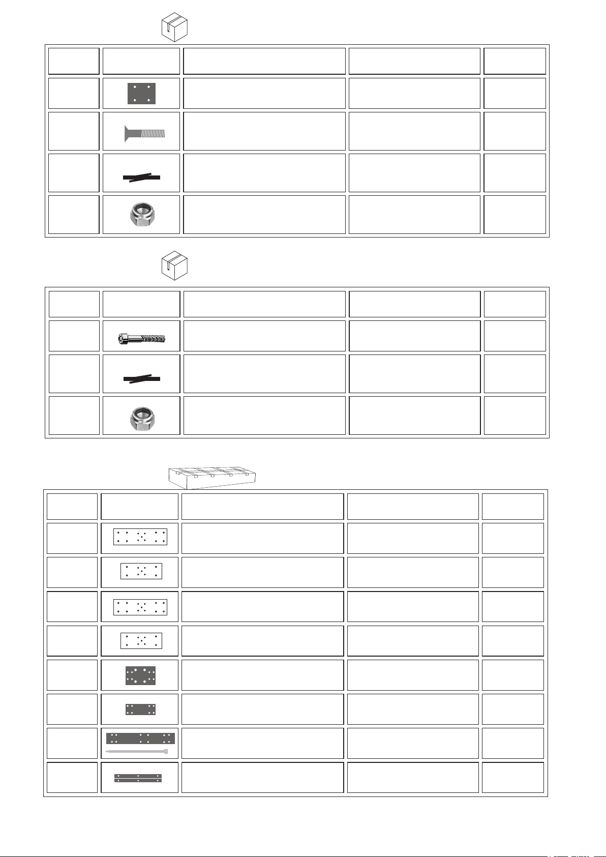
PART #
PART IMAGE
DESCRIPTION
SIZES
QUANTITY
PACKING LIST
PART #
PART IMAGE
DESCRIPTION
SIZES
QUANTITY
KARTON #1
A-0163
23035.50
S127-98
S934-98
S7991-9630
P0100026
P0100025
U-BOLT
SADDLE CLAMP
DIN 127 WASHER
DIN 934 NUT
Flat Head DIN 7991 Screw
Hose Clamp
Hose Clamp
M8 x 50mm
50mm
M8
M8
M6x30mm
25-40mm
20-32mm
BAG #1
2
2
4
4
6
4
4
P0100023
P0100024
P0100033
KARTON #1
S912-9660
S912-9650
S985-906
Hose Clamp
Hose Clamp
Hose Clamp
Allen DIN 912 Screw
Allen DIN 912 Screw
DIN 985 NUT
16-27mm
12-22mm
10-16mm
M6x60mm
M6x50mm
M6
8
12
12
BAG #2
12
24
36
S7991-9470
S125-94
S9021-94
S934-94
Flat Head DIN 7991 Screw
Washer DIN 125
Washer DIN 9021
DIN 934 NUT
M4x70mm
M4
M4
M4
6
6
12
18

PART #
PART IMAGE
DESCRIPTION
SIZES
QUANTITY
PART #
PART IMAGE
DESCRIPTION
SIZES
QUANTITY
KARTON #1
S7380-9660
Allen DIN 7380 Screw
M6x60mm
BAG #3
8
S9021-96
S985-906
KARTON #1
EAHYP035
EAHYP025
EAHYP020
DIN 9021
DIN 985 NUT
Plastic Blocks
Plastic Blocks
Plastic Blocks
M6
M6
35mm Ø
25mm Ø
20mm Ø
8
8
BAG #4
6
6
6
PART #
PART IMAGE
DESCRIPTION
SIZES
QUANTITY
PART #
PART IMAGE
DESCRIPTION
SIZES
QUANTITY
PART #
PART IMAGE
DESCRIPTION
SIZES
QUANTITY
KARTON #1
BAG #5
EA010085
S7991-9670
S127-96
S985-906
KARTON #1
S912-9680
S127-96
BOOM clamp 50mm
Flat Head DIN 7991 Screw
Lock washer DIN 127
DIN 985 NUT
Allen DIN 912 Screw
Lock washer DIN 127
70 x 50 x 6mm
70x6mm
M6
M6
80x6mm
M6
6
24
24
24
BAG #6
8
8
S985-906
KARTON #2
EA010261
EA010267
EA010252
EA010255
EA010320
DIN 985 NUT
14 MHz. Elements plates DRIVEN
14 MHz. Elements plates REFLECTOR
21/24/28 MHz. Elements plates DRIVEN
21/28 MHz. Elements plates REFLECTOR/D1
Boom to Mast Plate
M6
SPARE PARTS
250 x 70 x 5mm
200 x 70 x 5mm
250 x 60 x 5mm
200 x 60 x 5mm
150 x 150 x 10mm
8
1
1
2
2
1
EA010321
EA010323
EA010313
Boom to mast plate rear
Driven element Spacer plates
FEED LINE SQUARE TUBE SET
150 x 70 x 8mm
410 x 50 x 3mm
410 x 15 x 15mm
1
2
1

PART #
PART IMAGE
DESCRIPTION
SIZES
QUANTITY
KARTON #2
SPARE PARTS
XR3
A-A
XR3
A-B
EA0120502
XR3 20#1
XR3 20#1A
XR3 20#2
XR3 20#3
XR3 20#4
XR3 20#5
...
.
.
.
BOOM A
BOOM B
BOOM JOINT
20m Centrall part
DE 20m Central part
20m 2nd PART
20m 3rd PART
20m 4th PART
20m 5th PART
1527,5mm x 50mm
1527,5mm x 50mm
400mm x 45mm
1996,0mm x 35mm Ø
1996,0mm x 35mm Ø
998,0mm x 30mm Ø
998,0mm x 25mm Ø
998,0mm x 20mm Ø
998,0mm x 16mm Ø
1
1
1
1
1
4
4
4
4
XR3 20#6R
XR3 20#6D
XR3 15#1
XR3 15#1A
XR3 15#2
XR3 15#3
XR3 10#1
XR3 10#1A
XR3 10#2
20m 5th REFLECTOR TIPS
20m 5th DRIVEN TIPS
15m Centrall part
.
.
.
.
DE 15m Central part
15m 2nd PART
15m 3rd PART
10m Centrall part
DE 10m Central part
10m 3rd PART
1560,0mm x 13mm Ø
1060,0mm x 13mm Ø
1996,0mm x 25mm Ø
1996,0mm x 25mm Ø
998,0mm x 20mm Ø
998,0mm x 16mm Ø
1996,0mm x 20mm Ø
1996,0mm x 20mm Ø
998,0mm x 16mm Ø
2
2
1
1
4
4
1
1
4
XR3 15#4R
XR3 15#4D
XR3 10#3R
XR3 10#3D
15m REFLECTOR Final part
15m DRIVEN Final part
10m REFLECTOR Final part
10m DRIVEN Final part
1181,0mm x 13mm Ø
1014,0mm x 13mm Ø
1006,0mm x 13mm Ø
809,0mm x 13mm Ø
2
2
2
2
 Loading...