

Page 1

Manuale d’installazione
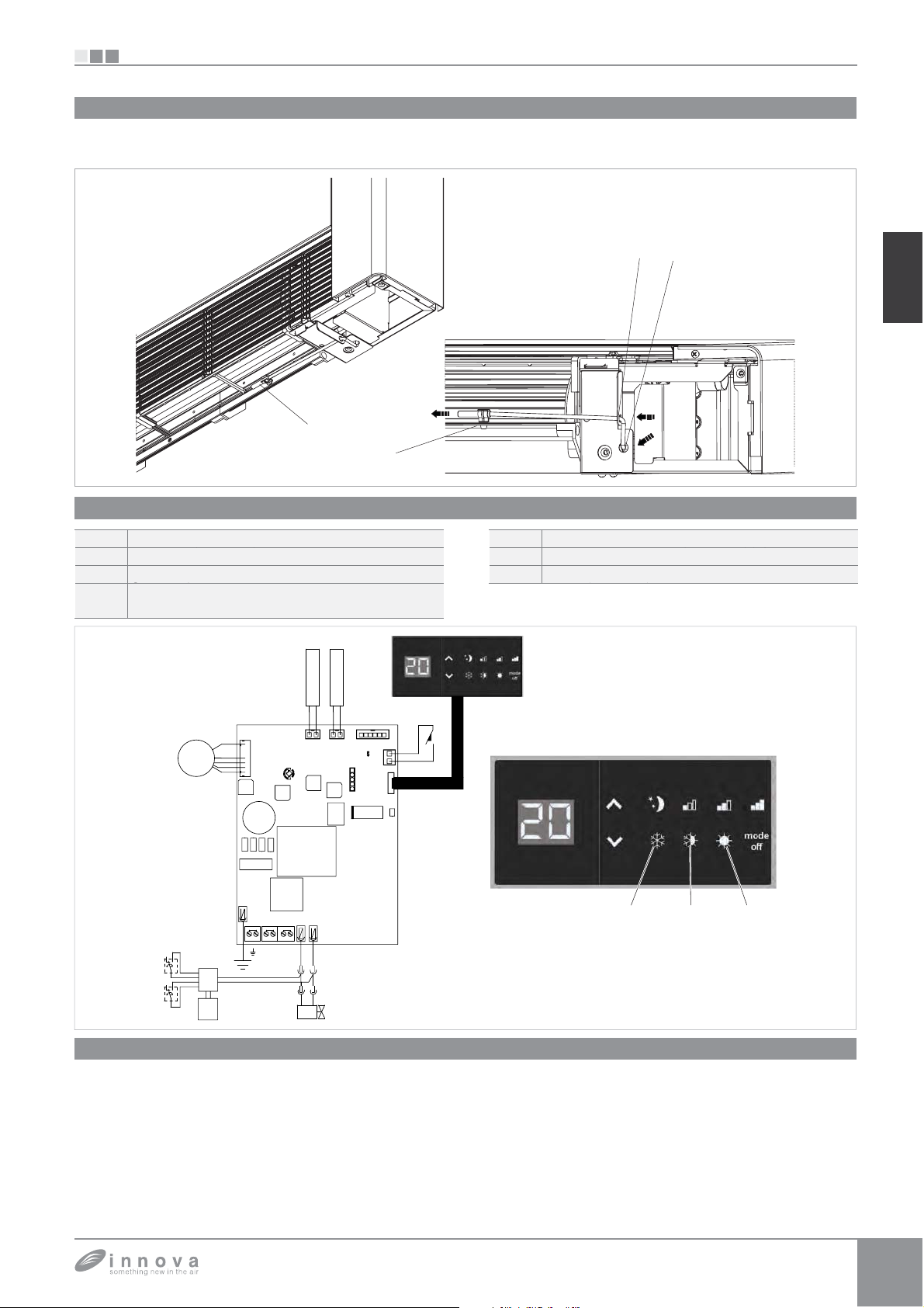
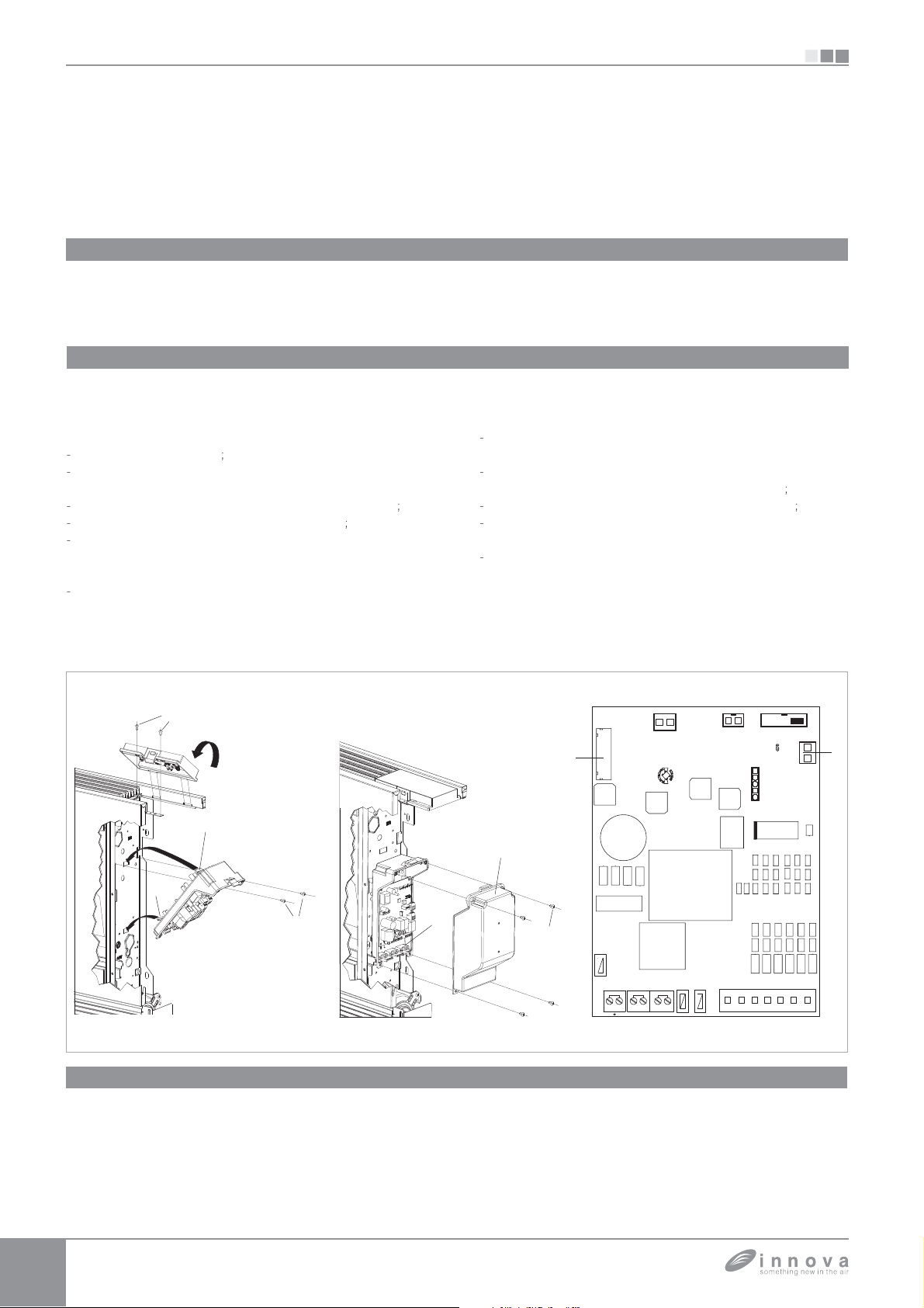
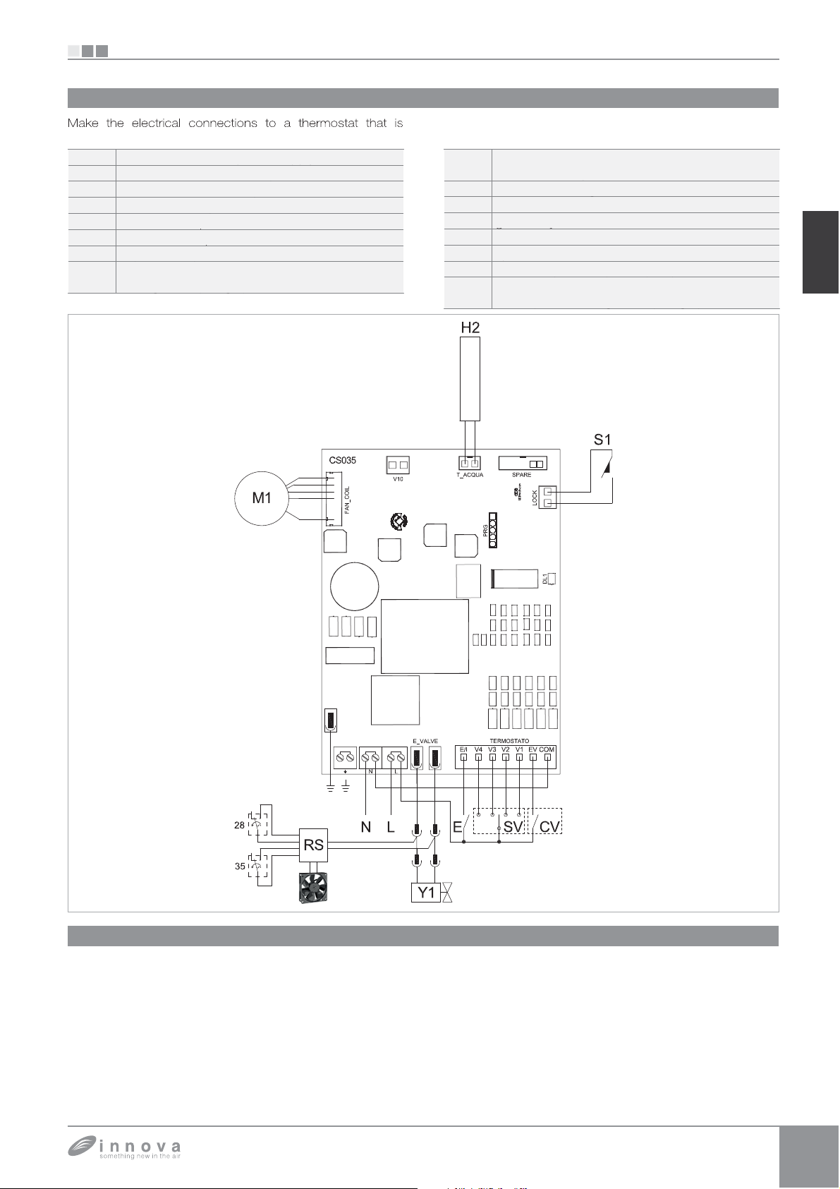
IT
Installation manual
EN
EB0644 - ER0645 - EM0649 - EB0647 - ER0648
EB0643
BB0642 - BM1151- BM0152
Page 2

Desideriamo innanzitutto ringraziarVi di avere deciso di accordare la vostra preferenza ad un
apparecchio di nostra produzione.
Come potrete renderVi conto avete effettuato una scelta vincente in quanto avete acquistato un
prodotto che rappresenta lo stato dell’Arte nella tecnologia della climatizzazione domestica.
Mettendo in atto i suggerimenti che sono contenuti in questo manuale, grazie al prodotto che avete
acquistato, potrete fruire senza problemi di condizioni ambientali ottimali con il minor investimento in
termini energetici.
Simbologia
I pittogrammi riportati nel seguente capitolo consentono
di fornire rapidamente ed in modo univoco informazioni
Pittogrammi redazionali
Utente
U
- Contrassegna le pagine nelle quali sono contenute
istruzioni o informazioni destinate all'utente.
Installatore
I
- Contrassegna le pagine nelle quali sono contenute
istruzioni o informazioni destinate all'installatore.
Pittogrammi relativi alla sicurezza
Avvertenza
- Che l’operazione descritta presenta, se non effettuata
nel rispetto delle normative di sicurezza, il rischio di
subire danni fisici.
Tensione elettrica pericolosa
- Segnala al personale interessato che l’operazione
descritta presenta, se non effettuata nel rispetto delle
normative di sicurezza, il rischio di subire uno shock
elettrico.
necessarie alla corretta utilizzazione della macchina in
condizioni di sicurezza.
Service
S
- Contrassegna le pagine nelle quali sono contenute
istruzioni o informazioni destinate all'installatore
SERVIZIO ASSISTENZA TECNICA CLIENTI.
Pericolo di forte calore
- Delle normative di sicurezza, il rischio di subire
bruciature per contatto con componenti con elevata
temperatura.
Divieto
- Contrassegna azioni che non si devono assolutamente
fare.
Page 3

1
1.1 4
Avvertenze generali..............................................................
Generale
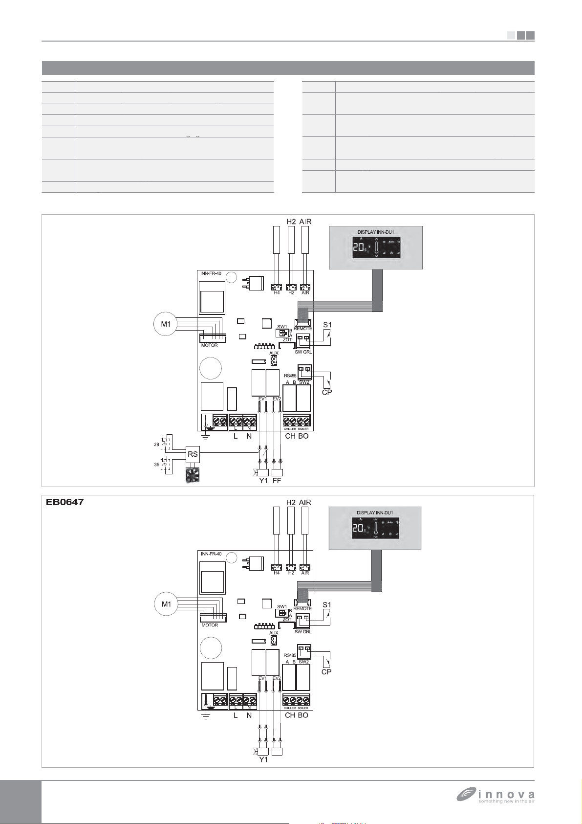
2 EB0644 - ER0645 - EB0647 - ER0648
2.1 5
2.2 5
2.3 6
2.4 6
2.5 7
2.6 7
2.7 8
2.8 9
Montaggio, settaggio e connessioni pannelli di comando a bordo macchina EB0644, ER0645, EB0647, ER0648. . .
Montaggio ....................................................................
Settaggio funzioni ausiliarie dip-switch A e B ...........................................
Connessione ingresso contatto presenza CP...........................................
Montaggio sonda temperatura aria (solo per modelli EB0644 e EB0647).......................
Impostazione sistema di regolazione raffrescamento/riscaldamento automatico..................
Connessioni EB0644 e EB0647 ....................................................
Connessioni ER0645 e ER0648 ....................................................
3 EM0649
3.1 10
3.2 11
3.3 11
Montaggio e connessioni pannello di controllo remoto a muro EM0649 .......................
Connessioni EM0649 ............................................................
Connessione ingresso contatto presenza CP...........................................
4 EB0643
4.1 12
4.2 12
4.3 13
4.4 13
4.5 13
Montaggio e connessioni pannello di comando a bordo macchina EB0643 ....................
Montaggio ....................................................................
Montaggio sonda temperatura aria ..................................................
Connessioni EB0643 ............................................................
Gestione sonda acqua kit EB0643 ..................................................
IT
5 BB0642
5.1 14
5.2 14
5.3 14
5.4 15
5.5 15
5.6 16
5.7 16
5.8 17
Montaggio e connessioni controllo ventilatore per regolazione remota BB0642 ..................
Montaggio ....................................................................
Segnalazioni del LED ............................................................
Schema connessioni BB0642 con termostati 3 velocità ...................................
Collegamenti BB0642 con termostati a 3 velocità .......................................
Gestione sonda acqua BB0642 con termostato 3 velocità .................................
Schema connessioni BB0642 con termostati 0-10V .....................................
Collegamenti BB0642 con termostati 0-10V ...........................................
6 BB0642 + BM1151
6.1 18
Schema connessioni BB0642 + BM1151 .............................................
7 BB0642 + BM1152
7.1 19
8
8.1 20
8.2 20
8.3 20
Schema connessioni BB0642 + BM1152 .............................................
Versioni Full flat, RS e con attacchi a destra
Collegamenti versioni full flat .......................................................
Collegamenti versioni RS .........................................................
Collegamento motore nelle versioni con attacchi idraulici a destra............................
Page 4
GENERALE
1.1
Avvertenze generali
Questa istruzione è parte integrante del libretto
dell'apparecchio sul quale viene installato il kit. A tale
libretto si rimanda per le avvertenze generali e per le
regole fondamentali di sicurezza.
Il presente manuale è destinato esclusivamente al
tecnico installatore qualificato ed autorizzato, che dovrà
essere adeguatamente istruito ed in possesso di tutti i
requisiti psicofisici richiesti a norma di legge.
Tutte le operazioni dovranno essere eseguite con cura
e a regola d’arte, in conformità delle norme di sicurezza
sul lavoro vigenti.
Dopo aver tolto l’imballo assicurarsi dell'integrità e della
completezza del contenuto. In caso di non rispondenza
rivolgersi all'Agenzia che ha venduto l'apparecchio.
SIU
GENERALE
È vietato modificare i dispositivi di sicurezza o di
regolazione senza l’autorizzazione e le indicazioni del
costruttore dell’apparecchio.
È vietato disperdere e lasciare alla portata di bambini il
materiale dell'imballo in quanto può essere potenziale
fonte di pericolo.
Gli interventi di riparazione o manutenzione devono
essere eseguiti dal Servizio Tecnico di Assistenza
o da personale qualificato secondo quanto previsto
dal presente libretto. Non modificare o manomettere
l’apparecchio in quanto si possono creare situazioni
di pericolo ed il costruttore dell’apparecchio non sarà
responsabile di eventuali danni provocati.
Page 5
SI
U
D
E
C
F
I
g
.
p
p
(
);
(
f
(
);
);
fissare
e
);
(MOTOR )
;
f
inali p
;
(
)
;
lla l
ll'i
i
)
f
lla b
.
ssare
aus
e
G);
(
);
pp
;
;
;
acc
destra fare
fo
EB0644 - ER0645 - EB0647 - ER0648
EB0644 - ER0645 - EB0647 - ER0648
Montaggio, settaggio e connessioni pannelli di comando a bordo macchina
EB0644, ER0645, EB0647, ER0648
2.1
IT
I comandi dispongono di due contatti puliti indipendenti per il
comando di un refrigeratore e di una caldaia e di un ingresso
presenza. Le versioni a 2 tubi dispon
ono di una uscita a
230V per il pilotaggio dell'elettrovalvola estiva ed invernale
2.2
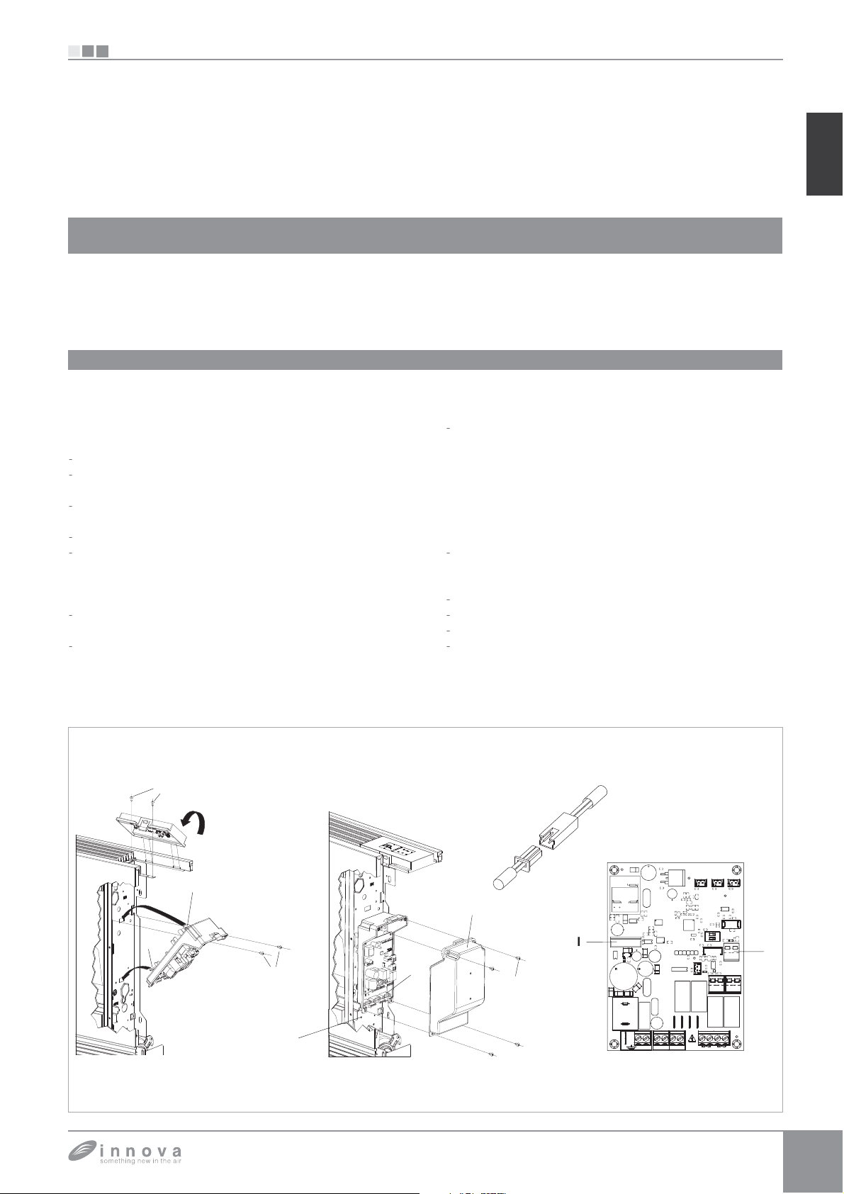
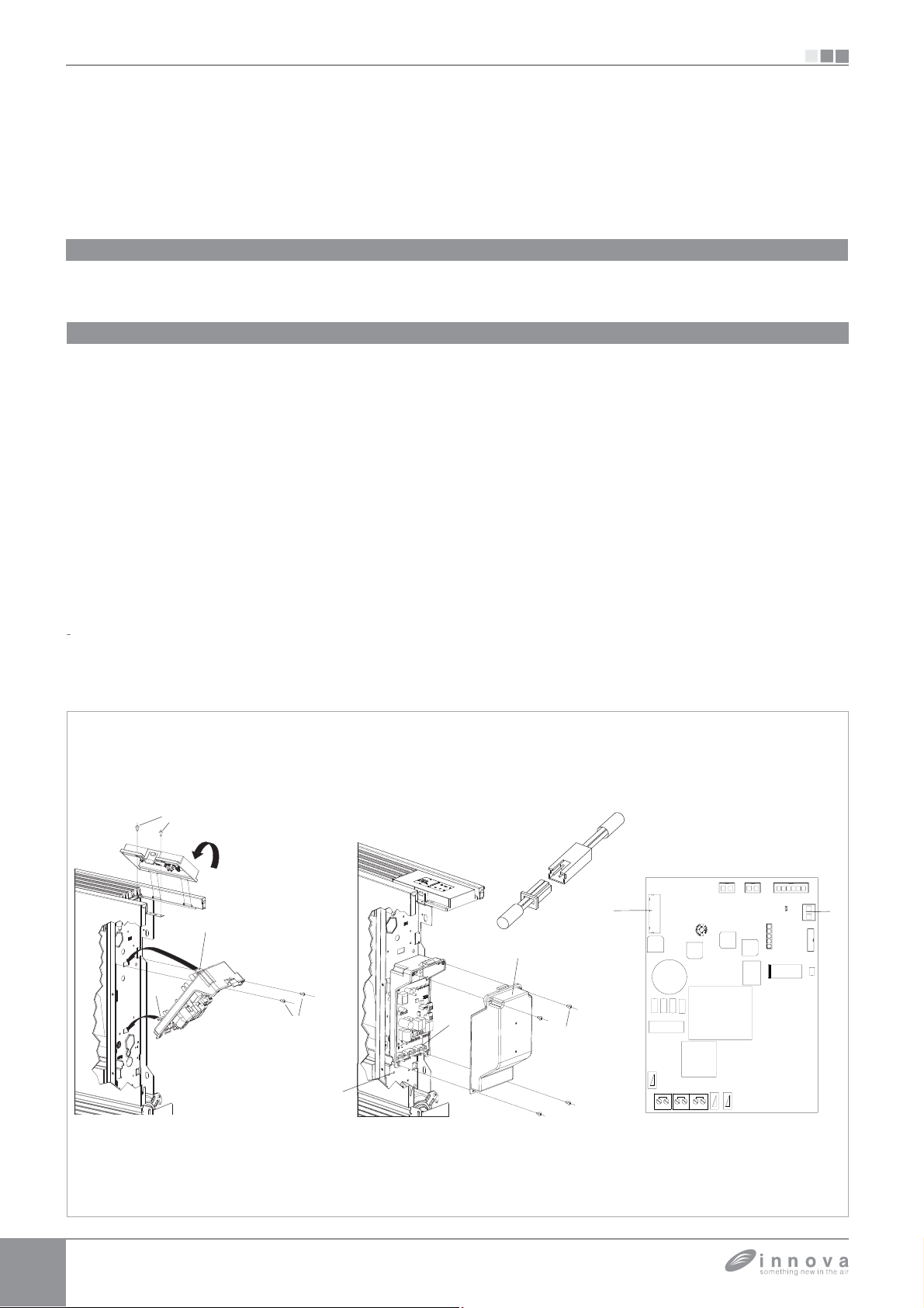
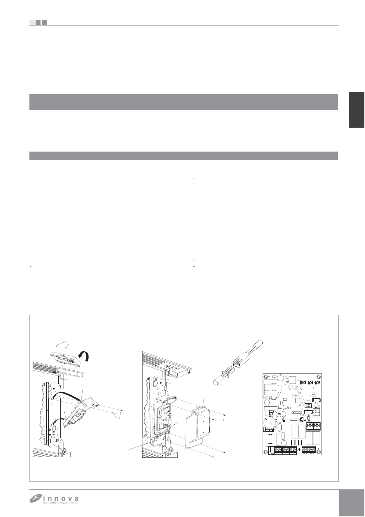
Montaggio
Infilare il pannello di controllo nella sua sede nella
su
eriore dell'apparecchio e fissarlo con le due viti a
corredo
rif. A).
Per installare la scatola dei collegamenti:
aprire la scatola (rif. B
incastrare il dente inferiore nell'apposita feritoia
rif. C) sul
ianco dell'apparecchio;
agganciare la parte superiore della scatola al fianco
D
fissarla con le due viti a corredo (rif. E
il cavo di terra alla struttura del ventilconvettor
rif. M) utilizzando la vite a corredo (la forza minima che
eve essere esercitata per l'avvitamento deve essere di
circa 2N
collegare il connettore rapido del motore
uello presente sulla scheda (rif. I) *
ei 2 terminali del morsetto SW GRL (rif. L) è presente
un ponte che garantisce il
unzionamento delle versioni
LI e RSI prive di microinterruttore.
er le altre versioni togliere il ponte e collegare i due
arte
rif.
a
mentre le versioni a 4 tubi dispongono di due uscite
indipendenti a 230V per il pilotaggio di una elettrovalvola
estiva ed una invernale
term
rovenienti dal microinterruttore sicurezza
griglia. *
collegare il connettore della sonda acqua
resente sull'apparecchio
a sonda temperatura acqua contro
a
nterno delle batterie e determina l'avviamento
a temperatura
el ventilatore in base a dei parametri preimpostat
funzioni di minima invernale e di massima estiva
Veri
icare che sia correttamente inserita nel pozzetto
presente su
atteria
eseguire i collegamenti elettrici, ordinare i cablaggi,
fi
i cavi con l'
ilio dei 3 cavallotti in dotazion
rif.
chiudere la scatola fissando le 4 viti
imontare il fianchetto estetico dell'a
rif. H
arecchio
vvitare la vite superiore sul pannello di controllo
posizionare il copri vite nell'apposito alloggiamento sul
annello di controllo
Per versioni con att
hi idraulici a
riferimento al relativo paragra
rif. F
.
SEC
NC
NC
PRI
AUX
+
MOTOR
-+
+
H
4
+
23
1
12 2112
LN
AIRH2H4
SW1
1
REMOTE
ON
B
A
ZOT
RSKD
41
AUX
SW GRL
211221
RS485
BA
SW2
EV2NEV1N
4321
BOILERCHILLER
Page 6
EB0644 - ER0645 - EB0647 - ER0648
A
A
f
pp
à.
T
:
ì
O
O
,
à
ù
O
A
g
g
.
2.3
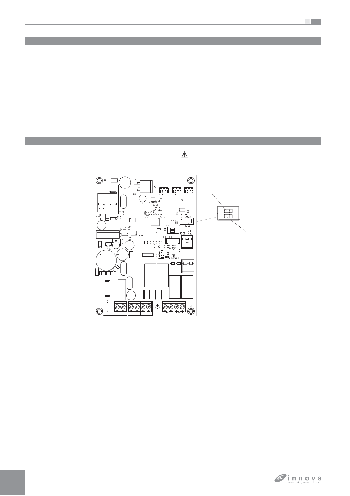
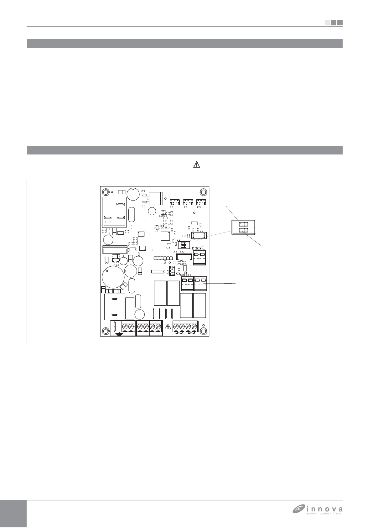
Settaggio funzioni ausiliarie dip-switch A e B
SI
ulla scheda elettronica del comando sono posizionati
due dip-switch per la con
dell'a
arecchio in funzione delle necessit
igurazione del funzionamento
ramite il cursore A si modifica la logica del
funzionamento notturno in riscaldamento
ella posizione ON viene inibita la ventilazione
permettendo cos
alla macchina di riscaldare gli
ambienti mediante irraggiamento e convezione
naturale, come avviene nei radiatori tradizionali; in
Connessione ingresso contatto presenza CP
2.4
lla chiusura del contatto colle
C) tutte le utenze ven
ono spente
ato all'ingresso SW2 (rif.
SEC
SEC
NC
NC
NC
NC
PRI
PRI
AUX
AUX
+
+
MOTOR
MOTOR
+
+
RSKD
RSKD
-+
-+
AUX
AUX
SW1
SW1
1
1
ZOT
ZOT
posizione
FF si ha invece il normale funzionamento
el ventilatore.
osizionando il cursore B in
in raffrescamento
velocit
anche dopo il raggiungimento del set point
per consentire un pi
la ventilazione continua alla minima
regolare funzionamento della
sonda di temperatura. Il passaggio alla condizione di
riscaldamento annulla la condizione; con il cursore
nella posizione
FF si disabilita tale funzione.
on è possibile collegare l’ingresso in parallelo a quello
di altre schede elettroniche (usare contatti separati).
AIRH2H4
AIRH2H4
SW1
SW1
1
1
ON
ON
B
B
REMOTE
REMOTE
ON
ON
B
B
A
A
41
41
SW GRL
SW GRL
N viene abilitata, solo
4
4
23
23
1
1
12 2112
12 2112
+
+
LN
LN
211221
211221
RS485
RS485
BA
BA
SW2
SW2
EV2NEV1N
EV2NEV1N
4321
4321
BOILERCHILLER
BOILERCHILLER
Page 7
SI
p
(
C)
gg
.
g
affrescamento o de
scaldamento escludendo
g
g
t
p
p
g
f
a fu
p
p
e.
2.5
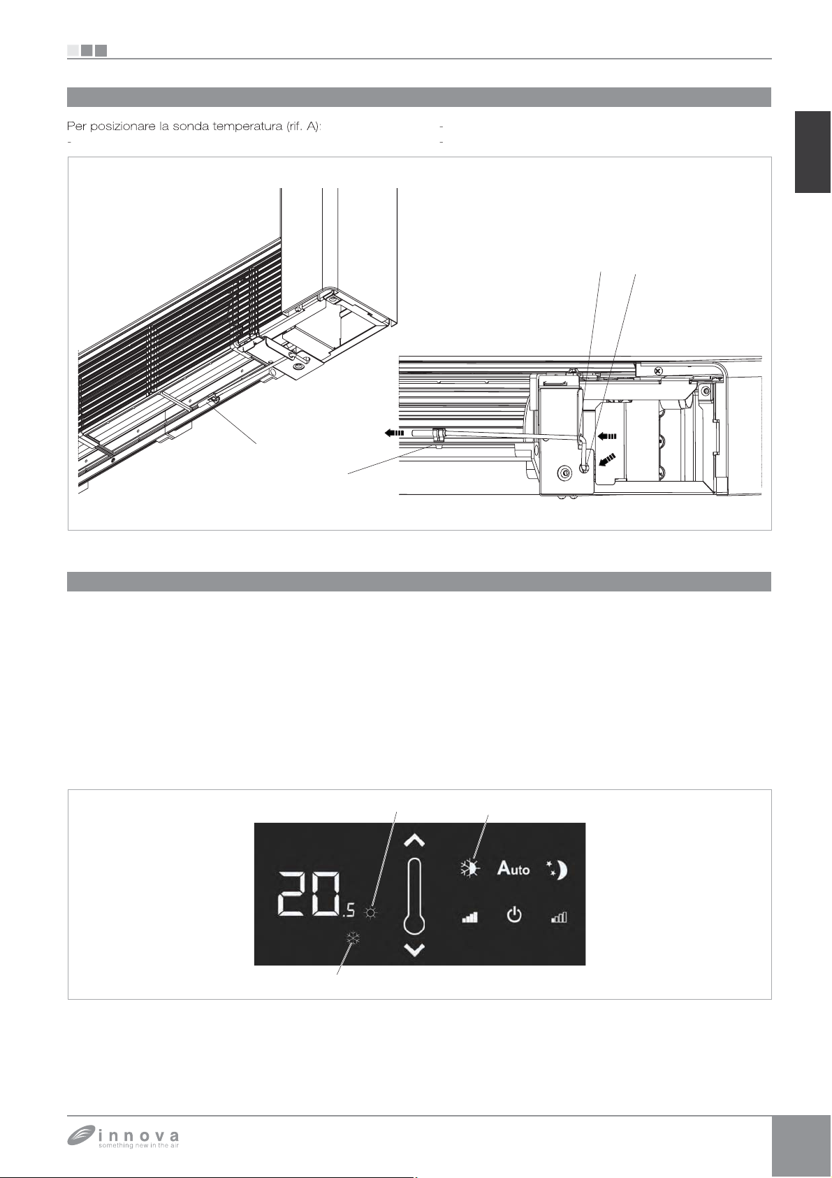
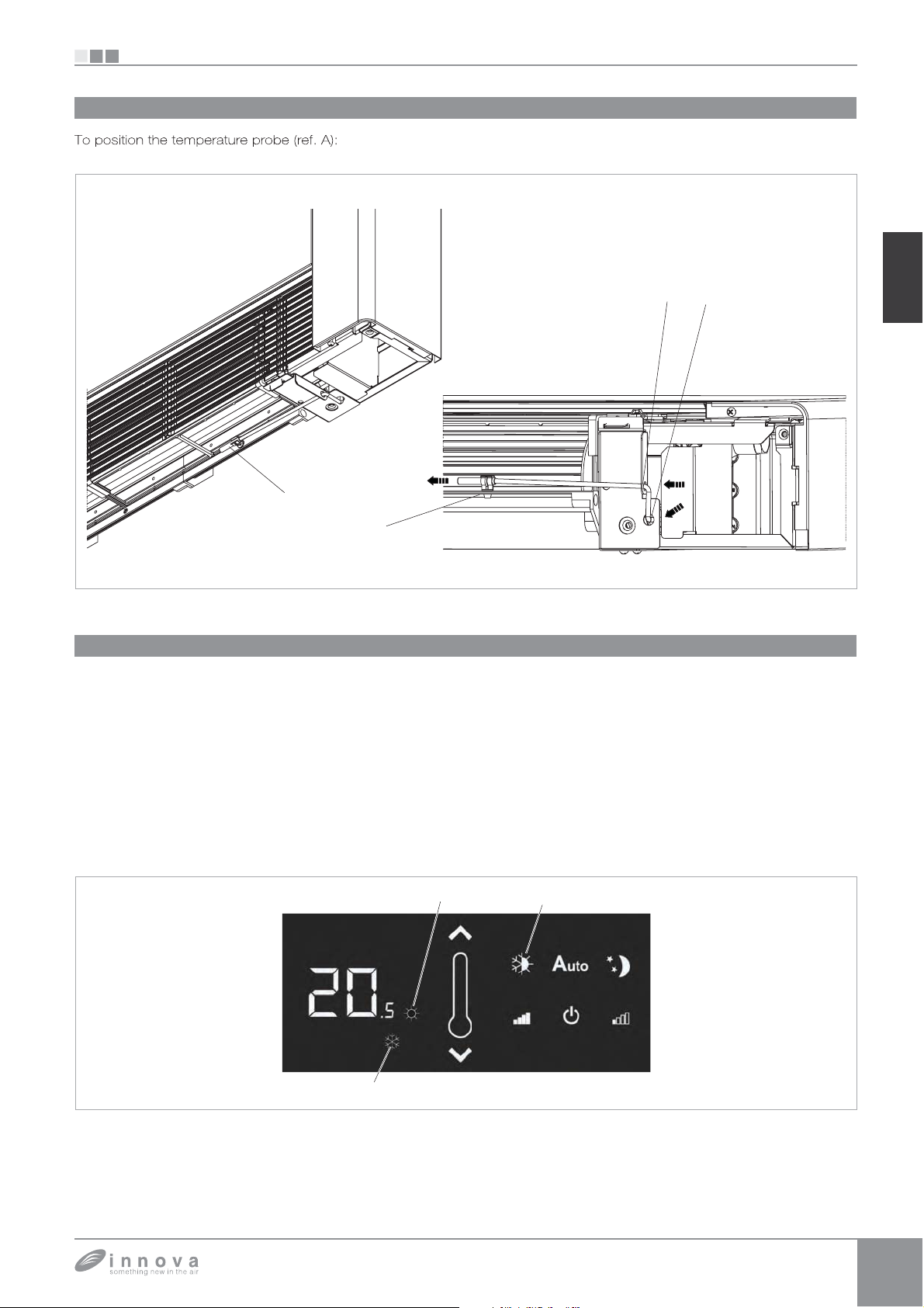
Montaggio sonda temperatura aria (solo per modelli EB0644 e EB0647)
EB0644 - ER0645 - EB0647 - ER0648
far passare la sonda nel foro della s
alla (rif. B)
infilare la sonda nel foro inferiore
fissare la sonda all'apposito a
rif.
ancio (rif. D)
IT
Impostazione sistema di regolazione raffrescamento/riscaldamento automatico
2.6
L’impostazione di questo tipo di re
l comando di effettuare automaticamente la selezione
l r
la normale selezione manuale. Tale re
particolarmente indicata per le versioni a 4 tubi. Questo
sistema di re
ecnico installatore qualificato ed autorizzato. Per attivare
uesta funzione mantenere
er 10 secondi fino all’accensione simultanea dei simboli
affrescamento (rif. C) e riscaldamento (rif. B). Per ritornare
uovamente alla regolazione del funzionamento solo
affrescamento o solo riscaldamento manuale
olazione può essere attivato solo da un
l ri
remuto il tasto est/inv (rif. A)
olazione permette
olazione è
remere il
tasto est/inv (rif. A) per 10 secondi fino allo spe
ei simboli raffrescamento (rif. C) e riscaldamento (rif.
). Premere nuovamente il tasto per selezionare la
unzione inverno. Verificare il funzionamento del simbolo
iscaldamento (rif. B) (acceso con setpoint superiore
a temperatura ambiente, spenti entrambi con setpoint
inferiore). Premere 1 volta il tasto est/inv per selezionare
l
nzione estate. Verificare il funzionamento del simbolo
affrescamento (rif. C) (acceso con setpoint inferiore alla
tem
eratura ambiente, spenti entrambi con set
uperiore). Questa selezione viene mantenuta anche in
di interruzione d’alimentazion
nimento
oint
Page 8
EB0644 - ER0645 - EB0647 - ER0648
lda
pq
)
pq()
p
r
gg
)
)
)
)()
g
/
z
g
)
(p )
)
)
)
()
(
)
py)
S
gg
2.7
Connessioni EB0644 e EB0647
SI
I
M1
1
1
L-N
EB0644
onda temperatura acqua ca
onda temperatura acqua fredda (*
motore ventilatore DC inverte
elettrovalvola acqua calda (uscita in tensione a
230V/ 50Hz 1A
elettrovalvola acqua fredda (uscita in tensione a
230V/ 50Hz 1A) (*
collegamento alimentazione elettrica 230V
50H
H4
scita consenso caldaia (contatto pulito max 1A
H
P
scita consenso refrigeratore (contatto pulito
max 1A
scita per servomotori pannello aspirazione
mobile (uscita in tensione a 230V/ 50Hz 1A
ingresso sensore presenza
ventilconvettore viene posto in stand-by.
cablaggio versione R
resenti solo nel pannello EB0647 per versione
4 tubi.
se chiuso, il
H4
Y2
Page 9
SI
A-B
Y2
O
S
5
8
)
(p p )
a
pq
pq()
r
gg
)
)
)
)()
g
(p )
)
(p )
)
)sci
)
()
(
v
)
py)
S
gg
ubi
ò
f
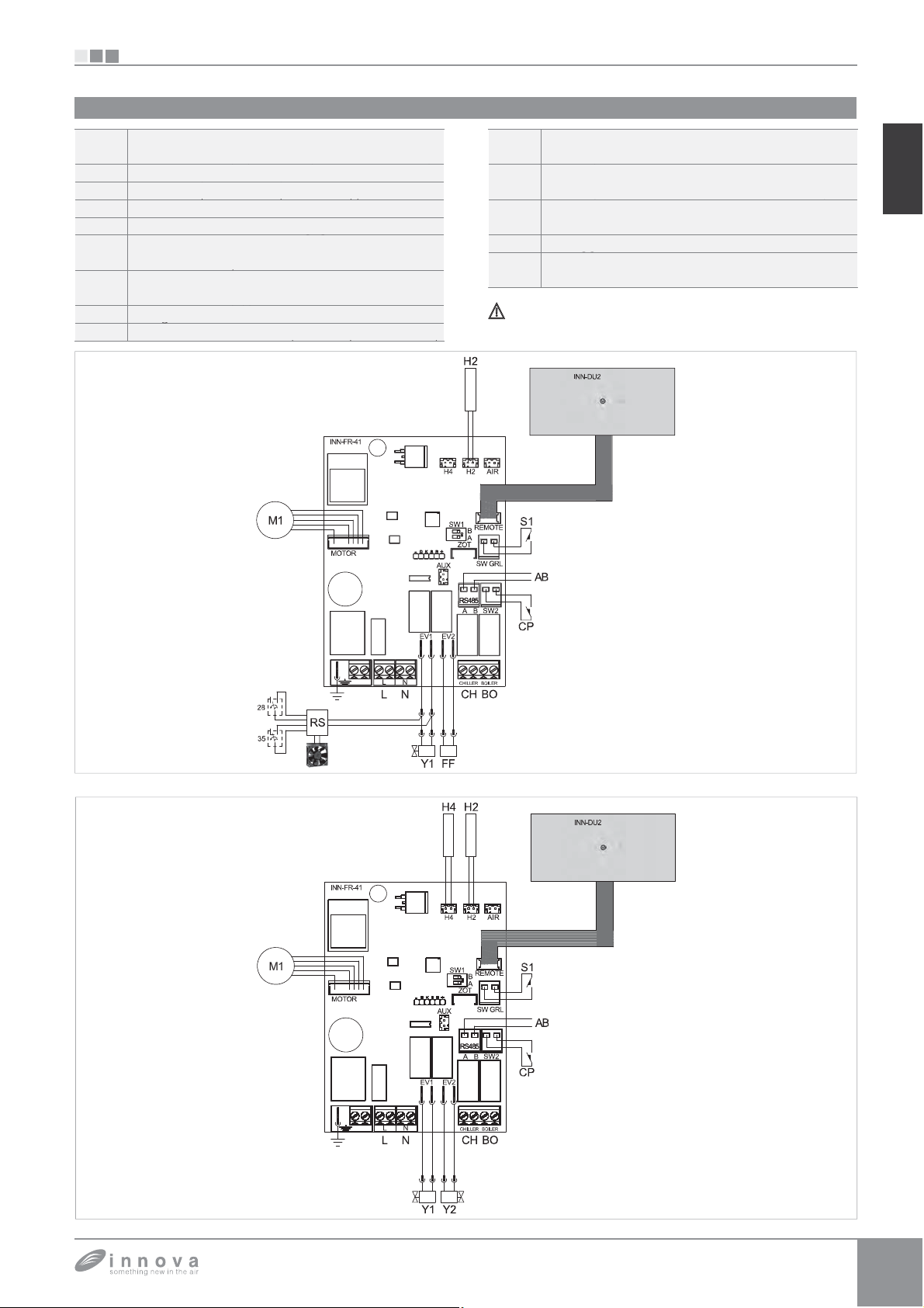
2.8
Connessioni ER0645 e ER0648
EB0644 - ER0645 - EB0647 - ER0648
4
M
LB
ER064
collegamento seriale per comando remoto a
muro EM0649 (rispettare la polarizzazione A-B
sonda temperatura acqua cald
motore ventilatore DC inverte
lettrovalvola acqua calda (uscita in tensione a
30V/ 50Hz 1A
lettrovalvola acqua fredda (uscita in tensione a
30V/ 50Hz 1A) (*
uscita consenso caldaia (contatto pulito max 1A
H
R
scita consenso refrigeratore (contatto pulito
ax 1A
ta per servomotori pannello aspirazione
obile (uscita in tensione a 230V/ 50Hz 1A
ingresso sensore presenza
entilconvettore viene posto in stand-by.
ablaggio versione R
resenti solo nel pannello ER0648 per versione
t
.
Il pannello di comando pu
di inter
accia INN-DU2.
IT
se chiuso, il
funzionare anche se privo
4
Page 10
EM0649
ù
/
(
v
)
.
à
f
(
);
(
(
(
f
f
(
A
/
VDC (
g
.
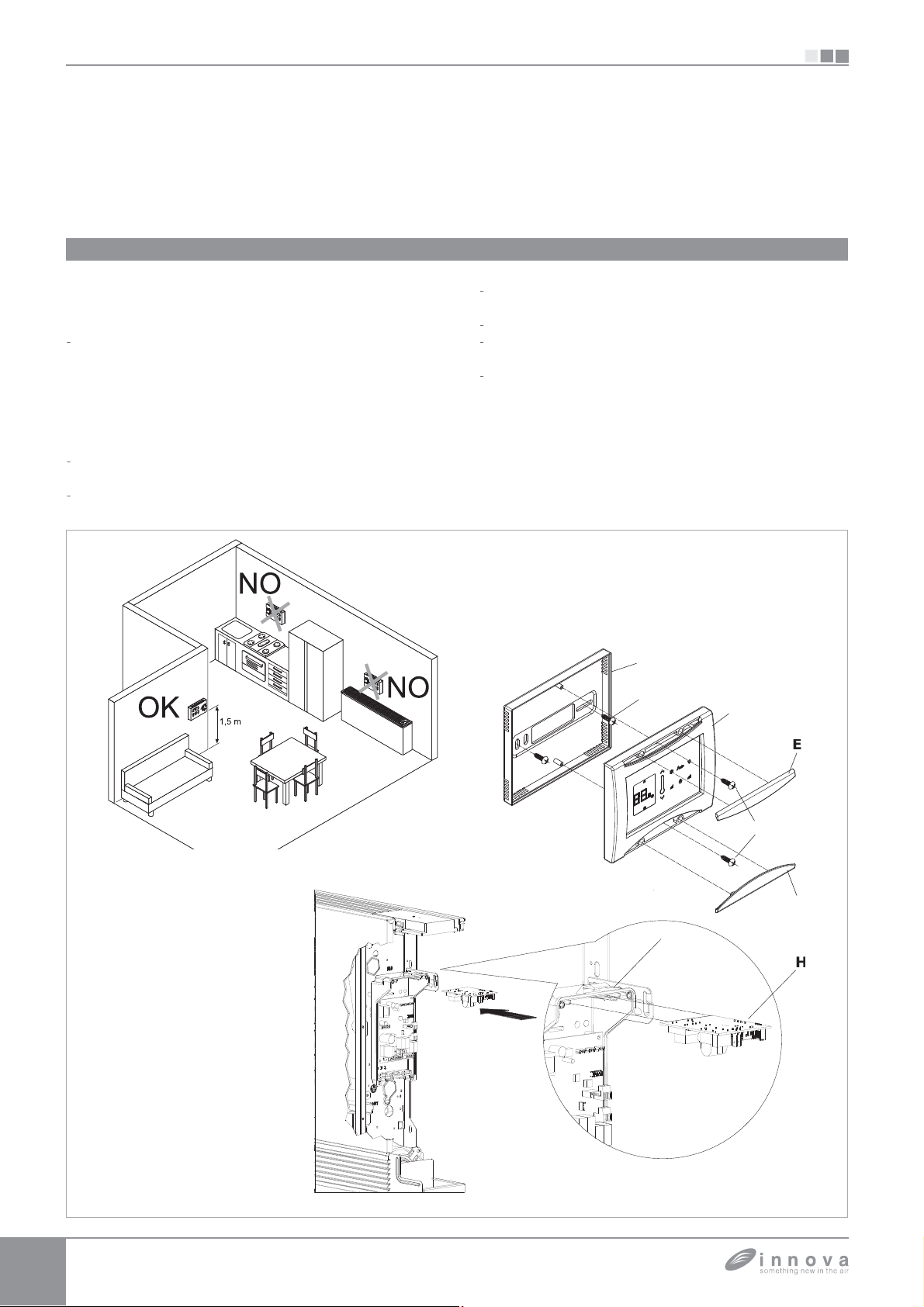
3.1
Montaggio e connessioni pannello di controllo remoto a muro EM0649
Il controllo remoto a muro EM0649 è un termostato elettronico
dotato di sonda di temperatura) con possibilità di controllo
su uno o pi
comando elettronico per remotizzazione ER0645 o ER0648.
Installare il controllo remoto a muro EM0649 lontano
da porte e
nterne e ad un’altezza di circa 1,5 m dal pavimento
Il controllo remoto a muro è presente all’interno della
confezione gi
istruzioni per il
aprire i coperchi facendo leva sui due dentini sporgenti
con un cacciavite
svitare le due viti di fissaggio della scheda elettronica
apparecchi (fino ad un massimo di 30) dotati di
o finestre e da fonti di calore
entilconvettori, fornelli, raggi diretti del sole
assemblato, pertanto seguire le seguenti
issaggio:
E e F
caloriferi,
, su pareti
EM0649
alla base del controllo
utilizzare la base del controllo
muro i punti di fissaggio
orare la parete;
passare i cavi elettrici attraverso le
sulla base;
fissare la base del controllo alla parete utilizzando viti e
tasselli adeguati
corredo viene fornita una scheda alimentatore da 230
rif. H ) per l’alimentazione elettrica del controllo che va
installata nella scatola dei colle
bordo di uno degli apparecchi dotati di comando elettronico
er remotizzazione ER0645 o ER0648
rif. D);
rif. A) per tracciare a
utilizzare i due fori opposti);
inestre presenti
rif. B).
amenti (rif. G) presente a
SI
12
Page 11
SI
p
di
.
i;
g
(
bipol
m
/
i L ed N dell
INN-FR
.
A
/
(
)
p
.
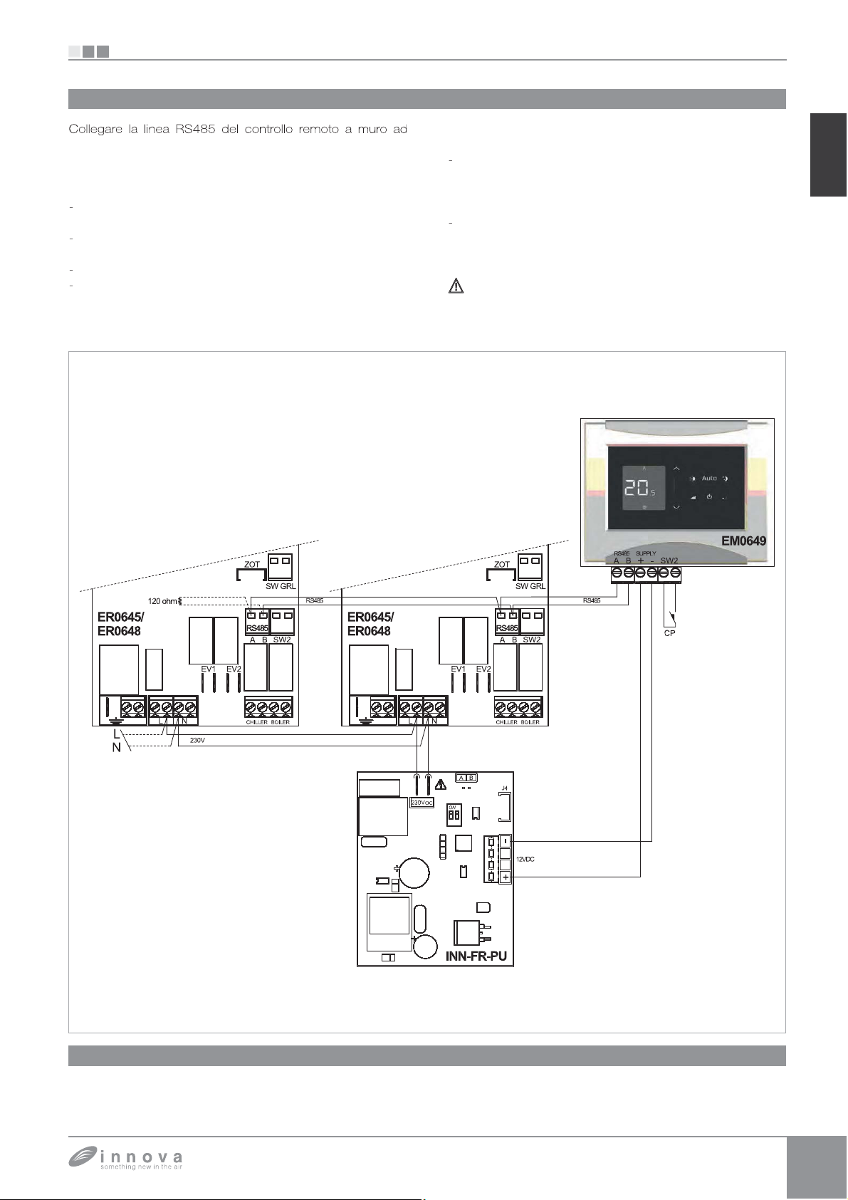
3.2
Connessioni EM0649
EM0649
no o più (fino ad un massimo di 30) apparecchi dotati di
comando elettronico
me
ante cavo bipolare adatto per connessione seriale
RS485 tenendolo separato dai cavi d'alimentazione elettrica
seguire un tracciato in modo da ridurre al minimo la
unghezza delle derivazion
terminare la linea con la resistenza da 120 ohm in
dotazione;
on effettuare collegamenti a “stella”;
il collegamento con il cavo RS485 è polarizzato,
rispettare le indicazioni “A” e “B” su o
collegata
per la connessione utilizzare preferibilmente
er remotizzazione ER0645 o ER0648
ni periferica
n cavo
0,35 m
ollegare i terminali di alimentazione 230V della
cheda alimentatore 230
morsett
0645 o ER0648
ollegare i terminali di alimentazione + e - SUPPLY
el controllo a muro EM0649 alla scheda alimentatore
30/12VDC rispettandone la polarità.
limentare il controllo remoto unicamente con la
cheda alimentatore da 230
are schermato con sezione minima di
;
12VDC INN-FR-B3 ai
a scheda
12 VDC in dotazione.
-41 del comando
IT
Connessione ingresso contatto presenza CP
3.3
L'ingresso SW2 va connesso ad un contatto pulito
tensione
e alla chiusura del contatto il pannello di controllo
non in
M0649 e tutti i comandi elettronici
R0645 o ER0648 collegati all'EM0649 vengono spenti
er remotizzazione
Page 12
EB0643
(
).
;
;
(
);
(
);
q
;
OCK (
p
;
lla l
ll'i
lla b
ggi
(
pp
gg
acc
destra fare
g
ON/
g
4.1
Montaggio e connessioni pannello di comando a bordo macchina EB0643
Il comando a bordo macchina con selettore di velocità e
OFF a pulsante, termostato ambiente re
olabile da 5 a 40°C,
selettore estate inverno e funzione di minima temperatura
Montaggio
4.2
Infilare il pannello di controllo nella sua sede nella parte
uperiore dell'apparecchio e fissarlo con le due viti a
corredo
rif. A
er installare la scatola dei collegamenti:
- aprire la scatola (rif. B);
incastrare il dente inferiore nell'apposita feritoia (rif. C)
ul fianco dell'apparecchio
agganciare la parte superiore della scatola al fianco
(rif. D)
fissarla con le due viti a corredo
rif. E
fissare il cavo di terra (rif. M) alla struttura
dell'apparecchio utilizzando la vite a corredo
minima che deve essere esercitata per l'avvitamento
deve essere di circa 2N
collegare il connettore rapido del motore (FAN_COIL )
a
uello presente sulla scheda (rif. I) *
ei 2 terminali del morsetto L
rif. L) è presente un
ponte che garantisce il funzionamento delle versioni
LI e RSI prive di microinterruttore.
Per le altre versioni togliere il ponte e collegare i due
terminali
rovenienti dal microinterruttore sicurezza
EB0643
la forza
invernale (30°C) e massima temperatura estiva (20°C) è
adatto per l'installazione a bordo macchina e dispone di una
scita a 230 V per il controllo di un'elettrovalvola.
riglia. *
collegare il connettore della sonda acqua (rif. F)
resente sull'apparecchio;
a sonda temperatura acqua contro
a
nterno delle batterie e determina l'avviamento
el ventilatore in base a dei parametri preimpostati
(funzioni di minima invernale e di massima estiva).
Verificare che sia correttamente inserita nel pozzetto
presente su
atteria.
seguire i collegamenti elettrici, ordinare i cabla
fissare i cavi con l'ausilio dei 3 cavallotti in dotazione
rif. G);
chiudere la scatola fissando le 4 viti
- rimontare il fianchetto estetico dell'a
avvitare la vite superiore sul pannello di controllo;
- posizionare il copri vite nell'apposito allo
annello di controllo;
r versioni con att
riferimento al relativo para
hi idraulici a
rafo.
SI
a temperatura
,
rif. H);
arecchio;
iamento sul
CS 35
FAN_COIL
T_ARIA
E_VALVE
T_ACQUA SPARE
PRG
GDBtech.com
LOCK
DISPLAY
DL1
Page 13

SI
A
3
(
):
(
)
(
C)
(
pq
igli
gg
)
)
z
g
S
gg
ia
p
p
q
p
p
S
g
,
p
p
success
.
g
g
.
p
(sop
(
).
4.3
Montaggio sonda temperatura aria
EB0643
Per posizionare la sonda temperatura
far passare la sonda nel foro della spalla
Connessioni EB0643
4.4
H
M
sonda temperatura acqua
otore ventilatore DC inverter
crointerruttore sicurezza gr
1
lettrovalvola acqua (uscita in tensione a 230V/
50Hz 1A
rif. A
a
rif. B
infilare la sonda nel foro inferiore
fissare la sonda all'apposito aggancio
collegamento alimentazione elettrica 230V/50H
-N
cablaggio versione R
IR
onda temperatura ar
rif.
rif. D).
IT
EB064
4.5
CS 35
M1
28
RS
35
FAN_COIL
Gestione sonda acqua kit EB0643
H2AIR
T_ACQUA SPARE
T_ARIA
GDBtech.com
LOCK
PRG
DISPLAY
DL1
E_VALVE
LN
1
Se la scheda rileva la sonda di rilevazione della tem
dell’ac
ua,
resente sull’apparecchio
osizionata
ell’apposito pozzetto della batteria, l’avvio avviene in
condizioni normali.
l’assenza viene se
del led rosso e blu
Per confermare il funzionamento
e la sonda non viene connessa
nalata con il lampeggio contemporaneo
e il blocco del funzionamento.
rivo di sonda, andrà
remuto il pulsante estate/inverno per 5 secondi (rif A).
Questa condizione verrà memorizzata dalla scheda
S1
eratura
er tutti
DISPLA CS 4
i
ivi avvii
n ogni caso nel momento in cui la sonda viene colle
ipristina il normale funzionamento con so
lie di temperatura
e la macchina lavora con la sonda connessa e la
tem
eratura dell’acqua non è idonea al funzionamento
attivo
ra i 20°C in raffreddamento, sotto i 30°C in
iscaldamento) la ventilazione sarà arrestata e l’anomalia
arà segnalata dal lampeggio del corrispondente LED della
funzione selezionata
blu raffresc.C o rosso riscald.D
ata si
Page 14
BB0642
à
t
.
ò
p
p
.
i:
;
f
;
);
);
pp
p
);
g
p
inali
igli
ll
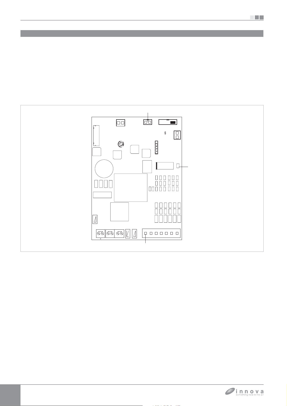
ggi
f
)
)
pp
gg
acc
destra fare
g
g
g
.
p
g
.
g
p
p
gg
g
5.1
SI
BB0642
Montaggio e connessioni controllo ventilatore per regolazione remota BB0642
Montato a bordo macchina consente di gestire il motore,
con velocit
fisse; può essere abbinato ai comandi con
ermostato e a tutti i comandi presenti in commercio
In alternativa la regolazione del motore pu
5.2
Montaggio
Infilare il
annello cieco nella sua sede nella
essere effettuata
arte superiore
ell'apparecchio e fissarlo con le due viti a corredo (rif. A)
er installare la scatola dei collegament
aprire la scatola (rif. B)
incastrare il dente inferiore nell'apposita feritoia (rif. C) sul
ianco dell'apparecchio
agganciare la parte superiore della scatola al fianco (rif.
D
fissarla con le due viti a corredo (rif. E
fissare il cavo di terra alla struttura dell'a
tilizzando la vite a corredo (la forza minima che deve
essere esercitata
er l'avvitamento deve essere di circa
2N
ei 2 terminali del morsetto LOCK (rif. I) è presente un
ponte che
e RSI
arantisce il funzionamento delle versioni SLI
rive di microinterruttore.
arecchio
attraverso un ingresso analogico 0-10V. Dispone di una
scita a 230V per il pilotaggio dell'elettrovalvola estiva ed
invernale.
er le altre versioni togliere il ponte e collegare i due
term
provenienti dal microinterruttore sicurezza
r
a. * ;
ollegare il connettore rapido del motore (FAN_COIL) a
que
o presente sulla scheda;
seguire i collegamenti elettrici, ordinare i cabla
issare i cavi con l'ausilio dei 3 cavallotti in dotazione
rif. F
chiudere la scatola fissando le 4 viti
rimontare il fianchetto estetico dell'a
rif. G
arecchio;
avvitare la vite superiore sul pannello cieco;
posizionare il copri vite nell'apposito allo
iamento sul
annello cieco;
r versioni con att
riferimento al relativo para
CS 35
AN COIL
hi idraulici a
rafo
V1
TAC UA
SPARE
GDBtech.com
LOCK
PRG
,
5.3
Segnalazioni del LED
Il LED (rif. A) è spento se l’in
resso CV non è chiuso
condizione di stand-by).
Viene acceso alla chiusura del contatto CV e se
nala il
funzionamento normale
Effettua un singolo lampeggio + pausa per allarme fermo
ventilatore
colle
er acqua non idonea (con sonda acqua H2
ata)
E VALVE
LN
TERMOSTATO
EI
lampeggi + pausa per allarme motore (ad esempio
inceppamento dovuto a corpi estranei,
di rotazione, azionamento del micro di
all’o
erazione di pulizia del filtro).
3 lampe
i + pausa per allarme sonda acqua scolle
uasto del sensore
rotezione dovuto
uasta.
DL1
COMEVV1V2V3V4
ata o
Page 15
SI
2
V3
Y1
ll’ali
CV è
à
ll’ali
à
ll’ali
S
à
à
à
ù
ù
à.
à
gura
z
pg g
g
v
e
v
e
v
e
velocità supersilent
p
pg q
a
pg q
)
)
S
gg
r
a
pgg
o
à
pq(
V
qua
pg q
5.4
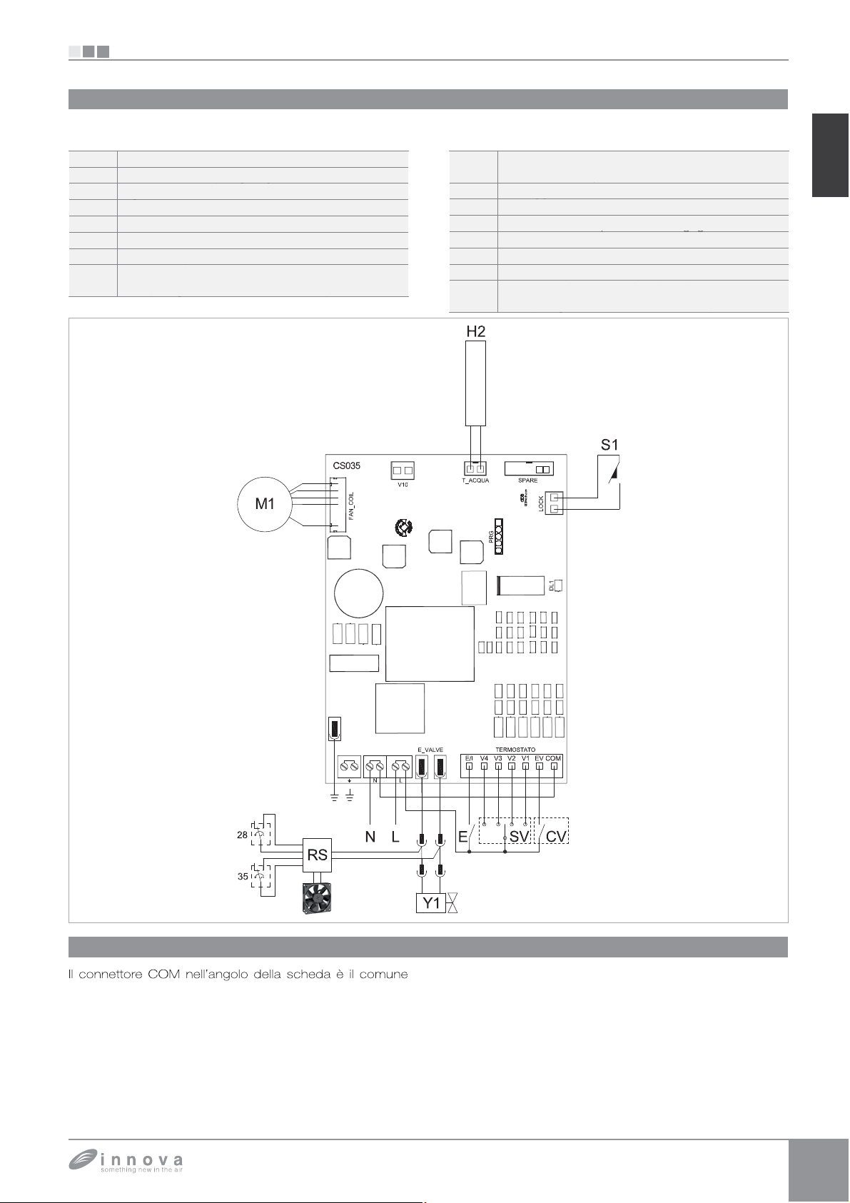
Schema connessioni BB0642 con termostati 3 velocità
seguire i collegamenti elettrici ad un termostato adatto allo
scopo secondo lo schema in fi
alimentazione elettrica 230V-50H
-
V1
V
V
elocità massima ventilator
elocità media ventilator
elocità minima ventilator
ingresso selezione riscaldamento, raffreddamento
Vedi paragrafo Gestione sonda acqu
elettrovalvola acqua calda (uscita in tensione a
30V/ 50Hz 1A
cablaggio versione R
motore ventilatore DC inverte
1
microinterruttore per sicurezza grigli
consenso termostat
V
selettore velocit
sonda temperatura acqua (2k
2*
posizionata nella batteria a bordo macchina.
edi paragrafo Gestione sonda ac
BB0642
IT
Collegamenti BB0642 con termostati a 3 velocità
5.5
a ponticellare al neutro N de
230V. L’ingresso
con ingesso aperto si pone in stand-by. Lo stesso dovr
ssere ponticellato al connettore L de
ettrica a 230V per attivare l'elettrovalvola.
I 4 ingressi velocit
connettore L de
ttivano il ventilatore, se l’ingresso
microinterruttore di sicurezza griglia risulta chiuso.
mentazione elettrica a
l’ ON/OFF della scheda la quale
V1, V2, V3 e V4, quando ponticellati
mentazione elettrica a 230V,
1 a cui è connesso
mentazione
a sequenza è velocità massima, pari a 1400rpm sul
connettore V1, velocit
V2, velocit
upersilent, 400rpm sul connettore V4.
n caso di chiusura contemporanea di pi
i porrà ad un numero di giri pari a quello imposto dalla
connessione con pi
’ possibile collegare più schede in parallelo ad un unico
termostato anche utilizzando diverse velocit
minima, 680rpm sul connettore V3 e velocit
media, 1100rpm sul connettore
ingressi il motore
alta velocit
.
Page 16
BB0642
ll
CQ
)
f
q
(
C
/
(
l’i
(
occo de
ensione alla scheda
5.6
SI
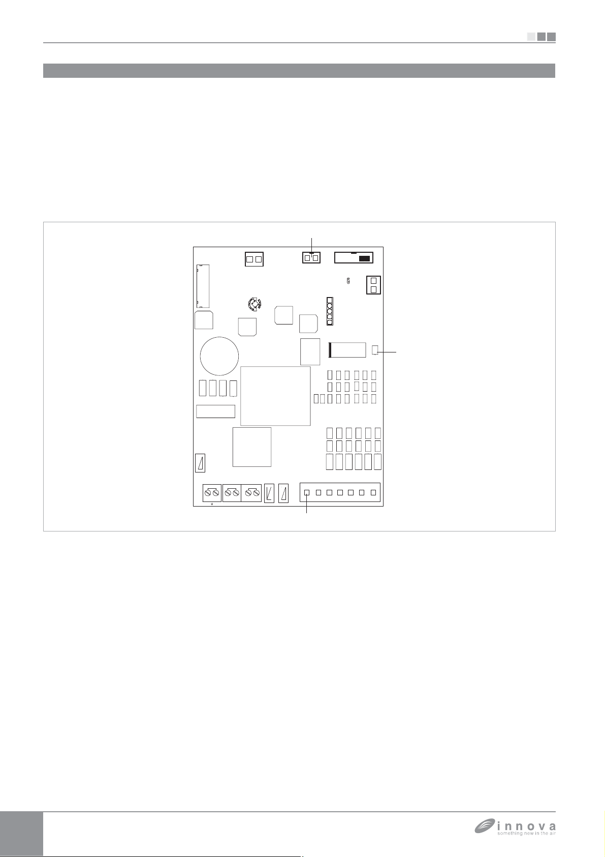
Gestione sonda acqua BB0642 con termostato 3 velocità
e la sonda di rilevazione della temperatura dell’acqua non viene
co
egata il ventilatore si avvia istantaneamente.
e la sonda presente sull’apparecchio posizionata nell’apposito
pozzetto della batteria viene collegata al connettore T_A
B
. la scheda esegue le funzioni minima temperatura acqua per il
UA (rif.
unzionamento in riscaldamento e massima temperatura acqua in
raffrescamento e
al funzionamento attivo
30°
in riscaldamento) la ventilazione viene arrestata e l’anomalia
uindi se la temperatura dell’acqua non è idonea
sopra i 20°C in raffreddamento, sotto i
segnalata dal singolo lampeggio + pausa del LED (rif. A).
La discriminante riscaldamento
raffrescamento viene attuata
CS 35
V1
AN COIL
attraverso l’ingresso E
asciando aperto
rif. C) della scheda:
ngresso la scheda si pone in riscaldamento;
chiudendolo in raffrescamento.
e dopo aver collegato la sonda la stessa viene scollegata
l’assenza viene segnalata con 3 lampeggi + pausa del LED
il bl
l funzionamento.
Per confermare il funzionamento privo di sonda togliere e ridare
t
.
uesta condizione verrà memorizzata dalla scheda per tutti i
successivi avvii.
In ogni caso nel momento in cui la sonda viene collegata si
ipristina il normale funzionamento con soglie di temperatura.
PRG
SPARE
GDBtech.com
LOCK
DL1
TACUA
rif. A)
E VALVE
LN
EI
TERMOSTATO
COMEVV1V2V3V4
Page 17
SI
0V
Y1
S
0
a
V
g p gg pp
)
)
S
gg
pgg
jump
bili
V
jp g
i
igli
l
.
(
.
.
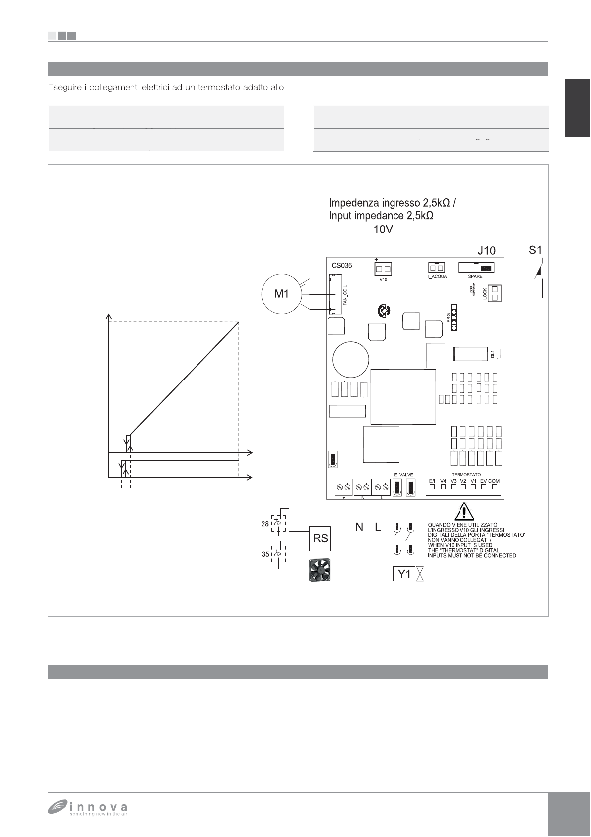
5.7
Schema connessioni BB0642 con termostati 0-10V
scopo secondo lo schema in figur
alimentazione elettrica 230V-50Hz
-
1
ingresso pilotaggio apparecchio 0÷10
lettrovalvola acqua calda (uscita in tensione a
230V/ 50Hz 1A
MAX rpm
BB0642
R
1
ablaggio versione R
otore ventilatore DC inverter
icrointerruttore per sicurezza griglia
er a
tazione ingresso 0÷10
IT
M1.
FAN COIL
MIN rpm
ON
Y1
OFF
0 1 10
0,9 1,1
V10 sign.
(V DC)
Collegamenti BB0642 con termostati 0-10V
5.8
L’ingresso 10V, se l’ingresso S1 a cui è connesso il
m
crointerruttore di sicurezza gr
elettrovalvola Y1 e regola il numero di giri del ventilatore in
a
ternativa ai 4 ingressi quando viene posizionato un jumper
tra i due PIN della porta SPARE
La “rampa” di velocità prevede una regolazione lineare dal
valore minimo
valori di tensione > = 1,1V÷10V DC. Il motore risulta spento
a risulta chiuso attiva
400rpm) a quello massimo (1400rpm) per
per valori inferiori ad 1V DC
elettrovalvola Y1 viene attivata per valori di tensione > 1V
C e si spegne quando la stessa scende sotto 0,9V DC
Page 18
BB0642 + BM1151
V
A
(
v
)
py)
pg g
g
V
)
(p)
V
)
(p)
V
)
(p)
p(p)
)
)
S
gg
r
pgg
ON/O
g
g
v
.
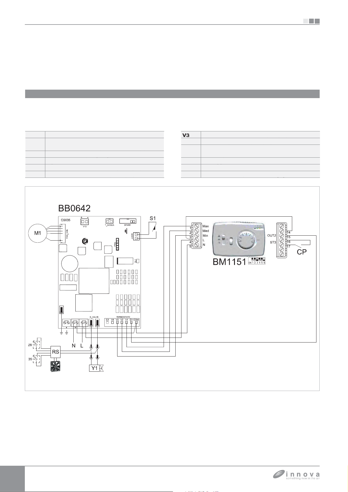
6.1
Schema connessioni BB0642 + BM1151
SI
BB0642 + BM1151
Il comando a parete BM1151II è un termostato di tipo
elettronico con selettore
selettore estate/inverno. Il comando deve essere accoppiato
con il controllo per re
L-
E
limentazione elettrica 230V-50Hz
ngresso sensore presenza
entilconvettore viene posto in stand-by.
Neutro comune per gli ingressi
M
Ingresso consenso
elocità massima ventilatore (1400rpm
elocità media ventilatore (1100rpm
olazione remota BB0642. Dispone di
FF, selettore a tre velocità e
se chiuso, il
na uscita in tensione per l'alimentazione di un'elettrovalvola e
di un in
resso sensore presenza (se chiuso, il ventilconvettore
iene posto in stand-by.)
elocità minima ventilatore (680rpm
Velocità supersilent (450rpm).
4
Y
lettrovalvola acqua (uscita in tensione a 230V/
50Hz 1A
ablaggio versione R
1
otore ventilatore DC inverte
icrointerruttore per sicurezza griglia
Page 19
SI
1
V2
3
Y1
S
Ali
Hz
pg g
g
Velocità massima ventilatore (1400rpm)
(p)
Velocità media ventilatore (1100rpm)
(p)
Velocità minima ventilatore (680rpm)
(p)
p(p)
V
)
p(p)
/
)
)
S
gg
C
igli
pgg
)
pq()
g
à
g
(
.
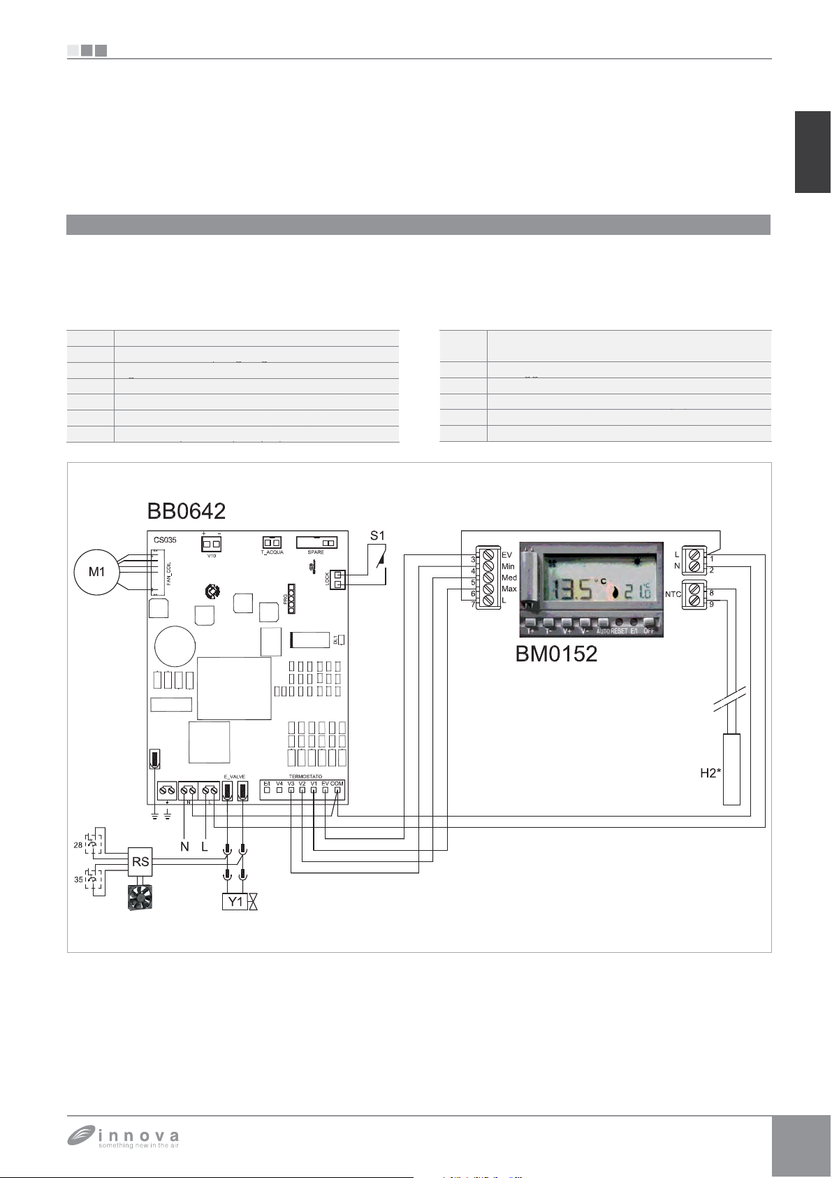
7.1
Schema connessioni BB0642 + BM1152
BB0642 + BM1152
BB0642 + BM1152
IT
Il kit comando ad incasso BM0152 permette di regolare
tutte le funzioni del ventilconvettore. E' dotato di un'uscita
in tensione per l'alimentazione di un'elettrovalvola. Attraverso
la sonda incorporata effettua la re
ambiente agendo sulle tre velocit
L-N
V
V
mentazione elettrica 230V-50
elocità supersilent (450rpm
olazione di temperatura
del ventilconvettore. Se
collegato alla sonda di temperatura dell’acqua posizionata
nel pozzetto posto sulla batteria dell’apparecchio
la funzioni di minima in riscaldamento (42°C) e massima
in raffrescamento
controllo per regolazione remota BB0642
lettrovalvola acqua (uscita in tensione a 230V
0Hz 1A
R
1
ablaggio versione R
motore ventilatore D
onda temperatura acqua ( 2kohm
osizionata nella batteria a bordo macchina
17°C). Va montato in accoppiamento al
inverter
crointerruttore per sicurezza gr
a
estisce
Page 20
o
BBBBB
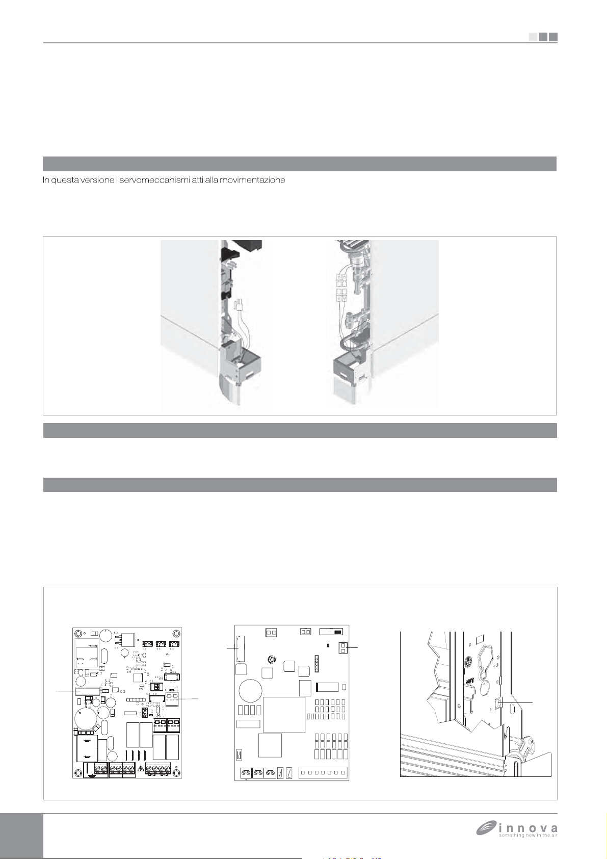
VERSIONI FULL FLAT, RS E CON ATTACCHI A DESTRA
S
/
.
A -
o
a
p
(
).
gli
ll’
grig
g
p
.
/
).
VERSIONI FULL FLAT, RS E CON ATTACCHI A DESTRA
8.1
Collegamenti versioni full flat
ella griglia sono precablati sull'apparecchio. Tramite un
pposito connettore è possibile collegarli all'uscita FF dei
pannelli EB0644 o ER0645.
elettromeccanico o un comando non originale collegare i
e viene utilizzato un termostato
ue terminali direttamente all'alimentazione elettrica 230V
0 Hz destinata all'elettrovalvola
al connettore elettrovalvola del comand
-alla testina dell’elettrovalvol
SI
A
8.2
Collegamenti versioni RS
Nelle versioni RS connettere l’apposito connettore rapido
all’uscita elettrovalvola Y1
elettronica
8.3
vedi paragrafi Connessioni
Collegamento motore nelle versioni con attacchi idraulici a destra
redisposta sulla scheda
el caso si renda necessario invertire la posizione de
attacchi idraulici della batteria dal lato sinistro a quello destro
e
apparecchio la scatola dei collegamenti elettrici viene
anch’essa invertita ma essendo il motore del ventilatore ed
il microinterruttore sicurezza
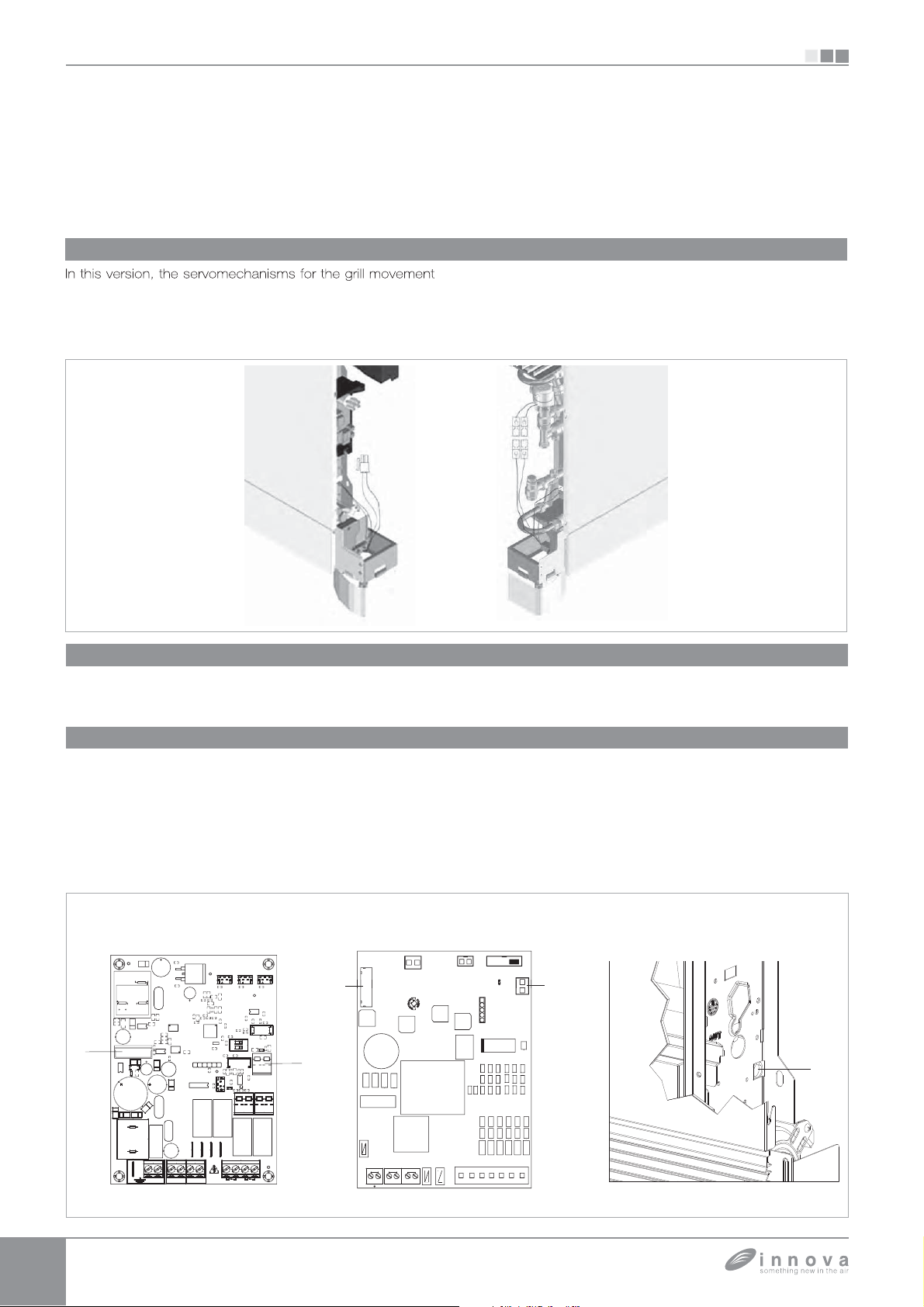
ori
inale si rende necessario utilizzare l’apposito kit BB0646
dis
onibile come accessorio
Il cavo, dotato di connettori maschio
lia vincolati nella posizione
femmina va collegato
B
el lato destro al motore e nel lato sinistro al connettore
apido del motore presente sulla scheda (rif.D).
noltre i due terminali provenienti dal microinterruttore
icurezza griglia vanno prolungati e connessi nel lato sinistro
l contatto S1 presente sulla scheda (rif.E
cavi vanno fatti passare nella parte posteriore
ell’apparecchio attraverso lo specifico foro (rif.C).
NC
NC
PRI
+
MOTOR
4
1
SEC
AUX
+
+
23
12 2112
LN
RSKD
-+
AUX
EV2NEV1N
SW1
1
RS485
REMOTE
ON
B
A
ZOT
41
SW GRL
211221
BA
4321
BOILERCHILLER
CS 35
AIRH2H4
SW2
V1
AN COIL
E VALVE
LN
TACUA
EI
PRG
TERMOSTATO
SPARE
DBtech.c
GDBtech.com
LOCK
DL1
COMEVV1V2V3V4
Page 21

Installation manual
EN
EB0644 - ER0645 - EM0649 - EB0647 - ER0648
EB0643
BB0642 - BM1151- BM0152
Page 22

We would first of all like to thank you for having chosen one of our products.
We are sure you will be happy with it because it represents the state of the art in the technology of
home air conditioning.
By following the suggestions contained in this manual, the water-water heat pump that you have
purchased will operate without problems giving you optimum room temperatures with minimum
energy costs.
Symbols
The pictograms in the next chapter provide the necessary
information for correct, safe use of the machine in a rapid,
Editorial pictograms
User
U
- Refers to pages containing instructions or information
for the user.
Installer
I
- Refers to pages containing instructions or information
for the installer
Safety pictograms
Generic danger
- Signals to the personnel that the operation described
could cause physical injury if not performed according
to the safety rules.
Danger of high voltage
- Signals to the personnel that the operation described
could cause electrocution if not performed according to
the safety rules.
unmistakable way
Service
S
- Refers to pages containing instructions or information
for the installer TECHNICAL CUSTOMER SERVICE.
Danger due to heat
- Signals to the personnel that the operation described
could cause burns if not performed according to the
safety rules.
Do Not
- Refers to actions that absolutely must not be
performed.
Page 23

1
1.1 4
General warnings ...............................................................
Generale
2 EB0644 - ER0645 - EB0647 - ER0648
2.1 5
2.2 5
2.3 6
2.4 6
2.5 7
2.6 7
2.7 8
2.8 9
Mounting, setting and connection of on-board machine control panels EB0644, ER0645, EB0647, ER0648 . .
Mounting .....................................................................
Setting auxiliary functions dip-switches A and B .........................................
CP presence contact input connection ...............................................
Mounting air temperature probe (only for models EB0644 and EB0647) .......................
Setting automatic cooling/heating regulation system......................................
EB0644 and EB0647 connections ..................................................
ER0645 and ER0648 connections ..................................................
3 EM0649
3.1 10
3.2 11
3.3 11
Fitting and connecting the wall-mounted remote control panel EM0649 .......................
EM0649 connections ............................................................
CP presence contact input connection ...............................................
4 EB0643
4.1 12
4.2 12
4.3 13
4.4 13
4.5 13
EB0643 machine onboard control assembly and connecting ...............................
Mounting .....................................................................
Mounting air temperature probe ....................................................
EB0643 connections ............................................................
Water probe management kit EB0643................................................
EN
5 BB0642
5.1 14
5.2 14
5.3 14
5.4 15
5.5 15
5.6 16
5.7 16
5.8 17
Mounting and connecting the fan control for remote adjustment BB0642 ......................
Mounting .....................................................................
LED signals ...................................................................
Diagram for BB0642 connections with 3-speed thermostats ...............................
BB0642 connection with 3-speed thermostats .........................................
Water probe management BB0642 with 3-speed thermostats . . . . . . . . . . . . . . . . . . . . . . . . . . . . . .
Diagram for BB0642 connections with 0-10V thermostats .................................
BB0642 connections with 0-10V thermostats ..........................................
6 BB0642 + BM1151
6.1 18
BB0642 + BM1151 connections diagram .............................................
7 BB0642 + BM1152
7.1 19
8
8.1 20
8.2 20
8.3 20
BB0642 + BM1152 connections diagram .............................................
Full flat, RS and connection on the right side versions
Full flat versions connection ....................................................... 20
RS versions connection .......................................................... 20
Water connection on the right side versions motor connection .............................. 20
Page 24
GENERAL
1.1
General warnings
These instructions are an integral part of the booklet of
the device on which the kit will be installed. Refer to the
booklet for general warnings and fundamental safety
rules.
This manual is dedicated exclusively for the qualified,
authorised installation technician who must be
adequately trained and possess all the necessary
psychophysical requirements requested by law.
All the operations must be performed with care and
good workmanship in compliance with the safety at
work regulations in force.
After unpacking, make sure that all the components are
present. If not, contact the agent who sold the appliance
to you.
SIU
GENERAL
It is forbidden to modify the safety or adjustment devices
or adjust without authorisation and indications of the
manufacturer.
It is forbidden to dispose of, or leave in the reach of
children, the packaging materials which could become
a source of danger.
All repair or maintenance interventions must be performed
by the technical service department or by professionally
qualified personnel as foreseen in this booklet. Do not
modify or intervene on the appliance as this could create
dangerous situations and the manufacturer will not be
responsible for any damage caused.
Page 25
SI
T
g
.
/
pp
To
(
(
f
(
f
cooler-convecto
)
(
);
(MOTOR)
(
t
jump
ersions
;
;
f
(
). C
ly i
.
d
(
G);
(
);
C
-
;
l;
p
;
f
.
EB0644 - ER0645 - EB0647 - ER0648
Mounting, setting and connection of on-board machine control panels EB0644,
ER0645, EB0647, ER0648
2.1
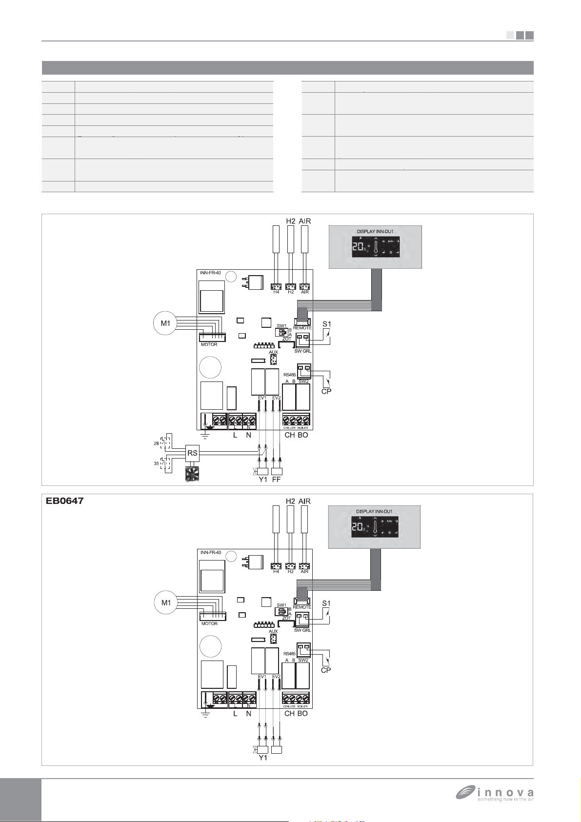
he controls have two independent free contacts to control
a chiller and a boiler and a presence input. The 2-pipe
versions have a 230V output for powerin
2.2
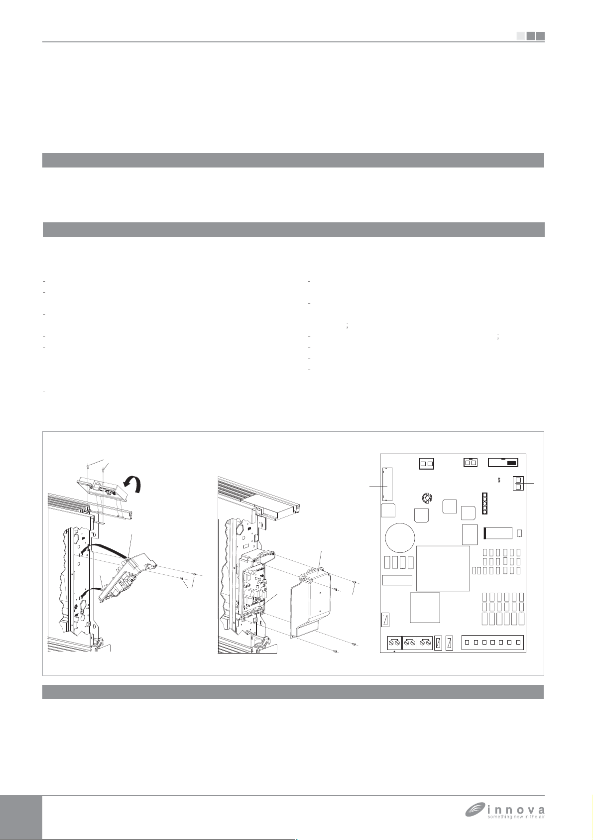
Mounting
the summer
EB0644 - ER0645 - EB0647 - ER0648
EN
and winter solenoid valve while the 4-pipe versions have
2 independent 230V outputs to power a summer solenoid
valve and a winter solenoid valve
Place the control panel into its housing in the upper part of
the cooler-convector
su
lied screws (ref. A).
cooler-radiator and fix it with the two
install the connection box:
open the box (ref. B);
insert the lower lug into the special slot
ref. C) on the
ide of the appliance;
hook the upper part of the box to the side
ix it with the two supplied screws
ref. E);
ref. D);
ix the earth wire to the
structure using the supplied screws
the minimum
force of about 2N must be used when screwing-up
connect the rapid connector on the motor
to that on the board
ref. I) *;
he 2 terminals of the SW GRL clamp (ref. L) feature a
er that ensures the operation of the SLI and RSI
v
without microswitch.
or the other versions remove the jumper and connect
r
ref. M
the two terminals from the grid safety microswitch. *
connect the water probe connector (ref. F) on the
ooler-convector/cooler-radiator
the water temperature probe checks the temperature
inside the batteries and determines the start o
fan based on the set parameters
maximum summer functions
correct
n the well on the battery
minimum winter and
heck that it is inserted
the
ake the electrical connections, order the wiring an
fix the wires using the 3 supplied clamps
close the box and fix with the 4 screws
ount the aesthetic side panel on the
convector/cooler-radiator
ref.
ref. H
ooler
tighten the upper screw on the control pane
lace the screw cover into the slot on blind
anel
or versions with hydraulic connections on the right
re
er to the relevant paragraph
NC
NC
PRI
+
MOTOR
4
1
SEC
AUX
+
+
23
12 2112
LN
-+
AIRH2H4
SW1
1
REMOTE
ON
B
A
ZOT
RSKD
41
AUX
SW GRL
211221
RS485
BA
SW2
EV2NEV1N
4321
BOILERCHILLER
Page 26
EB0644 - ER0645 - EB0647 - ER0648
A
A
Th
l
f
.
:
r
pp
y
p
p
O
.
(
osed a
users connected
f
2.3
Setting auxiliary functions dip-switches A and B
SI
ere are two dip-switches on the electronic control pane
or setting the functions of the appliance as required
Use cursor A to modify the night function logic
In the ON position the ventilation is inhibited thus letting
the machine heat the room through natural radiation o
convection as ha
FF position the fan functions normall
CP presence contact input connection
2.4
When the contact connected to the SW2
l
ll the
ens with traditional radiators; in the
.
ref. C) input is
will be switched off.
SEC
SEC
NC
NC
NC
NC
PRI
PRI
AUX
AUX
+
+
MOTOR
MOTOR
+
+
RSKD
RSKD
-+
-+
AUX
AUX
SW1
SW1
1
1
ZOT
ZOT
et cursor B to ON (in cooling only) to enable the
continual ventilation at the minimum s
the set
oint has been reached to ensure a more
regular functioning of the temperature probe. Passing
to heating will cancel this condition; set the cursor set
to
FF to disable this function
The input cannot be connected in parallel to one o
another electronic board (use separate contacts).
AIRH2H4
AIRH2H4
SW1
SW1
1
1
ON
ON
B
B
REMOTE
REMOTE
ON
ON
B
B
A
A
41
41
SW GRL
SW GRL
eed, even after
4
4
23
23
1
1
12 2112
12 2112
+
+
LN
LN
211221
211221
RS485
RS485
BA
BA
SW2
SW2
EV2NEV1N
EV2NEV1N
4321
4321
BOILERCHILLER
BOILERCHILLER
Page 27
SI
C)
W
y
h
l
g
th
Thi
f
p
f
g
g
g
high
both
p
C
g
ff
g
2.5
Mounting air temperature probe (only for models EB0644 and EB0647)
- pass the probe through the hole on the shoulder (ref. B)
EB0644 - ER0645 - EB0647 - ER0648
nsert the probe in the lower hole (ref.
- fix the probe in the spcial hook (ref. D).
EN
Setting automatic cooling/heating regulation system
2.6
hen set to this condition the control can automaticall
c
oose between cooling or heating, excluding the norma
manual selection. This settin
e 4-pipe versions.
ctivated by an authorised installer or quali
To activate this function, kee
pressed
p simultaneously. To return a
nly or heating only condition press the sum/win button
ref. A) for 10 seconds until the blue and red LEDs switch
or 10 seconds until the blue and red LEDs li
is particularly useful for
s regulation system can only be
ied technician.
the sum/win button (ref. A)
ain to the manual coolin
ht
ff. Press the button again to select the winter function.
heck the functioning of the Red LED (alight when the
etpoint is
witched off when the set
win button once to select the summer function.
functionin
lower than the room temperature, both switched o
the setpoint is hi
ven if there is a power black-out.
er than the room temperature,
oint is lower). Press the sum/
heck the
of the Blue LED (alight when the setpoint is
her). This selection will be maintained
when
Page 28
EB0644 - ER0645 - EB0647 - ER0648
be
pp
)
pp()
pp
r
(
)
(
)
pppy
pppy
)
gp( )
)
)
)
)
g
g
2.7
EB0644 and EB0647 connections
SI
I
M1
1
1
L-N
EB0644
ot water temperature pro
cold water temperature probe (*
fan motor DC inverte
ot water solenoid valve
owered output
cold water solenoid valve
owered output) (*
230V/50Hz electrical power supply connection
230V/50Hz 1A
230V/50Hz 1A
H4
boiler go-ahead output (free contact max 1A
chiller go-ahead output (free contact max
H
1A
output for servomotor mobile aspiration panel
230V/50Hz 1A powered output
presence sensor input (if closed, the fan coil
P
oes into stand-by.
S version wirin
nly present in the EB0647 panel for 4-pipe
versions.
H4
Y2
Page 29
SI
A-B
Y2
O
S
5
8
)
(p p )
pp
pp()
r
)
)
pppy
gp( )
)
gp( )
)
)
)
)
n
versions
T
f
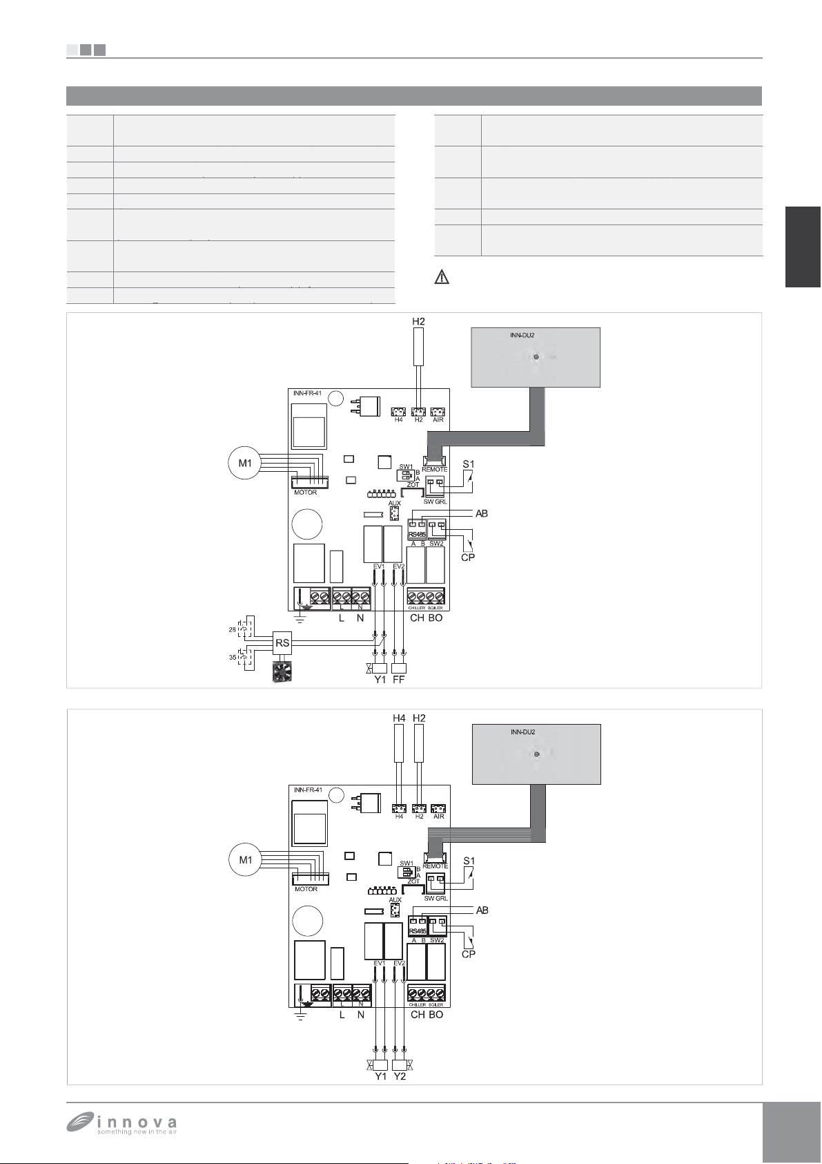
2.8
ER0645 and ER0648 connections
EB0644 - ER0645 - EB0647 - ER0648
4
M
LB
ER064
erial connection for wall-mounted remote
control EM0649 (respect the A-B polarisation
hot water temperature probe
fan motor DC inverte
hot water solenoid valve (230V/50Hz 1A
owered output
cold water solenoid valve (230V/50Hz 1A
owered output) (*
boiler go-ahead output (free contact max 1A
H
R
hiller go-ahead output (free contact max
1A
utput for servomotor mobile aspiration panel
230V/50Hz 1A powered output
resence sensor input (if closed, the fan coil
oes into stand-by.
version connectio
nly present in the ER0648 panel for 4-pipe
.
he control panel can be operated even if without
INN-DU2 inter
ace.
EN
4
Page 30
EM0649
T
(
w
(
)
g
T
y
t
:
);
(
(
(
;
(
A
(
3.1
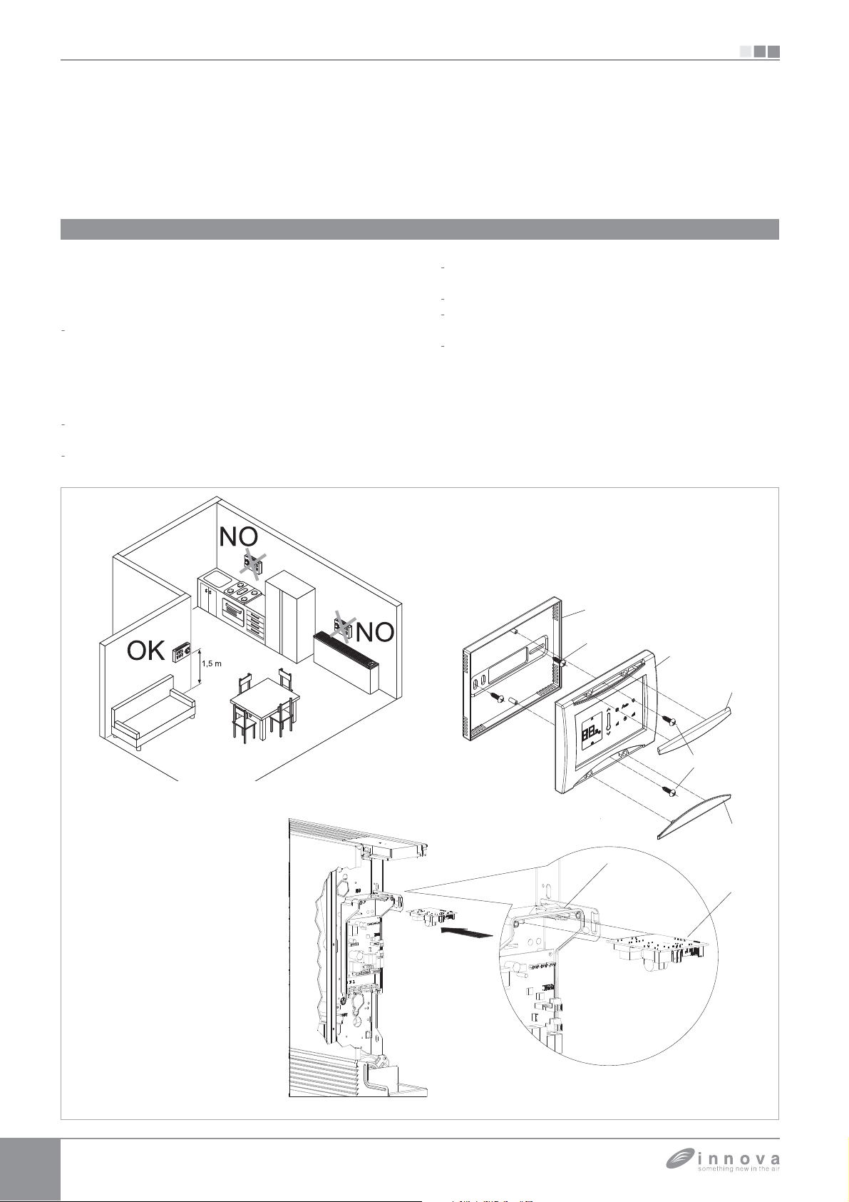
Fitting and connecting the wall-mounted remote control panel EM0649
he wall-mounted EM0649 is an electronic thermostat
ith temperature probe) with the possibility of controlling one
r more cooler-convector/cooler-radiators (up to a maximum
f 30) equipped with electronic control for allowing remote
control ER0645 or ER0648.
Install the wall-mounted remote control EM0649 away
from doors or windows and sources of heat
convectors, stoves, direct sunlight
at a hei
he wall-mounted remote control is alread
he package so follow the following mounting instructions
open the cover by levering the two lower lugs with a
crewdriver (ref. E and F
ht of about 1.5 m from the floor.
nscrew the two fixing screws on the electronic
, on internal walls
heaters,
assembled in
EM0649
fitted
boards at the base of the control
use the base of the control
point on the wall
drill the holes in the wall;
route the electric wires through the windows on the
base
fix the base of the control to the wall using suitable
plugs
ref. B).
230/12 VDC PCB transformer (ref. H) is supplied for the
lectric power supply of the control that should be installed
in the connection box
quipped with electronic control for allowing remote control
R0645 or ER0648.
use the two opposite holes);
ref. G) on board of one of the devices
ref. D);
ref. A) to trace the fixing
SI
Page 31
SI
p
.
(up
w
S
g
he lead
;
(
p
f
);
p
/
t
;
w
/
3.2
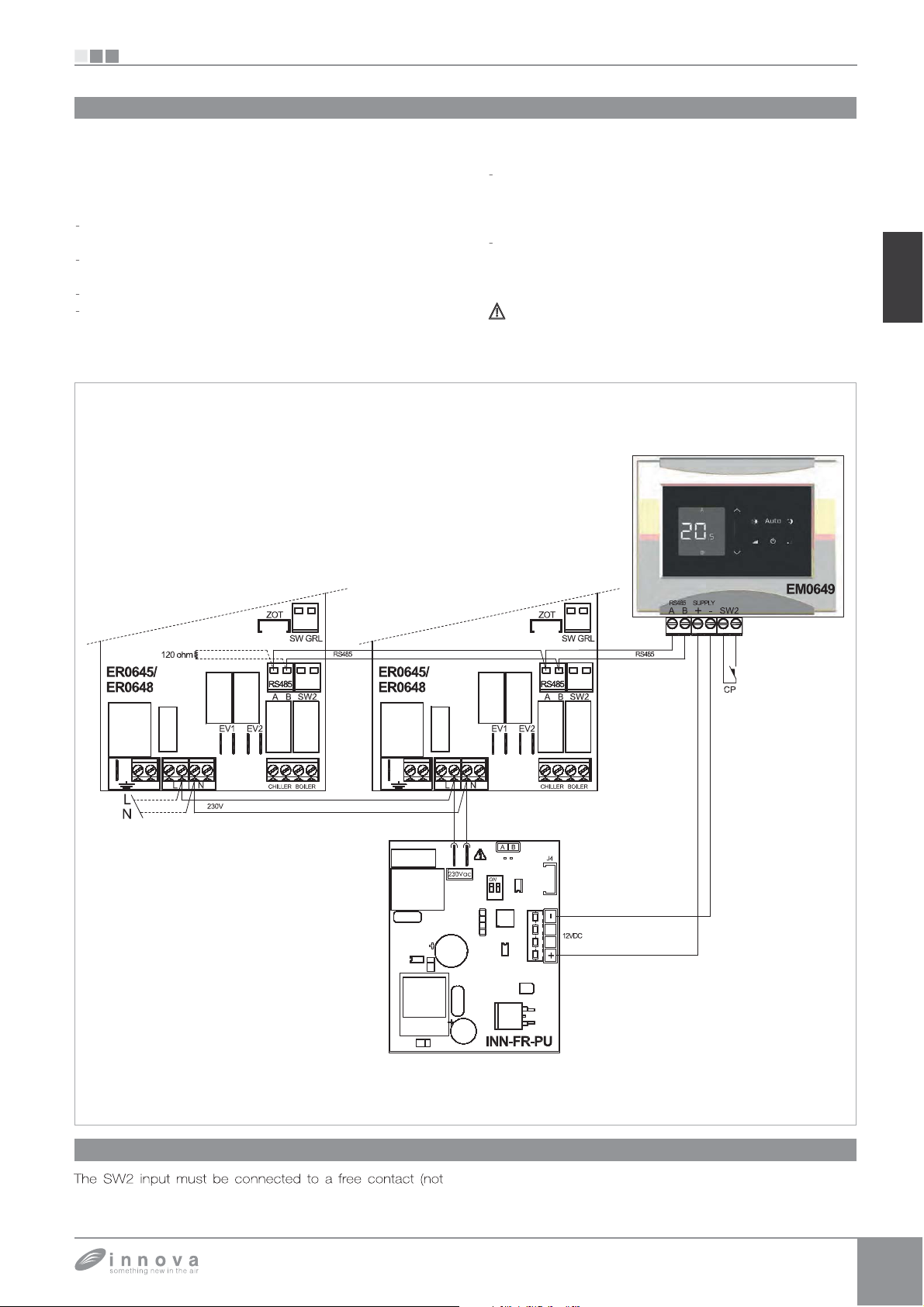
EM0649 connections
EM0649
onnect the RS485 line of the wall-mounted remote control
to one or more
ith electronic remote control ER0645 or ER0648 through a
bipolar cable suitable for R
eparate from power supply cables.
hase out the wall in order to minimise the len
t
complete the line with the 120 ohm resistance
supplied;
do not make "star" connections
the connection with cable RS485 is polarised, observe
the indications “A” and “B” on each peripheral device
connected
s;
to a maximum of 30) units equipped
485 serial connection, keeping it
for the connection it is preferable to use a
th of
bi
olar shielded cable with a minimum section o
mm2
onnect the terminals of the 230V
f power supply board 230
o clamps L and N of board INN-FR-41 of control
0645 or ER0648
onnect the power SUPPLY terminals + and - of the
all-mounted control EM0649 to the 230
power supply board, observing the polarity.
ower the remote control solely with the 230/12 VDC
power supply board provided.
12VDC INN-FR-B3
ower supply
0.35
12VDC
EN
CP presence contact input connection
3.3
allowing remote control ER0645 or ER0648 connected will
owered) and, when the contact is closed the remote
control
anel EM0649 and all the electronic control for
be switched off
Page 32
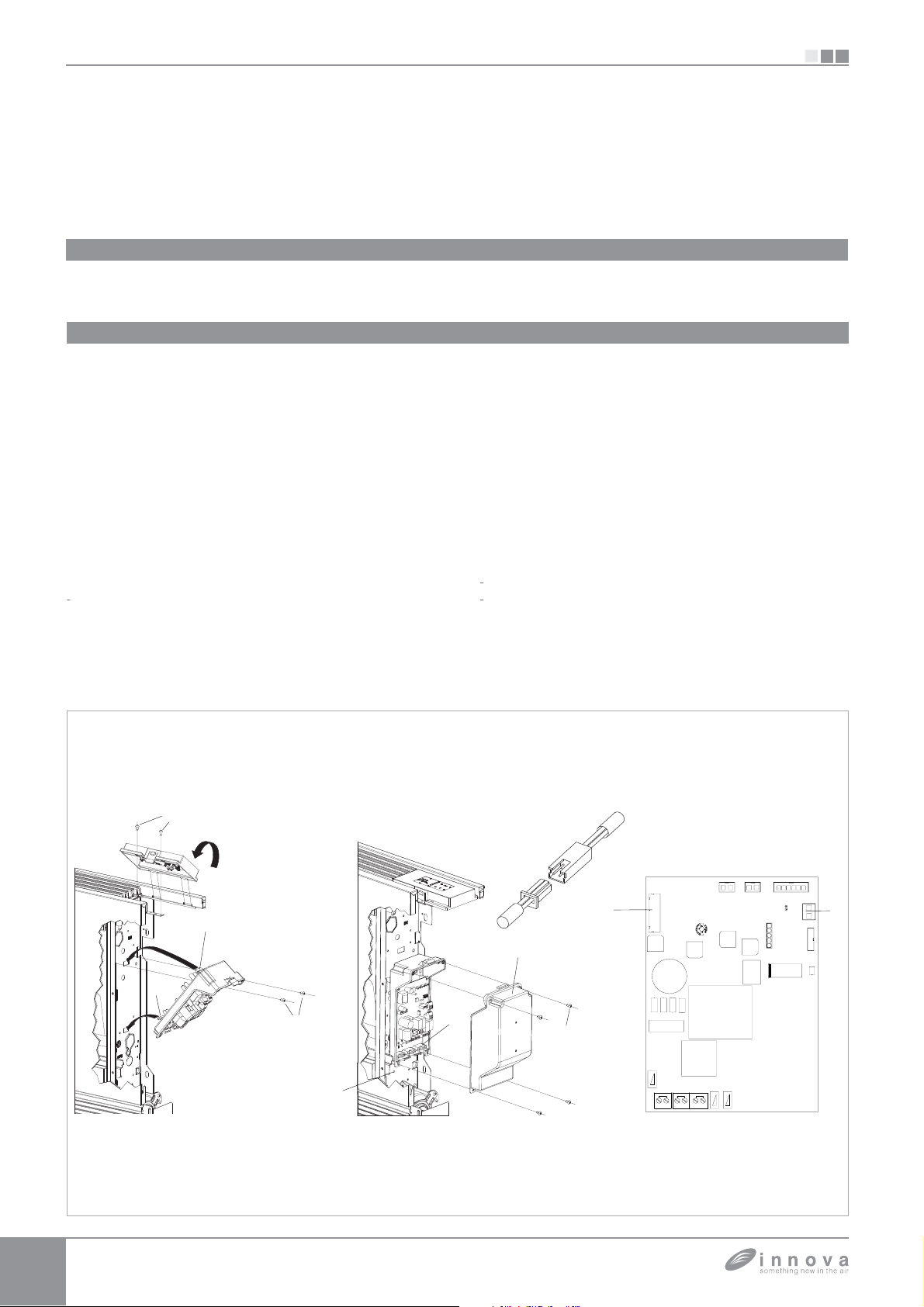
EB0643
g
t
).
To i
:
;
(
;
g
);
(
(
;
p (
jump
versions
jump
g
;
b
ly i
g
C
/
;
p
g
g
T
/
.
4.1
EB0643 machine onboard control assembly and connecting
he on-board machine control with speed selector and ON
OFF button, thermostat adjustable between 5 and 40°C,
summer/winter selector and minimum winter temperature
Mounting
4.2
Place the control panel into its housin
in the upper part of
he cooler-convector/cooler-radiator and fix it with the two
upplied screws (ref. A
nstall the connection box
- open the box (ref. B)
insert the lower lug into the special slot (ref. C) on the
ide of the appliance;
ook the upper part of the box to the side
ref. D);
- fix it with the two supplied screws (ref. E)
fix the earth wire
ref. M) to the cooler-convector
tructure using the supplied screws (the minimum force
of about 2N must be used when screwin
connect the rapid connector on the motor
to that on the board
ref. I) *
the 2 terminals of the LOCK clam
-up
FAN_COIL)
ref. L) feature a
er that ensures the operation of the SLI and RSI
without microswitch.
For the other versions remove the
er and connect
EB0643
(30°C) and maximum summer temperature function (20°C)
is suitable for installation onboard and has a 230 V output for
olenoid valve control
the two terminals from the
rid safety microswitch. * ;
connect the water probe connector (ref. F) on the
Cooler-convector/cooler-radiator
the water temperature pro
e checks the temperature
inside the batteries and determines the start of the
fan based on the set parameters (minimum winter and
maximum summer functions). Check that it is inserted
correct
-
ake the electrical connections, order the wiring and
fix the wires usin
n the well on the battery;
the 3 supplied clamps (ref. G);
close the box and fix with the 4 screws (ref. H);
ount the aesthetic side panel on the
convector
cooler-radiator
tighten the upper screw on the control panel;
lace the screw cover into the slot on blind
anel;
or versions with hydraulic connections on the ri
refer to the relevant para
raph.
SI
ooler-
ht
CS 35
FAN_COIL
T_ARIA
E_VALVE
T_ACQUA SPARE
PRG
GDBtech.com
LOCK
DISPLAY
DL1
Page 33
SI
A
3
T
):
(
)
C)
w
e
pp
f
w
)
p)
n
pppy
n
be
pp
p
y p
g
g
pp
p
/
y
.
p
.
p
p
g
g
g
g
4.3
Mounting air temperature probe
EB0643
o position the temperature probe (ref. A
pass the probe through the hole on the shoulder
EB0643 connections
4.4
H
M
ater temperature prob
an motor DC inverter
rill safety micro-switch
1
ater solenoid valve (230V/50Hz 1A powered
output
ref. B
nsert the probe in the lower hole (ref.
fix the probe in the
230V/50Hz electrical power supply connectio
-N
special hook (ref. D).
version connectio
IR
r temperature pro
EN
EB064
CS 35
M1
28
Water probe management kit EB0643
4.5
RS
35
If the board detects the water tem
batter
ocket on the appliance, start-up takes place
FAN_COIL
H2AIR
T_ACQUA SPARE
T_ARIA
GDBtech.com
PRG
E_VALVE
LN
1
erature probe, in the
LOCK
DISPLAY
DL1
ormally. If the probe is not connected, its absence is
si
nalled with the red and blue LEDs flashin
and the a
To confirm o
liance will not start.
erations without the probe, press the summer
simultaneously
winter button for 5 seconds (ref A). This condition is stored
b
the board for all subsequent start-ups
DISPLA CS 4
S1
n any case, once the probe is connected normal operations
are restored with tem
erature thresholds
f the machine runs with the probe connected and the water
tem
erature is not suitable for active o
in coolin
and the fault is si
or below 30°C in heating), ventilation is stopped
nalled by the flashing of the corresponding
ED of the selected function (blue coolin
erations (above 20°C
C or red heatin
Page 34
BB0642
f
S
g
t
.
To i
:
)
f
)
/
g
;
p (
jump
v
f
h
d;
g
g
)
;
g
g
)
g
p
g
(
g
g
g
p
y
5.1
SI
BB0642
Mounting and connecting the fan control for remote adjustment BB0642
Mounted on board the machine, it manages the motor with
ixed speed; it can only be installed on the
L and SLI versions
nd can be connected to controls with an thermostat or any
5.2
Mounting
Place the control panel into its housin
in the upper part of
he cooler-convector/cooler-radiator and fix it with the two
upplied screws (ref. A)
nstall the connection box
open the box
nsert the lower lug into the special slot
ref. B)
ref. C)
ide of the appliance;
ook the upper part of the box to the side
ix it with the two supplied screws
ref. E
fix the earth wire to the cooler-convector
ref. D
cooler-radiator
tructure using the supplied screws (the minimum force
of about 2N must be used when screwin
the 2 terminals of the LOCK clam
-up)
ref. I) feature a
er that ensures the operation of the SLI and RSI
on the
other controls available on the market.
ersions without microswitch.
or the other versions remove the jumper and connect
the two terminals
rom the grid safety microswitch. * ;
onnect the rapid connector on the motor (FAN_COIL)
to t
at on the boar
ake the electrical connections, order the wirin
the wires usin
lose the box and fix with the 4 screws
the 3 supplied clamps
(ref. F)
ref. G
ount the aesthetic side panel on the Cooler-convector/
ooler-radiator
tighten the upper screw on the control panel;
or versions with hydraulic connections on the ri
refer to the relevant para
CS 35
AN COIL
V1
raph.
TAC UA
PRG
SPARE
GDBtech.com
and fix
ht
LOCK
5.3
LED signals
The LED (ref. A) is off if input CV is not closed (stand-by
condition
It is switched on upon closure of contact CV and si
standard o
It emits a sin
unsuitable water
2 flashes + pause for motor alarm (for example, jammin
.
nals
eration.
le flash + pause for fan stop alarm due to
with H2 water probe connected).
due
E VALVE
LN
to forei
n bodies, fault in the rotation sensor, activation of the
protective microswitch due to the filter cleanin
3 flashes +
fault
.
ause for water probe alarm disconnected or
DL1
TERMOSTATO
EI
COMEVV1V2V3V4
operation).
Page 35
SI
2
V3
Y1
g
e
f
C
i
d
f
f
S
V
V
.
d.
h
y
pppy
s
p
p
p
p
p
pp
gpgp
ph
gpgp
g
)
)
g
g
r
h
t
p
k
pp(
S
W
ph
pgpgp
5.4
Diagram for BB0642 connections with 3-speed thermostats
suitable for the purpose, accordin
230V-50Hz electric power suppl
-
common neutral for the input
V1
V
V
heating, cooling selection input. See Water probe
management paragra
to the diagram in the
ctur
hot water electrovalve (outlet with a volta
30V/50Hz 1A
RS version wirin
inverter DC fan moto
1
rid safety microswitc
thermostat consen
V
speed selector
water temperature probe (2
2*
located in the battery on the machine.
ater probe management paragra
BB0642
e of
EN
ee the
BB0642 connection with 3-speed thermostats
5.5
The COM connector on the corner of the board is the
common to be bridged to neutral N o
supply. The
goes
nto stand-by with the input open. It must be bridge
to connector L of the 230V electric power supply to
ctivate the electrovalve.
The 4 inputs o
to connector L o
the fan, if input
s connected is closed. The sequence is at maximum
V input is the ON/OFF of the board, which
speeds V1, V2, V3 and V4, when bridged
the 230V electric power supply, activate
1 to which the grid safety microswitch
the 230V power
peed, equal to 1400rpm on connector
peed, 1100rpm on connector
80rpm on connector V3 and supersilent speed, 400rpm
n connector V4
n the event of simultaneous closure of several inputs, the
otor will run at a number of revolutions equal to that set
y the connection with the highest spee
ne can connect several boards in parallel to a single
t
ermostat, even using several speeds.
2, minimum speed,
1, medium
Page 36
BB0642
i
p
y
p
CQ
t
)
(
).
T
(
T
T
5.6
SI
Water probe management BB0642 with 3-speed thermostats
If the water temperature detection probe is not connected the fan
starts
mmediately.
If the water tem
starts immediatel
If the
robe fitted on the device and positioned in the relevant battery
well is connected to the T_A
erature detection probe is not connected the fan
.
UA (ref. B) connector, the board
runs the minimum water temperature functions for the heating mode
and the maximum water temperature functions in the cooling mode;
herefore if the water temperature is not suitable for active operation
above 20°C during the cooling mode, under 30°C in the heating
mode
ventilation is stopped and the anomaly is signalled by a single
CS 35
V1
AN COIL
flash + pause of the LED
ref. A
he heating/cooling discriminant is implemented through the E input
ref. C) of the board: by leaving the input open, the board goes into
eating mode; by closing it, it goes into cooling mode.
f after having connected the probe it is disconnected, its absence
is signalled with 3 flashes + 1 pause of the LED
ref. A) and by the
eration block.
o confirm operation without the board disconnect and reconnect
the board power.
his condition will be stored by the board for all subsequent start-ups.
n any case, when the probe is connected, normal operation is
esumed with temperature thresholds.
PRG
SPARE
GDBtech.com
LOCK
DL1
TACUA
E VALVE
LN
EI
TERMOSTATO
COMEVV1V2V3V4
Page 37
SI
0V
Y1
S
0
i
e
f f
f
.
T
f
(
g
C.
g
C.
pply
pppy
V
pp
)
)
g
g
h
bling jump
V
pgjp
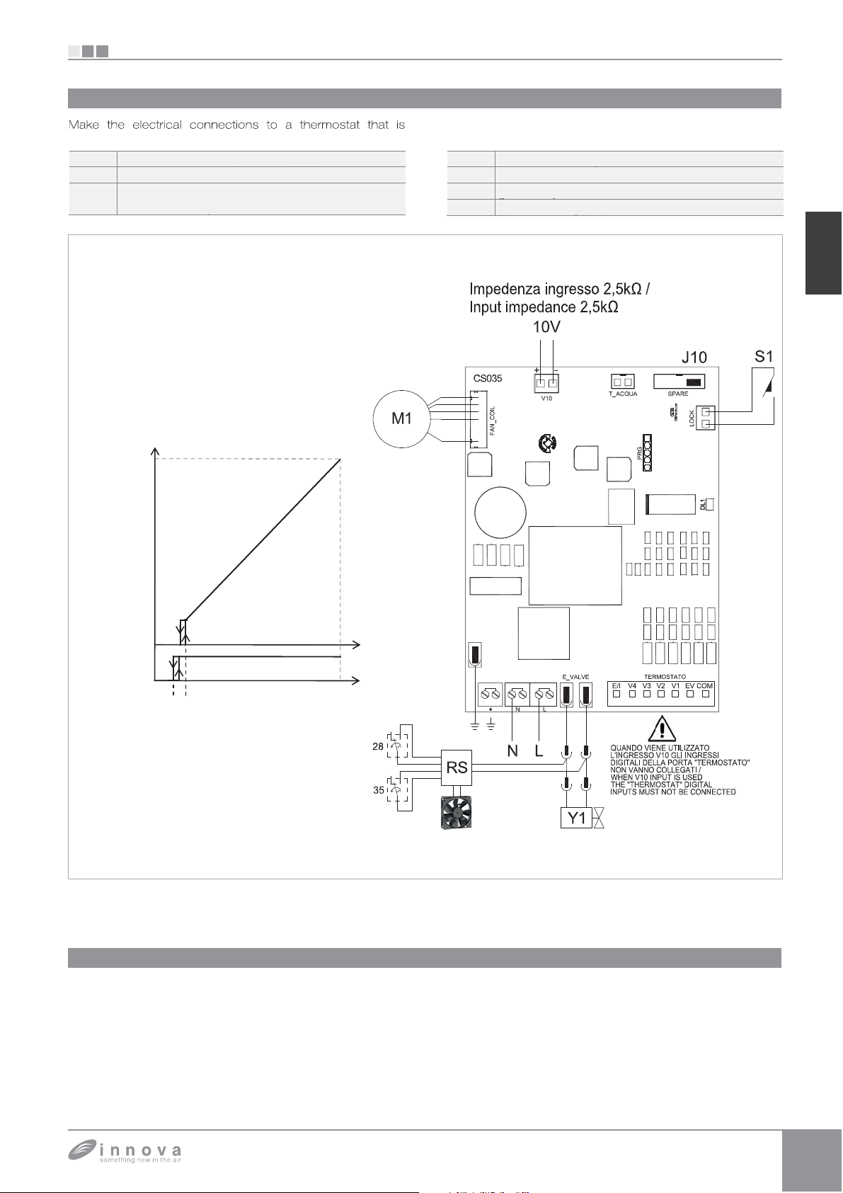
5.7
Diagram for BB0642 connections with 0-10V thermostats
suitable for the purpose, according to the diagram in the
230V-50Hz electric power su
-
1
device pilot input 0÷10
hot water electrovalve (outlet with a voltage of
230V/50Hz 1A
MAX rpm
BB0642
p
ctur
R
1
version wirin
inverter DC fan motor
rid safety microswitc
nput ena
er 0÷10
EN
M1.
FAN COIL
MIN rpm
ON
Y1
OFF
0 1 10
0,9 1,1
V10 sign.
(V DC)
BB0642 connections with 0-10V thermostats
5.8
The 10V input, if input S1 to which the grid safety microswitch
s connected is closed activates the Y1 solenoid valve and,
adjusts the number o
inputs, when a jumper is
SPARE port
he speed “ramp” provides a linear adjustment
minimum value
for volta
e values > = 1,1V÷10V DC. The motor is off with
an revolutions alternatively to the 4
itted between the two PINs of the
400rpm) to the maximum value (1400rpm)
rom the
values below 1V D
The Y1 valve is enabled by volta
when the same falls below 0.9V D
e > 1V DC and turns off
Page 38
BB0642 + BM1151
V
pply
pp y
)
p
)
p( p)
)
p( p)
)
p(p)
pp(p)
g
)
)
r
h
T
t
/
t
).
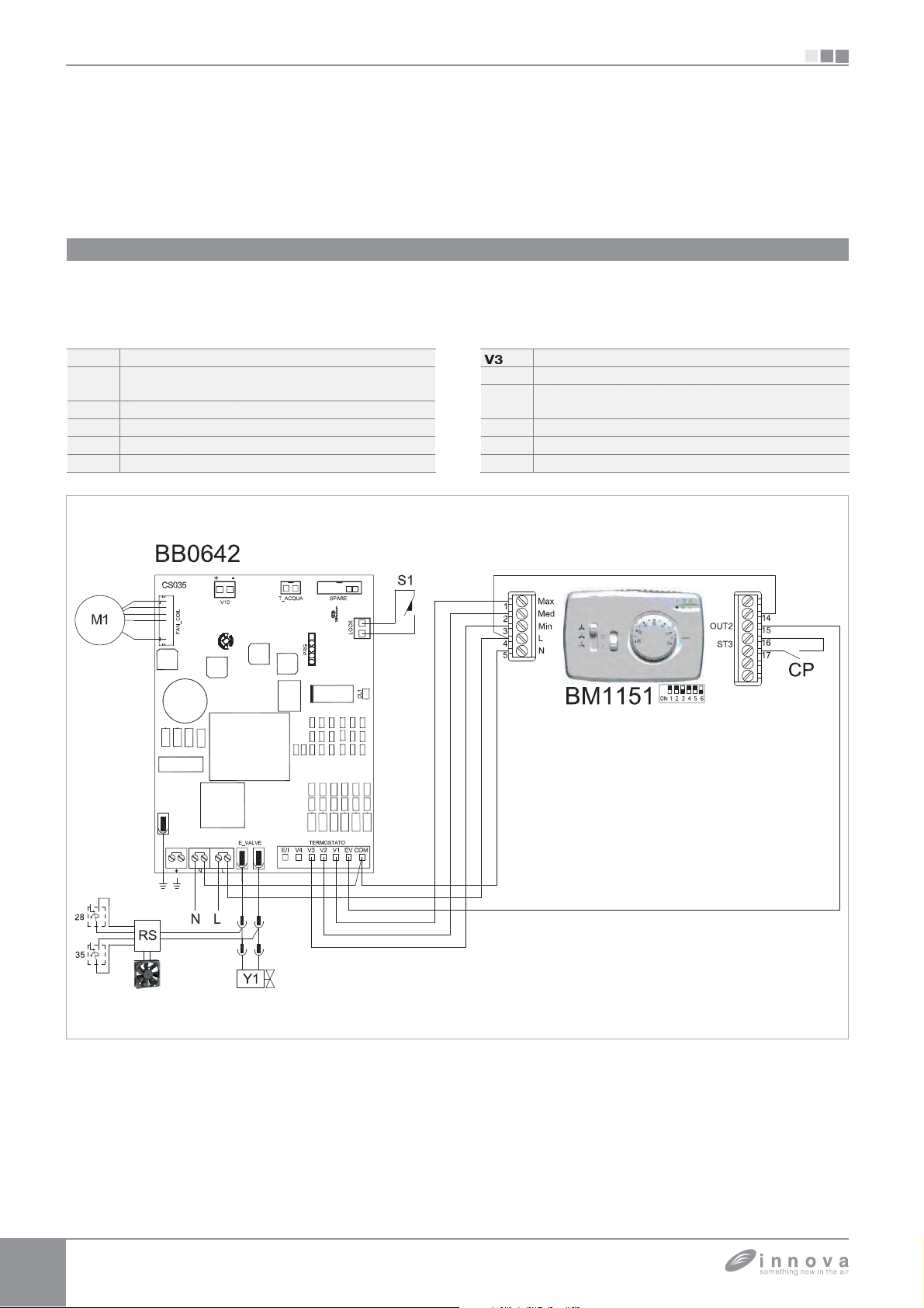
6.1
BB0642 + BM1151 connections diagram
SI
BB0642 + BM1151
he wall-mounted control BM1151II is an electronic
hermostat with ON/OFF switch, a three-speed switch and a
summer
he remote adjustment control BB0642. It is equipped with
L-
E
winter switch. The control must be combined with
230V-50 Hz electrical su
Presence contact input (if closed, the fan coil
oes into stand-by.
ommon inlet neutral
M
Enable input
Max fan speed (1400rpm
Med fan speed (1100rpm
a live output for powering an electrovalve and a presence
ensor input (if closed, the fan coil goes into stand-by
Min fan speed (680rpm
4
Y
1
upersilent speed (450rpm).
water electrovalve (outlet with a volta
30V/50Hz 1A
s version connection
inverter fan moto
icroswitc
e of
Page 39
SI
1
V2
3
Y1
S
pply
pp y
l
p
p( p)
p( p)
p(p)
pp(p)
)
pp(p)
w
)
r
h
W
)
pp()
T
g
g
.
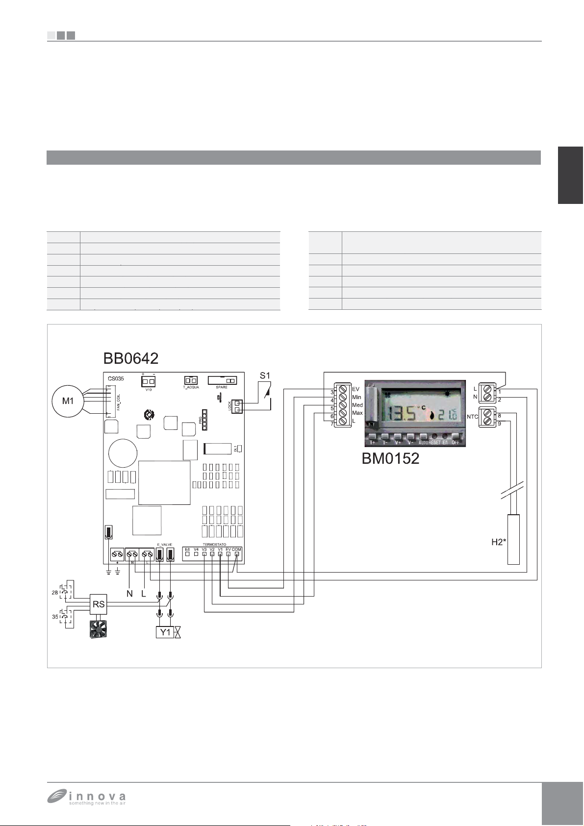
7.1
BB0642 + BM1152 connections diagram
BB0642 + BM1152
BB0642 + BM1152
he built-in control kit BM0152 allows to adjust all the
functions of the fan coil. It is equipped with a live output
for powering an electrovalve. Via the incorporated probe,
it adjusts the room temperature by actin
speeds of the fan coil. If it is connected to the water probe
L-N
V
V
230V-50Hz electrical su
ommon inlet neutra
upersilent speed (450rpm
on the three
located in the device battery well, it controls the minimum
functions durin
functions during the cooling mode (17°C). It must be fitted
in combination with the remote adjustment control BB0642
R
1
the heating mode (42°C) and maximum
ater electrovalve (outlet with a voltage of
230V/50Hz 1A)“
RS version connection
DC inverter fan moto
croswitc
ater temperature probe (2kohm
nto the coil on the unit
EN
Page 40
o
BBBBB
FULL FLAT, RS AND CONNECTION ON THE RIGHT SIDE VERSIONS
f
y
t
r
d
q
p
(
).
g
he device, th
d,
g
g
y
T
g
A
S
T
p
).
FULL FLAT, RS AND CONNECTION ON THE RIGHT SIDE VERSIONS
8.1
Full flat versions connection
o the 230V / 50 Hz power supply for the solenoid valve.
re pre-wired. They can be connected, with the special
connector, to the FF output of the EB0644 and ER0645
control panels. I
an electromechanical thermostat or a non
riginal control are used, connect the two terminals directl
to the control solenoid valve connecto
-to the solenoid valve hea
SI
A
8.2
RS versions connection
In the RS versions, connect the relevant
to the out
board
8.3
ut of electrovalve Y1 provided on the electronic
see Connections paagraph
Water connection on the right side versions motor connection
uick connector
In the event one needs to invert the position of the hydraulic
battery connections from the left side to the ri
t
but since the fan motor and the
constrained in the ori
kit BB0646, available as an accessor
e electric connections box is also inverte
rid safety microswitch are
inal position, one must use the special
.
ht side of
he cable, equipped with male/female connectors, must be
connected on the ri
ht side to the motor and on the left side
B
to the quick connector of the motor present on the board
ref.D).
lso, the two terminals from the grid safety microswitch must
e extended and connected on the left side to contact
resent on the board (ref.E).
he cables are fed through the back of the device through
the s
ecific hole (ref.C
1
NC
NC
PRI
+
MOTOR
4
1
SEC
AUX
+
+
23
12 2112
LN
RSKD
-+
AUX
EV2NEV1N
SW1
1
ON
ZOT
41
211221
RS485
BOILERCHILLER
REMOTE
B
A
BA
AIRH2H4
SW GRL
SW2
4321
CS 35
V1
AN COIL
E VALVE
LN
TACUA
EI
PRG
TERMOSTATO
SPARE
DBtech.c
GDBtech.com
LOCK
DL1
COMEVV1V2V3V4
Page 41

SIU
Page 42

SIU
Page 43

SIU
Page 44

realized with iés technology by
realized with iés technology by
INNOVA s.r. l .
INNOVA s.r. l .
Fraz . Strada, 16 - 38085 PIEVE DI BONO (TN) - ITALY
Fraz . St rada, 16 - 38085 PIEVE DI BONO (TN) - ITALY
tel. +39.0465.670104 fax +39.0465.674965
tel. +39.0465.670104 fax +39.0465.674965
[email protected]
N273539D - Rev. 0
N273541D - Rev. 2
 Loading...