

Page 1

MAXIM Series Controllers
INSTALLATION INSTRUCTIONS
Page 2

Proprietary
No part of this technical manual may be reproduced, transmitted, transcribed, stored in a retrieval
system, or translated into any language or computer language, in any form or by any means, without
prior written permission of Mass Electronics Pty Ltd.
Trademark
The term ‘Innotech’ used in this manual is a trademark of Mass Electronics Pty Ltd trading as
Innotech Control Systems Australia.
'Microso' and 'Windows' are registered trademarks of the Microso Corporation in the United States
and other countries.
Disclaimer
While great eorts have been made to assure the accuracy and clarity of this document, Mass
Electronics Pty Ltd assumes no liability resulting from any omissions in this document, or from
misuse of the information obtained herein. The information in this document has been carefully
checked and is believed to be entirely reliable with all of the necessary information included. Mass
Electronics Pty Ltd reserves the right to make changes to any products described herein to improve
reliability, function and design, and reserves the right to revise this document and make changes
from time to time in content hereof with no obligation to notify any persons of revisions or changes.
Mass Electronics Pty Ltd does not assume any liability arising out of the application or any use of any
product or circuit described herein; neither does it convey licence under its patent rights or the rights
of others.
Page 2 © Mass Electronics Pty Ltd 2011Edition 2.0 dated 20/11/2013
Page 3
Document Management
Document Title:
Maxim Installation Instructions
Revision History
Version
Number
1.0 June 2011
2.0 November 2013 Contact Details Update, Style Update.
Date Summary of Changes
First release of Installation Instructions for Innotech MAXIM Series
Controllers.
Page 3 © Mass Electronics Pty Ltd 2011Edition 2.0 dated 20/11/2013
Page 4

This page has been le intentionally blank.
Page 4 © Mass Electronics Pty Ltd 2011Edition 2.0 dated 20/11/2013
Page 5

Contents
Chapter 1 - Preliminary Information ...............................................................9
1-1 Scope ........................................................................................................................ 10
1-1.1 Systems Covered by this Manual ............................................................................ 10
1-1.2 Terminology used in this manual ...........................................................................11
1-1.3 Document layout ..................................................................................................... 11
1-2 Overview of MAXIM Series Controllers .................................................................... 12
1-2.1 Primary Network Controllers .................................................................................. 12
1-2.2 Sub System Network Controllers ............................................................................13
1-2.3 Sub System Gateway (IG01) ....................................................................................13
1-3 Special Considerations ............................................................................................ 14
1-4 Tools and Materials .................................................................................................. 14
1-2.4 MAXIM I Controller ...................................................................................................14
Chapter 2 - Mechanical Installation ............................................................... 15
2-1 Overview .................................................................................................................. 16
2-2 Physical Description and Dimension Diagrams .....................................................17
2-2.1 Overview ..................................................................................................................17
2-2.2 MAXIM I, II, III, and 1010 Controllers ........................................................................ 17
2-2.3 MiniMAX, MicroMAX, VAVMax, and IG01 ..................................................................18
2-3 General Installation Information ............................................................................20
2-3.1 Overview ..................................................................................................................20
2-3.2 General Installation Guidelines ..............................................................................20
2-3.3 Installing on DIN Rail ...............................................................................................21
Chapter 3 - Electrical Installation .................................................................23
3-1 Overview .................................................................................................................. 24
3-2 Electrical Installation Practices ............................................................................... 24
3-3 MAXIM Controller Wiring .......................................................................................... 24
3-3.1 MAXIM I, II, III, and 1010 Controllers ........................................................................ 26
3-3.2 MiniMAX Controllers (MM01 / MM02) ......................................................................32
3-3.3 VAVMax and MicroMAX Controllers .........................................................................34
3-3.4 IG01 Sub System Gateway .......................................................................................38
Page 5 © Mass Electronics Pty Ltd 2011Edition 2.0 dated 20/11/2013
Page 6

Chapter 4 - Network Installation ..................................................................41
4-1 Overview .................................................................................................................. 42
Chapter 5 - Commissioning ..........................................................................43
5-1 Overview .................................................................................................................. 44
5-2 Inspect the Installation ........................................................................................... 44
Appendix A - Using the CT01 Commissioning Tool ...........................................53
A-1 Overview .................................................................................................................. 54
A-2 Connecting to Subsystem Network Devices ........................................................... 54
A-2.1 Connecting directly to controller on sub system network .................................... 54
A-2.2 Connecting to Sub System Gateway (IG01) ............................................................55
A-2.3 Connecting to sub system network .......................................................................56
A-2.4 CT01 Menus and Navigation ...................................................................................57
A-3 Logging onto the Controller .................................................................................... 57
A-4 VAVMax Settings .......................................................................................................58
A-5 Commissioning ........................................................................................................ 58
A-5.2 Configuring the K-Factor ......................................................................................... 59
A-5.1 Calibration of sensors .............................................................................................59
Customer Assistance ...................................................................................................... 60
Innotech Support ..............................................................................................................60
Page 6 © Mass Electronics Pty Ltd 2011Edition 2.0 dated 20/11/2013
Page 7

List of Illustrations
Figure 2-1:
Figure 2-2:
Figure 2-3:
Figure 2-4:
Figure 2-5:
Figure 2-6:
Figure 2-7:
Figure 3-1:
Figure 3-2:
Figure 3-3:
Figure 3-4:
Figure 3-5:
Figure 3-6:
Figure 3-7:
Figure 3-8:
Figure 3-9:
Figure 4-1:
Typical Enclosure Installation ................................................................................16
MAXIM I and MAXIM II Controller Dimensions ........................................................17
MAXIM III and MAXIM 1010 Controller Dimensions ................................................18
MiniMAX, MicroMAX, VAVMax and IG01 Controller Dimensions.............................19
LCD Optimum Viewing Angle .................................................................................. 20
DIN Rail Dimensions ................................................................................................ 21
Installing MAXIM Controller on a DIN Rail ..............................................................21
MAXIM Series III Connection Details Generated with MAXCon Soware ..............25
MAXIM I controller terminal connection layout .....................................................26
MAXIM II controller terminal connection layout ....................................................26
MAXIM III controller terminal connection layout ...................................................27
MAXIM 1010 controller terminal connection layout ..............................................27
Analogue Output Driving Multiple Solid State Relays ........................................... 30
MiniMAX (MM01 & MM02) Controller Terminal Connection Layout ......................32
VAVMax and MicroMAX Controller Terminal Connection Layout .......................... 34
IG01 Sub System Gateway Terminal Connection Layout ...................................... 38
Innotech Network Diagram ....................................................................................42
Figure 5-1:
Figure 5-2:
Figure 5-3:
Figure 5-4:
Figure 5-5:
Figure 5-6:
Figure A-1:
Figure A-2:
Figure A-3:
Figure A-4:
Checking Power Input Voltage ...............................................................................46
Checking Universal Inputs for 0V ............................................................................47
Checking Digital Relay Output Wiring .................................................................... 48
Checking Analogue Output Voltage .......................................................................50
Checking Analogue Output Resistance ..................................................................51
End of Cable Jumper Locations on Sub Network Devices .................................... 52
Connecting the CT01 to a Sub System Network Device ........................................ 54
Connecting the CT01 to a Sub System Gateway IG01 ...........................................55
Connecting the CT01 to a Sub Network Device .....................................................56
CT01 Interface - Navigation and Menus .................................................................57
Page 7 © Mass Electronics Pty Ltd 2011Edition 2.0 dated 20/11/2013
Page 8

List of Tables
Table 1-1:
Table 1-2:
Table 3-1:
Table 3-2:
Table 3-3:
Table 3-4:
Table 3-5:
Table 3-6:
Table 3-7:
Table 3-8:
Table 3-9:
Table 3-10:
Table 3-11:
Table 3-12:
Table 3-13:
Table 3-14:
Table A-1:
Document Structure ...............................................................................................11
Features of MAXIM Series Controllers ..................................................................... 12
MAXIM I, II, III and 1010 Power Source Specifications ...........................................28
MAXIM I, II, III and 1010 Controller Power Input Terminals ...................................28
Input/Output Range for Universal Inputs ..............................................................29
MAXIM 1010 Universal Outputs ...............................................................................31
MiniMAX Power Source Specifications ...................................................................32
MiniMAX Controller Power Input Terminals ........................................................... 33
MiniMAX Universal Inputs/Outputs ........................................................................ 33
MiniMAX Controllers: Modes of Operation for TRIAC Outputs .............................. 34
VAVMax and MicroMAX Power Source Specifications ............................................ 35
VAVMax and MicroMAX Power Terminals ...............................................................35
VAVMax and MicroMAX Universal Inputs/Outputs .................................................36
VAVMax and MicroMAX Controllers: Modes of Operation for TRIAC Outputs .......37
IG01 Sub System Gateway Power Source Specifications ...................................... 38
IG01 Sub System Gateway Power Terminals .........................................................39
Commissioning Menu .............................................................................................58
Page 8 © Mass Electronics Pty Ltd 2011Edition 2.0 dated 20/11/2013
Page 9

MAXIM Series Controllers
INSTALLATION INSTRUCTIONS
Chapter 1 - Preliminary
Information
Page 10
MAXIM Installation Instructions
1-1 Scope
This manual is intended to provide qualified technical personnel with complete and easy-to-follow
instructions for installing, testing, and commissioning the MAXIM Series Controllers. Although every
eort has been made to simplify the installation process, it is assumed that qualified personnel
installing the MAXIM Series Controllers are familiar with local regulations, codes, and safety
requirements.
It is highly recommended that installers familiarise themselves with the content of this manual
before attempting to install the MAXIM Series Controllers.
Throughout this manual there are icons used to illustrate important information and points of
caution, as illustrated and described below:
NOTE
Notes indicate useful information which should be read.
CAUTION
Cautions indicate critical information which must be read.
1-1.1 Systems Covered by this Manual
A system is defined as one or more MAXIM Series controllers interconnected with various ancillary
units for the purpose of performing specific functions. Systems are intended for use in a variety of
applications and are designed on a modular basis. Modularity provides the most economical and
eicient means of adapting the system to the specific customer requirements. In our attempts to
continuously improve overall customer satisfaction through product improvement, Innotech oen
provides updates and revisions to the MAXIM Series product line. The range of modules result in a
large array of dierent types of hardware available to the customer.
With the exception of the MAXIM 1 controller, all MAXIM Series controllers can either be used in
standalone applications to control external equipment, or in an Innotech network consisting of
multiple controllers and devices supporting Global and Net Comms traic. This manual covers the
following Maxim Series Controllers:
• MAXIM I
• MAXIM II
• MAXIM III
• MAXIM 1010
• MiniMAX (MM01)
• MiniMAX (MM02)
• MicroMAX (UM01)
• VAVMax (VM01)
• Sub System Gateway (IG01)
Page 10 © Mass Electronics Pty Ltd 2011Edition 2.0 dated 20/11/2013
Page 11

MAXIM Installation Instructions
1-1.2 Terminology used in this manual
In order to simplify the instructions, common terminology and references to other Innotech products
are used throughout this manual. A brief description of some of the terminology is provided in this
section.
Net comms communication is the primary means of communication between Innotech hardware and
iComm soware.
Global comms communication is a means of sharing data among dierent Innotech controllers and
devices to carry out dierent functions.
Human Machine Interface (HMI) provides direct access for complete control and operation of various
Innotech controllers. The HMI basically consists of the Liquid Crystal Display (LCD) and the keypad for
direct interaction with the controllers.
1-1.3 Document layout
This technical manual consists of the following sections with a brief description of each section:
Table 1-1: Document Structure
Chapter Description
Chapter 1 - Preliminary
Information
Chapter 2 - Mechanical
Installation
Chapter 3 - Electrical
Installation
Chapter 4 - Network
Installation
This chapter contains general information such as general safety
considerations and an overview of the MAXIM Series controllers.
This chapter contains information such as physical descriptions of
the controllers, mounting dimensions, and mechanical installation
guidelines.
This chapter contains electrical wiring information and instructions.
This chapter provides a general network diagram and reference to the
Innotech Device Network Cabling Manual.
This chapter provides instructions for post-installation inspection of
Chapter 5 - Commissioning
the MAXIM System, and initial setup of the various units that comprise
the system.
Appendix A - Using the
CT01 Commissioning Tool
The Appendix provides instructions on using the CT01 for configuring
MAXIM Series controllers.
Page 11
© Mass Electronics Pty Ltd 2011Chapter 1 – Preliminary Information
Page 12
MAXIM Installation Instructions
1-2 Overview of MAXIM Series Controllers
This section of the manual provides general information for the MAXIM Series Controllers. The
subsequent sections include information on controllers that are installed on the primary network,
and those that are installed on the subsystem network. Information is also provided for the
Subsystem Gateway (IG01). The MAXIM Series controllers are ideal for air conditioning and building
automation, but yet flexible and powerful enough to suit a wide range of other applications.
The MAXIM family of controllers has a wide range of products to suit a broad range of customer
requirements and applications, as illustrated in the table below.
Table 1-2: Features of MAXIM Series Controllers
MAXIM Controllers MiniMAX MicroMAX VAVMax IG01
I II III 1010 MM01 MM02 UM01 VM01 IG01
Configurable
Universal
Inputs
Configurable
Universal
Outputs
Configurable
Universal
Inputs /
Outputs
Digital Relay
Outputs
Analogue
Outputs
TRIAC
Outputs
Thermistor
Input
Dierential
Pressure
Sensor
6 6 20 10 — — — — —
— — — 10 — — — — —
— — — — 7 7 2 2 —
6 6 12 — — — — — —
4 4 8 — — — — — —
— — -- — 4 4 4 4 –
— — — — — — 1 1 —
— — — — — — — 1 —
Net Comms RS232
Global
Comms
Sub Net
Comms
Ethernet — — Optional Optional — — — —
—
— — — — —
— — —
— — —
1-2.1 Primary Network Controllers
The controllers that can be installed on the primary network provide communication channels with
Net and Global comms functionality. These controllers can interface with other Innotech network
resources. The MAXIM Series controllers that can be installed on the Innotech primary network are:
• MAXIM II
• MAXIM III
• MAXIM 1010
• MiniMAX (MM01)
Page 12 © Mass Electronics Pty Ltd 2011Edition 2.0 dated 20/11/2013
Page 13

MAXIM Installation Instructions
These controllers can operate in standalone applications, using the respective universal inputs,
universal outputs, analogue outputs, and digital outputs to transmit and receive information and
control external equipment, or as part of a network of Innotech devices that support Net and Global
comms communication.
However the MiniMAX (MM01) when installed in standalone applications does not provide Real Time
Clock (RTC) synchronization functionality.
1-2.2 Sub System Network Controllers
These controllers are primarily designed to be installed on the subsystem network to be managed
by the Sub System Gateway (IG01). The controllers on the subsystem network do not provide Global
comms functionality. The MAXIM Series controllers that can be installed on the Innotech subsystem
network are:
• MiniMAX (MM02)
• MicroMAX (UM01)
• VAVMax (VM01)
It is important to know that the VAVMax (VM01) and the MicroMAX (UM01) can operate in standalone
applications, using the respective inputs and outputs to receive information to control external
equipment, or as part of a primary network supporting Net comms communication. But in
standalone applications or when installed on a primary network, these controllers will not have all
of the respective features available. Features such as data logging, global points, alarms, and Real
Time Clock synchronization are ONLY available when these controllers are installed on a subsystem
network and managed by the Sub System Gateway (IG01).
Please refer to the datasheet of the relevant controller for more detailed information.
1-2.3 Sub System Gateway (IG01)
The Innotech® Sub System Gateway (IG01) is a gateway between the primary and subsystem
networks. It provides the ability to add subsystem networks of Innotech controllers with a single
communications channel for Net and Global comms functionality. The Sub System Gateway manages
the resources for all connected devices, reducing the load on master controllers in a large network
while reducing network traic. It provides the following functionality to all connected devices that
otherwise would not be available:
• Logging
• Battery backed Real Time Clock Synchronization
• Global points
• Alarms
The Innotech suite of soware can communicate with all devices that are connected to the Sub
System Gateway, providing the transfer of all global points between devices on the primary network
and subsystem network.
Please refer to the Sub System Gateway (IG01) Datasheet for more information.
Page 13
© Mass Electronics Pty Ltd 2011Chapter 1 – Preliminary Information
Page 14

MAXIM Installation Instructions
1-2.4 MAXIM I Controller
The MAXIM I Controller is unique in that it only operates in standalone applications, using the built
in universal inputs, analogue outputs, and digital outputs to transmit and receive information and
control external equipment. The MAXIM I controller cannot be installed on a network.
1-3 Special Considerations
The following precautions and installation considerations must be observed to ensure personal
safety and to prevent damage to equipment:
• Local safety regulations, building codes and ordinances must be complied with during
installation. In cases of conflict with procedures in this manual, contact Innotech or an authorised
representative for clarification.
• To prevent damage to equipment, avoid applying electrical power to the equipment prior to
commissioning, unless specifically instructed to do so in this manual.
• Only qualified personnel familiar with local codes and practices should perform the installation.
Wiring should only be performed by personnel with electronics knowledge and wiring installation
practices.
1-4 Tools and Materials
Other than those listed below, no special tools are required to install the MAXIM Series Controllers:
• Digital Multi Meter (DMM)
• Common hand tools
Page 14 © Mass Electronics Pty Ltd 2011Edition 2.0 dated 20/11/2013
Page 15

MAXIM Series Controllers
INSTALLATION INSTRUCTIONS
Chapter 2 - Mechanical
Installation
Page 16
MAXIM Installation Instructions
2-1 Overview
This section of the manual provides information to allow for the mechanical installation of the MAXIM
Series controllers. Physical descriptions and dimension diagrams are provided for all controllers,
followed by general installation instructions that include installing the MAXIM Series controllers on
industry standard DIN rail.
Innotech recognises that the installation examples described in this manual may not suit the
requirements of all customers. However this document should serve as a guide for all installations,
regardless of whether your particular installation is similar to that of provided examples. In all cases,
installation personnel should familiarise themselves with the information contained in this section.
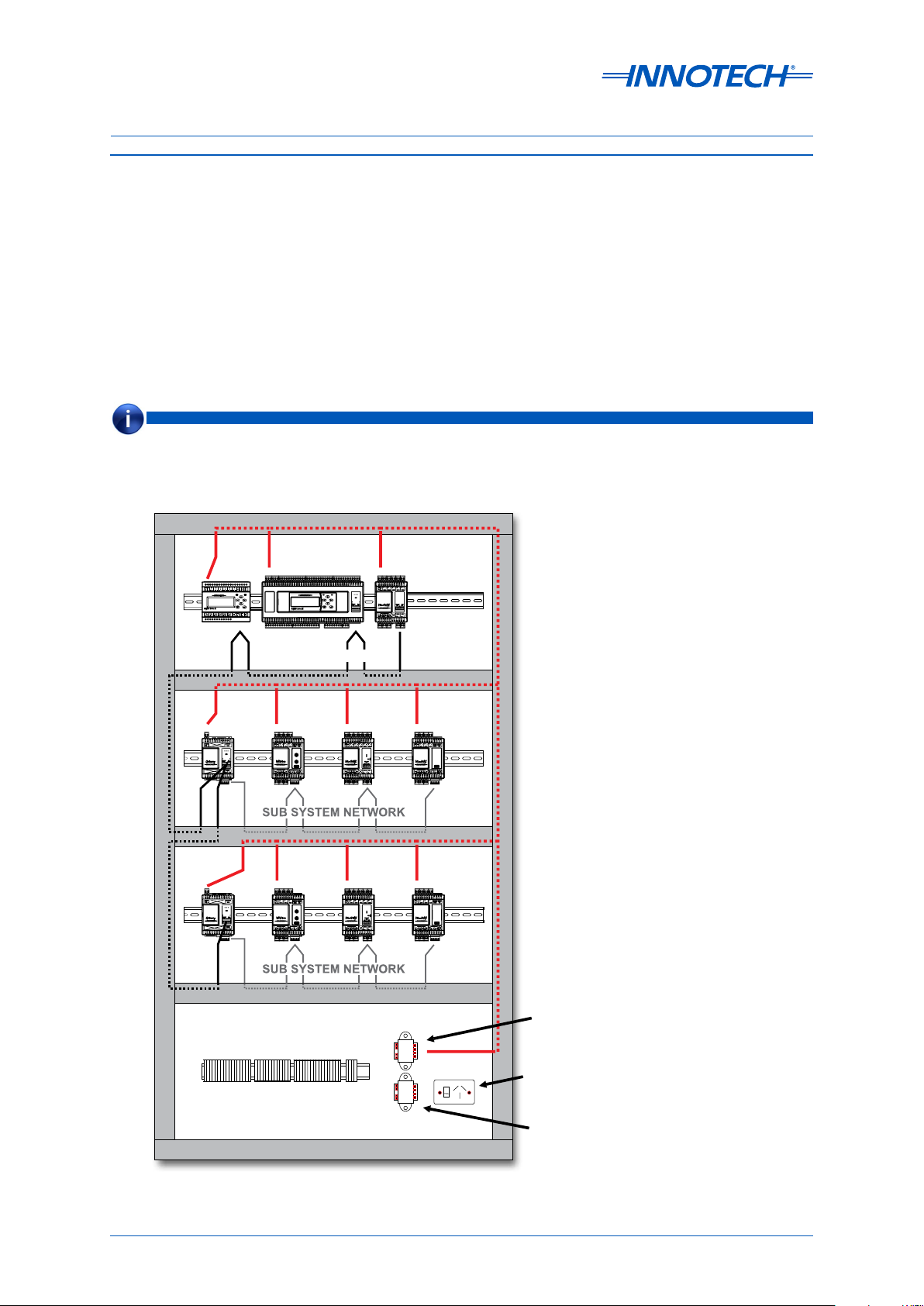
NOTE
It is highly recommended that the MAXIM Series controllers be installed and mounted in a steel enclosure to
minimise the eects of Electro Magnetic Interference (EMI), as illustrated in Figure 2-1 below.
PRIMARY NETWORK
MAXIM II
IG01
IG01
Terminal Strip
MAXIM III
PRIMARY NETWORK
VM01 MM02
VM01
MM02
MM01
UM01
UM01
Digital
Controller
Power
Transformer
General Power
Outlet (GPO)
Auxillary
Power
Transformer
Figure 2-1: Typical Enclosure Installation
Page 16 © Mass Electronics Pty Ltd 2011Edition 2.0 dated 20/11/2013
Page 17
MAXIM Installation Instructions
2-2 Physical Description and Dimension Diagrams
2-2.1 Overview
This section of the manual provides information on the general physical characteristics of the MAXIM
Series controllers, followed by dimension diagrams to help with the mechanical installation.
NOTE
Please note that ALL physical dimensions illustrated in this section are in millimetres.
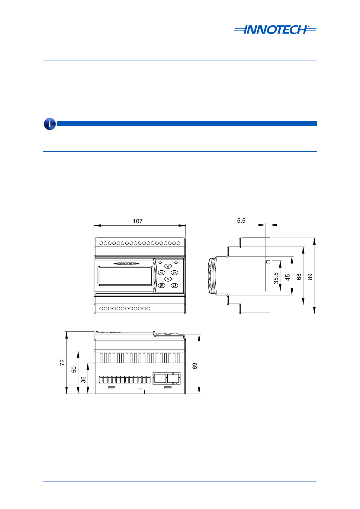
2-2.2 MAXIM I, II, III, and 1010 Controllers
The MAXIM Series I, II, III, and 1010 controllers are housed in DIN cases and are suitable to be mounted
on DIN rail.
The exact dimensions of the MAXIM I and MAXIM II controllers are shown in Figure 2-2 below. Figure
2-3 on the next page shows the dimensions of the MAXIM III and MAXIM 1010 controllers.
Figure 2-2: MAXIM I and MAXIM II Controller Dimensions
Page 17
© Mass Electronics Pty Ltd 2011Chapter 2 – Mechanical Information
Page 18
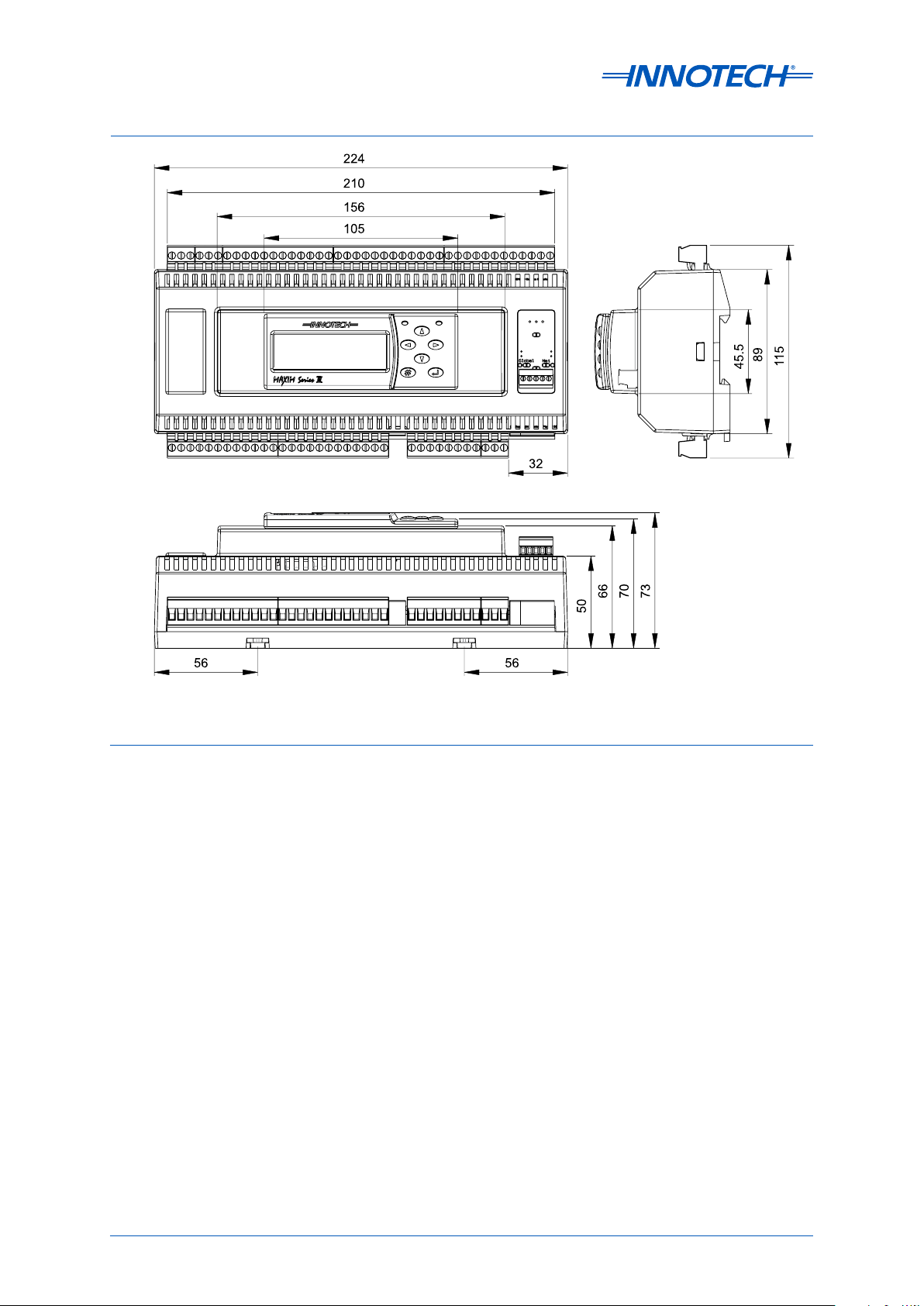
MAXIM Installation Instructions
Figure 2-3: MAXIM III and MAXIM 1010 Controller Dimensions
2-2.3 MiniMAX, MicroMAX, VAVMax, and IG01
These controllers are housed in a compact DIN case and are suitable to be mounted on DIN rail. And
since these controllers are housed in a common case, the dimensions therefore for each controller
are the same, as illustrated in Figure 2-4 on the next page.
Page 18 © Mass Electronics Pty Ltd 2011Edition 2.0 dated 20/11/2013
Page 19

MAXIM Installation Instructions
Figure 2-4: MiniMAX, MicroMAX, VAVMax and IG01 Controller Dimensions
2-2.3.1 VAVMax Dierential Pressure Input
The Dierential Pressure Input is only available on the VAVMax (VM01) controllers. It is used to
measure and respond to changes in air velocity pressure, which is determined by how the VAVMax
controller has been configured. The pressure sensor is factory calibrated for optimum performance
and is an extremely sensitive electromechanical device. Therefore the following guidelines should be
observed to prevent irreparable damage to the pressure sensor:
• Do NOT apply pressure from sources other than a pitot tube
• Do NOT apply excessive static or dierential pressure when connecting or disconnecting air supply
hoses to the VAVMax controller
• Do NOT drop the VAVMax controller
Listed below are the general operational parameters for the Dierential Pressure Input:
• 3000 Pa maximum static operating pressure
• 0 to +250 Pa dierential operating pressure
• -10 to +300 Pa maximum rated dierential pressure
• Accuracy rate of ±5FS
• Only non-corrosive gases are to be used
Page 19
© Mass Electronics Pty Ltd 2011Chapter 2 – Mechanical Information
Page 20

MAXIM Installation Instructions
2-3 General Installation Information
2-3.1 Overview
This section of the manual provides general installation guidelines to assist you with the mechanical
installation of the MAXIM Series controllers.
2-3.2 General Installation Guidelines
The following installation guidelines are provided to ensure continued and reliable operation of the
MAXIM Series controllers:
• The MAXIM I, II, III, and 1010 controllers should be installed in a position that provides easy
access to the optional HMI, and suicient room for power and input/output cabling. Placement
of the these controllers should account for the optimum viewing angle of the LCD, which is
approximately 80° vertically, and 80 ° horizontally, as illustrated in Figure 2-5 below.
• The controllers should not be exposed to high voltage, high current cables, or sources of strong
radio frequency emissions such as transmitter antenna cables.
• The ambient temperature of the MAXIM Series controllers at the installation site should not exceed
the normal operating temperature range recommended for the specific controller.
• The controllers should be installed in an area with minimum vibration and minimum exposure to
mechanical damage.
Figure 2-5: LCD Optimum Viewing Angle
Page 20 © Mass Electronics Pty Ltd 2011Edition 2.0 dated 20/11/2013
Page 21

MAXIM Installation Instructions
2-3.3 Installing on DIN Rail
As mentioned earlier the MAXIM Series controllers are designed to be mounted on DIN rail. The DIN
rail is a set of dierent standardized rails widely used for mounting industrial control equipment
inside equipment racks.
Mounting Slot
18 x 5.2
* All dimensions are in
millimetres.
Figure 2-6: DIN Rail Dimensions
To install a MAXIM Series controller on a DIN rail, align the DIN rail clip on the top edge of the DIN rail.
Push down on the controller until you hear the DIN rail release tab snap onto the bottom edge, as
illustrated in Figure 2-7 below.
To remove the controller, pull the DIN rail release tab down until it releases from the bottom edge of
the DIN rail, and then pull the bottom of the controller away and li up.
Figure 2-7: Installing MAXIM Controller on a DIN Rail
Page 21
© Mass Electronics Pty Ltd 2011Chapter 2 – Mechanical Information
Page 22

MAXIM Installation Instructions
This page has been le intentionally blank.
Page 22 © Mass Electronics Pty Ltd 2011Edition 2.0 dated 20/11/2013
Page 23

MAXIM Series Controllers
INSTALLATION INSTRUCTIONS
Chapter 3 - Electrical
Installation
Page 24

MAXIM Installation Instructions
3-1 Overview
This section of the manual provides information to assist in the electrical installation of the
MAXIM Series controllers, which can be installed in a wide variety of configurations to suit your
requirements.
Innotech recognises that the installation examples described in this manual may not suit the
requirements of all customers. However this document should serve as a guide for all installations,
regardless of whether your particular installation is similar to that of provided examples. In all cases,
installation personnel should familiarise themselves with the information contained in this section.
3-2 Electrical Installation Practices
Devices and equipment should be connected and wired according to their respective installation
instructions and technical documentation.
CAUTION
Please ensure that electrical power to the MAXIM Series controllers and all connected devices and equipment is
turned OFF throughout the installation process. Do NOT apply power to the controllers or any equipment until you
are ready for commissioning as per Chapter 5 – Commissioning.
NOTE
Customers are encouraged to contact Innotech Control Systems Australia or your nearest authorised distributor for
any clarification or further information regarding the installation process.
Cabling plays an important role in the installation of MAXIM Series controllers. Therefore shielded
cable for wiring must be used in all cases. It is also critical to avoid running cables in the vicinity
of high voltage power cables that carry switching voltages and high current. This is especially true
when wiring sensor signal cables.
3-3 MAXIM Controller Wiring
Once a configuration has been transferred to the controller, the MAXCon soware can be used to
generate the connection details for all inputs and outputs as per your configuration. The connection
details can be easily printed and will serve as a great reference to assist you in physically wiring your
particular MAXIM Series controller based on your site requirements. The connection details will show
the terminal and polarity for each configured input and output.
Please refer to MAXCon Online Help for further information on how to generate the connection
details.
An example of the connection details generated for a MAXIM Series III controller is illustrated in Figure
3-1 on the next page.
Page 24 © Mass Electronics Pty Ltd 2011Edition 2.0 dated 20/11/2013
Page 25

MAXIM Installation Instructions
Innotech MAXIM Series III Controller (v6.20)
Figure 3-1: MAXIM Series III Connection Details Generated with MAXCon Soware
Page 25
© Mass Electronics Pty Ltd 2011Chapter 3 – Electrical Installation
Page 26

MAXIM Installation Instructions
UNIVERSAL
ANALOGUE
UNIVERSAL
ANALOGUE
(RS485)
AO
Com
-
AO
1
+
AO
2
+
AO
3
+
AO
4
+
+
+ + + + +
- - - - - -
123456
UI UI UI UI UI UI
0V
24V
DO 1
Net
Comm
DO 2 DO 3 DO 4 DO 5 DO 6
Global
Comm
Shield
NO ComNOCom NO ComNOCom NO ComNO Com
+-+
-
3-3.1 MAXIM I, II, III, and 1010 Controllers
This section of the manual provides wiring information for MAXIM Series I, II, III, and 1010 controllers.
Information is provided on wiring a power source, and all associated inputs and outputs.
The general layout of the input and output terminals for each of these controllers is illustrated in
Figure 3-2 through Figure 3-5 below and on the next page.
POWER
INPUTS
DIGITAL RELAY
OUTPUTS
OUTPUTS
RS 232
PORT
Figure 3-2: MAXIM I controller terminal connection layout
POWER
INPUTS
OUTPUTS
Figure 3-3: MAXIM II controller terminal connection layout
DIGITAL RELAY
OUTPUTS
NET & GLOBAL
COMMS
Page 26 © Mass Electronics Pty Ltd 2011Edition 2.0 dated 20/11/2013
Page 27

MAXIM Installation Instructions
(RS485)
PORT
Universal Inputs
Power
POWER UNIVERSAL INPUTS
DIGITAL RELAY
OUTPUTS
Figure 3-4: MAXIM III controller terminal connection layout
ANALOGUE
OUTPUTS
OPTIONAL
ETHERNET
NET & GLOBAL
COMMS
Universal Outputs Global &
Figure 3-5: MAXIM 1010 controller terminal connection layout
Page 27
Net Comms
RS485
Optional
Ethernet
Port
© Mass Electronics Pty Ltd 2011Chapter 3 – Electrical Installation
Page 28

MAXIM Installation Instructions
3-3.1.1 Power Input
The MAXIM I, II, III, and 1010 controllers may by powered by either an AC or a DC power source. The
operating voltage must meet the requirements of Safety Extra Low Voltage (SELV) to EN60730. The
transformer used must be a safety transformer in compliance with EN60742 and be designed for
100% duty. It must also be sized and fused in compliance with local safety regulations. Power input
specifications for these controllers are detailed in Tab le 3-1 below.
Table 3-1: MAXIM I, II, III and 1010 Power Source Specifications
Controller AC Power Source DC Power Source
MAXIM I and II
MAXIM III
MAXIM 1010
24 V AC ±10%, 50/60 Hz,
Nominal Transformer
rating:
24 V AC ±10%, 50/60 Hz,
Nominal Transformer
rating:
24 V AC ±10%, 50/60 Hz,
Nominal Transformer
rating:
5VA
10VA
16VA
24 V DC ±10%
Nominal Transformer
rating:
24 V DC ±10%
Nominal Transformer
rating:
24 V DC ±10%
Nominal Transformer
rating:
5VA
10VA
16VA
A single transformer may be used to supply voltage to more than one controller, but you must ensure
that the planned load is well within the rating of the transformer. The transformer output terminal
designated as AC Neutral must be solidly earthed to the main earth link of the enclosure panel. The
power input terminals are Terminals 1 and 2 and are detailed in Table 3-2 below.
Table 3-2: MAXIM I, II, III and 1010 Controller Power Input Terminals
Ter minal AC Supply DC Supply
1 24VAC 24VDC
2 0VAC (Neutral) 0VDC
Page 28 © Mass Electronics Pty Ltd 2011Edition 2.0 dated 20/11/2013
Page 29

MAXIM Installation Instructions
3-3.1.2 Universal Inputs
The MAXIM I, II, III, and 1010 controllers are equipped with Universal Inputs that can be configured to
suit a wide range of applications as described in Table 3-3 below. Each Universal Input has a signal
terminal (+) and a reference terminal (–).
Table 3-3: Input/Output Range for Universal Inputs
Input Type Input Range Output Range
Analogue 0-10VDC 0-10VDC
Thermistor
High Thermistor 100kΩ – 680kΩ -20°C to 100°C
Low Thermistor 662kΩ – 12kΩ -50°C to 20°C
Lux Sensor 1MΩ – 0Ω 3 to 2500 LUX
Voltage 0 – 10VDC OFF or ON
Digital
Contact Open or Closed OFF or ON
0 – 10V Square Wave
Voltage
Pulse Counter
Contact
20ms Min. ON Time
20ms Min. OFF Time
Open or Closed
20ms Min. ON Time
0 to 25 pulses per second
0 to 25 pulses per second
20ms Min. OFF Time
Voltage
Duty Cycle
Contact
0 – 1 Square Wave
1 – 13Hz
Open or Closed
1 – 13Hz
0 to 100%
0 to 100%
NOTE
Please note that the LUX Sensor input mode is suitable for switching based on ambient light levels, but is NOT
suitable for any operation which requires the accurate measurement or recording of light levels.
Page 29
© Mass Electronics Pty Ltd 2011Chapter 3 – Electrical Installation
Page 30

MAXIM Installation Instructions
TERMINALS
HEATERS
L1 L2
L3
3-3.1.3 Analogue Outputs
The analogue outputs can be configured with MAXCon soware to either heat valve mode or variable
mode to suit your requirements. Each analogue output has a signal terminal (+) and a shared Com
terminal (–). As illustrated in the connection details in Figure 3-1, the + terminal is the active signal,
and the Com terminal is the signal reference of 0 V, which also can be referred to as ground.
It must be noted that on MAXIM Series I and II controllers only AO1 and AO2 can be configured to heat
valve mode. However on MAXIM Series III all 8 Analogue Outputs can be configured to heat valve
mode.
When an analogue output is configured to heat valve mode, the output is a Pulse Width Modulated
(PWM) signal of 0 or 10V DC with a maximum current rating of 5m A. When an analogue output is
configured to variable mode, the output is an analogue voltage signal varying from 0 to 10 VDC with a
maximum current rating of 5 mA.
When an analogue output is configured as a PWM signal in heat valve mode, up to three Solid State
Relays (SSR) connected in series may be used on each analogue output channel, as illustrated in
Figure 3-6 below. The SSRs must be capable of a trigger voltage of 3 to 32 V DC and zero switching.
ANALOGUE
1 2
TO
HEATERS
1 2
TO
HEATERS
TO
1 2
OUTPUT
-
+
Figure 3-6: Analogue Output Driving Multiple Solid State Relays
If up to 6 SSRs are to be wired in series, you can use the Analogue Output as 0 to 10V DC modulating
in conjunction with the Innotech Heat Valve (IHV) module. Please refer to the following datasheets
for more information on IHVs:
• DS3.31 for IHV Heat Valves
• DS3.32 for IHV42 Heat Valves
3+ve
4
3+ve
4
3+ve
4
Page 30 © Mass Electronics Pty Ltd 2011Edition 2.0 dated 20/11/2013
Page 31

MAXIM Installation Instructions
3-3.1.4 Digital Relay Outputs
The digital relay outputs have two terminals assigned to each channel representing the Normally
Open (NO) and Common (COM) contacts of the associated relay. It is good practice to use pilot
relays for the actual switching functions, particularly when it applies to inductive loads such as coils,
solenoids, and motors. This protects the relays of the Digital Output channel, and allows for the pilot
relays to be installed adjacent to the controlling switch gear.
The Digital Relay Outputs are rated at 24VAC / DC, with a maximum current rating of 2 A supplied by a
Class 2 transformer.
3-3.1.5 Universal Outputs
The MAXIM 1010 controller is equipped with 10 Universal Outputs that can be configured with
MAXCon soware to suit a wide range of applications. Each Universal Output has a signal terminal
(+) and a reference terminal (–). The dierent types of outputs that the Universal Outputs can be
configured as, and the respective range for each are shown in Table 3- 4 below.
Table 3-4: MAXIM 1010 Universal Outputs
Output Type Range
Analogue Output 0 - 10 V DC @ 5mA
Heat Valve / PWM Output 0 / 12 V DC @ 45mA
High Current Digital Output 0 / 12 V DC @ 45mA
On MAXIM 1010 controllers, all Universal Outputs can be configured to heat valve mode. When
the Universal Output is configured to Heat Valve mode, the output is a Pulse Width Modulated
(PWM) signal of 0 or 12V DC with a maximum current rating of 45m A. When the Universal Output is
configured as an analogue output in variable mode, the output is an analogue voltage signal varying
from 0 to 10V DC with a maximum current rating of 5 m A.
In Digital Mode the output can drive 12 V DC relays to 0V DC (OFF) or 12V DC (ON) with a maximum
current rating of 45mA.
Page 31
© Mass Electronics Pty Ltd 2011Chapter 3 – Electrical Installation
Page 32

MAXIM Installation Instructions
3-3.2 MiniMAX Controllers (MM01 / MM02)
This section of the manual provides wiring information for the MiniMAX MM01 and MM02 controllers.
Information is provided on wiring a power source and all associated inputs and outputs.
The general layout of the input and output terminals for each of these controllers is illustrated in
Figure 3-7 below.
Figure 3-7: MiniMAX (MM01 & MM02) Controller Terminal Connection Layout
3-3.2.1 Power Input
The MiniMAX controllers are powered by a 24 V AC power source. The operating voltage must meet the
requirements of Safety Extra Low Voltage (SELV) to EN60730. The transformer used must be a Class 2
safety transformer in compliance with EN60742 and be designed for 100% duty. It must also be sized
and fused in compliance with local safety regulations. Power input specifications for the MiniMAX
controllers are detailed in Ta b l e 3 -5 below.
Table 3-5: MiniMAX Power Source Specifications
Power Source Rating
24 V AC ±10%, 50/60 Hz, Nominal Transformer rating with maximum TRIAC load: 35VA
24 V AC ±10%, 50/60 Hz, Nominal Transformer rating with no TRIAC load: 10VA
Page 32 © Mass Electronics Pty Ltd 2011Edition 2.0 dated 20/11/2013
Page 33

MAXIM Installation Instructions
A single transformer may be used to supply voltage to more than one controller, but you must ensure
that the planned load is well within the rating of the transformer. The transformer output terminal
designated as AC Neutral must be solidly earthed to the main earth link of the enclosure panel. The
dedicated power input terminals are Terminals 1 and 2 and are detailed in Table 3 - 6 below.
Table 3-6: MiniMAX Controller Power Input Terminals
Ter minal AC Supply
1 24VAC
2 0VAC (Neutral
3-3.2.2 Universal Inputs / Outputs
The MiniMAX controllers are equipped with seven Universal Inputs/Outputs which can be configured
with MAXCon soware to be used as inputs or outputs. Each Universal Input/Output has a signal
terminal (+) and a reference terminal (–). The types of inputs and outputs that can be configured and
the respective range for each are shown in Table 3-7 below.
Table 3-7: MiniMAX Universal Inputs/Outputs
UIO Type Input Range Output Range
Analogue Input 0 – 10 V DC 0 – 10V DC
Dry Digital Input Open or Closed OFF or ON
Voltage Digital Input 0 – 10 V DC OFF or ON
Thermistor Input 96 k Ω – 677Ω -20 ° C to 100°C
LUX Sensor Input
Dry Pulse Counter Input
Voltage Pulse Counter Input
20 k Ω – 400Ω
3 to 1000 LUX
0 – 10V Square Wave
1 to 13Hz
0 – 10V Square Wave
20ms Min. ON Time
20ms Min. OFF Time
0 to 2500 LUX
0 to 25 pulses per second
±1 pulse accuracy
0 to 25 pulses per second
±1 pulse accuracy
Analogue Output 0 to 100% 0 – 10 V DC
Digital Output OFF or ON 0 or 10 VDC
PWM Output 0 to 100% 0 to 100% Duty Cycle at 13Hz
When a UIO on a MiniMAX controller is configured as a Thermistor input type, it is designed to be used
with Innotech SEN Series Detectors. The sensing range and accuracy for the SEN Series Detectors is
as follows:
• Nominal sensing range: -5° C to 60 °C
• Accuracy +/-3.5%FS (R25 ° C = 10k Ω )
NOTE
It is not recommended to use the Pulse Counter on these controllers for accumulation as these controllers are not
equipped with battery backup or flash RAM. The MAXIM II, MAXIM III, and MAXIM 1010 controllers are better suited
for such situations.
Page 33
© Mass Electronics Pty Ltd 2011Chapter 3 – Electrical Installation
Page 34

MAXIM Installation Instructions
3-3.2.3 TRIAC Outputs
The MiniMAX controllers are equipped with four TRIAC outputs used for switching the 24 VAC power
supply through to the outputs of the controller. There are four 24V terminals for each TRIAC output,
and two 0 V terminals that are shared by the four TRIAC outputs. The TRIAC outputs are rated at
a minimum current of 20m A and maximum current of 250 mA. The TRIAC outputs can operate in
two modes: Pulse Width Modulation (PWM) or Digital (ON/OFF). The output range for both modes of
operation are described in Table 3-8 below.
Table 3-8: MiniMAX Controllers: Modes of Operation for TRIAC Outputs
TRIAC Output Mode Output Range
Digital ON or OFF
PWM Output 0-100% (0-10VDC)
3-3.3 VAVMax and MicroMAX Controllers
This section of the manual provides wiring information for the VAVMax and MicroMAX controllers.
Information is provided on wiring a power source and all associated inputs and outputs.
The general layout of the input and output terminals for each of these controllers is illustrated in
Figure 3-8 below.
Figure 3-8: VAVMax and MicroMAX Controller Terminal Connection Layout
Page 34 © Mass Electronics Pty Ltd 2011Edition 2.0 dated 20/11/2013
Page 35

MAXIM Installation Instructions
3-3.3.1 Power Input
The VAVMax and MicroMAX controllers are powered by a 24 VAC power source. The operating voltage
must meet the requirements of Safety Extra Low Voltage (SELV) to EN60730. The transformer used
must be a Class 2 safety transformer in compliance with EN60742 and be designed for 100% duty. It
must also be sized and fused in compliance with local safety regulations. Power input specifications
for the VAVMax and MicroMAX controllers are detailed in Table 3 - 9 below.
Table 3-9: VAVMax and MicroMAX Power Source Specifications
Power Source
24 V AC ±10%, 50/60 Hz, Nominal Transformer rating with maximum TRIAC load: 35VA
24 V AC ±10%, 50/60 Hz, Nominal Transformer rating with no TRIAC load: 10VA
A single transformer may be used to supply voltage to more than one controller, but you must ensure
that the planned load is well within the rating of the transformer. The transformer output terminal
designated as AC Neutral must be solidly earthed to the main earth link of the enclosure panel. The
dedicated power input terminals are Terminals 1 and 2 and are detailed in Table 3 -1 0 below.
Table 3-10: VAVMax and MicroMAX Power Terminals
Ter minal AC Supply
1 24VAC
2 0VAC (Neutral)
Page 35
© Mass Electronics Pty Ltd 2011Chapter 3 – Electrical Installation
Page 36

MAXIM Installation Instructions
3-3.3.2 Universal Inputs / Outputs
The VAVMax and MicroMAX controllers are equipped with two Universal Inputs/Outputs which can
be configured with MAXCon soware to be used as inputs or outputs. Each Universal Input/Output
has a signal terminal (+) and a reference terminal (–). The types of inputs and outputs that can be
configured and the respective range for each is shown are Ta ble 3-11 below.
Table 3-11: VAVMax and MicroMAX Universal Inputs/Outputs
UIO Type Input Range Output Range
Analogue Input 0 – 10 V DC 0 – 10V DC
Dry Digital Input Open or Closed OFF or ON
Voltage Digital Input 0 – 10 V DC OFF or ON
Thermistor Input 96 k Ω – 677Ω -20 ° C to 100°C
LUX Sensor Input
Dry Pulse Counter Input
Voltage Pulse Counter Input
20 k Ω – 400Ω
3 to 1000 LUX
0 – 10V Square Wave
1 to 13Hz
0 – 10V Square Wave
20ms Min. ON Time
20ms Min. OFF Time
0 to 2500 LUX
0 to 25 pulses per second
±1 pulse accuracy
0 to 25 pulses per second
±1 pulse accuracy
Analogue Output 0 to 100% 0 – 10 V DC
Digital Output OFF or ON 0 or 10 VDC
PWM Output 0 to 100% 0 to 100% Duty Cycle at 13Hz
When a UIO on a VAVMax or a MicroMAX controller is configured as a Thermistor input type, it is
designed to be used with Innotech SEN Series Detectors. The sensing range and accuracy for the SEN
Series Detectors is as follows:
• Nominal sensing range: -5° C to 60 °C
• Accuracy ±3.5%FS (R25 ° C = 10k Ω )
NOTE
It is not recommended to use the Pulse Counter on these controllers for accumulation as these controllers are not
equipped with battery backup or flash RAM. The MAXIM II, MAXIM III, and MAXIM 1010 controllers are better suited
for such situations.
Page 36 © Mass Electronics Pty Ltd 2011Edition 2.0 dated 20/11/2013
Page 37

MAXIM Installation Instructions
3-3.3.3 TRIAC Outputs
The VAVMax and MicroMAX controllers are equipped with four TRIAC outputs used for switching the
24V AC power supply through to the outputs of the controller. There are four 24 V terminals for each
TRIAC output, and two 0V terminals that are shared by the four TRIAC outputs. The TRIAC outputs
are rated at a minimum current of 20mA, and maximum current of 250mA. The TRIAC outputs can
operate in two modes: Pulse Width Modulation (PWM) or Digital (ON/OFF). The output range for both
modes of operation are described in Table 3 -12 below.
Table 3-12: VAVMax and MicroMAX Controllers: Modes of Operation for TRIAC Outputs
TRIAC Output Mode Output Range
Digital ON or OFF
PWM Output 0-100% (0-10VDC)
NOTE
The use of pilot relays is recommended when switching high voltage and inductive loads.
3-3.3.4 Fixed Thermistor Input
The VAVMax and MicroMAX controllers are equipped with a fixed thermistor input labelled TEMP. The
fixed thermistor input has a signal terminal (+) and a reference terminal (–). This input is designed
for use with the Innotech SEN Series Detectors. The sensing range and accuracy for the SEN Series
Detectors is as follows:
• Nominal sensing range -5° C to 60 °C
• Accuracy +/-3.5%FS (R25 ° C = 10k Ω )
Page 37
© Mass Electronics Pty Ltd 2011Chapter 3 – Electrical Installation
Page 38

MAXIM Installation Instructions
POWER
ETHERNET
3-3.4 IG01 Sub System Gateway
This section of the manual provides wiring information for the IG01 Sub System Gateway. Information
is provided on wiring a power source and all associated inputs and outputs.
The general layout of the input and output terminals for each of these controllers is illustrated in
Figure 3-9 below.
SSG
COMMS
(RS485)
NET & GLOBAL
COMMS
(RS485)
Figure 3-9: IG01 Sub System Gateway Terminal Connection Layout
3-3.4.1 Power Input
The IG01 Sub System Gateway may by powered by either an AC or a DC power source. The operating
voltage must meet the requirements of Safety Extra Low Voltage (SELV) to EN60730. The transformer
used must be a safety transformer in compliance with EN60742 and be designed for 100% duty. It
must also be sized and fused in compliance with local safety regulations. Power input specifications
for these controllers are detailed in Table 3 -13 below.
Table 3-13: IG01 Sub System Gateway Power Source Specifications
AC Power Source DC Power Source
24 V AC ±10%, 50/60 Hz,
Nominal Transformer rating 8VA or greater
24 V DC ±10%
Nominal Transformer rating: 8VA or greater
Page 38 © Mass Electronics Pty Ltd 2011Edition 2.0 dated 20/11/2013
Page 39

MAXIM Installation Instructions
A single transformer may be used to supply voltage to more than one controller, but you must ensure
that the planned load is well within the rating of the transformer. The transformer output terminal
designated as AC Neutral must be solidly earthed to the main earth link of the enclosure panel. The
dedicated power input terminals are Terminals 1 and 2 and are detailed in Table 3 -14 below.
Table 3-14: IG01 Sub System Gateway Power Terminals
Ter minal AC Supply DC Supply
1 24VAC 24VDC
2 0VAC (Neutral) 0VDC
Page 39
© Mass Electronics Pty Ltd 2011Chapter 3 – Electrical Installation
Page 40

MAXIM Installation Instructions
This page has been le intentionally blank.
Page 40 © Mass Electronics Pty Ltd 2011Edition 2.0 dated 20/11/2013
Page 41

MAXIM Series Controllers
INSTALLATION INSTRUCTIONS
Chapter 4 - Network
Installation
Page 42

MAXIM Installation Instructions
4-1 Overview
As mentioned in the Preliminary Information chapter, with the exception of the MAXIM I controller, all
other MAXIM Series controllers can be installed on a primary or a sub system network depending on
your specific model.
Installing a MAXIM Series controller on a network provides the ability to share data among all
controllers and devices on that network. Additionally it also provides the ability for the MAXIM Series
controllers to communicate with the Innotech iComm communication soware, adding advanced
Supervisory Control and Data Acquisition (SCADA) functionality.
The MAXIM Series controllers utilise RS485 balanced (dierential) communications when installed
on a network. Factors such as the type of network, cable distance, and single or multiple network
installation factors must be considered when carrying out a network installation.
An optional Ethernet port is also available on the Sub System Gateway (IG01), and MAXIM Series II, III,
and 1010 controllers for TCP/IP connectivity to your Local Area Network (LAN).
The MAXIM Series controllers have the flexibility to be installed in a wide range of applications.
Although it is not possible to cover all installation situations that may be encountered, following
some general guidelines and instructions will help to ensure the optimum installation for your
particular situation. Therefore please refer to the DS 99.04 Installation Manual for Innotech Device
Network Cabling for complete details and information on performing a network installation with
MAXIM Series controllers.
A general network diagram of Innotech hardware is illustrated in Figure 4-1 below.
Figure 4-1: Innotech Network Diagram
Page 42 © Mass Electronics Pty Ltd 2011Edition 2.0 dated 20/11/2013
Page 43

MAXIM Series Controllers
INSTALLATION INSTRUCTIONS
Chapter 5 Commissioning
Page 44

MAXIM Installation Instructions
5-1 Overview
The commissioning process of the MAXIM Series controllers can only be performed once the
mechanical and electrical installation has been completed, and is intended to ready the controllers
for full operation. The subsequent sections provide detailed information and steps for the
commissioning process.
CAUTION
To prevent injury to personnel and damage to equipment, all electrical power must be turned OFF before starting
the commissioning process. This includes power to the MAXIM Series controllers, and power to the input and
output circuits and equipment. When working with live power ensure that all electrical safety standards for work
on live electrical systems meet local regulatory requirements. Do NOT apply power to any controller or circuit until
instructed to do so by the steps in this section.
5-2 Inspect the Installation
This section of the manual provides detailed steps to perform the final inspection of the installation
process. It is highly recommended that you perform a complete inspection of the mechanical and
electrical installation process to ensure proper operation of the MAXIM Series controllers.
NOTE
Customers are encouraged to contact Innotech Control Systems Australia or your nearest authorised distributor for
any clarification or further information regarding the installation process.
5-2.1 Mechanical Inspection
Please check the following items to complete the mechanical inspection of the installation process:
• Debris such as dust, metal chips, and moisture may have accumulated on the controllers
during the installation process. Please ensure that all controllers are free of any such debris by
thoroughly cleaning as necessary.
• Verify that all controllers are properly installed on DIN rail.
• Verify that cables entering and leaving the cable ducts do not make overly tight bends.
• Verify there is safe access to all MAXIM Series controllers for operation and maintenance.
• Verify that all controllers are installed in a location that is NOT subject to temperature extremes
beyond the normal operating temperature.
• Verify that all controllers are located clear of high current or high voltage cables, and away from
sources that may cause electrical interference.
Page 44 © Mass Electronics Pty Ltd 2011Edition 2.0 dated 20/11/2013
Page 45

MAXIM Installation Instructions
5-2.2 Electrical Inspection
The electrical inspection of the installation process involves verifying all electrical connections
are completed properly, and that there are no external voltages present on any of the inputs and
outputs. The subsequent sections provide detailed information to perform a thorough electrical
inspection of all wiring connections completed during the electrical installation process.
Before proceeding further with the electrical inspection, please check and verify the following items:
• Verify that all electrical power, including power to ancillary equipment is turned OFF.
• Verify all connections have been completed correctly with reference to the connection details
generated for your particular installation.
• Verify that all steel enclosures are properly earthed.
• Verify that all wiring is routed clear of high current or high voltage cables, and away from sources
that may cause electrical interference.
• Verify that all cables and wiring are free from physical damage.
NOTE
Please ensure that the electrical installation process is completed in accordance with DS99.04 Innotech Cabling
Manual. Refer to the Cabling Manual for more detailed information.
Page 45
© Mass Electronics Pty Ltd 2011Chapter 5 – Commissioning
Page 46

MAXIM Installation Instructions
5-2.2.1 Checking Power Inputs
The power inputs must be inspected to ensure that the supplied voltage is within the specifications
of the particular controller, as illustrated in Figure 5-1 below. In cases where a DC power source is
utilised, correct polarity must be verified, and the 0 V terminal must be connected to ground. When
an AC power source is utilised you must verify that the AC Neutral wire is properly earthed and
connected to the 0 V terminal on the particular controller.
You can check and verify correct operation of the 24 VAC and 24V DC power supply inputs by
following the steps below:
1. Verify that the main power and the circuit breaker are both OFF.
2. Verify that the resistance between the main earth link of the enclosure and Terminal 2 of the
controller measures 3Ω or less.
3. Connect the red (+) test lead of your Digital Multi Meter (DMM) to the line voltage side (24V from
the transformer) of the circuit breaker, and the black (–) lead of the DMM to the 0V terminal of
the transformer.
4. Verify that the DMM is set to the proper range to measure 24V. In most cases the AUTO setting
will suit most measurements.
5. Ensuring that the circuit breaker remains OFF, now only turn the 240V supply power ON and
observe the reading on the DMM. The measured voltage should be 24V within ±10%. Please
note that the DMM must be set correctly to measure either AC or DC voltage depending on the
type of power source connected to the controller.
6. You can now turn the 240V supply power OFF and disconnect the DMM.
7. The above steps can be repeated to check the power inputs on other controllers.
24V
TRANSFORMER
From 240V
suply
24V
0V
EARTH
Figure 5-1: Checking Power Input Voltage
Circuit Breaker
OFF
1
2
DIGITAL CONTROLLER
24V
DMM
Page 46 © Mass Electronics Pty Ltd 2011Edition 2.0 dated 20/11/2013
Page 47

MAXIM Installation Instructions
5-2.2.2 Checking Universal Inputs
Before any Universal Inputs are connected to a MAXIM Series controller, you MUST follow the steps
listed below to verify that 0V A C is measured across these inputs. Please note that the voltage will be
measured directly at the Universal Input wiring, and NOT at the controller, as illustrated in Figure 5-2
below. These steps do not apply if a DC source is connected to the Universal Inputs. In this case the
expected voltage to be measured would be that of the source voltage.
Please note that these instructions are also applicable in situations where a Universal Input / Output
on a MAXIM Series controller is configured as a Universal Input. The Universal Input / Output can be
commissioned according to whether it is configured as a Universal Input or a Universal Output.
1. Verify that ALL Universal Inputs are labelled and disconnected from the controller.
2. Verify that the power to the controller is turned OFF.
3. Verify that the power to the equipment to which the Universal Inputs are connected is turned
OFF.
4. Set the DMM voltage range to measure at least 25V AC; the AUTO setting will suit most
measurements.
5. Connect the red (+) lead of the DMM to the Universal Input wire labelled (+), and the black (–)
lead of the DMM to EARTH, as illustrated in Figure 5-2 below.
6. Observe and verify that the DMM measures 0 V AC across the Universal Input wiring. If the
reading is not 0V AC, this could possibly mean that the wiring is incorrect, or the Universal Input
source may not be turned OFF.
Once you have performed these steps and verified 0 V is measured across each Universal Input
wiring, reconnect the wiring one by one to the corresponding Universal Input terminal on the MAXIM
controller. It is important to observe the polarity when reconnecting the wiring to the controller.
CHECKING UNIVERSAL
INPUT SOURCE VOLTAGE
V
V
0V
AC
DC
Connected to equipment
or device
+
Disconnected from
MAXIM controller
EARTH
Figure 5-2: Checking Universal Inputs for 0V
Page 47
© Mass Electronics Pty Ltd 2011Chapter 5 – Commissioning
Page 48

MAXIM Installation Instructions
5-2.2.3 Checking Digital Relay Outputs
The Digital Relay Outputs on MAXIM Series controllers are interfaced through relays, each with Single
Pole Single Throw (SPST) contacts.
Before checking the Digital Relay Outputs, it is important to verify that there are no short circuits
in the external wiring, which can cause the contact current to exceed the maximum rating. Excess
current through the relay contacts can result in permanent damage to the controller.
The following is the general description of the process for safely checking the Digital Relay Outputs,
with detailed steps outlined on the next page. With power applied to the digital output circuits, but
NOT to the MAXIM controller, the output circuits are checked for correct operation. Visually check to
verify that devices connected between the NO and Com terminals are OFF. If the operational status
of these devices cannot be determined by simple observation (indicator lamp ON/OFF, etc.), a DMM
can be used to measure the voltage across the particular device to determine whether or not it is
energised.
The next step is to verify that the output circuits are energised when the Digital Relay Output is
closed. For circuits using the NO contacts, a jumper wire is temporarily connected between the NO
and Com terminals and the associated device is checked to verify that it is energised.
RELAY
ON
24V
AC
V
24V
DC
V
-
+
External
Relays
24V
0V
RELAY
OFF
0V
0V
AC
V
DC
V
-
+
Figure 5-3: Checking Digital Relay Output Wiring
MAXIM
CONTROLLER
TERMINALS
Page 48 © Mass Electronics Pty Ltd 2011Edition 2.0 dated 20/11/2013
Page 49

MAXIM Installation Instructions
The steps below provide further details to check and verify proper operation of the Digital Relay
Outputs on MAXIM Series controllers, as illustrated in Figure 5-3 on the previous page.
1. Verify that the MAXIM controller on which the Digital Relay Outputs will be checked is powered
OFF. You must also verify that power is turned OFF to all of the digital output circuits to be
checked.
2. Beginning at the first device connected to the NO contacts, turn the power ON to the output
device.
3. Visually check to verify that devices connected between the NO and Com terminals are OFF.
If this cannot be verified by a simple visual observation, connect a DMM across the device to
measure the voltage. With the DMM set to the appropriate voltage, verify the that the measured
voltage reads 0V.
4. Verify that the device is OFF by either visual inspection of the device itself, or verifying that the
measured reading on the DMM is 0V.
5. Temporarily connect a jumper wire between the NO and Com contacts of the Digital Relay
Output to be checked. Verify that the jumper wire is of adequate size to temporarily carry the
load.
6. Now turn the power ON to the output device.
7. Verify that the device is ON by either visual inspection of the device itself, or verifying that the
measured reading on the DMM is the expected operating voltage of the device.
8. Turn the power to the output device OFF.
9. Remove the jumper wire connected in Step 6.
10. Repeat Step 2 through Step 10 for the remaining output devices connected to the NO contacts.
Page 49
© Mass Electronics Pty Ltd 2011Chapter 5 – Commissioning
Page 50

MAXIM Installation Instructions
5-2.2.4 Checking Analogue Outputs
The Analogue Output wiring on MAXIM Series controllers should be checked to verify that the output
terminals are free of any external voltage, to verify continuity through the external analogue circuit,
and to verify that the resistance of the external analogue voltage is suicient to avoid overloading the
analogue output circuit.
This procedure is applicable to controllers with dedicated Analogue Outputs, and also applicable to
those controllers equipped with Universal Outputs that have been configured to operate as Analogue
Outputs.
1. Verify that power to the MAXIM controller is turned OFF.
2. Turn the power ON for the Digital Inputs, Digital Outputs, and if applicable the Analogue Inputs.
This step is necessary to detect the presence of voltages at the analogue output terminals that
may be caused by “sneak” circuits or incorrect wiring.
3. Disconnect the active signal wire (+) from the first Analogue Output terminal.
4. Connect the red (+) lead of the DMM to the disconnected active signal wire labelled (+), and the
black (–) lead of the DMM to the Com terminal of the Analogue Output on the controller.
5. The DMM should measure 0V, as illustrated in Figure 5-4 below. Be sure to set the DMM
measurement range to measure the lowest possible voltage to ensure no voltage is present.
6. Change the DMM to measure resistance ( Ω). The DMM should measure a minimum resistance
of 2,000 Ω , as illustrated in Figure 5-5 on the next page. Depending on the DMM, a very high
reading in Mega Ω will indicate an open circuit condition that should be corrected.
7. Disconnect the DMM and reconnect the signal wire(+) that was disconnected in Step 3.
8. Repeat Step 3 through Step 7 for the remaining Analogue Outputs.
9. Turn the power OFF that was applied in Step 2.
CHECKING ANALOGUE
OUTPUT VOLTAGE
Connected to equipment
or device
0V
AC
V
DC
V
+
Figure 5-4: Checking Analogue Output Voltage
EARTH
Page 50 © Mass Electronics Pty Ltd 2011Edition 2.0 dated 20/11/2013
Page 51

MAXIM Installation Instructions
Connected to equipment
or device
2000
AC
V
DC
V
+
CHECKING ANALOGUE
OUTPUT RESISTANCE
Figure 5-5: Checking Analogue Output Resistance
5-2.2.5 TRIAC Outputs
The following items should be checked and verified for proper operation of the TRIAC Outputs on
applicable controllers:
• Verify correct polarity of the wiring connected to the TRIAC outputs.
• Inspect the controlling device for any defects or problems.
• Verify that the current draw for any contactors are within the tolerance of the TRIAC outputs.
• Power ON the TRIAC output (force ON using MAXMon).
• Check the TRIAC output voltages and verify proper operation of the controlling device
CAUTION
A TRIAC output cannot be tested without a load applied. Therefore a load of a minimum current rating of 20mA
must be applied for correct operation of the TRIAC outputs.
Page 51
© Mass Electronics Pty Ltd 2011Chapter 5 – Commissioning
Page 52

MAXIM Installation Instructions
5-2.2.6 End-of-Line Jumpers
The End-of-Line (EOL) jumpers are required for MAXIM Series controllers that are installed on a
subsystem network. There are certain rules that must be followed for proper installation of End-ofLine jumpers.
If only one cable is connected into an RS485 Comms connector on a MAXIM controller installed on a
subsystem network, you must place the EOL jumper on that controller.
If two cables are connected to the same RS485 Comms connector, the jumper should NOT be
installed.
All controllers along the RS485 Comms on a sub system network should be carefully checked to verify
that the EOL jumpers are installed only on the last controller in the network.
NOTE
Refer to DS 99.04 Innotech Cabling Manual for EOLs and comms wiring when using repeaters, or more complex
wiring configurations.
Jumper Setting
Indicator
EOL Termination
Jumper
EOL Termination
Jumper
Jumper Setting
Indicator
EOL Termination
Jumper
Figure 5-6: End of Cable Jumper Locations on Sub Network Devices
Page 52 © Mass Electronics Pty Ltd 2011Edition 2.0 dated 20/11/2013
Page 53

MAXIM Series Controllers
INSTALLATION INSTRUCTIONS
Appendix A - Using the
CT01 Commissioning Tool
Page 54

MAXIM Installation Instructions
A-1 Overview
The Commissioning Tool – Subsystem Network (CT01) is a Human Machine Interface (HMI) that
allows you to configure controllers on a Subsystem network. It provides full access and navigation
through the menu structure of the Subsystem controllers. You can use the CT01 to commission
the controllers as an alternative to the soware method. The CT01 can interface directly with the
following controllers:
• VAVMax (VM01)
• MiniMAX (MM02)
• MicroMAX (UM01)
It can also interface directly with the Subsystem Network using the provided adapter cable. Once
connected to a Subsystem network, the CT01 can be used to search, log onto, and access any
particular controller on that network.
The steps involved in commissioning your controllers using the CT01 are listed below:
• Connecting to the Sub System Network device.
• Logging onto the controller
• Configuring settings on a controller
• Commissioning the controller (Checking Max/Min airflows, Heater Bank testing & Temperature
Calibration)
A-2 Connecting to Subsystem Network Devices
There are three options when connecting the CT01 to the Sub System network, and each is described
and illustrated in the following sections.
A-2.1 Connecting directly to controller on sub system network
If you connect the CT01 directly to a controller on the sub system network, such as a VAVMax, you will
only be able to communicate to that particular controller. You will not be able to connect to other
controllers on the same network, as illustrated in Figure A-1.
Figure A-1: Connecting the CT01 to a Sub System Network Device
Page 54 © Mass Electronics Pty Ltd 2011Edition 2.0 dated 20/11/2013
Page 55

MAXIM Installation Instructions
A-2.2 Connecting to Sub System Gateway (IG01)
When you connect the CT01 to the Innotech Sub System Gateway (IG01) using the provided adaptor
cable, the CT01 can communicate with all subsystem controllers on that network that are connected
to the IG01, as illustrated in Figure A-2 below.
Figure A-2: Connecting the CT01 to a Sub System Gateway IG01
NOTE
The subsystem network must be reconnected as it was before once the commissioning process is complete.
Page 55
© Mass Electronics Pty Ltd 2011Appendix A – Using the CT01 Commissioning Tool
Page 56

MAXIM Installation Instructions
A-2.3 Connecting to sub system network
When you connect the CT01 to the subsystem network at any point using the provided adaptor cable,
the CT01 can communicate with all controllers on the sub system network that are connected to the
IG01, EXCEPT for the controller that is directly connected to the CT01.
The IG01 will need to be unplugged from the subsystem network to allow this type of connection to
work, as illustrated in Figure A-3 below.
Figure A-3: Connecting the CT01 to a Sub Network Device
NOTE
The IG01 must be reconnected as it was before once the commissioning process is complete.
Page 56 © Mass Electronics Pty Ltd 2011Edition 2.0 dated 20/11/2013
Page 57

MAXIM Installation Instructions
A-2.4 CT01 Menus and Navigation
The interface of the CT01 is relatively easy to navigate. To access the Menu page press the Exit
button. To select how the CT01 is connected to the controller, select Setup and press the Enter
button. Use the Up and Down navigation buttons to select between Network or Standalone. If the
CT01 is connected directly to a controller as illustrated in Figure A-1 preivously, you will need to select
Standalone. If the CT01 is connected to the network as illustrated in Figure A-2 and Figure A-3, you
will need to select Network.
Navigation Buttons
Communication LEDs
Log On Button
Enter Button
Exit Button
Figure A-4: CT01 Interface - Navigation and Menus
A-3 Logging onto the Controller
Connect the CT01 to the desired controller, or to the sub system network as described earlier, and the
screen should activate.
Press the Log On button.
Select the controller to communicate with and press the Enter button. If you are connected to a sub
system network, you will have a list of controllers on that network to choose from.
To navigate to the Watch Menu, select Status and press the Enter button. Now select Watches and
press the Enter button. You can now use the Up and Down navigation buttons to scroll through the
available selections. When indicated at the top of the LCD, you can press the Enter button to edit the
applicable set points. Pressing the Exit button will take you back to the previous menu or page. You
can view the following parameters in the Watch Menu:
• Zone temperature and temperature set point
• Cooling and heating demand
• Heater bank request
• Minimum and maximum air flow
• Airflow(L/S), air volume(m/3) and actual airflow set point
• Actuator travel time (only on DODC motors)
• Actuator demand
• Manual VAV calibration (for calibrating the pressure sensor and actuator position)
• Velocity Pressure (Pa)
• Pressure sensor fault status
• Commission mode enable, actuator manual enable, and actuator manual position.
Page 57
© Mass Electronics Pty Ltd 2011Appendix A – Using the CT01 Commissioning Tool
Page 58

MAXIM Installation Instructions
A-4 VAVMax Settings
Configuring a VAVMax controller requires a number of parameters that have to be calibrated. You can
use the CT01 to calibrate the following parameters on a VAVMax controller to suit your requirements:
• Zone temperature set point.
• Minimum Flow rate (L/s) – The minimum design air flow for that particular VAVMax controller.
• Maximum Flow rate (L/s) – The maximum design air flow for that particular VAVMax controller.
• K factor – The K factor is a value of calibration so the VAV Max can translate a pressure dierential
at the VAV into an air volume passing through the VAV.
• Calibration of temperature sensor(s).
A-5 Commissioning
The Commissioning Mode on the CT01 is used for heater bank testing and driving the VAVMax
controller to a manual position for a time period of 4 hours. The Commissioning Mode can be
enabled by following the instructions below:
1. Log onto a VAVMax controller as per the instructions in the previous section.
2. Select Status and press the Enter button. Now select Watches and press the Enter button.
3. Looking at the top of the LCD for menu names, use the navigation buttons to scroll le to the
Commissioning menu.
The Commissioning menu contains the following information:
Table A-1: Commissioning Menu
Item Description
Commissioning Mode
Enable
Commission mode for
4hrs
Actuator Manual
Enable
Actuator Manual
Position
Toggling this ON will enable the commissioning mode for 4hrs, aer which
it will turn OFF. Toggling it ON again will turn commissioning mode OFF
again.
This is a count down timer that will indicate the time remaining before the
commissioning mode turns OFF.
This is to allow manual operation of the VAV actuator whilst
commissioning mode is ON.
This is the required position when the Actuator Manual Enable is switched
ON.
Page 58 © Mass Electronics Pty Ltd 2011Edition 2.0 dated 20/11/2013
Page 59

MAXIM Installation Instructions
A-5.2 Configuring the K-Factor
The K factor value is required to be calibrated to allow the VAVMax controller to correctly read the
pressure and calculate the airflow. The VAVMax does not need to know the duct size because it
is contained within the K factor. The K factor can be set manually, or the VAVMax can calculate it
automatically by following the steps below:
1. Log onto a VAVMax controller as per the instructions in the previous section.
2. Select Commission and press the Enter button.
3. Select Calibrate and press the enter button.
4. Scroll down to Port 4. The parameters Measured and K factor should be visible on the LCD. The
Measured value is the airflow the VAVMax is currently reading.
5. Press the Enter button to calibrate the Measured value. Using the navigation buttons enter
your total measured air volume in L/S for that particular VAVMax controller, and press the Enter
button.
6. The VAVMax will now be calibrated and the K factor will be calculated.
7. Press the Exit button repeatedly to return to the main menu.
NOTE
The K-Factor may need to be rechecked and calibrated when the airflow is set to VMax.
A-5.1 Calibration of sensors
The calibration of sensors is normally completed by the Innotech commissioning technicians.
However the CT01 can be used to calibrate the sensor if the need arises. Follow the steps below to
calibrate sensors:
1. Log onto a VAVMax controller as per the instructions in the previous section.
2. Select Commission and press the Enter button.
3. Select Calibrate and press the enter button.
4. Each port corresponds to an input on the VAVMax controller. Port 3 is a dedicated temperature
input.
5. To calibrate temperature input, take a note of the sensor reading with a reliable thermometer.
6. Scroll to Port 3 and press the Enter button.
7. Using the navigation buttons enter the correct measured temperature and press the Enter
button.
8. This will calibrate the sensor and provide an oset reading.
9. This same process can be used if Ports 1 or 2 are used for temperature inputs.
10. Press the Exit button repeatedly to return to the main menu..
11. The commissioning process is now complete.
NOTE
It is recommended to access and view the watch pages again to verify the controller is operating correctly. Verify
that the temperatures are correct, and the minimum and maximum air flows have been calibrated.
Page 59
© Mass Electronics Pty Ltd 2011Appendix A – Using the CT01 Commissioning Tool
Page 60

Innotech Support
Innotech provides technical information on the Web to assist you with using its products.
At www.innotech.com.au, you can find technical manuals, user instructions, and data sheets for all our
products.
For direct product support or product information, contact your local distributor, or an Innotech
representative.
You can contact us via email, fax, or postal mail:
Website: www.innotech.com.au
Email: sales@innotech.com.au
Fax: +61 7 3421 9101
Mail: Innotech Control Systems
P.O. Box 292
Sunnybank
QLD 4109
Australia
Page 60 © Mass Electronics Pty Ltd 2011Edition 2.0 dated 20/11/2013
 Loading...