

Page 1
IG04 BACnet Gateway / Vaisala WXT/WMT
INSTALLATION INSTRUCTIONS
Page 2

Proprietary
No part of this technical manual may be reproduced, transmitted, transcribed, stored in a retrieval
system, or translated into any language or computer language, in any form or by any means, without
prior written permission of Mass Electronics Pty Ltd.
Trademark
The term ‘Innotech’ used in this manual is a trademark of Mass Electronics Pty Ltd trading as
Innotech Control Systems Australia.
'Microso' and 'Windows' are registered trademarks of the Microso Corporation in the United States
and other countries.
Disclaimer
While great eorts have been made to assure the accuracy and clarity of this document, Mass
Electronics Pty Ltd assumes no liability resulting from any omissions in this document, or from
misuse of the information obtained herein. The information in this document has been carefully
checked and is believed to be entirely reliable with all of the necessary information included. Mass
Electronics Pty Ltd reserves the right to make changes to any products described herein to improve
reliability, function and design, and reserves the right to revise this document and make changes
from time to time in content hereof with no obligation to notify any persons of revisions or changes.
Mass Electronics Pty Ltd does not assume any liability arising out of the application or any use of any
product or circuit described herein; neither does it convey licence under its patent rights or the rights
of others.
Page 2 © Mass Electronics Pty Ltd 2011Edition 5.0 dated 11/11/2013
Page 3

Contents
Proprietary ........................................................................................................................ 2
Trademark ......................................................................................................................... 2
Disclaimer ......................................................................................................................... 2
Overview ........................................................................................................................... 4
Supported Vaisala device models ....................................................................................4
Connecting the Vaisala device and the IG04 BACNet Gateway ....................................... 4
Wiring using the 8-Pin M12 connector with independent cabling for heating ................. 5
Wiring using the 8-Pin M12 connector with split cabling for heating ...............................6
Vaisala device 8-Pin M12 connector Pin-outs ....................................................................7
Wiring using the screw terminal connector with independent cabling for heating ........8
Wiring using the screw terminal connector with split cabling for heating ....................... 9
Vaisala device screw terminal Pin-outs ............................................................................10
Accessing embedded web server and FusionLIVE ........................................................ 11
Home page of embedded web server ..............................................................................12
Animated graphics on the home page .............................................................................13
Configuring Vaisala device with FusionLIVE .................................................................. 15
Configuring IG04 BACnet Gateway with FusionLIVE ..................................................... 16
System Tab.........................................................................................................................16
BACnet Tab ......................................................................................................................... 17
Clock Tab ............................................................................................................................18
Configuring Sunrise and Sunset .......................................................................................19
Ethernet Tab ......................................................................................................................20
Services Tab ....................................................................................................................... 21
Troubleshooting .............................................................................................................22
Cannot discover a new IG04 BACnet Gateway .................................................................22
Cannot connect to the embedded web server ................................................................22
Cannot launch FusionLIVE ................................................................................................23
Unstable connection with embedded web server or FusionLIVE ...................................23
Customer Assistance ...................................................................................................... 24
Innotech Support ..............................................................................................................24
Page 3 © Mass Electronics Pty Ltd 2011Edition 5.0 dated 11/11/2013
Page 4

Installation Instructions for Innotech IG04 BACnet Gateway and Vaisala Transmitter / Sensor
Overview
This document provides instructions to connect a Vaisala device to the IG04 BACnet Gateway, and
configuring the Vaisala device and IG04 using the embedded web server and the FusionLIVE Java
application.
Detailed instructions are provided to help you access the embedded web server, and easily configure
the IG04 and Vaisala device. It is recommended that installation personnel familiarise themselves
with the information contained in this document.
Supported Vaisala Device Models
The IG04 BACnet Gateway communicates directly with the Vaisala device using a dedicated RS-485
channel. The IG04 BACnet Gateway is designed to communicate with the Vaisala WXT520 Weather
Transmitter or WMT52 Ultrasonic Wind Sensor.
For 'plug and play' communications, ensure to use one of the following order codes when ordering a
Vaisala device:
• WXT520-AACxxxxxx0 (where "x" refers to optional extras)
• WMT52-AACxxxxxx0 (where "x" refers to optional extras)
NOTE
If a dierent order code is required, ensure that the Vaisala device is congured to communicate using the NMEA
protocol on RS-485 at 19200 baud 8, N, 1.
Connecting the Vaisala Device and the IG04 BACnet Gateway
A Vaisala device can be connected to the IG04 BACnet Gateway using either the 8-Pin M12 connector
or by wiring directly to the Screw Terminals. Both the 8-Pin M12 Connector and Screw Terminals can
be accessed from the bottom of the Vaisala device.
The Vaisala device and the IG04 BACnet Gateway can be powered using a 24 V to 32V DC power
supply. If heating is required, it is recommended to provide independent cabling from the power
supply to ensure robust operation and minimal interference. If this is not possible, a single cable run
can be used to provide power for both the Vaisala device and optional heating accessory. Ensure to
use high capacity cable suitable for carrying such a current load over the distance required.
Refer to the following wiring guides for the most suitable option for your installation.
NOTE
Please refer to the appropriate Vaisala technical documentation for more details at www.vaisala.com. Refer to the
relevant datasheets for complete power supply details for the IG04 and Vaisala products.
Page 4 © Mass Electronics Pty Ltd 2011Edition 5.0 dated 11/11/2013
Page 5
Installation Instructions for Innotech IG04 BACnet Gateway and Vaisala Transmitter / Sensor
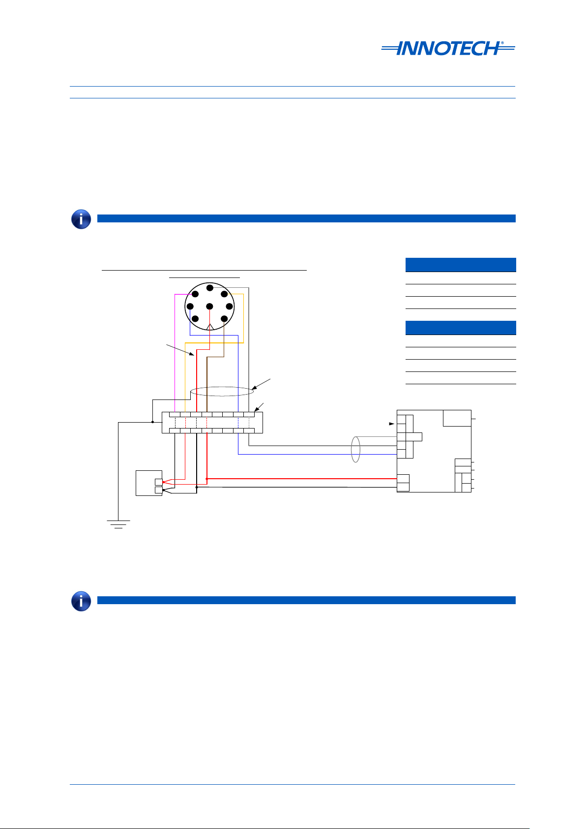
Wiring Using The 8-Pin M12 Connector With Independent Cabling For Heating
The wiring example provided below at Figure 1 is recommended for most installations, providing a
separate cabling run of high quality cable for the Vaisala device heating current (if required). The pin
connections for the 8-Pin M12 and wire colours are listed in Table 1 on page 7.
For installations that do require the optional heating accessory, ensure a high capacity cable
between the DC Power supply and the Vaisala device is used.
NOTE
The 8-Pin M12 connector is located on the bottom of the Vaisala device.
IG04 Default Settings
Vaisala WXT520 Weather Transmitter / WMT52 Ultrasonic Wind Sensor
Note: Colour coded as per
Vaisala documentation
M12 connector pin-out *
5
6
7
8
1 2
YEL (Vh+)
PNK (Vh−)
RED Wire (Vin−)
BRN Wire (Vin+)
1
4
3
Shielded cable length should NOT exceed
BLU Wire (RX−)
3m when connecting WXT520 / WMT52
GRY Wire (RX+)
Device to WSP150 Surge Protector
IG04 Default Settings
IP Address: 192.168.2.100 (Static)
IP Address 192.168.2.100 (Static)
S/M: 255.255.255.0
HTTP Port: 80
Subnet Mask 255.255.255.0
Innotech Port: 20000
BACnet/IP
HTTP Port 80
BACnet Port: 47808
BACnet Instance: 1509
Innotech Port 20000
Baud Rate: 19200
Fault Timeout: 30 Sec
BACnet/IP
BACnet Port 47808
BACnet Instance 1509
Baud Rate 19200
Fault Timeout 30 seconds
If a surge protector is not installed, connect the cables directly
1
*
GRY Wire (RX+)
BLU Wire (RX−)
SER Terminal Not Used
(Service Tool Connection)
*3
Higher heating currents cause
voltage drop. Select cable with sufficient
cross section for longer runs.
SER
+
-
S
SHLD
WXT
+
-
24V
0V
Ethernet
&
BACIP
Innotech IG04
BACnet Gateway
EOL
SHLD
MSTP
C-
C+
Ethernet
Port &
BACnet/
IP Output
RS485 Line
Termination
Jumper
RS485 [
Shield
RS485 [-]
RS485 [+]
]
16mm² Copper Cable
Earth Ground
*1
Isolated DC
Power Supply
+
-
24V to 32V DC
@ < 200mA
@ < 800mA
1 2 3 4 5 6 7 8
WSP150 Surge Protector
1 2 3 4 5 6 7 8
BLK Wire (Vin−)
BLK Wire (Vh−)
RED Wire (Vh+)
RED Wire (Vin+)
2
*
*3
*1
WSP150 Surge Protector in accordance with
appropriate Vaisala technical documentation.
*2
Wire WXT520 / WMT52 Device to the
When heating is NOT used.
Figure 1: Wiring guide for Vaisala device M12 Connector with independent cabling for heating
NOTE
The 16 mm2 Copper Cable to Earth Ground cable is a critical component for the correct operation of the surge protector.
Ensure this is installed correctly.
Page 5 © Mass Electronics Pty Ltd 2011Edition 5.0 dated 11/11/2013
Page 6
Installation Instructions for Innotech IG04 BACnet Gateway and Vaisala Transmitter / Sensor
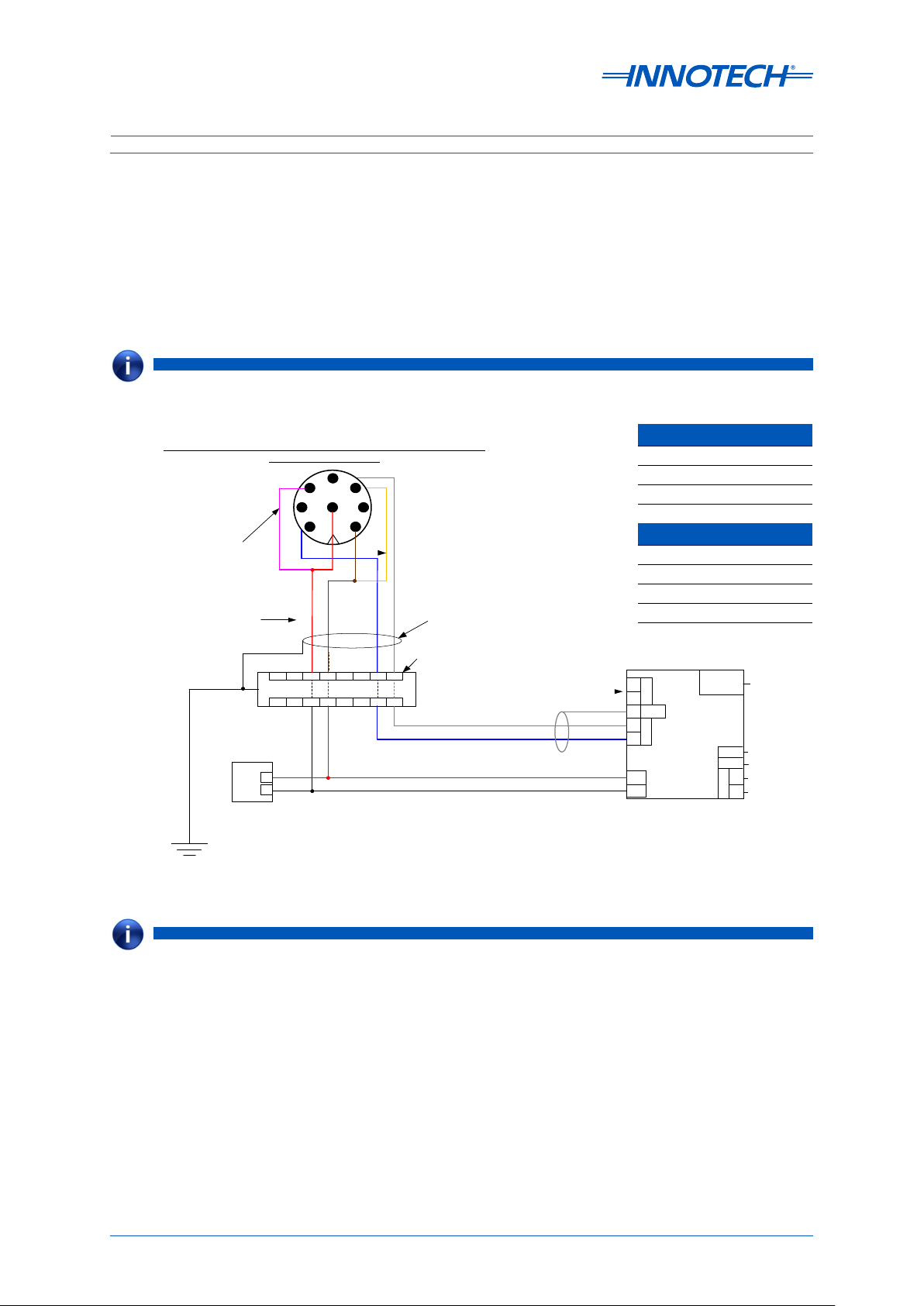
Wiring Using The 8-Pin M12 Connector With Split Cabling For Heating
The wiring example provided below at Figure 2 is an alternative M12 connector wiring guide,
providing a shared cabling run of suitable high capacity cable for the Vaisala device and heating
accessory (if required). The pin connections for the 8-Pin M12 and wire colours are listed in Table 1 on
page 7.
For installations that do require the optional heating accessory, ensure a high capacity cable
between the DC Power supply and the Vaisala device is used.
NOTE
The 8-Pin M12 connector is located on the bottom of the Vaisala device.
IG04 Default Settings
Vaisala WXT520 Weather Transmitter / WMT52 Ultrasonic Wind Sensor
Only used when
heating is required
Note: Colour coded as per
Vaisala documentation
M12 connector pin-out *
6
7
8
1 2
PNK (Vh− )
RED Wire (Vin−)
BRN Wire (Vin+)
1
5
4
3
YEL (Vh+)
Shielded cable length should NOT exceed
BLU Wire (RX−)
3m when connecting WXT520 / WMT52
GRY Wire (RX+)
Device to WSP150 Surge Protector
IG04 Default Settings
IP Address: 192.168.2.100 (Static)
IP Address 192.168.2.100 (Static)
S/M: 255.255.255.0
HTTP Port: 80
Subnet Mask 255.255.255.0
Innotech Port: 20000
BACnet/IP
HTTP Port 80
BACnet Port: 47808
BACnet Instance: 1509
Innotech Port 20000
Baud Rate: 19200
Fault Timeout: 30 Sec
BACnet/IP
BACnet Port 47808
BACnet Instance 1509
Baud Rate 19200
Fault Timeout 30 seconds
If a surge protector is not installed, connect the cables directly
1
*
GRY Wire (RX+)
BLU Wire (RX−)
SER Terminal Not Used
(Service Tool Connection)
3
*
When heating IS used.
If heating is required and supplied via the
same supply wires, ensure a substantial cable
with cross-section > 1mm
excessive voltage drops. Excessive voltage
drops may cause comms problems.
2
is used to avoid
SER
+
-
S
SHLD
WXT
+
-
24V
0V
Ethernet
&
BACIP
Innotech IG04
BACnet Gateway
EOL
SHLD
MSTP
C-
C+
Ethernet
Port &
BACnet/
IP Output
RS485 Line
Termination
Jumper
RS485 [
Shield
RS485 [-]
RS485 [+]
]
16mm² Copper Cable
Earth Ground
*1
Isolated DC
Power Supply
+
-
24V to 32V DC
@ < 200mA
@ < 800mA
1 2 3 4 5 6 7 8
WSP150 Surge Protector
1 2 3 4 5 6 7 8
BLK Wire (Vin−)
RED Wire (Vin+)
*1
*2
*3
Wire WXT520 / WMT52 Device to the
WSP150 Surge Protector in accordance with
appropriate Vaisala technical documentation
*2
When heating is NOT used.
Figure 2: Wiring guide for Vaisala device M12 Connector with split cabling for heating
NOTE
The 16 mm2 Copper Cable to Earth Ground cable is a critical component for the correct operation of the surge protector.
Ensure this is installed correctly.
Page 6 © Mass Electronics Pty Ltd 2011Edition 5.0 dated 11/11/2013
Page 7

Installation Instructions for Innotech IG04 BACnet Gateway and Vaisala Transmitter / Sensor
Vaisala Device 8-Pin M12 Connector Pin-Outs
NOTE NOTE
Please take extreme care to ensure when installing and wiring that the wire colours and terminals correctly match
as illustrated in Figure 1 or Figure 2, and described below in Table 1. Refer to the appropriate Vaisala technical
documentation for more details at www.vaisala.com.
Table 1: M12 Pin-outs for WXT520 / WMT52
Wire Colour M12 Pin# RS-485
Blue 7 RX-
Grey 5 RX+
White 1
Green 3
Pink 6 Vh- (heating GND)
Yellow 4 Vh+ (heating supply voltage)
Red 8 Vin- (operating GND)
Brown 2 Vin+ (operating supply voltage)
NOTE NOTE
Exact minimum cable specications for the power supply will vary, and are installation specic. Ensure to select the
correct cable to carry the current load as required.
Page 7 © Mass Electronics Pty Ltd 2011Edition 5.0 dated 11/11/2013
Page 8
Installation Instructions for Innotech IG04 BACnet Gateway and Vaisala Transmitter / Sensor
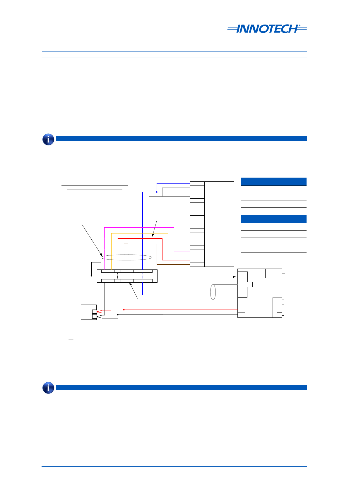
Wiring Using The Screw Terminal Connector With Independent Cabling For Heating
The wiring example provided below at Figure 3 is recommended for most installations, providing a
separate cabling run of high quality cable for the heating current (if required). The pin connections for
the screw terminal connector and wire colours are listed in Table 2 on page 10.
For installations that do require the optional heating accessory, ensure a high capacity cable
between the DC Power supply and the Vaisala device is used.
NOTE
The screw terminal connector can be accessed from the bottom of the Vaisala device by unscrewing the three screws on
the Vaisala device's chassis, and carefully revealing the terminals. Cable runs can be fed through the small pluggable
holes in the base of the unit. Ensure to fully seal the Vaisala device once wiring is complete.
Vaisala WXT520 Weather Transmitter /
WMT52 Ultrasonic Wind Sensor
Screw Terminal connector pin-out *
Shielded cable length should NOT exceed
3m when connecting WXT520 / WMT52
Device to WSP150 Surge Protector
1
*
1 2 3 4 5 6 7 8
WSP150 Surge Protector
1 2 3 4 5 6 7 8
16mm² Copper Cable
Earth Ground
Isolated DC
Power Supply
+
-
24V to 32V DC
@ < 200mA
@ < 800mA
2
*
*3
BLK Wire (Vin−)
RED Wire (Vh+)
BLK Wire (Vh−)
BLU Wire (RX−)
1
PNK (Vh− )
YEL (Vh+)
RED Wire (Vin−)
BRN Wire (Vin+)
1
*
RED Wire (Vin+)
If a surge protector is not installed,
connect the cables directly
*1
Wire WXT520 / WMT52 Device to the
WSP150 Surge Protector in accordance with
appropriate Vaisala technical documentation.
*2
When heating is NOT used.
GRY Wire (RX+)
Note: Colour coded as
per Vaisala
GRY Wire (RX+)
BLU Wire (RX−)
1 RX-
2 RX+
3 TX-
4 TX+
5 RXD
6 SGND
7 EXH
8 EXL
9 SIPB
10 SIPA
WXT520 / WMT52
Screw Terminals
11 SR-
12 SR+
13 PT-
14 PT+
15 AGND
16 AGND
17 HTG-
18 HTG+
19 VIN-
20 VIN+
SER Terminal Not Used
(Service Tool Connection)
*3
Higher heating currents cause
voltage drop. Select cable with sufficient
cross section for longer runs.
IG04 Default Settings
IG04 Default Settings
IP Address: 192.168.2.100
IP Address 192.168.2.100 (Static)
S/M: 255.255.255.0
HTTP Port: 80
Subnet Mask 255.255.255.0
Innotech Port: 20000
BACnet/IP
HTTP Port 80
BACnet Port: 47808
BACnet Instance: 1509
Innotech Port 20000
Baud Rate: 19200
Fault Timeout: 30 Sec
BACnet/IP
BACnet Port 47808
BACnet Instance 1509
Baud Rate 19200
Fault Timeout 30 seconds
SER
+
-
S
SHLD
WXT
+
-
24V
0V
Ethernet
Innotech IG04
BACnet Gateway
BACIP
&
SHLD
EOL
MSTP
C-
C+
Ethernet
Port &
BACnet/
IP Output
RS485 Line
Termination
Jumper
RS485 [
RS485 [-]
RS485 [+]
Shield
]
Figure 3: Wiring guide for Vaisala device screw terminal connector with independent cabling for
heating
NOTE
The 16 mm2 Copper Cable to Earth Ground cable is a critical component for the correct operation of the surge protector.
Ensure this is installed correctly.
Page 8 © Mass Electronics Pty Ltd 2011Edition 5.0 dated 11/11/2013
Page 9

Installation Instructions for Innotech IG04 BACnet Gateway and Vaisala Transmitter / Sensor
Wiring Using The Screw Terminal Connector With Split Cabling For Heating
The wiring example provided below at Figure 4 is an alternative screw terminal wiring guide,
providing a shared cabling run of suitable high capacity cable for the Vaisala device and heating
accessory (if required). The pin connections for the screw terminal connector and wire colours are
listed in Table 2 on page 10.
For installations that do require the optional heating accessory, ensure a high capacity cable
between the DC Power supply and the Vaisala device is used.
NOTE
The screw terminal connector can be accessed from the bottom of the Vaisala device by unscrewing the three screws on
the Vaisala device's chassis, and carefully revealing the terminals. Cable runs can be fed through the small pluggable
holes in the base of the unit. Ensure to fully seal the Vaisala device once wiring is complete.
Vaisala WXT520 Weather Transmitter /
WMT52 Ultrasonic Wind Sensor
Screw Terminal connector pin-out *
Note: Colour coded as per
Vaisala documentation
Shielded cable length should NOT exceed
3m when connecting WXT520 / WMT52
Device to WSP150 Surge Protector
If a surge protector is not installed,
connect the cables directly
1
*
1 2 3 4 5 6 7 8
WSP150 Surge Protector
1 2 3 4 5 6 7 8
Isolated DC
16mm² Copper Cable
Earth Ground
Power Supply
24V to 32V DC
@ < 200mA
@ < 800mA
BLK Wire (Vin−)
+
-
*²
*3
BLU Wire (RX−)
GRY Wire (RX+)
Only used when
heating is required
PNK (Vh− )
YEL (Vh+)
GRY Wire (RX+)
BLU Wire (RX−)
1
RED Wire (Vin−)
BRN Wire (Vin+)
1
*
RED Wire (Vin+)
*1
Wire WXT520 / WMT52 Device to the
WSP150 Surge Protector in accordance with
appropriate Vaisala technical documentation.
*2
When heating is NOT used.
1 RX-
2 RX+
3 TX-
4 TX+
5 RXD
6 SGND
7 EXH
8 EXL
9 SIPB
10 SIPA
WXT520 / WMT52
Screw Terminals
11 SR-
12 SR+
13 PT-
14 PT+
15 AGND
16 AGND
17 HTG-
18 HTG+
19 VIN-
20 VIN+
SER Terminal Not Used
(Service Tool Connection)
3
*
When heating IS used.
If heating is required and supplied via the
same supply wires, ensure a substantial cable
with cross-section > 1mm
excessive voltage drops. Excessive voltage
drops may cause comms problems.
2
is used to avoid
IG04 Default Settings
IP Address 192.168.2.100 (Static)
Subnet Mask 255.255.255.0
HTTP Port 80
Innotech Port 20000
BACnet/IP
BACnet Port 47808
BACnet Instance 1509
Baud Rate 19200
Fault Timeout 30 seconds
+
-
S
+
-
24V
0V
IG04 Default Settings
IP Address: 192.168.2.
S/M: 255.255.255.0
HTTP Port: 80
Innotech Port: 20000
BACnet/IP
BACnet Port: 47808
BACnet Instance: 1509
Baud Rate: 19200
Fault Timeout: 30 Sec
SER
SHLD
WXT
Innotech IG04
BACnet Gateway
Ethernet
&
BACIP
SHLD
EOL
MSTP
C-
C+
Ethernet
Port &
BACnet/
IP Output
RS485 Line
Termination
Jumper
RS485 [
Shield
RS485 [-]
RS485 [+]
]
Figure 4: Wiring guide for Vaisala device screw terminal connector with split cabling for heating
NOTE
The 16 mm2 Copper Cable to Earth Ground cable is a critical component for the correct operation of the surge protector.
Ensure this is installed correctly.
Page 9 © Mass Electronics Pty Ltd 2011Edition 5.0 dated 11/11/2013
Page 10

Installation Instructions for Innotech IG04 BACnet Gateway and Vaisala Transmitter / Sensor
Vaisala Device Screw Terminal Pin-Outs
NOTE NOTE
Please take extreme care to ensure when installing and wiring that the wire colours and terminals correctly match
as illustrated in Figure 1 or Figure 2, and described below in Table 2. Refer to the appropriate Vaisala technical
documentation for more details at www.vaisala.com.
Table 2: Screw Terminal Pin-outs for WXT520 / WMT52
Screw Terminal Pin RS-485
1 RX- RX-
2 RX+ RX+
3 TX- RX-
4 TX+ RX+
5 RXD
6 SGND
7 EXH
8 EXL
9 SIPB
10 SIPA
11 SR-
12 SR+
13 PT-
14 PT+
15 AGND
16 AGND
17 HTG- Vh- (heating GND)
18 HTG+ Vh+ (heating supply voltage)
19 VIN- Vin- (operating GND)
20 VIN+
Vin+ (operating supply
voltage)
NOTE NOTE
Exact minimum cable specications for power supply will vary, and are installation specic. Ensure to select the correct
cable to carry the current load as required.
Page 10 © Mass Electronics Pty Ltd 2011Edition 5.0 dated 11/11/2013
Page 11

Installation Instructions for Innotech IG04 BACnet Gateway and Vaisala Transmitter / Sensor
Accessing Embedded Web Server and FusionLIVE
The Vaisala device and IG04 BACnet Gateway can be configured using the embedded web server
and the FusionLIVE Java application on the IG04. However before you can access the embedded
web server, your computer must be configured to be on the same network range as the IG04 BACnet
Gateway. The default Ethernet settings for the IG04 BACnet Gateway are shown in Table 3 below.
Table 3: IG04 BACnet Gateway Default Ethernet Settings
IP address Gateway Subnet mask Port Number
192.168.2.100 0.0.0.0 255.255.255.0 80
NOTE
Please note that the Java Runtime Environment (JRE) must be installed on your computer in order to access
the embedded web server and the FusionLIVE application. The latest version of JRE can be downloaded from
http://java.com/en/.
Since the default IP address of the IG04 BACnet Gateway is 192.168.2.100, your computer must be
configured with an IP address in the range of 192.168.2.xxx, and the subnet mask must be configured
to 255.255.255.0. When you have configured the IP address and subnet mask of your computer, you
can access the web server using Microso Internet Explorer® Web Browser Version 8 or greater.
Follow the instructions below to connect to the IG04 BACnet Gateway and access the embedded web
server.
Launch Internet Explorer and enter the default IP address of the IG04 BACnet Gateway in the address
bar and press Enter, as illustrated in Figure 5 below.
http://192.168.2.100/
Figure 5: Access embedded web server using default IP address
If you changed the port number in the Ethernet Settings, you must specify the port number with the
IP address when entered into the address bar, as illustrated in Figure 6 below.
http://192.168.2.100:90
Figure 6: Access embedded web server using IP address with a dierent port
NOTE
For more information on conguring your computer network settings and conguring the IG04 BACnet Gateway, refer
to DS99.05 Ethernet Setup Manual for Device Communications.
Page 11 © Mass Electronics Pty Ltd 2011Edition 5.0 dated 11/11/2013
Page 12

Installation Instructions for Innotech IG04 BACnet Gateway and Vaisala Transmitter / Sensor
Home Page of Embedded Web Server
If your network settings are configured correctly, the home page of the embedded web server should
be displayed. There are two dierent versions of the home page, configured to suit the two dierent
models of supported Vaisala device. The embedded web server identifies which model of Vaisala
device is connected before loading the appropriate home page. Actual live data on the home page
will not be present until the connection between the IG04 BACnet Gateway and Vaisala device has
been properly configured.
The embedded web server's home page for the Vaisala WXT520 Weather Transmitter is illustrated in
Figure 7 below, while the home page for the Vaisala WMT52 Ultrasonic Wind Sensor can be seen at
Figure 8.
From the embedded web server's home page, you can click on the button to launch the
FusionLIVE Java application to modify the Vaisala device or the IG04 BACnet Gateway settings.
NOTE
The IG04 embedded web server uses HTML and port 80 by default.
Figure 7: Home page when connected to Vaisala WXT520 Weather Transmitter
NOTE
The historical data presented at the bottom of the home page, in the Previous 7 Days eld, will initially be blank until
enough time has passed to generate historical data.
Figure 8: Home page when connected to Vaisala WMT52 Ultrasonic Wind Sensor
Page 12 © Mass Electronics Pty Ltd 2011Edition 5.0 dated 11/11/2013
Page 13

Installation Instructions for Innotech IG04 BACnet Gateway and Vaisala Transmitter / Sensor
Animated Graphics on the Home Page
The home page provides animated graphical representations of live weather conditions when
connected to a Vaisala WXT520 Weather Transmitter. The range of graphics and their meanings are
illustrated in below in Figure 9.
NOTE
The home page can automatically cycle through day/night display mode when the Sunrise / Sunset feature has been
enabled, and the IG04 BACnet Gateway's clock is programmed correctly.
Day / Night Fine
Day / Night Strong Winds
Day / Night Showers
Day / Night Fresh Breeze
Day / Night Drizzle
Day / Night Rain
Day / Night Hail
Figure 9: Animated graphics for home page
Page 13 © Mass Electronics Pty Ltd 2011Edition 5.0 dated 11/11/2013
Page 14

Installation Instructions for Innotech IG04 BACnet Gateway and Vaisala Transmitter / Sensor
When the button on the home page is clicked, the FusionLIVE window will be displayed.
Refer to the illustration and table below for more detailed information. Actual live data in FusionLIVE
will not be present until the connection between the IG04 BACnet Gateway and Vaisala device has
been properly configured.
1
2
3
Figure 10: FusionLIVE home screen
Table 4: FusionLIVE screen feature description
Callout
FusionLIVE Screen
Feature
Description
This pane of the FusionLIVE window displays device
information such as Device Name, Firmware Version,
BACnet Instance ID, and Device Address. Click on the
1
System Settings
device settings.
Click on the button to modify or configure the
IG04 BACnet Gateway settings.
This pane of the window displays all relevant sensor data
from the Vaisala device. If the IG04 BACnet Gateway is
communicating correctly with the Vaisala device then you
should see the Present Value data, and a green check mark
2
Transmitter Data
box under Status.
If data from an object is not received by the IG04 BACnet
Gateway, a red cross will appear. The units displayed here
are configured automatically to match the units configured
for the Vaisala device.
Here you can enter keywords, such as the Sensor Name,
3
Filter
to filter through the information to quickly view only the
necessary information.
Click the button to manually refresh
4
Auto Refresh / Refresh
Now
data as required (recommended). Select Auto Refresh
for FusionLIVE to periodically refresh all data (reduces
performance for multiple connections)
4
button to modify or configure the Vaisala
Page 14 © Mass Electronics Pty Ltd 2011Edition 5.0 dated 11/11/2013
Page 15

Installation Instructions for Innotech IG04 BACnet Gateway and Vaisala Transmitter / Sensor
Configuring Vaisala Device with FusionLIVE
When you have accessed the FusionLIVE Java application as described in the Accessing Embedded
Server and FusionLIVE section, you can modify the configuration settings of the Vaisala device by
clicking on the button from the FusionLIVE window. The Configure Vaisala Device
Settings window will be displayed, as illustrated in Figure 11 below.
1
Figure 11: Vaisala device configuration settings window
Table 5: Vaisala device parameter description
Callout
Vaisala device
parameter
Description
The baud rate at which the Vaisala device will communicate
1
Baud Rate
with the IG04 BACnet Gateway. If the baud rate of the Vaisala
device is changed, the IG04 baud rate will be updated
automatically to match the baud rate of the Vaisala device.
2
Precipitation Reset
This is the time of the day when the rain and hail counters will
reset to zero. The default setting is 12:00AM.
2
For an explanation of all other Vaisala device settings, refer to the appropriate Vaisala technical
documentation at www.vaisala.com.
NOTE
Disabling the Rain, Wind, or Hail settings on the Vaisala device will disable the BACnet objects for those objects on the
IG04 BACnet Gateway.
Page 15 © Mass Electronics Pty Ltd 2011Edition 5.0 dated 11/11/2013
Page 16

Installation Instructions for Innotech IG04 BACnet Gateway and Vaisala Transmitter / Sensor
Configuring IG04 BACnet Gateway with FusionLIVE
When you have accessed the FusionLIVE Java application by following the instructions described in
the Accessing Embedded Server and FusionLIVE section, you can modify the configuration settings of
the IG04 BACnet Gateway by clicking on the button from the FusionLIVE window.
The Configure Innotech IG04 BACnet Gateway Settings window will be displayed with dierent tabbed
options you can select to configure the IG04 BACnet Gateway. Each of these tabs is described in detail
in the subsequent sections.
It is recommended that the Ethernet settings be configured as the last step since this will require you
to modify the TCP/IP address of your computer to be on the same network range as the IG04 BACnet
Gateway in order to access the embedded web server.
Sys te m Ta b
Under the System tab you can configure or modify the following settings:
• BACnet device name
• Device password
There is no password configured by default, but if a password is configured then you can only view
the data; you cannot make any changes. In cases where you forget the configured password, you will
need to contact Innotech to reset your password. Contact details are shown on the last page of this
document.
To configure or change the password, enter the current password, and then enter the new password.
Click on Change Password to save the new password. If you modify the device name, click on Apply
to save your current settings, as illustrated in Figure 12 below.
Figure 12: Congure IG04 settings in FusionLIVE – System Tab
Page 16 © Mass Electronics Pty Ltd 2011Edition 5.0 dated 11/11/2013
Page 17

Installation Instructions for Innotech IG04 BACnet Gateway and Vaisala Transmitter / Sensor
BACnet Tab
Under the BACnet tab you can configure or modify the following settings:
• BACnet Instance number
• BACnet Datalink protocol
• BACnet MS/TP Settings
Please note that the MS/TP settings can only be modified if the BACnet Datalink is selected as MSTP.
Otherwise these settings cannot be modified and will be unaccessible.
NOTE
It is recommended to leave these settings at the default values, as illustrated in Figure 13 below.
Figure 13: Congure IG04 settings in FusionLIVE – BACnet tab
NOTE
The default BACnet Instance number for the IG04 BACnet Gateway is 1509.
Page 17 © Mass Electronics Pty Ltd 2011Edition 5.0 dated 11/11/2013
Page 18

Installation Instructions for Innotech IG04 BACnet Gateway and Vaisala Transmitter / Sensor
Clock Tab
Under the Clock tab you can configure or modify the following settings:
• Current date and time – used for the Precipitation Reset setting
• Daylight Savings time
• Location – used to create Sunrise / Sunset data on the home page, along with day / night
indication
In order to adjust the Daylight Savings time, you must first enable it by turning the Operation to ON.
You can then adjust the Start and Stop dates for Daylight Savings time. Click on Apply to save your
changes, as illustrated in Figure 14 below.
Figure 14: Configure IG04 settings in FusionLIVE – Clock Tab
Page 18 © Mass Electronics Pty Ltd 2011Edition 5.0 dated 11/11/2013
Page 19

Installation Instructions for Innotech IG04 BACnet Gateway and Vaisala Transmitter / Sensor
Configuring Sunrise and Sunset
If you enable the Sunrise / Sunset feature of the IG04, you will need to enter the latitude and
longitude coordinates to determine the sunrise and sunset for your particular location. This
information can be obtained from http://www.findlatitudeandlongitude.com, using the map to find
your location. You will be provided with the latitude and longitude coordinates required for the IG04
BACnet Gateway, as illustrated in Figure 15 below.
NOTE
Enabling the Sunrise / Sunset feature will alter the embedded web server's home page to display the calculated sunrise
and sunset, and display the day / night cycle of the home page, as illustrated below in Figures 16 and 17.
Selected Coordinates
Latitude: S 25° 17' 3.9759"
Longitude: E 151° 28' 46.1719"
Latitude: S 25° 17.066264818981836'
Longitude: E 151° 28.76953125'
Latitude: -25.28443774698303°
Longitude: 151.4794921875°
Figure 15: Example latitude and longitude coordinates for Sunrise / Sunset
Figure 16: Home page day / night cycle when connected to Vaisala WXT520 Weather Transmitter
Figure 17: Home page day / night cycle when connected to Vaisala WMT52 Ultrasonic Wind Sensor
Page 19 © Mass Electronics Pty Ltd 2011Edition 5.0 dated 11/11/2013
Page 20

Installation Instructions for Innotech IG04 BACnet Gateway and Vaisala Transmitter / Sensor
Ethernet Tab
Under the Ethernet tab you can configure or modify the following settings:
• Address type, IP address, Default Router, and Net Mask
• HTTP Port Number
• Net Comms Port number (Innotech Service Port number)
• BACnet Port number
As mentioned previously in the Accessing Embedded Server and FusionLIVE section, your computer
MUST be on the same network range as the IG04 BACnet Gateway in order to access the embedded
web server.
If you change the IP address from the default settings in this step, you will have to modify the IP
address of your computer to be on the same network range as this new IP address. Click on Apply to
save your settings.
If you specify a dierent HTTP Port to the default (80), you will have to specify the port number when
accessing the IG04 BACnet Gateway through a browser. For Example: if the HTTP Port was changed
to 90, you need to enter 192.168.2.100:90 in the web browser to access the IG04 BACnet Gateway.
Figure 18: Configure IG04 settings in FusionLIVE – Ethernet Tab
Page 20 © Mass Electronics Pty Ltd 2011Edition 5.0 dated 11/11/2013
Page 21

Installation Instructions for Innotech IG04 BACnet Gateway and Vaisala Transmitter / Sensor
Services Tab
Under the Service tab you can configure or modify the following settings:
• Maintenance Mode – used for service by Innotech personnel.
• Server IP Address – only used when Maintenance Mode is set to Server or Client.
• Server Port – only used when Maintenance Mode is set to Server or Client.
• Reboot Gateway Now – Reboot the IG04 BACnet Gateway
NOTE
The Maintenance mode is a service tool for Innotech personnel only. It MUST be set to Normal in order to view the data
from the Vaisala device, unless instructed otherwise, as illustrated in Figure 19 below.
Figure 19: Configure IG04 settings in FusionLIVE – Service Tab
Page 21 © Mass Electronics Pty Ltd 2011Edition 5.0 dated 11/11/2013
Page 22

Installation Instructions for Innotech IG04 BACnet Gateway and Vaisala Transmitter / Sensor
Troubleshooting
The most common issues when connecting to the IG04 BACnet Gateway's embedded web server and
FusionLIVE are incorrect proxy settings or inappropriate security levels in Internet Explorer. If you are
experiencing a problem that cannot be resolved, try some of the steps outlined below.
NOTE
Ensure your Internet Explorer proxy settings are correct for the building network by checking with the IT Administrator.
Alternatively, you could temporarily disable your Internet Explorer Proxy settings which may help in particular
situations.
Cannot Discover A New IG04 BACnet Gateway
• The IG04 BACnet Gateway comes supplied from factory with a Static IP Address. Ensure to follow
the steps outlined above at Accessing Embedded Server and FusionLIVE to find and connect to the
IG04 BACnet Gateway.
• Try disabling all other Local Area Network connections on your computer through the Control
Panel and try to connect again to the IG04 BACnet Gateway.
• Try commissioning the IG04 BACnet Gateway through a direct physical connection. Do the
following:
1. Using a Ethernet Crossover Cable, connect directly between your computer and the IG04 BACnet
Gateway.
2. Set your computer to have a Static IP Address of 192.168.2.99, Subnet Mask 255.255.255.0
3. Try to connect again to the IG04 BACnet Gateway.
• For additional help configuring your computer network settings and IG04 BACnet Gateway, refer to
DS99.05 Ethernet Setup Manual for Device Communications.
Cannot Connect to the Embedded Web Server
• Check that your Internet Explorer proxy settings are correct for the building network. On some
networks, Internet Explorer proxy settings may require variations of the same address to operate
on a network with a proxy server. For example, if the building network is on the range 192.168.0.x,
you may need to enter the following:
• http://192.168.0.*;192.168.0.*;
• Check that access to the embedded web server is not being blocked by elevated Internet Explorer
security settings. Consult the IT Administrator before making any changes.
• Check that you have entered the HTTP Port Number correctly if it has been changed from the
default (80).
• If you are connecting directly to the IG04 BACnet Gateway without physical network access (oline
mode), you may experience Javascript security alerts in Internet Explorer. In this situation, you will
need to lower your Internet Explorer security settings to allow access to the embedded web server.
Once complete, ensure to reset your security settings to a safe level.
Page 22 © Mass Electronics Pty Ltd 2011Edition 5.0 dated 11/11/2013
Page 23

Installation Instructions for Innotech IG04 BACnet Gateway and Vaisala Transmitter / Sensor
Cannot Launch FusionLIVE
• When first launching FusionLIVE from the IG04 BACnet Gateway's embedded web server, you
may encounter a window that asks you to install the Java Runtime Environment (JRE). Ensure to
follow the prompts to download the JRE from the internet. If you do not have available internet
access, you will not be able to continue until you have downloaded and installed the JRE onto the
computer. The latest version of JRE can be downloaded from http://java.com/en/.
• If you have received an error message indicating the following, please try restarting FusionLIVE. If
that fails to resolve the issue, you may need to restart Internet Explorer. These error messages can
appear occasionally on some computers:
• Cannot launch
• Cannot find file
• Missing *.jnlp file
• Check that the JRE proxy settings are correct for the building network, and are switched on. Whilst
these should be activated and inherited from Internet Explorer at launch of the JRE, in some
instances this field can be blank. Enter the JRE proxy settings exactly as entered into Internet
Explorer proxy settings.
Unstable Connection With Embedded Web Server or FusionLIVE
• If you are having stability issues with the embedded web server or FusionLIVE, ensure that you
have no more than 5 concurrent computer connections to either of these services.
• Performance and stability may be aected by network connection speed. When multiple
computers are connected to the IG04 BACnet Gateway, the slowest connection speed can have an
impact on all other connections. Try disconnecting slower connections to see if this helps.
Page 23 © Mass Electronics Pty Ltd 2011Edition 5.0 dated 11/11/2013
Page 24

Innotech Support
Innotech provides technical information on the Web to assist you with using its products.
At www.innotech.com.au, you can find technical manuals, user instructions, and data sheets for all
our products.
For direct product support or product information, contact your local distributor, or an Innotech
representative.
You can contact us via email, fax, or postal mail:
Website: www.innotech.com.au
Email: sales@innotech.com.au
Fax: +61 7 3421 9101
Mail: Innotech Control Systems
P.O. Box 292
Sunnybank
QLD 4109
Australia
Page 24 © Mass Electronics Pty Ltd 2011Edition 5.0 dated 11/11/2013
 Loading...