

Page 1

R
P.O. Box 292 Sunnybank Brisbane Australia. 4109
Phone: 61 7 38411388 Fax: 61 7 38411644
for
Innotech
Genesis
Systems
EDITION: 011100
Page 2

Page 3

© 2000 - All rights reserved
PROPRIETARY
No part of the Innotech Genesis II System’s hardware, software, firmware or documentation may be
reproduced, transmitted, transcribed, stored in a retrieval system, or translated into any language
or computer language, in any form or by any means, without prior written permission of Innotech
Control Systems Australia.
While great efforts have been made to assure the accuracy and clarity of this document, Innotech
Control Systems Australia assumes no liability resulting from any omissions in this document, or
from misuse of the information obtained herein. The information in this document has been
carefully checked and is believed to be entirely reliable with all of the necessary information
included. Innotech Control Systems Australia reserves the right to make changes to any products
described herein to improve reliability, function, or design, and reserves the right to revise this
document and make changes from time to time in content hereof with no obligation to notify any
persons of revisions or changes. Innotech Control Systems Australia does not assume any liability
arising out of the application or any use of any product or circuit described herein; neither does it
convey license under its patent rights or the rights of others.
TRADEMARK
The term: WINDOWS used in this manual is a trademark of Microsoft Corporation.
Page 4

Page 5

Installation Instructions for Innotech Genesis Systems
TABLE OF CONTENTS
SECTION/PARAGRAPH PAGE
SECTION 1-PRELIMINARY INFORMATION .............................................................1-1
1-1. INTRODUCTION. .................................................................................................. 1-1
1-1.1. SYSTEMS COVERED BY THIS MANUAL. ............................................1-1
1-1.2. SCOPE OF THIS TECHNICAL MANUAL. .............................................1-2
1-2. SPECIAL CONSIDERATIONS. ............................................................................1-3
1-3. UNPACKING INSTRUCTIONS. ..........................................................................1-3
1-4. INSTALLATION PLANS. ......................................................................................1-3
1-5. TOOLS AND TEST EQUIPMENT. ......................................................................1-4
SECTION 2-MECHANICAL INSTALLATION .............................................................2-1
2-1. INTRODUCTION. .................................................................................................. 2-1
2-2. PHYSICAL DESCRIPTIONS. ...............................................................................2-1
2-2.1. CONTROLLERS. .........................................................................................2-1
2-2.1.1. Genesis II Digital Controller. ......................................................... 2-1
2-2.1.2. Genesis I Digital Controller. .. ........................................................ 2-3
2-2.1.3. Genesis II Mid Points Controller. ..................................................2-3
2-2.2. EXPANSION MODULES. ...........................................................................2-3
2-2.2.1. Local Expansion Modules. .............................................................2-3
2-2.2.2. Remote Expansion Modules. .......................................................... 2-4
2-2.2.2.1. Remote Module Interface. ........................................................2-5
2-2.2.2.2. Control Station Module. ...........................................................2-6
2-2.2.2.3. Multipoint Module. ...................................................................2-7
2-3. INSTALLATION INSTRUCTIONS. ....................................................................2-7
2-3.1. DIN RAILS. ...................................................................................................2-8
2-3.2. INSTALLATION GUIDELINES. ...............................................................2-9
2-4. DIFFERENCE DATA. ............................................................................................2-10
2-4.1. REM LIMITATIONS. ..................................................................................2-10
2-4.2. TYPICAL INSTALLATION. ......................................................................2-11
2-4.3. ADDITIONAL INSTALLATION GUIDELINES. ....................................2-12
SECTION 3-ELECTRICAL INSTALLATION ...............................................................3-1
3-1. INTRODUCTION. .................................................................................................. 3-1
3-2. ELECTRICAL INSTALLATION PRACTICES. ................................................3-1
3-3. CONTROLLER WIRING. .....................................................................................3-2
3-3.1. GENESIS II DIGITAL CONTROLLER. ..................................................3-4
3-3.1.1. Power Input. ....................................................................................3-5
3-3.1.2. Digital Inputs. ..................................................................................3-5
3-3.1.3. Digital Outputs. ...............................................................................3-6
3-3.1.4. Analogue Inputs. .............................................................................3-7
3-3.1.5. Analogue Outputs. ..........................................................................3-8
3-3.1.6. Pulse Counter Inputs. .....................................................................3-9
3-3.1.7. LEM/REM Connector. ...................................................................3-9
Edition: 011100
i
Page 6

Installation Instructions for Innotech Genesis Systems
TABLE OF CONTENTS – (Continued)
SECTION/PARAGRAPH PAGE
3-3.2. GENESIS II MID POINTS CONTROLLER. ............................................3-10
3-3.2.1. Power Input. ....................................................................................3-11
3-3.2.2. Digital Inputs. ..................................................................................3-11
3-3.2.3. Digital Outputs. ...............................................................................3-11
3-3.2.4. Analogue Inputs. .............................................................................3-11
3-3.2.5. Analogue Outputs. ..........................................................................3-12
3-3.3. GENESIS I DIGITAL CONTROLLER. ....................................................3-12
3-3.3.1. Digital Outputs. ...............................................................................3-12
3-3.3.2. Analogue Inputs. .............................................................................3-13
3-3.3.3. Analogue Outputs. ..........................................................................3-14
3-3.3.4. LEM Connector. ..............................................................................3-14
3-4. WIRING OF EXPANSION MODULES. ..............................................................3-14
3-4.1. LOCAL EXPANSION MODULES. ............................................................3-14
3-4.1.1. AIM Analogue Input Modules. ......................................................3-15
3-4.1.2. DIM Digital Input Modules. ...........................................................3-17
3-4.1.3. DOM Digital Output Modules. ......................................................3-18
3-4.2. REMOTE EXPANSION MODULES. ........................................................3-19
3-4.2.1. REM Power Connections. ..............................................................3-19
3-4.2.2. RS485 Comms Connections. ..........................................................3-20
3-4.2.3. RMI Remote Module Interface. .....................................................3-21
3-4.2.4. AI REM Analogue Input Module. .................................................3-22
3-4.2.5. AO REM Analogue Output Module. ............................................3-23
3-4.2.6. IDI REM. Opto Isolated Digital Input Module. ..........................3-24
3-4.2.7. DI REM Dry Contact Digital Input Module. ...............................3-24
3-4.2.8. DO REM Relay Output Module. ...................................................3-24
3-4.2.9. CS REM Control Station Module. .................................................3-25
3-4.2.10. MZS REM Multi Zone Station Module. .......................................3-25
3-4.2.11. MP REM Multipoint Module. ........................................................3-25
SECTION 4-COMMISSIONING ...................................................................................... 4-1
4-1. INTRODUCTION. .................................................................................................. 4-1
4-1.1. INSPECT THE INSTALLATION. .............................................................4-1
4-1.1.1. Mechanical Inspection. ...................................................................4-1
4-1.1.2. Electrical Inspection. ......................................................................4-2
4-1.2. CHECK INPUT AND OUTPUT WIRING. ................................................4-2
4-1.2.1. Checking Power Inputs. .................................................................4-2
4-1.2.2. Checking Digital Input Wiring. .....................................................4-5
4-1.2.2.1. External-Source Digital Inputs. ...............................................4-5
4-1.2.2.2. Internal-Source Digital Inputs. ................................................4-7
4-1.2.3. Checking Digital Output Wiring. ..................................................4-9
4-1.2.4. Checking Analogue Input Wiring. ................................................4-12
ii
Edition: 011100
Page 7

Installation Instructions for Innotech Genesis Systems
TABLE OF CONTENTS – (Continued)
SECTION/PARAGRAPH PAGE
4-1.2.4.1. Voltage Checks. ......................................................................... 4-14
4-1.2.4.2. Current Checks. .........................................................................4-15
4-1.2.4.3. Resistance Checks. .....................................................................4-17
4-1.2.5. Checking Analogue Output Wiring. .............................................4-17
4-1.3. INSTALL AISCs. ..........................................................................................4-18
4-1.4. SET JUMPER PLUGS. ................................................................................4-18
4-1.4.1. Address Jumpers. ............................................................................ 4-19
4-1.4.2. End-of-Cable Jumpers. ...................................................................4-19
4-1.4.3. Analogue Output Jumpers. ............................................................4-20
4-1.5. APPLY PARTIAL POWER. .......................................................................4-21
4-1.6. LOAD SOFTWARE AND CONFIGURE THE CONTROLLER(S). .....4-22
4-1.6.1. Loading Gen2Works. ......................................................................4-22
4-1.6.2. Configuring a Controller. ...............................................................4-22
4-1.7. INITIAL TESTS. .......................................................................................... 4-23
4-1.7.1. Gen2Mon Software. ........................................................................4-23
4-1.7.2. Performing Initial Tests. .................................................................4-24
4-1.7.2.1. First Phase Testing. ...................................................................4-24
4-1.7.2.2. Second Phase Testing. ............................................................... 4-25
4-1.7.2.3. Third Phase Testing. .................................................................4-25
4-1.8. FINAL SYSTEM CHECKOUT. ..................................................................4-26
APPENDIX A-NETWORK INSTALLATION. ................................................................A-1
A-1. OVERVIEW. ............................................................................................................A-1
A-2. GENESIS I AND GENESIS II PRODUCTS. .......................................................A-1
A-2.1. NET COMMS. ............................................................................................... A-1
A-2.2. GLOBAL POINTS. ....................................................................................... A-1
A-2.3. GENII RS485I ISOLATED RS485 COMMS. ............................................ A-2
A-3. GENESIS I AND GENESIS II CABLE SPECIFICATIONS. .............................A-2
A-4. INSTALLATIONS. .................................................................................................A-2
A-4.1. GENESIS II COMMS WIRING TOPOLOGY. ........................................A-3
A-4.1.1. Adding Modules to the Comms Link. ...........................................A-3
A-4.1.2. Linking Networks in Different Locations. ....................................A-4
A-4.1.3. Multi-Network Arrangement. ........................................................A-4
A-4.2. GENESIS COMMS WIRING CONSIDERATIONS. ...............................A-5
A-4.2.1. Genesis Comms Wiring Connections. ...........................................A-5
A-4.2.2. Genesis I Connections. .................................................................... A-7
A-4.2.3. Genesis II Connections. ..................................................................A-8
A-4.2.4. GENII POLY SWITCH Board. .....................................................A-9
A-4.2.5. GENII 485I Isolated RS485 Comms Card. ...................................A-10
A-4.2.6. GENII RPTR Repeater Module. ...................................................A-11
A-4.2.7. GENII MPI Modem and Printer Interface. ..................................A-12
A-4.2.8. Genesis I Non-Isolated Comms. .....................................................A-13
Edition: 011100
iii
Page 8

Installation Instructions for Innotech Genesis Systems
TABLE OF CONTENTS – (Continued)
SECTION/PARAGRAPH PAGE
A-4.2.9. Genesis II Non-Isolated Comms. ...................................................A-14
A-4.2.9.1. Hazardous Earth-Connections. ................................................A-16
A-4.2.9.2. Use of GENII POLY SWITCH Boards. ..................................A-18
A-4.2.10. Genesis II Isolated Comms. ............................................................A-20
A-4.2.11. Genesis II Comms. Isolated by Repeater. ....................................A-22
A-4.2.12. GENII MPI with Non-Isolated Comms. ........................................A-24
A-4.3. CABLE CONNECTION PROCEDURES. .................................................A-25
APPENDIX B- DATA SHEETS. ........................................................................................B-1
B-1. INTRODUCTION. ..................................................................................................B-1
LIST OF ILLUSTRATIONS
FIGURE PAGE
2-1. Digital Controller Plastic Lid Clamping Details. ....................................................... 2-2
2-2. Digital Controller Dimensions. ..................................................................................2-2
2-3. Genesis II Mid Points Controller. ..............................................................................2-3
2-4. Typical Local Expansion Module. .............................................................................2-4
2-5. Typical Remote Expansion Module. ..........................................................................2-5
2-6. GENII RMI Remote Module Interface. .....................................................................2-6
2-7. GENII CS Control Station Module. ...........................................................................2-6
2-8. Typical Enclosure Layout. .........................................................................................2-8
2-9. DIN Rail Dimensions. ................................................................................................2-9
2-10. Digital Controller Display, Viewing Angles. .............................................................2-9
2-11. Typical Remote System Layout. ................................................................................2-11
3-1. Computer-Generated Wiring Diagram, Example. .....................................................3-3
3-2. Genesis II Digital Controller Input/Output Terminals. ..............................................3-4
3-3. Driving Multiple Solid-State Relays. .........................................................................3-8
3-4. Genesis II MPC Input/Output Terminals. ..................................................................3-10
3-5. Genesis I Digital Controller Input/Output Terminals. ...............................................3-13
3-6. Analogue Input Module. ............................................................................................3-15
3-7. Analogue Input Module Wiring, Example. ................................................................3-16
3-8. Digital Input Module. .................................................................................................3-17
3-9. Digital Output Module. ..............................................................................................3-18
3-10. RS485 Comms Cable Connections. ...........................................................................3-21
3-11. RMI Remote Module Interface. .................................................................................3-22
3-12. AI REM Analogue Input Module. .............................................................................3-22
3-13. AO REM Analogue Output Module. .........................................................................3-23
3-14. CS REM Control Station Module. .............................................................................3-25
3-15. MP REM Multipoint Module. ...................................................................................3-26
3-16. MP REM, Digital Input Wiring. ................................................................................3-28
iv
Edition: 011100
Page 9

Installation Instructions for Innotech Genesis Systems
LIST OF ILLUSTRATIONS – (Continued)
FIGURE PAGE
4-1. Checking Power Input. ...............................................................................................4-4
4-2. Checking Digital Input Wiring. .................................................................................4-6
4-3. Checking Dry Contact Inputs. .................................................................................... 4-8
4-4. Checking Digital Output Wiring. ...............................................................................4-10
4-5. AISC Locations. ......................................................................................................... 4-12
4-6. Address Jumpers, Typical Settings. ...........................................................................4-20
4-7. End-of-Cable Jumper, Typical Location. ................................................................... 4-20
4-8. Setting Analogue Output Jumpers. ............................................................................4-21
A-1. Correct and Incorrect Bus Topology. .........................................................................A-3
A-2. Adding Modules to a Network. ..................................................................................A-3
A-3. Linking Networks in Different Locations. .................................................................A-4
A-4. Multi-Network Arrangement. ....................................................................................A-4
A-5. Network Nodes Considerations. ................................................................................A-5
A-6. Genesis Comms Wiring Connections. ....................................................................... A-6
A-7. Genesis I Connections. ...............................................................................................A-7
A-8. Genesis II Connections. .............................................................................................A-8
A-9. Genesis II POLY SWITCH Board. ............................................................................A-9
A-10. GENII 485I Isolated RS485 Comms Card. ................................................................A-10
A-11. GENII RPTR Repeater Module Connections. ...........................................................A-11
A-12. GENII MPI Modem and Printer Interface. ................................................................. A-13
A-13. Genesis I Non-Isolated Comms. ................................................................................ A-14
A-14. Genesis II Non-Isolated Comms. ...............................................................................A-15
A-15. Hazardous Connection Example, Circuit 1. ...............................................................A-16
A-16. Hazardous Connection Example, Circuit 2. ...............................................................A-17
A-17. Use of GENII Poly Switch Boards, Circuit 1. ...........................................................A-18
A-18. Use of GENII Poly Switch Boards, Circuit 2 ..............................................................A-19
A-19. Use of GENII 485I Card, Circuit 1. ...........................................................................A-20
A-20. Use of GENII 485I Card, Circuit 2. ...........................................................................A-21
A-21. Use of GENII RPTR Repeater Module, Circuit 1. ....................................................A-22
A-22. Use of GENII RPTR Repeater Module, Circuit 2. ....................................................A-23
A-23. Use of GENII MPI, Circuit 1. ....................................................................................A-24
A-24. Use of GENII MPI, Circuit 2. ....................................................................................A-25
A-25. Voltage Check, Isolated/Non-Isolated Digital Controller. .........................................A-26
A-26. Voltage Check, GENII MPI with Isolated/Non-Isolated RS485. ..............................A-27
A-27. Voltage Check, GENII RPTR Repeater Module. ...................................................... A-27
Edition: 011100
v
Page 10

Installation Instructions for Innotech Genesis Systems
LIST OF TABLES
TABLE PAGE
2-1. REM Resource Counts. ..............................................................................................2-10
3-1. Nominal Resistance for Wire Sizes at 20°C. .............................................................3-2
3-2. Genesis II Digital Controller Digital Inputs. ..............................................................3-6
3-3. Genesis II Digital Controller Digital Outputs. ...........................................................3-6
3-4. Genesis II Digital Controller Analogue Inputs. .........................................................3-7
3-5. Genesis II Digital Controller Analogue Outputs. .......................................................3-9
3-6. Pulse Counter Input Terminals. .................................................................................3-9
3-7. Genesis I Digital Controller Digital Outputs. ............................................................3-13
3-8. Genesis I Digital Controller Analogue Outputs. ........................................................3-14
3-9. Analogue Input Module Input Signal Connections. ...................................................3-16
3-10. Digital Input Module Signal Connections. ................................................................3-17
3-11. Digital Output Module Signal Connections. ..............................................................3-18
3-12. AI REM Analogue Input Signal Connections. ...........................................................3-23
3-13. AO REM Analogue Output Signal Connections. ......................................................3-23
3-14. IDI REM Digital Input Signal Connections. ..............................................................3-24
3-15. DI REM Digital Input Signal Connections. ...............................................................3-24
3-16. DO REM Relay Output Signal Connections. .............................................................3-25
3-17. MP REM Output Relay Connections. ........................................................................3-26
3-18. MP REM Digital Input Signal Connections. ............................................................. 3-27
4-1. Genesis System Power Inputs. ...................................................................................4-3
4-2. Digital Input Signal Voltages. ....................................................................................4-5
4-3. Analogue Input Checks. .............................................................................................4-13
4-4. Units Requiring Jumper Settings. ..............................................................................4-19
vi
Edition: 011100
Page 11

Installation Instructions for Innotech Genesis Systems
SECTION 1- PRELIMINARY INFORMATION
1-1. INTRODUCTION.
This manual is intended to provide qualified technical personnel with complete and easy-tofollow instructions for installation, checkout and commissioning of the various devices in the
Innotech Genesis Systems. Although the intent of this manual is to simplify the installation task,
instructions contained in this manual are based on the assumption that installation of a Genesis
System is will be accomplished by technically qualified personnel. Also, these instructions
presuppose that installation personnel are familiar with local regulations, codes and safety
requirements.
NOTE
Installers should familiarise themselves with the content of this
manual before attempting installation of the Genesis System.
1-1.1. SYSTEMS COVERED BY THIS MANUAL Because Innotech Genesis
Systems are intended for use in a variety of applications, the systems are designed on a
modular basis. Modularity provides the most economical and efficient means of adapting the
system to the customer’s specific requirements. Also, in seeking to improve customer
satisfaction through product improvement, Innotech often provides updates and revisions to its
Genesis product line. The modularity concept and equipment revisions result in a large array
of different types of hardware available to the customer.
The systems covered in this manual are the Genesis I and the Genesis II Systems. These
systems are based on one or more controllers as the major control units interconnected with
several ancillary units. These major control units included in this manual are:
• Genesis I Digital Controller
• Genesis II Digital Controller
• Genesis II Mid Points Controller (GENII MPC)
For purposes of explanation within this manual, a System is defined as one or more controller
units interconnected with various ancillary units for the purpose of performing specific
functions. A Genesis I System contains one or more Genesis I Digital Controllers as the
control unit(s). A Genesis II System consists of one or more Genesis II Digital Controllers
and/or GENII MPCs as the major control unit(s). Some of the ancillary units included in the
Genesis Systems are (refer to the System Description Manual for descriptions of these units):
• Several types of Local Expansion Module (LEMs)
• Several types of Remote Expansion Module (REMs)
• Genesis II Multipoint Module (GENII MP REM)
• Remote Module Interface (RMI)
• Miscellaneous Ancillary Units described in the individual Data Sheets in Appendix B.
Edition 011100
1-1
Page 12

Installation Instructions for Innotech Genesis Systems
The purpose of this manual is to provide clear and complete instructions for all phases of the
installation of the units that comprise your Genesis System. In order to provide the clearest
instructions possible with minimum confusion, instructions in this manual are based on the
following approach:
• For simplicity of explanation, installation instructions in this manual are based on the
assumption the system to be installed is a typical Genesis II System containing a single
Genesis II Digital Controller and the three types of LEMs. Installation information for
other configurations, such as a Genesis I System or a Genesis II System controlled by a
GENII MPC is also provided as additional data.
• Instructions for REMs and RMIs are the same as for LEMs, except where otherwise noted.
Difference data, if required, is included in each section.
• Data Sheets in Appendix B of this manual contain information needed for installation of
miscellaneous ancillary units. Separate instructions for these units are not provided in the
main part of the manual unless the data is not available on the Data Sheets.
• Basic electrical wiring information is provided in Section 3 and wiring instructions for
network systems is contained in Appendix A.
1-1.2. SCOPE OF THIS TECHNICAL MANUAL. This technical manual
contains:
• SECTION 1 – PRELIMINARY INFORMATION
• SECTION 2 – MECHANICAL INSTALLATION
• SECTION 3 – ELECTRICAL INSTALLATION
• SECTION 4 – COMMISSIONING
• APPENDIX A – NETWORK INSTALLATION
• APPENDIX B – GENESIS SYSTEM DATA SHEETS
This section of the manual contains installation-related information of a general nature such as
general safety considerations and pre-installation requirements.
Section 2 contains instructions and related data to facilitate the mechanical installation of
components of the Genesis System. Section 2 includes such information as physical
descriptions of the units, mounting dimensions and mechanical installation guidelines.
Section 3 is the ELECTRICAL INSTALLATION section and contains electrical wiring
information useful for installation of a basic “stand-alone” system. Section 3 is augmented by
network wiring information in Appendix A. Appropriate references are provided between
Section 3 and Appendix A for installation of network wiring.
Section 4, the COMMISSIONING Section, provides instructions for post-installation
inspection and checkout of the Genesis System, power application and initial set-up of the
various units that comprise the system.
Appendix A. provides detailed information for interconnecting various units in a network
configuration. This appendix should be used in conjunction with Section 3 when network
installation is involved. The two electrical installation areas: Section 3 and Appendix A are
purposely separated from each other in the interest of clarity and to simplify use of the manual.
1-2
Edition 011100
Page 13

Installation Instructions for Innotech Genesis Systems
Individual systems may include hardware items that are not represented in this manual. In
such cases, data sheets for the items are included in Appendix B. The contents of Appendix B
are different for each system configuration. Appendix B in your technical manual contains
only data sheets, if any, that are applicable to your system.
1-2. SPECIAL CONSIDERATIONS.
The following precautions and installation considerations must be observed to ensure personal
safety and to prevent damage to equipment.
• Local safety regulations, building codes and ordinances must be complied with during
installation. In cases of conflict with procedures in this manual, contact Innotech or its
authorised representative for clarification.
• To prevent damage to equipment, avoid applying electrical power to the equipment prior to
checkout, unless specifically instructed to do so in this manual.
• The Genesis System can be installed using common tools and test equipment. Only qualified
personnel, familiar with local codes and practices should install the system. Wiring should
only be performed by someone knowledgeable of electronics and wiring installation
practices. Refer to the appropriate documentation when installing items provided by other
manufacturers
1-3. UNPACKING INSTRUCTIONS.
The following unpacking instructions should be followed as soon as possible after the equipment
is delivered to the installation site:
a. Carefully unpack each item and set packing materials aside for future use.
b. Check the inventory against the packing list to make sure nothing is missing.
c. Inspect each item for damage.
d. Report any shortages or damaged items.
e. Collect all factory inspection sheets and similar data; place in an equipment history file.
f. Any items that are not to be installed immediately should be carefully returned to its
shipping container and stored in a safe place until 8t is time for it to be installed.
1-4. INSTALLATION PLANS.
The following installation data should be gathered and made available to the installation team:
• This Technical Manual.
• Computer-Generated Wiring Diagram - the Genesis configuration software can be used to
print a wiring diagram for the specific application. A copy of this wiring diagram is usually
provided at the time of hardware delivery. Procedures for printing additional copies of the
wiring diagram are contained in the Innotech Genesis II Direct Digital Controller User
Manual.
Edition 011100
1-3
Page 14

Installation Instructions for Innotech Genesis Systems
• Computer-Generated Materials List – the Materials List is also provided at the time of
hardware delivery. The list is printed out from the configuration software as is the wiring
diagram described above. The Materials List shows all the items of hardware required for
the specific application.
• For non-Innotech equipment, gather the manufacturer’s installation-related data such as
schematics, wiring diagrams, dimension diagrams, etc.
• Any other data source as it becomes known.
1-5. TOOLS AND TEST EQUIPMENT.
No special tools are required for installation of the Genesis Systems. Only common hand tools
are needed. A high impedance digital Volt-Ohm-Milliammeter is the only item of electronic test
equipment required
1-4
Edition 011100
Page 15

Installation Instructions for Innotech Genesis Systems
SECTION 2- MECHANICAL INSTALLATION
2-1. INTRODUCTION.
This section of the manual contains instructions and related data to facilitate the installation of
components of the Genesis I or Genesis II System. Because of the physical similarities of the two
systems, instructions contained in this section apply equally to the Genesis I and Genesis II
Systems, except where otherwise noted.
It is recommended that the main units of the Genesis System, such as the Digital Controller, Mid
Points Controller, Local Expansion Modules, and Remote Expansion Modules be mounted in
steel cabinets to minimise the effects of electromagnetic interference (EMI). Network
components, such as PCs, printers and modems, should be installed in accordance with standard
computer installation practises.
Because of the designed-in flexibility of the Genesis Systems, they can be installed in a wide
variety of configurations depending on the user’s preference. For this reason it is not possible to
include all the various installation configurations in this manual. Instead, this manual provides
examples of installations that are considered typical. Innotech recognises that the installation
examples described in this manual may not be in total agreement with the user’s requirements.
However, information in this document should be used as a guide for all installations, regardless
of whether the specific circumstances match the examples given. In all cases, installation
personnel should familiarise themselves with the information contained in this section.
NOTE
If required, additional installation recommendations can be provided
from Innotech Control Systems Australia upon request.
2-2. PHYSICAL DESCRIPTIONS.
The following paragraphs contain physical descriptions, including dimensions and installationrelated information, for the main units of the Genesis System. These paragraphs are intended to
provide the installer with sufficient information to permit proper installation of the various units.
For units of equipment not included in the following paragraphs, refer to the appropriate data
sheet in Appendix B.
2-2.1. CONTROLLERS. Controllers are the main processing units that provide over-
all control of the Genesis I or Genesis II systems. The types of controller units included in this
manual are:
• Genesis II Digital Controller
• Genesis I Digital Controller
• Genesis II Mid Points Controller (GEN II MPC)
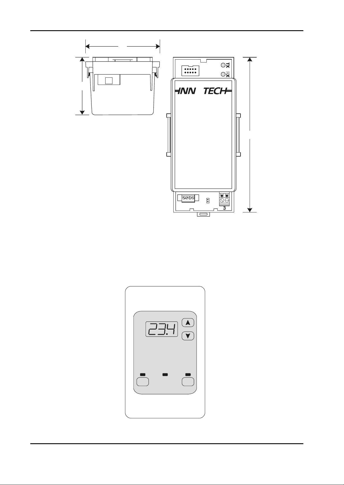
2-2.1.1. Genesis II Digital Controller. The Genesis II Digital Controller is used
only with a Genesis II System. The controller’s case is made of ignition-resistant grade
ABS plastic which meets the Fire Rating requirements of AS420. The unit’s electronic
circuit boards are housed in a two-piece plastic case consisting of a base and a lid. The
Edition 011100
2-1
Page 16
Installation Instructions for Innotech Genesis Systems
plastic base has eight mounting holes; each hole is 4mm in diameter. Not all of the eight
holes are required for mounting, providing the unit is securely installed.
There are four slots in the bottom circuit board (motherboard) - two slots at each end.
These slots facilitate the clamping of the plastic lid to the motherboard. To remove the
plastic lid from the motherboard, press firmly inwards at each end of the plastic lid-piece to
disengage the clip-in fitting and lift away simultaneously (see Figure 2-1). Installation of
the plastic lid is similar to the removal procedure; insert the clip-in fitting at one end of the
plastic lid into the slots provided on the motherboard. Then, clip the opposite end of the
plastic lid into the slots at that end of the motherboard. Pressing the two ends of the plastic
lid together can assist in the operation.
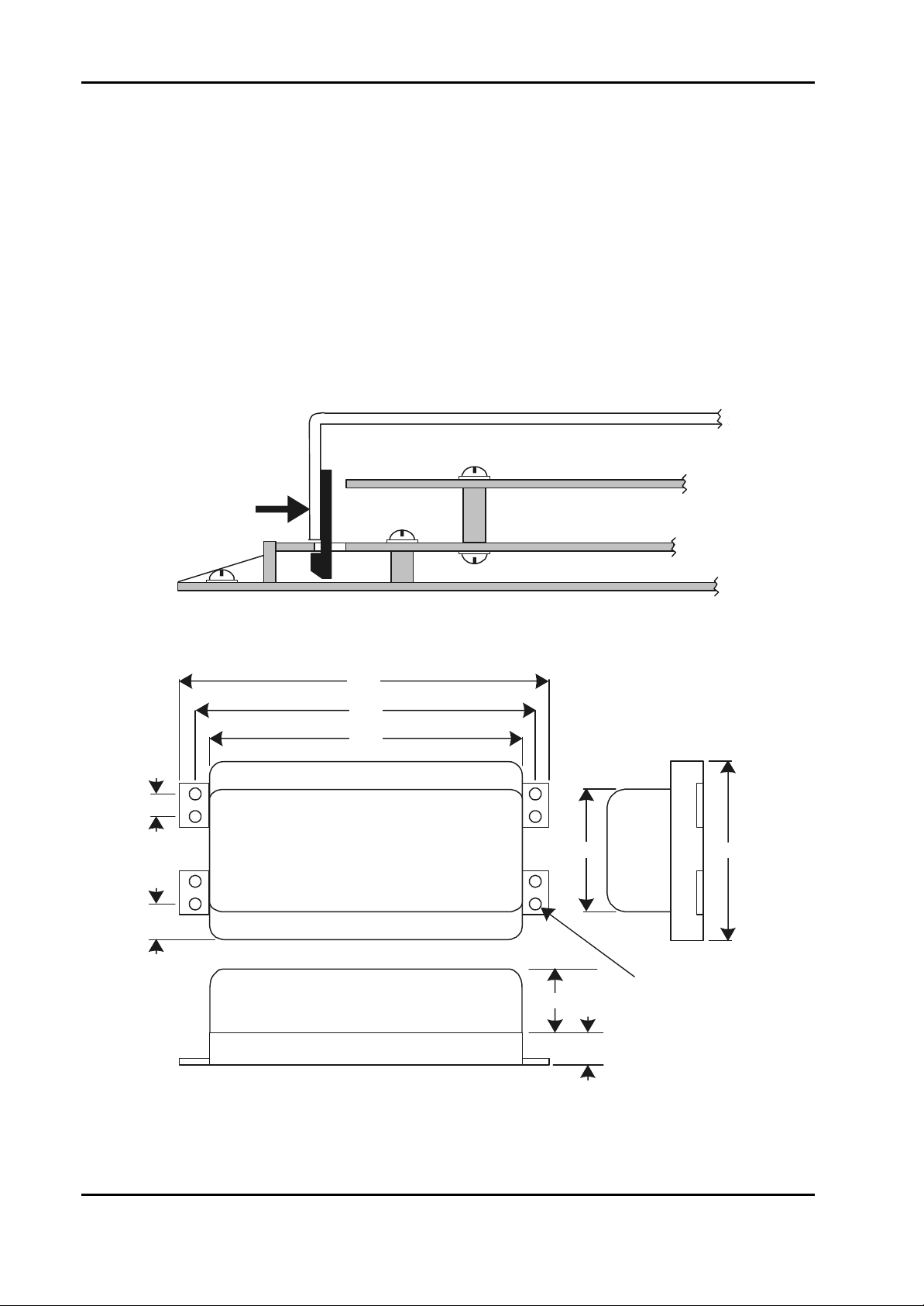
The Digital Controller’s outline dimensions are shown in Figure 2-2.
Plastic Lid Piece
Top Circuit Board
PRESS TO
RELEASE
Motherboard
12
25
Plastic Base Piece
Figure 2-1. Digital Controller Plastic Lid Clamping Details.
308
292
280
140
Mounting Hole
50
Typical of 8
50
180
4mm
2-2
ALL DIMENSIONS ARE IN MILLIMETRES
Figure 2-2. Digital Controller Dimensions.
Edition 011100
Page 17
Installation Instructions for Innotech Genesis Systems
2-2.1.2. Genesis I Digital Controller. The Genesis I Digital Controller is used only
in Genesis I Systems. The main physical difference between the Genesis I and Genesis II
controllers is that the Genesis I Digital Controller does not contain a display or operator’s
keyboard as does the Genesis II controller. This means that, unlike the Genesis II Digital
Controller, providing access to controls and indicators is not a consideration when installing
the Genesis I Digital Controller. The Genesis I and Genesis II Digital Controllers are
similar in all other respects, including dimensions.
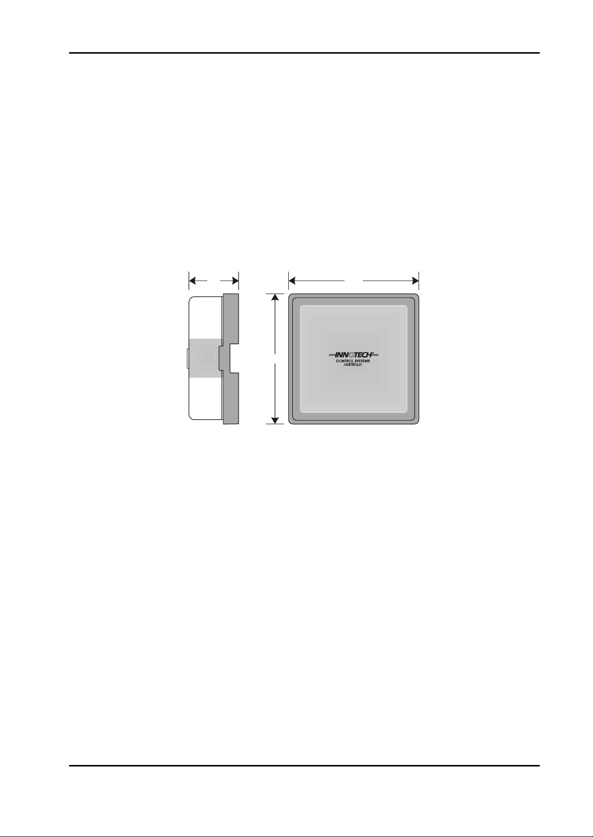
2-2.1.3. Genesis II Mid Points Controller. The GENII MPC Mid Points
Controller module (Figure 2- 3) is a state-of-the-art processing system that performs the
same controller functions as a digital controller. The GEN II MPC can be used in a Genesis
II System as the main controller or as a supporting controller. It is designed for DIN Railmounting inside a control panel. The MPC does not have external controls or indicators.
65
163
163
R
Figure 2-3. Genesis II Mid Points Controller.
2-2.2. EXPANSION MODULES. Expansion modules increase the capability of a
controller by allowing more input and output devices to be connected to it. The following
paragraphs describe two classes of expansion modules: Local Expansion Modules and Remote
Expansion Modules.
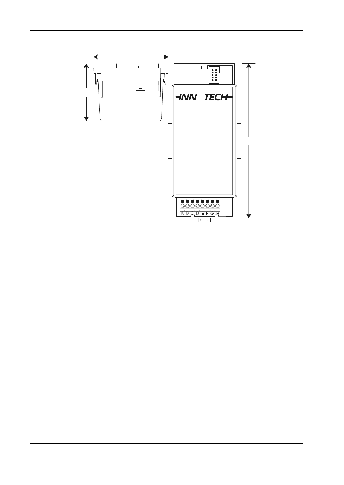
2-2.2.1. Local Expansion Modules. The term: Local Expansion Module (LEM) is
the collective name applied to the following types of units used to configure the hardware to
the customer’s requirements.
• Analogue Input Module (AIM)
• Digital Input Module (DIM)
• Digital Output Module (DOM)
Up to eight LEMs can be included in the system in any combination. They are designed for
easy mounting on standard DIN Rails. A typical LEM is shown in Figure 2-4. The LEM
shown in Figure 2-4 is a Digital Input Module; however the three types of LEM are similar
in appearance and are identical in their dimensions.
There are restrictions on how far apart the LEMs can be from each other and from the
controller; these requirements are explained in Paragraph 2-3.
Edition 011100
2-3
Page 18
Installation Instructions for Innotech Genesis Systems
57
ALL DIMENSIONS ARE
IN MILLIMETRES
75
DIN Rail
Mounted
GENESIS II
DIGITAL INPUT MODULE
R
155
Figure 2-4. Typical Local Expansion Module.
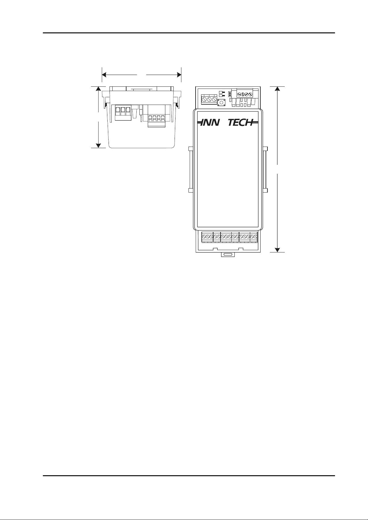
2-2.2.2. Remote Expansion Modules. The term: Remote Expansion Module
(REM) is the collective nomenclature applied to the several types of units used to configure
the hardware to the customer’s requirements. The REMs listed below are similar in
appearance and of the same approximate dimensions as the LEMs and perform the same
basic functions as the LEMs, but from a greater distance. However, REMs and LEMs
cannot be used together with the same Digital Controller or GENII MPC.
• GENII AI REM Analogue Input Module
• GENII AO REM Analogue Output Module
• GENII DI REM Digital Input Module
• GENII OPTO DI REM Opto-Isolated Digital Input Module
• GENII DO REM Digital Output Module (Also called a Relay Output Module)
Figure 2-5 shows a typical REM; the example shown is GENII AI REM. REMs are DIN
Rail-mounted.
In addition to the types of REMs listed above and represented by Figure 2-5, there are three
additional types of REMs or REM-related modules described in the following paragraphs:
• GENII RMI Remote Module Interface
• GENII CS REM Control Station Module
• GENII MP REM Multipoint Module
2-4
Edition 011100
Page 19
Installation Instructions for Innotech Genesis Systems
The system imposes restrictions on the total number and types of REMs that can be used
with a controller. These requirements are explained in Paragraph 2-4.1.
75
57
ALL DIMENSIONS ARE
IN MILLIMETRES
DIN Rail
Mounted
3
12
GEN II AI REM
ABCDEFGHIJKLMN
R
155
O
Figure 2-5. Typical Remote Expansion Module.
2-2.2.2.1. Remote Module Interface. The GENII RMI Remote Module
Interface (Figure 2-6) provides an interface between the Genesis II Digital Controller or
GENII MPC and the REMs. The Remote Module Interface is DIN rail-mounted close to
the controller and the REMs are installed at remote locations. Installation instructions
for the GENII RMI and the REMs are contained in Paragraph 2-4.
Edition 011100
2-5
Page 20
Installation Instructions for Innotech Genesis Systems
75
57
ALL DIMENSIONS ARE
IN MILLIMETRES
DIN Rail
Mounted
GENESIS II
REMOTE MODULE INTERFACE
R
155
Figure 2-6. GENII RMI Remote Module Interface.
2-2.2.2.2. Control Station Module. The GENII CS REM Control Station
Module (Figure 2-7) is housed in a switch plate that mounts in a standard electrical wall
plate at a remote location. Mechanical installation instructions for the GENII CS
Module are not applicable; electrical installation instructions for the module are
contained in Section 3.
On
Off
System
Timer
2-6
Figure 2-7. GENII CS Control Station Module.
Edition 011100
Page 21

Installation Instructions for Innotech Genesis Systems
2-2.2.2.3. Multipoint Module. The GENII MP REM Multipoint Module is a
DIN Rail-mounted device that provides input/output expansion capability for the
associated Genesis II Digital Controller or GENII MPC. It is designed to be located at a
remote location. The GENII MP REM is enclosed in a square case made of flameresistant Astrene M650 IR plastic. It is identical in appearance and dimensions to the
GENII MPC (Figure 2-3).
NOTE
Unless otherwise noted, Installation Instructions are based on the
assumption that the system to be installed is a local Genesis II System
consisting of one Genesis II Digital Controller and three types of
LEMs. Installation Instructions for other types of hardware, such as:
Genesis I Digital Controllers, GENII MPCs, and REMs are contained
in Paragraph 2-4 - Difference Data.
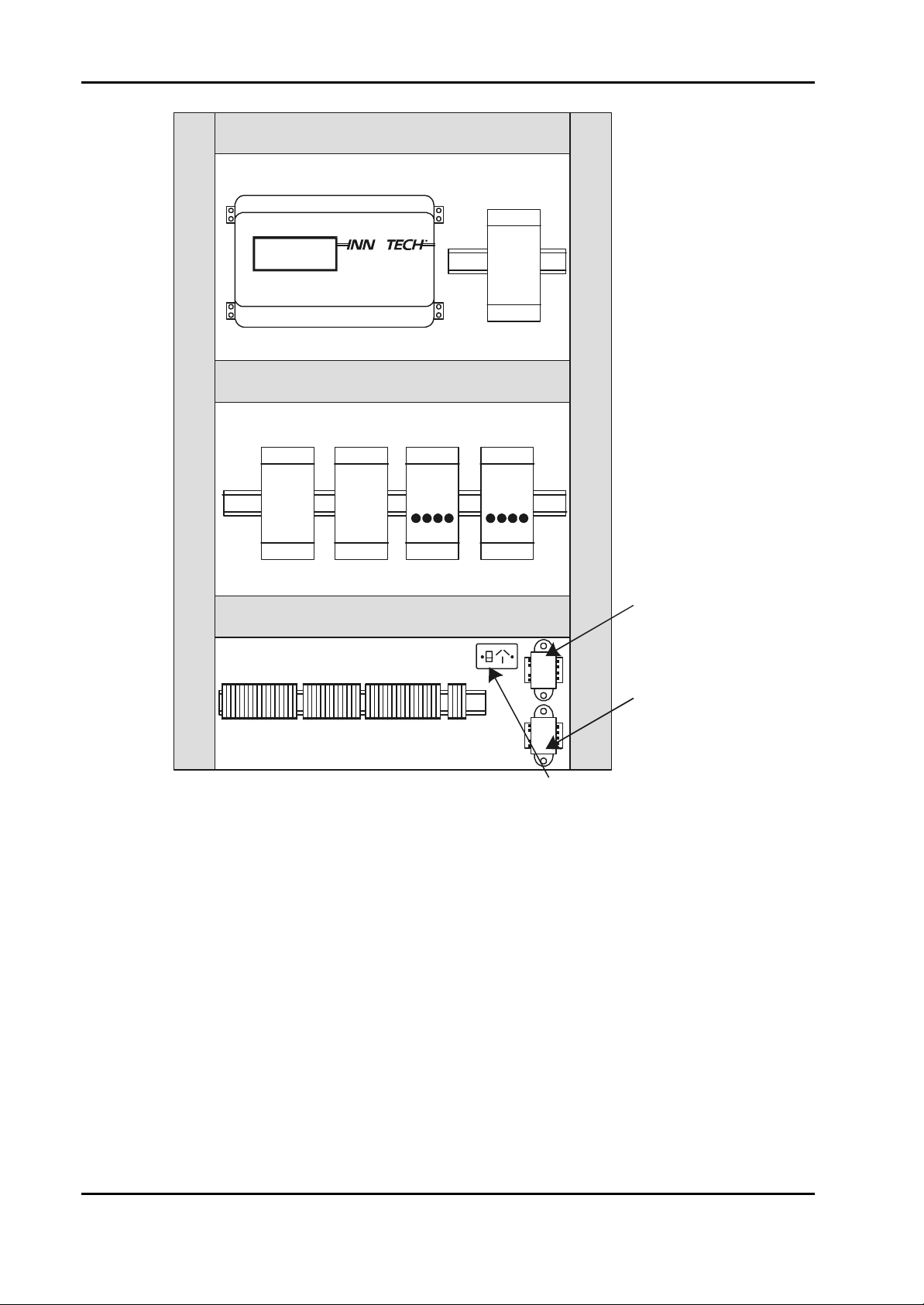
2-3. INSTALLATION INSTRUCTIONS.
A steel enclosure is recommended to contain the system with the aim of minimising EMI from
surrounding equipment. To facilitate the number of cables entering and leaving the enclosure, the
minimum dimensions of slotted cable ducts should be 45mm x 45mm with 65mm clearance from
the cable ducts to the terminals of the units.
Where LEMs are used, every effort should be made to locate these units adjacent to the controller
to minimise problems with connecting cables due to the critical lengths and segregation
requirements.
The communications cable between the Digital Controller and the LEMs is an Innotechmanufactured item; part number GenII LEM Cable. The cable is made in 150mm segments;
therefore, it is important that the LEMs are located as close as possible to the Digital Controller
and placed side-by-side on the DIN rail.
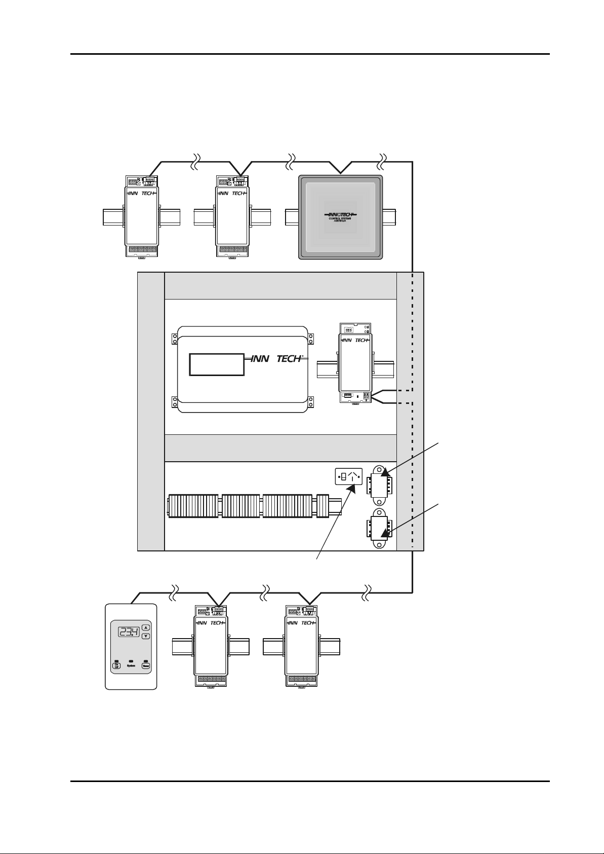
Figure 2-8 shows an example of a typical Genesis System layout in an equipment enclosure.
Edition 011100
2-7
Page 22
Installation Instructions for Innotech Genesis Systems
45mm Slotted Cable Duct
Panel Size
600 X 900mm
45mm Slotted Cable Duct
GENESIS II
R
See Note
45mm Slotted Cable Duct
See Note
D.I.M. D.I.M. D.O.M. D.O.M.
See Note
45mm Slotted Cable Duct
A.I.M.
45mm Slotted Cable Duct
Digital
Controller
Power
Transformer
Auxiliary
Power
Transformer
Terminal Strip
NOTE:
65mm Space Between Duct
Standard Power
Point (Outlet)
and Terminals in These Areas.
Figure 2-8. Typical Enclosure Layout.
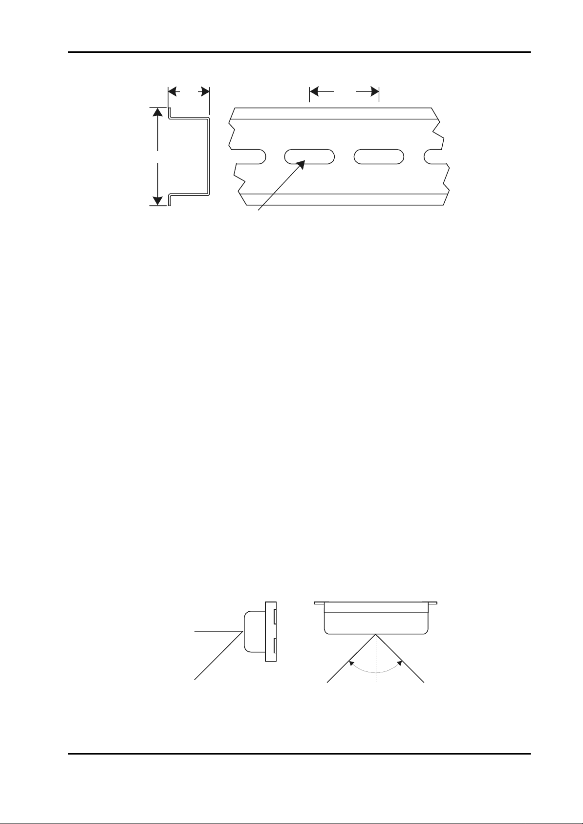
2-3.1. DIN RAILS. The DIN rail is an industry-standard item and is available from a
large number of commercial sources. The rail is usually manufactured from galvanised steel
and may be provided with a finish. It is typically available in 2-metre lengths. DIN rail cutters
are available commercially and are recommended; however, for smaller installations, a
hacksaw may be used to cut the rails to the required length. Figure 2-9 is provided to assist in
planning layout of the LEMs; the figure shows the dimensions of a typical DIN rail section.
2-8
Edition 011100
Page 23
Installation Instructions for Innotech Genesis Systems
15
35
Mounting Slot
18 X 5.2
ALL DIMENSIONS ARE IN MILLIMETRES
Figure 2-9. DIN Rail Dimensions.
25
2-3.2. INSTALLATION GUIDELINES. To ensure continued reliable operation of
the Genesis II System, the following installation guidelines should be observed:
• The Genesis II Digital Controller should be installed in a position that provides easy
access to the front panel and sufficient room for power, and input/output cabling. Also,
the Digital Controller should be mounted such that the controls are in easy reach of the
user.
• Install LEMs as close as possible to the Digital Controller and side-by-side on the DIN
rail. Refer to Paragraph 2-3 and Figure 2-8.
• Placement of the Genesis II Digital Controller should take into account the optimum
viewing angle of the Liquid Crystal Display (LCD), which is approximately 45o vertically
and 90o horizontally (see Figure 2-10).
• Do not mount any unit of the system near high voltage, high current cables or sources of
strong radio frequency emissions such as transmitter antenna cables.
• The ambient temperature of the Digital Controller and LEMs at the installation site should
not exceed the 0-40ºC temperature range. Ideally, the installation site should have a stable
ambient temperature close to 20oC.
• Mount the units in an area with minimum vibration and minimum exposure to mechanical
damage.
SIDE VIEW TOP VIEW
45
DEGREES
Edition 011100
90 DEGREES
Figure 2-10. Digital Controller Display, Viewing Angles.
2-9
Page 24
Installation Instructions for Innotech Genesis Systems
2-4. DIFFERENCE DATA.
This paragraph contains difference data unique to installation of the Genesis I Digital Controller,
the GENII MPC, Genesis II REMs and related devices. Installation Instructions provided in
Paragraph 2-3 are applicable except where stated otherwise.
2-4.1. REM LIMITATIONS. The following limitations apply to the installation of
REMs:
• LEMs and REMs cannot be used with the same Digital Controller or GENII MPC.
• REMs can only be used with Genesis II Digital Controllers that have been upgraded to
Version 4.0 firmware.
NOTE
The Version 4.0 Configuration Software automatically configures the
Digital Controller and produces a printout which lists the types and
quantities of REMs that can be used with a given Digital Controller.
The following information provides generalised REM type/quantity
requirements that can be used for planning purposes.
• Only one GENII RMI Remote Module Interface can be used with a Genesis II Digital
Controller or GENII MPC. It must be installed adjacent to the digital controller/MPC
• Up to 15 REMs can be connected to a single GENII RMI. However, each REM has a
Resource Count that represents its requirements for controller resources. In no case can
the Resource Count for a Digital Controller/GENII MPC exceed 36. Refer to Table 2-1
for a list of REM Resource Counts.
• The REMs must be installed within 500 metres of the RMI.
Table 2-1. REM Resource Counts.
TYPE OF REM RESOURCE
COUNT
GENII AI Analogue Input Module 6
GENII AO Analogue Output Module 3
GENII DI Digital Input Module 1
GENII OPTO DI Opto Isolated Digital Input Module 1
GENII DO Digital Output Module 1
GENII CS Control Station Module 4
GENII MP Multipoint Module 3
NOTE: The following examples illustrate the maximum number of REMs
allowed per digital controller or MPC:
a. 3 AIMs (3 x 6), 3 AOMs (3 x 3), 4 DIMs (4 x 1), 5 DOMs (5 x 1) = 36
(Maximum allowed Resource Count)
b. 5 DIMs (1 x 5), 5 OPTO DIs (1 x 5), 5 DOMs (1 x 5) = Resource Count 15
but maximum number of REMs allowed is 15
2-10
Edition 011100
Page 25
Installation Instructions for Innotech Genesis Systems
2-4.2. TYPICAL INSTALLATION. Figure 2-11 shows an example of a typical
installation using REMs.
GEN II AI
REM
(Note 3)
3
12
R
GEN II AIM REM
ABCDEFGHIJKLMNO
GEN II AO
REM
(Note 3)
3
12
R
GEN II AIM REM
ABCDEFGHIJKLMNO
45mm Slotted Cable Duct
Panel Size 600 X 900MM
GENESIS II
DIGITAL
CONTROLLER
Note 4
45mm Slotted Cable Duct
GEN II MP
REM
(Note 3)
GENESIS II
R
REMOTE MODULE INTERFACE
GEN II
R
RMI
Notes
1, 2
R
Digital
Controller
Power
Transformer
GEN II CS
REM
(Note 3)
45mm Slotted Cable Duct
Note 4
Terminal Strip
Standard Power Point (Outlet)
123
R
GEN II AIM REM
ABCDEFGHIJKLMNO
GEN II DO
REM
(Note 3)
123
GEN II AIM REM
ABCDEFGHIJKLMNO
GEN II DI
REM
(Note 3)
Auxiliary
Power
Transformer
Notes
1, 2
R
1.
See Appendix A for Wiring
NOTES
Requirements.
Cable run not to exceed
2.
500 metres.
See Paragraph 2-4.1 for
3.
limitations on number and
types of REMs.
65mm space between duct
4.
and terminals.
Edition 011100
Figure 2-11. Typical Remote System Layout.
2-11
Page 26

Installation Instructions for Innotech Genesis Systems
2-4.3. ADDITIONAL INSTALLATION GUIDELINES. For installation of the
Genesis II Digital Controller or GENII MPC system with REMs, observe the applicable
installation guidelines in Paragraph 2-3.2 and the following specific guidelines:
• Although the Genesis II Digital Controller should be mounted in a location providing easy
access to operating controls and indicators, this requirement does not apply to the Genesis
I Digital Controller and GENII MPC which have no external controls or indicators.
• Ensure the Digital Controller has been upgraded to Version 4.0 firmware to support the
REMs.
• Install the GENII RMI on a DIN rail mounting adjacent to the Digital Controller or GENII
MPC. The cable between the RMI and the Digital Controller/MPC must not exceed 1
metre in length.
• The Digital Controller/MPI can have only one GENII RMI connected to it.
• Local Expansion Modules cannot be connected to a Digital Controller/MPC that has a
GENII RMI module connected to it.
• REMs should be mounted in locations such that the cable run between the GENII RMI
and the REMs does not exceed 500 metres in length.
• REM units should be mounted on DIN rails in cabinets approved for switchgear or
industrial control equipment.
• Ensure that the types and quantities of REMs assigned to a controller are in accordance
with Paragraph 2-4.1.
2-12
Edition 011100
Page 27

Installation Instructions for Innotech Genesis Systems
SECTION 3- ELECTRICAL INSTALLATION
3-1. INTRODUCTION.
This section of the manual contains instructions and related data to facilitate the electrical
installation of the Genesis I or Genesis II System. Because of the electrical similarities of the two
systems, instructions contained in this section apply equally to the Genesis I and Genesis II
Systems, except where otherwise noted.
Because of the designed-in flexibility of the Genesis System, it can be installed in a wide variety
of configurations, depending on the user’s preference. For this reason it is not possible to include
all the various installation configurations in this manual. Instead, this manual provides examples
of installations that are considered typical. Innotech recognises that the installation examples
described in this manual may not be in total agreement with the user’s requirements. However,
information in this document should be used as a guide for all installations, regardless of whether
the specific circumstances match the examples given. In all cases, installation personnel should
familiarise themselves with the information contained in this section.
NOTE
If required, additional installation recommendations can be obtained
from Innotech Control Systems Australia upon request.
This section of the technical manual contains the following specific information:
• Electrical Installation Practices of a general nature
• Wiring information for controllers (Genesis I and II Digital Controllers and Genesis II Mid
Points Controller)
• Wiring information for expansion modules (Local Expansion Modules and Remote
Expansion Modules)
3-2. ELECTRICAL INSTALLATION PRACTICES.
This paragraph provides general information useable to qualified personnel installing the Genesis
Systems. More detailed information for wiring of controllers and expansion modules is contained
in subsequent paragraphs.
All wiring between the controller/expansion modules and system input/output devices, such as
sensors, fans, compressors, must be in accordance with the instructions in the applicable
instruction manual or data sheet.
ELECTRICAL POWER TO THE SYSTEM MUST BE TURNED
OFF THROUGHOUT THE INSTALLATION PROCESS. DO NOT
APPLY POWER TO ANY PART OF THE SYSTEM UNTIL READY
FOR COMMISSIONING (SEE SECTION 4).
Edition 011100
CAUTION
3-1
Page 28

Installation Instructions for Innotech Genesis Systems
NOTE
If any data presented in this manual disagrees with information in the
applicable instruction manual, information in the manufacturer’s
instruction manual takes precedence. Customers are encouraged to
contact Innotech Control Systems Australia for further information or
clarification of information presented herein. Use the address or
phone/fax number shown on the cover of this instruction manual.
Cabling plays an important role in the installation of the Genesis Systems. The following general
cabling guidelines should be observed:
• In all cases, use electromagnetic-shielded cable for sensor wiring.
• When necessary to protect cabling from physical damage, both shielding and physical
protection may be provided by running the cable in a metal conduit. Alternatively, use steel
wire armoured (SWA) cable, which also contains an electromagnetic shield.
• Avoid running cables in the vicinity of high voltage power cables or cables carrying switching
voltages/currents. This especially applies to sensor signal cables.
• Interconnecting cables must have multi-strand conductors with a cross-sectional area of 1mm
for each conductor.
• The earth cable to Genesis II enclosures must be 2.5mm
• For analogue inputs to the controller, a 16-conductor (0.5mm
2
.
2
) shielded cable is required.
2
Table 3-1 provides assistance in determining the cabling requirements for various installation
configurations. It shows the dimensions, wire gauge designations and resistance values per unit
length for common wire sizes. Use Table 3-1 to determine specific cabling requirements for your
installation.
Table 3-1. Nominal Resistance for Wire Sizes at 20°C.
CONDUCTOR
AREA (mm2)
DIAMETER
(mm)
NEAREST
SWG OR
BWG
NEAREST
AWG
OHMS
PER 100
METRES
0.5 0.80 21 20 3.44
1.0 1.13 18 17 1.72
1.5 1.38 17 15 1.15
2.0 1.60 16 14 0.86
2.5 1.78 15 13 0.69
Notes:
1. SWG = Standard Wire Gauge, BWG = British Wire Gauge, AWG = American Wire Gauge.
2. All SWG, BWG & AWG numbers are for the next largest wire if a direct equivalent to the mm
wire size is not available.
2
3-3. CONTROLLER WIRING.
The following paragraphs contain input/output connection information for the Genesis II Digital
Controller, the Genesis II Mid Points Controller and the Genesis I Digital Controller. The
Genesis II Configuration Software, which is used to configure and program the controller,
3-2
Edition 011100
Page 29
Installation Instructions for Innotech Genesis Systems
automatically produces a wiring diagram and materials list for the specific application. The
wiring diagram and materials list can be easily printed out and used for reference. Figure 3-1
shows a typical computer-generated wiring diagram. A printout of the wiring diagram and
materials list is usually provided at the time of hardware delivery.
NO NCCNCCNO NCCNO NCCNO NCCNO NCCNO NCCNO NO
SA Fan
Comp #1
DO #1 DO #2 DO #3 DO #4 DO #5 DO #6 DO #7
DIGITAL OUTPUTS
+
GND+24
21
-
Comp #2
Fault!
Alarm Panel Light
Air Compressor
Security Lights
Sprinkler Solenoid
VAV #3
SSR #3
VAV #4
SSR #4
Siren
DIGITAL INPUTS
DI1 DI2 DI3 DI4 DI5 DI6 DI7 DI8
Normally Open
Normally Open
Normally Closed
56 5758 59 60 61 62555453525150494847464544434241
DO #8
63 64
NCC
576 8 13 161514
838281
84
8887868580797877
Global Net
+
90 91 92 9389
-
C
+
-
01 03 04 05 06 07 08 09 10 11 12 13 14 15 16
65
1324 9 121110
66
6867
69
727170
7473
75
76
RS-485
VAV #1
SSR #1
VAV #2
SSR #2
VAV #5
SSR #5
ANALOGUE
OUTPUTS
RS-485
+
90 9189
+
93 9492
-
-
G
G
G
N
Alternative
Plug Style
ANALOGUE INPUTS
SCREEN MUST
GO HERE!
TD1: 0-250 µAmps
TD1: 0-250 µAmps
TD1: 0-250 µAmps
TD1: 0-250 µAmps
TD1: 0-250 µAmps
TD1: 0-250 µAmps
TH7: Thermistor
AIM: <external>
RS-232
+
--------
+
+
+
+
+
+
+
SCR
SS
AI1 AI2 AI3 AI4 AI5 AI6 AI7 AI8
+
--------
+
+
+
+
+
+
+
12V PC
+
+
--
LEM COMMS
1817161514131211109876543
2019
36353433323130292827262524232221
37 38 3940
Air Flow Switch
A/H Button
Fridge Door Open
Sensor #1
Innotech Temperture
Sensor #2
Innotech Temperture
Sensor #3
Innotech Temperture
Sensor #4
Innotech Temperture
Sensor #5
Innotech Temperture
Sensor #6
Innotech Temperture
Switchboard Temp
Thermistor, Philips 10k
AI LEM #1, Terminal 3
NC
Innotech T emperature
Innotech T emperature
Innotech T emperature
Innotech T emperature
Innotech T emperature
Sensor #7
Sensor #8
Sensor #9
Sensor #10
Sensor #11
Edition 011100
GENESIS II DDCINNOTECH
(Wiring diagram - bottom board)
123
A1<not used>
SCREEN
DDC Terminal 35
JIHGFEDCBA
AI5 AI6 AI7 AI8 AI9
+
-----
+
+
+
+
TD1: 0-250 µAmps
TD1: 0-250 µAmps
TD1: 0-250 µAmps
TD1: 0-250 µAmps
TD1: 0-250 µAmps
TD1: 0-250 µAmps
Address
jumpers
A0
A2
A1
Local Expansion Module #1 (AI)
Figure 3-1. Computer-Generated Wiring Diagram, Example.
3-3
Page 30
Installation Instructions for Innotech Genesis Systems
M
CTOR
M
CTOR
M
CTOR
M
CTOR
M
CTOR
RS
M
CTOR
M
CTOR
M
CTOR
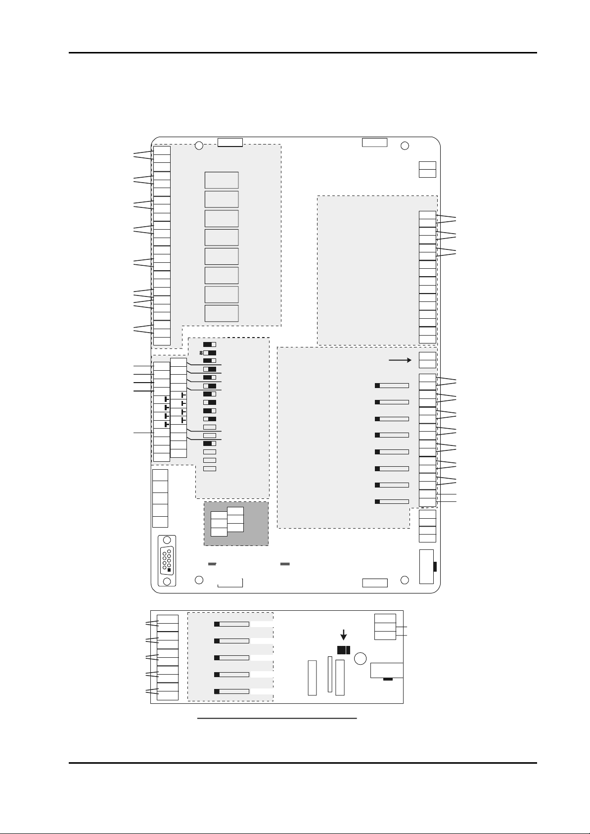
3-3.1. GENESIS II DIGITAL CONTROLLER. Figure 3-2 shows the
input/output connection groups for the Genesis II Digital Controller. The controller uses
Phoenix type plug-in terminal strips located around the controller’s perimeter. Both single row
and double row terminals are used. Terminals are grouped by function as follows:
• Power Input(Paragraph 3-3.1.1)
• Digital Inputs (Paragraph 3-3.1.2)
• Digital Outputs (Paragraph 3-3.1.3)
• Analogue Inputs (Paragraph 3-3.1.4)
• Analogue Outputs (Paragraph 3-3.1.5)
• Pulse Counter Inputs (Paragraph 3-3.1.6)
• Local/Remote Expansion Modules (LEM/REM) Connector (Paragraph 3-3.1.7)
• RS485 Communications (Comms) Terminals (Appendix A)
• RS232 Connector (Appendix A)
24Vac POWERSCREENSPULSE INPUTSDIGITAL INPUTSANALOGUE INPUTS
LEM/RE
POWER INPUTSCREENSPULSE INPUTSDIGITAL INPUTSANALOGUE INPUTS
LEM/RE
POWER INPUTSCREENSPULSE INPUTSDIGITAL INPUTSANALOGUE INPUTS
LEM/RE
POWER INPUTSCREENSPULSE INPUTSDIGITAL INPUTSANALOGUE INPUTS
LEM/RE
POWER INPUTSCREENSPULSE INPUTSDIGITAL INPUTSANALOGUE INPUTS
LEM/RE
L1L2L3
POWER INPUTSCREENSPULSE INPUTSDIGITAL INPUTSANALOGUE INPUTS
LEM/RE
POWER INPUTSCREENSPULSE INPUTSDIGITAL INPUTSANALOGUE INPUTS
LEM/RE
POWER INPUTSCREENSPULSE INPUTSDIGITAL INPUTSANALOGUE INPUTS
LEM/RE
101112131415161718345678919202829303132333435362122232425262737383940
12
CONNE
101112131415161718345678919202829303132333435362122232425262737383940
12
CONNE
101112131415161718345678919202829303132333435362122232425262737383940
12
CONNE
101112131415161718345678919202829303132333435362122232425262737383940
12
CONNE
101112131415161718345678919202829303132333435362122232425262737383940
12
CONNE
TOHEATERSTOHEATERSTOHEATE
101112131415161718345678919202829303132333435362122232425262737383940
12
CONNE
101112131415161718345678919202829303132333435362122232425262737383940
12
CONNE
101112131415161718345678919202829303132333435362122232425262737383940
12
CONNE
12
ANALOGUEOUTPUT
3+ve4123+ve4123+ve4+
TERMINALS
484950515253545556575859606162636441424344454647727374757665666768697071899091
484950515253545556575859606162636441424344454647727374757665666768697071899091
484950515253545556575859606162636441424344454647727374757665666768697071899091
484950515253545556575859606162636441424344454647727374757665666768697071899091
484950515253545556575859606162636441424344454647727374757665666768697071899091
484950515253545556575859606162636441424344454647727374757665666768697071899091
484950515253545556575859606162636441424344454647727374757665666768697071899091
484950515253545556575859606162636441424344454647727374757665666768697071899091
POWER INPUT SCREENS PULSE INPUTS
DIGITAL INPUTS
ANALOGUE INPUTS
LEM/REM
CONNECTOR
12
48 49 5051 52 53 54 55 5657 58 59 606162 63 6441 42 43 4445 4647
10 11 12 13 1415 1617 183456789 19 20 28 29 30 31 3233 34 35 3621 22 23 2425 2627 37 38 39 40
89 90 91
75 7665 66 67 6869 70
727374
71
DIGITAL OUTPUTS
ANALOGUE
OUTPUTS
RS 485
COMMS
RS 232
CONNECTOR
Figure 3-2. Genesis II Digital Controller Input/Output Terminals.
3-4
Edition 011100
Page 31

Installation Instructions for Innotech Genesis Systems
3-3.1.1. Power Input. The Genesis II Digital Controller power requirements are:
• 24Vac ±10%, 50/60Hz at 1.0A, or
• 24Vdc ±10%, at 0.75A (Factory Modification is Required)
For 24Vac supply voltages, a safety transformer with a nominal rating of 30VA must be
used for the Digital Controller. The transformer must be in compliance with EN60742,
designed for 100% duty and fused in compliance with local safety regulations. A single
transformer may be used to supply voltage to more than one unit (such as a Digital
Controller and associated expansion modules) providing the planned load is well within the
transformer’s rating.
The transformer output terminal designated as AC Neutral must be solidly earthed to the
enclosure’s main earth link.
Power input terminals are Terminals 1 and 2 and connected as follows:
Terminal AC Supply DC Supply
1 24Vac +24Vdc
2 0Vac
(Neutral)
Note: Resistance between Terminal 2 and
earth must be 3 Ohms, or less
-24Vdc
3-3.1.2. Digital Inputs. The Genesis II Digital Controller’s eight digital input
channels (Terminals 3–18) provide the capability of directly interfacing to digital input
signal sources such as pushbutton switches and relay contacts. Because each digital input
channel is isolated, the power source for the signal must be external to the controller. This
signal source can be AC or DC. If the source is AC, it can be provided by the auxiliary
transformer. Signal power requirements are:
• 24Vac ± 15%, or
• 24Vdc ± 15% (Factory Modification Required)
There are two terminals associated with each digital input channel. If an external DC signal
source is used, the odd-numbered (left) terminal must be wired as positive and the evennumbered (right) terminal as negative.
Refer to Table 3-2 for digital input terminal number assignments. Signal names assigned to
the terminals are DI1+/− through DI8+/−. DI stands for Digital Input, the numeral
represents the channel number and the + or − indicates the signal polarity when using a DC
signal power source.
Edition 011100
3-5
Page 32

Installation Instructions for Innotech Genesis Systems
Table 3-2. Genesis II Digital Controller Digital Inputs.
TERMINAL SIGNAL TERMINAL SIGNAL
POSITIVE SIDE NEGATIVE SIDE
3 DI1+ 4 DI1−
5 DI2+ 6 DI2−
7 DI3+ 8 DI3−
9 DI4+ 10 DI4−
11 DI5+ 12 DI5−
13 DI6+ 14 DI6−
15 DI7+ 16 DI7−
17 DI8+ 18 DI8−
3-3.1.3. Digital Outputs. Each of the Genesis II Digital Controller’s eight digital
output channels (Terminals 41–64) consists of a single-pole, double-throw (SPDT) relay.
Three terminals assigned to each channel represent the associated relay’s Normally Open
(NO), Common (C) and Normally Closed (NC) contacts.
Digital output relay contacts are rated at 240Vac, 2A. Good practice is to use pilot relays
for the actual switching functions, particularly when it applies to inductive loads such as
coils, solenoids and motors. This protects the relays of the digital output channel and has
the advantage of allowing the pilot relays to be installed adjacent to the controlling
switchgear.
Refer to Table 3-3 for digital output terminal number assignments.
Table 3-3. Genesis II Digital Controller Digital Outputs.
TERMINAL SIGNAL TERMINAL SIGNAL TERMINAL SIGNAL
NORMALLY
OPEN (NO)
41 DO1NO 42 DO1C 43 DO1NC
44 DO2NO 45 DO2C 46 DO2NC
47 DO3NO 48 DO3C 49 DO3NC
50 DO4NO 51 DO4C 52 DO4NC
53 DO5NO 54 DO5C 55 DO5NC
56 DO6NO 57 DO6C 58 DO6NC
COMMON (C)
NORMALLY
CLOSED (NC)
3-6
59 DO7NO 60 DO7C 61 DO7NC
62 DO8NO 63 DO8C 64 DO8NC
Edition 011100
Page 33

Installation Instructions for Innotech Genesis Systems
3-3.1.4. Analogue Inputs. The Genesis II Digital Controller’s eight analogue input
channels (Terminals 21-36) allow the direct interface of various analogue inputs, such as
Thermistor, 0-10Vdc, 0-5Vdc and 4-20mA signals. Each analogue input channel is
configured to the type of input by the use of Analogue Input Signal Conditioners (AISCs).
These are small plug inserts installed during system commissioning (Section 4).
CAUTION
SPECIAL CONSIDERATION MUST BE MADE WHEN USING
LOOP-POWERED 4-20MA INPUTS. BECAUSE THIS TYPE OF
INPUT DRAWS 20MA FROM THE DIGITAL CONTROLLER, A
MAXIMUM OF TWO INPUTS OF THIS TYPE MAY BE USED.
THIS TYPE OF INPUT MUST NOT BE USED ON LOCAL OR
REMOTE EXPANSION MODULES.
NOTE
Terminals 19 and 20 (Figure 3-2) are provided for terminating
analogue cable screens.
There are two terminals associated with each of the eight analogue input channels.
Normally, the odd-numbered (positive) terminal is used for the active analogue input signal
from the sensor. The even-numbered (negative) terminal is used to provide the stimulation
for the sensor or a voltage reference (such as 0 Volts) for an active transducer.
Due to the sensitivity of the analogue input signals, screened cable must be used. The
screens should be terminated at Terminals 19 or 20.
Refer to Table 3-4 for analogue input terminal number assignments. Signal names assigned
to the terminals are AI1+/− through AI8+/−. AI stands for Analogue Input; the numeral
represents the channel number. The + indicates the active signal and the − indicates the
signal reference/return.
Table 3-4. Genesis II Digital Controller Analogue Inputs.
TERMINAL SIGNAL TERMINAL SIGNAL
ACTIVE REFERENCE
21 AI1+ 22 AI1−
23 AI2+ 24 AI2−
Edition 011100
25 AI3+ 26 AI3−
27 AI4+ 28 AI4−
29 AI5+ 30 AI5−
31 AI6+ 32 AI6−
33 AI7+ 34 AI7−
35 AI8+ 36 AI8−
3-7
Page 34

Installation Instructions for Innotech Genesis Systems
RS
RS
3-3.1.5. Analogue Outputs. Sixteen analogue output channels are provided. Each
channel can be configured, through the Genesis II Configuration Software, to operate in
either the Variable Mode or the Heat Valve Mode.
In the Variable Mode, the output is a voltage-analogue signal varying from 0 to +10 Volts
with a maximum current rating of 5mA. In the Heat Valve Mode, the output signal consists
of Pulse-Width Modulated (PWM), 0-10V, high-speed pulses at 5mA. For a description of
PWM as it applies to Heat Valve Operation, refer to the Innotech Genesis II Direct Digital
Controller User Manual.
When using PWM outputs, up to three solid state relays, connected in series, may be used
on each Heat Valve-configured analogue output channel. See Figure 3-3. A maximum of
eight analogue output channels can be applied to Heat Valve operation. For more than eight
Heat Valve outputs, it is recommended that Models IHV4002 or IHV4004 Heat Valves for
Solid State Relays be used. These heat valves are driven by the Digital Controller’s
analogue output channel in the Variable Mode. For more information on these devices,
refer to Data Sheet DS3.31 for Type IHV Heat Valves.
L1L2L3
L1L2L3
TOHEATERSTOHEATERSTOHEATE
TOHEATERSTOHEATERSTOHEATE
12
ANALOGUEOUTPUT
12
ANALOGUEOUTPUT
3+ve4123+ve4123+ve4+
TERMINALS
3+ve4123+ve4123+ve4+
TERMINALS
L3
TO
HEATERS
12
ANALOGUE
L1 L2
TO
HEATERS
12
12
TO
HEATERS
OUTPUT
TERMINALS
-
+
3+ve 4
3+ve 4
3+ve 4
Figure 3-3. Driving Multiple Solid-State Relays.
Refer to Table 3-5 for analogue output terminal numbers. There are 16 analogue active
signal terminals (AO1 through AO16), one for each channel and eight return (Common)
terminals. The fewer number of Common terminals is intended to reduce the overall
number of terminals.
Cable screening may be terminated into the Screens Terminals (19 and 20), space
permitting. Alternatively, all cable screens can be combined by soldering within the slotted
cable-routing ducts with a common 1mm2-earth lead connected to Terminals 19 or 20.
3-8
Edition 011100
Page 35

Installation Instructions for Innotech Genesis Systems
Table 3-5. Genesis II Digital Controller Analogue Outputs.
TERMINAL SIGNAL TERMINAL SIGNAL
65 AO1 77 AO5
66 AO2 78 AO6
67 AO3 79 AO7
68 AO4 80 AO8
69 Common 81 Common
70 Common 82 Common
71 Common 83 Common
72 Common 84 Common
73 AO9 85 AO13
74 AO10 86 AO14
75 AO11 87 AO15
76 AO12 88 AO16
3-3.1.6. Pulse Counter Inputs. A single, high-speed digital input is provided to
facilitate the counting of rectangular wave signals (0-12Vdc, from DC up to 25kHz). Refer
to Table 3-6 for terminal number assignments. Terminals 37 and 38 provide 12Vdc power
to the pulse source, if required. Terminals 39 and 40 are the pulse-input terminals. The
input is polarity sensitive so it is important that correct polarity be observed.
Table 3-6. Pulse Counter Input Terminals.
TERMINA
L
37 +12Vdc to Pulse Source
38 –12Vdc to Pulse Source
39 + Pulse Input
40 – Pulse Input
SIGNAL
3-3.1.7. LEM/REM Connector. The LEM/REM connector is a 10-pin ribbon cable
connector that provides access between the Digital Controller and the expansion modules.
NOTE
When expansion modules are used with a Digital Controller, LEMs
and REMs must not be mixed. Modules used may be either LEMs or
REMs, but not both.
Connectors along the cable are spaced at 150mm intervals; therefore it is critical that the
LEMs are located as close as possible to the Digital Controller and to each other.
REMs access to the Digital Controller is through a GENII RMI Remote Module Interface
Unit. The RMI is installed close to the Digital Controller and connects to it by a short
Edition 011100
3-9
Page 36

Installation Instructions for Innotech Genesis Systems
CTOR
M
CTOR
H
MS
H
MS
H
MS
ribbon cable at the LEM/REM Connector. The individual REMs are connected to the RMI
by means of an RS 485 Comms cabling arrangement as explained elsewhere in this section.
3-3.2. GENESIS II MID POINTS CONTROLLER. Figure 3-4 shows the
input/output connection groups for the Genesis II Mid Points Controller (MPC). The MPC
uses terminal strips located around the controller’s perimeter. Terminals are grouped by
function as follows:
• Power (Paragraph 3-3.2.1)
• Digital Inputs (Paragraph 3-3.2.2)
• Digital Outputs (Paragraph 3-3.2.3)
• Analogue Inputs (Paragraph 3-3.2.4)
• Analogue Outputs (Paragraph 3-3.2.5)
• REM/LEM Connector – same as for the Digital Controller. See Paragraph 3-3.1.7.
• RS485 Comms Terminals (Appendix A)
24Vac POWERSCREENSDIGITAL INPUTSANALOGUE INPUTS
LEM
1011121314151617183456789192028293031323334353621222324252627
12
• RS23
24Vac POWERSCREENSPULSE INPUTSDIGITAL INPUTSANALOGUE INPUTS
LEM/RE
DIGITAL INPUTSANALOGUE INPUTS
DIGITAL INPUTSANALOGUE INPUTS
DIGITAL INPUTSANALOGUE INPUTS
101112131415161718345678919202829303132333435362122232425262737383940
12
CONNE
POWER+24V0VEARTH123RS232GEN II MPCSCREENANALOG INPUTSA11A12A13A14
INNOTEC
D14++DIGITAL INPUTSD11D12D13
POWERSCREENS
RS 232CONNECTOR
POWER+24V0VEARTH123RS232GEN II MPCSCREENANALOG INPUTSA11A12A13A14
INNOTEC
D14++DIGITAL INPUTSD11D12D13
POWERSCREENS
RS 232CONNECTOR
POWER+24V0VEARTH123RS232GEN II MPCSCREENANALOG INPUTSA11A12A13A14
INNOTEC
D14++DIGITAL INPUTSD11D12D13
POWERSCREENS
RS 232CONNECTOR
++++
++
++++
++
++++
++
REM/LEMCONNECTOR
REM/LEMCONNECTOR
REM/LEMCONNECTOR
484950515253545556575859606162636441424344454647727374757665666768697071899091
D01D02D03DO4DO5DO6DO7DO8NONONONONONONONOCOMCOMCOMCOMCOMCOMCOMCOMDIGITAL OUTPUTSAO1AO2AO3AO4SCREEN++++ANALOG OUTPUTNETGLOBALSCRN++RS485 COM
D01D02D03DO4DO5DO6DO7DO8NONONONONONONONOCOMCOMCOMCOMCOMCOMCOMCOMDIGITAL OUTPUTSAO1AO2AO3AO4SCREEN++++ANALOG OUTPUTNETGLOBALSCRN++RS485 COM
D01D02D03DO4DO5DO6DO7DO8NONONONONONONONOCOMCOMCOMCOMCOMCOMCOMCOMDIGITAL OUTPUTSAO1AO2AO3AO4SCREEN++++ANALOG OUTPUTNETGLOBALSCRN++RS485 COM
CONNE
4850515354565759606263414244454778656667686970778990919293
2 Connector (Appendix A)
DIGITAL INPUTS ANALOGUE INPUTS
POWER SCREENS
POWER
+24V 0V EARTH
123 RS232
DIGITAL INPUTS
D11 D12 D13
---
++
++
D14
SCREEN
-
ANALOG INPUTS
A11 A12 A13 A14
----
++++
INNOTECH
GEN II MPC
REM/LEM
CONNECTOR
NO NO NO NO NO NO NO NOCOM COM COM COM COM COM COM COM
D01 D02 D03 DO4 DO5 DO6 DO7 DO8
DIGITAL OUTPUTS
SCREEN
++ ++
AO1AO2 AO3 AO4
ANALOG OUTPUT
RS485 COMMS
RS 232
CONNECTOR
SCRN
-
+-+
NET GLOBAL
DIGITAL OUTPUTS
ANALOGUE
OUTPUTS
RS 485
COMMS
Figure 3-4. Genesis II MPC Input/Output Terminals.
3-10
Edition 011100
Page 37

Installation Instructions for Innotech Genesis Systems
NOTE
Because much of the MPC’s input/output connection information is
similar to that of the Genesis II Digital Controller, the following
paragraphs make frequent reference to related paragraphs in the
Genesis II Digital Controller section. Therefore, readers should
familiarise themselves with the types of data contained in Paragraph
3-3.1 and its subparagraphs before reading further.
3-3.2.1. Power Input. The Genesis II MPC power requirements are the same as for
the Genesis II Digital Controller, except that the MPC contains a third power terminal
(Terminal 3) which is an earth connection point. This is an independent earth connection
point and is in addition to the earthed AC Neutral at Terminal 2. Refer to Paragraph 3-
3.1.1.
3-3.2.2. Digital Inputs. The Genesis II MPC’s digital input channel wiring
information is similar to that of the Genesis II Digital Controller, except that the MPC has
four digital input channels. Refer to Paragraph 3-3.1.2.
The MPC’s digital input terminals are not assigned terminal numbers; however each
terminal is clearly labelled as to its polarity and signal name. Signal names assigned to the
terminals are DI1+/− through DI4+/−.
3-3.2.3. Digital Outputs. The Genesis II MPC’s digital output wiring information is
similar to that of the Genesis II Digital Controller (refer to Paragraph 3-3.1.3), with the
following exceptions:
• The NC output relay contacts are not used. Only the C and NO contacts of the eight
digital output relays are represented at the output terminals.
• Terminal numbers are not assigned, however terminals are clearly labeled as to signal
name: DO1(NO)/(C) through DO8(NO)/(C).
3-3.2.4. Analogue Inputs. The Genesis II MPC’s analogue input channel wiring
information is similar to that of the Genesis II Digital Controller, except that the MPC has
four analogue input channels. Refer to Paragraph 3-3.1.4.
The MPC’s analogue input terminals are not assigned terminal numbers; however, each
terminal is clearly labelled as to its polarity and signal name. Signal names assigned to the
terminals are AI1+/− through AI4+/−.
SPECIAL CONSIDERATION MUST BE MADE WHEN USING
LOOP-POWERED 4-20MA INPUTS. BECAUSE THIS TYPE OF
INPUT DRAWS 20MA FROM THE MPC, A MAXIMUM OF TWO
INPUTS OF THIS TYPE MAY BE USED. THIS TYPE OF INPUT
MUST NOT BE USED ON LOCAL OR REMOTE EXPANSION
MODULES.
Edition 011100
CAUTION
3-11
Page 38

Installation Instructions for Innotech Genesis Systems
CTOR
NOTE
Two terminals, located between the Digital and Analogue Input
terminal groups (Figure 3-4), are provided for terminating cable
screens.
3-3.2.5. Analogue Outputs. The Genesis II MPC’s analogue output wiring
information is similar to that of the Genesis II Digital Controller (refer to Paragraph 3-
3.1.5), with the following exceptions:
• The MPC only uses four analogue output channels: AO1 through AO4.
• Terminal numbers are not assigned, however terminals are clearly labeled as to signal
name: The two centre terminals of the group of six analogue output terminals are the
signal return (Common) connection points.
3-3.3. GENESIS I DIGITAL CONTROLLER. Figure 3-5 shows the input/output
connection groups for the Genesis I Digital Controller. The controller uses Phoenix type plugin terminal strips located around the controller’s perimeter. Terminals are grouped by function
as follows:
• Power – Same as for Genesis II Digital Controller; see Paragraph 3-3.1.1.
• Digital Inputs – Same as for Genesis II Digital Controller; see Paragraph 3-3.1.2.
• Digital Outputs (Paragraph 3-3.3.1)
• Analogue Inputs (Paragraph 3-3.3.2)
• Analogue Outputs (Paragraph 3-3.3.3)
• Local Expansion Module (LEM) Connector (Paragraph 3-3.3.4)
• RS485 Comms Terminals (Appendix A)
24Vac POWERSCREENSDIGITAL INPUTSANALOGUE INPUTS
LEM
1011121314151617183456789192028293031323334353621222324252627
12
• RS23
CONNE
4850515354565759606263414244454778656667686970778990919293
2 Connector (Appendix A)
3-3.3.1. Digital Outputs. The Genesis I Digital Controller’s digital output wiring
information is similar to that of the Genesis II Digital Controller (refer to Paragraph 3-
3.1.3), except that the NC output relay contacts are not used. Only the C and NO contacts
of the eight digital output relays are represented at the output terminals. Refer to Table 3-7.
3-12
Edition 011100
Page 39

Installation Instructions for Innotech Genesis Systems
M
CTOR
CTOR
CTOR
24Vac POWERSCREENSPULSE INPUTSDIGITAL INPUTSANALOGUE INPUTS
LEM/RE
24Vac POWERSCREENSDIGITAL INPUTSANALOGUE INPUTS
LEM
24Vac POWERSCREENSDIGITAL INPUTSANALOGUE INPUTS
LEM
101112131415161718345678919202829303132333435362122232425262737383940
12
CONNE
1011121314151617183456789192028293031323334353621222324252627
12
CONNE
1011121314151617183456789192028293031323334353621222324252627
12
CONNE
484950515253545556575859606162636441424344454647727374757665666768697071899091
4850515354565759606263414244454778656667686970778990919293
4850515354565759606263414244454778656667686970778990919293
24V ac POWER SCREENSDIGITAL INPUTS ANALOGUE INPUTS
12
48 50 51 53 54 56 5759 60 62 6341 42 44 4547
101112 13 1415 16 17 183456789 19 20 28 29 30 31 32 33 34 35 362122232425 2627
6566676869 70
78
77
89909192 93
LEM
CONNECTOR
DIGITAL
OUTPUTS
ANALOGUE
OUTPUTS
RS 485
COMMS
Figure 3-5. Genesis I Digital Controller Input/Output Terminals.
Table 3-7. Genesis I Digital Controller Digital Outputs.
TERMINAL SIGNAL TERMINAL SIGNAL
NORMALLY OPEN (NO) COMMON (C)
41 DO1NO 42 DO1C
44 DO2NO 45 DO2C
47 DO3NO 48 DO3C
50 DO4NO 51 DO4C
53 DO5NO 54 DO5C
56 DO6NO 57 DO6C
59 DO7NO 60 DO7C
62 DO8NO 63 DO8C
Note: Terminals 43, 46, 49, 52, 55, 58, 61 & 64 not used.
RS 232
CONNECTOR
3-3.3.2. Analogue Inputs. The Genesis I Digital Controller’s analogue input
requirements are the same as for the Genesis II Digital Controller, except that inputs are
factory-set to customer requirements. In the Genesis I Digital Controller, the AISCs are not
field-replaceable as they are in Genesis II. The type of inputs that can be factory-configured
are:
Edition 011100
3-13
Page 40

Installation Instructions for Innotech Genesis Systems
• GENII AIM AISC – Analogue Input Module AISC
• GENII DO5 – D05 Digital AISC
• GENII I05 – 0-5mA Passive AISC
• GENII I20 – 0-20mA Passive AISC
• GENII TH1 – Thermistor, Type 1 AISC
• GENII TH9 – Thermistor, Type 9 AISC
• GENII V05 – 0-5Vdc AISC
• GENII V10 – 0-10Vdc AISC
3-3.3.3. Analogue Outputs. The Genesis I Digital Controller’s analogue input
requirements are the same as for the Genesis II Digital Controller, except that the Genesis I
Controller uses only six analogue output channels. Refer to Table 3-8 for a list of analogue
output terminals.
Table 3-8. Genesis I Digital Controller Analogue Outputs.
TERMINAL SIGNAL TERMINAL SIGNAL
65 AO1 69 Common
66 AO2 70 Common
67 AO3 77 AO5
68 AO4 78 AO6
Note: Terminals 71 through 76 not used.
3-3.3.4. LEM Connector. The LEM connector is a ribbon cable connector that
provides access between the Genesis II Digital Controller and local expansion modules.
Connectors along the cable are spaced at 150mm intervals; therefore it is critical that the
LEMs are located as close as possible to the Digital Controller and to each other.
3-4. WIRING OF EXPANSION MODULES.
The following paragraphs provide wiring information for local expansion module and remote
expansion modules. LEMs and REMs can be used with Genesis I Digital Controllers, Genesis II
Digital Controllers or Genesis II MPCs. Controllers used with REMs must have Version 4
Firmware installed to support the REM. In no case may LEMs and REMs be used with the same
controller
3-4.1. LOCAL EXPANSION MODULES. Genesis I and II Systems use three types
of LEMs:
• GENII AIM Analogue Input Module
• GENII DIM Digital Input Module
• GENII DOM Digital Output Module.
3-14
Edition 011100
Page 41

Installation Instructions for Innotech Genesis Systems
Each type of LEM provides four additional signal channels for the controller. The Genesis II
Digital Controller can use up to eight LEMs, in any combination, thus achieving 32 extra
signal channels.
There are critical requirements for the physical placement of the LEMs; refer to Section 2.
When installing the LEM cable between the controller and the LEMs, observe the following
precautions:
• The LEM cable should be run external of cable ducts.
• A maximum of 300mm of LEM cable is allowed between LEMs. The overall cable
length must not exceed 1.5 metres.
• Ensure the LEM cable plug is inserted into the keyed sockets on the controller and LEMs
in the correct orientation.
3-4.1.1. AIM Analogue Input Modules. Each AIM (Figure 3-6) occupies one of
the controller’s analogue input channels; however, each AIM has five analogue input
channels, thus providing the controller with an overall increase of four channels per AIM.
The AIM does not require power terminals since operating power is supplied from the
controller by way of the LEM cable.
The AIM requires an AISC for each input channel to determine the signal type for each
input. An AISC (Part Number GENII AIM AISC) at the AIM’s input to the controller is
also required. AISCs are not provided with the AIM and must be ordered separately. The
computer-generated materials list shows the number of AISCs, of each type required for the
controller and the AIM. The computer-generated wiring diagram shows the locations of the
AISCs. Installation of the AISCs is part of the commissioning process and instructions are
provided in Section 4.
ANALOGUE SIGNAL
TO CONTROLLER
GENESIS II
ANALOGUE INPUT MODULE
LEM CABLE
CONNECTOR
ANALOGUE
INPUTS
Figure 3-6. Analogue Input Module.
Three terminals on the upper left side of the AIM are for the analogue cable to the
controller. Terminal 1 is not internally connected to the AIM and may be used as a tie point
Edition 011100
3-15
Page 42

Installation Instructions for Innotech Genesis Systems
or to terminate cable screens. Terminal 2 is the GND terminal for the analogue signal to the
controller; the cable screen and the screens from the four local analogue inputs should
terminate at this point. Terminal 3 connects to the appropriate + analogue input terminal on
the controller. The exact input terminal on the controller is indicated on the computergenerated wiring diagram.
Analogue input terminals for the AIM are listed in Table 3-9.
Table 3-9. Analogue Input Module Input Signal Connections.
TERMINAL SIGNAL TERMINAL SIGNAL
ACTIVE REFERENCE
A AI1+ B AI1−
C AI2+ D AI2−
E AI3+ F AI3−
G AI4+ H AI4−
Particular care must be exercised in protecting the analogue signals from electromagnetic
interference of all types and in ensuring the proper termination of analogue cable screens.
Screens of input and output analogue signal cables and the analogue signal return lead to
the controller should be tied together at Terminal 2. Screening integrity must be maintained
at the input terminals of the module and not at entry points to the enclosure or at universal
terminal strips. Figure 3-7 provides an example of cable screen termination for an
installation containing two Analogue Input Modules and a Genesis II Digital Controller.
SCREENS
TERMINALS
19
21
20
3233 3435 36
GENESIS II
DIGITAL CONTROLLER
Figure 3-7. Analogue Input Module Wiring, Example.
LEM
RIBBON CABLE
3
12
12
A.I.M. #1 A.I.M. #2
ABCDEFGHI J
ABCDEFGHI J
ANALOGUE INPUTS
TO
OTHER
LEMs
3
3-16
Edition 011100
Page 43

Installation Instructions for Innotech Genesis Systems
CAUTION
LOOP POWERED 4-20MA INPUTS MUST NOT BE USED WITH
THE GEN II ANALOGUE INPUT MODULE.
3-4.1.2. DIM Digital Input Modules. Each DIM (Figure 3-8) provides an
expansion capability of four additional digital input channels. The DIM does not have
power terminals since operating power is supplied from the controller by way of the LEM
cable.
LEM CABLE
CONNECTOR
GENESIS II
DIGITAL INPUT MODULE
DIGITAL INPUTS
Figure 3-8. Digital Input Module.
Digital input terminals for the DIM are listed in Table 3-10. It should be noted that digital
input signals must have an amplitude of 24Vac/Vdc powered from an external source. If
the input signals are from a DC source, ensure the correct polarity of connections as listed
in Table 3-10. Avoid running the signal cable through ducts where adjacent cables may be
connected to digital or other switching devices.
Table 3-10. Digital Input Module Signal Connections.
TERMINAL SIGNAL TERMINAL SIGNAL
Edition 011100
ACTIVE REFERENCE
A DI1+ B DI1−
C DI2+ D DI2−
E DI3+ F DI3−
G DI4+ H DI4−
3-17
Page 44

Installation Instructions for Innotech Genesis Systems
3-4.1.3. DOM Digital Output Modules. Each DOM (Figure 3-8) provides an
additional four channels of digital outputs, each having voltage-free SPDT output relay
contacts. The relay contacts are rated at 240Vac, 2A.
POWER
INPUT
24Vac 0Vac
GENESIS II
DIGITAL OUTPUT MODULE
LEM CABLE
CONNECTOR
DIGITAL OUTPUTS
Figure 3-9. Digital Output Module.
A 24Vac supply is required to power the module and can be taken from the transformer
serving the controller. The supply for relay contacts may be provided by the auxiliary
transformer, thus leaving the controller’s transformer dedicated to control functions within
the enclosure.
Digital output contacts for the DOM are listed in Table 3-11.
Table 3-11. Digital Output Module Signal Connections.
TERMINAL SIGNAL TERMINAL SIGNAL TERMINAL SIGNAL
NORMALLY OPEN
(NO)
NORMALLY CLOSED
(NC)
COMMON
(C)
A Relay 1 B Relay 1 Relay 1
D Relay 2 E Relay 2
C
Relay 2
F Relay 3 G Relay 3 Relay 3
I Relay 4 J Relay 4
H
Relay 4
3-18
Edition 011100
Page 45

Installation Instructions for Innotech Genesis Systems
3-4.2. REMOTE EXPANSION MODULES. The following paragraphs contain
wiring information for the following types of REMs used in the Genesis II System:
• GENII RMI Remote Module Interface
• GENII AI REM Analogue Input Module
• GENII AO REM Analogue Output Module
• GENII DI REM Opto Isolated Digital Input Module
• GENII DI REM Dry Contact Digital Input Module
• GENII DO REM Relay Output Module
• GENII CS REM Control Station Module
• GENII MZS REM Multi Zone Station Module
• GENII MP REM Multipoint Module.
The RMI functions as a bridge between the controller and the other REMs. Communication
between the controller and the RMI is by way of a ribbon cable connected to the controller’s
LEM/REM Connector. Communication between the RMI and the other REMs is by way of a
standard RS485 Comms cable network.
The method for connecting the modules to electrical power and to the RS485 Comms cable
system is similar for most of the different types of modules, except where otherwise noted.
The following two paragraphs provide detailed instructions for connecting electrical power and
the RS485 system, respectively.
3-4.2.1. REM Power Connections. Electrical power requirements and connections
for all remote expansion modules, except the RMI and MP REMs, are the same. Power
requirements and connection information for the RMI and MP REMs are explained in
Paragraphs 3-4.2.3 and 3-4.2.11 respectively. Information in this paragraph is for all other
REMs.
Power requirements are 24Vac, ±10% at 50/60Hz. Refer to the appropriate paragraph
below for the physical location of the power connection block within each type of REM. At
the power connection block, the 24Vac power terminals are:
• Terminal 1 = 24Vac Supply
• Terminal 2 = 0Vac Supply
• Terminal 3 = Earth
Terminal 3 is for the protection of the RS485 Comms circuitry and must be connected to a
good, electrically bonded earth. This may be the earth bus bar of the switchboard or the
point that connects the chassis of the equipment the module is located in. This connection
is independent of and in addition to the earthed AC Neutral at Terminal 2.
Edition 011100
CAUTION
DO NOT CONNECT TERMINAL 3 TO TERMINAL 2.
3-19
Page 46

Installation Instructions for Innotech Genesis Systems
3-4.2.2. RS485 Comms Connections. The RS485 Comms link between the RMI
and the other LEMs is designed to allow reliable communications over long distances in
electrically adverse signal conditions.
The following guidelines, which are common to the RMI and all REMs, should be followed
when installing the RS485 Comms network:
• Cables used for RS485 Comms must be shielded, single twisted pair, 120 Ohms
characteristic impedance with 36 to 45 picoFarads per metre capacitance between
conductors.
• The RS485 Comms cable must be organised as a bus topology. See Paragraph A-4.1 in
Appendix A for a description of bus topology. To connect a module to the RS485 cable,
the cable is cut at the point the module is to be connected. Then, the two new cable ends
are wired into the module. The two shields are then terminated at terminals marked
SHLD1 and SHLD2 respectively. “Stub” connections are not allowed in the bus
topology configuration.
• The cable run between the RMI and any other REM must not exceed 500 metres in
length.
On most units, the RS485 Comms connection block contains four terminals. The exception
is the MP module, which has three terminals and is explained in Paragraph 3-4.2.11. The
four terminals on the standard RS485 connection block are:
• S1 = Screen of Cable Number 1
• ++ = Positive Comms Line
• −− = Negative Comms Line
• S2 = Screen of Cable Number 2
The four-terminal arrangement accommodates the use of one or two RS485 Comms cables.
A single cable connection is used when the module is located at the end of the network and
two cable connections are used when the RMI is connected to a point in the cable network
other than the end.
An End of Cable Jumper plug near the RS485 connection block provides the proper
termination impedance for the Comms line. If only single RS485 Comms cable is
connected to the module, the End of Cable Jumper must be installed. If two cables are
fitted, the End of Cable Jumper must be removed.
CAUTION
3-20
THE RS485 COMMS SYSTEM WILL NOT FUNCTION
PROPERLY IF THE CONNECTION POLARITIES ARE NOT
CORRECT. ENSURE CORRECT POLARITY OF THE
CONNECTIONS THROUGHOUT THE LENGTH OF THE COMMS
CABLE.
Edition 011100
Page 47

Installation Instructions for Innotech Genesis Systems
Figure 3-10 shows how to connect a two-cable Comms network to a module. If the module
has only one RS485 Comms cable connected to it, the cable screen must be connected to
S1. If two Comms cables are fitted, the screen of the second cable must be connected to the
S2 terminal. Screens must not be connected to each other.
S1 S2
CABLE #1 CABLE #2
Figure 3-10. RS485 Comms Cable Connections.
_
+
3-4.2.3. RMI Remote Module Interface. The RMI (Figure 3-11) provides an
interface between the controller and the other REMs. It is connected to the controller by
way of the LEM/REM Connector and uses an RS485 link to communicate with the REMs.
The RMI is designed to be located within 100mm of the controller. A controller can have
only one RMI connected to it.
The RMI does not have a power connection block because the module receives 5Vdc
operating power from the controller through the LEM Cable.
The 10-pin ribbon cable plug for connecting the RMI to the controller is at the upper left
side of the module.
The four-terminal connector block at the lower left corner of the module is the RS485
Comms cable connection block. The End of Cable Jumper is to the right of the RS485
connection block.
Terminal 3 in the lower right corner of the RMI is an earth connection point that provides
protection for the Comms cable and screens on the RMI. Connect the electrical earth cable
between Terminal 3 and a solid earth. This may be the earth bus bar of the switchboard
cabinet or the cable that earths the frame of the equipment the RMI is installed in. Only one
of the RMI’s two earth terminals need be used; the two terminals are connected to each
other.
Edition 011100
3-21
Page 48

Installation Instructions for Innotech Genesis Systems
REM CABLE
TX RX
CONNECTOR
GENESIS II
REMOTE MODULE INTERFACE
COMMS EARTH
CONNECTION
RS485 COMMS
CONNECTIONS
END OF
CABLE
JUMPER
Figure 3-11. RMI Remote Module Interface.
3-4.2.4. AI REM Analogue Input Module. The AI REM (Figure 3-12) is
powered by 24Vac ±10% at 4VA maximum. It provides for six analogue inputs from field
equipment. Each analogue input circuit has a socket for fitting an AISC, which defines the
input type and range selection. Installing the AISCs is part of the commissioning process
END OF
CABLE
JUMPER
123
RS485 COMMS
CONNECTIONS
POWER
GENESIS
ANALOG INPUT
Remote Expansion Module
______
A1 A2 A3 A4 A5 A6
++++++
ABCDE FGH I J KL SCREEN
SCREEN
ANALOGUE INPUT
CONNECTIONS
and is explained in Section 4.
Figure 3-12. AI REM Analogue Input Module.
The RS485 Comms connection block is in the upper right section of the module and the
End of Cable Jumper is next to it.
Analogue input terminals for the AI REM are listed in Table 3-12. Analogue input cables
should be run using twisted pair, shielded cable. The screens are to be connected to either
of the two terminals marked SCREEN.
3-22
Edition 011100
Page 49

Installation Instructions for Innotech Genesis Systems
Edition 011100
3-23
Page 50

Installation Instructions for Innotech Genesis Systems
Table 3-12. AI REM Analogue Input Signal Connections.
TERMINAL SIGNAL TERMINAL SIGNAL
ACTIVE REFERENCE
A AI1+ B AI1−
C AI2+ D AI2−
E AI3+ F AI3−
G AI4+ H AI4−
I AI5+ J AI5−
K AI6+ L AI6−
SCREEN Common Screens
3-4.2.5. AO REM Analogue Output Module. The AO REM (Figure 3-13)
provides up to five analogue outputs. Analogue output terminals are located at the bottom
of the module; output signal connections are listed in Table 3-13. Analogue output cables
should be run using twisted pair shielded cable. The screens should be connected to the
signal’s negative output terminal (B, D, F, H or J) in each case.
POWER
123
RS485 COMMS
CONNECTIONS
GENESIS
ANALOG OUTPUT
Remote Expansion Module
ANALOGUE
ABCDEFGH I J
OUTPUT
CONNECTIONS
Figure 3-13. AO REM Analogue Output Module.
Table 3-13. AO REM Analogue Output Signal Connections.
TERMINAL SIGNAL TERMINAL SIGNAL
END OF
CABLE
JUMPER
3-24
A AO1+ B AO1- & Screen
C AO2+ D AO2- & Screen
E AO3+ F AO3- & Screen
G AO4+ H AO4- & Screen
I AO5+ J AO5- & Screen
Edition 011100
Page 51

Installation Instructions for Innotech Genesis Systems
3-4.2.6. IDI REM Opto Isolated Digital Input Module. The IDI REM
provides five isolated digital inputs to sense signals from field equipment. The IDI REM is
similar, in appearance and terminal layout, to the AO REM.
Digital input terminals are located at the bottom of the module; input signal connections are
listed in Table 3-14.
Table 3-14. IDI REM Digital Input Signal Connections.
TERMINAL SIGNAL TERMINAL SIGNAL
ACTIVE REFERENCE
A DI1+ B DI1−
C DI2+ D DI2−
E DI3+ F DI3−
G DI4+ H DI4−
I DI4+ J DI4−
3-4.2.7. DI REM Dry Contact Digital Input Module. The DI REM provides
eight 5Vdc digital inputs for sensing switch and relay closures. The DI REM is similar, in
appearance and terminal layout, to the AO REM.
Digital input terminals are located at the bottom of the module; input signal connections are
listed in Table 3-15.
Table 3-15. DI REM Digital Input Signal Connections.
TERMINAL SIGNAL
A DI1+
B DI2+
C DI3+
D DI4+
E DI5+
F DI6+
G DI7+
H DI8+
I Common
J Common
3-4.2.8. DO REM Relay Output Module. The DO REM provides five normally
open relay outputs. Output relay ratings are 240Vac at 2A. The DO REM is similar, in
appearance and terminal layout, to the AO REM.
Relay output terminals are located at the bottom of the module; signal connections are listed
in Table 3-16.
Edition 011100
3-25
Page 52

Installation Instructions for Innotech Genesis Systems
Table 3-16. DO REM Relay Output Signal Connections.
TERMINAL SIGNAL TERMINAL SIGNAL
NORMALLY OPEN (NO) COMMON (C)
A Relay 1 B Relay 1
C Relay 2 D Relay 2
E Relay 3 F Relay 3
G Relay 4 H Relay 4
I Relay 5 J Relay 5
3-4.2.9. CS REM Control Station Module. The CS REM mounts into a standard
electrical wallplate. The only connections to the CS module are 24Vdc power and the
RS485 Comms link. Locations of electrical terminals are shown in Figure 3-14, which is a
rear view of the module.
When all connections have been made, protect the module from dirt and moisture by
covering it with plastic but do not mount the module in the wall plate until commissioning
is completed. This is to allow addresses to be set as part of the commissioning process.
POWER
24V0VEARTH
123
RS485
COMMS
TERMINALS
END OF
CABLE
JUMPER
MODULE VIEWED FROM REAR
Figure 3-14. CS REM Control Station Module.
3-4.2.10. MZS REM Multi Zone Station Module. The MZS REM is similar
to the CS REM in appearance and locations of connection points. Power and RS485
connection requirements are the same as for the CS REM.
3-4.2.11. MP REM Multipoint Module. The MP REM (Figure 3-15) is a remote
expansion device that has both input and output expansion capabilities. The MP REM
provides relay outputs for distributed control, digital inputs for status detection and
thermistor inputs for temperature measurement. This module is mainly used in applications
requiring remote control of fan/coil units using relay outputs for fan control and a
thermistor for measuring air temperature.
3-26
Edition 011100
Page 53

LCIOOOOIIICCC OICNE
Installation Instructions for Innotech Genesis Systems
POWER
P+ P- C-C+
DI 1 DI 2 DI 3 DI 4 DI 5
COMMS
SHLD
DIGIT AL OUTPUTS
DIGIT AL INPUTS SENSOR
+DI#1-+DI#2-+DI#3-+DI#4-TH1 TH2 SHLD
MODULE VIEWED FROM THE REAR
Figure 3-15. MP REM Multipoint Module.
POWER and DIGITAL OUTPUTS terminals are arranged across the top edge of the
module’s main circuit board. COMMS, DIGITAL INPUTS and SENSOR inputs are
arranged along the bottom edge of the board.
Power requirements are 240Vac, ±10% at 50/60Hz. Power consumption is 7VA maximum.
The three terminals of the POWER connector block are
• L = 240Vac Supply
• N = Neutral
• E = Earth
The DIGITAL OUPUTS (relay) terminals are listed in Table 3-17. Relay contacts are rated
at 2 Amperes.
Table 3-17. MP REM Output Relay Connections.
RELAY
COMMON
CONTACT
Relay 1 DI1 C DI1 I DI1 O
Relay 2 DI2 C DI2 I DI2 O
Relay 3 DI3 C DI3 I DI3 O
Relay 4 DI4 C DI4 I DI4 O
Relay 5 DI5 C DI5 I DI5 O
NOT
CONNECTED
NORMALLY
OPEN
Edition 011100
3-27
Page 54

Installation Instructions for Innotech Genesis Systems
The group of five terminals at the lower left of the module serves two separate functions.
The two terminals on the left of the group (P+ and P-) provide a 12Vdc source for digital
input signals (Figure 3-16). The three terminals on the right side of the group are the
COMMS cable connections:
• C+ = RS 485 (+) Signal
• C- = RS 485 (-) Signal
• SHLD = Comms cable shield
The MP REM accepts up to four isolated, switched-contact, digital inputs. Refer to Table
3-18 for DIGITAL INPUT signal terminal identification. The digital inputs can use the P+
and P- terminals as a 12Vdc signal-source or, alternatively, an external 24Vac source can be
used. Figure 3-16 shows how the digital inputs can be wired in either of the two
configurations.
Table 3-18. MP REM Digital Input Signal Connections.
SIGNAL
Digital Input 1 DI#1+ DI#1Digital Input 2 DI#2+ DI#2Digital Input 3 DI#3+ DI#3Digital Input 4 DI#4+ DI#4-
Input from a single 10kΩ thermistor temperature sensor connects to the SENSOR
connection block at the lower right corner of the module. The two sensor leads connect to
Terminals TH1 and TH2. The thermistor cable screen connects to the SHLD terminal.
POSITIVE
TERMINAL
NEGATIVE
TERMINAL
3-28
Edition 011100
Page 55

Installation Instructions for Innotech Genesis Systems
P+ P-
COMMS DIGITAL INPUTS SENSOR
P+ P- C-C+
SHLD +DI#1-+DI#2-+DI#3-+DI#4
DI#1- DI#4+ DI#4-DI#1+
-
TH1 TH2 SHLD
-12Vdc
+12Vdc
USE TERMINALS P+ AND P- FOR 12Vdc SIGNAL SOURCE
OR
USE AN EXTERNAL 24Vac SOURCE
DI#1- DI#4+ DI#4-DI#1+
P+ P- C-C+
24Vac
SOURCE
COMMS DIGITAL INPUTS SENSOR
SHLD +DI#1-+DI#2-+DI#3-+DI#4
-
TH1 TH2 SHLD
0Vac
24Vac
Figure 3-16. MP REM, Digital Input Wiring.
Edition 011100
3-29
Page 56

Installation Instructions for Innotech Genesis Systems
SECTION
4-1. INTRODUCTION.
The commissioning phase begins upon completion of the mechanical and electrical installation of
the system and is the phase in which the user makes the system ready for operation. The
commissioning process consists of performing the following procedures, which are explained
elsewhere in this section:
Inspect the Installation
Check Input and Output Wiring
Install Analogue Input Signal Conditioners (AISCs)
Set Jumpers (such as address jumpers and end-of-cable termination jumpers)
Apply Partial Power
Load Software and Configure the Controller(s)
Initial Tests
Final System Checkout.
4- COMMISSIONING
WARNING
TO PREVENT INJURY TO PERSONNEL AND DAMAGE TO
EQUIPMENT, ALL ELECTRICAL POWER MUST BE OFF
BEFORE STARTING THE COMMISSIONING PROCESS. THIS
INCLUDES POWER TO GENESIS UNITS AND POWER TO INPUT
AND OUTPUT CIRCUITS AND EQUIPMENT. DO NOT APPLY
POWER TO ANY UNIT OR CIRCUIT UNTIL INSTRUCTED TO
DO SO BY PROCEDURES IN THIS SECTION.
4-1.1.
Appendix A, as appropriate), inspect the entire system for correct mechanical and electrical
installation. Correct any discrepancies noted. Inspection should include the factors listed in
the following paragraphs, as a minimum.
INSPECT THE INSTALLATION. Referring to Sections 2 and 3 (and
4-1.1.1. Mechanical Inspection.
Ensure that all units and enclosures are free of debris such as dust, metal chips, moisture,
etc. that may have been deposited during installation. Clean as necessary.
Ensure all covers are properly installed. Exceptions are the CS REM Control Station
Module and MZS REM Multi Zone Station Module, which should be covered by plastic
at this time (see Paragraphs 3-4.2.9 and 3.4.2.10).
Inspect for the following:
Ensure all units and DIN-rails are solidly mounted.
Check cable ducts. Ensure they are placed so that cables entering and leaving the ducts
do not make overly tight bends.
Edition 011100
4-1
Page 57

Installation Instructions for Innotech Genesis Systems
Make sure all units are located to provide safe access for operation and maintenance.
Make sure all units are located where they are not subject to temperature extremes
beyond the 0-40
Make sure all units are located as far as practical from high current or high voltage
cables or sources of RF emissions.
C range.
4-1.1.2. Electrical Inspection.
Make sure all sources of electrical power, including power to ancillary items are off.
Check all input and output connections against the computer-generated wiring diagram
supplied for your installation. Ensure all connections are in accordance with the wiring
diagram and that connections are solidly made.
Ensure all enclosures are solidly earthed.
Check all input and output cabling; ensure cabling requirements of Section 3 are met.
Make sure all LEM and RMI ribbon cables are run outside of the enclosure cable ducts.
Make sure all cables, especially analogue input cables, are routed clear of high current,
high voltage or high speed switching current cables and other sources of interference.
If using Remote Expansion Modules (REMs) make sure the cable run between the
Remote Module Interface (RMI) and REMs does not exceed 500 metres in length.
Inspect all cables running external to the enclosure. Ensure they are free from potential
mechanical damage, such as impacts and chafing.
4-1.2.
input and output wiring is two-fold. The wiring is checked to verify that it is connected
properly, thus ensuring proper operation of the system. The wiring is also checked to ensure
the absence of any external voltages that could damage a Genesis unit. The following
paragraphs contain instructions for checking inputs and outputs.
CHECK INPUT AND OUTPUT WIRING. The purpose of checking the
Inspect for the following:
4-1.2.1.
applied voltage is of the proper level and, in the case of DC power inputs, of the correct
polarity. Table 4-1 shows the input voltage specifications for the various types of units.
Most units operate on 24Vac
24Vdc
similar, except that: for 24Vac units, AC Neutral must be at earth potential and connected
to Terminal 2. For 24Vdc units, Terminal 1 must be positive and Terminal 2 negative.
Two units: the GENII RPTR Repeater Module and the GENII MP REM Multipoint Module
use 240Vac input power. Since these units are powered directly from standard power
points, it is not necessary to check their power inputs unless a fault in the power mains is
suspected. Suspected power mains problems should be referred to a qualified electrician.
Some Local Expansion Modules and Remote Expansion Modules receive their operating
power from the associated controller through the LEM/RMI ribbon cable (See Table 4-1).
It is not necessary to check voltage for these units. However, the LEM/RMI Cable should
be inspected to ensure it is undamaged and the connectors are firmly seated.
4-2
Checking Power Inputs. Power inputs must be checked to ensure that the
10%, 50/60Hz. Controllers can be provided with an optional
10% power capability. Procedures for checking the 24Vac and 24Vdc units are
Edition 011100
Page 58

Installation Instructions for Innotech Genesis Systems
Table 4-1. Genesis System Power Inputs.
OPERATING VOLTAGE
UNIT
24V
ac
10%
24Vdc
10%
240Vac
GENESIS II Digital Controller
GENESIS I Digital Controller
GENII AIM Analogue Input Module (LEM)
GENII DIM Digital Input Module (LEM)
GENII DOM Digital Output Module (LEM)
GENII RPTR Repeater Module
GENII MPC Mid Points Controller
GENII RMI Remote Module Interface Note 2
GENII AI REM Analogue Input Modula
GENII AO REM Analogue Output Module
GENII IDI REM Opto-Isolated Digital Input Module
GENII DI REM Dry Contact Digital Input Module
GENII DO REM Relay Output Module
GENII CS REM Control Station Module
Note 1
Note 1
Note 2
Note 2
Note 1
GENII MP REM Multipoint Module
GENII MZS REM Multi Zone Station Module
NOTES:
1. Optional 24Vdc supply is available.
2. Unit receives operating power from the controller by way of the LEM/RMI Cable.
WARNING
THE POWER INPUT TO THE GENII MP REM MULTIPOINT
AND GENII RPTR MODULES IS 240VAC. TO PREVENT
PERSONAL INJURY OR DEATH FROM ELECTRICAL SHOCK,
DO NOT ATTEMPT TO PERFORM THE FOLLOWING
PROCEDURES ON THE MP REM AND RPTR MODULES. SINCE
THESE MODULES PLUG INTO STANDARD ELECTRICAL
POWER POINTS, A VOLTAGE CHECK AT THE UNIT IS
UNNECESSARY UNLESS A POWER MAINS FAILURE IS
SUSPECTED. SUSPECTED POWER MAINS FAILURES SHOULD
BE REFERRED TO A QUALIFIED ELECTRICIAN.
Edition 011100
4-3
Page 59

Installation Instructions for Innotech Genesis Systems
1
2
V
24V
DIGITAL CONTROLLER
DIGITAL
Check 24Vac and 24Vdc inputs as follows:
a. Ensure power to the unit is turned off.
b.
For 24Vac units, ensure the AC Neutral is connected to Terminal 2 and the resistance
between Terminal 2 and the enclosure’s main earth link is 3.0 Ohms, or less.
c.
Disconnect the power lead from Terminal 1 (Figure 4-1).
d.
Connect a digital voltmeter red (+) test lead to the disconnected power lead and the
black (-) test lead to Terminal 2.
e.
Set the voltmeter to the proper range to measure 24 Volts.
f.
Turn on the power.
g.
The voltmeter should read 24 Volts 10%. For 24Vdc units, make sure the power lead
going to Terminal 1 is positive and Terminal 2 is negative.
h.
Turn off the power.
i.
Disconnect the digital voltmeter and reconnect the wire to Terminal 1.
j.
Repeat Steps a. through i. for the other 24-Volt units.
For units not included in this manual, refer to the appropriate data sheet in Appendix B.
240Vac POWER
POINT
24Vac
TRANSFORMER
VOLT-OHM
METER
AC
V
DC
EARTH
4-4
Figure 4-1. Checking Power Input.
Edition 011100
Page 60

Installation Instructions for Innotech Genesis Systems
4-1.2.2.
digital input expansion modules should be checked to ensure the following conditions:
Paragraph 4-1.2.2.1 contains procedures for checking most Genesis units except for the
GENII DI REM Dry Contact Digital Input Module. Whereas most Genesis units use
external-source digital input signals, the DI REM signals are dry contact (voltage free)
inputs. Procedures for checking voltage-free digital inputs are contained in Paragraph 4-
1.2.2.2.
GENESIS II Digital Controller
GENESIS I Digital Controller
GENII DIM Digital Input Module (LEM)
Checking Digital Input Wiring. Digital input wiring to controllers and
The digital signal source voltage is within the correct range. Refer to Table 4-2 for
digital input signal source specifications for the various digital input units.
The signal polarity is correct for digital input signals with DC sources.
Wiring to the signal actuator (switch, relay contacts, contact points, etc.) is correct
Table 4-2. Digital Input Signal Voltages.
UNIT
SIGNAL VOLTAGE
24Vac/24Vdc
24Vac/24Vdc
24Vac/24Vdc
15%
15%
25%
GENII MPC Mid Points Controller
GENII IDI REM Opto-Isolated Digital Input Module
GENII DI REM Dry Contact Digital Input Module
GENII MP REM Multipoint Module
4-1.2.2.1.
checking digital input wiring are specifically for the Genesis II Digital Controller.
However, they also apply to the other units listed in Table 4-2 except for the GENII DI
REM.
Refer to Section 3 for digital input terminal numbers for the various Genesis units
Figure 4-2 is a schematic representation of a typical Digital Controller installation
containing AC- and DC-powered digital inputs and how the wiring can be checked using
a digital voltmeter. Use Figure 4-2 for reference when performing the following
procedures:
External-Source Digital Inputs. The following procedures for
24Vac/12Vdc
12 – 24Vac/Vdc
Not Applicable
24Vac/24Vdc
15%
15%
Edition 011100
4-5
Page 61

Installation Instructions for Innotech Genesis Systems
101112131415161718
SOURCE
ACV DC
V
ACV DC
24V
CHECKING DC SOURCE
CHECKING AC SOURCE
1
2
JUMPER WIRE
3
DC
SOURCE
5 6
4
8 9
7
DIGITAL CONTROLLER
AC
24V
V
+
-
Figure 4-2. Checking Digital Input Wiring.
+
-
NOTE
The following procedures assume the digital inputs are driven by
Normally Open contacts. For digital inputs driven by Normally
Closed contacts, the voltage indications should reverse.
a.
Ensure power to the Digital Controller is turned off.
b.
Set the digital voltmeter range to read at least 25 Volts.
c.
Connect the voltmeter to the first digital input channel (Terminals 3 and 4 for the
Genesis II Digital Controller). Observe polarity, ensuring the red (+) test lead is
connected to the positive terminal (3) and the black (-) test lead is connected to the
negative terminal (4).
4-6
Edition 011100
Page 62

Installation Instructions for Innotech Genesis Systems
d.
Ensure the voltmeter reads Zero Volts. If the reading is other than Zero Volts it
indicates the input is driven by Normally Closed contacts or the input is not wired
correctly.
WARNING
AVOID RISK OF ELECTRICAL SHOCK. OBSERVE ALL LOCAL
ELECTRICAL SAFETY REQUIREMENTS WHEN PERFORMING
THE NEXT STEP.
e.
With the voltmeter still connected, manually close the input contacts. If it is not
possible to close the circuit manually, connect a jumper wire across the contacts at
the switching device, as shown in Figure 4-2.
f.
Ensure the voltmeter indicates the proper signal voltage as listed in Table 4-2.
Ensure that the voltmeter indicates the correct polarity. The unit will not operate
properly if the signal polarity is incorrect.
g.
Release the manually closed contacts or remove the temporary jumper from the
switch contacts.
h.
Repeat Steps c. through g. for the remaining digital input channels.
4-1.2.2.2. Internal-Source Digital Inputs.
dry contact (voltage-free) inputs to sense contact closure from field equipment. The
eight digital inputs are connected to terminals A through H (see Figure 4-3). Contacts I
and J are signal common terminals. The REM provides 5Vdc between each input and
common. This voltage is shorted to common when the switch is closed. Check the
digital input wiring as follows:
a.
Tag and disconnect the RS485 Comms cable(s) from the RS485 Comms Connector
at the upper-right corner of the REM. The cable shields may be left connected if
desired.
b.
Apply 24Vac operating power to the GENII DI REM. Power to all other units
should be off.
c.
Set the digital voltmeter range to read at least 5.0Vdc.
d.
Connect the voltmeter between the first digital input channel (Terminal A) and the
associated switch common (Terminal I or J). Observe polarity, ensuring the red (+)
test lead is connected to Terminal A and the black (-) test lead is connected to the
switch common terminal.
e.
Observe the voltmeter. It should indicate 5Vdc with the input switch open.
The GENII DI REM provides eight
AVOID RISK OF ELECTRICAL SHOCK. OBSERVE ALL LOCAL
ELECTRICAL SAFETY REQUIREMENTS WHEN PERFORMING
THE NEXT STEP.
f.
Manually close the input switch. If that is not practical, connect a short jumper wire
across the contacts.
Edition 011100
WARNING
4-7
Page 63

Installation Instructions for Innotech Genesis Systems
V
ACV DC
0V
SWITCH CLOSED
V
ACV DC
5V
SWITCH OPEN
g.
Observe the voltmeter. It should
h.
Release the manually-closed contacts. If a jumper wire was used in Step f., remove
the jumper wire.
i.
Repeat Steps d. through h. for the remaining digital input channels.
j.
Remove operating power from the
k.
Reconnect the RS485 cable that was disconnected in Step a.
GENII DI REM
indicate 0Vdc with the input switch closed.
REM.
+
GENII DI REM
+
Figure 4-3. Checking Dry Contact Inputs.
-
-
4-8
Edition 011100
Page 64

Installation Instructions for Innotech Genesis Systems
WARNING
DIGITAL OUTPUTS ARE CONTROLLED BY RELAYS WITHIN
THE ASSOCIATED GENESIS UNIT. THESE RELAYS ARE
CONNECTED TO EXTERNAL CIRCUITS THAT CAN CONTAIN
UP TO 240Vac. PROCEDURES IN THIS MANUAL REQUIRE
CHECKING THESE CIRCUITS WITH POWER APPLIED. TO
AVOID DEATH OR SERIOUS INJURY BY ELECTRICAL SHOCK,
USE EXTREME CAUTION WHEN WORKING WITH
ENERGISED CIRCUITS AND FOLLOW PRECAUTIONS IN THIS
MANUAL. CHECKS ARE TO BE PERFORMED ONLY BY
QUALIFIED, LICENSED ELECTRICIANS WHO ARE FAMILIAR
WITH LOCAL SAFETY PROCEDURES. UNDER NO
CIRCUMSTANCES SHOULD ANYONE OTHER THAN A
QUALIFIED ELECTRICIAN PERFORM THESE CHECKS.
4-1.2.3.
interfaced through relays, each having single-pole changeover contacts.
The Genesis II Digital Controllers and the Digital Output Module (DOM) LEMs are
provided with both Normally Open (NO) and Normally Closed (NC) contacts in each
digital output channel. The following units contain only NO digital output contacts:
Relay contacts in all units with digital outputs are rated at 240Vac, 2A. For this reason, the
presence of lethal voltages at the relay contacts should be anticipated. Even though good
wiring practice is to use lower voltage pilot relays when controlling higher voltage
equipment, this practice can not be guaranteed and it is possible that the relay contacts will
carry dangerous voltages. For this reason, it is important that only a qualified electrician,
familiar with safety practices, check the digital output wiring.
Before checking the digital output circuits, it is important to ensure that there are no short
circuits in the external wiring which could cause the contact current to exceed 2A. Current
in excess of 2A through the relay contacts will result in permanent damage to the unit.
Checking Digital Output Wiring. Digital outputs of the various units are
Genesis I Digital Controller
GENII MPC Mid Points Controller
GENII MP REM Multipoints Module
GENII DO REM Relay Output Module
Following is a general description of the process for safely checking digital output circuits.
Specific procedures for checking the wiring are provided toward the end of this paragraph
(see Figure 4-4).
With power applied to the digital output circuits, but not to the Genesis unit, the output
circuits are checked for operation. Devices connected between the NC and C terminals
should be operating and devices connected to the NO and C terminals should be deenergised. If the operational status cannot be determined by observation (indicator lamp
on/off, fan running/not running, etc.) a voltmeter is placed across the device to determine
whether or not it is energised.
Edition 011100
4-9
Page 65

Installation Instructions for Innotech Genesis Systems
4
47
V
ACV DC
0V
L1L1L2L2GENESIS II
CONTROLLER
DIGITAL
DIGITAL
4414243444546
47
NONONO
NC
NC
V
ACV DC
240V
ACV DC
0V
L1L1L2
L2
JUMPER
DISCONNECT
The output circuits are then checked for the opposite condition. For circuits using the NC
contacts, the wire going the C terminal is temporarily disconnected and the associated
device is checked to make sure it is de-energised. For circuits using the NO contacts, a
jumper wire is temporarily connected between the NO and C terminals; the associated
device is checked to make sure it is energised.
240V
+
V
V
AC
DC
OUTPUT
1
41 42 43 44 45 46
NO NO NO
C C
EXTERNAL
-
OUTPUT
2
NC NC
DEVICE
DIGITAL
TERMINALS
+
-
4-10
COMMON
WIRE
V
+
C C
-
+
Figure 4-4. Checking Digital Output Wiring.
WIRE
-
Edition 011100
Page 66

Installation Instructions for Innotech Genesis Systems
CAUTION
BEFORE PERFORMING THE FOLLOWING PROCEDURES,
ENSURE THERE ARE NO SHORT CIRCUITS IN THE DIGITAL
OUTPUT WIRING WHICH COULD CAUSE THE RELAY
CONTACT CURRENT TO EXCEED 2 AMPERES. EXCESS
RELAY CONTACT CURRENT WILL CAUSE PERMANENT AND
IRREPARABLE DAMAGE TO THE UNIT.
Following are the procedures for checking digital output wiring; refer to Section 3 for
output terminal numbers for the applicable Genesis units:
a. Ensu
b.
c.
d. Apply operating power to the output device.
e.
f.
g.
h.
i.
j.
k.
l.
re there is no operating power applied to the Genesis unit to be checked nor is
power applied to any of the digital output circuits.
If the unit to be checked does not use NC relay contacts, go Step m.
Start at the first device connected to the NC contacts. If the device cannot be checked
for operation by simple observation, connect a digital voltmeter across it. Set the
voltmeter range for the expected voltage.
Determine that the device is energised
by checking that the voltmeter indicates full operating voltage.
Remove operating power from the output device.
Temporarily disconnect the wire connected to the C contact.
Apply operating powe
Determine that the device is de-energised, either by direct observation of the device
itself or by checking that the voltmeter indicates Zero Volts.
Remove operating power from the output device.
Reconnect the Common wire d
Repeat Step c. through Step k. for the remaining output devices connected to the NC
contacts.
r to the output device.
isconnected in Step g.
, either by direct observation of the device itself or
m.
Start at the first device connected to the NO contacts. If the device cannot be checked
for operation by simple observation, connect a digital voltmeter across it. Set the
voltmeter range for the expected voltage.
n. Apply operating power to the output device.
o.
Determine that the device is de-energised, either by direct observation of the device
itself or by checking that the voltmeter indicates Zero Volts.
p.
Remove operating power from the output device.
q.
Temporarily connect a jumper wire between to NO and C contacts. Ensure that the
jumper wire is of adequate size to temporarily carry the load.
r.
Apply operating power to the
s.
Determine that the device is energised, either by direct observation of the device itself or
by checking that the voltmeter indicates full operating voltage.
Edition 011100
output device.
4-11
Page 67

Installation Instructions for Innotech Genesis Systems
t.
Remove operating power from the output device.
u.
Remove the jumper wire conn
v.
Repeat Step m. through Step u. for the remaining output devices connected to the NO
contacts.
ected in Step q.
4-1.2.4.
following Genesis units should be checked as part of the commissioning process:
Checking analogue input wiring requires special consideration due to the wide variety of
analogue input devices that may be used in the system. Some input devices function as
signal voltage sources; some devices function in the loop current mode and others provide
resistive inputs to the Genesis unit. For this reason there is no single procedure that can be
used on all analogue inputs.
Procedures presented in this manual are based on identifying the type of Analogue Input
Signal Conditioner (AISC) assigned to each analogue input channel. Since each analogue
input device requires a specific AISC type to match the signal to the Genesis unit, the type
of AISC assigned to an analogue input channel indicates the type of input signal and the
range. The various types of AISCs are listed in Table 4-3 along with the type of analogue
signal and the range. Reference to the paragraph containing the instructions for checking
the input wiring is also provided in Table 4-3. For example, an analogue input channel that
has Model TH2 AISC assigned receives its input from a thermistor device; the input circuit
is checked by measuring its resistance, which should be between 0 and 2k . Procedures
for checking the resistance are contained in Paragraph 4-1.2.4.3.
Checking Analogue Input Wiring. The analogue input wiring for the
Genesis II Digital Controller
Genesis I Digital Controller
GENII MPC Multi Points Controller
GENII AIM LEM
GENII AI REM
The type of AISC for each analogue input channel is determined when the system
configuration is established by the Genesis Configuration Software prior to delivery. The
configuration software automatically generates a Materials List and a Wiring Diagram,
which are delivered with the system. The Materials List shows the number of AISCs by
type but does not show which analogue input channels they are assigned to. The Wiring
Diagram (Figure 4-5) identifies the AISC type for each analogue input channel.
4-12
Edition 011100
Page 68

Installation Instructions for Innotech Genesis Systems
Table 4-3. Analogue Input Checks.
AISC
MODEL
AIM AISC
DO5
D33
I05
I20
P20
TD1
TD2
TH1
TH2
TH3
TH4
TH5
INPUT
TYPE
From AIM LEM
Digital
Digital
0 – 5mA Passive
4 – 20mA Passive
Loop Powered
Current Loop
0 - 500
Thermistor
Thermistor
Thermistor
Thermistor
Thermistor
A
PARAMETER
MEASURED
Inspect Wiring
Voltage
Voltage
Current (See Note)
Current (See Note)
Inspect Wiring
Current (See Note)
Current (See Note)
Resistance
Resistance
Resistance
Resistance
Resistance
EXPECTED
VALUE
N/A
0 or 5Vdc
0 or 10Vdc
0 – 5mA
4 – 20mA
N/A
0 – 250
0 – 500
0 – 1k
0 – 2k
0 – 3.8k
0 – 8.2k
0 – 16.2k
A
A
REFERENCE
PARAGRAPH
4-1.2.4
4-1.2.4.1
4-1.2.4.1
4-1.2.4.2
4-1.2.4.2
4-1.2.4.2
4-1.2.4.2
4-1.2.4.2
4-1.2.4.3
4-1.2.4.3
4-1.2.4.3
4-1.2.4.3
4-1.2.4.3
TH6
TH7
TH8
TH9
V05
V10
Note: Current value is determined by measuring voltage across a resistor in series.
Thermistor
Thermistor
Thermistor
Thermistor
Voltage Voltage
Voltage Voltage
Resistance
Resistance
Resistance
Resistance
0 – 33.2k
0 – 68.1k
0 – 121k
0 – 221k
0 – 5Vdc
0 – 10Vdc
4-1.2.4.3
4-1.2.4.3
4-1.2.4.3
4-1.2.4.3
4-1.2.4.1
4-1.2.4.1
Edition 011100
4-13
Page 69

1
2
3
J
I
H
G
F
E
A
I
7
A
I
8
A
I
9
SCREEN
DDC Terminal 35
Local Expansion Module #1 (AI)
SCREEN MUST
3
7
3
8
3
9
4
0
+
+
-
-
1
2
V
P
C
L
E
M
C
O
M
M
S
GENESIS II DDC
3
6
3
5
3
4
3
3
3
2
3
1
3
0
2
9
2
8
2
7
2
6
2
5
2
4
2
3
A
I
2
A
I
3
A
I
4
A
I
5
A
I
6
A
I
7
A
I
8
+++++++
+
-------
-
Sensor #6
Innotech Temperture
Thermistor, Philips 10k
ANALOGUE
CONDITIONERS
Installation Instructions for Innotech Genesis Systems
01 03 04 05 06 07 08 09 10 11 12 1 3 14 15 16
65
1 32 4 9 121110
5 76 8 13 161514
VAV #3
SSR #3
VAV #4
SSR #4
Siren
66
6867
69
838281
727170
84
7473
75
76
8887868580797877
Global Net
+
90 91 92 9389
-
C
+
-
RS-485
ANALOGUE
OUTPUTS
RS-232
93 9492
VAV #1
SSR #1
VAV #2
SSR #2
+
G
N
VAV #5
SSR #5
90 9189
-
G
SCR
2019
GO HERE!
TD1: 0-250 µAmps
TD1: 0-250 µAmps
TD1: 0-250 µAmps
TD1: 0-250 µAmps
TD1: 0-250 µAmps
TD1: 0-250 µAmps
TH7: Thermistor
Alternative
Plug Style
RS-485
+
-
G
ANALOGUE INPUTS
AIM: <external>
SS
AI1
2221
Sensor #1
Innotech Temperture
Sensor #2
Innotech Temperture
Sensor #3
Innotech Temperture
Sensor #4
Innotech Temperture
Sensor #5
Innotech Temperture
Switchboard Temp
AI LEM #1, Terminal 3
NC
INNOTECH
(Wiring diagram - bottom board)
INPUT
Sensor #7
Innotech Temperature
Sensor #8
Innotech Temperature
Sensor #9
Innotech Temperature
Sensor #10
Innotech Temperature
Sensor #11
Innotech Temperature
AI5 AI6
+
-----
+
DCBA
+
+
+
TD1: 0-250 µAmps
TD1: 0-250 µAmps
TD1: 0-250 µAmps
TD1:0-250µAmps
TD1: 0-250 µAmps
TD1: 0-250 µAmps
Address
jumpers
A0
A2
A1
SIGNAL
A1<not used>
Figure 4-5. AISC Locations.
When an Analogue Input Module LEM is used, the output of the LEM is connected to one
of the controller’s analogue input channels. Because the cable between the LEM and the
controller is very short, this connection is checked by visual inspection. When checking
the analogue connection between the AIM LEM and a controller, ensure the cable is wired
in accordance with Section 3 and is free of potential physical damage. Ensure, also, that
the cable is routed outside of the cable ducts.
NOTE
The wiring checks in the following paragraphs are performed with the
AISCs removed. The units are delivered with their AISCs removed.
Do not install the AISCs until all wiring checks are completed.
4-1.2.4.1.
analogue inputs associated with AISC Models D05, D33, V05 and V10. Note from
Table 4-3 that inputs associated with Digital AISC D05 will be either Zero Volts OR
5Vdc but not between the two extremes. The same is true for AISC D33 except that the
voltage range is Zero OR 10Vdc.
Voltage Checks. This paragraph contains procedures for checking
Note also that inputs associated with AISC Models V05 (0 – 5Vdc) and V10 (0 –
4-14
10Vdc) may be at any value within the ranges noted.
Edition 011100
Page 70

Installation Instructions for Innotech Genesis Systems
Procedures for performing voltage checks are:
CAUTION
ENSURE THAT NO AC VOLTAGE IS PRESENT ON EITHER
TERMINAL. AV VOLTAGEAT THE INPUT TERMINALS CAN
CAUSE DAMAGE TO THE UNIT. ALSO, THE UNIT WILL NOT
OPERATE PROPERLY IF THE ANALOGUE INPUT SIGNAL
POLARITY IS INCORRECT.
a.
Ensure all AISCs have been removed and no power is applied to the Genesis unit.
b.
Connect a digital voltmeter to the input terminals; set the voltmeter to indicate Vac.
Ensure there is no AC voltage present on either terminal. If AC voltage is
measured, check the analogue input wiring for faults/errors
c.
Set the digital voltmeter to indicate Vdc. Set the range for the expected
value shown in Table 4-3.
d.
Connect the voltmeter across the analogue input terminals observing polarity. If
necessary, reduce the voltmeter range to obtain an accurate reading.
voltage
e.
Ensure the measured voltage is within the expected range and of t
If not, check the analogue input wiring for faults/errors
f.
Repeat Steps b. through e. for the remaining inputs associated with the AISC models
noted above.
4-1.2.4.2.
analogue inputs associated with AISC Models I05, I20, P20, TD1 and TD2.
Current Checks. This paragraph contains procedures for checking
he correct polarity.
CAUTION
PROCEDURES IN THIS PARAGRAPH REQUIRE CONNECTING
A 500 OHM RESISTOR ACROSS THE ANALOGUE INPUT
TERMINALS AND MEASURING THE RESULTANT VOLTAGE.
ALTHOUGH 500 OHMS IS SUITABLE IN MOST CASES, SOME
APPLICATIONS MAY REQUIRE A HIGHER VALUE OF
RESISTANCE TO AVOID DAMAGE TO CIRCUITS. ALWAYS
ENSURE THAT A SUITABLE RESISTOR IS USED.
Analogue inputs associated with the I05, I20, TD1 and TD2 AISCs are checked by
measuring voltage across a resistance connected in series with the current source. A
500-Ohm resistance is normally suitable for this procedure. The matrix below lists the
expected voltages to be measured across a 500-Ohm resistance for the various values of
input current. For other resistor values use Ohm’s Law (E=IR) to determine the voltage.
Edition 011100
AISC
INPUT
VOLTAGE
4-15
Page 71

Installation Instructions for Innotech Genesis Systems
CURRENT
I05
I20
TD1
TD2
Inputs associated with the P20 AISC are 4 – 20mA loop-powered inputs. These inputs
CANNOT be conveniently checked in the same manner as the other current inputs
without applying power to the Genesis unit before it is safe to do so. Loop powered
input wiring is checked by using a voltmeter to ascertain that there is no stray voltage
present at the input terminals. The input wiring is then visually inspected for proper
connection.
Following are procedures for performing current checks:
a. Ensure all AISCs have been removed and no power is applied to the Genesis unit.
b. For analogue inputs associated with P20 AISCs go to Step
c.
Temporarily connect a 500-Ohm (or suitable value) resistor across the terminals of
the first current input channel to be checked.
0 – 5mA
4 – 20mA
0 – 250
0 – 500
A
A
ACROSS 500
0 – 2.5Vdc
2 – 10Vdc
0 – 0.125Vdc
0 – 0.25Vdc
i.
d.
Set a digital voltmeter to indicate Vdc. Set the range for the expected voltage value
shown in the matrix above.
e.
Connect the voltmeter across the analogue input terminals observing polarity. If
necessary, reduce the voltmeter range to obtain an accurate reading.
f. Ensure the measured voltage is within the expected range and of the correct polarity.
If not, check the analogue input wiring for faults/errors
g. Remove the temporary resistor connected in Step c. above.
h. Repeat Steps b. through g. for the remaining inputs associated with the AISC models
noted above.
i.
To check inputs for the P20 type AISC, connect a digital voltmeter across the input
terminals. DO NOT connect a resistor across the terminals. Reduce the voltmeter
range to the lowest setting practical. If voltage is present at the input terminals, it
indicates a fault or improper wiring of the input circuit.
j.
Visually inspect the wiring of the P20 type analogue input. Ensure that all wiring
conforms to the associated wiring diagram. Ensure correct polarity is maintained
throughout.
4-16
Edition 011100
Page 72

Installation Instructions for Innotech Genesis Systems
4-1.2.4.3.
analogue inputs associated with AISC Models TH1 through TH9. Checking these inputs
consists of performing a simple continuity/resistance check. Procedures for performing
voltage checks are:
a.
Ensure all
b.
Set a digital ohmmeter to indicate Ohms. Set the ohmmeter range to the resistance
value shown in Table 4-3.
c.
Connect the ohmmeter across the analogue input terminals.
d.
Ensure the measured resistance is within the expected range. If it is not, check the
analogue input wiring for faults/errors
e.
Repeat Steps b. through d. for the remaining inputs associated with AISC Models
TH1 through TH9.
4-1.2.5.
for the following reasons:
To ensure the analogue output terminals are free of any external voltage
To check continuity through the external analogue circuit
To ensure the resistance of the external analogue circuit is sufficient to avoid
overloading the analogue output circuit.
Resistance Checks. This paragraph contains procedures for checking
AISCs have been removed and no power is applied to the Genesis unit.
Checking Analogue Output Wiring. Analogue output wiring is checked
The following procedures apply to analogue outputs of the Genesis II Digital Controller,
Genesis I Digital Controller, GENII MPC Mid Points Controller and the GENII AO REM
Analogue Output Module. Refer to Section 3 for analogue output terminal numbers for the
applicable Genesis units:
a.
Ensure the operating power to the unit is off.
b.
Turn on the excitation and operating power for the digital inputs, digital outputs and, as
applicable, the analogue inputs. The reason for this step is to detect the presence of
voltages at the analogue output terminals that may be caused by “sneak” circuits or
wiring errors.
c.
At the analogue output terminal, disconnect the active signal wire for the first analogue
output.
d.
Connect a digital voltmeter between the disconnected signal wire and the common
terminal.
e.
The voltmeter should indicate Zero Volts. Set the voltmeter range as low as possible to
ensure there is no voltage present.
f.
Set the voltmeter to the Ohms range. The Ohmmeter should indicate a minimum
resistance of 2,000 or 5,000 Ohms (See Note below). A reading of Infinity Ohms
indicates an open circuit condition that should be corrected.
Edition 011100
4-17
Page 73

Installation Instructions for Innotech Genesis Systems
NOTE
The analogue output circuit resistance for the Genesis I and II Digital
Controllers and the GENII MPC should be at least 2,000 Ohms. The
circuit resistance for the GENII AO REM should be at least 5,000
Ohms.
g. Disconnect the meter and reconnect the signal wire disconnected in Step c.
h.
Repeat Step c. through Ste
i.
Turn off any power applied in Step b.
p g. for the remaining analogue outputs.
4-1.3.
Straps in some other Innotech documents) are insert plugs used to configure the Genesis unit’s
input to match the analogue input device. All units having analogue inputs require an AISC
for each input channel; these units are:
With all power off, and using the computer-generated wiring diagram (Figure 4-5) as a guide,
insert each AISC module into its assigned slot. The modules are keyed to prevent them from
being plugged-in backwards. When all AISCs are installed, double-check the installation.
The system will not operate correctly with an AISC plugged into the wrong slot.
4-1.4.
set properly before power can be applied to the system. The jumper plugs are of three
categories:
INSTALL AISCs. Analogue Input Signal Conditioners (also referred to as Input
Genesis II Digital Controller
Genesis I Digital Controller
GENII MPC Mid Points Controller
GENII AIM Analogue Input Module (LEM)
GENII AI REM Analogue Input Module
SET JUMPER PLUGS. Various jumper plugs throughout the system must be
Address Plugs set the address of each Local or Remote Expansion Module.
Analogue Output plugs are used to select either Variable or Heat Valve Mode of operation
for analogue outputs. Refer to Paragraph 3-3.1.5 for a definition of Variable and Heat
Valve Modes.
End-of-Cable jumpers provide the proper termination impedance for the RS485 Comms
Cable. It is installed in the last unit of the cable run.
The computer-generated wiring diagram (Figure 4-5) shows the locations and required settings
for each address jumper and analogue output jumper.
Table 4-4 is provided as an aid for properly setting the various jumper plugs. The table lists
each Genesis unit requiring a jumper setting, the types of jumper plugs and the reference
paragraph containing instructions for setting them.
4-18
Edition 011100
Page 74

Installation Instructions for Innotech Genesis Systems
Table 4-4. Units Requiring Jumper Settings.
JUMPER TYPE:
See Paragraph
GENESIS II Digital Controller
GENESIS I Digital Controller
GENII MPC Mid Points Controller
GENII AIM LEM
GENII DIM LEM
GENII DOM LEM
GENII RMI
GENII AI REM
GENII AO REM
GENII IDI REM
GENII DI REM
GENII DO REM
:
ADDRESS
4-1.4.1
END-OF-
CABLE
4-1 .4.2
ANALOGUE
OUTPUT
4-1.4.3
GENII CS REM
GENII MP REM
GENII MZS REM
4-1.4.1.
the computer-generated wiring diagram provided with the system hardware. Figure 4-6
shows a portion of a typical computer-generated wiring diagram. Address jumper
connectors are A0, A1 and A2. Open jumper connectors are shown in grey on the wiring
diagram. Connectors shown in black require a jumper to be installed. Address jumpers
must be set properly on all LEMs and REMs in order for the system to operate correctly.
4-1.4.2.
are not shown on the computer-generated wiring diagram, they are easily located close to
the unit’s RS485 Comms connector. Figure 4-7 shows the location of the End-of-Cable
jumper for a GENII AI REM unit. Jumpers for other units are similarly placed. The rule
for installing an End-of-Cable jumper is:
Address Jumpers. Locations and settings of address jumpers are shown on
End-of-Cable Jumpers. Although the locations of End-of-Cable jumpers
If only one cable is connected into an RS485 Comms connector, a jumper must be
installed in that unit.
If two cables are connected to the same RS485 Comms connector, the jumper plug must
be left open.
All units along the RS485 Comms network should be carefully checked to ensure that
jumpers are installed only in the last unit in the network.
Edition 011100
4-19
Page 75

Installation Instructions for Innotech Genesis Systems
1
2
3
-
JUMPER
PORTION OF COMPUTER-GENERATED WIRING
DIAGRAM SHOWING ANALOGUE INPUT MODULE
RS485 COMMS
CONNECTIONS
END-OF-CABLE
Sensor #7
Sensor #8
Sensor #9
Sensor #10
Sensor #11
AI5 AI6 AI7 AI8 AI9
+
+
----
+
+
+
JIHGFEDCBA
TD1: 0-250 µAmps
TD1: 0-250 µAmps
TD1: 0-250 µAmps
TD1: 0-250 µAmps
TD1: 0-250 µAmps
TD1: 0-250 µAmps
Address
jumpers
A0
A2
A1
A1<not used>
OPEN
Figure 4-6. Address Jumpers, Typical Settings.
JUMPER
3
1 2
GEN II AI REM
Figure 4-7. End-of-Cable Jumper, Typical Location.
4-1.4.3.
is provided for each analogue output channel. The three-pin jumper sockets will accept a
shorting plug between the centre pin and either of the outside pins. Depending upon which
Analogue Output Jumpers. An analogue output jumper plug arrangement
pair of pins the jumper is connected to, the analogue output is configured for either the
Variable Mode or the Heat Valve Mode. For inactive analogue output channels, the jumper
is not installed in either position. In such cases the jumper plug can be conveniently stored
in the unit by inserting only one end of the plug into the socket.
4-20
Edition 011100
Page 76

0
9
1
G
GE
INNOTECH
(Wiring diagram -
SSR #1
VAV #1
VAV #2
SSR #2
SSR #5
VAV #5
VARIABLE
JUMPER
HEAT
VALVE
PORTION OF COMPUTER-GENERATED
WIRING DIAGRAM SHOWING GENESIS II
DIGITAL CONTROLLER
The computer-generated wiring diagram shows the location and jumper position for each
analogue output in the system. Figure 4-8 shows a portion of a typical wiring diagram
centred on a Genesis II Digital Controller’s analogue output jumpers. The figure shows
how the jumpers are configured for the Variable and Heat Valve Modes of operation.
VAV #3
SSR #3
VAV #4
SSR #4
Installation Instructions for Innotech Genesis Systems
JUMPER
MODE
01 02 03 04 05 06 07 08 09 10 11 12 13 14 15 16
1 32 4 9 121110
5 76 8 13 161514
838281
72717069
84
Siren
7675747368676665
8887868580797877
Global Net
+
90 91 92 9389
--
C
+
RS-485
RS-232
ANALOGUE
OUTPUTS
89
RS-485
+
9
+
-
93 9492
-
G
G
N
MODE
AlternativePlug Style
Figure 4-8. Setting Analogue Output Jumpers.
4-1.5.
APPLY PARTIAL POWER. After all input and output wiring has been
checked and all jumpers properly set, apply normal operating power to the controller unit(s)
(Genesis I and Genesis II Digital Controllers and/or GENII MPC Mid Points Controller. At
this time, do not apply power to any other circuits or modules.
Check for signs of malfunction, such as blown fuses, tripped circuit breakers, smoke or heat.
If problems occur, remove the power and correct the problem as necessary.
Edition 011100
4-21
Page 77

Installation Instructions for Innotech Genesis Systems
4-1.6.
The Innotech configuration software program was prepared for your Genesis System at the
factory before delivery of the system. The software contains all the data for internally
configuring the controller(s) to perform the specific functions for which it was intended. Until
the controller is configured, it can not accept input signals or produce outputs.
To configure the controller(s), a Windows-based PC and the applicable version of the
Innotech Gen2Config program are required. A software disk is provided with the Genesis
hardware at delivery. The disk contains a program called Gen2Works, which is a collection of
several Innotech programs, including Gen2Config. The other software programs supplied in
Gen2Works are for the purpose of enhancing operation and de-bugging of the system. But it
is the Gen2Config software that is required for commissioning the system.
Paragraph 4-1.6.1 contains instructions for loading the Gen2Works software into your PC and
Paragraph 4-1.6.2 explains how to configure the controller using the Gen2Config program.
LOAD SOFTWARE AND CONFIGURE THE CONTROLLER(S).
NOTE
The instructions in the next two paragraphs are generalised
procedures based on the assumption the operator is familiar with
operation of a PC in a Windows environment.
NOTE
Loading the Gen2Works software requires entry of an Activation Key.
The Activation Key is a password provided by Innotech to permit
access to the Gen2Works software. If an Activation Key has not been
provided, contact Innotech Control Systems at the address/phone
numbers shown on the cover of this manual. Note that the Activation
Key is only effective for one session. If Setup is to be run at a later
date, a new Activation Key is required.
4-1.6.1. Loading Gen2Works.
a. Insert the Gen2Works Disk 1 into the A: Drive.
b. Click on Run and type “A:\setup” in the Run dialogue box, then click on OK.
c.
Gen2Works will display a Product Activation dialogue box with a block requesting
entry of the Activation Key.
d.
Enter the Activation Key, then click OK.
e.
The Gen2Works software will begin to load. Follow instructions on the screen to
complete the load.
To load Gen2Works into the PC:
4-1.6.2.
controller:
a. Turn off the electrical
b.
4-22
Configuring a Controller. Following is the procedure for configuring a
Connect an RS232 cable between the controller’s RS232 connector and the computer’s
serial port.
power to the controller and the PC.
Edition 011100
Page 78

Installation Instructions for Innotech Genesis Systems
c.
Turn on the computer and allow it to boot-up. Turn on the controller’s operating power.
NOTE
The following procedures are limited to the steps necessary to
configure the controller. For more detailed information on the
operation of the zGen2Con software refer to the Innotech Genesis II
Direct Digital Controller User Manual.
d.
Using standard Windows procedures, open the Gen2Cfg.320 folder. Note that the
extension “.320” refers to the current software revision and is subject to change as
revisions are made to the software.
e.
Click on the Gen2Cfg icon to open the Gen2Con program. The Gen2Cfg screen is
displayed.
f. At
the upper-left corner of the Gen2Cfg window, select File and then Open. The Open
File dialog box is displayed showing the configuration files that can be selected.
Configuration files are indicated by the file extension: “.c2f”.
g.
Select the configuration file for the controller to be configured then click OK. The
window for the selected configuration is displayed. The window will show the block
diagram representing the controller’s configuration.
h.
At the top of the window select Communicate and then Transfer to DDC. The Gen2Cfg
software begins to automatically transfer the configuration data to the controller by way
of the Gen2DDE.320 software (DDE = Dynamic Data Exchange). Follow instructions
given on the screen.
i.
It is safe to exit the Gen2Cfg
j.
If the next commissioning step: Initial Tests is to be performed soon, leave the controller
and the PC turned on. Otherwise, remove operating power from the controller and PC if
an appreciable delay is expected before performing initial tests.
4-1.7.
software to perform a thorough checkout of the system. The basic approach to performing
these tests is to use the software to apply simulated inputs to the controller and to check the
effect on the output circuits. The following paragraphs describe the Gen2Mon software and
the checks to be performed as part of initial tests.
INITIAL TESTS. Initial tests of the system involve the use of the Gen2Mon
4-1.7.1.
Gen2Mon monitoring and debugging utility software. This software allows the operator to
trace the flow of control and to view the various values within a configuration residing in a
controller.
With Gen2Mon, each controller can be monitored one at a time in real time. Therefore,
what appears on the screen is what is actually happening inside the controller. Gen2Mon
must have a constant connection to the controller to be able to operate. This connection is
either through a controller network or through the RS232 serial port.
Gen2Mon Software. Initial tests of the system are simplified by use of the
program at this point.
The Gen2Mon allows the operator to monitor any output value from any block in the
configuration. Also, Gen2Mon has a Simulation Mode that allows the operator to control
the values of any, or all, of the controller’s input blocks. In this manner, the action of a
Edition 011100
4-23
Page 79

Installation Instructions for Innotech Genesis Systems
sensor or switch can be simulated to determine how the rest of the configuration reacts to
the input.
Detailed procedures for operation of the Gen2Mon Software is beyond the scope of this
technical manual. Refer to the Innotech Genesis II Direct Digital Controller User Manual.
4-1.7.2.
flexibility, the various configurations can be vastly different from each other. For this
reason, it is not practical to provide detailed procedural instructions for performing initial
tests that apply to all configurations. However, this paragraph describes the general
methodology for performing the initial tests.
Initial tests using the Gen2Mon Software are divided into three separate phases; these tests
should be performed on each controller in turn:
Performing Initial Tests. Because of the Genesis System’s designed-in
In the first phase of testing, power is removed from all output circuits and the Gen2Mon
software is used to monitor the states and input/output values of the various
configuration blocks using variable input stimuli. This phase serves two purposes: It
checks the configuration of the controller and it helps to familiarise the operator with the
operation of the system.
In the second phase of testing, the controller’s primary output circuits, such as motor
controllers and relay circuits are energised but the output machinery (fans, pumps,
compressors, etc.) are de-energised. In this phase, the controller inputs are stimulated
just enough to cause the output circuits to operate or change state. This phase checks the
operation of the output control circuits without operating the plant machinery
In the third phase, the primary output control circuits as well as the plant machinery are
energised. In this phase the controller inputs are carefully stimulated just enough to
briefly test the operation of the plant machinery. This phase should involve the
minimum of controller input stimulation required to operate the machinery.
4-24
4-1.7.2.1.
system as follows:
a.
Turn off all electrical power to the Genesis system and the PC to be used for testing.
b.
Connect an RS232 cable between the controller’s RS232 connector and the
computer’s serial port.
c.
Turn on the computer and allow it to boot-up. Turn on the controller’s operating
power. All output circuits should be de-energised at this time.
d.
Using standard Windows procedures, open the Gen2Mon.320 folder. Note that the
extension “.320” refers to the current software revision and is subject to change as
revisions are made to the software.
e.
Click on the Gen2Mon icon to open the Gen2Mon program. The Gen2Mon screen
is displayed.
First Phase Testing. Perform the first phase of initial tests of the
Edition 011100
Page 80

Installation Instructions for Innotech Genesis Systems
CAUTION
OPERATION OF THE GEN2MON SOFTWARE IN THE
SIMULATION MODE PRESENTS A SERIOUS RISK TO THE
SYSTEM. IN THE SIMULATION MODE, THE OPERATOR IS
ACTUALLY FORCING VALUES INTO THE CONTROLLER.
THEREFORE, IT IS POSSIBLE TO OVERCOME ANY OF THE
NATURAL SAFEGUARDS WHICH MAY BE IN PLACE TO
PROTECT THE PLANT.
WHEN IN SIMULATION MODE, EXERCISE GREAT CARE IN
ADJUSTING VALUES. THE SOFTWARE IS A POWERFUL
FACILITY AND SHOULD NOT BE USED CARELESSLY.
f.
In the Simulation Mode, carefully adjust the controller’s input parameters, such as
temperature, pressure, switch position, etc. Adjust the values within normal and
practical operating limits and just enough to verify that a realistic change in output is
produced.
g.
When all inputs and outputs have been checked, return the input parameters to their
original settings. The first phase is completed.
4-1.7.2.2. Second Phase Testing.
system as follows:
a.
Turn on operating power to the primary output circuits such as pilot relays, motor
controllers and heat valves.
b.
Ensure that operating power to plant machinery (compressors, fans, etc.) is turned
off
c.
In the Simulation Mode, observing the CAUTION noted above, carefully adjust the
controller’s input parameters. Adjust the values within normal and practical
operating limits and just enough to verify operation of the primary output circuits.
d.
When all outputs have been checked for proper operation, return the input
parameters to their original settings. The second phase is completed.
4-1.7.2.3.
system as follows:
a.
Turn on operating power to the plant machinery in accordance with the
manufacturers’ instruction manuals.
Third Phase Testing. Perform the third phase of initial tests of the
Perform the second phase of initial tests of the
b.
In the Simulation Mode, observing the CAUTION noted above, carefully adjust the
controller’s input parameters. Adjust the values within normal and practical
operating limits and just enough to verify control and operation of the plant
machinery.
c.
When items of plant machinery have been checked for proper operation, return the
input parameters to their original settings. The third phase is completed.
d.
Exit the Gen2Mon program.
e. Turn off operating power to the entire Genesis System and the PC.
Edition 011100
4-25
Page 81

Installation Instructions for Innotech Genesis Systems
f. Disconnect the RS232 cable between the PC and the controller.
g.
Repeat procedures in Paragraphs 4-1.7.2.1 through 4-1.7.2.3 for the other
controllers.
4-1.8.
checking the operation of the system, performing any necessary adjustments and verifying that
the system functions properly under normal operating conditions. Following are the
procedures for performing final system checkout:
a.
b.
c.
d.Check manufacturers’ recommended adjustments and settings to ensure all units are set-up
e.
f.
FINAL SYSTEM CHECKOUT. Final checkout of the system involves
Apply normal operating power to the entire system in accordance with the applicable
manufacturers’ instruction manuals.
Allow adequate time for the various units to stabilise. Unless specified otherwise in the
applicable instruction manuals, allow approximately one hour for the circuits to stabilise.
Carefully check each unit of the system for proper operation. If necessary, the Gen2Mon
software may be used in the Monitor Mode (NOT in the Simulation Mode) to check
proper operation within the controller.
for optimum function.
At the controller enter final operational preferences such as schedules, passwords, flash
watches, etc.
The system is ready for operation.
4-26
Edition 011100
Page 82

Installation Instructions for Innotech Genesis Systems
APPENDIX A- NETWORK INSTALLATION
A-1. OVERVIEW.
The Innotech Genesis group of products uses serial communications (Comms) via standard
RS485 physical networks to communicate data between themselves and to PCs connected to the
network. The layout of the cables and the methods of connecting them are set out in this section.
A-2. GENESIS I AND GENESIS II PRODUCTS.
The Genesis I and Genesis II products that can be connected to the serial Comms are:
• Genesis I Digital Controller
• Genesis II Digital Controller
• GENII MPI Modem and Printer Interface
• GENII RPTR Repeater Module,
• GENII CONVERTER RS232 to RS485 Isolated Converter
• GENII 485I Isolated RS485 Comms
• GENII POLY SWITCH RS485 Protection Plug.
• GENII RMI Remote Module Interface
• Genesis II Mid Points Controller (MPC)
• All Genesis II Remote Expansion Modules (REMs)
The Genesis I Digital Controller, Genesis II Digital Controller, GENII MPI and GENII RPTR
have two serial networks: Net Comms and Global Points.
A-2.1. NET COMMS. Net Comms provides a means to configure or monitor Digital
Controllers from a PC at a speed of 9600 baud. A local PC can be connected to the Net
Comms via an MPI or via an RS232 to RS485 converter. A PC with a modem at a remote
location can access this network through the telephone system via a modem connected to an
MPI on the Net Comms.
Caution must be exercised if a PC and an MPI or more than one PC is directly connected to the
Net Comms. Only one of these can be active at a time or there will be a conflict between them
causing the data to be corrupted.
Local access to an individual Digital Controller can be made via its RS232 DB9 connector.
The Digital Controller is disconnected from the RS485 Net Comms when this connection is
activated. The PC cannot access the Net Comms via this RS232 connection.
A-2.2. GLOBAL POINTS. The Global Points network provides a means for control
data to be shared among the Digital Controllers and a GENII MPI at a data speed of 4800
baud. There is no facility to connect a PC to the Global Points network through a Digital
Controller or GENII MPI. If it is necessary to monitor the Global Points traffic, a GENII
CONVERTER can be used to connect to the Global Points Comms cable and use the Genesis
Global Points Monitor software to view the data.
Edition 011100
A-1
Page 83

Installation Instructions for Innotech Genesis Systems
A-2.3. GENII RS485I ISOLATED RS485 COMMS. The GENII RS485I Isolated
RS485 Comms Card is an optional daughter board that can be plugged onto the bottom board
of a Genesis II Digital Controller to isolate the Digital Controller from the RS485
communications cable.
A-3. GENESIS I AND GENESIS II CABLE SPECIFICATIONS.
The cable should be designated as suitable for use in RS485 serial communications. It is
recommended that the cable to be used for Net Comms and Global Points with the Genesis I and
Genesis II controllers be a dual twisted pair cable with each pair preferably having their own
shielding. A single shielded twisted pair cable can be used if only the Net Comms or the Global
Points are connected. If the Comms cable is to be run in contact with power cabling, the voltage
rating of the sheathing must comply with the ratings for a power cable. The cable characteristics
as specified by the manufacturer should be as follows:
• Shielded, dual-twisted-pair (Two shielded, single-twisted-pair cables can be used if
necessary)
• 7 x 0.2mm
2
conductors
• 120 Ohms characteristic impedance
• Sheath thickness 0 to 3mm.
• 36 to 42 picoFarads per metre capacitance between conductors
• 65 to 76 picoFarads per metre capacitance between one conductor and all other conductors
and shield
• Sheathing to meet the necessary voltage rating, if required.
A-4. INSTALLATIONS.
It is not possible to cover all the situations that may be encountered in the wide range of
installations found in the field. The following examples are provided as a guide to assist in
deciding the best method of connection and layout and to illustrate the differences between the
Genesis I and Genesis II products.
Some situations require additional care to avoid hazardous situations. These may be covered by
legislation or regulations such as those set by Telecommunications Authorities, Electrical Wiring
Rules and Local Authorities. Much of the Genesis product line is designed to comply with the
extra low voltage standards and, therefore, any wiring connected to these products should also
comply with these standards if the product compliance is to be maintained.
Communication links between equipment supplied from different electrical switchboards should
be electrically isolated from one another. The voltages at the earth connections at the
switchboards will usually have a small difference under normal conditions but, if a fault occurs
on equipment connected to one switchboard, the voltage difference can increase dangerously. If a
non-isolated communications link is used, this voltage difference can cause a large current to flow
through the communications cable and the integrated circuits (ICs) connected to it. An isolated
connection will block the current, but it would have to withstand the full supply voltage for up to
several seconds.
The Genesis I Digital Controller cannot be isolated from the RS485 communications cable. This
places some restrictions on its application. If isolation is required, it must be provided by a
GENII RPTR Repeater Module.
A-2
Edition 011100
Page 84

Installation Instructions for Innotech Genesis Systems
CO
A-4.1. GENESIS II COMMS WIRING TOPOLOGY. Bus topology is produced
by connecting from one device to the next and then on to the next (Figure A-1). A simple
means to identify if bus topology is used is to check that:
• There are TWO end connections, and
• Any joining is made between TWO cable ends only.
Three or more cable ends at a joint indicates it is Star topology. The total continuous length of
cable in one section is 1000 metres maximum. In the Star Topology, note that a joint in each
of the diagrams has three or more cable ends joined together. In the ring topology, note that
there are no end connections.
RRECT
Bus Topology
Bus Topology
WRONG
Star Topology
Figure A-1. Correct and Incorrect Bus Topology.
A-4.1.1. Adding Modules to the Comms Link. To insert another module into
the Comms link, make a looping connection through it as in Example A of Figure A-2.
Alternatively, use a GENII RPTR Repeater Module to branch-off to the new module as in
Example B of Figure A-2. Note that the four devices and Port 1 of the Repeater Module are
connected in bus topology. Port 2 of the Repeater Module and the added device form a
separate network linked by the electronics within the Repeater Module.
Always maintain bus topology on the network when adding another module to the network.
Star Topology
Ring Topology
Edition 011100
Example A
Example B
Figure A-2. Adding Modules to a Network.
Added
Module
Added
Module
Repeater
2
1
A-3
Page 85
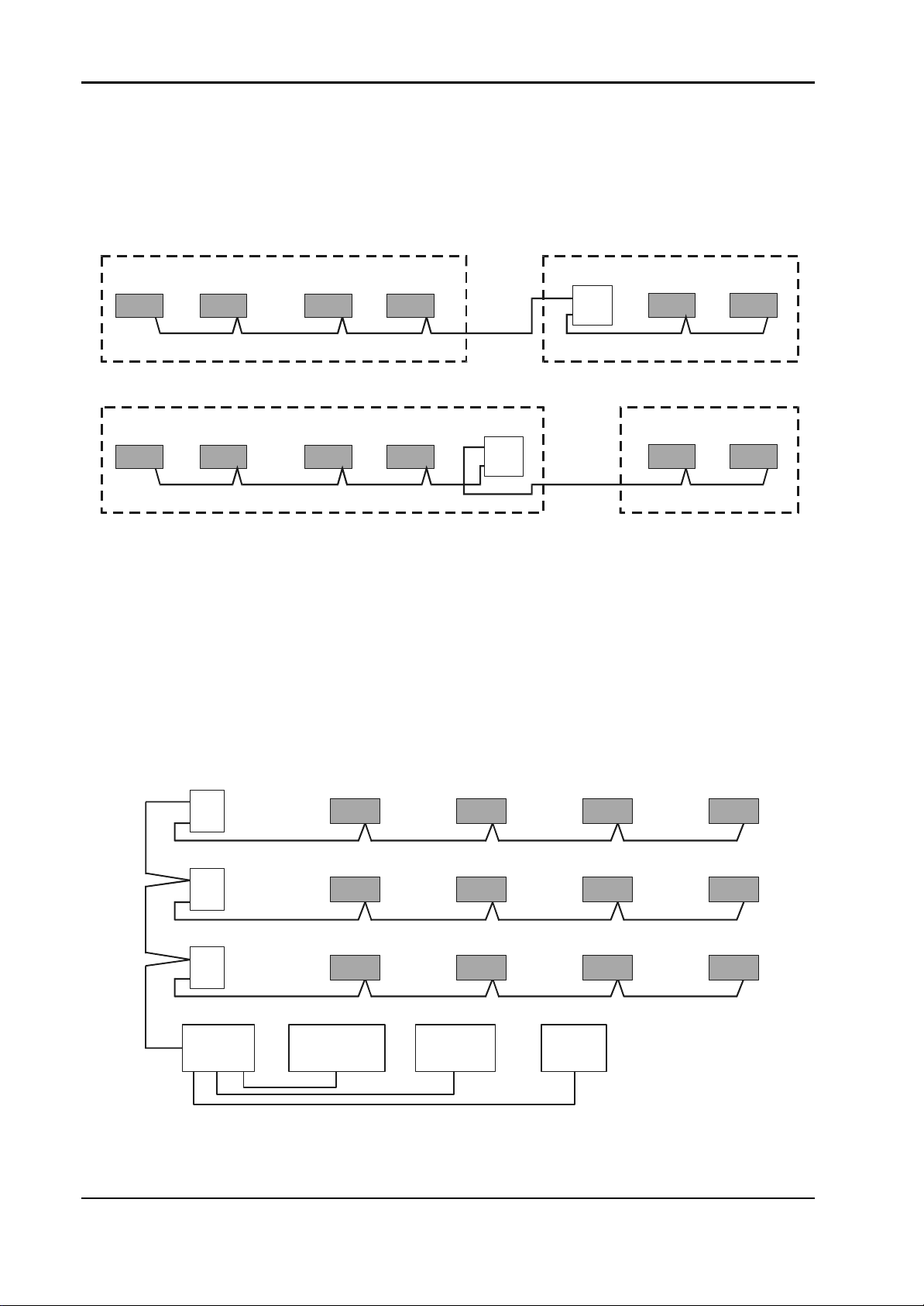
Installation Instructions for Innotech Genesis Systems
S
A-4.1.2. Linking Networks in Different Locations. When linking networks in
different buildings, or when linking modules supplied from different switchboards, isolation
must be provided to eliminate earth loops. Use a GENII RPTR Repeater Module to isolate
the networks (Figure A-3). Note that the cable going to the more remote zone is alway s
connected to Port 2 of the Repeater Module.
Zone BZone A
Repeater
2
1
See NoteSee Note
Zone A Zone B
Repeater
2
1
See Note
Note: Maximum Cable Length = 1000 Metres
Figure A-3. Linking Networks in Different Locations.
See Note
A-4.1.3. Multi-Network Arrangement. Figure A-4 shows a multi-network
arrangement consisting, effectively, of four separate networks. Each is wired in a bus
topology and each could be up to 1000 metres long. The networks are linked by the
electronics in the Repeater Modules. The GENII MPI Modem and Printer Interface does
not need to be an isolated version but it should be noted that the Comms cable connecting
Ports 2 of the Repeater Module will be earthed through the MPI via the PC and the printer.
The correct port of the Repeater Modules must be used to maintain the integrity of isolation
between sections.
2
Repeater
1
See Note
2
Repeater
1
ee Note
See Note
A-4
2
Repeater
1
See Note
MPI PRINTER MODEM PC
Figure A-4. Multi-Network Arrangement.
Note:
Maximum Cable
Length =
1000 Metres
Edition 011100
Page 86

Installation Instructions for Innotech Genesis Systems
A-4.2. GENESIS COMMS WIRING CONSIDERATIONS. The maximum
number of nodes or devices that can be connected on one section of Comms cable is 32. This
limit is set by the characteristics of the RS485 ICs.
The maximum length of Comms cable is 1000 metres. This is determined by the
characteristics of the RS485 ICs and by the characteristics of the cable. In practice, the
maximum length of cable is determined by the quality of the signals. The signal will be
degraded by using cable which does not meet the RS485 cable specification and by installing
the cable in locations where it is subject to interference from other cables and equipment. In
severe cases, it may not be possible to have 32 nodes on one section of cable.
A node is any Genesis product with an RS485 connection. These devices are listed in
Paragraph A-2.
To increase the total number of nodes on a system, a GENII RPTR Repeater Module must be
used (Figure A-5). The two ports on a Repeater Module reside on different sections of the
system and each section can have up to the maximum of 32 nodes. With one repeater, a total
of 62 nodes can be connected on the system. A repeater can be connected at any point on the
network providing bus topology is maintained.
1234- - - 29 30 31 32
Port 2 of the Repeater is one of the 32 nodes on this network
1 234- - - 29 30 31 32
1 234- - - -29 30 31 32
2
1
Port 1 of the Repeater is one of the 32 nodes on this network
Figure A-5. Network Nodes Considerations.
A-4.2.1. Genesis Comms Wiring Connections. Figure A-6 illustrates the
arrangements for connecting the data conductors and screen for the Comms cable to
Genesis products.
It is most important that the two conductors of a twisted pair be correctly identified. Take
extra care with cable that has two twisted pairs with only an overall screen. If a conductor
from one twisted pair is “paired” with a conductor from the other twisted pair, the two data
streams will interfere with each other. This may cause complete failure of the RS485
communications.
Edition 011100
A-5
Page 87

Installation Instructions for Innotech Genesis Systems
END CONNECTIONS LOOPING CONNECTIONS
Screen Connected to Terminal
89 90 91 92 9389 90 91 92 93 89 90 91 92 93
89 90 91 92 9389 90 91 92 93 89 90 91 92 93
Screen Isolated From Terminal
89 90 91
92 93 94
89 90 91
92 93 94
Genesis II only
Alternative Terminal
Screen Connected
Figure A-6. Genesis Comms Wiring Connections.
Screens Isolated and Joined Externally
89 90 91 92 93
Single Twisted Pair. Screens
Isolated and Joined Externally
A-6
Edition 011100
Page 88

Installation Instructions for Innotech Genesis Systems
A-4.2.2. Genesis I Connections. The Common connection provided by the tracks
on the printed circuit board permanently links the following points:
• Terminal 2 (the Zero Volts of the AC supply)
• Terminals 19 and 20 (the connections for the screens of the analogue inputs)
• Terminal 91 (the connection for the screen of the Comms cable)
• The shell and Pin 5 of the DB9 connector for RS232.
If the screen of the Comms cable is connected into Terminal 91, the screen will be earthed
via the earth connection on Terminal 2. To isolate the screen at a Genesis I Digital
Controller, the screen must not be connected to Terminal 91. To maintain the continuity of
the screen, it has to be joined externally from the Genesis I Digital Controller. Refer to
Figure A-7.
Internal Connection to
Terminal 91 is Fixed &
1 2 19 20
Screen
Terminals 2, 19 & 20
(Screen), 91 & Pin 5
of RS232 are Joined
InsideThe Digital
Controller.
89 90 9192 93
Cannot be Opened.
END CONNECTION,
SCREEN CONNECTED
8990919293 8990919293 8990919293
LOOPING CONNECTION, SCREEN ISOLATED
8990919293
LOOPING CONNECTION,
SCREEN CONNECTED
8990919293
EQUIVALENT CIRCUIT
8990919293
Screen Continuity Maintained
by Joining at Terminal 91
8990919293
Screen Isolated From
Digital Controller Ground
by NOT Connecting at
Terminal 91
Edition 011100
Figure A-7. Genesis I Connections.
A-7
Page 89

Installation Instructions for Innotech Genesis Systems
A-4.2.3. Genesis II Connections. The Common connection provided by the tracks
on the printed circuit board permanently link the following points:
• Terminal 2 (the Zero Volts of the AC supply),
• Terminals 19 and 20 (the connections for the screens of the analogue inputs),
• The shell and Pin 5 of the DB9 connector for RS232.
Terminal 91 (the connection for the screen of the Comms cable) is not permanently
connected to Common of the Digital Controller. It can be linked to Common by two shunts
as shown in Figure A-8. These shunts are located on the bottom printed circuit board under
the edge of the top board. On Genesis II Digital Controllers, the screen(s) of the Comms
cable(s) can always be connected or joined in Terminal 91 because it can be isolated from
the Common of the Digital Controller by removing the two shunts. To check that the
screens are isolated, only the two outer shunts on each side should be fitted. The alternative
terminal layout can be found on older versions of the printed circuit board. The terminal
numbering is the same.
12
Terminals 2, 19 & 20
(Screen), 95 & Pin 9
of RS232 are Joined
InsideThe Digital
Controller.
If Shunt Links 3 or 5 are Fitted, Terminal 91 is connected to Terminal 2 and Screen.
NOTE: ON GENESIS II ALW AYS CONNECT THE SCREEN(S) TO TERMINAL 91
AND USE SHUNT LINKS 3 & 5 TO CONNECT OR ISOLATE THE SCREEN.
END CONNECTION
8990919293 8990919293 8990919293
LOOPING CONNECTION
19 20
Screen
89 90 9192 93
Terminal 91 Screen Connection.
LOOPING CONNECTION
8990919293
Shunt
Links
EQUIVALENT CIRCUIT
8990919293
Screen Continuity Maintained
by Joining at Terminal 91
89 90 91
929394
A-8
Alternative Terminal Layout.
When links are fitted,
Terminals 91 and 94 are Internally
Connected to Terminal 2 & Screen
(Terminals 19 & 20).
Figure A-8. Genesis II Connections.
Edition 011100
Page 90

Installation Instructions for Innotech Genesis Systems
A-4.2.4. GENII POLY SWITCH Board. The GENII POLY SWITCH RS485
Protection Plug board can only be used on Genesis II Digital Controllers. The POLY
SWITCH board does not provide fully isolated data lines. It isolates the screen of the
Comms cables from the Common on the Digital Controller.
The POLY SWITCH board provides a level of protection against some types of overvoltage. It protects the RS485 ICs if 24Vac is applied to the Comms Terminals 89 to 93.
To fit a POLY SWITCH board (See Figure A-9):
a. Ensure that the power to all the connections to the Digital Controller is turned off.
b. Remove all shunts from the dual 14-way pin strip on the bottom printed circuit board.
c. Turn the POLY SWITCH Board so that all the components and the socket are facing
to the bottom printed circuit board.
d. Fit the POLY SWITCH Board onto the 14-way pin strip, making sure that the pin
strip and the socket are properly aligned.
e. Do not remove the two shunt links from the other pin strips on the bottom printed
circuit board.
NOTE
The screen links are open on a POLY SWITCH board.
Turn the Poly-Switch Board over so components face bottom board
and socket is toward bottom edge of bottom board. Fit socket onto strip.
Edition 011100
SOCKET
Pin Strip
BOTTOM EDGE OF BOTTOM BOARD
Figure A-9. Genesis II POLY SWITCH Board.
A-9
Page 91

Installation Instructions for Innotech Genesis Systems
A-4.2.5. GENII 485I Isolated RS485 Comms Card. The GENII 485I Isolated
RS485 Comms card can only be used on Genesis II Digital Controllers. It provides
galvanic isolation of the data lines of both the Net Comms and the Global Points and the
screen connection at Terminal 91. To fit a GENII 485I card (See Figure A-10):
a. Ensure that the power to all Digital Controller connections is turned off.
b. Remove the top printed circuit board (six screws).
c. Remove all shunt links from the dual 14-way pin strip and the two shunt links from
the seven- and two-way pin strips on the bottom printed circuit board.
d. Turn the GENII 485I card over so that all the components and sockets are facing the
bottom printed circuit board.
e. Fit the GENII 485I card onto the two-way pin strip, then onto the seven- way vertical
pin strip and then onto the lower seven pins of the dual 14-way pin strip.
f. Refit the top printed circuit board of the Digital Controller.
g. Check that all the pins are in the correct position in all the sockets on the GENII 485I
GENESIS II GEN485I BOARD
GENESIS II GEN485I BOARD
GENESIS II GEN485I BOARD
GENESIS II GEN485I BOARD
These are the Pin Stripsthat must connect to theGEN485I Board.
These are the Pin Stripsthat must connect to theGEN485I Board.
These are the Pin Stripsthat must connect to theGEN485I Board.
These are the Pin Stripsthat must connect to theGEN485I Board.
card.
GENII 485I CARD
A-10
These are the Pin Strips
that must connect to the
GENII 485I Card.
Figure A-10. GENII 485I Isolated RS485 Comms Card.
Edition 011100
Page 92

Installation Instructions for Innotech Genesis Systems
A-4.2.6. GENII RPTR Repeater Module. The Repeater Module (Figure A-11)
can be used with both the Genesis I and Genesis II Digital Controllers. The repeater’s
function is to rebuild each data byte before re-transmitting it.
There are two earth connections on the Repeater Module. The e lectrical earth must be
connected at the E Terminal as it provides a creepage barrier for the mains voltage
connection at the L and N Terminals. The earth (E) associated with the 240Vac supply also
earths the data rebuilding circuitry, which is connected with Port 1. Port 1 should always be
connected to the local devices (the devices that share the same supply and electrical earth).
The other EARTH is for the over-voltage-limiting device connected to Port 2. This device
limits the Port 1 screen voltage above earth to 36 Volts.
Comms. Cable(s) from remote
equipment must be connected
to Terminal Group 2. Screen is
always connected.
Connect to a solid earth
with shortest wire possible
Comms. Cable(s) from local
equipment must be connected
to Terminal Group 1. Screen
can be connected to Port 1
of Repeater if not connected
to earth at another device.
If looping Comms. Cable
through isolated Port 2 of
Repeater, always connect
both screens to the middle
terminal.
EARTH
EARTH
Isolated
From
Internal
2
Circuit
1
Connected To
Internal Circuit
Isolated
From
Internal
2
Circuit
L
N
E
L
N
E
Connect to a solid earth
with shortest wire possible
If Comms. Cable(s) from local
equipment is earthed at another
device, cable screen must not
be connected to Port 1 of
the Repeater.
Figure A-11. GENII RPTR Repeater Module Connections.
Edition 011100
1
Connected To
Internal Circuit
A-11
Page 93

Installation Instructions for Innotech Genesis Systems
WARNING
IF THE EARTH TERMINAL IS NOT CONNECTED TO THE
ELECTRICAL EARTH, THE CABLE CONNECTED T O PORT 2
CAN REACH DANGEROUSLY HIGH VOLTAGES.
Port 2 should be connected to the remote devices - the devices supplied from a different
switchboard.
If the Comms cable connection to Port 1 is an end connection and the Repeater Module is
not the earth point for the screen, the screen of the Comms cable must not be connected to
the terminal. If the Comms cable is looped through Port 1 and the repeater is not the earth
point for the screen, the screens of the two Comms cables will have to be joined but not
connected into the terminal.
Because Port 2 is isolated, the screen(s) of the Comms cable(s) can always be joined in the
terminal.
A-4.2.7. GENII MPI Modem and Printer Interface. The GENII MPI Modem
and Printer Interface can be used with both the Genesis I and Genesis II Digital Controllers.
The MPI is supplied with a double insulated plug pack, which isolates the MPI power
supply from the electrical earth. But, when a printer or PC is connected to the MPI, it will
be connected to the electrical earth via the printer and/or PC cables. See Figure A-12
The Comms is connected to the MPI via the RJ11 socket on the rear of the MPI. The top
portion of Figure A-12 shows the socket connections and the cable as supplied. The
standard order for conductor colours is shown, but they may change and, therefore, should
always be checked before connecting.
To isolate the screen of the Comms cabling from electrical earth at a non-isolated MPI, do
not connect the two GND conductors of the flat MPI cable to the screen(s) of the Comms
cables at the wall connection. This is not an isolated connection for the data conductors.
To provide isolation for the data conductors, an MPI fitted with RS485 isolation ICs must
be used. The two GND conductors should be connected to the screen(s) of the Comms
cable when an isolated MPI is used. Connecting the screen(s) of the Comms cable(s)
completes the internal over-voltage protection on the MPI data connections.
A-12
Edition 011100
Page 94

Installation Instructions for Innotech Genesis Systems
NOTE
On some units, wire colours
G+
G-
N-
N+
Gnd
Gnd
White
Black
Red
Green
Yellow
may be different than as
Blue
shown here.
N- (blue)
N+ (yellow)
Gnd (green)
Gnd (red)
G- (black)
Socket on MPI viewed
from rear of MPI
Plug and Cable viewed as
plugged into rear of MPI
G+ (white)
COMMS CABLE CONNECTION ON MPI
A non-isolated MPI has the three DB connector shells and the pins shown connected
to COMMON. When a Printer or PC is connected, the RS485 Comms is earthed.
PC
MODEM
PRINTER
An isolated MPI has the three DB connector shells and the pins shown connected
to COMMON. When a Printer or PC is connected, the RS485 Comms are NOT earthed.
PC
MODEM
PRINTER
Figure A-12. GENII MPI Modem and Printer Interface.
A-4.2.8. Genesis I Non-Isolated Comms. Because Genesis I Digital Controllers
do not have links between the RS485 ICs and the Comms terminals, the Comms terminals
are permanently connected to the Digital Controller Common and to Terminal 2.
Therefore, the screen(s) of the Comms cable(s) must be connected to Terminal 91 of only
one Digital Controller, as shown in the Figure A-13.
At looping connections the screens must be joined externally as shown in Figure A-13. The
screen must not be connected to the terminal at an end connection that is not the earthing
point for the screens.
For Digital Controllers supplied from one switchboard or mounted in one control panel, the
screen is earthed at one Digital Controller only.
Edition 011100
A-13
Page 95

Installation Instructions for Innotech Genesis Systems
g
End
Screen is earthed
to Terminal 91
only at this Di
Controller.
ital
Connection
Looping
Connection
1 2
SEE NOTE
SEE NOTE
Screen
Screen1 2
NOTE
Connection to
Terminal 91 is
fixed and cannot
be opened.
Figure A-13. Genesis I Non-Isolated Comms.
Looping
Connection
End
Connection
Screen1 2
SEE NOTE
Screen1 2
SEE NOTE
A-4.2.9. Genesis II Non-Isolated Comms. If all the devices on the Genesis II
network are supplied from the same switchboard, they will be connected to the same
electrical earth. Therefore, the Common connection of these Digital Controllers should be
at the same voltage and within the rated voltage of the RS485 ICs.
A-14
Edition 011100
Page 96

Installation Instructions for Innotech Genesis Systems
The Genesis II has links that allow the screen connection of the RS485 Comms cable to be
disconnected from the Common of the Digital Controller. Therefore, the screen(s) of the
RS485 cable(s) can be joined in the Comms terminals of the Digital Controllers and still be
isolated if only the four outer links are fitted. This is shown in Figure A-14 with the screen
earthed at Digital Controller Number 2 because it has six links fitted.
Any of the Digital Controllers can be selected as the one that is used to earth the screen, but
it is best to choose the Digital Controller that will provide the most effective earth.
End
89 9 0 91 92 93
Connection
1 2
Screen
Only four outer
links fitted.
Screen is not
earthed.
Connect Screen
Looping
Connection
Looping
Connection
End
Connection
89 9 0 91 92 93
89 9 0 91 92 93
89 9 0 91 92 93
1 2
Screen
Six outer links
fitted. Screen is
earthed via
Terminal 2.
Connect Screen
Screen1 2
Only four outer
links fitted.
Screen is not
earthed.
Connect Screen
Screen1 2
Only four outer
links fitted.
Screen is not
earthed.
Edition 011100
Connect Screen
Figure A-14. Genesis II Non-Isolated Comms.
A-15
Page 97
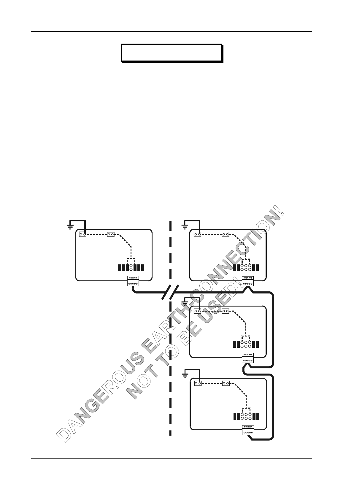
Installation Instructions for Innotech Genesis Systems
WARNING
PARAGRAPHS A-4.2.9.1 AND A-4.2.9.2, BELOW, AND THEIR
REFERENCED FIGURES DESCRIBE IMPROPER EARTHCONNECTION CONDITIONS THAT COULD LEAD TO SEVERE
ELECTRICAL SHOCK OR DAMAGE TO EQUIPMENT. READ
AND UNDERSTAND THESE PARAGRAPHS THOROUGHLY
BEFORE MAKING ANY COMMS CONNECTIONS.
A-4.2.9.1. Hazardous Earth-Connections. When the Digital Controllers are
supplied and earthed from two different switchboards, a hazardous situation can be
created. One earth connection is at the local switchboard and the second earth
connection is by way of the screen of the Comms cable (Figure A-15). In the event of a
fault, there could be full supply voltage difference between the two earth connections.
This can destroy the RS485 ICs and anyone touching the screen can receive a severe
electric shock. The RS485 ICs in the three Digital Controllers in Control Panel No.2
will be damaged if the voltage difference exceeds the ratings of the ICs. Because of this
hazard, this arrangement of connection should not be used.
Switchboard or
Control Panel No. 1
1 2
Six outer links
fitted. Screen is
Connect Screen
Screen
earthed via
Terminal 2.
Switchboard or
Control Panel No. 2
Screen1 2
Only four outer
links fitted.
Screen is not
earthed.
Connect Screen
1 2
Only four outer
Screen is not
Connect Screen
Screen
links fitted.
earthed.
A-16
1 2
Only four outer
links fitted.
Screen is not
Connect Screen
Screen
earthed.
Figure A-15. Hazardous Connection Example, Circuit 1.
Edition 011100
Page 98

Installation Instructions for Innotech Genesis Systems
Figure A-16 shows a wiring arrangement that is slightly better. The earthing point for
the screen is at the first Digital Controller in a group located together and supplied from
one switchboard. It gives better protection to the greater number of Digital Controllers.
This arrangement does not remove the hazard that the screen voltage at point A in the
figure is not at the earth voltage of that Digital Controller. Nor does it remove the
possibility of damage to the RS485 ICs if the voltage difference exceeds the voltage
ratings of the IC.
If the three Digital Controllers in Control Panel No. 2 are solidly bonded together and to
earth, then it is possible that only the RS485 IC in the Digital Controller in Control Panel
No. 1 will be damaged.
Switchboard or
Control Panel No. 1
Screen1 2
Only four outer
links fitted.
Screen is not
earthed.
Connect Screen
A
Switchboard or
Control Panel No. 2
1 2
Six outer links
fitted. Screen is
earthed via
Connect Screen
1 2
Only four outer
links fitted.
Screen is not
Connect Screen
Screen
Terminal 2.
Screen
earthed.
Edition 011100
1 2
Only four outer
links fitted.
Screen is not
Connect Screen
Screen
earthed.
Figure A-16. Hazardous Connection Example, Circuit 2.
A-17
Page 99

Installation Instructions for Innotech Genesis Systems
A-4.2.9.2. Use of GENII POLY SWITCH Boards. The GENII Poly Switch
Boards provide some protection from over-voltage and voltage spikes. To achieve the
maximum benefit, Poly Switches should be fitted to all Digital Controllers in a network.
Fitting Poly Switches to all Digital Controllers results in the screen(s) being unearthed
because the Poly Switches do not link the screen Terminal 91 to the Common and
Terminal 2. An external earth must be fitted to Terminal 91 of the Digital Controller
where the screens are to be earthed.
When the Digital Controllers are supplied from two different switchboards (Figure A-
17), the hazardous situation is still a possibility in the event of a fault. The Poly
Switches may protect the RS485 ICs providing that the voltage differences are not
excessive. Fitting the screen earth at the single Digital Controller is not the preferred
location.
Switchboard or
Control Panel No. 1
1 2
Screen
Poly-Switch
board only links
data. Screen
isolated.
Connect Screen
Switchboard or
Control Panel No. 2
1 2
Screen
Poly-Switch
board only links
data. Screen
isolated.
Connect Screen
1 2
Screen
Poly-Switch
board only links
data. Screen
isolated.
A-18
Connect Screen
Screen1 2
Only four outer
links fitted.
Screen is not
earthed.
Connect Screen
Figure A-17. Use of GENII Poly Switch Boards, Circuit 1.
Edition 011100
Page 100

Installation Instructions for Innotech Genesis Systems
Figure A-18 shows the preferred connection point for the screen earth. Fitting it on the
screen terminal of one of a group of Digital Controllers gives optimum protection to the
greater number of Digital Controllers. The earthing point for the screen is at the first
Digital Controller in a group located together and supplied from one switchboard. This
preferred connection point does not remove the hazard that the screen voltage at point A
of Figure A-18 is not at earth voltage.
Switchboard or
Control Panel No. 1
1 2
Screen
Poly-Switch
board only links
data. Screen
isolated.
Connect Screen
A
Switchboard or
Control Panel No. 2
1 2
Screen
Poly-Switch
board only links
data. Screen
isolated.
Connect Screen
Screen1 2
Poly-Switch
board only links
data. Screen
isolated.
Connect Screen
Screen1 2
Only four outer
links fitted.
Screen is not
earthed.
Connect Screen
Figure A-18. Use of GENII Poly Switch Boards, Circuit 2
WARNING
ALTHOUGH AN IMPROVEMENT OVER PREVIOUS EARTHCONNECTION METHODS, THE CIRCUITS DESCRIBED IN
PARAGRAPH A-4.2.10 STILL DO NOT REMOVE THE
ELECTRICAL SHOCK HAZARD DESCRIBED IN THE
PREVIOUS PARAGRAPH.
Edition 011100
A-19
 Loading...