

InnoMedia MTA8328 Administrative Manual

March, 2017
InnoMedia MTA8328
Administrative Guide
INNOMEDIA CONFIDENTIAL
This document contains proprietary information of InnoMedia Inc., and its receipt or possession does not
convey any rights to reproduce, disclose its contents, or to manufacture, use or sell anything it may describe.
It may not be reproduced, disclosed or used without specific written authorization of InnoMedia Inc.

InnoMedia 8328-1 Administrative Guide
Page 2
Copyright © 2017 InnoMedia. All rights reserved.
Table of Contents
1
Introduction ......................................................................................................................................... 7
1.1 Product Overview ................................................................................................................................... 7
1.2 Package Contents ................................................................................................................................... 7
1.2.1 MTA8328-1 Models and Packaging.............................................................................................. 7
1.3 MTA8328 Out of the Box Setup ............................................................................................................. 8
1.3.1 MTA8328-1N or MTA8328-1W/V Setup ....................................................................................... 8
2
Home –Device States ...................................................................................................................... 10
3
Network .......................................................................................................................................... 13
3.1 IP Address Configuration for MTA8328 ................................................................................................ 13
3.1.1 Ethernet or WiFi IP Address Setting ............................................................................................ 13
3.1.2 Host and DNS Servers ................................................................................................................. 14
3.1.3 Master DNS ................................................................................................................................. 14
3.1.4 TOS Setting.................................................................................................................................. 15
4
Telephony .......................................................................................................................................... 16
4.1 Profile Config ........................................................................................................................................ 16
4.1.1 SIP Server Setting ........................................................................................................................ 16
4.1.2 Security Setting ........................................................................................................................... 19
4.1.3 Codec Setting .............................................................................................................................. 20
4.1.4 SIP Timer Setting ......................................................................................................................... 21
4.1.5 DigitMap Setting ......................................................................................................................... 22
4.1.6 Feature and Service Code Setting ............................................................................................... 26
4.1.7 Fax Setting .................................................................................................................................. 28
4.1.8 Call Report Setting ...................................................................................................................... 29
4.2 Port Config ............................................................................................................................................ 29
4.2.1 SIP Account Setting ..................................................................................................................... 30
4.2.2 Features Setting .......................................................................................................................... 30
4.2.3 Line Setting ................................................................................................................................. 31
4.2.4 Speed Dial ................................................................................................................................... 32
4.2.5 IMS related SIP settings .............................................................................................................. 32
4.3 Telephony Region and Misc Setting ..................................................................................................... 33
4.3.1 Media Port Setting ...................................................................................................................... 33
4.3.2 Tone Cadence Setting ................................................................................................................. 34
4.3.3 Ring Cadence Setting .................................................................................................................. 35
4.4 Line Diagnostics .................................................................................................................................... 36
4.4.1 GR909 Tests: triggered from the WEB Administrative Console .................................................. 36
4.4.2 GR909 Tests: triggered from SIP NOTIFY Message ..................................................................... 37
4.5 Wireless Location Optimizer ................................................................................................................ 38

InnoMedia 8328-1 Administrative Guide
Page 3
Copyright © 2017 InnoMedia. All rights reserved.
5 System .............................................................................................................................................. 39
5.1 Account Settings ................................................................................................................................... 39
5.1.1 Administrator Account Setting ................................................................................................... 39
5.1.2 End User Account Setting ........................................................................................................... 39
5.2 Page Permission ................................................................................................................................... 40
5.3 Firmware Upload .................................................................................................................................. 40
5.4 Reboot .................................................................................................................................................. 41
5.5 Restore To Factory ............................................................................................................................... 41
5.6 Provisioning Setting .............................................................................................................................. 42
5.6.1 Provision Server Setting .............................................................................................................. 42
5.7 EMS Setting .......................................................................................................................................... 44
5.7.1 EMS Server .................................................................................................................................. 44
5.8 Trace Log .............................................................................................................................................. 46
5.8.1 Trace Log Setting......................................................................................................................... 46
5.9 System Time ......................................................................................................................................... 47
5.9.1 Time Setting ................................................................................................................................ 47
5.10 Language .............................................................................................................................................. 49
5.11 Uplink Connection ................................................................................................................................ 49
5.12 Certificate & Key ................................................................................................................................... 50
5.13 Config File ............................................................................................................................................. 50
5.14 SNMP Setting ........................................................................................................................................ 51
5.15 Remote Access ..................................................................................................................................... 52
5.15.1 Remote Access Setting ................................................................................................................ 52
6 CLI Command references ............................................................................................................................. 53
7 Appendix A LED States ............................................................................................................................... 54
7.1 Model MTA8328-1N ............................................................................................................................. 54
8 Appendix B The use of encryption key methods ....................................................................................... 55
8.1 Inno rc4_102 ........................................................................................................................................ 55
8.2 Openssl command example ................................................................................................................. 55
9 Appendix C Wall Installation of Device ..................................................................................................... 56
10 Appendix D FCC Statement ....................................................................................................................... 57

InnoMedia 8328-1 Administrative Guide
Page 4
Copyright © 2017 InnoMedia. All rights reserved.
Table of Figures
Figure 1. MTA8328-1N Package ............................................................................................................................ 7
Figure 2. MTA8328-1N Front and back panel. ...................................................................................................... 7
Figure 3. Setup the MTA device to connect to the router or network switch ...................................................... 8
Figure 4. Login Screen (Username and Password). The MTA8328-1N screen example. ..............................
10109
Figure 5. Current status of MTA8328-1N.................................................................................................... 111110
Figure 6. Configuring the IP Address on the Ethernet Interface ................................................................. 131312
Figure 7. Configuring the host information on the device ......................................................................... 141413
Figure 8. Configuring the Master DNS Information .................................................................................... 141413
Figure 9. ToS Setting ................................................................................................................................... 151514
Figure 10 Configuring Telephony options ................................................................................................... 161615
Figure 11. SIP Server Settings—SIP Proxy Server ........................................................................................ 161615
Figure 12. SIP Server Settings – SIP Option ................................................................................................. 171716
Figure 13. MTA Security Settings ................................................................................................................ 191918
Figure 14. Codec Setting ............................................................................................................................. 202019
Figure 15. SIP Timer Setting ........................................................................................................................ 212120
Figure 16. DigitMap Setting ........................................................................................................................ 222221
Figure 17. FXS Setting ................................................................................................................................. 252524
Figure 18. Feature and Service Code Setting .............................................................................................. 262625
Figure 19. Fax Setting ................................................................................................................................. 282827
Figure 20. CDR Setting ................................................................................................................................ 292928
Figure 21. Phone port status overview ....................................................................................................... 292928
Figure 22. SIP Account Setting .................................................................................................................... 303029
Figure 23. Call Feature Setting .................................................................................................................... 303029
Figure 24. Line Setting ................................................................................................................................ 313130
Figure 25. Speed Dial .................................................................................................................................. 323231
Figure 26. IMS Settings ............................................................................................................................... 323231
Figure 27. Media Port Setting ..................................................................................................................... 333332
Figure 28. Tone Cadence Setting ................................................................................................................ 343433
Figure 29. Ring Cadence Setting ................................................................................................................. 363635
Figure 30. GR909 Test Line Test ................................................................................................................. 363635
Figure 31. Administrator account setting ................................................................................................... 393937
Figure 32. User Account Setting ................................................................................................................. 393937

InnoMedia 8328-1 Administrative Guide
Page 5
Copyright © 2017 InnoMedia. All rights reserved.
Figure 33. User Page Permission Setting .................................................................................................... 404038
Figure 34. Firmware Upload ....................................................................................................................... 404038
Figure 35. Reboot Dialog ............................................................................................................................ 414139
Figure 36. Restore To Factory Dialog .......................................................................................................... 414139
Figure 37. Provisioning Server Setting ........................................................................................................ 424240
Figure 38. Configuring EMS Server Information ......................................................................................... 444442
Figure 39. Trace Log Setting ....................................................................................................................... 464644
Figure 40. Time Setting ............................................................................................................................... 484846
Figure 41. Language Selection for IVR system ............................................................................................ 494947
Figure 42. Uplink Detection Settings .......................................................................................................... 494947
Figure 43. Certification & Key ..................................................................................................................... 505048
Figure 44. System Config ............................................................................................................................ 505048
Figure 45. SNMP Setting ............................................................................................................................. 515149
Figure 46. Protocol and Port Settings for Remote Access .......................................................................... 525250

InnoMedia 8328-1 Administrative Guide
Page 6
Copyright © 2017 InnoMedia. All rights reserved.
About This Document
This document provides details of the features available on the InnoMedia MTA8328 as well as feature
descriptions and the configurations required.
Revision History
Date
Version
Notes
2016/10/25
V1.0
Based on firmware V1.0.0.19
2016/11/08
V1.1
Based on firmware V1.0.0.23
2016/11/23
V1.1
Based on firmware V1.0.0.27
2017/03/10
V1.2
Based on firmware V1.0.4.4
InnoMedia 8328-1 Administrative Guide
Page 7
Copyright © 2017 InnoMedia. All rights reserved.
1 INTRODUCTION
1.1 Product Overview
The InnoMedia MTA8328 is an integrated device providing telephony service over a broadband network. It
allows the connection of your device to your Home Router through either a wired Ethernet connection or
through WiFi1. This guide will help you to quickly install and configure your unit so that you can start placing
calls right away.
1.2 Package Contents
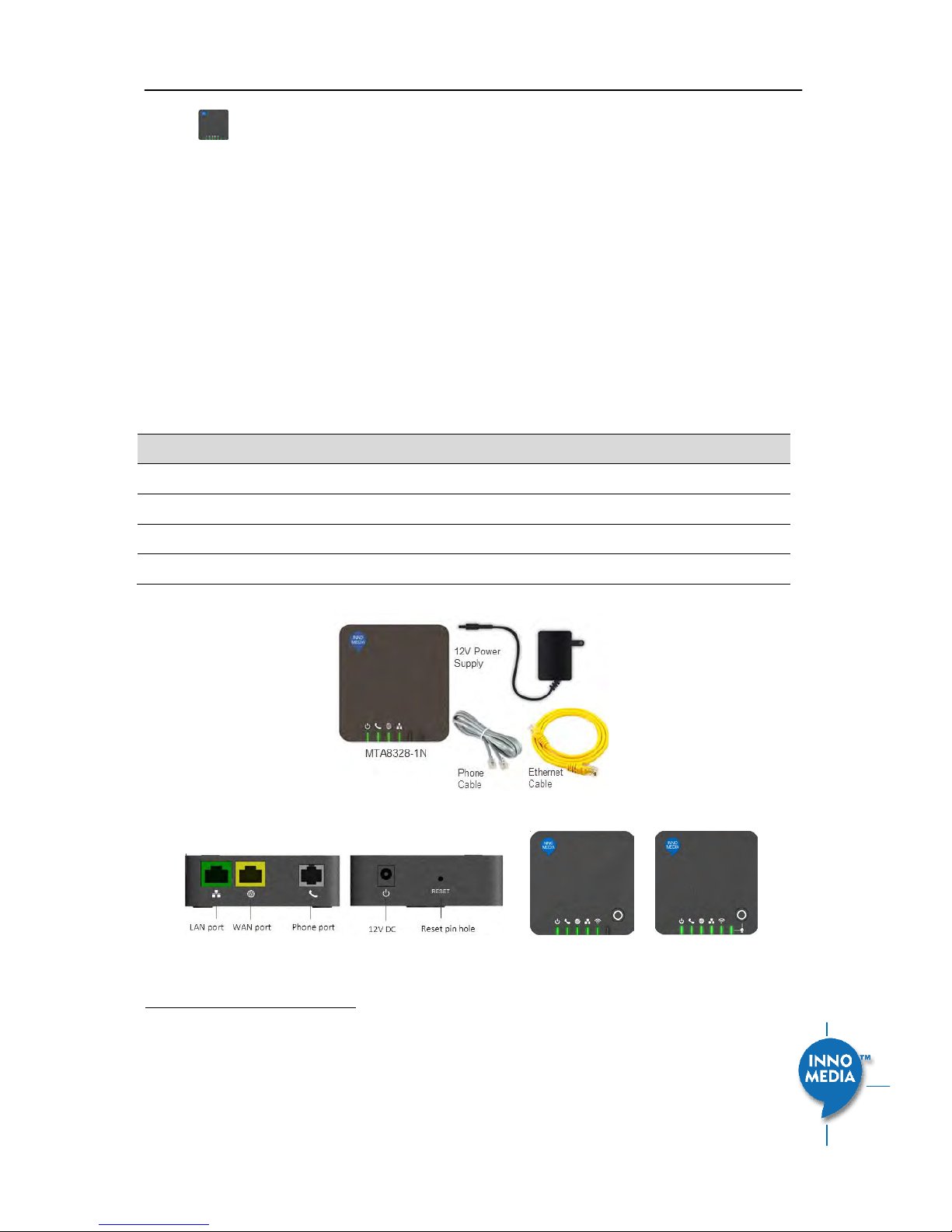
1.2.1 MTA8328-1 Models and Packaging
The MTA 8328-1N supports an Ethernet interface connected to the Home Router or a LAN network.
Item List
Quantity
MTA8328-1N device
1
12V Power Adapter
1
Phone Cable
1
Ethernet Cable
1
Figure 1. MTA8328-1N top view and Packaging for MTA8328-1 Series
Figure 2. MTA8328-1 series Front and back panel, and MTA8328-1W/V Top views.
1
WiFi functionality is supported on certain models only.
InnoMedia 8328-1 Administrative Guide
Page 8
Copyright © 2017 InnoMedia. All rights reserved.
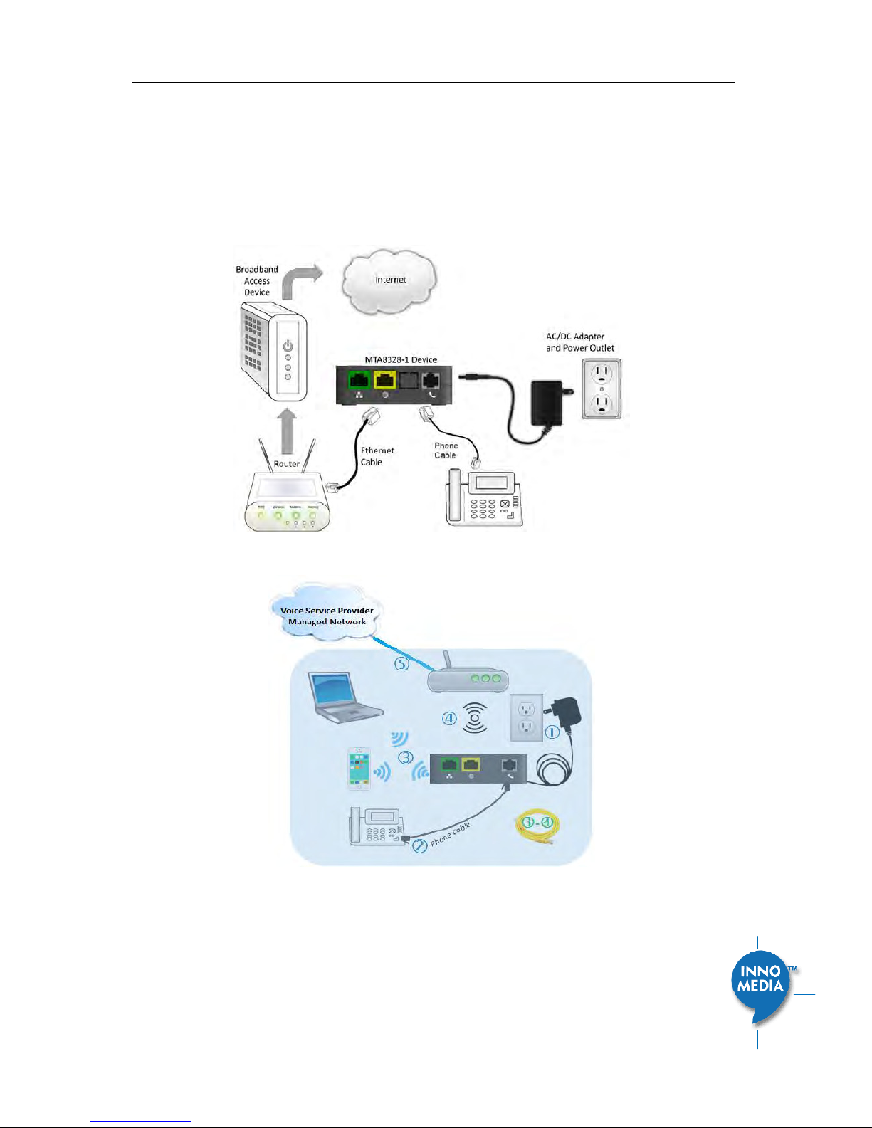
1.3 MTA8328 Out of the Box Setup
1.3.1 MTA8328-1N or MTA8328-1W/V Setup
This section provides a step-by-step guide to install the MTA8328 and setup the system for connecting to a
broadband network. Before starting the Installation, make sure your broadband Internet access device is
powered on and your connection is up (chek ou Iteet seie poides douetatio.
Figure 3. Setup the MTA device to connect to the router or network switch

InnoMedia 8328-1 Administrative Guide
Page 9
Copyright © 2017 InnoMedia. All rights reserved.
1. Plug the supplied power adapter into the MTA8328. The power LED will show steady green.
2. Connect your phone into the PHONE port on the MTA using the supplied Phone Cable.
3. Setup the MTA to connect to your Home Router. Connect the yellow Ethernet cable (supplied) into
the WAN port on the MTA and connect the other end into an available Ethernet port on your router
or LAN network.
4. If you have a device with Wifi, use the Captive Portal method to configure the the Wifi portion of the
device and connect it to you home router.
a. Press the round button on the device for more than 5 secs
b. Use your mobile device o laptop to disoe the ““ID MTA hee the ae
last 4 digits of your device MAC address
c. Connect to that SSID and configure your device with the appropriate pass phrase and
complete the Wifi setup of your device
5. Confirm that the MTA is successfully connected to the router and has acquired an IP address by
checking that the WAN LED shows green for a 100BT connection, or amber for 10BT.
6. Once the MTA connects to the voice service provider network, and completes the registration and
service provision process, you should see a solid green PHONE LED light displayed.
InnoMedia 8328-1 Administrative Guide
Page 10
Copyright © 2017 InnoMedia. All rights reserved.
2 HOME –DEVICE STATES
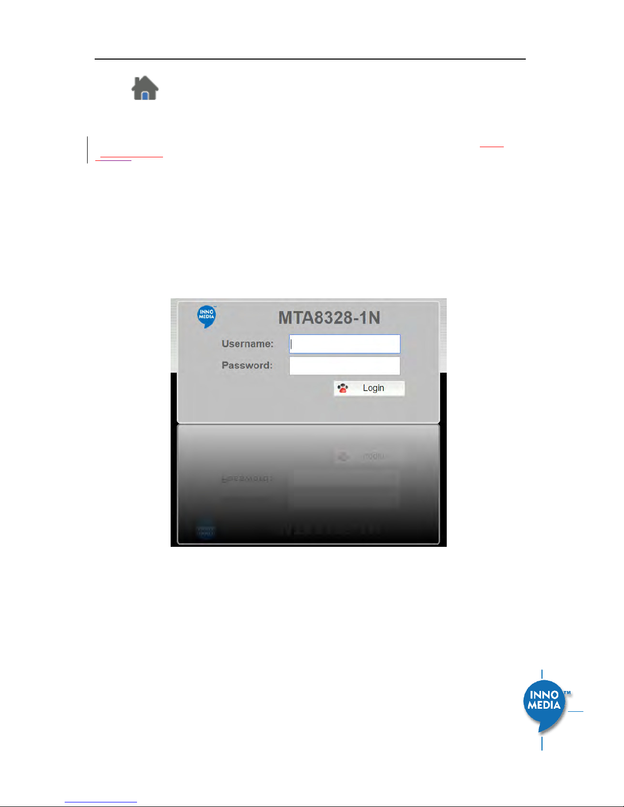
Login Screen
The MTA can be managed via a Web Browser interface. Once the MTA is connected as outlined in
Figure
3Figure 3Figure 3, proceed to access and configure the MTA8328 via a Web Browser from a PC connected to
the same router as the MTA WAN interface, or directly connect to the MTA LAN interface.
Press ***1 on the phone which connects to the MTA and get the IP address of the MTA.
The default Admin Username is: admin
The default Password is: password
The default end user Username is: user
The default Password is: welcome
Note: The default username and password could be different if changed by the service provider.
Figure 4. Login Screen (Username and Password). MTA8328-1N login screen example.
InnoMedia 8328-1 Administrative Guide
Page 11
Copyright © 2017 InnoMedia. All rights reserved.
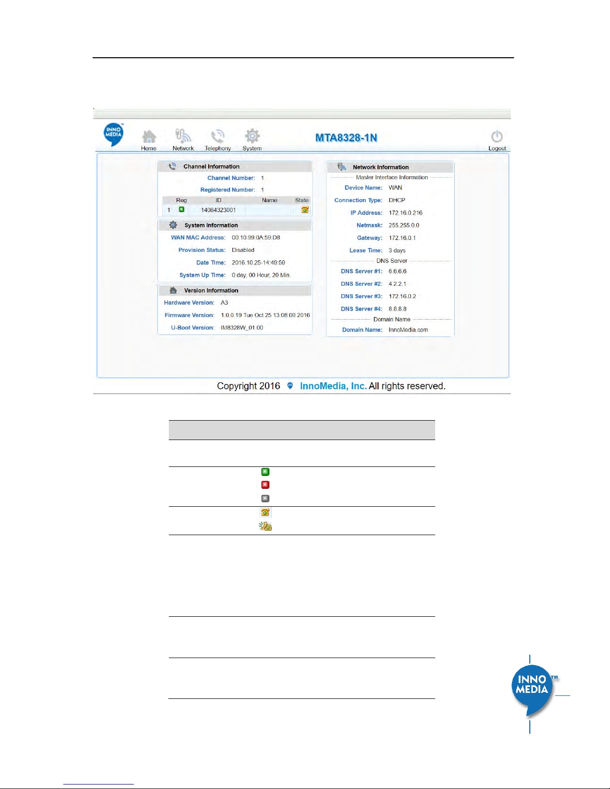
Home Page
The Hoe page displas the deies uet status of MTA8328-1N, as an example.
Figure 5. Current status of MTA8328-1N
Field Name
Description
Channel
Information
Number of phone lines provisioned
Number of SIP accounts provisioned
Reg Status
Successfully REGISTERED with SIP proxy
Not REGISTERED with SIP proxy
Account disabled
State
Phone on hook
Phone off hook
System
Information
MAC address of Ethernet WAN
Provision Status: last provisioning date-
time and status
Date Time: current date and time
System Up Time: up time since last
power up.
Version
Information
Hardware Version
Firmware Version
Boot Loader Version
Network
Information
Master Information: Current active (in
use) network.
DNS Server: all DNS server IP addresses

InnoMedia 8328-1 Administrative Guide
Page 12
Copyright © 2017 InnoMedia. All rights reserved.
configured on the MTA devices. The
priority order of DNS servers (in order of
decreasing priority) used is: Master DNS
server(s) > those obtained from the
DHCP server > user configured DNS
server(s). See section 3.1.3 for details
on Master DNS.
Domain Name: the domain name
obtained from DHCP Option 15 or the
configured value described in section
3.1.2. The value obtained from DHCP
has higher priority than any manually
configured domain name.
InnoMedia 8328-1 Administrative Guide
Page 13
Copyright © 2017 InnoMedia. All rights reserved.
3 NETWORK
The Network pages allow the configuration of the MTA8328 network parameters.
3.1 IP Address Configuration for MTA8328
Configure IP address parameters for this device.
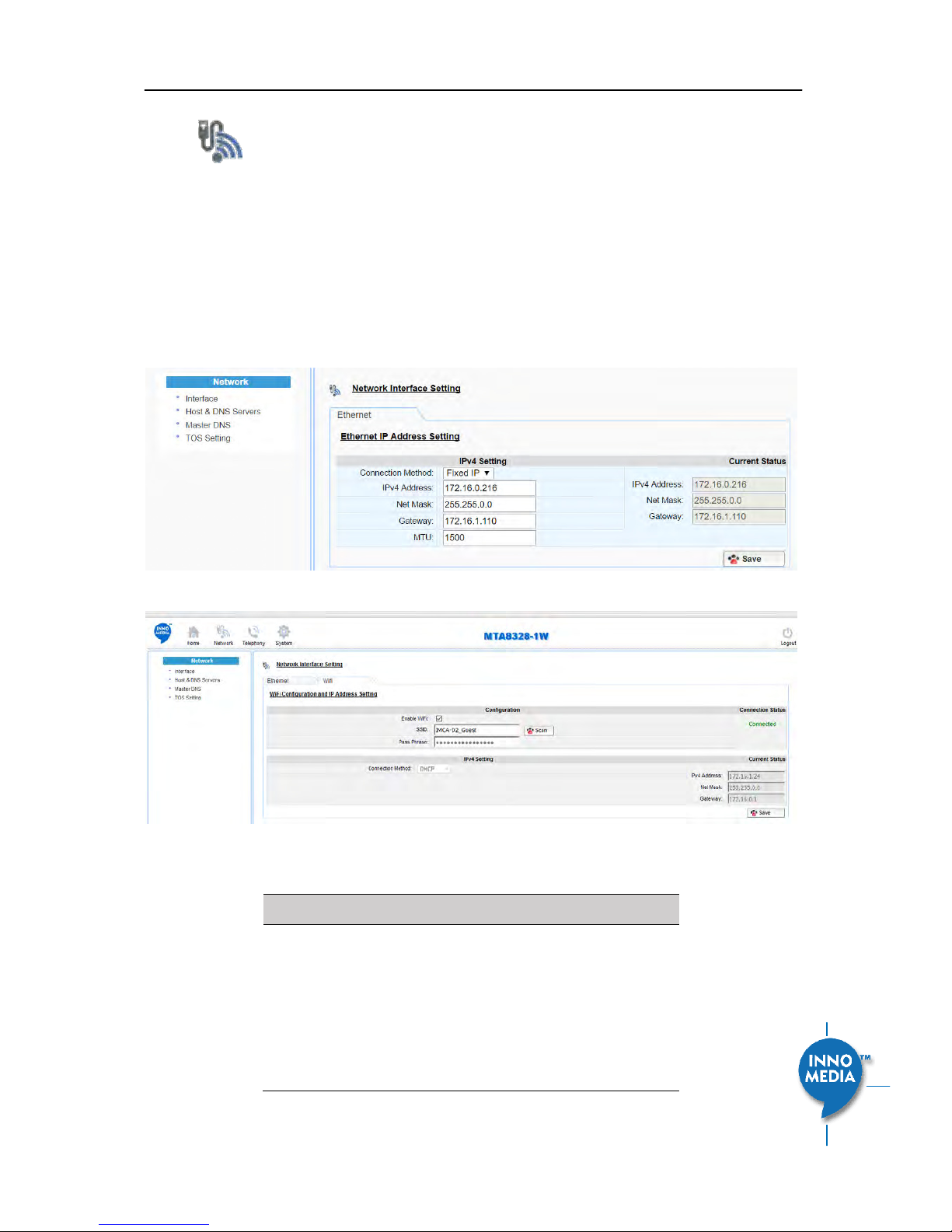
3.1.1 Ethernet or WiFi IP Address Setting
Cofigue the IP IP addess fo the deie. Clik the Interface eu fo the left pael.
Figure 6. Configuring the IP Address on the Ethernet or WifiInterface
Field Name
Description
Connection
Method
DHCP: Automatically acquires IP address
from the Home Router.
Fixed IP: Need to configure the
following parameters according to the
Home Router network settings.
IPv4 IP address | Netmask | Gateway |
MTU (maximum size of a IP packet, in
bytes).
InnoMedia 8328-1 Administrative Guide
Page 14
Copyright © 2017 InnoMedia. All rights reserved.
Note that default value of MTU is 1500,
and its valid value ranges from 150 to
1500. Do not change MTU value unless
necessary.
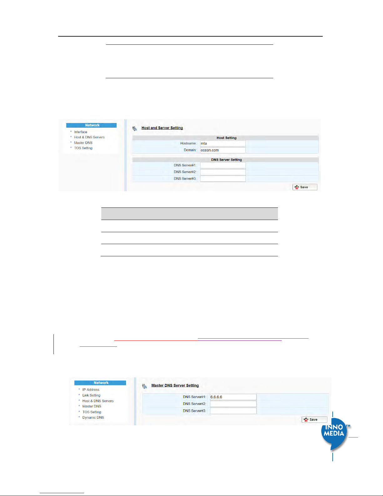
3.1.2 Host and DNS Servers
Configure the host and the DNS server information provided by your network operator.
Figure 7. Configuring the host information on the device
Field Name
Description
Host Name
Configure the host name for the device.
Domain
Configure the domain name for the device.
DNS Server Setting
Allows configuration of up to three DNS servers.
3.1.3 Master DNS
Maste DN“ is the IP addess of the doai ae see speified the telepho seie poide athe
tha the iteet seie poide. If Maste DN“ is onfigured, the MTA gets related DNS services from this
configured server to perform voice communication functions. The MTA acquires DNS server information from
the following servers in the priority shown (in order of decreasing priority).
1. Master DNS
2. DHCP Option (
Ethernet or WiFi IP Address SettingEthernet or WiFi IP Address SettingEthernet IP
Address Setting)
3. Manually configured DNS (see section 3.1.2)
Figure 8. Configuring the Master DNS Information
InnoMedia 8328-1 Administrative Guide
Page 15
Copyright © 2017 InnoMedia. All rights reserved.
Field Name
Description
DNS Server
Configure the DNS server information
specified by the VoIP service provider.
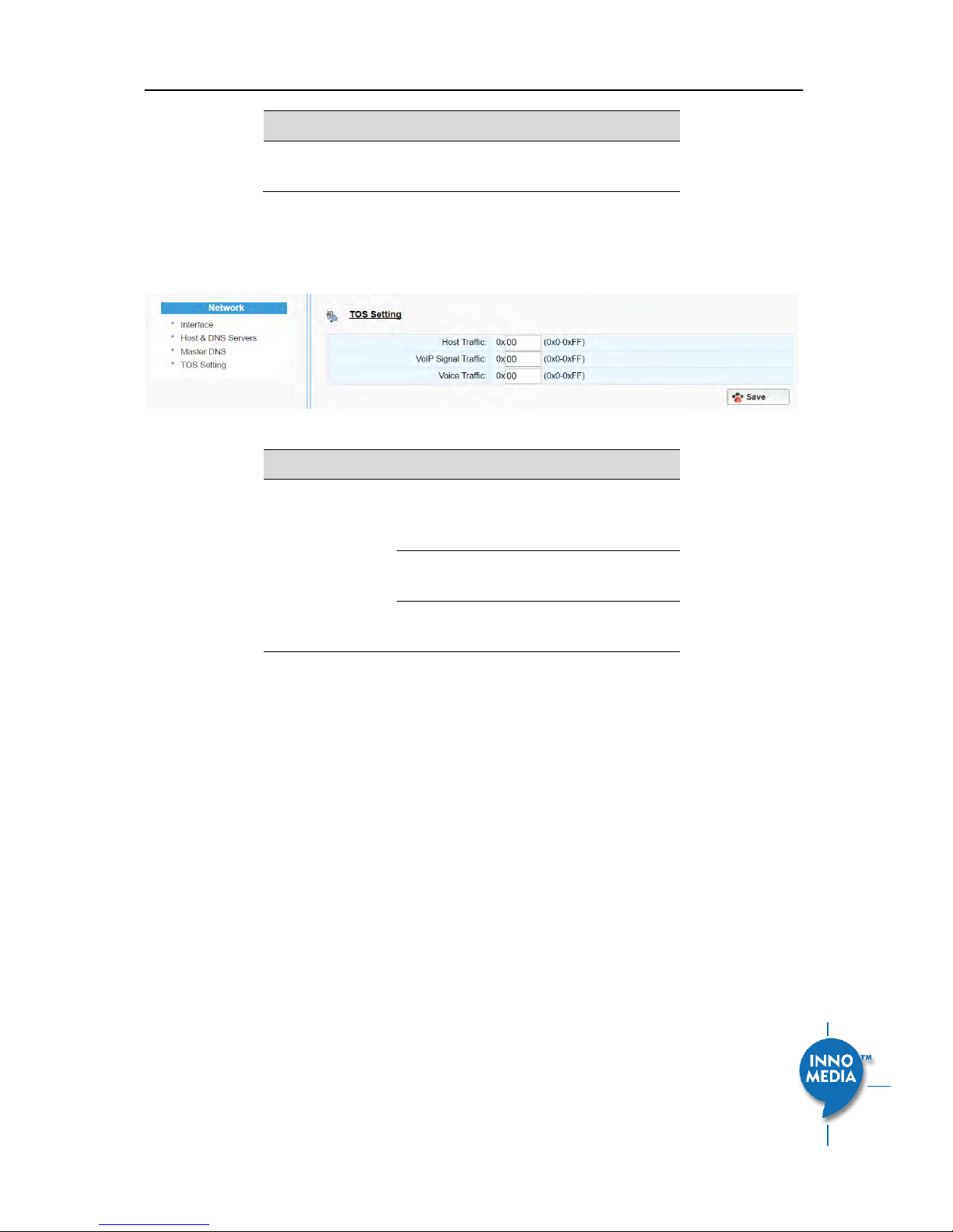
3.1.4 TOS Setting
TOS (Type of Service) is a part of the IPv4 header which is used for precedence, or in other words categorizing
traffic classes. The higher the value of the IP Precedence field, the higher the priority of the IP packet.
Figure 9. ToS Setting
Field Name
Description
TOS Setting
Host Traffic: Use the configured TOS value to
tag data traffic other than SIP or RTP
packets.
VoIP Signal Traffic: Use the configured TOS
value to tag SIP signaling packets.
Voice Traffic: Use the configured TOS value
to tag voice RTP packets.
InnoMedia 8328-1 Administrative Guide
Page 16
Copyright © 2017 InnoMedia. All rights reserved.
4 TELEPHONY
The Telephony section is used to configure SIP Parameters, telephony settings (including regional settings)
and line diagnostics.
Figure 10 Configuring Telephony options
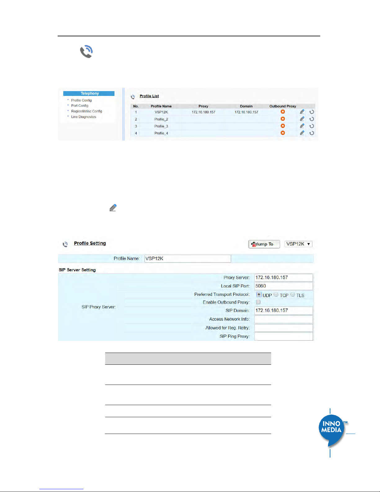
4.1 Profile Config
Profiles include SIP Server/Proxy Settings, Codec Settings, SIP Timer Settings, Digitmap Settings, FXS Settings,
Feature and Service Code Settings, Fax Settings and Regional Settings which are described in the following
sections.
Click on the Edit icon
of a particular profile to display the profile setting screen.
4.1.1 SIP Server Setting
Figure 11. SIP Server Settings—SIP Proxy Server
Field Name
Description
Profile Name
Up to 4 profiles can be created. (The profile
ID corresponds to the No. in the Profile List.)
Proxy Server
The FQDN or IP address of the SIP proxy
server
Local SIP Port
The SIP port used on the MTA
Preferred
If there are no queried NAPTR records
specifying the transport protocols to be
InnoMedia 8328-1 Administrative Guide
Page 17
Copyright © 2017 InnoMedia. All rights reserved.
Transport Protocol
used, the MTA uses this configured setting
to set up proceed VoIP calls setup with the
SIP server.
UDP | TCP | TLS
Enable Outbound
Proxy
If enabled, the MTA uses the value
ofigued i Po “ee as the
outbound proxy server setting.
SIP Domain
The MTA uses this setting to (1) compose
the host part of SIP request URI strings (2)
perform NAPTR/SRV queries.
Access Network
Info
This header is useful in SIP-based networks
that also provide layer 2/layer 3 connectivity
through different access technologies. SIP
User Agents may use this header to relay
information about the access technology to
proxies that are providing services.
Allowed for Reg.
Retry
Treat the configured return SIP error codes
as successful SIP OPTIONS responses. If
multiple error codes are allowed, use a
comma (,) to separate them.
SIP Ping Proxy
MTA sends SIP OPTION ping messages to an
assigned server as a keep-alive message.
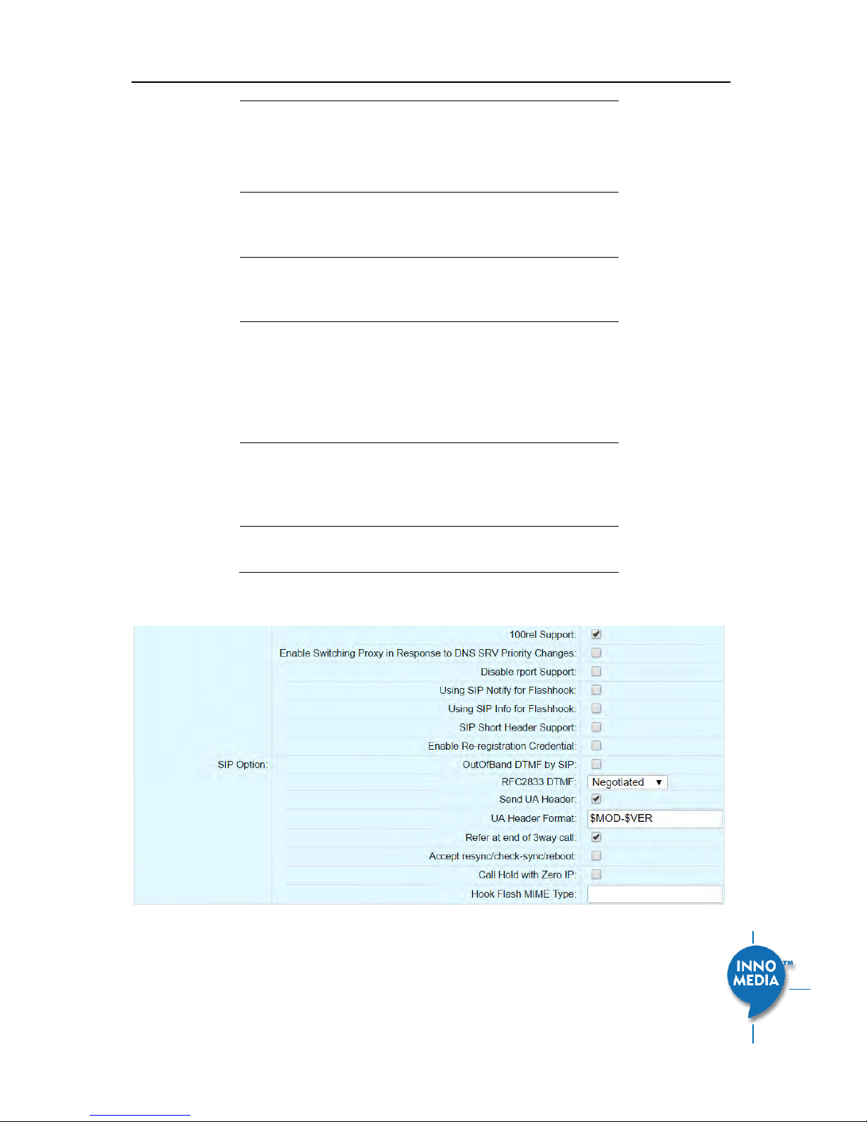
Figure 12. SIP Server Settings – SIP Option

InnoMedia 8328-1 Administrative Guide
Page 18
Copyright © 2017 InnoMedia. All rights reserved.
Field Name
Description
100rel Support
Enable 100rel response support.
Enable Switching
Proxy in Response
to DNS SRV Priority
Change
When this item is enabled, whenever the
MTA is ready to send a REGISTER request
and the SRV TTL has expired, it performs an
SRV query and the MTA will switch to the
most preferred SIP server (lowest priority) in
the SRV query response.
If this item is disabled, the MTA stays with
the currently registered SIP proxy and only
saves the SRV query results. However, if the
current SIP proxy is unreachable, or the MTA
reboots and starts a new DNS query process,
the MTA will then register to the most
preferred SIP server (lowest priority) in the
SRV query response.
Disable rport
Support
Do not append rport (response port
number) in the Via header.
Using Notify for
Flash Support
Send a SIP NOTIFY hook flash event message
during the call when a hook flash is
detected.
Using Info Flash
Support
Send a SIP INFO hook-flash event message
during the call when a hook flash is
detected.
Short header
Support
Send SIP Headers in short format (compact
form) to reduce message packet size.
Enable Reregistration
Credential
Enable Re-registrations to carry the previous
successful authentication credentials.
OutOfBand DTMF
by SIP
Use SIP INFO to send DTMF.
RFC2833 DTMF
Use RFC2833 for sending DTMF digits.
Available options:
Negotiated – MTA and SIP Server
negotiate if 2833 is enabled or not.
Always off – 2833 is never used.
Always on – 2833 is always used.
Send UA Header
Allow MTA to send User-Agent Header in SIP
message.
UA Header Format
User-Agent Header sent out is modifiable.
Note: If “hot heade “uppot is ealed,
 Loading...