

InnoMedia iPBX-124, iPBX-412 Quick Install Manual
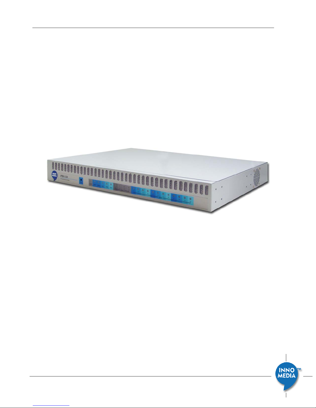
InnoMedia iPBX-412 Quick Install Guide
InnoMedia
iPBX-412 Quick Install Guide
Version 1.0
March, 2009
March 2009 - InnoMedia
1

InnoMedia iPBX-412 Quick Install Guide
Table of Contents
INSTALL IPBX IN YOUR CORPORATE NETWORK...........................................................................4
ADDING PHONES TO IPBX............................................................................................................7
CONFIGURE SIP TRUNK LINES WITH AN ITSP................................................................................8
VERIFYING COMMU NICATIONS ..................................................................................................9
PANEL LEDS.................................................................................................................................10
UPS LED ON WEB PAGE...............................................................................................................11
March 2009 - InnoMedia
2
Introduction
This document describes the ways to
− install iPBX in your corporate network
− create extension numbers, and assign devices to users
− configure SIP trunk lines with an ITSP
− verify communications
InnoMedia iPBX-412 Quick Install Guide
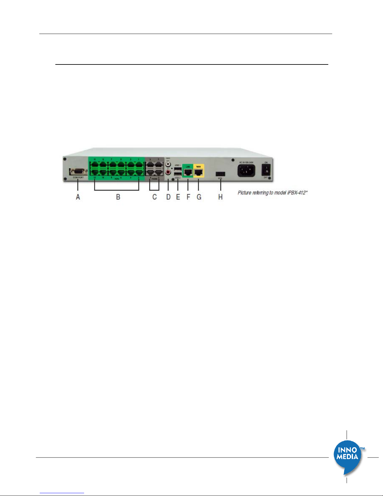
Figure 1. Hardware Interface
A. COM port
B. 12 FXO port for PSTN connection
C. 4FXS ports for legacy analog devices
D. 1 Audio In for MOH, 1 Audio Out for overhead paging
E. 2 USB host ports, for system restore/backup
F. 1 LANports for up to 256IP phones
G. 1 WANport
H. 1 UPS for battery backup
March 2009 - InnoMedia
3
Install iPBX in your corporate network
Step 1 - Connecting Panel Ports
InnoMedia iPBX-412 Quick Install Guide
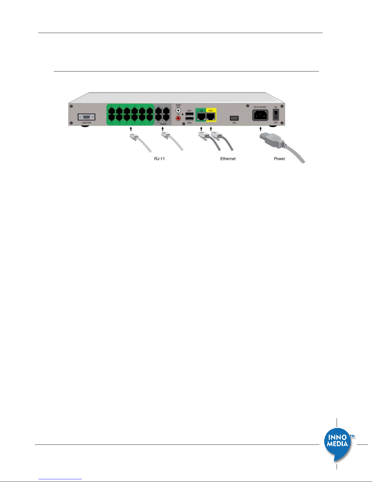
Figure 2 iPBX Hardware interface port
1. Connect the power cord to the iPBX.
Connect the power cord to the iPBX and power on iPBX. The Power LED will
then turn ON.
2. Connecting the LAN Port
Connect iPBX LAN interface to the hub or switch that is connected to your
internal network using RJ-45 Ethernet cable. The LAN indicator LED should
glow, if the LAN port is successfully connected to the local network.
3. Connecting the WAN Port
Connect iPBX WAN interface to the Internet router or Internet access device
by a RJ45 Ethernet cable. The WAN indicator Led should glow, if the WAN
port is successfully connected to the Internet.
4. Connecting the FXS Ports
Connect analog devices such as phones, FAX, or low speed modem (such as
credit card reader) to the FXS ports of iPBX via RJ-11 cables.
5. Connecting the FXO Ports (only available at model iPBX-412).
Connect external PSTN lines to FXO ports on the back panel of the iPBX-412
via RJ11 cables.
March 2009 - InnoMedia
4
 Loading...