

Page 1
InnoMedia
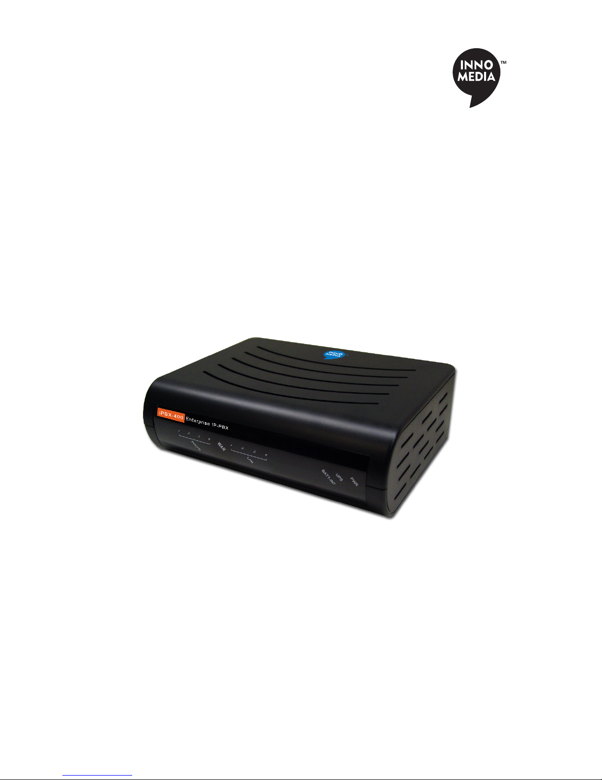
iPBX-400
Quick Install Guide
www.innomedia.com
Page 2

Table of Contents
Introduction 2
Package Contents 2
Installation 3
Wall-Mounting Instructions 5
Troubleshooting 6
Appendix A. LED Status Summary 7
Specications 7
Federal Communication Commission Interference State-
ment 8
1
Page 3

Introduction
The InnoMedia iPBX comes with all the IP-PBX features you’d expect and SIP Trunking,
the industry-accepted approach for direct IP peering to VoIP Service Providers. With SIP
Trunking enabled, the iPBX is capable of managing in a secured manner, an enterprise’s
telephony network.
Package Contents
The InnoMedia iPBX-400 comes with the following items:
1 iPBX
1 RJ-45 Cable
2 RJ-11 Phone Cables
1 AC/DC Power Adapter
1 Quick Install Guide
1 Battery Backup Supply
1 Wall-Mounting Template
1 CD
CAUTION
Disconnect power adapter from the equipment before removing the cover of the
battery compartment.
2
Page 4
Installation
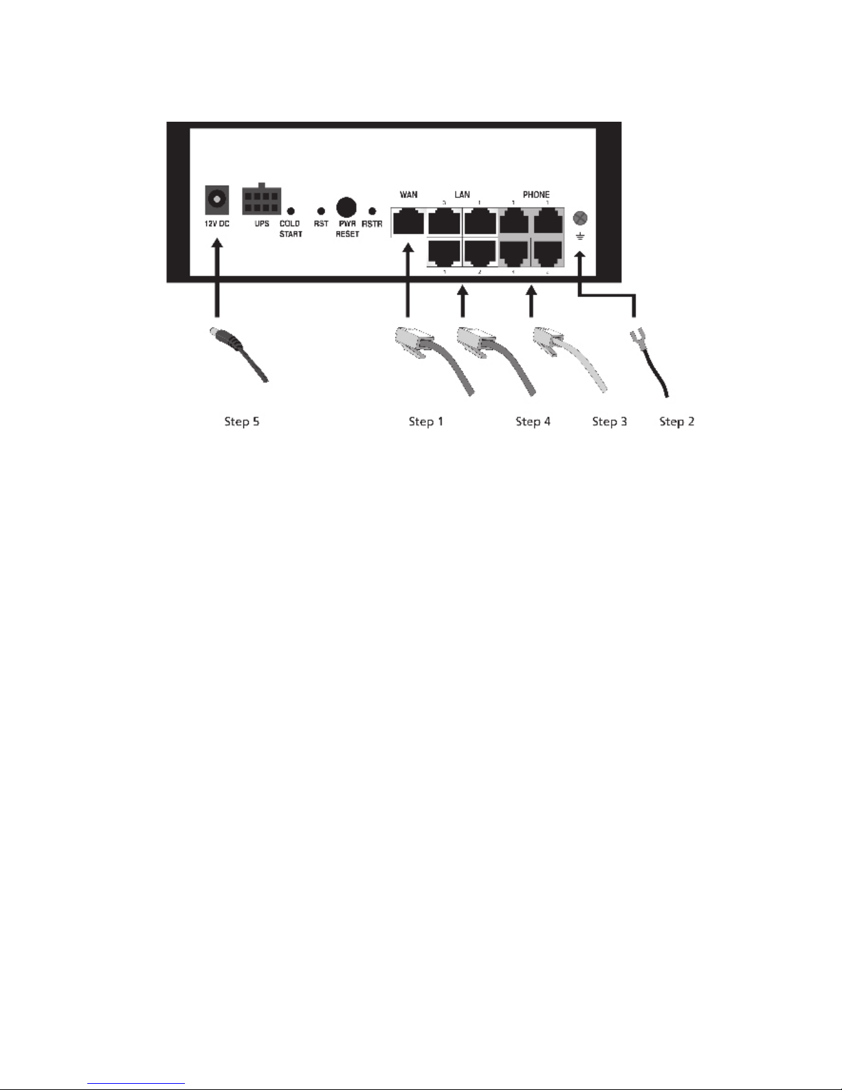
1. Connect the RJ-45 cable to the “WAN” connector.
2. Connect a grounding cable to be connected to the ground screw terminal as shown
in the diagram.
3. Connect any standard analog telephone or fax machine to iPBX’s “PHONE” connector, labeled 1-4.
4. Connect your PC to any LAN port using included RJ-45 cable.
5. Connect included AC power cable to the electrical outlet and its cable to the “12V
DC” connector.
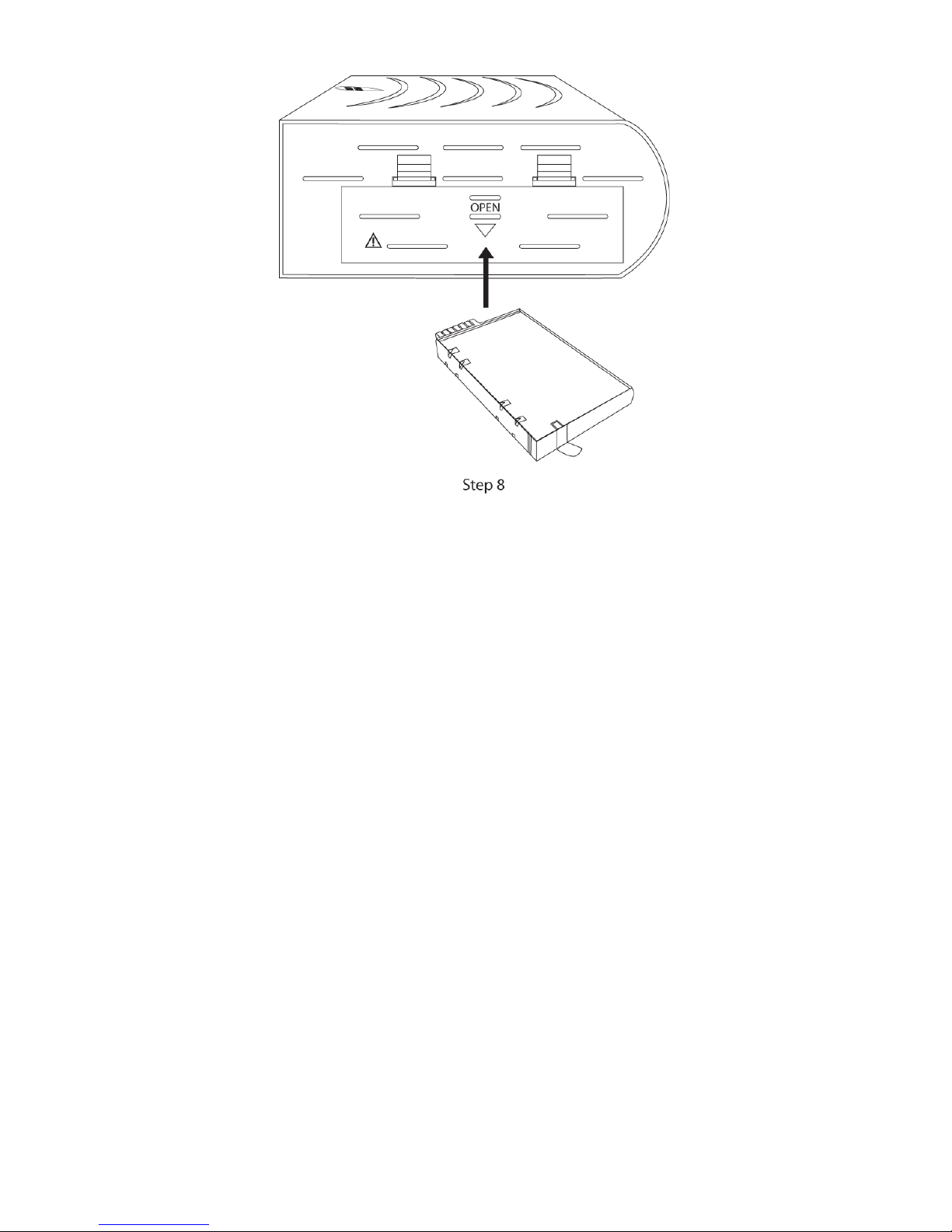
6. Optionally, open the battery compartment and insert the battery. Put the cover back
in place.
3
Page 5
7. Power on iPBX-400. If you have analog phones that are connected to iPBX-400
Phone interface, you may start placing and receiving telephones with the default
extension numbers, from 400 to 403.
8. Please refer to the administrative guide (in the CD), to start the network placement
and telephony plan for your enterprise. (Or you may download the latest document
from the following path: http://www.innomedia.com/support_manuals.shtml)
4
Page 6
Wall-Mounting Instructions
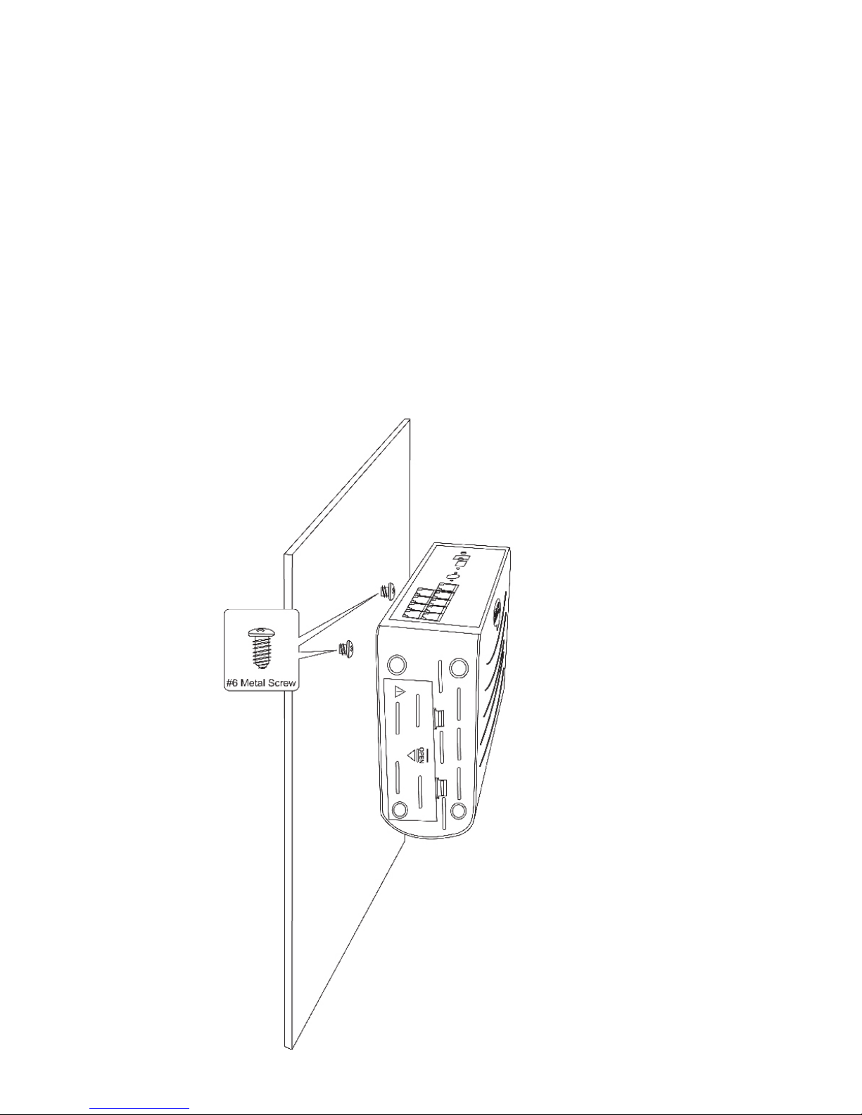
Optionally, you may choose to mount your iPBX-400 on the wall.
1. Use the provided template to drill two holes on the wall.
2. Use a screwdriver to install one #6 metal screw in each hole. Leave the screw heads
1/4 to 3/8 inch away from the wall.
3. Position the iPBX with the ports at the top.
4. Place the unit above the screws and lower it so the screw heads are inside and at the
tops of the wall mount slots on the back of the unit.
5. Adjust to t. If the unit is too loose, remove it from the wall, slightly tighten screws,
and rehang.
5
Page 7

Troubleshooting
Problem:
Telephone has no dial tone
Solution:
1. Ensure that all cables (power, Ethernet, telephone) are properly connected to the
iPBX. Ensure that iPBX’s AC power adapter is plugged in, and “PWR” indicator lights are
ON (see Front Cover Picture).
2. Pick up telephone handset (phone o-hook), check for corresponding Phone (1-4)
indicator light to be ON. Also, the “WAN” indicator light is Blinking Amber. If not, please
disconnect iPBX power cable, and then reconnect it again (see Front Cover Picture).
3. If previous steps fail, report the failure to service provider for attention.
Problem:
Cannot establish Internet connection.
Solution:
1. If the PWR, WAN, and LAN LEDs are lit, the iPBX is working properly. Try restarting
the computer so that it could reestablish a connection with the cable modem.
2. Power cycle the iPBX by switching the power to the O position, remove the power
adapter from the electrical outlet and plug it back in. Wait several minutes for the iPBX
to reestablish communications with your cable service provider.
3. If your PC is connected to a hub or gateway, try connecting the PC directly into the
iPBX.
4. Your Ethernet cable may be damaged. Try using another cable.
5. If none of these suggestions work, contact your cable service provider for further
assistance.
6
Page 8
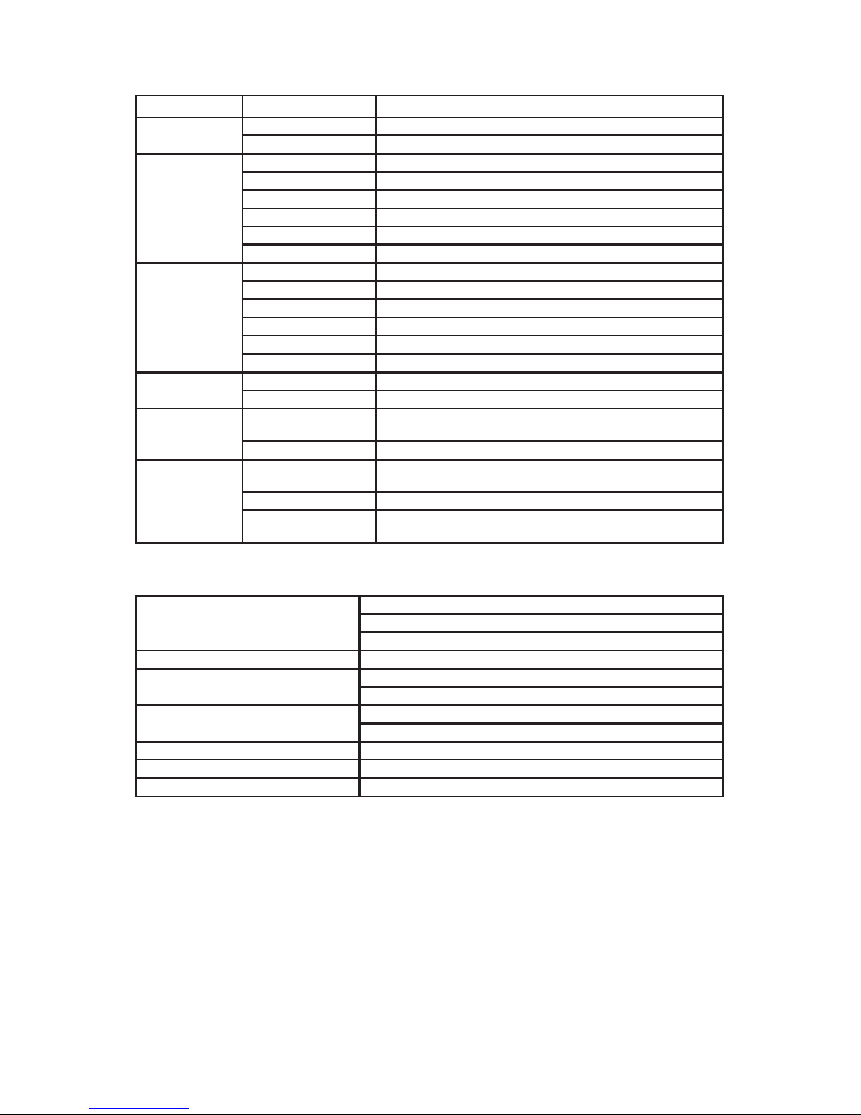
Appendix A. LED Status Summary
LED / Control Blinking State iPBX-400 State
PWR Steady Green Device power is on
O Device power is o
UPS Solid Orange Battery Fully Charged
Blinking Orange Battery is charging (AC power on)
Solid Green Battery is in use (AC power o)
Blinking Red Battery Low (AC power o)
Solid Red Failed or Bad battery (AC power o )
O Battery discharged (AC power o)
BATT-INT Solid Orange Battery Fully Charged
Blinking Orange Battery is charging (AC power on)
Solid Green Battery is in use (AC power o)
Blinking Red Battery Low (AC power o)
Solid Red Failed or Bad battery (AC power o )
O Battery discharged (AC power o)
WAN Blinking Amber When Data is passed through WAN Ethernet port
O No connection to Ethernet port
LAN 1-4 Blinking Amber When Data is passed while PC is connected to LAN Ether-
net port
O No PC connected to USB or LAN Ethernet ports
PHONE 1-4 Blinking Amber The connected telephone handset is on the hook (not in
use) and there are new voice mail messages
Steady Amber The connected telephone handset is o the hook
O The connected telephone handset is on the hook (not in
use) and there are no new voice mail messages
Specications
Telephone Interface 4 FXS voice ports
Connector RJ-11 REN=5
Signaling Loop start
Network Interface - Uplink Connector RJ-45
Network Interface - Downlink 10/100 Base-T
Connector RJ-45
Dimension 2.5 in (H) x 7.8 in (W) x 6.0 in (D)
63.5 mm (H) x 198 mm (W) x 152 mm (D)
Power Supply AC 100~240V/50~60Hz (DC 12V @ 4.0 Amps)
On Battery Li-ion battery providing 4 hrs Talk Time / 6 hrs Standby Time
Operating Temperature 32°F to 104°F (0°C to 40°C)
7
Page 9

Federal Communication Commission Interference Statement
This equipment has been tested and found to comply with the limits for a Class B digital device, pursuant to Part 15 of the FCC Rules. These limits are designed to provide
reasonable protection against harmful interference in a residential installation. This
equipment generates, uses and can radiate radio frequency energy and, if not installed
and used in accordance with the instructions, may cause harmful interference to radio
communications. However, there is no guarantee that interference will not occur in
a particular installation. If this equipment does cause harmful interference to radio
or television reception, which can be determined by turning the equipment o and
on, the user is encouraged to try to correct the interference by one of the following
measures:
- Reorient or relocate the receiving antenna.
- Increase the separation between the equipment and receiver.
- Connect the equipment into an outlet on a circuit dierent from that
to which the receiver is connected.
- Consult the dealer or an experienced radio/TV technician for help.
This device complies with Part 15 of the FCC Rules. Operation is subject to the following two conditions: (1) This device may not cause harmful interference, and (2) this
device must accept any interference received, including interference that may cause
undesired operation.
FCC Caution: Any changes or modications not expressly approved by the party responsible for compliance could void the user’s authority to operate this equipment.
IEEE 802.11b or 802.11g operation of this product in the U.S.A. is rmware-limited to
channels 1 through 11.
IMPORTANT NOTE:
FCC Radiation Exposure Statement:
This equipment complies with FCC radiation exposure limits set forth for an uncontrolled environment. This equipment should be installed and operated with minimum
distance 20cm between the radiator & your body.
This transmitter must not be co-located or operating in conjunction with any other
antenna or transmitter.
© 2010 InnoMedia Incorporated. All rights reserved. InnoMedia and the InnoMedia logo are trademarks of InnoMedia Incorporated. All other brand and
product names may be trademarks of their respective companies.
v1.2 1/10
8
 Loading...