

Page 1
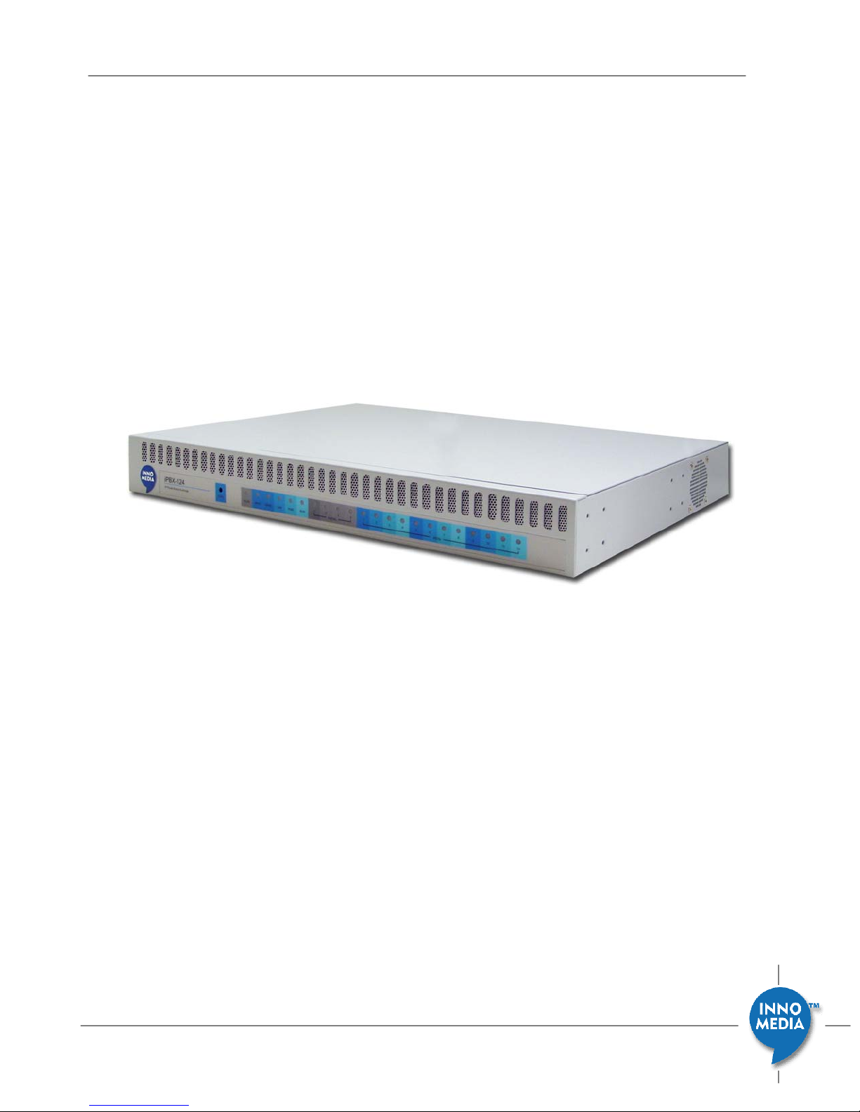
InnoMedia iPBX-412 Quick Install Guide
InnoMedia
iPBX-412 Quick Install Guide
Version 1.0
March, 2009
March 2009 - InnoMedia
1
Page 2

InnoMedia iPBX-412 Quick Install Guide
Table of Contents
INSTALL IPBX IN YOUR CORPORATE NETWORK...........................................................................4
ADDING PHONES TO IPBX............................................................................................................7
CONFIGURE SIP TRUNK LINES WITH AN ITSP................................................................................8
VERIFYING COMMU NICATIONS ..................................................................................................9
PANEL LEDS.................................................................................................................................10
UPS LED ON WEB PAGE...............................................................................................................11
March 2009 - InnoMedia
2
Page 3
Introduction
This document describes the ways to
− install iPBX in your corporate network
− create extension numbers, and assign devices to users
− configure SIP trunk lines with an ITSP
− verify communications
InnoMedia iPBX-412 Quick Install Guide
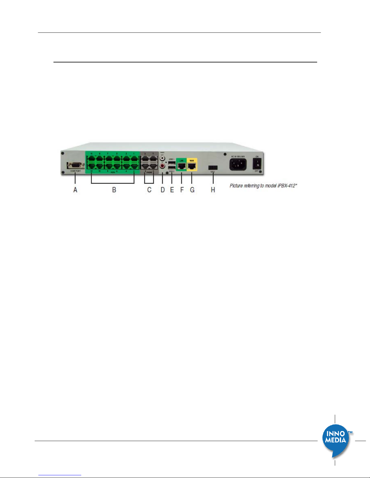
Figure 1. Hardware Interface
A. COM port
B. 12 FXO port for PSTN connection
C. 4FXS ports for legacy analog devices
D. 1 Audio In for MOH, 1 Audio Out for overhead paging
E. 2 USB host ports, for system restore/backup
F. 1 LANports for up to 256IP phones
G. 1 WANport
H. 1 UPS for battery backup
March 2009 - InnoMedia
3
Page 4
Install iPBX in your corporate network
Step 1 - Connecting Panel Ports
InnoMedia iPBX-412 Quick Install Guide
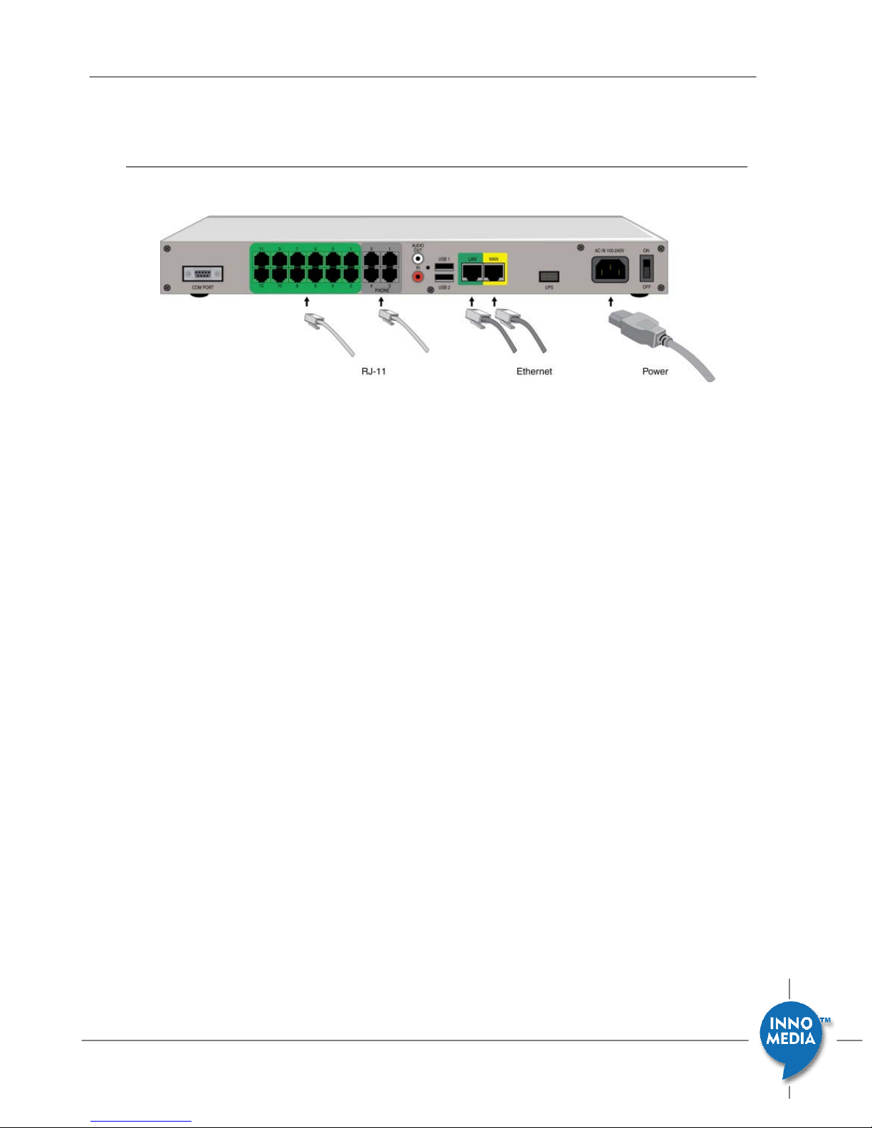
Figure 2 iPBX Hardware interface port
1. Connect the power cord to the iPBX.
Connect the power cord to the iPBX and power on iPBX. The Power LED will
then turn ON.
2. Connecting the LAN Port
Connect iPBX LAN interface to the hub or switch that is connected to your
internal network using RJ-45 Ethernet cable. The LAN indicator LED should
glow, if the LAN port is successfully connected to the local network.
3. Connecting the WAN Port
Connect iPBX WAN interface to the Internet router or Internet access device
by a RJ45 Ethernet cable. The WAN indicator Led should glow, if the WAN
port is successfully connected to the Internet.
4. Connecting the FXS Ports
Connect analog devices such as phones, FAX, or low speed modem (such as
credit card reader) to the FXS ports of iPBX via RJ-11 cables.
5. Connecting the FXO Ports (only available at model iPBX-412).
Connect external PSTN lines to FXO ports on the back panel of the iPBX-412
via RJ11 cables.
March 2009 - InnoMedia
4
Page 5
InnoMedia iPBX-412 Quick Install Guide
Step 2 – Check the administrative computer that configures iPBX
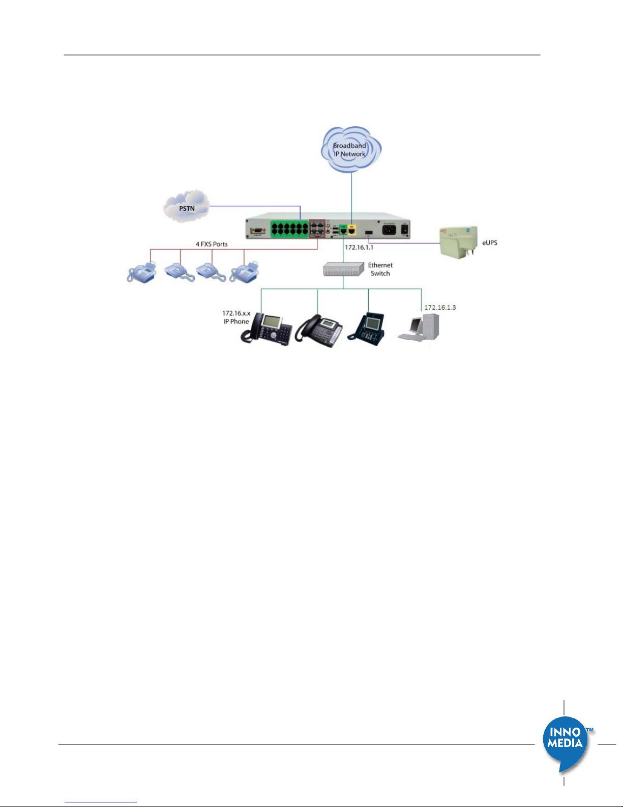
Figure 3 iPBX Network Placement (the picture is of model iPBX-412)
The iPBX configuration described in the Installation guide is for when the iPBX is
residing on a corporate network which is behind an existing corporate firewall. For
other placements of iPBX in the corporate network such as on DMZ or public network,
please refer to the Administration manual (which can be obtained from your
contact at InnoMedia).
1. The default LAN IP of iPBX is 172.16.1.1 with the Subnet Mask of 255.255.0.0. The
iPBX should be placed on the same LAN segment where your IP phones will
reside.
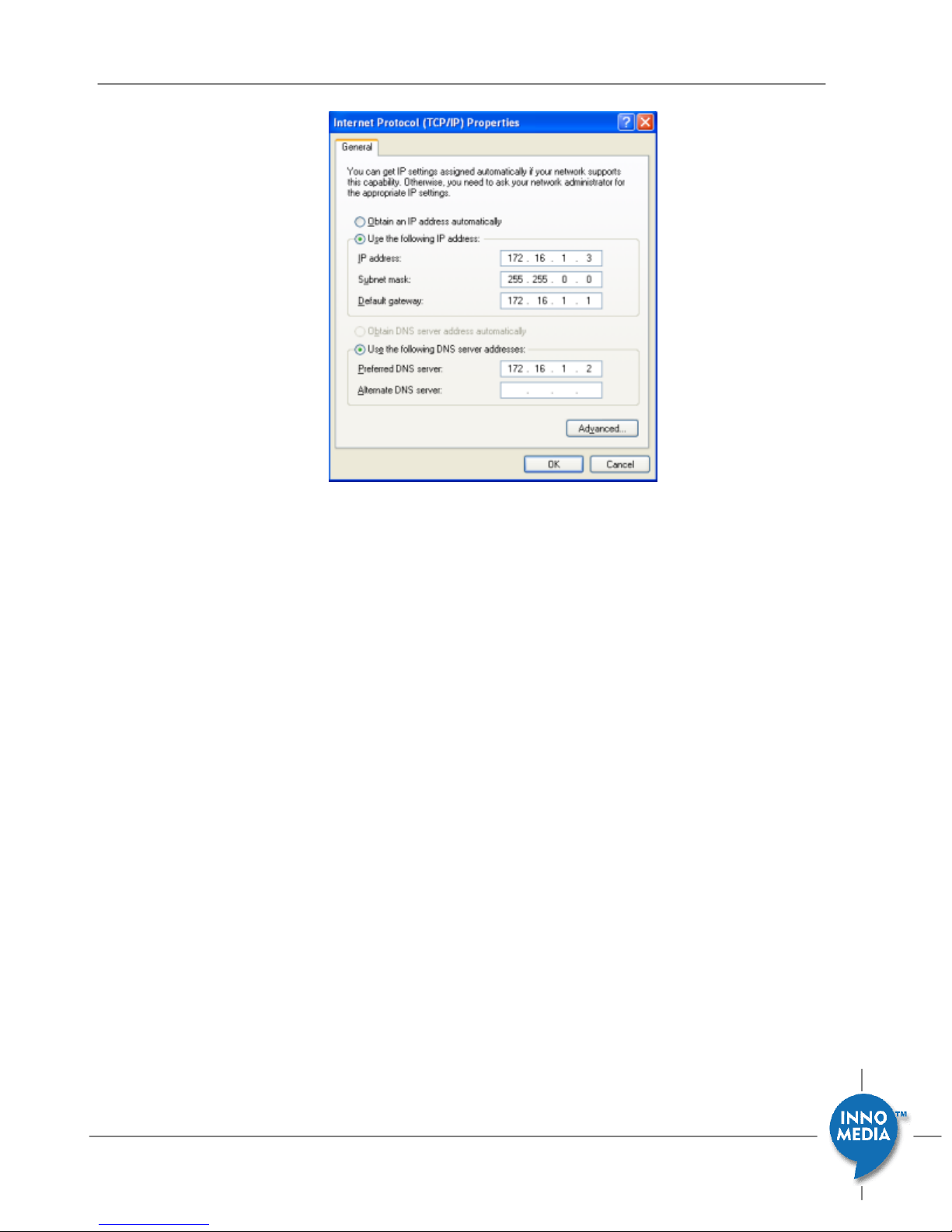
2. Configure your PC with appropriate IP address (i.e., 172.16.1.3) within the same
subnet as iPBX.
3. Connect iPBX LAN port to the administrative computer.
March 2009 - InnoMedia
5
Page 6
InnoMedia iPBX-412 Quick Install Guide
Figure 4. Configuring the IP address of the administrative computer
Step 3 - Configuring Network – LAN
Start your web browser, and enter “http://172.16.1.1” in the Address field to connect
to the iPBX. The login page will appear. The default User Name is “admin” and the
Password is “123”. Click the <Login> button to enter the iPBX home page.
A static IP address should be manually assigned to the server to avoid unexpected IP
address changes, which may result in a loss of connectivity. You should avoid DHCP
for iPBX LAN IP obtaining if possible.
1. To change the LAN settings, go to the page at “Network ÆSettingsÆLAN.
2. Give an appropriate static private IP address and associated netmask value that
you will assign to iPBX. For example, LAN private IP address for iPBX is
“172.16.20.33” with associated netmask as “255.255.255.0”. In any case, you
should check the network configurations of your organization.
3. iPBX automati cally reboots after you change the LAN IP add ress.
Step 4 - Configuring Network – Internet connection
1. Login to iPBX admin web console.
2. To change the WAN settings, go to the page at “NetworkÆ SettingsÆ Internet
Connection”.
March 2009 - InnoMedia
6
Page 7

3. Choose one Internet connection type from the ‘Connection Type’ drop-down list,
such as PPPoE, DHCP Client or Static IP.
4. Enter the required information provided by your ISP in the corresponding fields or
use any of default values. Click the <Ap ply> button.
5. If the WAN is successf ully configured to connect to the Internet, the “Connection
Status” should display “Connected”.
InnoMedia iPBX-412 Quick Install Guide
Step 5 - Configuring iPBX DHCP Server
IP-Phone and iPBX must connect to same subnet.
1. Go to the page of “Network
2. Make sure the “Starting IP Address” and “Ending IP Address” are configured to a
proper range.
3. If you desire the iPBX to manage the IP address of only the IP Phones then check,
“Only for managed devices”. Otherwise if you need the iPBX to manage the IP
address for both IP Phone’s and computers on the LAN, then ensure that “Only for
managed devices” is unchecked.
4. Check the “Enabled” check box and click the <Apply> button.
5. When the above configurations take effect the iPBX will start to manage and
provision the connected IP phone devices.
Æ
Settings Æ DHCP”.
Adding Phones to iPBX
Adding IP Phones to iPBX
There are two options to add IP Phones to iPBX.
Option A.
March 2009 - InnoMedia
Adding IP Phones in the auto discovery mode.
1. Connect IP Phones to local network and power them on. Be sure IP
Phones are at the same subnet with iPBX and WAN connection of IP
Phones are set to DHCP mode. (Please refer to the iPBX Web page
“System
device model list)
Æ
Provisioning Æ Device Provisioning” for the latest certified
7
Page 8

InnoMedia iPBX-412 Quick Install Guide
2. Go to the page of Telephony Æ Settings Æ Devices, and click the
<Discover> button and then th e new devices will appear in devi ce list
on the web page.
Option B.
Adding IP Phones and configuring associated extensions in a batch mode.
Configuring IP Phones, users, and associated extensions can be done
through importing the corporate IP telephony plan file in CSV format.
Please refer the steps from the iPBX administrative guide.
Configuring Analog Phone connecting to iPBX FXS ports
1. Go to the page of Telephony Æ Settings Æ Analog phones
2. The extension numbers assigned to FXS ports are preconfigured at iPBX from 10 to
13. You may change the extension numbers according to your telephony plan.
Configure SIP trunk lines with an ITSP
1. To configure a VoIP trunk, go to the page of Telephony Æ Settings Æ VoIP Trunks.
a) Click the button “Profile Config”, the “Profile Configuration” screen will appear.
b) Click the “Profile1” tab, enter the SIP Server IP address provided by your ITSP in
the SIP Proxy “HOST” filed, and if ITSP happens to have a SIP Domain, then
enter that to “SIP DOMAIN” field as well.
c) Click the button <App ly> then finish.
2. To configure SIP account, back to the page of “TelephonyÆ SettingsÆVoIP
Trunks”.
a) Click one VoIP trunk line from the list. The settings are displayed in the edit
section at the bottom of the page.
b) Enter “User ID”, “Auth ID”, “Auth Password”, select the profile you just
configured, and check the “Enabled” check box. Click <apply icon
> to
activate this trunk line.
3. If VoIP Trunk registers successfully, the status icon of this VoIP trunk will become
Green.
March 2009 - InnoMedia
8
Page 9

Verifying Communications
To monitor the on going call sessions, go to the page at TelephonyÆ MonitorÆView
Mode”.
Default telephony plan of iPBX is listed in the following table.
Description Default Value
Extension number of Analog Phone (FXS) 10 to 13
Extension number of IP Phone 30
Outbound Code for PSTN 5*
Outbound Code for VoIP None
1. Making an Internal Call
Making calls between extensions.
InnoMedia iPBX-412 Quick Install Guide
For example, ext “10” calls ext “30”.
Note that to expedite the call setup, press “#” after dialing all the digits.
2. Making an Outbound Call
Making an outbound call from an IP Phone extension (or an Analog Phone
extension) to an external phone number.
For example, ext. “30” calls “4325400” or “5*4325400”.
Note that to expedite the call setup, press “#” after dialing all the digits.
3. Making an Inbound Call
Making an inbound call to an IP Phone extension (or Analog Phone
extension).
For example, “4325400” calls an iPBX trunk line (either VoIP trunk or PSTN trunk).
By default, the auto attendant is enabled. Hence the caller will he ar the
voice prompt (“Hello, you have entered the Interactive Voice Response
service. If you know the extension number, please dial it now. For directory,
please dial 0.”), and then dial “30”. (You may change the auto attendant IVR
later.)
March 2009 - InnoMedia
9
Page 10

Panel LEDs
The below table describes each LED indicator.
LED Blinking State State
Steady - Green The device power is on. PWR
Off The device power is off.
RUN
WAN
FXS
the led will first be
green, then red, then
off, then steady green
Steady green Running normally
Orange blinking On provisioning
Red blinking Provisioning failed
Red/Orange blinking Sip trunk register failed
Blinking – Green
(10 Base T)
Blinking – Yellow
(100 Base T)
Off The device is not connected to a
Blinking – Green
(10 Base T)
Blinking – Yellow
(100 Base T)
Off The device is not connected to an
Blinking – Green (once) The FXS module is internally initialized
Steady-Green The connected telephone handset is
Blinking – Green (once) The connected telephone starts
Steady- Orange The connected telephone is talking.
Off The connected telephone handset is
System Booting
PC or Voice Data is being transferred.
broadband network.
PC Data is being transferred. LAN
external PC.
and the unit is ready to make calls
after booting.
off the hook.
ringing.
on the hook (not in use).
InnoMedia iPBX-412 Quick Install Guide
March 2009 - InnoMedia
10
Page 11
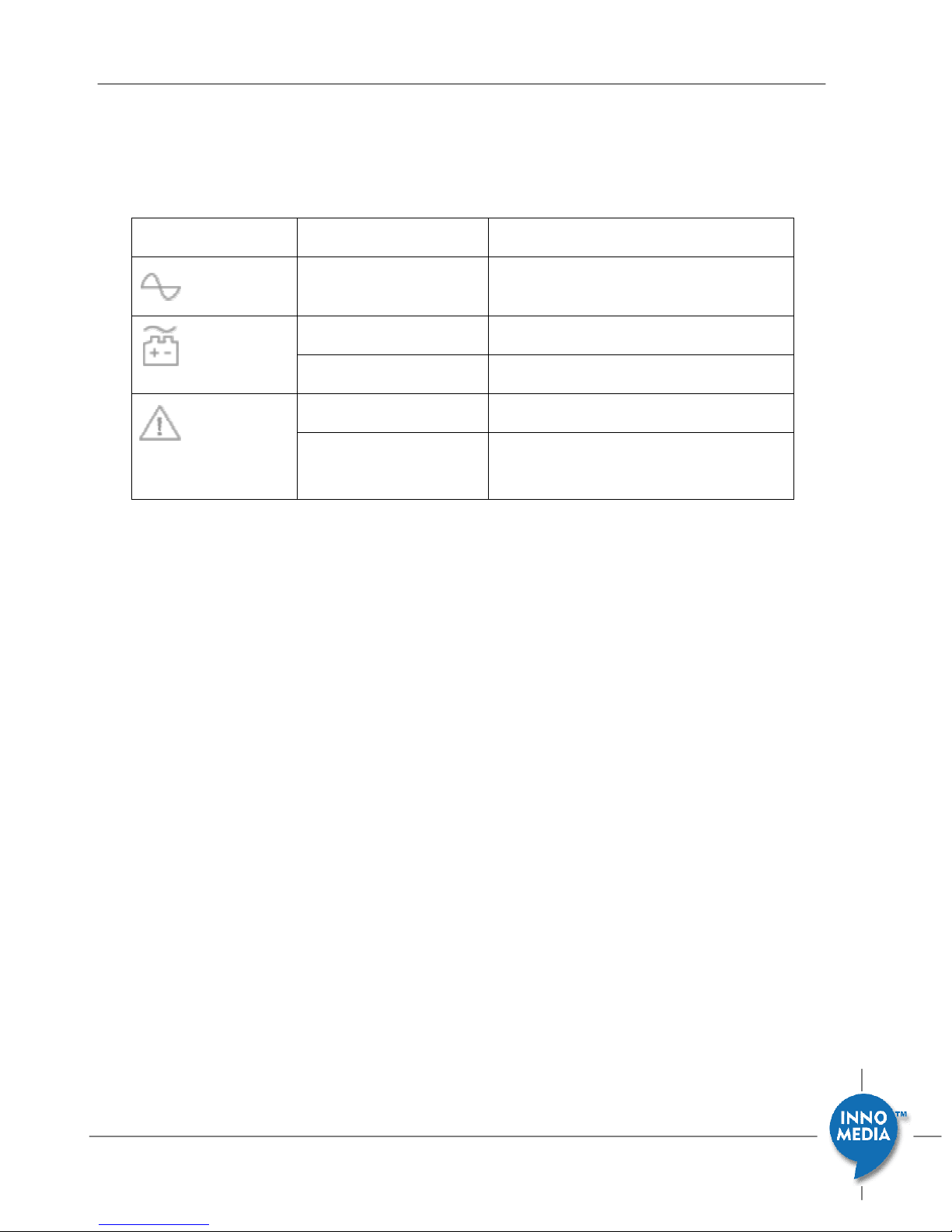
UPS LED on web page
Status Indicators Blinking State UPS State
Steady Green The UPS is on utility power. (AC Mode)
Steady Yellow The UPS is on battery power.
Blinking Yellow The battery is at a low state.
Steady Red The battery is missing.
Blinking Red The battery fails the Self Test. (Battery
replace)
InnoMedia iPBX-412 Quick Install Guide
March 2009 - InnoMedia
11
 Loading...