

INNOLUX MT215DW01-V1 SPEClFlCATlON
INNOLUX DISPLAY CORPORATION
MT215DW01 V.1 LCD MODULE SPECIFICATION
( ) Preliminary Specification
(●) Final Specification
Customer
Approved b y Checked by Prepared by
Innolux Display Corporation,
www.jxlcd.com
www.jxlcd.com
No.160 Kesyue Rd., Chu-Nan Site, Hsinchu Science Park,
Chu-Nan 350, Miao-Li County, Taiwan
Tel: 886-37-586000 Fax: 886-37-586060
Document Number: MT215DW01 V.1 –DR4-03

INNOLUX DISPLAY CORPORATION
MT215DW01 V.1 LCD MODULE SPECIFICATION
Department Prepared by Checked by
MKT
EE
www.jxlcd.com
www.jxlcd.com
PD
ME
TD
RA
Innolux Display Corporation
Document Number: MT215DW01 V.1–DR4-03
Version: 1.0
Record of Revision
Version Revise Date Page Content
InnoLux copyright
All rights reserved,
Copying forbidden.
1.0 2009/10/19
2.0 2009/12/18 12 T6
2009/12/18 15 Baklight unit parameter update
3.0 2010/01/25 7 Rear view of backlight update
2010/01/25 15 Backlight unit parameter update
2010/3/12 21 Module label update
www.jxlcd.com
www.jxlcd.com
First edition to all Final-Spec.
update to 50ms
Max
Contents:
SPEC NO.
PAGE
MT215DW01 V.1
4/24
A. General Specification
B. Electrical Specifications
1. Pin assignment 6
2. Absolute maximum ratings 8
3. Electrical characteristics 9
a. Typical operating conditions 9
b. Display color vs. input data signals 12
c. Input signal timing 13
d. Display position 14
e. Backlight driving conditions 14
5
6
C. Optical specifications
www.jxlcd.com
D. Reliability test items
E. Safety
F. Display quality
G. Handling precaution
H. Label
I. Mechanical drawings
www.jxlcd.com
16
19
20
20
20
21
23
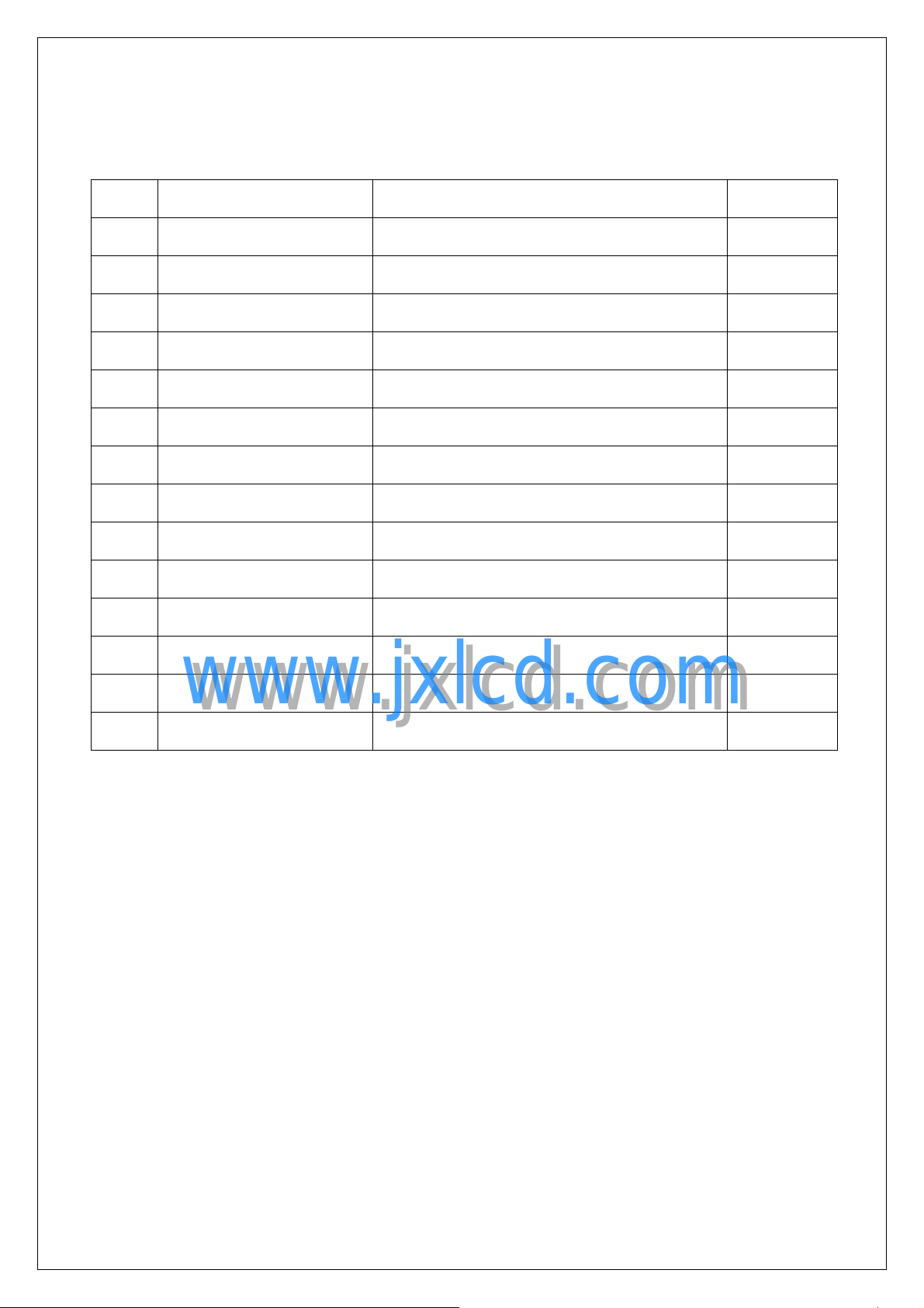
A. General specification
NO. Item Specification Remark
SPEC NO.
PAGE
MT215DW01 V.1
5/24
1 Display resolution (pixel)
2 Active area (mm)
3 Screen size (inch)
4 Pixel pitch (mm)
5 Color configuration
6 Overall dimension (mm)
7 Color Gamut
Weight (g) 1600 (Max)
8
9 Surface treatment
10 Input color signal
11 Display colors
12 Optimum viewing direction
1,920(H) X 1080(V), Full HD resolution
476.64(H) X268.11 (V)
21.53 inches diagonal
0.24825(H) X0.24825 (V)
R, G, B vertical stripe
495.6(W) X 292.2(H) X 9.8(D) (typ.)
70%
Anti-Glare, Hard coating (3H)
8 bit LVDS
16.7M (6 bit with Hi-FRC)
6 o’clock
13 Backlight
14 Others
www.jxlcd.com
www.jxlcd.com
White-LED
RoHS & TCO 5.0& Halogen Free compliance
SPEC NO.
PAGE
B. Electrical specifications
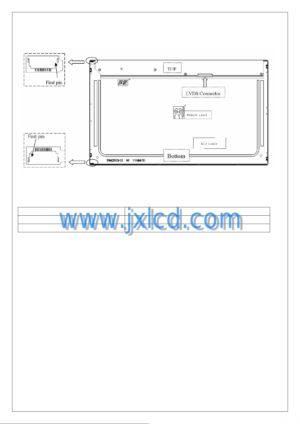
1. Pin assignment
Connector
FOXCONN GS23302-0011 R-7F or mechanical interface equivalent connector.
Pin No Symbol Description
Frame VSS Ground
1 RXinO0- -LVDS differential data input, Chan 0-Odd
2 RXinO0+ +LVDS differential data input, Chan 0-Odd
3 RXinO1- -LVDS differential data input, Chan 1-Odd
4 RXinO1+ +LVDS differential data input, Chan 1-Odd
5 RXinO2- -LVDS differential data input, Chan 2-Odd
6 RXinO2+ +LVDS differential data input, Chan 2-Odd
7 VSS Ground
MT215DW01 V.1
6/24
8 RXOC- -LVDS differential Clock input (Odd)
9 RXOC+ +LVDS differential Clock input (Odd)
10 RXinO3- -LVDS differential data input, Chan 3-Odd
11 RXinO3+ +LVDS differential data input, Chan 3-Odd
12 RXinE0- -LVDS differential data input, Chan 0-Even
13 RXinE0+ +LVDS differential data input, Chan 0-Even
www.jxlcd.com
www.jxlcd.com
14 VSS Ground
15 RXinE1- -LVDS differential data input, Chan 1-Even
16 RXinE1+ +LVDS differential data input, Chan 1-Even
17 VSS Ground
18 RXinE2- -LVDS differential data input, Chan 2-Even
19 RXinE2+ +LVDS differential data input, Chan 2-Even
20 RXEC- -LVDS differential Clock input (Even)
21 RXEC+ +LVDS differential Clock input (Even)
22 RXinE3- -LVDS differential data input, Chan 3-Even
23 RXinE3+ +LVDS differential data input, Chan 3-Even
24 VSS Ground
25 NC No Connection
26 NC No Connection
27 NC No Connection
28 VCC +5.0V power supply
29 VCC +5.0V power supply
30 VCC +5.0V power supply
Frame VSS Ground
SPEC NO.
PAGE
MT215DW01 V.1
7/24
Rear View of LCM
1.2. Recommend Connector for Backlight Unit
This connector is mounted on the monitor system board for LED light-bar FFC mating.
Connector Name/Designation Match Connector
Manufacturer Entery INDUSTRIAL CO.,LTD
www.jxlcd.com
Mating type part number 7080-Q10N-00R
www.jxlcd.com
1.3 Light-bar Connector Pin Assignment
Upper Light-bar Connector Pin Assignment:
Pin No Symbol Description
1 IRLED1 LED current sense for string 1
2 IRLED1 LED current sense for string 1
3 IRLED2 LED current sense for string 2
4 VLED LED power supply
5 VLED LED power supply
6 VLED LED power supply
7 VLED LED power supply
8 IRLED2 LED current sense for string 2
9 IRLED3 LED current sense for string 3
10 IRLED3 LED current sense for string 3
SPEC NO.
PAGE
MT215DW01 V.1
8/24
Lower Light-bar Connector Pin Assignment:
Pin No Symbol Description
1 IRLED1 LED current sense for string 1
2 IRLED1 LED current sense for string 1
3 IRLED2 LED current sense for string 2
4 VLED LED power supply
5 VLED LED power supply
6 VLED LED power supply
7 VLED LED power supply
8 IRLED2 LED current sense for string 2
9 IRLED3 LED current sense for string 3
10 IRLED3 LED current sense for string 3
www.jxlcd.com
www.jxlcd.com
 Loading...