

Page 1

Integrated Security and Access Control
User Manual
Page 2

Table of Contents
Introduction
About Inception 3
Site Details 4
System Notes 5
User Interfaces
Connecting to the Web Interface 6
Elite / EliteX Terminal 8
System Control
Area Control 9
Door Control 13
Output Control 15
Input Control 17
Users
User Management 18
Permission Groups 20
2
Scheduling
Time Periods and Calendars 22
System Administration
Database Backup 24
System Warnings / Messages 25
Reports 27
Review Events 28
Notications 31
Setting Date and Time 32
Network Settings 33
Dashboard Favourites 34
Page 3
Introduction
About Inception
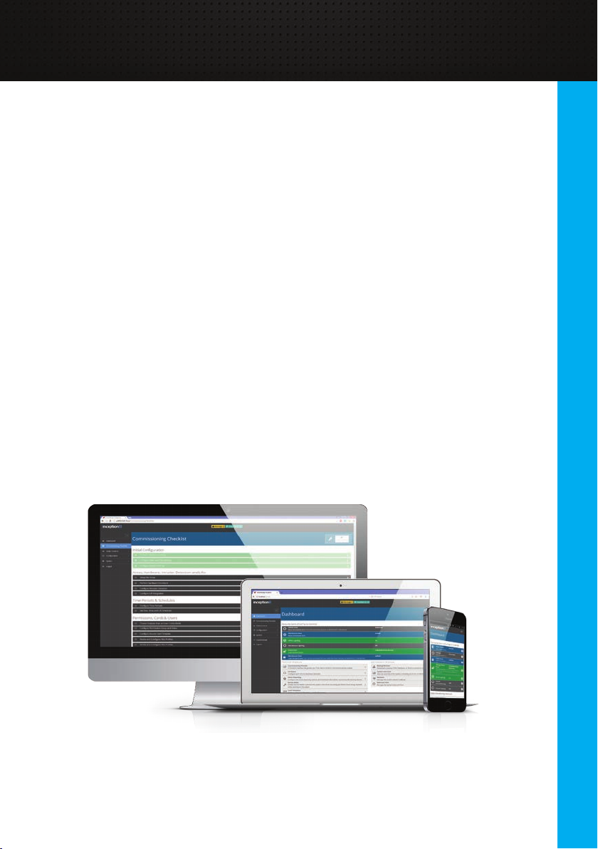
The Inception controller is an integrated access control and intruder detection
system featuring a powerful built-in web server. This allows you to monitor, control
and administer your site from any smartphone, tablet or computer with a network
connection. If an internet connection is available for your controller, the same web
interface can be easily accessed from any internet connected device.
This manual is intended to explain many of the features available to you, including
connecting to the user interfaces, controlling the system, managing the users and
ongoing system administration. However, the information in this manual is intended
as a basic guide only. For more in-depth information, there is detailed information
located at the top of each web page and in tooltips throughout the web interface.
Inception is a powerful system that can be congured in many different ways, so
some of the details in this manual may not apply to your system. Please contact
your installation technician for operating instructions for your system and for
information about the features that have been provided or congured.
System Control
3
Page 4

Introduction
Site Details
Installed By: _______________________________________________
_______________________________________________
Phone: _______________________________________________
Email: _______________________________________________
Monitored By: _______________________________________________
_______________________________________________
Phone: _______________________________________________
Email: _______________________________________________
Installation Date: _____________________________________________
4
Serial Number: IN____________________________________________
IP Address: _______________________________________________
Additional Information:
__________________________________________________________________
__________________________________________________________________
__________________________________________________________________
__________________________________________________________________
__________________________________________________________________
___________________________________________
Page 5

IntroductionIntroduction
System Notes
__________________________________________________________________
__________________________________________________________________
__________________________________________________________________
__________________________________________________________________
__________________________________________________________________
__________________________________________________________________
__________________________________________________________________
__________________________________________________________________
__________________________________________________________________
__________________________________________________________________
__________________________________________________________________
__________________________________________________________________
__________________________________________________________________
__________________________________________________________________
__________________________________________________________________
__________________________________________________________________
__________________________________________________________________
__________________________________________________________________
__________________________________________________________________
__________________________________________________________________
System Control
5
Page 6

User Interfaces
Connecting to the Web Interface
The web interface of Inception is the primary way of interacting with the system.
Inception’s web interface is designed to be responsive, meaning that you can use
the device of your choice, be it a computer, tablet or smartphone. Many different
browsers are supported, however it is recommended that the browser you use is
kept up to date to avoid issues.
The Inception controller’s web interface can be accessed via a local network or the
Internet.
Local Network Connection
If your device is on the same network as the Inception controller, it can be
accessed by typing the IP address of the controller into your device's web
browser. The IP address assigned to your device should be located on the “Site
Details” page of this manual, lled in by your installation technician.
SkyTunnel Internet Connection
If the network your Inception controller is connected to has internet access, you
can connect to the web interface from any internet-connected device. You will
require the serial number of your controller, which should be lled in on the
“Site Details” page. It is in the format INxxxxxxxx. To connect, navigate to
https://skytunnel.com.au/inception/SERIALNUMBER, where SERIALNUMBER
is the serial number of your Inception controller.
6
Logging In
Once you have browsed to the Inception web
interface, you will be presented with a login
screen. Enter your username and the password
to log in. Alternatively, a PIN can be used
instead of a password with PIN entry mode,
which may be better suited for touch devices.
On successful login, you will be taken to the
Dashboard screen of Inception.
Page 7
Connecting to the Web Interface (cont.)
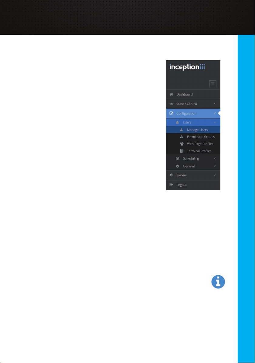
Navigating the Web Browser
The navigation bar on the left hand side of the screen
provides access to any part of the system. When browsing
from a smaller screen like a mobile device, the navigation
bar can be expanded by pressing the menu button at the
top right of the screen.
The current page is highlighted in blue and only the pages
you can visit are available. Any pages that you do not have
permission to visit are automatically hidden.
• The [State / Control] section contains pages for
monitoring and controlling the items in the system.
• The [Conguration] section is where the
conguration pages such as user management
and scheduling are located.
• The [System] section includes some system
administration tasks like downloading reports and
backing up the database.
Throughout this document, navigating to web pages will be indicated by bold
blocks like [Conguration > Users > Manage Users].
Accessing Help Information
Throughout the web interface, a signicant amount of help information is included
in each web page. At the top of each page, a sentence gives a brief introduction
to the page with a “Read More…” link that expands to show detailed information
about what the page offers and how to use the page. Similar information can also
be found on many of the dialogs that appear as you interact with the system.
When conguring items in the system, such as editing or adding users, tooltip
information icons are located to the right of each edit option. Clicking the icon
will show a tooltip popup for that edit option. This will include information that
describes what the option does, why it does it, how to use it and what
considerations to make when setting the option.
Logging Out
The web interface will remain logged in while the web page is open. Closing the
page will eventually close the session after some time, however for security it is
recommended that the [Logout] option is pressed from the navigation menu.
System Control
7
Page 8
User Interfaces
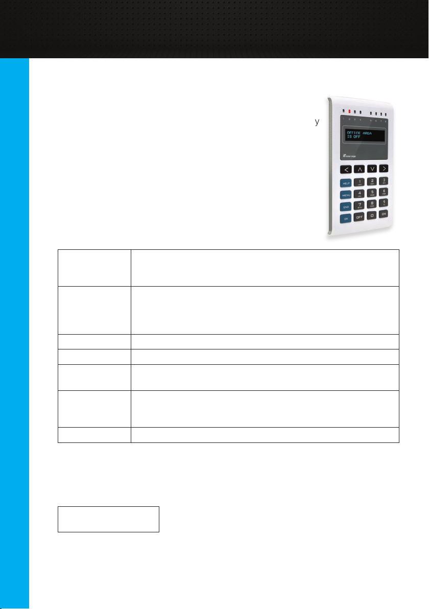
Elite / EliteX Terminal
In addition to the web interface, day to day control of the
system is also available via an Elite Terminal. This is a keypad
interface that is often used for controlling items such as security
areas or automation outputs.
Using the Terminal
The keys on the terminal perform specic tasks which help you
navigate the system. The below table describes the basic key
functions. How to perform specic functions will be discussed
later in the relevant sections.
[<], [^], [v], [>]
[HELP] The [HELP] key displays help text for the menu you are
[MENU]
[END] The [END] key logs you off from the terminal
[OK] Pressing [OK] is often used to accept changes or
Alpha-numeric
Keys
[ON], [OFF] The [ON] and [OFF] keys are used to control the selected item.
Logging On
Before controlling the system with the terminal, users must log on to the terminal by
entering their PIN (a unique number up to 8 digits long) and pressing [OK].
Code : ######
The terminal will automatically log off after 1 minute of inactivity.
The arrow keys are used to navigate within a menu. The up
and down arrows typically allow you to scroll through a list of
items, while left and right arrows may show additional options
currently viewing. Pressing the key multiple times shows
additional help text and eventually returns you to the
original screen
This key returns you to the main menu screen
acknowledge what is displayed on screen.
In addition to allowing numbers to be entered, the numeric
keys are used for selecting menus. For example, [MENU] [2]
[1] takes you to the Change PIN menu.
8
Page 9

Area Control
Areas are a core part of intruder detection; if your system is intended for access
control only, this topic can be skipped.
What is an Area?
An area commonly represents a physical location which groups all of the
detector devices in that location together. Those detector devices could be
movement detectors or magnetic door / window switches for example. When an
area is armed (turned on), that location is secured and any activity in that area is
considered to be unauthorised. When an intruder event occurs, sirens will often
sound and alarm messages are sent to the monitoring station. To stop the sirens
and acknowledge the alarm, the area needs to be disarmed (turned off).
Depending on how your system has been congured, there may be a single area
for the whole building or it could be broken up into many smaller areas. This allows
some sections of the building to be secure while others are not.
Disarming an Area
Disarming the area (or turning it off) disables intruder detection for that location
and allows people to move around in that area. Disarming also resets the state of
the area, cancelling anything that is currently active such as sirens during an alarm
or warnings during an entry procedure.
Arming an Area
When you attempt to secure an area, the system goes through an arming
procedure. The system automatically checks the state of the area and the system,
to ensure the area can be correctly secured. Any issues that occur during arming,
such as a door or window that is left open, will be displayed and should be xed
before attempting to secure the area again.
The common reason for a failed arm is the presence of unsecure inputs or
detectors in the area. In this case, you should check each input that is listed as it
could indicate that a door or window is not closed properly, or that there are still
people in the area.
An area can also fail to arm if there are alarm communication path issues or
hardware issues like AC Fail or battery problems. In these cases, you should
contact your installation company.
If the problem can’t be xed, such as a faulty input or a hardware issue, the issue
can be overridden (isolated) and the arm attempt tried again. However the issue
should be investigated as soon as possible.
System Control
9
Page 10
System Control
Area Control (cont.)
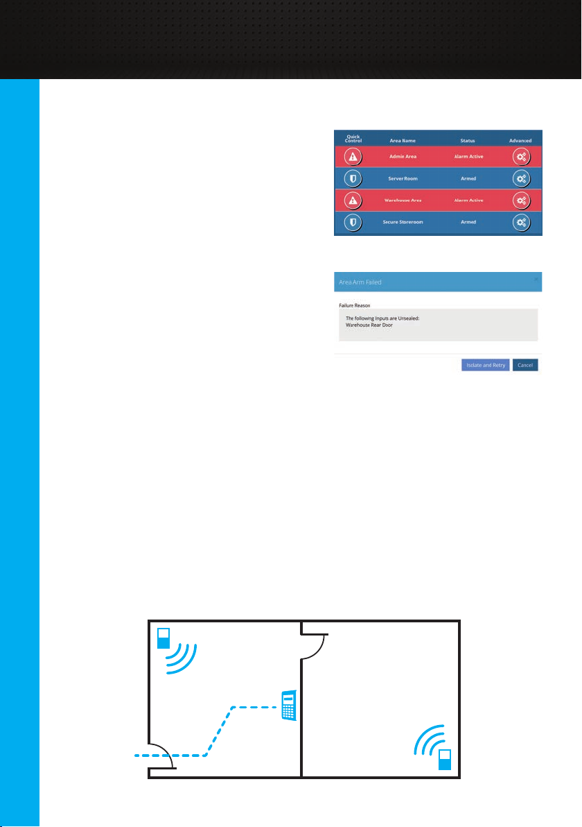
Controlling from the Web Interface
Once you have logged in to the web
interface (see the “Connecting to the Web
Interface” section), navigate to the [State /
Control > Control Areas] page. From there,
live state of all areas can be seen. The
“Quick Control” button can be used to easily
control the area based on its current state.
For example, a disarmed area will be armed,
while an armed area or an area in alarm will
be disarmed.
If an arm attempt fails, the reason will be
shown in a dialog. As mentioned previously,
the issue can be investigated, resolved and
the arm attempt tried again. If the issue can’t
be xed, the Isolate and Retry button will
override the issue and retry the arm again.
Elite Terminal Entry / Exit Paths
If Elite Terminals are installed in the building, they can be used to control the
security areas. Often, these terminals will be located inside the security area that
they control so they can’t be vandalised and tampered with. However this presents
the problem where the control of the area is performed within the secure area.
10
To achieve this, an entry / exit path is created between an exit door and the
terminal. This path is still protected by detectors, but if you enter the area through a
designated entry point then the path is temporarily ignored by the system for a
short amount of time, enough to reach the terminal and disarm the system.
Similarly, arming the area from the terminal will have a short delay (exit delay)
where you can walk along the path and leave without sounding the sirens.
Deviating from the path would be treated as an intruder event and cause the sirens
to sound.
Page 11
Area Control (cont.)
Elite Terminal Exit Procedure
To control areas from an Elite Terminal, you must rst log in with your PIN (see the
“Elite / EliteX Terminal > Logging On” section). Depending on your system setup,
you may be taken straight to the area control screen, but if not, press [MENU], [0]
to access area control.
Admin Area ^v
Is Disarmed
Pressing [^] and [v] will scroll through each of the areas that you have permission
to control. Once you have selected the area you want, pressing [ON] will attempt
to arm the area. If the arm fails, the failure message will be shown, along with a
scrollable list of items to investigate.
Arm Failed
Area Admin Area contained 1 unsealed inputs
Unsecure Items ^v
Warehouse Rear Door
On a successful arm, Exit Delay mode will begin.
Area Armed
Exit Area Now
Leave the area along the proper exit path.
Elite Terminal Entry Procedure
The entry procedure begins by entering the area through the correct entry point.
At that time, Entry Delay mode begins and various devices may beep to indicate
there is a short amount of time to disarm the system. Make your way to the terminal
along the entry path.
To control areas from an Elite Terminal, you must rst log in with your PIN (see the
“Elite / EliteX Terminal > Logging On” section). Depending on your system setup,
you may be taken straight to the area control screen, but if not, press [MENU], [0]
to access area control.
Admin Area ^v
In Entry Mode. Press OFF to Disarm
The area in entry mode should be shown. Press the [OFF] key to disarm the area.
System Control
11
Page 12

System Control
Area Control (cont.)
Admin Area ^v
Is Disarmed
Now, the area is disarmed. You can press [END] to log off the terminal.
Elite Terminal Quick Control
There is also a quick arm / disarm option available when using terminals. This is
a shortcut feature to quickly control an area as you log in to the terminal.
Code : ######
After entering your PIN, press the [ON] or [OFF] keys instead of [OK] to log in.
This will take you straight to the area control menu and attempt to arm or disarm
the area, without needing to press any other keys.
This option is a simple way to speed up both the entry and exit procedures when
controlling the area that the terminal is in. This depends on whether your
installation technician has associated an area with the terminal; please contact
them to verify if this feature is enabled.
12
Controlling with Access Cards
If your system utilises both intruder detection and access control, you may be able
to use your access card to control the area inside a door. Presenting your card
at the reader, in addition to unlocking the door, may be able to disarm the inside
area.
To arm the area, the access card can be presented three times in a row at the
same reader within a few seconds of each card swipe. Note that if this arm fails,
for example due to unsecure inputs, you should use the web interface or LCD
Terminal to attempt the arm instead. Contact your installation technician to see if
this feature is available on your system.
Page 13

Door Control
Doors are a core part of access control; if your system is intended for intruder
detection only, this topic can be skipped.
What is a Door?
A door in the Inception system controls an electronic lock on a physical door.
Doors restrict access to locations in a building. Permissions are granted to users to
determine which doors they can access and when.
Doors can be congured to automatically unlock on a schedule, such as the front
doors of a shop. If the door is locked though, a user must request access via a
credential reader linked to the door.
Credential Readers
Reader devices are typically located next to the door for the user to present a
credential. A credential is commonly an access control card or a PIN number, but
could also refer to biometrics such as a nger or eye scan. These credentials are
used to identify a user and request access through the door.
Depending on system conguration, especially for higher security areas, more than
one credential may be required to request access. For example, both a card and
PIN must be entered for access.
Door Override States
Doors will automatically unlock and lock throughout the day, based on
conguration. These states can be overridden if necessary:
• Unlocked: Overrides a normally locked door to be unlocked. This is useful
if people are constantly moving through the door, saving them needing
to present a credential each time.
• Locked: Overrides a normally unlocked door to be locked, restricting access.
• Lockout: Setting a door to the lockout override will prevent any access
control requests from being granted. Generally used in emergency situations.
Overrides should be cleared when they are no longer needed, returning the door
to normal behaviour.
System Control
13
Page 14

System Control
Door Control (cont.)
Doors Held Open Too Long
If congured by your installation technician the Inception system can detect that
a door is held open too long and sound beepers to alert someone to close it. This
feature is most commonly enabled on external doors.
This attempts to prevent doors that should be secure from having unauthorized
people gaining access through the door. If congured, after a door has been
opened, a timer will start to count. After some time, if the door has not been
properly closed, the readers, terminals or other noisemakers near the door may
start beeping to attract attention. This will continue for some time and if no one
closes the door, may be escalated and reported as an alarm event, so that
someone is contacted and the door closed.
If a door will be held open for a while, the unlock override feature should be used
to prevent the held open alarm from occurring.
Controlling from the Web Interface
Once you have logged in to the web
interface (see the “Connecting to the Web
Interface” section), navigate to the [State /
Control > Control Doors] page. From there,
live state of all doors is displayed.
14
The “Quick Control” button can be used to
easily control the door based on its current
state. For example, a locked door will be
briey granted access, an unlocked door
will be overridden to locked, and a door
with an overridden state will have the
override cleared.
Advanced control of the door can be used
to override a doors state if required. This
dialog lets you unlock, lock, lockout or clear
the override for a door, or grant temporary
access.
Page 15

Door Control (cont.)
Controlling from an Elite Terminal
To control doors from an Elite Terminal, you must rst log in with your PIN (see the
“Elite / Elite X Terminal > Logging On” section). The Door Control menu can then
be accessed by pressing the [MENU], [3], [2] keys.
Front Door ^v
Is Unlocked
From here, pressing [^] and [v] will scroll through each of the doors that you have
permission to control. Once you have selected the door you want to control,
pressing [ON] will override the door to Locked, pressing [OFF] will override the
door to Unlocked and pressing [OK] will temporarily grant access to the door.
Door Linked with an Elite Terminal
If a door is linked with a terminal, several other features may be available. Once
logged on, access can be requested through the door by pressing the [OK] key on
most menu screens. Commonly this would be the action [PIN], [OK], [OK].
Door Access
Requested
Similarly, if a door requires a Request to Exit button to be pressed to unlock the
door, a terminal can be congured to allow the [OK] button to act as a request to
exit button when logged off.
System Control
15
Page 16

System Control
Output Control
Outputs may be available to be controlled directly by users in the system using the
Inception interfaces. These could be connected to devices like room lighting,
air-conditioning, water sprinkler systems and many more.
Control Options
The control of outputs is fairly straightforward, allowing an output to be turned on
or off. Also, timed control can be used to automatically change the state of an
output after a period of time. This allows the water sprinklers to be turned on for 10
minutes for example, without needing to remember to turn them off.
Controlling from the Web Interface
Once you have logged in to the web
interface (see the “Connecting to the Web
Interface” section), navigate to the [State
/ Control > Control Outputs] page. From
there, live state of all outputs that can be
controlled is displayed.
The “Quick Control” button can be used to
easily control the output based on its
current state. This will turn on an output that
is off, or turn off an output that is on.
16
Advanced control of the output can be used for timed control, ranging from
seconds to hours.
Controlling from an Elite Terminal
To control outputs from an Elite Terminal, you must rst log in with your PIN (see
the “Elite / Elite X Terminal > Logging On” section). The Output Control menu can
then be accessed by pressing the [MENU], [3], [1] keys.
Admin Lighting ^v
Is On
Pressing [^] and [v] will scroll through each of the outputs that you have
permission to control. Once you have selected the output you want to control,
pressing [ON] will turn the output on and pressing [OFF] will turn the output off.
Also, pressing [<] or [>] will let you control the output for time. Pressing left will let
you control for minutes, pressing right will let you control for seconds. Type in the
duration with the numeric keypad and then press [ON] or [OFF] to control.
Admin Lighting ^v
For: 030 Mins
Page 17

Input Control
Inputs in Inception typically relate to the security detectors connected to the
system. The state of the Inputs cannot be controlled directly, as that is the
detectors job. However, if a detector is faulty, then the input can be isolated so the
system ignores the state.
Isolating Inputs
If an input is isolated, then the system will ignore its state and treat it as always
secure. Generally, isolation of inputs should only be done under the direction of
your installation technician, as it may compromise the security of the system. If the
input is faulty however, it could stop areas from being armed or cause alarms, so
isolating allows the input to be excluded from the system until it can be properly
xed. Once isolated, it will remain isolated until someone manually de-isolates it.
Controlling from the Web Interface
Once you have logged in to the web
interface (see the “Connecting to the Web
Interface” section), navigate to the [State /
Control > Control Inputs] page. From
there, live state of all inputs can be seen.
Isolating inputs is only available via the
Advanced Control button, showing a dialog
to allow control.
Controlling from an Elite Terminal
To control inputs from an Elite Terminal, you must rst log in with your PIN (see the
“Elite / Elite X Terminal > Logging On” section). The Input Control menu can then
be accessed by pressing the [MENU], [3], [4] keys.
Admin Detector ^v
Sealed
From here, pressing [^] and [v] will scroll through each of the inputs. Once you
have selected the input you want to isolate, pressing [OFF] will isolate the input,
excluding it from the system. Pressing [ON] will de-isolate the input, returning it to
normal operation.
System Control
17
Page 18

Users
User Management
A user is any person who interacts with the Inception system by either presenting
an access card, entering a PIN number, using a remote RF Fob or logging into the
web interface. User management is performed from the web interface. Once you
have logged in to the web interface (see the “Connecting to the Web Interface”
section), navigate to the [Conguration > Users > Manage Users] page
What Do Users Have
Users have a number of congurable options:
• Name: The name of the user. This is logged whenever the user
performs an action in the system, can be searched on for editing
and must be unique.
• Security PIN: If using Elite Terminals or keypads, this unique code can be
used to identify the user. By default, the PIN should be between
2 and 8 digits long. The Generate button can be used to generate
a unique, unused PIN.
• Credentials: This is the card or fob that can be presented to readers
to request access through a door. To help with adding a new card to
a user, recently presented unknown cards are displayed and can be
selected. This involves presenting the card to a reader and then when
adding a new credential to the user, the Add From Recent Card Reads
button can be pressed.
18
• Remote Fob: If RF Remote Fobs are used on site, they can be
assigned here. Similar to cards, a button on the new RF remote
can be pressed and when adding a new remote to the user, the
Add From Recent Fob Event button can be pressed.
• Web Login Details: If the user is allowed to access the web interface,
their username, password and web page prole can be congured.
The prole determines what pages they are allowed to see when they are
logged in.
• Email Address: Required for the user to receive email notications for
events. See the “Notications” section for more information.
• Permissions: Permissions determine what items a user can interact with
in the system and when they are allowed to. Multiple permissions and
permission groups can be added to each user. See the “User Permissions”
section later in this manual for more information.
Page 19

User Management (cont.)
Adding New Users – Guided Tour
If you are unfamiliar with adding users to the system, the best way to learn is via
the built-in guided tour of the web interface. This will take you through the full
process and will add the actual user along the way.
From the [Dashboard] page, a
Guided Tour shortcut should be
available at the bottom of the page.
Clicking this button will automatically
take you to the [Manage Users] page
and begin the tour. The tour will ask
you to name the user, congure their
credentials and assign their
permissions, before saving the user to
the system. The tour can be re-run as
many times as needed.
Updating Existing Users
After navigating to the [Conguration > Users > Manage Users] page, the user
you wish to edit can be selected from the list on the left. A search eld and sort
button is available to help nd the desired user. Once found, click on the user to
begin editing.
Make any changes as required to the user, such as
updating their credentials or permissions. Once complete,
the changes can be saved to the system using the Save
button in the toolbox at the top of the screen.
Users can also be deleted using the Delete button in the toolbox.
Changing PIN from LCD Terminal
A user is also able to change their security
PIN via an Elite Terminal. After logging in
with their current PIN (see the
“Elite / Elite X Terminal > Logging On” section),
the change PIN menu can be accessed by
pressing the [MENU], [2], [1] keys.
Type the new PIN with the number keys and then
press [OK]. The PIN number must then be
re-entered to conrm the PIN and the [OK]
key pressed.
Set New PIN:
_
Conrm New PIN:
_
User PIN
Changed
System Control
19
Page 20

Users
User Permissions
Permissions are used to determine what areas, doors and outputs a user can
access and control within the system and when those actions are allowed to be
performed.
Permissions
Permissions are created using a What and When structure. The What determines
the items they are allowed to control and in what way. The When determines when
this permission applies. For example, a user is only able to access a door during
working hours.
20
Permissions can be assigned to users in one of two ways. The rst method is
to add individual items such as doors, areas or outputs directly to a user. This
method offers a lot of exibility, however, it can become difcult to manage once
the site grows to more than a few users. The second and preferred method is to
use permission groups.
Permission Groups
As a system grows in size, it is common for multiple users to share the same sets
of permissions, for example if they work in the same department or have similar
roles. In this case, permission groups can be used to create a set of permissions
once and then assign that set of permissions to many users. That set can also be
updated in future and the changes will automatically be applied to all users with
that permission group.
Permission Groups can be congured via the web interface. Once you have
logged in to the web interface (see the “Connecting to the Web Interface” section),
navigate to the [Conguration > Users > Permission Groups] page.
Page 21

User Permissions (cont.)
Managing Permissions
Permissions across the site can be managed in many ways. When creating
permission groups it is recommended to rst identify what is common between
users. Many permission groups can be assigned to the same user and
permissions groups can also reference other permission groups, opening up
many options to manage the site permissions. Some common examples are
listed below:
• Role Based: Permission groups could be created based on the users’ role
in the company, such as IT Staff, Admin Staff, Warehouse Staff etc. In
this case, all of the doors, areas and outputs that a warehouse worker
needs access to can be assigned to the Warehouse Staff group. As new
personnel are hired, they can be assigned a permission group that matches
their role.
• Hierarchy Based: A hierarchy can also be used to manage permissions.
A Basic level group could be created with all doors and areas that everyone
requires. Then different permission groups can include that basic group and
add extra permissions, like for a management level. Then, the correct level
can be assigned to a user.
• Building/Department Based: A site with multiple buildings, oors or
departments could create different permission groups for each individual
section. Users can then be assigned the multiple different permission groups
based on the sections of the site that they need to acess.
These techniques could also be combined to help organize the site’s permissions
and simplify user management.
System Control
21
Page 22

Scheduling
Time Periods and Calendars
Time Periods and Calendars are the main tools used to provide scheduling
functionality in the Inception system. A time period will become active and inactive
based on the current date and time. They can then be used for many reasons,
such as to restrict when a user is allowed to do certain actions, automatically
unlock doors or automatically arm areas. Time periods are only congured from the
web interface. Once you have logged in to the web interface (see the
“Connecting to the Web Interface” section), navigate to the [Conguration >
Scheduling > Time Periods] page.
Time Periods
Time periods are broken up into two parts. First are the weekly recurring times
where time blocks can be congured for each day of the week when the time
period should be active. This could allow Monday to Friday, 9am to 5pm to be
congured for example. The second part is the exceptions to those rules, which
override the weekly recurring times.
Calendar exceptions are the most common exception for time periods. In this case,
the exception time range is set and a Calendar item is created to provide the dates
when this exception should occur.
Calendars
As mentioned, calendars are intended to be active on specic dates of the year,
which can then be used with time periods for exceptions. Calendars are available
from the [Conguration > Scheduling > Calendars] page. There are 3 types of
dates that can be congured:
22
• Single Dates: Individual dates can be set that optionally occur annually.
• Date Ranges: All days between a start and end date would be active.
• Calculated Dates: A calendar event that isn’t a specic date or date range.
Allows for example, the “second Tuesday of every month” to be congured.
Scheduler
The Scheduler page (available from [Conguration > Scheduling > Scheduler]),
can be used to congure when doors should automatically unlock and lock, when
areas should automatically arm and when lift oors should be in free access. This
page allows those schedules to be changed directly, without accidentally
changing core conguration settings.
Page 23

Time Periods and Calendars (cont.)
Example – Trading Hours
A common example of time periods and calendar exceptions is a trading hours
time period that controls the front door of a shop. During trading hours, this door
should be unlocked, so a time period is used to control this. Each week, the door
should be open from 9 am to 5 pm, Monday to Friday, so weekly recurring times
are used. Many days throughout the year, extended trading hours occur from 7 am
to 7 pm. For this, a calendar exception is used where the 7am-7pm range is
congured with an “extended trading hours” calendar. Then, any days when
extended trading hours should occur can be entered into the calendar. Similarly,
several days occur in the year when the shop should be shut. In this case, another
calendar can be used to represent that, when the time period should not activate
at all.
Once set up, the calendar items can be edited each year without needing to touch
the time periods directly. Those calendar items can also be used in many other
time periods, making managing of the business schedule much easier.
Calendar Preview
To verify if your time periods and calendars are congured correctly, there is a
Calendar Preview option available on each page. This can be used to look at any
day in the future, to see what times a time period would be active, or what days a
calendar is active on.
System Control
23
Page 24

System Administration
System Warnings / Messages
System Warnings and Messages are the Inception controller’s way of notifying
users about important events. If there are any issues, the system administrator or
the installation or maintenance technician should be contacted.
System Warnings
A system warning highlights any issues that are currently present in the system.
These could indicate issues with connected modules, such as connectivity issues
or power issues. Warnings should be xed as soon as possible, as they could be
preventing the system from running optimally. Your installation or maintenance
technician should be contacted when warnings occur to ensure issues are xed
completely.
System Messages
Where system warnings highlight current issues in the system, system messages
are used to notify about important events that happened in the past and are no
longer present. Often when a system warning is xed, a message is created to
ensure someone knows the issue occurred. This ensures that the information about
those events does not go unnoticed. A message can also occur following an alarm
that includes an alarm summary. When a system message occurs, the message
just needs to be acknowledged by someone to remove it.
System Messages
Once you have logged in to the web
interface (see the “Connecting to the Web
Interface” section), notication icons will
be shown at the top of every page if any warnings or messages are present. The
messages and warnings can be seen on the [System > System Overview] page,
or the notication icons can be clicked as a shortcut to that page.
24
System messages and warnings can
then be seen, with messages in blue and
warnings in orange. Messages will detail
the event and will include an
Acknowledge button.
Warnings will include any available
information about the event and if
possible, some information about how to
resolve the issue and shortcut buttons to
help resolve or nd more information.
Page 25

System Warnings / Messages (cont.)
Viewing from an Elite Terminal
Warnings can be viewed and messages can be acknowledged from an Elite
Terminal, however the amount of detail is limited. The web interface should be
used to see more detailed information.
To interact with system warnings and messages from an Elite Terminal, you must
rst log in with your PIN (see the “Elite / Elite X Terminal > Logging On” section). If
there are messages or warnings present, and no currently active alarms, the
warnings and messages menu should automatically open. Alternatively, the
warnings and messages menu can be accessed by pressing the [MENU], [6], [1]
keys.
Sys Events: ^v
Messages 1 >
Sys Events: v
Warnings 2 <
This menu will show both the messages and warnings in the system, with the arrow
keys used to navigate and view the information. The [<] and [>] keys switch
between Messages and Warnings modes. The [^] and [v] are then used to scroll
up and down through the events. For warnings, the information can only be
viewed, they can’t be interacted with. For messages, pressing [OK] will
acknowledge the selected message. As there could be many messages, scrolling
to the top will give an option to acknowledge all messages at once.
Press OK to v
Acknowledge all messages
System Control
25
Page 26

System Administration
Database Backup
A database backup allows a copy of all of the conguration options in the system
to be downloaded. Taking regular database backups of the system is important
so that if something happens to the system, the latest conguration and changes
aren’t lost.
If something happens to the Inception system, such as environmental issues like
a power surge, the backup can then be restored without data loss. Similarly, if
an accidental programming change is made that is difcult to undo, restoring the
database backup can revert the change quickly.
Backups should be taken regularly and stored in a safe location as losing the user
updates over the last few months can be frustrating to re-add.
Backup from the Web Interface
Once you have logged in to the web interface (see the “Connecting to the Web
Interface” section), navigate to the [System > Backup / Restore] page. From
there, the “Download Backup” button will download the backup to your device. The
“Download Backup to USB Drive” option is only used if there is a USB drive
connected to the controller.
26
Page 27

Reports
The Inception system can generate many different reports. They can be used to
summarise conguration settings for the system or retrieve a history of user
interactions with the system. Reports can only be generated by the web interface.
To generate the reports, login to the web interface (see the “Connecting to the Web
Interface” section) and navigate to the [System > Reports] page.
Generating Reports
For each report type, various lter information can be congured to customize
the report output. For example, the access history report could be ltered to only
include specic doors to see who accessed a room, or specic users to see where
they have been.
To generate a report, select the type of report
you want, choose the report le format, lter as
required and then press the Create Report
button in the toolbox at the top of the page.
This will download the report to your device.
Report Formats
Inception can generate reports in PDF and HTML formats. PDF reports are limited
in size, while a Multi-PDF option can create many PDFs that are packaged together
into a zip le. HTML reports do not have the size limitation and can be as large as
necessary. New reporting formats may be added to the Inception system in future
rmware updates.
Review Event Reports
In addition to the built-in report types, the review events page can be used to
retrieve history about the site. With the search and category ltering, review can
be shown about many aspects of the system. Once ltered as desired, the visible
review events can be downloaded as PDF or CSV to your device. See the “Review
Events” section for more information.
System Control
27
Page 28

System Administration
Review Events
Review events are a historical log of every event that has occurred in the Inception
system. These events are often viewed when issues occur, when investigating
incidents or to see who has interacted with the system. The Inception controller
can store up to 250,000 review events and when the limit is reached, the oldest
events are automatically removed. Depending on how busy the site is, this could
allow many months of activity to be stored.
Events
Each event is made up of a number of parts: the event message, when the event
happened, who generated the event, what was affected and where the event
occurred. Depending on the event, there may not be a relevant who, what or
where. An event is grouped into one of ve categories, namely security, access,
hardware, system and audit events. These categories can help in focusing on the
type of events you are interested in.
Viewing Events
Events are most commonly viewed from the web interface. The events can be
viewed by logging into the web interface (see the “Connecting to the Web
Interface” section) and navigating to the [State / Control > Review Events] page.
The events that occurred in the last 24 hours
(up to a maximum of 500 events) will
automatically be loaded, with new events
dynamically added to the top of the list.
More events can be loaded by pressing the
Load More button in the toolbox,
loading an additional 500 events each time the button is pressed. Alternatively,
clicking Load all will load all events to the web browser; however this may take
some time.
28
Page 29

Review Events (cont.)
Filtering Events
Several ltering options can be used to nd particular events in the system. Events
can be ltered by time, content or category and the lters can be used individually
or combined for advanced searching. The text-based content search will search
across the Message, Who, What and Where columns and each word entered can
appear in different columns.
Exporting Events
Review events can be downloaded in
either CSV or PDF formats via the
buttons in the toolbox. The downloaded
events are affected by the applied
lters and will only include what has
been loaded and is visible.
Exporting Events
An Elite Terminal can also be used to view past review events if required. After
logging in with your PIN (see the “Elite / Elite X Terminal > Logging On” section),
the events menu can be accessed by pressing [MENU], [1]. From there, all events
can be seen by pressing [1], or the event category can be selected with [2-6].
Event Logs:
1=All 2=Security 3=Access 4=Hardware 5=System 6=Audit
Once selected, the [^] and [v] keys can be used to scroll through the messages
one at a time.
System Control
29
Page 30

System Administration
Area Walk Test
Area walk tests allow for periodic testing of the detectors and buttons within an
area to ensure they are functioning correctly. This includes all of the movement,
door and window detectors. More importantly, it also includes the infrequently used
inputs like medical, smoke, emergency or duress buttons. When arming (turning
on) an area, the detectors are only checked to see if they are secure. However if
an input has become faulty, it may always report as secure and won’t be protecting
the building.
Starting a Test
Area walk tests can only be started from the web interface. Once logged in (see
the “Connecting to the Web Interface” section), navigate to the [State / Control >
Area Walk Test] page.
Each area in the system is displayed and from here, walk tests can be started and
stopped. Multiple areas also can be tested at once if desired.
During a Test
An area walk test allows the inputs to be activated without triggering an alarm,
allowing the emergency response inputs to be tested without the emergency
response.
Once a test has been started, all inputs that need to be tested are listed. To test an
input, it must change from an active state to a secure state. This could involve
walking in front of a movement detector, opening and closing a window or pressing
and resetting the emergency or duress button for example. As they are tested, they
will automatically move to the “Passed” list.
30
A test will automatically complete when all inputs in the area have been
successfully tested. If some inputs can’t be tested, then the test can be cancelled
early.
For more information about starting and performing walk tests, see the help
information on the area walk test page in the web interface.
Page 31

Notications
Inception is capable of sending notication messages via email using clear, easy
to read language. Conguration of notications is incredibly exible, allowing
different users to be notied about different events at different times.
When multiple events are to be sent to the same person, they are automatically
consolidated into a single email message.
Email Server – Technician Only
To send emails, the Inception controller needs the details of an SMTP server. The
conguration options for this server are located on the system settings page, which
requires the installation technician to congure.
Notiers
Conguration of email notications can only be made from the web interface. Once
logged in (see the “Connecting to the Web Interface” section), navigate to the
[Conguration > General > Notiers] page.
A notier is congured with a list of recipient users to send message to, an optional
schedule for when to send the messages and what events should be notied on.
Users can be notied on almost any type of event in the system. Area notications
can be sent when alarms occur, when arm or disarm attempts are made or when
abnormal behaviour occurs like an area being armed or disarmed at the wrong
time. Doors can be monitored for unauthorized access attempts or when doors
have been left open too long. Repeated failed login attempts to the Web Interface
or Terminals can also be sent, along with many other system health issues.
Multiple notiers can be congured with different recipients and different
schedules to allow exibility. Unauthorized access requests can be sent to
administrators, while other events like low battery for RF devices can be sent to
maintenance personnel for example.
System Control
31
Page 32

System Administration
Setting Date and Time
Keeping the date and time of the Inception controller correct is important to ensure
that any scheduled events occur at the correct time. User permissions and
automatic door unlocking or area arming can be controlled based on a schedule,
so problems could occur if the controller time is out by even a slight amount.
Any conguration or modications of the system date and time is achieved via the
web interface of Inception. Once logged in (see the “Connecting to the Web
Interface” section), navigate to the [Conguration > General > Date and Time]
page.
NTP Server
By default, Inception is congured to keep its time automatically in sync with NTP
(Network Time Protocol) servers if an internet connection is available. This is the
same way that computers keep in sync. This is the recommended way to keep the
Inception controller’s time accurate, so either an internet connection should be
provided or if one is not available, a local NTP server to sync with.
Manually set the time
If no NTP server is available, either
due to no internet access or no
server available on site, then the
date and time can be updated
manually.
32
Pressing the Set Date/Time Manually button will show a dialog window where the
time can be congured. The current time of the browser can also be used with this
method. Pressing OK will set the specied time to the Inception controller.
Time Zones and Daylight Savings
Specifying the time zone where the controller is located will allow the NTP time
syncing to convert correctly to the local time. Also, Daylight Savings for the
Inception Controller is automatically handled with the time zone that is specied.
Page 33

Network Settings
If the web interface of the Inception controller becomes inaccessible or the
network address of the controller needs to change, editing of network settings may
be required.
The Inception controller includes a built-in Ethernet connection that can be
congured with a static address or as DHCP. Changes to the Ethernet settings can
be made from either the web interface if it is accessible or an Elite Terminal.
If the Inception Wireless Adapter has been purchased (available separately),
Inception can connect as a client to the local Wi-Fi network. Conguration of the
wireless settings can only be made from the web interface with an Ethernet
connection.
Conguring via the Web Interface
If a connection can be made to the web interface, log in (see the “Connecting
to the Web Interface” section) and navigate to the [Conguration > General >
Network] page. On this page, both the Ethernet settings and the Wi-Fi settings are
congured.
Conguring via an Elite Terminal
The Ethernet settings can be checked and updated via an Elite Terminal. After
logging in with your PIN (see the “Elite / Elite X Terminal > Logging On” section),
the network settings menu can be accessed by pressing [MENU], [5], [2].
IP Addr Type ^v
DHCP <>
If set to DHCP, the [^] and [v] keys can be used to view the automatically assigned
network settings. The [<] and [>] keys can be used to change between DHCP
and Static modes. If set to static, the IP Address, Subnet Mask, Gateway and DNS
Server can be congured. When conguring an address, the [<] and [>] keys are
used to change the focused number and the number keys enter the value. When
all settings have been congured, the [OK] key will commit the changes to the
system. Up to 1 minute may be required for the changes to take effect.
System Control
33
Page 34

System Administration
Dashboard Favourites
The web interface for Inception is
the primary way of interacting with
the system, allowing full control and
viewing of live state from a computer,
tablet or smartphone. This can be
enhanced further with dashboard
favourites, where the areas, doors
and outputs which are often
interacted with can all be shown in
one place.
The [Dashboard] page is the default
rst page that is shown after logging
in. If the favourite items are
congured, then the full system
status can be seen and controlled at
a glance without needing to navigate
to other pages.
Conguring Dashboard Favourites
Dashboard favourite items are linked to web page proles. Web page proles are
assigned to users and determine what pages they are allowed to see when they
log in to the web interface. The same prole can be assigned to many different
users, so managing and updating of favourites can be done in one place. Different
favourites can also be congured for different proles, allowing some users such
as managers to see more items and other users to have a simpler interface with
only a couple of items.
34
Web proles and dashboard favourites are congured on the [Conguration >
Users > Web Page Proles] page of the web interface. The prole you wish to edit
can be selected from the list on the left. Once found, click on the prole to begin
editing. The dashboard favourites are congured in the Dashboard Content
section, with the Items to View/Control option. Click the Add Items button and
select the items to include as a favourite. If you want a specic order for the
favourites, add the items one at a time. Once complete, the changes can be saved
to the system using the Save button in the toolbox at the top of the screen.
Note: Including an item as a favourite item only allows it to be displayed on the
dashboard. A user’s ability to control the item will still depend on their permissions.
Page 35

System Control
35
Page 36

Inception, SkyTunnel and SIFER are registered trademarks of Inner Range Pty Ltd. Product specifications subject to change without notice.
Pictures shown may vary from actual product.© 2018 Inner Range Pty Ltd all rights reserved. Part Number: 636300UM - 51020
 Loading...