

Page 1
INSTALLATION AND
PROGRAMMING MANUAL
Section 0. Title and Document Version log. (This sheet)
Section 1. Installation Manual.
Section 2. Introduction to Programming and System Overview.
Programming Reference:
Section 3. General Options.
Section 4. Times.
Section 5. Areas.
Section 6. Zone Inputs.
Section 7. System Inputs.
Section 8. Auxiliary Outputs.
Section 9. Terminals.
Section 10. Communications.
Section 11. Users.
Section 12. Quick Programming. (Includes Programming record sheets)
Section 13. Index.
Contents
© 2002. Inner Range Pty. Ltd. Part Number: 630047
Page 2

p2 Section 0. Title. Version 1.02 CONCEPT IQ. Installation & Programming Manual.
SECTION TITLE CURRENT VERSION
-AS AT 16 JAN 2002
0 Title and Document Version log (This sheet) 1.02
1 Installation Manual 1.01
2 Programming Introduction 1.01
3 General Options 1.01
4 Times 1.01
5 Areas 1.01
6 Zone Inputs 1.01
7 System Inputs 1.02
8 Auxiliary Outputs 1.01
9 Terminals 1.02
10 Communications 1.01
11 Users 1.01
12 System Planning & Programming record sheets 1.02
13 Index 1.02
Document Revisions
This table shows the current Version numbers of all documents in the “Concept IQ Installation and Programming Manual”.
This table can be used when checking the Website for updates. http://www.innerrange.com
When you replace any documents in this manual with new Versions, ensure that this table is updated or replaced with the
latest Version from the Website.
Inner Range Pty Ltd is proud of the reputation it has gained in the provision of high quality electronic products. Exhaustive
factory and field testing ensure that enhanced system programming features and additional hardware components operate
as expected prior to their release to our customers. Extensive function testing is carried out on every Inner Range Concept
product prior to it leaving the factory.
It is our intention to completely satisfy the requirements of our customers. To that end, Inner Range Pty Ltd stands behind
its products with confidence. A Two Year Warranty accompanies every Inner Range Concept product. Should any
Concept product fail to function as intended by the manufacturer within this period, it should be returned to the distributor
and the fault or symptom detailed. Inner Range will, at its own discretion, repair or replace the product as soon as possible.
This Warranty does not cover product failures occurring wholly or in part as a result of misuse, malicious damage,
accidental damage or acts of nature.
1) The manufacturer and/or it’s agents take no responsibility for any damage, financial loss or injury caused to any
equipment, property or persons resulting from the correct or incorrect use of the Concept IQ system and its
peripherals. The purchaser assumes all responsibility in the use of the Concept system and its peripherals.
2) Whilst every effort has been made to ensure the accuracy of this manual, Inner Range Pty Ltd assumes no
responsibility or liability for any errors or omissions. Due to ongoing development the contents of this manual is
subject to change without notice. Check regularly with your supplier or the Website for updates.
Disclaimer
Warranty
Page 3
CONCEPT IQ. Installation & Programming Manual.
Install
p1
SECTION 1.
INSTALLATION.
1. Installer and Master User Operations (NEXT functions) ...........2
2. Control Module ...........................................................................3
3. LED Terminal..............................................................................7
4. Programming Key ....................................................................... 8
5. Enhanced LED Terminal.............................................................9
6. Expansion Card ..........................................................................11
7. DTMF Card .................................................................................13
NOTE: Factory Default PIN Codes:
User 1. Installer: 2 3 4 5
User 2. Master User: 0 1 2 3
Contents
Page 4

Section 1. Installation. CONCEPT IQ. Installation & Programming Manual.p2
Adding / Changing / Deleting Users. NEXT 20 See Section 11: Users
View history. NEXT 21
Press to view the Next Event. Press to view the Previous Event.
If the are no further events to be displayed, one long beep will sound.
History Event Types: Arm: <ARM> Lamp. Armed in Home Mode: <HOME> Lamp.
Dis-arm: <ARM> and <0> Lamp. Zone Input in alarm: <Zone 1> to <Zone 16> Lamp.
System Inputs in alarm: <0> Lamp.
Walk test mode. NEXT 22
Press to switch between Alarm Test Mode and Tamper Test Mode.
Any Zone Input in the Terminal’s Associated Area that goes into the Alarm (Un-sealed) or Tamper state will cause:
- The corresponding Zone Lamp to fast flash on an Alarm state in Alarm Test Mode.
- The corresponding Zone Lamp to slow flash on a Tamper state in Tamper Test Mode.
- The Siren to sound for 3 seconds.
- The Terminal beeper to emit a short beep.
Setting the Real-Time Clock. NEXT 23 See Section 4: Time Programming.
Auxiliary Control and Test mode. NEXT 24
Enter the Auxiliary Output number (1 or 2 digits);
then Press: to turn the Auxiliary ON OR: to turn the Auxiliary OFF..
When testing the Auxiliary, remember to return the Auxiliary to it’s original state before exiting Auxiliary Control Mode.
Fault Analysis mode. NEXT 25 See Section 7: System Inputs
System Inputs that are currently in Alarm will be indicated by Fast flashing on the relevant Zone Lamp. (See "System Input Mapping" in Section 7)
These Alarms cannot be acknowledged until the problem is rectified.
Acknowledge any previous Faults and Alarms.
Press . System Inputs that have been in Alarm but subsequently restored since the last Acknowledgement will be indicated by Slow flashing on the
relevant Zone Lamp. Note the datails of the Alarm/s displayed.
Press to Acknowledge and Clear any of the Faults or Alarms that are not currently in Alarm.
IMPORTANT NOTES: 1) Press to toggle between the “Current Alarms” & “Previous Alarms” displays.
2) Zone Self-test (Lamp 10) can only be cleared from “Zone Self Test Display” Mode (NEXT 26).
3) Door Alarm (Lamp 15) can only be cleared from “Acknowledge Door Alarms” Mode (NEXT 29).
Zone Self Test display. NEXT 26
The Zone 1 to Zone 16 Lamps will indicate any Zones that have failed the Zone Self Test so that appropriate action may be taken. e.g. A detector fault
may need to be rectified by the Installer. Press to acknowledge any Zone Self Test faults.
Edit Telephone numbers. NEXT 27 See section 10: Communications.
View Software Version number. NEXT 28
The 1st digit of the 4-digit Version number is displayed by the corresponding Zone Lamp flashing.
To display each of the remaining digits of the Version number press the key..
Acknowledge Door Alarms. NEXT 29
Door Alarms will be indicated by the relevant Zone Lamp 1 to 4. Note the datails of the Alarm/s displayed.
Press to Acknowledge any Door Alarms.
De-Isolate System Inputs. NEXT 90 De-Isolates any Isolated System Inputs.
Test Siren speaker and Strobe (Aux. 1). NEXT 91 Triggers Siren and Strobe (Aux 1) for 3 Seconds.
Battery Test. NEXT 92 Switches off the Battery charger for 5 seconds.
Test Transmission. (Test report) NEXT 93 Triggers Test report via selected Dialer format.
Day Alarm on / off. NEXT 94 Toggles Day Alarm Enabled/Disabled.
Reset Latching Auxiliaries. NEXT 96 Resets all latched Auxiliaries.
Answer Phone NEXT 97 Forces Control Module to answer incoming call.
Reset Smoke Detectors. NEXT 99 Triggers the “Smoke Detector Reset” Aux Event.
Installer and Master User Operations.
Page 5

CONCEPT IQ. Installation & Programming Manual.
Install
p3
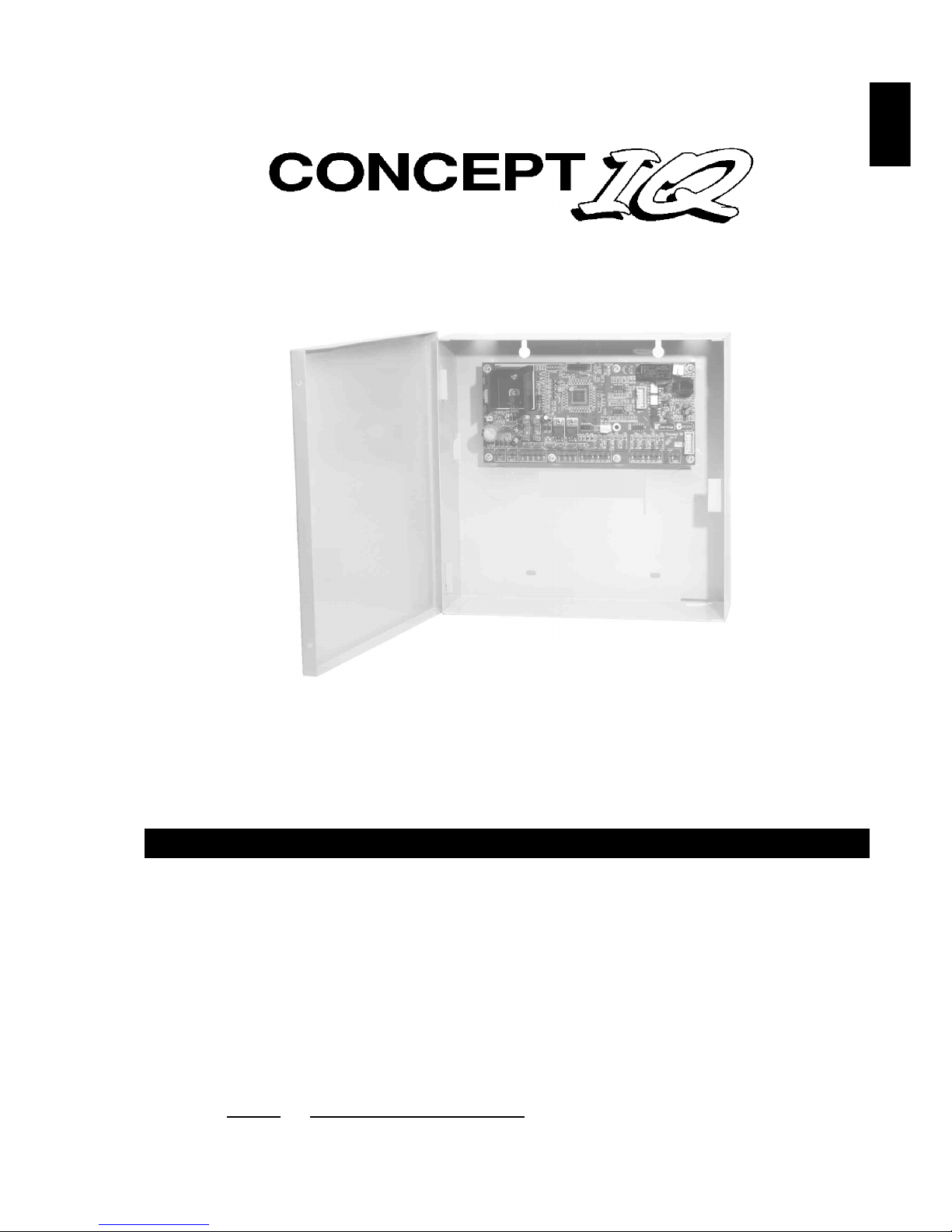
Control Module. 995501
Control Module Parts List
- Control Module PCB mounted in metal enclosure.
- User Manual.
- Installation Manual. (This document)
- Installation Kit containing:
- 4 x Pan Head Self-tapping screws 4x6mm. Used to secure the enclosure cover.
- 5 x plastic “D” bungs. Must be fitted to all unused cable entry cutouts in the cover.
- Telecom Line cord. (Note: Non-standard configuration. Only suitable for use with this product)
- 10 x 3k3 End-of-line resistors. (orange-orange-black-brown-brown) Used for Single EOL / Dual EOL / Zone Doubling.
- 10 x 6k8 End-of-line resistors. (blue-grey-black-brown-brown) Used for Dual EOL or Zone Doubling.
- 10 x 1k End-of-line resistors. (brown-black-black-brown-brown) Used for Zone Doubling.
- Tamper switch.
- Tamper switch bracket.
- 2 x 6 Way plug-on screw terminals. (Only for PCBs that do not have fixed terminal blocks fitted)
- 1 x 3 Way plug-on screw terminals. (Only for PCBs that do not have fixed terminal blocks fitted)
- 5 x 2 Way plug-on screw terminals. (Only for PCBs that do not have fixed terminal blocks fitted)
- 2 x 6.3mm Tamper switch connectors.
- Battery connection lead, 220mm, pre-assembled.
- 1 x 1 Amp M205 (20mm) Fuse. (Spare)
Electrical Specifications
Power Supply I/P: Plug pack Mains Supply: 240V AC -10% / +10%. 50 Hertz.
Plug pack Output: 16V AC. 1.0 Amperes.
PCB AC Input Voltage: 16V AC.
Battery Capacity: 12V. 7AH. Sealed Lead Acid Battery.
DC Operating Voltage (Batt I/P) 9.5 to 14 V DC. (Low Battery alarm activated at 11.2V +/- 0.3V)
Battery Input Fuse: 1 Ampere.
Power Supply O/P: Current: Total combined current required by devices connected to
“DET+” and “LAN+” must not exceed 600 milliAmps.
Fuse Protection: 1 Ampere. (DET+ and LAN+)
Auxiliary Outputs: OUT1 (Strobe) / OUT2 Max. switched current = 200mA per Auxiliary. (Open Collector)
Siren Output (SPK): Maximum Load: 8 Ohms. (i.e. 1 x 8 Ohm Speaker only. Additional speakers must
not be connected in parallel)
NOTES: 1) ALWAYS REPLACE FUSES WITH THE SAME FUSE TYPE AND VALUE!
2) See data supplied with detectors and output devices for current consumption.
Mechanical Specifications
Dimensions: Height: 260 mm. Width: 265 mm. Depth: 80 mm.
Weight: 4.2 kg. (Cabinet & cover, PCB and 7AH battery) Plug pack = 0.6kg
Environmental Specifications
Continuous Operating Temperature 0 to +50 °C
Storage Temperature -20 to +70 °C
Relative Humidity (Non condensing) 15 to 85 %
© 2001. Inner Range Pty. Ltd. Part No: 635501
Contents
Control Module Parts List ..............................................................................................................1
Specifications.................................................................................................................................1
Installation Procedure ....................................................................................................................2
Connection Details. Zone Inputs (Detectors), Tamper switch and Fuses ................................3
Mode 3 Telephone line connection ..............................................................................................3
Connection Details. Power, Warning devices & LAN.................................................................4
Control Module. Version 1.02
Page 6

Section 1. Installation. CONCEPT IQ. Installation & Programming Manual.p4
Installation Procedure
1. Installer. The system must be installed and maintained by a competent, qualified installer who holds appropriate
licences for Telecommunications and Security System cabling in accordance with local Regulations.
2. Location. The Control Module must be installed in a secure location near an AC Power outlet and Telephone line
connection. Install the unit where it will not be subject to temperature or humidity outside the specified range, and will
not come into contact with water, other liquids, high dust levels or chemical atmospheres.
Adequate ventilation must be provided around the cabinet (50mm min.) to ensure that heat from any other source does
not cause the Control Module to operate at an unsafe temperature.
3. Positioning. Orientation of the cabinet MUST be as per the illustration below with the battery at the bottom.
Fit the Tamper switch into the hole provided in the Tamper switch bracket. The Tamper switch bracket must be
positioned in the slot provided and under the base of the cabinet, before the cabinet is secured to the wall.
When wired to the “TAMP” input, Tamper switch alarms if the cabinet is removed from the wall or the cover is opened.
4. Mounting. The cabinet must be secured to a flat, solid, vertical surface using appropriate fasteners through the 4 holes
provided in the base, and must be positioned to provide unhindered access for installation and maintenance.
The two mounting holes in the top of the cabinet are keyhole slots to assist with positioning.
When mounting onto flammable surfaces, a fire protection backplate MUST BE INSTALLED.
5. Power. Strip 5mm of insulation from the ends of the 3 Plug pack cable conductors. Terminate the 16VAC conductors
into the “AC” Input connections, and the Earth wire (Green/Yellow) into “BATT-” on the PCB.
CAUTION: Do not connect the Plug pack to an AC outlet until all wiring is complete and checked.
6. Battery. Connect the pre-assembled battery cable into the “BATT+” and “BATT-” connections on the PCB.
CAUTION: Do not connect the Terminals to the Battery until all wiring is complete and checked.
7. Cabling. All cabling must enter the cabinet via the existing cutouts provided in the rear and sides. Additional holes
must not be cut in the cabinet. Installation of Cables both inside the cabinet, and external to the cabinet, must conform
to the appropriate Standards for Security and Telecommunications systems.
Cables must be protected at the entry points by grommets or by allowing the conduit to protrude into the cabinet.
The “D” Bungs provided must be fitted to all unused cable entry cutouts.
DO NOT connect the LAN “CLK” & “DATA” wires to the Control Module until all LAN Modules (e.g. LED Terminals) are
Commissioned.
8. Diagnostics. The “STATUS” Lamp on the Control Module can be used to assist with troubleshooting and testing.
SLOW FLASHING: MicroProcessor OK (Running) FAST FLASHING: Controller is Dialing.
NOT FLASHING: MicroProcessor Not running, OR Programming Key Upload or Download in progress.
9. Cover. In order to comply with regulations the cover must always be correctly re-fitted following any installation or
maintenance work. Engage the hinges on the Left-hand side and fasten the cover tightly to the cabinet using all four (4)
of the screws provided. Screw holes are located on both edges of the two Right-hand side corners.
STATUS Lamp.
Step 8.
JP9. Mode 3 Line Socket
for connection to Telecom
Line. (Special cable
supplied must be used)
Tamper switch bracket.
(and Battery retainer)
Step 3.
Latch for optional lock.
12V, 7AH Battery position.
Step 6.
< Location of Side Cable
entries. Step 7.
^ ^
<
>
V
Top mounting holes
(x2). Step 4.
Port 0. Serial
Comms Port.
(Prog. Key or PC)
T1. 16V AC Power
connections. Step 5.
T3. Battery
connections. Step 6.
Rear cable entry
cutout. Step 7.
Bottom Mounting
Holes (x 2).
Step 4.
Page 7
CONCEPT IQ. Installation & Programming Manual.
Install
p5
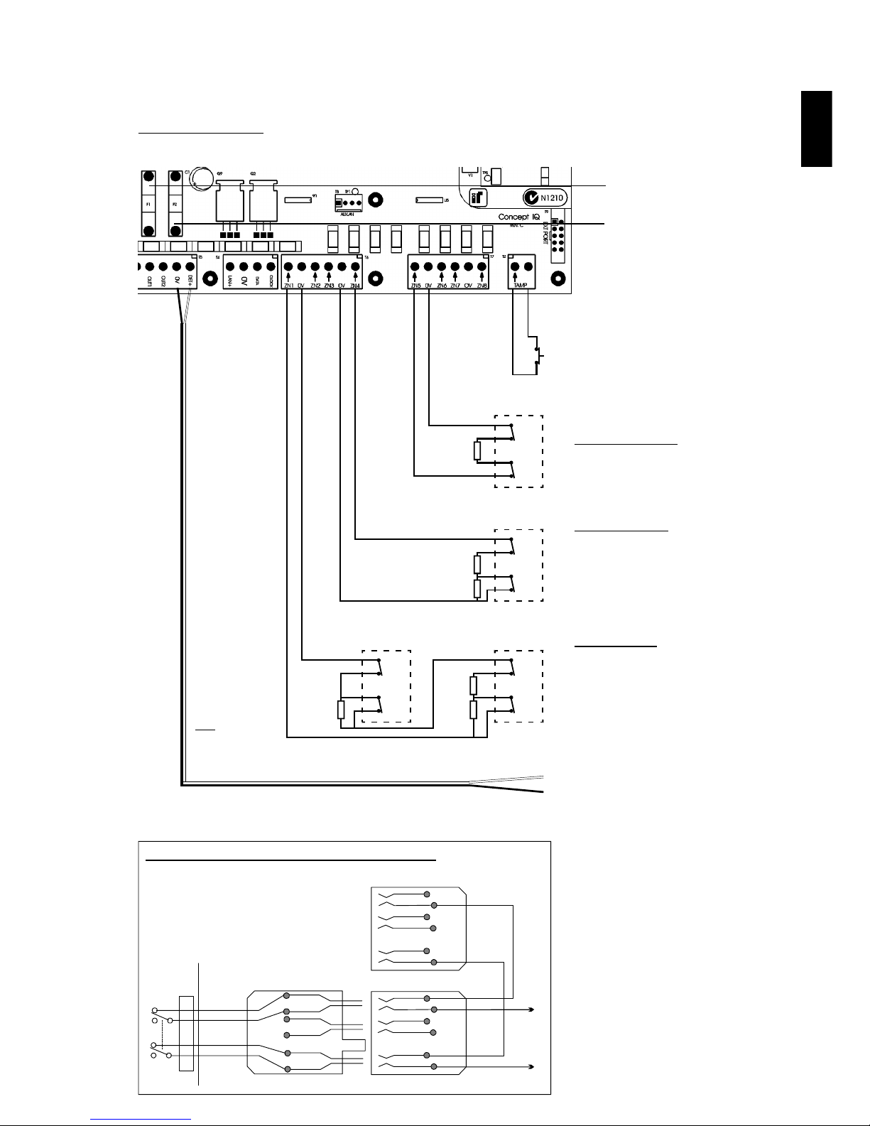
T2. “TAMP”. Dedicated Cabinet Tamper
input. Tamper switch supplied.
No End-of-line resistors necessary.
T6 and T7. Zone Input connections.
Single End-of-Line.
e.g.
3k3 Seal
Open Cct: Alarm
Dual End-of-Line.
e.g.
3k3 Seal
10k1 Alarm
Open Cct: Tamper
Short Cct: Tamper
Zone Doubling.
1k Seal
4k3 1st Zone in Alarm
7k8 2nd Zone in Alarm
11k1 1st & 2nd Zones in Alarm
Open Cct: Tamper
Short Cct: Tamper
T5. “DET+” and “0V”.
Detector Power connections.
12V Supply for Detectors and Auxiliary
Devices. Total combined current sourced
from “DET+” and “LAN+” must not exceed
600 milliAmps.
F1. Battery Input Fuse. 1A. M205.
Connection Details. Detectors, Tamper switch and Fuses
Minimum Cable spec: 14/0.2
Tamp.
Alarm
Detector
C
NC
C
NC
EOL Res.
3k3 Typ.
Tamp.
Alarm
Detector
C
NC
C
NC
EOL Res.
3k3 Typ.
6k8 Typ.
Tamp.
Alarm
2nd Detector
C
NC
C
NC
EOL
1k
6k8
Tamp.
Alarm
1st Detector
C
NC
C
NC
EOL
3k3
PSTN
Line
604 Socket
to other equipment.
604 Cable from
Concept IQ
(Supplied)
Mode 3 Telephone Socket Wiring for Australia
F2. PWR Fuse. 1A. M205.
1
2
3
4
1
2
3
4
5
6
5
6
1
2
5
6
3
4
JP9
Control
Module
1
2
5
6
NOTE: Zone Input connections.
“Normally Open” Alarm Contacts.
Normally Open Alarm Contacts (e.g. As
often found on Smoke Detectors) are
wired in the same manner as Normally
Closed contacts.
When programming the Zone Input,
Option 8 (“Normally Open”) in the “Zone
Options” must be selected. (Addresses
752 [Zone 1] to 767 [Zone 16] )
Control Module. Version 1.02
NOTE:
The 1k EOL
Resistor must
be fitted at the
2nd Detector.
Page 8
Section 1. Installation. CONCEPT IQ. Installation & Programming Manual.p6
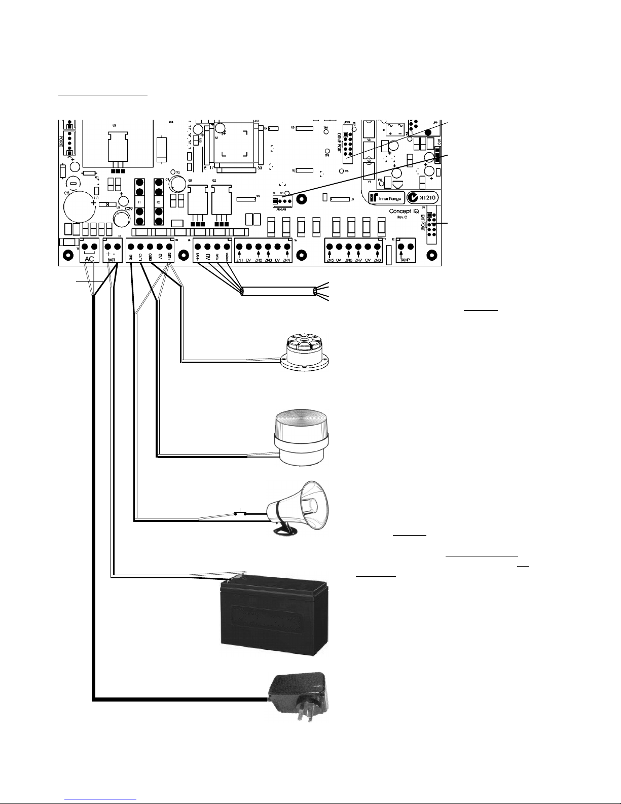
T1. “AC”.
16V AC Input.
(Connect Green/Yellow Earth wire to T3 “-”)
T4. LAN connections to Terminals. (Up to 4)
Maximum run to furthest LAN Module: 100m.
Total LAN cabling: 150m maximum.
If twisted pair cable is used, DO NOT
combine “Clock” & “Data” on the same pair.
T9. Zone Input /
Auxiliary Output
Expansion Bus Port.
T3. “+” & “-”.
12V Sealed Lead Acid Battery connection.
Maximum Battery capacity: 7 AH
T5. “SPK” & “DET+”
Siren Speaker output.
Maximum load: 8 Ohms
Minimum Speaker rating: 10 Watts.
(i.e. 1 x 8 Ohm Speaker only. Additional
speakers must not be connected in parallel)
NOTE: A 6k8 Resistor must be connected
between “SPK” & “DET+” if Siren speaker not
connected.
T5. “OUT1” & “DET+” (Strobe)
Auxiliary 1 Output.
Normally used for Strobe.
Maximum switched current: 200 mA.
T5. “OUT2” & “DET+”.
Auxiliary 2 Output. General purpose Aux.
May be used for Piezo Siren.
(Program Aux 2 as Event Type 59)
Maximum switched current: 200 mA.
Minimum Cable spec: 14/0.2
Minimum Cable spec: 14/0.2
Minimum Cable spec: 14/0.2
Battery cable supplied.
4 Core Security Cable
recommended. (14/0.2)
CAUTION:
Total current sourced from
“DET+” and “LAN+” must not
exceed 600mA.
Connection Details. Power, Warning devices & LAN
T8. “Aux LAN”.
For temporary
connection of a
Terminal for
diagnostic purposes.
Siren cover Tamper
switch (Normally Closed)
Disclaimer: 1. The manufacturer &/or it’s agents take no responsibility for any damage, financial loss or injury caused to any equipment, property or
persons resulting from the correct or incorrect use of the system or it’s peripherals. The purchaser assumes all responsibility in the use of the system
and it’s peripherals.
2. While every effort has been made to ensure the accuracy of this manual, the manufacturer assumes no responsibility or liability for any errors or
omissions. Due to ongoing development, this manual is subject to change without notice.
JP10. DTMF/Voice
Card Port.
Earth
(Grn/Yell)
Page 9
CONCEPT IQ. Installation & Programming Manual.
Install
p7
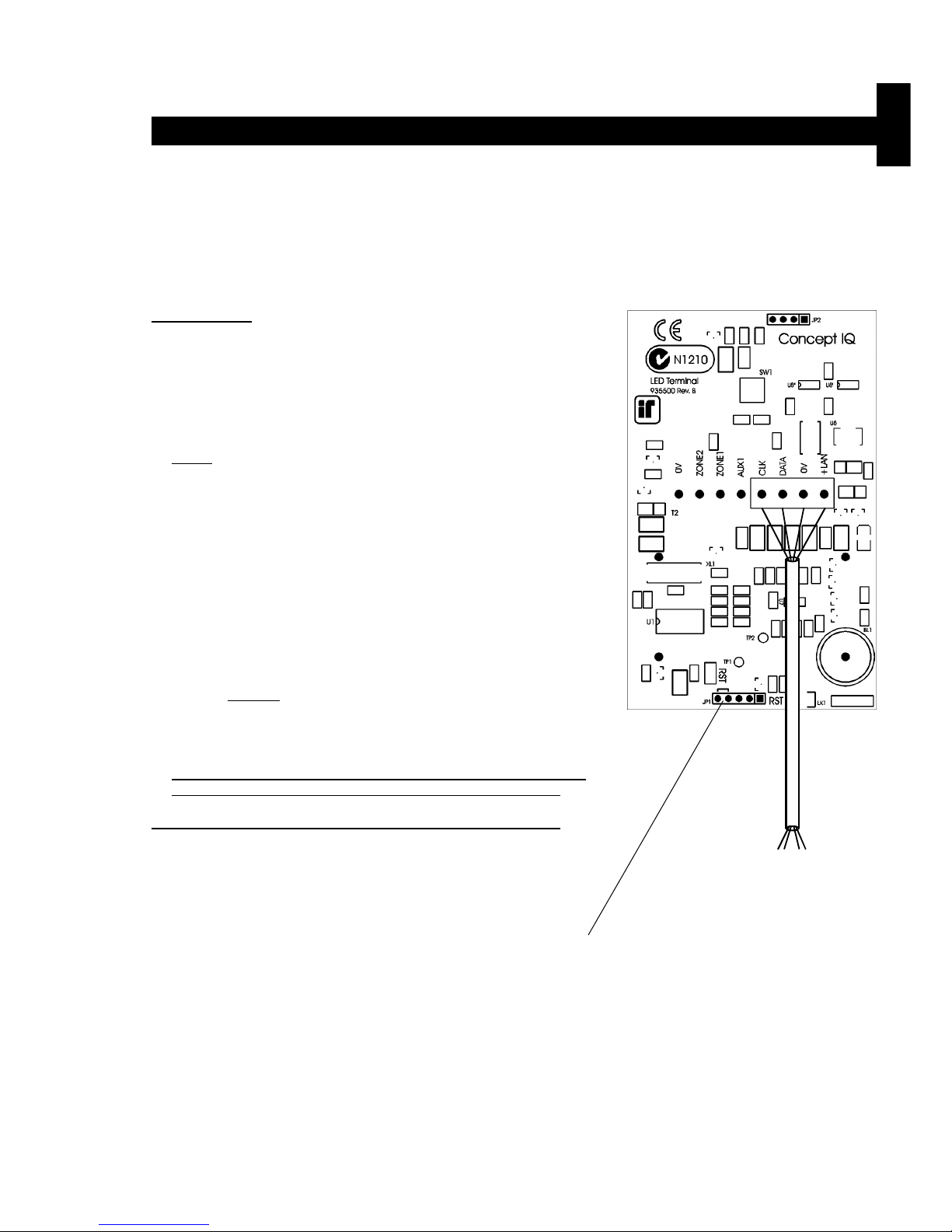
Standard LED Terminal. 995500
© 2001. Inner Range Pty. Ltd. Part No: 635500
The LED Terminal is the main operator interface for the Concept IQ system.
The Terminal provides status display of 16 Zone Inputs and 4 Areas along with indication of “Power”, “Fault”, “Home Mode”
and “Armed” conditions. Audible button press feedback is provided and the built-in Beeper also provides indication of
Alarms, Entry/Exit warnings, Auto-Arm warning, User Operation OK and User Operation Unsuccessful.
While the system can be programmed via Upload/Download software, the LED Terminal also provides the ability for the
Installer to program all system parameters.
LAN connections to the Control
Module T4 connector.
4 Core
Security Cable
recommended.
(14/0.2)
INSTALLATION.
Mounting the Terminal.
- The Terminal must be installed on a flat, vertical surface in an
appropriate location. Ensure that the display will be at, or slightly
below eye level, for all Users.
- Remove the rear mounting plate from the back of the Terminal.
- Cut suitable holes in the mounting surface for cable entry and the
fasteners. (The rear mounting plate can be used as a template)
NOTE: The Terminal is also designed to be mounted on plasterboard/
gyprock surfaces using a standard switch plate Mounting Clip. e.g.
Clipsal 154 or HPM 712. (84mm mounting centres)
- The rear mounting plate can now be installed using appropriate
fasteners through the holes provided. Remember to insert the LAN
cable and any other wiring through the cable entry cutout first.
- Connect the wiring into the Screw Terminal block T2.
- Clip the Terminal onto the rear mounting plate by first locating the
tongue at the top of the Terminal into the slot provided by the rear
mounting plate, then clip the bottom of the Terminal into place.
LAN connection. A maximum of 4 LAN Modules can be connected to
the system LAN. The LAN must be connected as follows:
- Recommended cable is 4 core or 6 core security cable 14/0.20.
(NOT twisted pair. Twisted pair cable [e.g. Category 5] may be used,
however, DO NOT combine “Clock” & “Data” on the same pair)
- Do not apply power to cable until all connections are made & checked.
- Maximum cabling distance from the Control Module to the furthest
Module must not exceed 100 metres.
- Maximum total LAN cabling in the system must not exceed 150 m.
- DO NOT connect the “CLK” & “DATA” wires to the Control Module until
all LAN Modules (e.g. Terminals) are Commissioned. (See below)
ADDRESSING & COMMISSIONING (Read “LAN connection” first)
1. Enable Terminal Configuration Mode.
Method 1: -Remove power from the Terminal.
-Hold down the <NEXT> and <HOME> keys.
-Re-apply power to the Terminal.
-Release the <NEXT> and <HOME> keys.
Method 2: -Hold down the <NEXT> and <HOME> keys.
-Short the “RST” (Reset) link on the rear of the Terminal.
-Release the <NEXT> and <HOME> keys.
2. Note the current Address setting. The current Address of the Terminal will be displayed via the Zone 1 to 4 Lamps.
The Zone Lamp number that corresponds to the current Address will flash.
3. Select the new Terminal Address number.
-Press the key that corresponds to the required Address (1 to 4) within 10 seconds, then press <ENTER>.
-When the <ENTER> key is pressed, the Terminal will exit Terminal Configuration Mode.
4. Initialize the LAN. If a new Terminal is added to an existing system, once the Terminal is configured and connected to
the system LAN, the LAN must be initialized by Removing and Re-applying power to the Control Module.
Remember to disconnect the battery also when removing power.
5. Area Assignment. Additional system programming allows Terminals to be configured for Single Area or Multi-Area
Mode (Address 961), and an “Associated Area” to be defined for each Terminal (Addresses 952 to 955).
Standard LED Terminal. Version 1.01
Page 10
Section 1. Installation. CONCEPT IQ. Installation & Programming Manual.p8
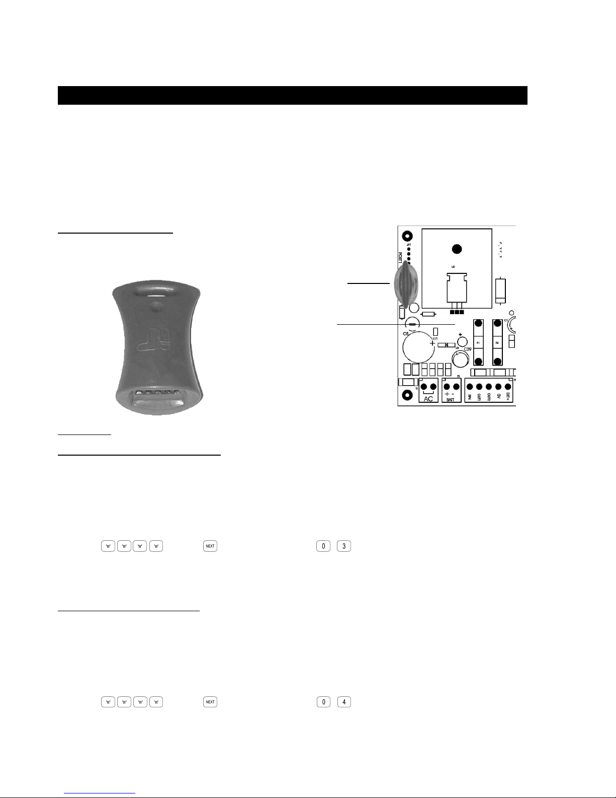
Programming Key. 995510
Programming Key Parts List
- Programming key.
- Instruction Manual. (This document)
The Concept IQ Programming Key is a portable non-volatile memory device housed in a convenient “key tag”.
The Programming Key connects directly to the Control Module Port 0 and allows the Installer to Upload the system
database from the Control Module, or Download a system database to the Control Module via a simple key press
sequence on the LED Terminal.
An indicator lamp is provided on the Programming key to monitor data transfer activity, and the LED Terminal provides
audible indication of Upload/Download Successful/Failed.
OPERATION.
Importing Data from the Programming Key.
This Mode allows the Installer to copy the programming contents of the Programming Key into the Control Module.
IMPORTANT NOTE: The new data will override the existing contents of the Control Module memory.
Connect the Programming Key to Serial Port 0 on the Control Module.
Select the Import Data Mode:
Enter PIN; ... , then , then the Mode number; , .
The Lamp on the Programming Key will flash slowly to indicate data is being copied.
The Terminal beeper will sound 3 short beeps if the operation was successful, or 1 long beep if unsuccessful.
Export Data to the Programming Key.
This Mode allows the Installer to copy the programming contents of the Control Module into the Programming Key.
IMPORTANT NOTE: The Control Module data will override the existing contents of the Programming Key.
Connect the Programming Key to Serial Port 0 on the Control Module.
Select the Export Data Mode:
Enter PIN; ... , then , then the Mode number; , .
The Lamp on the Programming Key will flash quickly to indicate data is being copied.
The Terminal beeper will sound 3 short beeps if the operation was successful, or 1 long beep if unsuccessful.
© 2001. Inner Range Pty. Ltd. Part No: 635510
Programming Key
connected to Port 0.
Control Module
Version 1.00
Page 11

CONCEPT IQ. Installation & Programming Manual.
Install
p9
Enhanced LED Terminal. 995500EN
© 2001. Inner Range Pty. Ltd. Part No: 635500EN
The Enhanced LED Terminal is a versatile operator interface for the Concept IQ system providing standard LED Terminal
functions along with an interface for Door Access Control. The Terminal provides status display of a single “Associated”
Area and up to 16 Zone Inputs along with indication of “Power”, “Fault”, “Home Mode” and “Armed” conditions.
Audible button press feedback is provided and the built-in Beeper also provides indication of Alarms, Entry/Exit warnings,
Auto-Arm warning, User Operation OK and User Operation Unsuccessful.
While the system can be programmed via Upload/Download software, the Terminal also provides the ability for the Installer
to program all system parameters.
In addtion to these standard functions, the Enhanced Terminal also provides:
-Single low power open-collector Door Unlock Output. (Programmable un-lock time; 0 to 60 seconds)
-Two multi purpose inputs configurable as Wiegand Reader Data inputs and REX / Door Sealed.
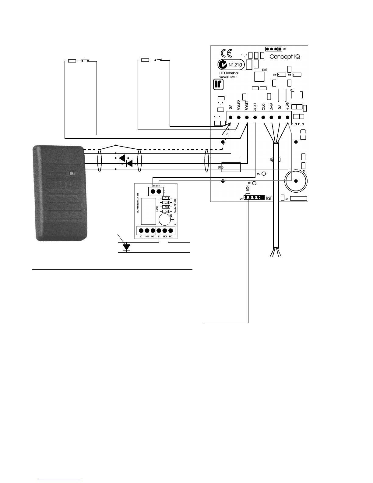
INSTALLATION. Connection diagrams provided on the next page.
Mounting the Terminal.
- IMPORTANT: Enhanced Terminals must be installed on the inside (secure side) of the Door to be controlled.
- The Terminal must be installed on a flat, vertical surface in an appropriate location. Ensure that the display will be at, or
slightly below eye level, for all Users.
- Remove the rear mounting plate from the back of the Terminal.
- Cut suitable holes in the mounting surface for cable entry and the fasteners. (The rear mounting plate can be used as a
template)
NOTE: The Terminal is also designed to be mounted on plasterboard/gyprock surfaces using a standard switch plate
Mounting Clip. e.g. Clipsal 154 or HPM 712.
- The rear mounting plate can now be installed using appropriate fasteners through the holes provided. Remember to
insert the LAN cable and other wiring through the cable entry cutout first.
- Connect the wiring into the Screw Terminal block T2.
- Clip the Terminal onto the rear mounting plate by first locating the tongue at the top of the Terminal into the slot provided by the rear mounting plate, then clip the bottom of the Terminal into place.
LAN connection. A maximum of 4 LAN Modules can be connected to the system LAN.
- Recommended cable is 4 core or 6 core security cable 14/0.20. (NOT twisted pair. Twisted pair cable [e.g. Category 5]
may be used, however, DO NOT combine “Clock” & “Data” on the same pair.)
- Do not apply power to cable until all connections are made and checked.
- Maximum cabling distance from the Control Module to the furthest Module must not exceed 100 metres.
- Maximum total LAN cabling in the system must not exceed 150 metres.
- DO NOT connect the “CLK” & “DATA” wires to the Control Module until all LAN Modules (e.g. Terminals) are
Commissioned. (See next page)
Wiegand Reader connection. Note: Supports 12V Reader power supply only. (No 5V supply option)
- The Reader “+”, “-”, “D1” & “D0” wires must be connected to “+LAN”, “0V”, “Zone1” & “Zone2” on the Terminal using
Shielded RS232 Data cable. e.g. Tycab DMC6702, Electra EAS7206, Belden 9536, Alpha 1296C, etc.
DO NOT use Twisted pair cable or Security cable under any circumstances.
NOTE: Check that there is sufficient current still available from the LAN power to supply the Reader. If not, a separate
power supply must be used for the Reader power.
- Diodes must be inserted in series with each of the D0 and D1 connections. Cathode to Reader.
Ensure that appropriate insulating sleeve is fitted over the Diodes and solder connections.
- Maximum cabling distance from the Reader to the Terminal must not exceed 80 metres.
Door Reed switch and Request to Exit button (REX) connections.
- The “Normally Open” Request to Exit (REX) button (if used) is connected between the “Zone 1” Input and “0V”. A 6k8
Resistor must be connected in series with the button.
- The “Normally Closed” Reed switch (if used) is connected between the “Zone 2” Input and “0V”. A 6k8 Resistor must be
connected in series with the Reed switch.
Lock Relay connection.
- The Lock power must be switched via a Relay to provide isolation from the Terminal circuits.
e.g. 995085 -1A DPDT Relay Board, or 995083S -2x10A Relay Board.
- The Relay control input is connected to “+” and “AUX1” on the Terminal.
- The power to the lock must be wired from a separate lock power supply, through the appropriate Relay contacts, and
must not make any connection to the Terminal wiring.
Enhanced LED Terminal. Version 1.02
Page 12
Section 1. Installation. CONCEPT IQ. Installation & Programming Manual.p10
LAN connections to
the Control Module
T4 connector.
4 Core
Security Cable
recommended.
(14/0.2)
ADDRESSING & COMMISSIONING (Read “LAN connection” first)
1. Enable Terminal Configuration Mode.
Method 1: -Remove power from the Terminal.
-Hold down the <NEXT> and <HOME> keys.
-Re-apply power to the Terminal.
-Release the <NEXT> and <HOME> keys.
Method 2: -Hold down the <NEXT> and <HOME> keys.
-Short the “RST” (Reset) link on the rear of the Terminal.
-Release the <NEXT> and <HOME> keys.
2. Note the current Address setting. The current Address of the Terminal will be displayed via the Zone 1 to 4 Lamps.
The Zone Lamp number that corresponds to the current Address will flash.
3. Select the new Terminal Address number.
-Press the key that corresponds to the required Address (1 to 4) within 10 seconds, then press <ENTER>.
4. Note the current Door Alarm enable status.
After the Terminal Address has been entered as per Step 3, the display will now show the current Door Alarm enable
status: 0 = Disabled (Default)
1 = Enabled
5. Enable / Disable Door Alarm.
If an Enhanced Terminal is required to generate a Door Alarm for Door Forced or Door Held conditions, then “Door
Alarm” must be enabled for that Terminal.
-To Enable or Disable, select the option required (0 or 1) within 10 seconds, then press <ENTER>.
-When the <ENTER> key is pressed, the Enhanced Terminal will now exit Terminal Configuration Mode.
6. Initialize the LAN. If a new Terminal is added to an existing system, once the Terminal is configured and connected
to the system LAN, the LAN must be initialized by Removing and Re-applying power to the Control Module.
Remember to disconnect the battery also when removing power.
7. Area Assignment. Enhanced Terminals must be configured for Single Area Mode (Address 961), and an “Associated
Area” must be defined for each Terminal (Addresses 952 to 955).
8. Door Un-lock time. The system has a default Door Un-lock time of 5 seconds. If a different time is required, this value
can be edited at Address 872.
Request to Exit (REX) button
(Normally Open)
EOL Res.
6k8
Door Reed Switch
(Normally Closed)
EOL Res.
6k8
Shield
0V Black
D0 Green
D1 White
+ Red
To Lock -
Strike +
- From Lock
+ Power Supply
*
1A DPDT Relay
Board. 995085
* Pwr to Lock: Use NC
Pwr to Unlock: Use NO
4 Core
Security Cable
recommended.
(14/0.2)
Shielded RS232 Data cable.
Fit reverse
Diode across
Lock coil.
Page 13
CONCEPT IQ. Installation & Programming Manual.
Install
p11
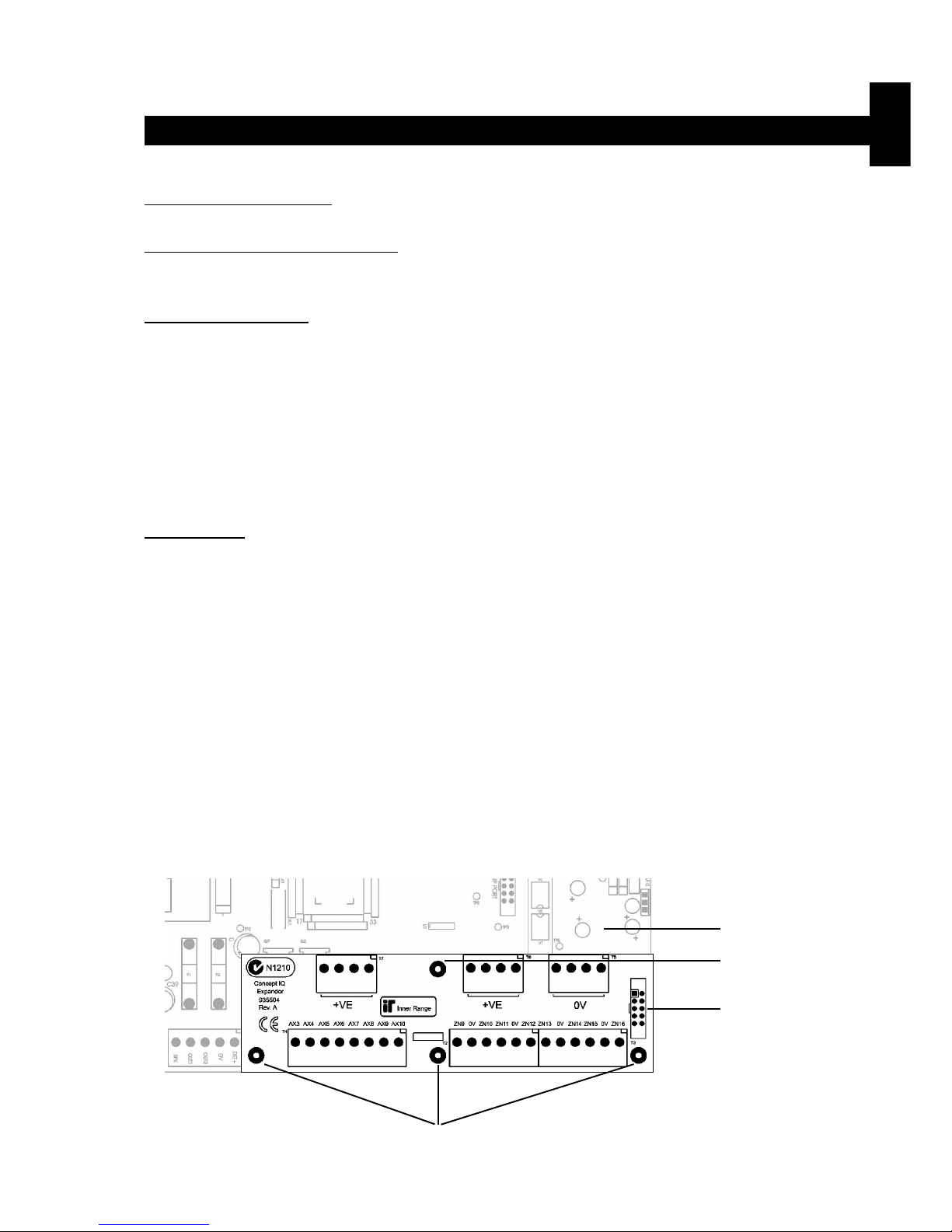
Expansion Card. 995503 / 995504
© 2001. Inner Range Pty. Ltd. Part No: 635504
Expansion Card Parts List
- Zone/Auxiliary Expansion Card.
- Installation Manual. (This document)
- Installation Kit containing:
- 3 x 20mm Brass PCB standoff.
- 1 x 20mm Threaded plastic PCB standoff.
- 1 x Pan Head M3x6mm screw.
- 2 x 6 Way plug-on screw terminals.
- 4 x 2 Way plug-on screw terminals.
- 10 x 3k3 End-of-line resistors. 8 x Zone Inputs, 2 x Spare. (orange-orange-black-brown-brown)
- 10 x 6k8 End-of-line resistors. 8 x Zone Inputs, 2 x Spare. (blue-grey-black-brown-brown)
The Expansion Card connects directly to the Control Module Expansion Port and is available in 2 Versions:
995503. Zone Expansion Card.
Provides 8 additional Zone Inputs and additional Detector power connections.
995504. Zone & Auxiliary Expansion Card.
Incorporates all Zone Expansion card features along with 8 additional low power open-collector Auxiliary Outputs and 4
additional +12V Auxiliary power outputs.
INSTALLATION.
- Remove all power to the Control Module. Remember to disconnect the Battery. See Note 1 below.
- Remove the 3 screws along the bottom edge of the Control Module PCB. (The screws adjacent to T4, T6 & T2)
- Fit the 3 Brass PCB standoffs in place of these 3 screws.
- Fit the Threaded plastic PCB standoff into the mounting hole on the Control Module PCB next to T8 (AUX LAN).
- Plug the Expander Card onto the box header T9 on the Control Module (“EXT PORT”).
- Secure the Expander Card to the 4 standoffs using the 3 screws removed from the Control Module and the additional
screw provided in the Installation kit.
- Connect the additional Zone Inputs and/or Auxiliary Outputs required.
- Reconnect the power and the Battery to the Control Module, then program the required Zones and Auxiliaries.
NOTES: 1) CAUTION: Shorting any of the pins on the Expansion Port connector whilst powered up, can result
in permanent damage to the Control Module and/or the Expansion Card.
2) Zone Doubling CANNOT BE USED on the system when an Expander Card is fitted.
See next page for Zone Input & Auxiliary Output wiring.
Location of Brass
PCB standoffs
Control Module.
Location of Threaded
plastic PCB standoff.
Expansion Port.
T9. “EXT PORT”.
Expansion Cards. Version 1.00
Page 14
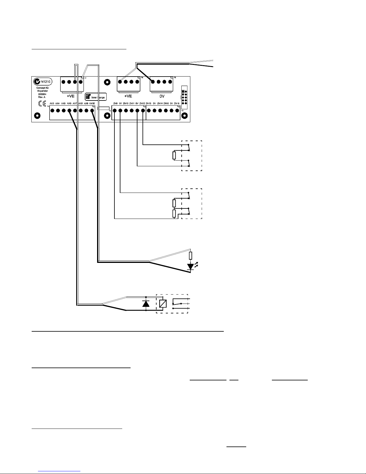
Section 1. Installation. CONCEPT IQ. Installation & Programming Manual.p12
T2 and T3. Zone Input connections.
Single End-of-Line.
Dual End-of-Line.
T5 & T6. “+VE” and “0V”.
Detector Power connections.
12V Supply for Detectors.
Total combined current sourced from
“DET+” and “LAN+” on the Control
Module, and “+ve” on the Expander Card
must not exceed 600 milliAmps.
Minimum Cable spec: 14/0.2
Tamp.
Alarm
Detector
C
NC
C
NC
EOL Res.
3k3 Typ.
Tamp.
Alarm
Detector
C
NC
C
NC
EOL Res.
3k3 Typ.
6k8 Typ.
T4. Auxiliary Output connections.
995504 Only.
LED wiring.
(Note. Dropping Resistor can be any
value in the range of 1k to around 1k5.
e.g. 2 x 3k3 Resistors in parallel)
Relay wiring.
Relay coil voltage: 12V DC
Fit reverse diode across coil.
e.g. 1N4001 - 1N4004.
1k min.
Relay
NC
O
NO
EXPANDER CARD WIRING DIAGRAMS.
IMPORTANT NOTE. AUXILIARY POWER:
Total combined current sourced from “DET+” and “LAN+” on the Control Module, and “+ve” on the Expander Card
must not exceed 600 milliAmps.
If additional current is required, a separate, external Power Supply and backup battery must be used to provide power to
the required Auxiliary devices and/or Detectors.
e.g. 994051 2A Power Supply.
994055 Short-form Power Supply Board + 560001 Plug pack (For 1A PS), or 560004 In-line transformer (For 2A PS)
When a separate Power Supply is used:
1) The Power Supply must be installed close to the Control Module, and the 0V (or “-VE”) supply connections of the
Power Supply and the Control Module must be connected together using a heavy guage wire. (14/0.20 minimum)
2) The “+ve” supply connections of any system Module (“DET+”, “LAN+” or “+VE”) must not be connected to +ve of the
separate Power Supply.
NOTE: ZONE INPUT CONNECTIONS. “NORMALLY OPEN” ALARM CONTACTS.
Normally Open Alarm Contacts (e.g. As often found on Smoke Detectors) are wired in the same manner as Normally
Closed contacts. When programming the Zone Input, Option 8 (“Normally Open”) in the “Zone Options” must be selected.
(Addresses 752 [Zone 1] to 767 [Zone 16] )
Page 15
CONCEPT IQ. Installation & Programming Manual.
Install
p13
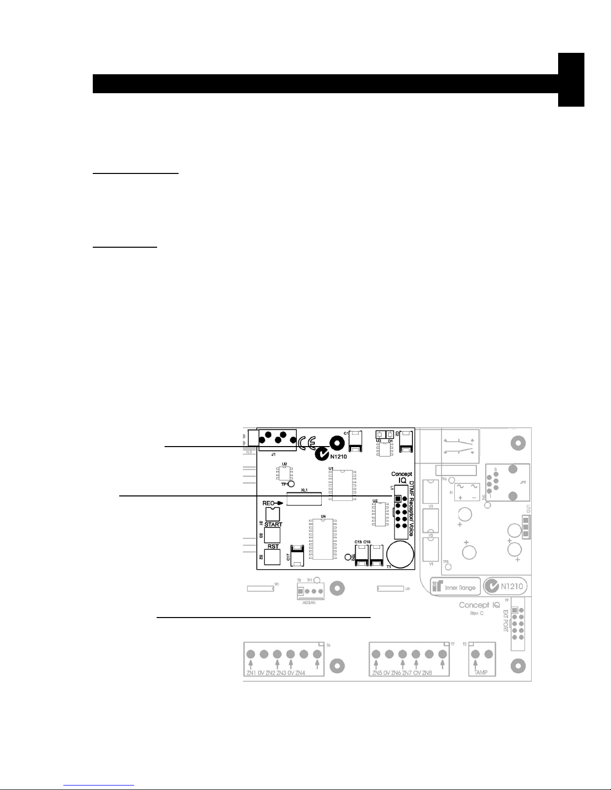
DTMF Card. 995505
© 2001. Inner Range Pty. Ltd. Part No: 635505
INSTALLATION.
- Remove the screw on the top edge of the Control Module PCB next to the STATUS Lamp.
- Fit the Brass PCB standoff in place of the screw.
- Plug the DTMF Card onto the box header JP10 on the Control Module (“DTMF PORT”).
- Secure the DTMF Card to the standoff using the screw removed from the Control Module.
- Program the required DTMF functions. See Installation & Programming Manual, Section 10: Communications.
DTMF Card Parts List
- DTMF Card.
- Installation Manual. (This document)
- 1 x 20mm Brass PCB standoff.
The DTMF Card connects directly to the Control Module DTMF Port to provide Telephone remote control.
Location of Brass
PCB standoff.
JP10.
“DTMF PORT”.
Control Module.
DTMF Card. Version 1.00
Page 16

Section 1. Installation. CONCEPT IQ. Installation & Programming Manual.p14
This page intentionally left blank.
Page 17

Section 2. Intro. Version 1.01 p1CONCEPT IQ. Installation & Programming Manual.
Intro
SECTION 2.
INTRODUCTION TO PROGRAMMING.
1. Introduction
1.1 System Overview .............................................................................................. 2
1.2 Types of Users..................................................................................................3
1.3 Default Users .................................................................................................... 3
2. The LED Terminal
2.1 Key Functions ................................................................................................... 4
2.2 Beeper Indications............................................................................................. 4
2.3 Lamp Indications ............................................................................................... 5
3 Installer Modes
3.1 Overview........................................................................................................... 6
3.2 Accessing the Installer Modes ........................................................................... 6
3.3 Mode 01. Programming Mode...........................................................................7
3.4 Mode 02. Defaulting Mode ................................................................................ 7
3.5 Factory Default Database settings .................................................................... 8
3.6 Mode 03. Import Data from Programming Key .................................................. 9
3.7 Mode 04. Export Data to Programming Key ......................................................9
3.8 Mode 05. Terminal Area Programming..............................................................9
4 Programming Techniques
4.1 The System Database ....................................................................................... 10
4.2 Selecting and Programming the Data.................................................................10
4.3 Example of Programming ..................................................................................11
5 Types of Data
5.1 Overview........................................................................................................... 12
5.2 “Value” Data......................................................................................................12
5.3 “Options” Data................................................................................................... 13
6 Recommended Programming Sequence .................................................................. 14
Contents
Page 18

p2 Section 2. Intro. Version 1.01 CONCEPT IQ. Installation & Programming Manual.
1. Introduction
1.1 SYSTEM OVERVIEW
The Concept IQ is an affordable, simple to use security system targeted at the domestic and small commercial
markets. The system has been designed for ease of use by the Installer and the End User.
System Hardware
The basic Control Module has the following hardware dimensions:
• Zones: 8 standard Zone Inputs or 16 doubled Zone Inputs.
• Auxiliaries: Total of 3. 1 Siren speaker / 1 Strobe / 1 General purpose.
• Serial Communications Port: RS232.
• External Device Bus.
• System LAN: Provides connectivity for up to 4 LAN Devices.
• IO Expansion Bus.
• Separate Tamper Input.
A variety of Peripheral devices can be connected directly to the Control Module:
• Programming Key.
• Plug-on Expansion Card options. 8 additional Auxiliary outputs and/or 8 additional Zone Inputs.
• DTMF communications Card.
• DTMF + Voice communications Card.
• Serial Adapter Cable for connection to PC.
The System LAN supports the following LAN Modules:
• Standard 16 Zone / 4 Area LED Terminal.
• Enhanced 16 Zone / 4 Area LED Terminal incorporating Input for a Wiegand Reader
and Input/Output facilities for access control functions.
• RF Terminal that adds 2 key or 4 key radio remote functionality.
Functional Description
Zone Inputs. Zone Inputs are individually programmed to define how they are to be processed. An appropriate
“Zone Type” is chosen and additional options relating to; Alarm Processing, Reporting, Siren,
Pulse counting, Testing, and type of Input Device can also be defined.
Global Zone options also allow system-wide parameters to be set for Pulse Counting, End-Of-Line
Resistor values and Zone Self Testing.
System Inputs. 20 System Inputs are also available for monitoring Faults and System Alarms such as; Power
Problems, Cabinet & Siren Tampers, Communication Problems, LAN & Battery Fuses, Zone Selftest Status, Keypad Emergency Alarms (Panic, Fire, Medical & Duress) and Access Control
violations. The Installer enables the Siren and Reporting options for each System Input required.
Automatic Battery Testing is available and triggers the Low Battery alarm if the test fails.
Areas. The system can be configured in Single Area or Multi Area Mode according to the site
requirements. Up to 4 Areas are available and Zone Inputs can be assigned to one or more Areas.
Each Area can be armed in “AWAY” or “HOME” modes.
Each LED Terminal can be configured for Multi-Area mode or assigned to a Single Area.
Siren. The Siren Speaker output supports a standard 8 Ohm Horn speaker and can generate 4 different
siren tones for Burglary, Fire, Medical & Panic alarms. The Siren time is programmable and any
System Input Alarms that are programmed to activate the Siren are differentiated from Zone Input
Alarms by a choice of 3 Siren tone-burst options.
Auxiliaries. Auxiliary outputs are extremely flexible thanks to a range of versatile programming options for
Security, Access control and Building/Home automation. A choice of over 50 “Auxiliary Types”
provides for Auxiliaries to; Annunciate different types of alarms, Indicate (mimic) individual Area or
Zone status, Indicate Entry, Exit, Auto-Arm & Zone Bypass conditions, Follow TimeZones, etc.
For each individual Auxiliary the output logic and On/Off actions can be tailored including an
optional timer that can be programmed in Minutes or Seconds.
Communications.The system offers “Contact ID” or “Domestic” dialing options. For a higher level of Dialer integrity a
Secondary telephone number can be programmed, Telephone line monitoring is provided and the
maximum number of dial attempts can be specified. A “Comms Fail” alarm is activated if the line is
Page 19

Section 2. Intro. Version 1.01 p3CONCEPT IQ. Installation & Programming Manual.
Intro
1.2 TYPES OF USERS
1.3 DEFAULT USERS:
The system has 3 special Users and 45 normal Users. The system can be configured for 4 digit or 6 digit PIN codes
depending on the requirements of the site. The normal Users can each be assigned a “User Type” and their “User
Areas” to define the items that they can control and the operations that they can perform.
Installer - User 1:
The Installer can perform all Installer operations, and all Master operations except for User programming and
Arming/Disarming. The Installer can only change their own PIN code. (Via Address 96. See Section 11: Users)
Master User - User 2:
The Master User can perform all the Master operations and has access to all Areas.
The Master operations include; Edit Users, View history, Walk test Zones, Set Real-time clock, Siren/Strobe/
Auxiliary Testing, Fault Analysis, View Software Version, Test Battery and Door Bell Enable/Disable.
The Master User can also perform all User operations. (This includes Arming / Dis-arming the system, Isolating
zones and Acknowledging alarms.)
The Master User automatically has permission to control all the Areas, Zones and Auxiliary outputs in the system.
These permissions cannot be changed for User 2.
Normal Users - User 3 to User 47:
Normal Users can perform a variety of operations such as Arming / Dis-arming , Isolating zones and Acknowledging
alarms with various levels of functionality as defined by the User’s “User Type”.
Any normal User can also be programmed as a Master User if required. In a Multi-Area system, a normal User
programmed as a Master User can only add a new User or edit existing Users who can access a subset of their own
Area list.
NOTE: DURESS CODES. A User PIN’s last digit + 1 will form a DURESS Code. e.g. If a user’s PIN is 1234, then
1235 will trigger a duress alarm, and if the user’s PIN is 1239, then 1230 will be a duress code.
tampered or the maximum attempts is reached. Daily, Weekly or Monthly Test reports can also be
sent at a specified time of day, or triggered manually by a Master User.
The Installer can dial in to the system from a PC for Upload/Download when required. Security is
provided by a PIN code requirement, and Callback and Fax Bypass options are available.
With the DTMF Card fitted, a User can dial in to the system, and using their PIN code, can perform
remote operations and obtain system status information.
On-board Serial Port is provided allowing connection of a Programming Key or PC for Upload /
Download.
Timers. An extensive range of Timers are provided catering for; Individual Area Exit/Entry delays, System
Siren time, Keypad lockout time and AC fail delay time. Four TimeZones are provided including
provision for up to 10 Holiday dates and automatic Daylight Saving adjustment is also catered for.
The TimeZones can be used to turn Auxiliaries On and/or Off and to control Areas.
User Functions. In addition to the User operations described in “Types of Users” below, the system provides a
number of options to simplify and/or enhance the User operations and feedback.
These include; Auto-Isolate on Arming, Quick Arming, Key-switch Arm/Disarm and Zone activity
display on LED Terminals.
The Default Installer PIN and Master PIN Codes should be changed as soon as possible after installation.
When choosing a new PIN Code, ensure that a PIN is chosen that will not be forgotten, while still providing security
against unauthorised access.
User Number Description Factory Default PIN code
User 1 Installer 2345 (or 234567)
User 2 Master User 0123 (or 012345)
User 3 to User 47 General Users (Can be programmed as a Master User) None
User 48 Reserved for system functions (e.g. Reporting Auto-arming etc.) Not applicable
Page 20
p4 Section 2. Intro. Version 1.01 CONCEPT IQ. Installation & Programming Manual.
2. The LED Terminal
2 or 3 Short Beeps: A User, Master or Installer function was successful.
1 Long Beep: A User, Master or Installer function has been unsuccessful.
When a wrong key is pressed, or an incorrect value/option is selected, the beeper tones
will sound at a lower pitch until a correct operation is successfully performed.
Continuous Short Beeps*: Entry Delay Timer, Exit Delay Timer or Auto-arm Warning.
*NOTE:
Single Area systems. All Terminals will beep in response to Exit delay, Entry delay or Auto-arm warnings.
Multi-Area systems. Only Terminals associated with a particular Area will beep in response to that Area’s
warning functions. IMPORTANT NOTE: Terminals not associated with an Area will only
beep on Area 1 warning functions.
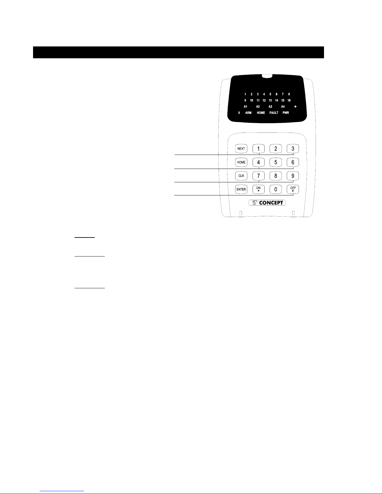
2.2 BEEPER INDICATIONS.
PANIC. Keys 1 & 3 pressed simultaneously.
FIRE. Keys 4 & 6 pressed simultaneously.
MEDICAL. Keys 7 & 9 pressed simultaneously.
REX (Request to Exit) <OFF> key.
Enhanced Terminals only.
2.1 KEY FUNCTIONS.
NEXT Installer:
-Select an Installer Mode. After entering the Installer PIN code, press <NEXT> then the Mode number.
-Used to view data values above a value of 16. Press <NEXT> to step through the digits.
Master User:
-Select a Master User operation. After entering the PIN code, press <NEXT> then the Mode number.
HOME -In Single Area Mode: Used to Arm the system in Home Mode.
-In Multi-Area Mode: Used to Arm the specified Area in Home Mode.
Master User:
-Used to step through programming Addresses when programming Users or Telephone numbers.
-Used to toggle between Zone Test modes.
CLR -Set the data in the current Address to the Factory Default. (Press <*>, <CLR>, <ENTER>)
-Clear the data already entered if you have made a mistake.
-Logoff the Terminal. (Exit the current Mode of operation)
ENTER -Selects the specified programming Address. (After the PIN Code and the Address number have been
entered)
-Saves the data entered in a programming Address.
AUTO-LOGOFF: The Terminal will automatically logoff the operator if there is no keypad activity detected for 30
seconds. This is to protect the system against unauthorised operator activity.
Page 21
Section 2. Intro. Version 1.01 p5CONCEPT IQ. Installation & Programming Manual.
Intro
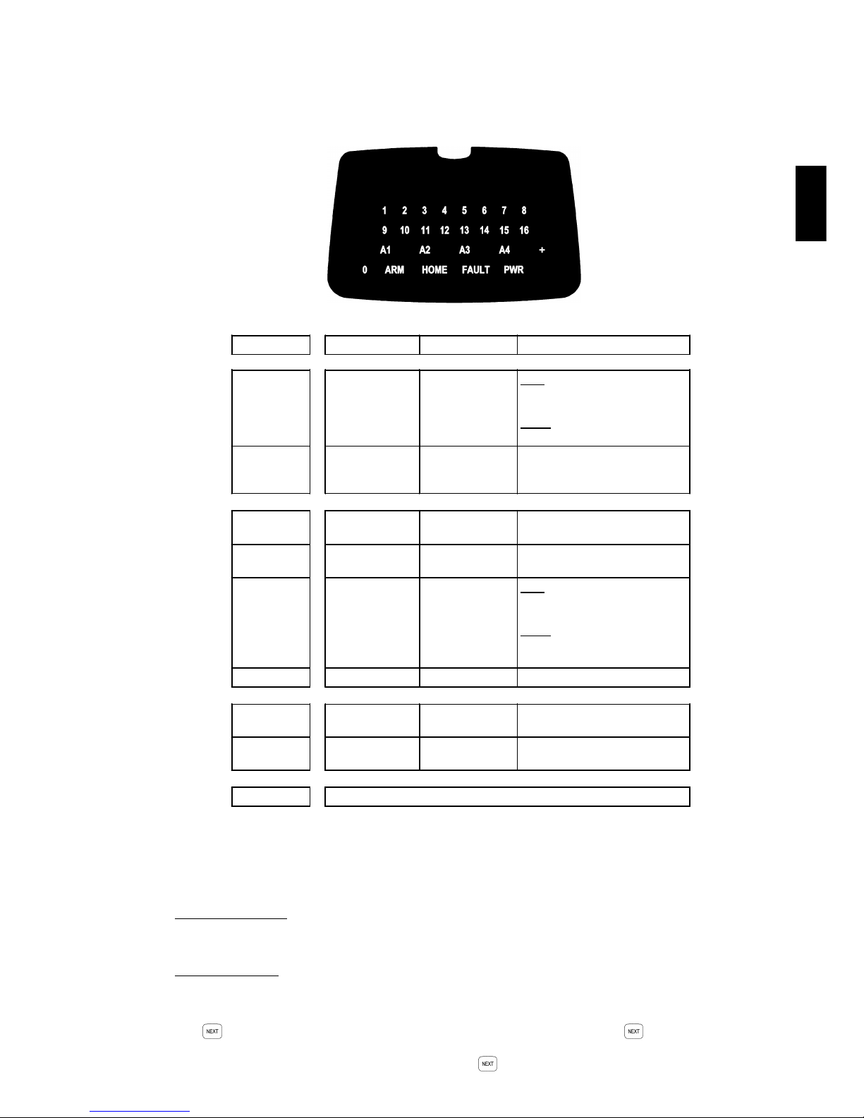
2.3 LAMP INDICATIONS.
2.4 DATA VALUE INDICATION VIA TERMINAL LAMPS.
Single digit numbers.
These are numbers between 0 and 16 and are displayed by the “0” Lamp and the Zone Lamps “1” to “16” on the
LED Terminal.
Multi digit numbers.
These are all other numbers ranging from 17 to 255.
These numbers are displayed one digit at a time by a sequence of flashing Lamps on the LED Terminal.
The “0” Lamp and the Zone Lamps “1” to “9” are used to display each digit in turn.
The key is used step through the digits. A short beep will sound each time the key is pressed to display
the next digit.
When the last digit in the sequence is displayed and the key is pressed again, a long beep will sound to
indicate that there are no more digits to display and the first digit will again be displayed.
Lamp ON OFF FLASHING
ZONE Lamps
1 to 16
When the Zone
is Un-sealed.
(If the "Zone
activity" option
enabled)
When the Zone
is Sealed.
FAST: *
When there has been an
Alarm / Tamper on the Zone.
SLOW: *
When the Zone has been Isolated.
AREA Lamps
A1, A2, A3, A4
Area is Armed.
(Multi-Area mode
only)
Area is Dis-armed. There has been an Alarm in the
Area.
(Multi-Area mode only)
ARM Area/s are armed
in normal mode.
System not armed
in normal mode.
-
HOME Area/s are armed
in home mode.
System not armed
in home mode.
-
FAULT § A system input is
currently in alarm *
No system inputs
are in alarm.
FAST: *
A system input has been in alarm
and must be acknowledged.
SLOW: *
When a System Input has been
Isolated.
PWR AC mains OK AC mains problem. -
ARM & HOME - - System is in "Isolate" mode.
(NEXT, 10)
FAULT & PWR - - System is in "Master Operations"
mode. i.e. NEXT functions.
0 Used to display values in programming mode.
NOTES: * Alarm indication takes priority over Isolate indication.
§ See "System Input Mapping and Functional Description" in Section 7.
Page 22

p6 Section 2. Intro. Version 1.01 CONCEPT IQ. Installation & Programming Manual.
3. Installer Modes
The Default Installer Code is 2345.
This Code should be changed as soon as possible after installation.
When choosing a new Installer Code, ensure that a PIN code is chosen that will not be forgotten, while still providing
security against unauthorised access.
Installer Operations require the Installer to Access a number of different Modes.
This is done by entering a valid Installer PIN code, then pressing the <NEXT> key before selecting the 2-digit Mode
number. e.g.
Enter PIN; ... , then , then the Mode number; ,
This key sequence must be used to access all the Operational Modes described in this section.
Remember that the <NEXT> “n”, “n” sequence must be preceded by the Installer PIN code.
e.g. To Enter Programming Mode:
Enter PIN; ... , then , then the Mode number; ,
NOTE: Upon entering Programming mode the first digit of the Primary Telephone Number at Address 16 will be
displayed.
The following pages provide full descriptions of each of the Installer Modes.
3.2 ACCESSING THE INSTALLER MODES.
In order to Program the system and perform other Installer operations, the Installer must access the appropriate
Installer Mode. There are 5 Installer Modes available.
Installer Modes and Mode Indication.
3.1 OVERVIEW.
Mode Mode Name LED Terminal Indication
01 Programming Mode <HOME>, <FAULT> and <PWR> Lamps flashing
02 Default the Control Module. <HOME>, <FAULT> and <PWR> Lamps flashing
03
Import system programming from Programming Key. 3 beeps when complete. Long beep if unsuccessful.
(Lamp on Prog. key flashes slowly during transfer)
04
Export system programming to Programming Key. 3 beeps when complete. Long beep if unsuccessful.
(Lamp on Prog. key flashes quickly during transfer)
05
Terminal Programming. <HOME>, <FAULT> and <PWR> Lamps flashing
Page 23

Section 2. Intro. Version 1.01 p7CONCEPT IQ. Installation & Programming Manual.
Intro
3.4 MODE “02”. DEFAULTING THE CONTROL MODULE.
Defaulting the Control Module allows the Installer to clear any current system programming from the Control Module
and select a factory default database to simplify the programming task.
The Default Database options can be divided into 3 main options:
Option 0: The Control Module memory is completely cleared with the exception of the Installer and Master
User Codes.
Options 1 to 16: The Control Module memory is defaulted to the Factory settings shown in the table on the following
page AND the number of Zones specified by the Option selected, are programmed into Area 1.
Option 49: The Master Code is defaulted to the Factory setting and all other programming is left intact.
CAUTION: Defaulting the Control Module will erase all current programming stored in the memory before
implementing any Factory default settings. (With the exception of Default Option 49)
Select the Defaulting Mode:
Enter PIN; ... , then , then the Mode number; ,
The <HOME>, <FAULT> and <PWR> Lamps on the LED Terminal will flash simultaneously.
Select the Default Option
Press , then the Default Option (1 or 2 digits), then
DEFAULT OPTIONS:
0: Database is completely cleared except for Installer & Master Codes.
1: Database is defaulted to Factory Default settings AND 1 Zone is programmed into the system.
2: Database is defaulted to Factory Default settings AND 2 Zones are programmed into the system.
3 to 15: Database is defaulted to Factory Default settings AND the specified number of Zones are programmed
into the system. i.e. 3 Zones to 15 Zones.
16: Database is defaulted to Factory Default settings AND 16 Zones are programmed into the system.
49: Master Code Default. Only the Master code is reset to the factory default. All other programming remains
unchanged.
NOTES:
1) The product is dispatched from the factory Defaulted with Option 8 (Factory Default settings and 8 Zones)
2) In Default Options 1 to 16, the Zones programmed into the system are assigned to Area 1.
3) If Default options 9 to 16 are used, and Zones 9 to 16 are added using Zone Doubling (i.e. Not via an
Expander card), the “End-of-Line Resistor value” (Address 786) must be set to Type 14 - Zone Doubling.
Exit from Defaulting Mode
Press to exit.
Reset the Control Module:
Disconnect the AC Input and the Battery from the Control Module, then re-connect.
This mode allows the Installer to program all of the system data and options.
To Select Programming Mode:
Enter PIN; ... , then , then the Mode number; , .
See “Basic Programming Techniques” and “Types of Data” for more details of Programming Mode.
3.3 MODE “01”. PROGRAMMING MODE.
HARDWARE DEFAULT PROCEDURE.
The system can also be set to the Factory Default settings (Same as Default Option 8) via a hardware procedure.
- Disconnect the battery and remove power from the Control Module.
- Place a short circuit across Pins 2 & 3 of JP8 on the Control Module.
- Re-apply power to the Control Module and reconnect the battery.
- Remove the short circuit on JP8.
Page 24

p8 Section 2. Intro. Version 1.01 CONCEPT IQ. Installation & Programming Manual.
3.5 FACTORY DEFAULT DATABASE SETTINGS.
ADDRESS FUNCTION SETTING
16 and 32 Primary & Secondary Telephone Nos No numbers programmed
48 Reporting Format 0. None
49 Dialer options No options selected
50 Maximum attempts 10
51 to 53 Test Report Times No settings
54 Remote connect options 0. No Remote Connect
64 Callback Telephone Number No number programmed
80 Rings to Answer 16
81 Answering machine bypass 0. Disabled
82 Port 0 Comms Tasks 0. None
83 Port 0 Baud Rate 3. 9600
736 Zone Type. Zone 1 1. Delayed. (If Default Options 1 to 16 are selected)
737 Zone Type. Zone 2 2. Handover. (If Default Options 2 to 16 are selected)
738 to 751 Zone Type. Zone 3 to 16 as selected. 0. Instant. (If Default Options 3 to 16 are selected)
752 to 767 Zone Options No options selected.
768 to 783 Zone Area The number of Zones selected in the Default option are assigned to Area 1.
784 & 785 Max Pulse count & Pulse Time 0.
786 End-of-Line Resistor Type 3. Single End-of-line. 3k3
787 Self Test Period 0.
788 Siren Time 5 Minutes
789 Keypad Lockout Time 60 Seconds.
790 to 794 TimeZone 1 9:00 to 17:00. Monday to Friday
795 to 799 TimeZone 2 9:00 to 13:00. Saturday and Sunday
800 to 804 TimeZone 3 7:00 to 20:00. All days including Holidays. (Daytime)
805 to 809 TimeZone 4 20:00 to 7:00. All days including Holidays. (Night-time)
810 AC Report Delay Time 0
816 Auxiliary 1 Event Type 1. Burglary Alarm
817 to 825 Auxiliary 2 to 10 Event Type 0. None
832 to 841 Auxiliary 1 to 10 Time 0
848 Auxiliary 1 Response 2 & 3 Selected. On/Off when Event goes Valid/Invalid (Strobe Output)
849 to 857 Auxiliary 2 to10 Response 2 & 3 Selected. On/Off when Event goes Valid/Invalid
864 Spare
865 to 867 System Input Programming No settings programmed
868 General Options Options 4 & 8 selected. AC Mains sync & Zone activity display on Terminals
869 Emergency Options No options selected
870 & 871 Auto-Arm Timers 0.
872 Door Unlock Time 5 Seconds.
896 to 908 Area Client Codes No codes programmed
928 to 931 Area 1 to 4 Entry Delay Time Area 1: 30 Seconds. Area 2 to 4: 0 Seconds
936 to 939 Area 1 to 4 Exit Delay Time Area 1: 60 Seconds. Area 2 to 4: 0 Seconds
944 to 947 Area Arming Options No options selected
952 to 955 Terminal Associated Area No settings programmed
960 Multi Area Options No options programmed
961 Terminal Area Mode No options programmed
962 Spare
966 to 985 Holidays No Holiday dates programmed
986 & 989 Daylight Saving Start Month & End Month 0. Automatic Daylight Saving adjustment Disabled
987 & 990 Daylight Saving Start Week & End Week 5. Last Week of the Month
988 & 991 Daylight Saving Start Day & End Day 1. Sunday
Page 25

Section 2. Intro. Version 1.01 p9CONCEPT IQ. Installation & Programming Manual.
Intro
Terminal Programming allows the Installer to define which Area is to be associated with the LED Terminal.
NOTE: This Mode is only available if the Terminal is programmed for Multi-Area mode. (Address 960. Option 1
must be Selected)
Select the Terminal Programming Mode:
Enter PIN; ... , then , then the Mode number; ,
Select the Terminal Area Mode: (Not relevant to Enhanced Terminals which cannot be set to Multi-Area)
Press to Set the current Terminal to Single Area Mode.
Press to Set the current Terminal to Multi Area Mode.
Note that this operation will Edit the relevant option in Address 961, Terminal Area Mode.
When Single Area Mode is selected, the default “Associated Area” is Area 1 (General Area)
Select the Associated Area: (Single Area Mode must be selected in the previous step)
To select the Associated Area for the current Terminal, press the number (1 to 4) of the Area.
The Area selected will be displayed on the Area Lamps.
A long beep will sound if the terminal is not in Single Area Mode or the wrong key is pressed.
Note that this operation will Edit the data in the relevant Addresses 952 to 955, Terminal 1 to 4 Associated Area.
Press to exit Terminal Programming Mode.
3.6 MODE “03”. IMPORT DATA FROM THE PROGRAMMING KEY.
3.7 MODE “04”. EXPORT DATA TO THE PROGRAMMING KEY.
The Programming Key.
The Concept IQ Programming Key is a portable non-volatile memory device housed in a convenient “key tag”.
The Programming Key allows system programming to be uploaded from the Control Module or downloaded to the
Control Module by simply inserting the Programming Key into Serial Port 0 and performing a simple key sequence
on the LED Terminal.
A built-in Lamp on the Programming Key visually indicates when data transmission is active.
Importing Data from the Programming Key.
This Mode allows the Installer to copy the programming contents of the Programming Key into the Control Module.
IMPORTANT NOTE: The new data will override the existing contents of the Control Module memory.
Connect the Programming Key to Serial Port 0 on the Control Module.
Select the Import Data Mode:
Enter PIN; ... , then , then the Mode number; , .
The Lamp on the Programming Key will flash slowly to indicate data is being copied.
The Terminal beeper will sound 3 short beeps if the operation was successful, or 1 long beep if unsuccessful.
This Mode allows the Installer to copy the programming contents of the Control Module into the Programming Key.
IMPORTANT NOTE: The Control Module data will override the existing contents of the Programming Key.
Connect the Programming Key to Serial Port 0 on the Control Module.
Select the Export Data Mode:
Enter PIN; ... , then , then the Mode number; , .
The Lamp on the Programming Key will flash quickly to indicate data is being copied.
The Terminal beeper will sound 3 short beeps if the operation was successful, or 1 long beep if unsuccessful.
3.8 MODE “05”. TERMINAL AREA PROGRAMMING.
Page 26

p10 Section 2. Intro. Version 1.01 CONCEPT IQ. Installation & Programming Manual.
To Select the Data to be Viewed or Edited.
When in programming mode, the Memory Address to be viewed or edited can be selected by the following key
sequence:
Press , then the Address ... (2 or 3 digits - 16 to 988), then
Pressing will take you to the next Address.
(This does not apply to Data programmed in sequential Addresses such as PIN codes, Telephone Numbers and
Client codes)
The programming details of each Data Address in the following sections of this manual will only show the actual
Address number (nn...). Remember that the Installer must first access Programming Mode; and the Data Address
Number must be preceded by the <OFF / #> key.
To Edit the Data.
The Data Value at this Address will then be displayed on the Terminal, and can be changed by the following key
sequence:
Press , then the new Data Value or Option setting ... (1 to 16 digits*), then
* Depending on the type of Data required.
To set the Data in the current Address to the Factory Default setting:
Press , then , then
If you make a mistake while entering a value, press and enter that value again followed by the key.
Exiting the Installer Operations.
Press to exit any of the Installer Operations.
4.2 SELECTING AND PROGRAMMING THE DATA.
4. Programming Techniques
4.1 THE SYSTEM DATABASE.
The system programming is stored in Memory Addresses numbered 16 - 988.
Programming the system involves three steps:
1) Enter Programming Mode.
Then for each item of Data to be programmed;
2) Select the Memory Address to be programmed.
3) Program the new Data Value or Options for that Address.
Page 27

Section 2. Intro. Version 1.01 p11CONCEPT IQ. Installation & Programming Manual.
Intro
4.3 EXAMPLE OF PROGRAMMING.
This example shows how Zone 1 would be changed to the “Hand-over” Input Type.
Zone 1 Input Type is stored in Address 736.
STEP 1. Enter programming mode.
Enter Installer PIN code; ... , then , then the Programming Mode number; ,
STEP 2. Enter the Address to be changed.
Press , then the Address , then
STEP 3. Enter the new Data Value.
Press , then the new Data Value , then
(0 = Instant, 1 = Delayed, 2 = Handover, 3 = 24Hr Burglary, etc.)
STEP 4. Repeat Steps 2 and 3 to perform any additional programming required.
Press , to advance to the next Address. (i.e. Address 737 in this example)
OR
Press , then the new Address ... , then
Enter the new Data Value as before.
STEP 5. Exit the programming mode.
Press
Page 28

p12 Section 2. Intro. Version 1.01 CONCEPT IQ. Installation & Programming Manual.
5. Types of Data
5.2 “VALUE” DATA.
The range of Data values that can be stored in a Value Data Address is from 0 to 255.
Depending on the parameter being set, the range is often a lot smaller. The data can be either a single digit or a
multiple-digit number.
e.g. Remote Connect Options: 0 to 2, Zone Type: 0 to 9, Dial Attempts: 1 to 16,
TimeZone Start / End Hour 0 to 23, AC Fail report delay (M) 0 to 60, Area Entry Delay (S): 0 to 255,
etc.
Single digit numbers.
These are numbers between 0 and 16 and are displayed by the “0” Lamp and the Zone Lamps “1” to “16” on the
LED Terminal.
Multi digit numbers.
These are all other numbers ranging from 17 to 255.
These numbers are displayed one digit at a time by a sequence of flashing Lamps on the LED Terminal.
The “0” Lamp and the Zone Lamps “1” to “9” are used to display each digit in turn.
The key is used step through the digits. A short beep will sound each time the key is pressed to display
the next digit.
When the last digit in the sequence is displayed and the key is pressed again, a long beep will sound to
indicate that there are no more digits to display and the first digit will again be displayed.
E.g. If the value at the Address is 120.
When the Address is entered, The “1” Lamp will flash. (The flashing Lamp indicates that this value is a multi-digit
number)
When the <NEXT> key is pressed a short beep will sound and the “2” Lamp will now flash.
When the <NEXT> key is pressed again, a short beep will sound and the “0” Lamp will flash.
When the <NEXT> key is pressed again, a long beep will sound indicating there are no more new digits. The first
digit (“1” Lamp) will flash.
Sequential numbers.
Sequential numbers are a string of numbers where each digit is programmed into a series of sequential Addresses.
This type of Value Data makes it easier for the Installer to program data such as PIN codes, Telephone Numbers
and Client codes.
To select the data, only the Start Address is entered. The Start Address and each subsequent Address only
contains a single digit.
Once the Start Address for the data is selected, the Installer can then enter in the entire string of numbers without
having to perform any operation to select the subsequent Addresses.
See next page for example.
When in Programming Mode there are two types of data that are stored in the Programming Addresses.
The type of Data stored in each Address will depend on the type of parameter being defined.
1) “Value” data. A Numerical Data Value that:
- Selects an Option when there are more than 2 alternatives to select from. e.g. Reporting Format or User Type.
- Defines a Value or Quantity for a specific parameter. e.g. Entry and Exit Delay times or Number of Dial attempts.
- Defines a Sequence of numbers for a specific parameter. e.g. PIN codes, Client codes and Telephone numbers.
2) “Option” data. Data field that allows the Installer to select between two alternatives (Select/De-select, Enable/
Disable, Assign/Un-assign, etc.) for up to 8 Options or Items that relate to a particular feature.
(Similar to the Y / n options screens in Concept 3000 / Access 4000.)
e.g. Setting Dialer options, Assigning Areas to a User, Defining options for Individual Zone Inputs, etc.
5.1 OVERVIEW.
Page 29

Section 2. Intro. Version 1.01 p13CONCEPT IQ. Installation & Programming Manual.
Intro
5.3 “OPTION” DATA.
Option data is used to allow the Installer to select between two alternatives (Select/De-select, Enable/Disable,
Assign/Un-assign, etc.) for up to 8 Options or Items that relate to a particular feature.
Option Data is displayed on the Zone 1 to 8 Lamps on the LED Terminal.
When a Zone Lamp is ON, the option is Selected. (Enabled or Assigned)
When a Zone Lamp is OFF, the option is De-selected. (Disabled or Un-assigned)
Editing option data.
Option Data is programmed by first selecting the Address of the Data to be edited in the normal manner.
Any number of specific options are then Selected or De-selected by the following method:
1) Check the current setting of the option on the Zone Lamps.
2) For each option that needs to be changed, Press , then the option number (1 to 8), then .
This procedure toggles the setting of the selected option.
i.e. If the option was De-selected, it will be Selected. If the option was already Selected, it will be De-selected.
To Select ALL available options: Press , then , then .
To De-select ALL available options: Press , then , then .
To set ALL available options to the factory default settings: Press , then , then .
Example.
“Dialer Options” are Option Data and are programmed in Address 49. This data sets which types of events will be
reported via dialer: 1 Enable Alarms reported via dialer.
2 Enable Restores reported via dialer.
3 Enable Open / Close reported via dialer.
4 Enable Programming Change reported via dialer.
5 Enable Sending Open Report only if an alarm has occurred.
To Enable “Alarms”, “Restores” and “Open Report only after alarm”, the following procedure would be performed:
1) Enter Installer PIN code; ... , then , then the Programming Mode number; ,
2) Select the Address for Dialer Options. Press , then , then
3) Enable the three options required. (Assuming none of the options are currently enabled)
Press , then , then
Press , then , then
Press , then , then
(Remember that the same key sequence is used to Disable an option that is already Enabled.
4) Check Zone Lamps 1 to 8 to ensure that the required options have been selected successfully.
Zone Lamps 1, 2 and 5 should be ON. All other Zone Lamps should be OFF.
5) Select the next Address or Start Address to program, or Exit Programming Mode.
E.g. To program the data “1 Pause 9 8 7 6 5 4 3 2” as the Primary Telephone Number.
1) Enter Installer PIN code; ... , then , then the Programming Mode number; ,
2) Press , then the Start Address for the Primary Telephone Number , then
3) Press , then the new Data string , then
4) Select the next Address or Start Address to program, or Exit Programming Mode
(Note: The <Next> key is used to program a “PAUSE”).
Sequential Number data is displayed one digit at a time by a sequence of flashing Lamps in the same manner as
Multi-digit numbers described above.
Page 30

p14 Section 2. Intro. Version 1.01 CONCEPT IQ. Installation & Programming Manual.
6. Recommended Programming Sequence
1. Determine the number of Burglary Alarm Zone Inputs that will be connected to the system.
For ease of programming; If Entry/Exit Zones are to be used, it is recommended that:
-The Zone Input device that will start the Entry Timer is connected to Zone 1.
-The “Handover” Zone Input device (If required) is connected to Zone 2.
-Other Burglary Alarm Zone Input devices are connected to the lowest Zone Input numbers.
-Other types of Zone Input devices are connected to the higher Zone Input numbers.
2. Logon to the Terminal using the Installer PIN code and select Mode 2 - Defaulting the Control Module.
-Enter PIN, <NEXT>, 0, 2.
3. Select the Default Option that matches the number of Burglary Alarm Zone Inputs required.
-<*>, nn, <ENTER>. Where “nn” is the Default option. 0 = No Zones, 1 = 1 Zone, 8 = 8 Zones, etc.
The Database will be defaulted as per the settings shown in the table on page 8.
4. IF Multi-Area operation, or Sub-Area Functionality is required, program the Multi-Area options.
Address 960
1 Multi-Area Mode 4 Include Area 2 in Area 4 Sub-Area list
2 Enable Area 4 as Sub-Area 5 Include Area 3 in Area 4 Sub-Area list
3 Include Area 1 in Area 4 Sub-Area list.
5. Program the Global Zone Options. (IF there are variations required from the Default programming)
IF Pulse counting is to be used:
Program the “Pulse Count” & “Pulse Time”. Addresses 784 & 785.
IF the End-of-Line Resistors are a value other than “3k3 Single End-of-Line”:
Program the “End-of-Line Resistor” Value. Address 786.
IF Zone Self-Testing is required:
Program the Zone Self-Test period. Address 787.
6. Program the Individual Zone Inputs. (IF there are variations required from the Default programming)
-Program the Zone Type: Addresses 736 (Zone 1) to 751 (Zone 16)
0 Instant. 5 24 Hour Panic.
1 Delayed. 6 24 Hour Duress.
2 Handover. 7 Door Bell.
3 24 Hour Burglary. 8 Key-switch.
4 24 Hour Fire 9 Key-switch Home mode.
-Program the Zone Options: Addresses 752 (Zone 1) to 767 (Zone 16)
1 Silent. 5 Self-Test Zone.
2 One-shot Siren. 6 Day Alarm Zone.
3 One-shot Dialer.* 7 Home Zone.
4 Pulse Count. 8 Normally Open.
* Highly recommended if Domestic Dialer communications format is to be used.
-Program the Zone Areas: Addresses 768 (Zone 1) to 783 (Zone 16)
1 Zone assigned to Area 1. 5 Zone assigned to Area 3.
2 Zone assigned to Area 2. 6 Zone assigned to Area 4.
7. Enable any additional General System Options that are required.
Address 868
1 Auto-Isolate on Arming. 5 Automatic Battery Testing.
2 Quick Arming. 6 “Latching” Key-switch operation.
3 6 digit PIN codes. 7 Allow Master Users to edit Telephone numbers.
4 * Clock synchronized to 50Hz AC Mains. 8 * Display Zone activity when disarmed.
*Already enabled by default.
8. Enable any of the Emergency Options that are required.
Address 869
1 Panic Alarms activate Siren. 5 Medical Alarms activate Siren.
2 Panic Alarms activate Dialer. 6 Medical Alarms activate Dialer.
3 Fire Alarms activate Siren. 7 Duress Alarms activate Dialer.
4 Fire Alarms activate Dialer.
Page 31

Section 2. Intro. Version 1.01 p15CONCEPT IQ. Installation & Programming Manual.
Intro
9. IF Area 1 Entry/Exit Delay default values need to be changed, OR
IF Entry/Exit Delays are required in Areas 2, 3 or 4, program/edit the Area Entry and/or Exit Delay times.
Addresses 928 to 931 Area 1 to 4 Entry Delay. Default = Area 1: 30 Seconds.
Addresses 936 to 939 Area 1 to 4 Exit Delay. Default = Area 1: 60 Seconds.
10. Enable the System Inputs that are required to activate the Siren.
Address 865.
1 AC Fail. 5 Comms Fail / System Reset.
2 Low Battery. 6 Siren Monitor.
3 Cabinet Tamper. 7 PWR Fuse / Battery Fuse.
4 Keypad Lockout.
NOTE: If any of these options are selected, check the “System Input Siren Type” setting. Address 867.
0 = 1 second burst (Default). 1 = 10 second burst. 2 = 1 Sec burst every 60 Secs for 5 Mins.
11. Enable the System Inputs that are required to activate the Dialer.
Address 866.
1 AC Fail. 5 Comms Fail / System Reset.
2 Low Battery. 6 Siren Monitor.
3 Cabinet Tamper. 7 PWR Fuse / Battery Fuse.
4 Keypad Lockout. 8 Zone Self-Test Fail.
12. Program any Timers that may be required.
Address 788: Siren Time. (Defaulted to 5 Minutes)
Address 789: Keypad lockout time (Defaulted to 60 Seconds)
Address 810: AC Report delay. CAUTION. Read details in Section 4 - Times before programming.
13. IF any Areas or Auxiliaries are to be controlled automatically by a TimeZone, edit the required TimeZone/s.
Addresses 790 to 809. (All TimeZones have Default settings. Check the details before editing)
See Section 4 -Times for details.
NOTE: If the TimeZones are required to take account of Holidays, program the required Holiday Dates.
Addresses 966 to 985 See Section 4 -Times for details.
14. Program any additional Auxiliary outputs required.
(NOTE: Auxiliary 1 is already programmed with default settings for controlling a Strobe.
It is set to the “Burglary Alarm” Event Type and has “Auxiliary Response” options 2 & 3 selected)
-Program the Auxiliary Event Type: Addresses 816 (Aux 1) to 825 (Aux 10) (See Sect 8 [Auxes] for details)
-Program an Auxiliary Timer if required: Addresses 832 (Aux 1) to 841 (Aux 10)
-Program the Auxiliary Response: Addresses 848 (Aux 1) to 857 (Aux 10)
1 Output is inverted. (Normally Closed) 3 Aux Off when Event goes Invalid.
2 Aux On when Event goes Valid. 4 Aux timer will time in Minutes.
15. IF the system is programmed for Multi-Area operation (see Step 4), program the Terminals.
-Program the Terminal Area Mode if any Terminals are required to operate in Single-Area Mode. Address 961.
1 Sets Terminal 1 to Single-Area mode. 3 Sets Terminal 3 to Single-Area mode.
2 Sets Terminal 2 to Single-Area mode. 4 Sets Terminal 4 to Single-Area mode.
IF any Terminals are set to Single Area mode, assign the associated Area.
Addresses 952 (Terminal 1) to 955 (Terminal 4)
1 Assign Area 1. (Default) 3 Assign Area 3.
2 Assign Area 2. 4 Assign Area 4.
16. IF automatic Daylight Saving adjustment is required, program the start and end dates.
Addresses 986 to 991. See Section 4 -Times for details.
17. IF a TimeZone is required to Arm an Area, program the Area Arming Options.
Addresses 944 to 947 Area 1 to 4
0 No TimeZone control 3 TimeZone 3 will control the Area.
1 TimeZone 1 will control the Area. 4 TimeZone 4 will control the Area.
2 TimeZone 2 will control the Area.
NOTE: If a Pre-arm warning is required, program the “Autoarm Pre-warn time”. Address 870.
Page 32

p16 Section 2. Intro. Version 1.01 CONCEPT IQ. Installation & Programming Manual.
18. IF the Re-Autoarm function is required, program a Re-Autoarm time.
Address 871.
NOTE: If a Pre-arm warning is required, program the “Autoarm Pre-warn time”. Address 870.
19. IF the system has Access Control via one or more Enhanced Terminals, program the Door Times.
-Program the Door Unlock time. Address 872 (Default is 5 Seconds)
20. IF the system is to report in Contact ID or Domestic Dialer formats, program the Dialer options.
-Program the Primary & Secondary Telephone numbers. Addresses 16 and 32.
-Select the Reporting Format. 1 = Contact ID. 2 = Domestic. Address 48.
-Select the required Dialer Options. Address 49.
1 Alarms reported via Dialer. 5 Openings reported only after an alarm.
2 Restores reported via Dialer. 6 Remote control via DTMF Card enabled.*
3 Area Open/Close reported via Dialer. 7 Isolates reported via Dialer.
4 Programming change reported via Dialer.
* DTMF Card must be fitted to Control Module.
-Edit the maximum dial attempts if required. (Default = 10 attempts) Address 50.
-Program the Client Code/s. Area 1 only if system is programmed for Single Area operation.
Address 896: Area 1 Address 904: Area 3
Address 900: Area 2 Address 908: Area 4
21. IF periodic Test Reports are to be sent to the Central Monitoring Station, program the Test Report options.
-Program the Test Report period. Address 51.
0 No Test Report. 2 Every Monday.
1 Every Day. 3 First day of every Month.
-Program the time of day the Test Report is to be sent. Address 52: Hour. Address 53: Minute.
22. IF Remote connection for Upload/Download or Telephone is required, program the Remote Connect options.
-Program the Remote Connect Options. Address 54
0 = No Remote connect. 1 = Remote Connect allowed. 2 = Remote connect with Callback.
-Program the number of rings before answer. Address 80.
-IF Answering machine (Fax machine) bypass is required, program the “Follow-on” time.
Address 81. (See Section 10 [Communications] for details)
-IF the “Remote connect with Callback” option was selected, program a “Callback Telephone no”. Address 64.
23. IF the Serial Port on the Control Module is to be used, program the Serial Port options.
-Select the Communications Task. Address 82. 3 = Upload / Download.
-Select the Baud Rate. (Default is 9600) Address 83 0 = 300. 1 =1200. 2 = 4800. 3 = 9600
24. Change the Installer PIN code.
Address 96. This should be done before the system is commissioned and handed over to the client.
Ensure that a new PIN code is chosen that will not be forgotten, while still providing security against unauthorised
access.
25. Program the Users.
A Master User Code must be used to program the Users. See the User’s Manual for details.
Page 33

Section 3. General opts. Version 1.01 p1CONCEPT IQ. Installation & Programming Manual.
General
Section 3. General System options
General Options
General Options .............................................................................................................................1
Emergenency Options ...................................................................................................................2
Address
868
869
868
Data type:
Option
GENERAL OPTIONS Default = Options 4 & 8 Selected
Option: When Selected:
1 Enables auto-isolate on arming. (Applies to “Delayed” Zone Type only)
2 Enables Quick arming. (Area number key, then <ON> or <HOME> -No PIN code required)
3 PIN codes are 6 digits. (PIN codes are normally 4 digits)
4 * Enable Real-time clock to be synchronized to the AC Mains frequency. (50Hz).
5 Enables automatic battery testing.
6 Configures all “Key switch” Zone Types (Types 8 & 9) for “Latching” (Double-pole) operation.
(Key-switch Zones are normally “Momentary” operation)
7 Enables Master User/s to edit Telephone numbers (Via <NEXT>, 27)
8 * Enables display of Zone activity on Terminals when Area/system is disarmed.
* Selected in Defaults.
NOTES:
Auto-Isolate on arming.
Any “Delayed” Zone Inputs (Zone Type 1) in the Area/s being armed, that are in the Alarm state when the
Exit Delay timer is about to expire, will automatically be isolated.
Note that any other types of Zones that need to be Isolated when arming the system must be manually
Isolated before the arming procedure is commenced. (Via <NEXT> 1, 0.)
If enabled, Auto-Isolate will operate regardless of how the system is armed. (e.g. Via User, Key-switch,
One-touch arming, Remote, etc.)
Quick Arming.
Single Area System: Quick Arming procedure is always <1>, <ON> or <1>, <HOME>.
Multi-Area System: Quick Arming procedure is <Area Number>, <ON> or <Area Number>, <HOME>.
If the Terminal is programmed for Single Area Mode, only the associated Area can be Armed.
6 Digit PIN Codes.
If this option is selected:
- The Factory default Installer PIN Code (User 1) becomes 2 3 4 5 6 7
- The Factory default Master PIN Code (User 2) becomes 0 1 2 3 4 5
- All PIN Codes must be 6 digits long.
Automatic battery test.
IMPORTANT NOTE: Enabling Automatic battery test is highly recommended as a Low Battery Alarm can
only be generated if the battery falls below 11.2V during a Battery Test, or when the AC input is not present.
When this function is enabled the system will test the battery every 8 hours; At Midnight, 8 AM and 4 PM
every day.
This involves disconnecting the AC supply for 4 minutes and measuring the battery voltage under load.
If the battery voltage falls below 11.2V +/-0.3V, a “Low Battery” System Input alarm will be generated.
Key-switch operation.
Momentary: (Default setting) When this function is enabled, the state of the Area will toggle whenever
there is a “Seal to Alarm” transition on the Keyswitch Zone. The “Alarm to Seal” transition will be ignored.
Latching: When this function is enabled, the Keyswitch will Arm the Area when it goes “Unsealed” and
Disarm the Area when it returns to “Sealed”.
Page 34

p2 Section 3. General opts. Version 1.01 CONCEPT IQ. Installation & Programming Manual.
EMERGENCY OPTIONS Default = No Options Selected
These options determine how the PANIC, FIRE, MEDICAL, and DURESS alarms will be processed.
These settings will affect:
- Panic alarms generated by Keypad Panic AND Zone Inputs programmed as the “24 Hour Panic” Zone
Type. (Zone Type 5)
- Fire alarms generated by Keypad Fire. (Siren and Dialer options for “24Hr Fire Zones are determined by
Zone Options programming)
- Medical alarms generated by Keypad Medical.
- Duress alarms generated by Keypad Duress AND Zone Inputs programmed as the “24Hr Duress” Zone
Type. (Zone Type 6)
Option: When Selected:
1 Panic alarms will activate the Siren.
2 Panic alarms will activate the Dialer.
3 Fire alarms will activate the Siren.
4 Fire alarms will activate the Dialer
5 Medical alarms will activate the Siren.
6 Medical alarms will activate the Dialer
7 Duress alarms will activate the Dialer.
When an Emergency Alarm activates the Siren, the Siren will run for the programmed Siren time, OR until the
Alarm is acknowledged at a Terminal. (via NEXT 25; Fault Analysis)
Address
869
Data type:
Option
Page 35

Section 4. Times. Version 1.01 p1CONCEPT IQ. Installation & Programming Manual.
Times
SIREN TIME Default = 5 Minutes
This Address sets the time the siren will sound when an alarm has occurred on a Zone Input.
Note that an alarm on a Zone Input will only activate the Siren when:
- The Zone Type selected is in the range of Type 0 to Type 5. (Address 736 [Zone 1] to 751 [Zone 16])
- The Zone Options must have Option 1 (Silent), Disabled.
- For Zone Types 4 (24Hr Fire) & 5 (24Hr Panic), Siren activation must also be enabled in the “Emergency
Options”. (Address 869: Option 1-Panic alarm sounds Siren. Option 3-Fire alarm sounds Siren)
- The Zone Input must have at least one Area assigned.
The Siren Time does not apply to System Inputs. Siren operation for System Inputs is determined by the
settings in Address 865 - System Input Siren enable, and Address 867 - System Input Siren Type.
KEYPAD LOCKOUT TIME Default = 60 Seconds
This sets the time the Terminal keypad will be locked out when five incorrect logins (PIN code attempts) in a
row have occurred on a keypad.
For Keypad Lockout to function, the setting must be non-zero.
See Section 7; “System Inputs” if Siren activation (Address 865, Option 4) or Dialer activation (Address 866,
Option 4) are required for Keypad Lockout.
Section 4. Time Programming
Siren Time ..................................................................................................................................................1
Keypad Lockout Time ................................................................................................................................1
TimeZones
TimeZone 1 Start Hour..................................................................................................................2
TimeZone 1 Start Minute...............................................................................................................2
TimeZone 1 End Hour ...................................................................................................................2
TimeZone 1 End Minute ................................................................................................................2
TimeZone 1 Days Of Week ...........................................................................................................2
TimeZone 2 (5 Addresses) ............................................................................................................2
TimeZone 3 (5 Addresses) ............................................................................................................2
TimeZone 4 (5 Addresses) ............................................................................................................2
AC Report Delay ........................................................................................................................................3
Holidays
Holiday Month (10 Addresses) ....................................................................................................3
Holiday Day (10 Addresses) ........................................................................................................3
Daylight Saving
Daylight Saving Start Month ........................................................................................................3
Daylight Saving Start Week .........................................................................................................3
Daylight Saving Day-of-week in Start Week ...............................................................................3
Daylight Saving End Month ..........................................................................................................4
Daylight Saving End Week ..........................................................................................................4
Daylight Saving Day-of-week in End Week ................................................................................4
Real-Time Clock ........................................................................................................................................4
Other Timers:
“Area Entry Delay” & “Area Exit Delay” Times. See Section 5. Areas.
“Autoarm Prewarn” & Re-Autoarm” Times. See Section 5. Areas.
“Pulse Time” for Pulse Counting feature. See Section 6. Zones
“Auxiliary Timers”. See Section 8. Auxiliaries.
“Door Open Time”. See Section 9. Terminals.
Address
788
789
790
791
792
793
794
795 to 799
800 to 804
805 to 809
810
966 to 984
967 to 985
986
987
988
989
990
991
NEXT 23
788
Data type:
Value
Range:
0 - 255 Min.
789
Data type:
Value
Range:
0 - 255 Sec.
Page 36

p2 Section 4. Times. Version 1.01 CONCEPT IQ. Installation & Programming Manual.
TIMEZONES
TimeZones can be programmed to define a Start time and End time, and the Days of the Week on which the
TimeZone will be valid. TimeZone programming also provides a “Holiday” option to be enabled when assigning the Days, to allow the TimeZone to still be valid on any dates defined as Holidays.
Once programmed, TimeZones can be used to arm & disarm Areas &/or control Auxiliary outputs automatically.
START AND END TIMES
The Start and End Times are defined in 4 separate Addresses for each TimeZone.
TIMEZONE 1 START HOUR Default = 9
This Address defines the Hour component of the Start Time.
TIMEZONE 1 START MINUTE Default = 0
This Address defines the Minute component of the Start Time.
TIMEZONE 1 END HOUR Default = 17
This Address defines the Hour component of the End Time.
TIMEZONE 1 END MINUTE Default = 0
This Address defines the Minute component of the End Time.
TIMEZONE 1 DAYS OF THE WEEK Default = 2, 3, 4, 5, 6 Selected. (Mon - Fri)
Option: When Selected:
1 Sunday ¯|
2 Monday |
3 Tuesday | The TimeZone will be valid on the specified Day, or Days,
4 Wednesday | unless the date has been defined as a Holiday.
5 Thursday |
6 Friday |
7 Saturday _|
8 Holiday The TimeZone will always be valid on the Days of the Week selected above,
regardless of whether the date has been defined as a Holiday.
The default setting is 9:00 – 17:00 on all Weekdays (Working Hours)
TIMEZONE 2 (5 Addresses)
The default setting is 9:00 – 13:00 on Weekend Days (Overtime Hours)
TIMEZONE 3 (5 Addresses)
The default setting is 7:00 – 20:00 on every Day (Day-time)
TIMEZONE 4 (5 Addresses)
The default setting is 20:00 – 7:00 on every Day (Night-time)
Address
Data type:
Value
790
Range:
0 - 23
791
Range:
0 - 59
792
Range:
0 - 23
793
Range:
0 - 59
794
Data type:
Option
795
to
799
800
to
804
805
to
809
Page 37

Section 4. Times. Version 1.01 p3CONCEPT IQ. Installation & Programming Manual.
Times
AC REPORT DELAY Default = 0
This location sets the time period the AC will need to be continuously disconnected from the system before
an alarm will be reported to the central station. When the AC is removed from the system the keypad AC
indicator will immediately indicate the AC has been removed.
CAUTION: If an AC Report Delay time is programmed, the system Owner/User must be made aware that if
the AC supply fails and the Battery is in poor condition, the system may shut down before the AC fail is
reported to the Central Station, leaving the premises unmonitored and/or unprotected.
If an AC Report Delay is required, ensure that Automatic battery testing is enabled (Address 868, Option 5),
keep the period as short as possible, and advise the system Owner/User of the implications of the function.
HOLIDAYS No Default programming
HOLIDAY 1 MONTH
This Address sets the Month component of the Date for Holiday 1.
A value of 0 means no Date is defined for Holiday 1.
HOLIDAY 1 DAY
This Address sets the Day component of the Date for Holiday 1.
A value of 0 means no Date is defined for Holiday 1.
HOLIDAY 2 TO HOLIDAY 10
Holiday Number: 1 2 3 4 5 6 7 8 9 10
Month Address: 966 968 970 972 974 976 978 980 982 984
Day Address: 967 969 971 973 975 977 979 981 983 985
DAYLIGHT SAVING
IMPORTANT NOTE: The Daylight Saving “Start Month” and “End Month” must both be non-zero before any
automatic Daylight Saving adjustment will be performed.
See the information following these programming options for help in determining the Daylight Saving Start
and End dates to be programmed.
Note that Daylight Saving adjustment occurs at 00:00 (Midnight) on the specified day.
DAYLIGHT SAVING START MONTH Default = 0
This Address sets the Month component of the Date for the Start of Daylight Saving.
A value of 0 means no automatic Daylight Saving adjustment.
DAYLIGHT SAVING START WEEK Default = 5. Last Week of the Month
This Address sets the Week-Of-Month component of the Date for the Start of Daylight Saving.
DAYLIGHT SAVING DAY-OF-WEEK IN START WEEK Default = 1. Sunday
This Address sets the Day-Of-Week component of the Date for the Start of Daylight Saving.
1 Sunday 4 Wednesday 6 Friday
2 Monday 5 Thursday 7 Saturday
3 Tuesday
Address
810
Data type:
Value
Range:
0 - 60 Min.
Data type:
Value
966
Range:
0 - 12
967
Range:
0 - 31
968
to
985
Data type:
Value
986
Range:
0 - 12
987
Range:
1 - 5
988
Range:
1 - 7
Page 38

p4 Section 4. Times. Version 1.01 CONCEPT IQ. Installation & Programming Manual.
DAYLIGHT SAVING END MONTH Default = 0
This Address sets the Month component of the Date for the End of Daylight Saving.
A value of 0 means no automatic Daylight Saving adjustment.
DAYLIGHT SAVING END WEEK Default = 5. Last Week of the Month
Programmed as per Start Week.
DAYLIGHT SAVING DAY-OF-WEEK IN END WEEK Default = 1. Sunday
Programmed as per Start Day-Of-Week.
DAYLIGHT SAVING TIME (DST) START AND END DATES.
Australia
In NSW, ACT, VIC and SA, DST normally starts on the last Sunday in October, and ends on the last Sunday
in March.
e.g. 28 October 2001 to 31 March 2002
27 October 2002 to 30 March 2003
26 October 2003 to 28 March 2004
31 October 2004 to 27 March 2005
In TAS, DST normally starts on the first Sunday in October, and ends on the last Sunday in March.
e.g. 7 October 2001 to 31 March 2002
6 October 2002 to 30 March 2003
5 October 2003 to 28 March 2004
3 October 2004 to 27 March 2005
New Zealand
Daylight Saving Time normally starts on the first Sunday in October, and ends sometime in March.
Europe
Daylight Saving Time normally starts on the last Sunday in March, and ends on the last Sunday in October.
e.g. 25 March 2001 to 28 October 2001
NOTE: These dates are only a guide, and should be checked with a reliable local source.
Comprehensive information on DST Start and End dates for most world locations can be found at:
Time and date.com http://www.timeanddate.com/time/
SET THE REAL-TIME CLOCK.
Press <*>, then enter the current Time and Date as an 11 digit data string, followed by the <ENTER> key.
Note that the Real-Time Clock must be re-programmed to the current time and date whenever the Control
Module is powered down. i.e. The AC supply and the battery are disconnected.
The data is entered in the following order: mm:hh ; DD:MM:YY ; d
i.e. minute, minute (00 - 59); hour, hour (00 - 23); Day, Day (01 - 31);
Month, Month (01 - 12); Year, Year (00 - 99); day of week (1 Sunday - 7 Saturday)
e.g.
TIME & DATE: DATA STRING:
1) 07:24 AM, Monday, June 5, 2001 2,4,0,7,0,5,0,6,0,1,2, <ENTER>
2) 05:15 PM, Thursday, September 20, 2001 1,5,1,7,2,0,0,9,0,1,5, <ENTER>
To view the current Time and Date, enter the Real-Time Clock Programming Mode and the first digit of the
Time and Date Data will be displayed on the Terminal Zone Lamps.
Press the <NEXT> key to step through the 13 digits in the Time and Date Data. The first 2 digits are the
“Seconds”. When the end of the data is reached, a long beep will sound to indicate there are no more
characters to display, and the first digit will again be displayed.
989
990
991
NEXT 23
Page 39

Section 5. Area Programming. Version 1.01 p1CONCEPT IQ. Installation & Programming Manual.
Areas
Section 5. Area Programming
Area Modes ................................................................................................................................................1
Multi Area Systems ....................................................................................................................................1
Multi Area Options .....................................................................................................................................1
Area Entry Delay ........................................................................................................................................1
Area Exit Delay ..........................................................................................................................................1
Area Arming Options .................................................................................................................................2
Area AutoArm Pre-warn time ....................................................................................................................2
Area Re-AutoArm time ..............................................................................................................................2
AREA MODES
The system is designed to operate in Single Area or Multi-Area mode.
-In Single Area mode the system only uses one area, the “General Area” or “Area 1”.
When Single Area mode is selected, the Area Lamps on the Terminal are not used and any Multi-Area
programming or operating functions are ignored.
-When Multi-Area mode is selected, up to four separate Areas can be used. The Area Lamps on the
Terminal indicate the status of each individual Area.
MULTI-AREA SYSTEMS
When the system operates in Multi-Area mode, it can be configured as four separate Areas, or as 3 Areas
with Area 4 as the Sub-Area.
Sub-Area Mode. When this mode is selected, Area 4 will only be armed when all the Areas included in
Area 4’s “Sub-Area list” are armed. When this mode is selected, Area 4 can be Disarmed from a Terminal
or Keyswitch, but will not Arm unless all the Areas in the Sub-Area List are Armed.
NOTE: If an Entry/Exit Area is required in a Multi-Area system, Area 1 is recommended.
MULTI-AREA OPTIONS Default = No Options Selected
If the system is in Single Area mode, none of the Sub-Area options need to be programmed.
Option: When Selected:
1 Enables Multi-area mode. (Default is Single area mode)
2 Enables Area 4 as the Sub-Area.
3 Includes Area 1 in the Area 4 Sub-Area list.
4 Includes Area 2 in the Area 4 Sub-Area list.
5 Includes Area 3 in the Area 4 Sub-Area list.
AREA ENTRY DELAY TIME Default = Area 1: 30 Seconds
These Addresses set the Entry time to be applied to Zone Inputs programmed as Delayed Zones.
i.e. Zone Types 1 (Delayed) and 2 (Handover).
Area Number: 1 2 3 4
Entry Delay Time Address: 928 929 930 931
AREA EXIT DELAY TIME Default = Area 1: 60 Seconds
These Addresses set the Exit time to be applied to Zone Inputs programmed as Delayed Zones.
i.e. Zone Types 1 (Delayed) and 2 (Handover).
Area Number: 1 2 3 4
Exit Delay Time Address: 936 937 938 939
Address
960
928 to 931
936 to 939
944 to 947
870
871
960
Data type:
Option
928
to
931
Data type:
Value
Range:
0 - 255 Sec.
936
to
939
Data type:
Value
Range:
0 - 255 Sec
Page 40

p2 Section 5. Area Programming. Version 1.01 CONCEPT IQ. Installation & Programming Manual.
Address
944
to
947
Data type:
Value
Range:
0 - 4
870
Data type:
Value
Range:
0 - 255 Sec.
871
Data type:
Value
Range:
0 - 255 Min.
AREA ARMING OPTIONS Default = 0 (All Areas)
The Area Arming options allow a TimeZone to be assigned to the Area causing the Area to automatically Arm
when the TimeZone goes Invalid.
Note that when the TimeZone goes Invalid and the Area Arms, it does not force the Area to remain in the
Armed state for the duration of the Invalid period.
i.e. The control function only occurs on the Valid-to-Invalid transition or “edge”.
This means the Area can still be controlled by other entities, if required, such as:
-User control via PIN codes and Keyswitches, etc.
-Automatic control via the Re-Autoarm function.
-Remote Control.
Area Number: 1 2 3 4
Area Arming Options: 944 945 946 947
Value: When Selected:
0 No TimeZone control. 3 TimeZone 3 will control the Area.
1 TimeZone 1 will control the Area. 4 TimeZone 4 will control the Area.
2 TimeZone 2 will control the Area.
NOTES: 1) If a System Reset occurs and the TimeZone is currently Invalid, the Area will Auto-arm.
2) Auto-arm will Force-arm the Area and will only auto-isolate Delayed Zone Types. Any other
Zone Types that are un-sealed when the Area arms, will go into alarm.
AUTOARM PRE-WARN TIME Default = 0
This Address determines the time period that a warning indication will be provided when an Area is about to
be automatically armed by a TimeZone, or by the Re-Autoarm function.
A value of 0 means no Pre-warning. Note that the Pre-warn time is added to the Auto-arm time. e.g. If the
Area is programmed to arm at 7 PM with a Pre-warn time of 120 Seconds, the Area will arm at 7:02 PM.
The Autoarm Pre-warn indication is provided by Terminals associated with the Area about to be armed, and
by the relevant Auxiliary Event Types; 45 (Area 1) to 48 (Area 4).
RE-AUTOARM TIME Default = 0
The Re-Autoarm function allows one or more Areas to be programmed to automatically arm when no activity
is detected on the Zone Inputs in the Area for a specified period of time.
This function can be used for a number of purposes including:
-The ability to ensure that Areas are not accidently left dis-armed when all personnel have vacated the site.
-Turning off particular building services (lights, aircon, etc) when no personnel are detected in the Area.
-Keyswitch or Button operated “Deadman” functions.
To implement the Re-Autoarm feature, the following options must be programmed:
1) The Area must be programmed as an Autoarm Area. i.e. A TimeZone must be assigned to the Area
in the Area Arming options. ( Address 944 [Area 1] to 947 [Area 4] )
NOTE: If you do not wish the Area to turn On at the End time specified in the TimeZone, assign a
TimeZone that has the Start and End times programmed to 00:00.
2) Program a “Re-Autoarm Time” to a value of 1 to 255 to specify how long the Area can remain dis-
armed without detecting any Zone Input activity. (If this period expires without any Zone Input activity
being detected, the Area will automatically arm)
Settings:
0 There will be no Re-autoarm function.
1 to 255 a) When an Autoarm Area is disarmed, the Re-Autoarm timer will be started for that Area.
b) While the timer is running, any Zone Input activity detected in the Area will cause the timer to be
re-started. (Thereby preventing the Area from Re-arming)
c) When the Re-Autoarm timer has run for the specified time without detecting any Zone Input
activity, the Area will automatically be Re-armed.
Page 41

Section 6. Zones. Version 1.01 p1CONCEPT IQ. Installation & Programming Manual.
Zones
ZONE PROGRAMMING
Zone programming allows the Installer to configure how the Zone Inputs are processed. A “Zone Type” and
a number of processing options are programmed for each individual Zone, while parameters for Pulse
Counting, Terminating Resistors and Zone Self Testing are programmed as global Zone Options.
PER ZONE OPTIONS
ZONE TYPE (16 Addresses)
Zone:
1 2 3 4 5 6 7 8 9 10 11 12 13 14 15 16
736 737 738 739 740 741 742 743 744 745 746 747 748 749 750 751
0 Instant Default for Zones 3 to 8. When an “Instant” Zone goes into alarm, the system
immediately generates an alarm, & according to how the processing options are
programmed, can trigger the sirens, strobe & other outputs; & report the alarm.
1 Delayed Default for Zone 1. A “Delayed” Zone will have Entry/Exit delay periods applied,
as programmed in the “Entry delay” and “Exit delay” Addresses for the Area that
the Zone is assigned to. (General Area/Area 1 in a Single Area system)
2 Hand-over Default for Zone 2. When a “Handover” Zone goes into alarm, the alarm will be
processed under these two conditions:
· If a Delayed Zone has already been triggered in the same Area, the system will
ignore the alarm for the duration of the Entry or Exit timer.
· If a Delayed Zone has not been triggered, the system will process the Zone as
an “Instant” Zone.
3 24 Hour Burglary A “24 Hour Burglary” Zone is permanently armed. When the Zone goes into
alarm it can trigger the sirens, strobe, and other outputs and report the alarm
according to how the processing options are programmed.
If the siren is triggered a Burglary siren tone will sound.
4 24 Hour Fire A “24 Hour Fire” Zone is permanently armed. When the Zone goes into alarm it
can trigger the sirens, strobe, and other outputs and report the alarm according
to how the processing options are programmed.
If the siren is triggered a Fire siren tone will sound.
5 24 Hour Panic A “24 Hour Panic Zone” is permanently armed. Panic alarm processing is
determined by the “Emergency Options”. (Address 869, Option 1 & 2).
If the siren is triggered a Panic siren tone will sound.
If the dialer is enabled a “Panic” report is sent to the Central Station.
6 24 Hour Duress A “24 Hour Duress Zone” is permanently armed. Duress alarm processing is
determined by the “Emergency Options”. (Address 869, Option 7)
If the dialer is enabled a “Duress” report is sent to the Central Station.
Section 6. Zone Inputs
Per Zone Options ................................................................................................................................... 1
Zone Type (16 Addresses) ......................................................................................................... 1
Zone Options (16 Addresses) .................................................................................................... 2
Zone Areas (16 Addresses) ....................................................................................................... 3
Global Zone Options
Max Pulse .................................................................................................................................... 3
Pulse Time .................................................................................................................................. 3
End-of-Line Resistor Type ......................................................................................................... 4
Self Test Period .......................................................................................................................... 4
Address
736
752
768
784
785
786
787
736
to
751
Data type:
Value
Range:
0 - 9
Page 42

p2 Section 6. Zones. Version 1.01 CONCEPT IQ. Installation & Programming Manual.
7 Spare
8 * Key Switch Arming A “Key Switch “ Zone will arm the Area it is assigned to when the Zone goes Un-
sealed.
The Zone can be programmed for momentary or latching operation in “General
Options”.
(Address 868, Option 6. Default setting is “Momentary”)
9 * Key Switch HOME A “Key Switch HOME” Zone will Arm the Area it is assigned to in HOME mode
when the Zone goes Un-sealed.
The Zone can be programmed for momentary or latching operation in “General
Options”.
(Address 868, Option 6. Default setting is “Momentary”)
* NOTE: “Key Switch” Zones can be used to Disarm Area 4 when enabled as a Sub-Area, but Area 4 will not
Arm unless all the Areas in the Sub-Area List are Armed.
ZONE OPTIONS (16 Addresses) Defualt = No options Selected
Zone:
1 2 3 4 5 6 7 8 9 10 11 12 13 14 15 16
752 753 754 755 756 757 758 759 760 761 762 763 764 765 766 767
Zone Options allows various processing options to be selected for each individual Zone.
1 Silent When this option is selected, the Zone will not trigger the siren.
2 One-Shot Siren This option allows the Zone to trigger the Siren only once during an arming cycle.
A Zone Restore will be reported on Opening (Area Off).
3 One-Shot Dialer This option allows a Zone to trigger the Dialer only once during an arming cycle.
(“Single Hit”) If Multi-break reporting is required, this option must not be selected.
Highly recommended for “Domestic Dialer” format
4 Pulse Count This option selects the Zone to be Pulse Counted.
The zone will only create an alarm if:
-The “Maximum Pulses” are triggered during the “Pulse Time”.
-OR, the Zone is still in alarm when the “Pulse Time” expires.
These options are programmed in the Global Zone Options described below.
5 Self-Test Zone Any Zones defined as a “Self-Test Zone” are required to go into the un-sealed
state at least once within the “Self-Test Period”, or a Self-Test system input alarm
will be generated.
Self-Test Zones are monitored for activity while the Area that they are assigned
to is Dis-armed. Only Zones that will go into the un-sealed state in the normal
course of daily activity should be defined as a Self-Test Zone. e.g. Movement
detectors and Door contacts that get activated when the system is Dis-armed.
The Self-Test period is programmed in Address 787.
6 Day Alarm Zone If a Zone is defined as a Day Alarm, then when the Area that the Zone is as-
signed to is Dis-armed, the Zone can trigger an Auxiliary that has the “Day
Alarm” Event Type assigned. (Address 816 to 825, Event Type 34)
When the Area is Armed, the Zone will generate an alarm as per it’s Zone Type.
7 Home Zone If a Zone is defined as a Home Zone, it will be Armed when the Area that it is
assigned to is Armed in Home mode.
8 Normally Open. Zones that are defined as “Normally Open” will go into alarm when the alarm
contacts on the device are Sealed, and will restore when the contacts are Unsealed. i.e. Reverses the “Seal” and “Alarm” states on the Zone Input.
This option can be used when monitoring devices with Normally Open alarm
contacts are used. e.g. Certain Smoke Detectors, etc.
752
to
767
Data type:
Option
Page 43

Section 6. Zones. Version 1.01 p3CONCEPT IQ. Installation & Programming Manual.
Zones
ZONE AREAS
Zones must be assigned to an Area before they can be processed by the system.
If the system is configured for “Single Area mode”, then all the Zones that are used, must be assigned to the
General Area / Area 1.
(Single Area / Multi-Area mode is selected in Multi-Area Options; Address 960, Option 1. Default is Single
Area mode)
If the system is configured for “Multi-Area mode”, then each Zone is assigned to one or more Areas,
depending on the system requirements.
Any Zone not assigned to any Area is considered as an unused Zone.
ZONE AREAS (16 Addresses)
Zone Area Addresses:
1 2 3 4 5 6 7 8 9 10 11 12 13 14 15 16
768 769 770 771 772 773 774 775 776 777 778 779 780 781 782 783
This data sets the Area/s that the Zone will be assigned to. Zones are normally only assigned to one Area.
A separate Address is used for each Zone Input as per the table above.
Option: When Selected:
1 Default for Zones 1 to 8. Zone is assigned to Area 1
2 Zone is assigned to Area 2
3 Zone is assigned to Area 3
4 Zone is assigned to Area 4
768
to
783
Data type:
Option
784
Data type:
Value
Range:
0 - 15
785
Data type:
Value
Range:
0 - 255 Sec.
GLOBAL ZONE OPTIONS
PULSE COUNTING
For any Zone defined as a Pulse Count Zone, the Zone must go into alarm at least the number of times
specified in the “Maximum Pulse count”, within the specified “Pulse time” for the alarm to be recognised.
MAX PULSE COUNT Default = 0
This data sets the maximum Pulse count for any Zones defined as “Pulse count” Zones in the Zone Options.
(Addresses 752 to767, Option 4)
PULSE TIME Default = 0
This data sets the Pulse count period, for any Zones defined as Pulse count Zones in the Zone Options.
(Addresses 752 to767, Option 4)
Page 44

p4 Section 6. Zones. Version 1.01 CONCEPT IQ. Installation & Programming Manual.
END-OF-LINE RESISTOR TYPE
This data sets the value/s of the End-Of-Line (Terminating) resistor/s used for the Zone inputs. This is a
global setting for all Zone inputs connected to the system.
Single End-Of-Line
0 1K
1 1K5
2 2K2
3 3K3 Default.
4 3K9
5 4K7
6 5K6
7 6K8
8 10K
9 12K
10 22K
The installation kit provides 1k, 3k3 and 6k8 Resistors. Typical “Terminating Resistor” settings will be:
If Single End-Of-Line is used: 3 (3k3)
If Dual End-Of-Line is used: 13 (3k3, 6k8)
If Zone Doubling is used: 14 (1k, 3k3, 6k8)
If the system is replacing another product, and the detectors already have Terminating Resistors of a
different value, the Terminating Resistors may be retained by choosing the setting that matches the
existing values.
ZONE SELF-TEST PERIOD Default = 0
This data sets the number of arming periods to be included in the Zone Self-Test processing.
Any Zone defined as a Self-Test Zone must go un-sealed at least once during this Self-Test period, or a
Self-Test system input alarm will be generated.
A setting from 0 to 16 arming periods can be defined.
Dual End-Of-Line
11 2K2, 2K2
12 2K2, 6K8
13 3K3, 6K8
14 Zone Doubling.* 1k, 3k3, 6K8
15 Zone Doubling.* 1k, 3k3, 6K8 No separate tamper state.
*NOTE: The “Zone Doubling” option allows Zones 1 to 8 on the
Control Module to support two detection devices on each Zone input.
The additional 8 devices will be recognised and processed as Zones 9
to 16. Zone Inputs on the plug-on Zone/Auxiliary Expander board will
be ignored.
786
Data type:
Value
Range:
0 - 15
787
Data type:
Value
Range:
0 - 16
Page 45

Section 7. System I/Ps. Version 1.02 p1CONCEPT IQ. Installation & Programming Manual.
Syst. I/Ps
System Inputs are system events that can generate alarms.
Each System Input has three programmable options; Siren enable, Dialer enable and Siren type.
System Inputs are always enabled. When in alarm, System Inputs that represent Fault or Tamper conditions
will be indicated by the flashing “Fault” Lamp on the LED Terminal. All System Input alarms can be individually viewed/acknowledged via “Fault Analysis Mode” <NEXT 25>.
(See System Input Mapping in this section & Section 1: Installation)
To enable selected System Inputs to also activate the Siren and/or Dialer, the “Siren Enable” and “Dialer
Enable” options must be programmed.
Note: The “Keypad Lockout” function is normally enabled (via the defaults) with a “Keypad Lockout Time” of
60 seconds. To disable, set the Lockout time to zero. (Address 789)
SYSTEM INPUT SIREN ENABLE Default = No System Inputs Enabled for Siren
Option: When Selected:
1 Enable Siren on AC fail
2 Enable Siren on Low battery
3 Enable Siren on Cabinet Tamper
4 Enable Siren on Keypad Lockout
5 Enable Siren on Comms fail / System reset
6 Enable Siren on Siren Monitor
7 Enable Siren on PWR Fuse / Battery Fuse
Note: Zone Self-test Fail alarms are enabled individually in Zone Input programming.
SYSTEM INPUT DIALER ENABLE Default = No System Inputs Enabled for Dialer.
If the system input has been enabled, and if the dialer option is selected, then when the system input goes
into alarm, the Concept 16 will attempt to report via the on board dialer.
Option: When Selected:
1 Enable Dialer on AC Fail
2 Enable Dialer on Low Battery
3 Enable Dialer on Cabinet Tamper
4 Enable Dialer on Keypad Lockout
5 Enable Dialer on Comms Fail / System Reset
6 Enable Dialer on Siren Monitor
7 Enable Dialer on PWR Fuse / Battery Fuse
8 Enable Dialer on Zone Self-test Fail (Zone Self-test Fail does not activate the “FAULT” Lamp)
SYSTEM INPUT SIREN TYPE
This option selects the type of siren sound that will be generated if a System Input has been selected to
activate the Siren.
0 Default. One second burst.
1 Ten seconds burst.
2 One second burst every 60 seconds for the programmed Siren Time (Typically 5 minutes), OR until
alarm is acknowledged.
Section 7. System Inputs
System Input Siren Enable .......................................................................................................................1
System Input Dialer Enable ......................................................................................................................1
System Input Siren Type ...........................................................................................................................1
System Input Mapping and Functional description .................................................................................2
Address
865
866
867
865
Data type:
Option
866
Data type:
Option
867
Data type:
Value
Range:
0 - 2
Page 46

p2 Section 7. System I/Ps. Version 1.02 CONCEPT IQ. Installation & Programming Manual.
SYSTEM INPUT MAPPING AND FUNCTIONAL DESCRIPTION
System Inputs are mapped to the Input Numbers shown in the following table.
NOTES:
1) If the Siren output is not used, or a High impedance device is connected (e.g. Piezo siren), a 6k8 resistor must be
installed across the Siren output to prevent the Siren Monitor Alarm from being activated.
2) Period specified by Telecommunications authority requirements.
3) Siren and Dialer operations for Keypad System Input alarms (Medical, Panic, Duress and Fire ) are programmed in
the “Emergency Options” programming. (Address 869)
ALARM INPUT
No.
Zone
Lamp
DESCRIPTION
Goes Into Alarm when: Restores when:
AC Fail 101 1 The AC mains has been absent for more than the
specified time period (AC Fail Delay).
When the input is in alarm the AC indicator on
theTerminal will flash.
The AC mains is restored.
Low Battery 102 2 The battery voltage falls below 11.2V during Battery Test
or while AC supply is not present. (Battery voltage is
too low to provide backup power if AC fails.)
The battery voltage is restored to above
11.2V.
Cabinet Tamper 103 3 The Control Panel cabinet cover is removed or the
cabinet is removed from it's mounting surface, causing
the Tamper Input to go unsealed.
The Tamper Input is sealed.
Siren Monitor Alarm 104 4 The Siren speaker is disconnected from the Control
Panel. *1
The input will restore when the
connection is restored.
PWR Fuse fail 105 5 Power fuse has blown. (Due to Short circuit or over-
current condition.)
The fuse has been replaced.
Battery Fuse fail 106 6 Battery fuse has blown. (Due to Short circuit or over-
current condition.)
The fuse has been replaced.
Comms Fail 107 7 System failed to report.
Attempts to dial out on both primary and backup
telephone numbers have failed. The system will try to
dial again after waiting 30 minutes. *2
On the next successful dial.
System Reset 108 8 The Control panel has been reset.
Keypad Lockout 109 9 The System has registered 5 incorrect PIN code
attempts in a row.
The system will not allow keypad access for a specified
period of time. (See location KEYPAD LOCKOUT TIME
in the Timer section.)
The lockout period has expired.
Zone Self Test Fail 110 10 Any zone flagged as a self-test zone has failed the self-
test criteria. (Does not activate the "FAULT" Lamp)
Alarm has been acknowledged via
"Zone Slf Test Display" (NEXT, 26)
Keypad Medical Alarm*3111 11 Medical Alarm has been activated on a Terminal keypad.
Keypad Panic Alarm
*3
112 12 Panic Alarm has been activated on a Terminal keypad.
Keypad Duress Alarm*3113 13 A Duress PIN code has been entered on a Terminal
keypad.
Keypad Fire Alarm *3 114 14 Fire Alarm has been activated on a Terminal keypad.
Programming Change 115 16 Programming change in system database.
Door Alarm. Door 1. 116
15
Door Forced or Door Held condition on specified Door.
Note: The system does not differentiate between a Door
Forced and Door Held condition.
Door Forced or Door Held condition
restored on specified Door.
Door Alarm. Door 2. 117
Door Alarm. Door 3. 118
Door Alarm. Door 4. 119
Test Report 120 Automatic (Periodic) or Manual Test Report is triggered.
Page 47

Section 8. Auxiliaries. Version 1.01 p1CONCEPT IQ. Installation & Programming Manual.
Auxes
0 User (Master) Control/Test Only. (via NEXT 24)
1 Burglary Alarm. Default for Auxiliary 1. (Strobe)
2 Fire Alarm
3 Area 1 Armed In Normal Mode
4 Area 2 Armed In Normal Mode
5 Area 3 Armed In Normal Mode
6 Area 4 Armed In Normal Mode
7 Area 1 Armed In Home Mode
8 Area 2 Armed In Home Mode
9 Area 3 Armed In Home Mode
10 Area 4 Armed In Home Mode
11 Spare
12 Spare
13 Spare
14 Spare
15 Entry Timer - General Area / Area 1
16 Exit Timer - General Area / Area 1
17 Zone 1 in Alarm *
18 Zone 2 in Alarm *
19 Zone 3 in Alarm *
20 Zone 4 in Alarm *
21 Zone 5 in Alarm *
22 Zone 6 in Alarm *
23 Zone 7 in Alarm *
24 Zone 8 in Alarm *
25 Zone 9 in Alarm *
26 Zone 10 in Alarm *
27 Zone 11 in Alarm *
28 Zone 12 in Alarm *
29 Zone 13 in Alarm *
Section 8. Auxiliary Output Programming
Auxiliary Event Type ..................................................................................................................................1
Auxiliary Timers .........................................................................................................................................2
Auxiliary Response ....................................................................................................................................2
Auxiliary Event Type details ......................................................................................................................3, 4
These Addresses set the programming options for the ten Auxiliaries AUXILIARY 1 to AUXILIARY 10.
Each Auxiliary has 3 Addresses related to the programming.
AUXILIARY EVENT TYPE
The Auxiliary Event Type detemines which Entity or Event will the control the Auxiliary.
To define the way in which the Auxiliary is controlled, the “Auxiliary Response” must also be programmed.
Auxiliary Number: 1 2 3 4 5 6 7 8 9 10
Event Type Address: 816 817 818 819 820 821 822 823 824 825
Summary of Auxiliary Event Types.
For a full explanation of Auxiliary Event Types refer to the table at the end of this section.
Address
816 to 825
832 to 841
848 to 857
816
to
825
Data type:
Value
Range:
1 - 59
30 Zone 14 in Alarm *
31 Zone 15 in Alarm *
32 Zone 16 in Alarm *
33 Spare
34 Any “Day Alarm” Zone Unsealed * ^
35 Timezone 1 Valid
36 Timezone 2 Valid
37 Timezone 3 Valid
38 Timezone 4 Valid
39 Any Zone Bypassed (Isolated) on Arming
40 Any System Input in Alarm
41 Door 1 Alarm
42 Door 2 Alarm
43 Door 3 Alarm
44 Door 4 Alarm
45 Area1 Auto Arm Pre-warning
46 Area2 Auto Arm Pre-warning
47 Area3 Auto Arm Pre-warning
48 Area4 Auto Arm Pre-warning
49 Alarm in Area 1
50 Alarm in Area 2
51 Alarm in Area 3
52 Alarm in Area 4
53 Entry / Exit Timer Area 1
54 Entry / Exit Timer Area 2
55 Entry / Exit Timer Area 3
56 Entry / Exit Timer Area 4
57 Smoke Detector Reset *
58 Comms Fail
59 Follow Siren
* These Event Types can only be turned On by the specified Event, and must be turned Off by a Timer.
i.e. Program an Auxiliary Time for the Auxiliary & in the Auxiliary Response Options, do not Enable Option 3.
^ Event Type 34. Event activated whenever Any “Day Alarm” Zone goes Unsealed when the Area that it is
assigned to is Disarmed (Turned Off).
Page 48

p2 Section 8. Auxiliaries. Version 1.01 CONCEPT IQ. Installation & Programming Manual.
AUXILIARY TIMERS No Default settings
If an Auxiliary output needs to be timed, these Addresses set the time period that the Auxiliary will remain on
when activated.
Auxiliary Number: 1 2 3 4 5 6 7 8 9 10
Timer Address: 832 833 834 835 836 837 838 839 840 841
A value of 0 means that no timer will operate, and the Auxiliary will only be controlled as per the settings of
options 2 & 3 in the “Auxiliary Response” programming.
Second timer: If the timer is required to time from 1 to 255 Seconds, program the second value and ensure
that Option 4 in the “Auxiliary Response” programming is not selected.
Minute timer: If the timer is required to time from 5 to 255 Minutes, program the minute value and ensure
that Option 4 in the “Auxiliary Response” programming is selected.
(If a timer value of 1 to 4 Minutes is required, program the timer in Seconds)
IMPORTANT NOTE: Any Auxiliary that has been programmed as an Auxiliary Event Type 17 to 32, 34 & 57
should have an Auxiliary Timer programmed.
AUXILIARY RESPONSE Default = All Auxiliaries: Options 2 & 3 Selected.
This Address sets the way each Auxiliary will respond when the programmed event occurs.
User Control. Note that all Auxiliaries can also be Controlled &/or Tested by “Master” Users via NEXT 24
“Auxiliary Control & Test” Mode.
Auxiliary Number: 1 2 3 4 5 6 7 8 9 10
Response Address: 848 849 850 851 852 853 854 855 856 857
Option: When Selected:
1 The Auxiliary will function as a “Normally Closed” output. (i.e. Output is inverted)
(The Auxiliaries are “Open Collector” outputs, and normally switch the output to 0V when On)
2 Auxiliary will turn On when event goes valid. Default: Selected for All Auxiliaries.
3 Auxiliary will turn Off when event goes invalid. Default: Selected for All Auxiliaries.
4 Auxiliary Timer will time in Minutes. (The Auxiliary Timer will normally time in Seconds)
Most Auxiliaries can be turned Off by an Auxiliary Timer and/or the Event going Invalid.
This will be determined by the Auxiliary Timer programming and the setting of Option 3 in the Auxiliary
Response Options.
The table below shows how these two programming options effect how the Auxiliary will turn Off.
* Auxiliaries 17 to 32, 34 and 57 - “Zone xx in Alarm”, “Day Alarm” and “Smoke Det Reset”.
Option 3 (Aux Off when event goes invalid) is not relevant for these Auxiliary Event Types and should
not be selected. These Event Types must be turned Off by an Auxiliary Timer.
Address
832
to
841
Data type:
Value
Range:
0 - 255
Min. or Sec.
848
to
857
Data type:
Option
Option 3: Off when Event goes Invalid
Auxiliary Timer Not Selected Selected*
Zero Auxiliary will be latched On permanently. Auxiliary Off when Event goes Invalid.
Non-zero Auxiliary Off when Aux Timer expires. Auxiliary Off when Aux Timer expires OR
Event goes Invalid. (Whichever occurs first)
Page 49

Section 8. Auxiliaries. Version 1.01 p3CONCEPT IQ. Installation & Programming Manual.
Auxes
AUXILIARY EVENT TYPE DETAILS
Continued on following page.
No. Auxiliary Event Type: Event On (Valid) when: Event Off (Invalid) when:
0 User (Master) Control/Test only Turned On via NEXT 24 "Auxiliary
Control & Test" Mode.
Turned Off via NEXT 24 "Auxiliary
Control & Test" Mode.
1 Burglary Alarm (Strobe) Any Burglary alarm.
(Alarm on Zone Types 0, 1, 2 or 3)
The Area that the Alarm occured in, is
Disarmed (Turned Off).
2 Fire Alarm Any Fire alarm .
(Alarm on Zone Type 4)
System Dis-armed. (In multi Area
systems, when any Area is disarmed)
3 Area 1 Armed
Area Armed in Normal Mode. Area Disarmed.
4 Area 2 Armed
5 Area 3 Armed
6 Area 4 Armed
7 Area 1 Armed In Home Mode
Area Armed in Home mode. Area Dis-armed in Home mode.
8 Area 2 Armed In Home Mode
9 Area 3 Armed In Home Mode
10 Area 4 Armed In Home Mode
11 Spare
12 Spare
13 Spare
14 Spare
15 Entry (Used for Single Area systems
or Area 1 in Multi Area systems)
General Area / Area 1 Entry timer on. General Area / Area 1 Entry timer off.
16 Exit (Used for Single Area systems
or Area 1 in Multi Area systems)
General Area / Area 1 exit timer on. General Area / Area 1 exit timer off.
17 Zone 1 in Alarm *
Zone in Alarm.
(When Area is Armed)
Off by Auxiliary Timer.
18
Zone 2 in Alarm *
19 Zone 3 in Alarm *
20 Zone 4 in Alarm *
21
Zone 5 in Alarm *
22 Zone 6 in Alarm *
23 Zone 7 in Alarm *
24
Zone 8 in Alarm *
25 Zone 9 in Alarm *
26 Zone 10 in Alarm *
27
Zone 11 in Alarm *
28 Zone 12 in Alarm *
29 Zone 13 in Alarm *
30
Zone 14 in Alarm *
31 Zone 15 in Alarm *
32 Zone 16 in Alarm *
33
Spare
34 Day Alarm* Any “Day alarm” Zone Type Unsealed
when Area not Armed.
Must be programmed to turn Off by an
Auxiliary Timer.
35 Timezone 1
TimeZone Valid. TimeZone Invalid.
36 Timezone 2
37 Timezone 3
38 Timezone 4
Page 50

p4 Section 8. Auxiliaries. Version 1.01 CONCEPT IQ. Installation & Programming Manual.
AUXILIARY EVENT TYPE DETAILS
* Auxiliaries 17 to 34 and 57 - “Zone xx Unsealed”, “Door Bell”, “Day Alarm” and “Smoke Det Reset”.
Option 3 (Aux Off when event goes invalid) is not relevant for these Auxiliary Event Types and should not be
selected. These Event Types must be turned Off by an Auxiliary Timer.
No. Auxiliary Event Type: Event On (Valid) when: Event Off (Invalid) when:
39 Zone Bypassed On Arming Any Zone Bypassed (Isolated) on
arming.
Any Area turned off.
40 System Alarm Any system input in alarm. System input acknowledged and no
system input remaining in alarm.
41 Door 1 Alarm
Door Forced or Door Held Alarm on
the specified Door.
Door Forced or Door Held Restored
on the specified Door.
42 Door 2 Alarm
43 Door 3 Alarm
44 Door 4 Alarm
45 Area 1 Auto Arm Prewarn
Auto-Arm Pre-warn started in the
specified Area. (Pre-warn timer
programmed in Address 870)
Auto-Arm Pre-warning expired.
(Area on)
46 Area 2 Auto Arm Prewarn
47 Area 3 Auto Arm Prewarn
48 Area 4 Auto Arm Prewarn
49 Alarm. General Area / Area1
Any Alarm in the specified Area. Area Disarmed.
50 Alarm. Area 2
51 Alarm. Area 3
52 Alarm. Area 4
53 Entry / Exit. General Area / Area 1
Entry or Exit timer running in the
specified Area.
Entry or Exit timer cancelled or
expired in Area.
54 Entry / Exit. Area 2
55
Entry / Exit. Area 3
56 Entry / Exit. Area 4
57 Smoke Detector Reset * "Smoke Detector Reset" operation is
performed at a Terminal.
PIN code, <NEXT>, 99.
(User must have "Master" User Type)
Must be programmed to turn Off by an
Auxiliary Timer.
58 Comms Fail System failed to report. On the next successful dial.
59 Siren Siren active. Siren off.
Page 51

Section 9. Terminal Programming. Version 1.02 p1CONCEPT IQ. Installation & Programming Manual.
Terminals
Section 9. Terminal Programming
Terminal Area Mode ..................................................................................................................................1
Terminal Associated Area (4 Addresses) ................................................................................................1
Door Unlock Time......................................................................................................................................2
Commissioning Terminals .........................................................................................................................2
TERMINAL AREA MODE Default = Multi-Area Mode (All Terminals)
Setting the Area mode for each Terminal has two functions:
1. Defines how Arming & Disarming operations from the Terminal are performed.
- Single Area Mode: PIN Code, <ON>/<OFF>; Arms/Disarms only the Area associated with the Terminal.
PIN Code, <Area Number>, <ON>/<OFF>; Arms/Disarms the specified Area if the User has permission.
See User manual for details.
- Multi-Area Mode: PIN Code, <ON>/<OFF>; Arms/Disarms all Areas.
PIN Code, <Area Number>, <ON>/<OFF>; Arms/Disarms the specified Area if the User has permission.
See User manual for details.
2. Defines what Zone information will be displayed on the Terminal.
- Single Area mode: Only Zones in the associated Area will be displayed on the Terminal Zone Lamps.
- Multi-Area mode: Zones in all Areas will be displayed on the Terminal Zone Lamps.
IMPORTANT NOTE: Enhanced Terminals can only operate in Single Area Mode.
Option: When Selected:
1 Sets Terminal 1 to Single-Area Mode.
2 Sets Terminal 2 to Single-Area Mode.
3 Sets Terminal 3 to Single-Area Mode.
4 Sets Terminal 4 to Single-Area Mode.
TERMINAL ASSOCIATED AREA (4 Addresses) Default = 1: Area 1 (All Terminals)
This Address sets the Area that the Terminal is associated with. This determines the Area used for:
-Arming/Disarming operations.
-Zone Lamp display.
-Entry/Exit warnings.
On Enhanced Terminals, the Associated Area is also used in Door Access processing.
-If the Terminal’s Associated Area is not assigned to the User, Door Access will be denied.
-If Associated Area is On, and the Area is assigned to the User, Area will turn Off and Access will be granted.
-Arm/Disarm operations and Zone Lamp display: Associated Area programming is only relevant if the
Terminal is set to “Single Area” mode in Address 961. See above.
-Entry/Exit warnings: Associated Area programming selects which Area the Terminal will sound Entry/Exit
warnings for, regardless of whether the Terminal is set to Single Area or Multi-Area Mode.
Terminal Number: 1 2 3 4
Associated Area Address: 952 953 954 955
Value: When Selected:
1 Area 1 is associated with the Terminal.
2 Area 2 is associated with the Terminal.
3 Area 3 is associated with the Terminal.
4 Area 4 is associated with the Terminal.
NOTES: Zone activity display on Terminals (Address 868 - General Options, Option 8). If this option is not
selected, Zone activity will not be displayed on Terminals when the System / Associated Area is Disarmed.
Address
961
952 to 955
872
961
Data type:
Option
952
to
955
Data type:
Value
Range:
1 - 4
Page 52

p2 Section 9. Terminal Programming. Version 1.02 CONCEPT IQ. Installation & Programming Manual.
COMMISSIONING THE TERMINALS
1. Enable Terminal Configuration Mode.
Method 1: Remove power from the Terminal.
Hold down the <NEXT> and <HOME> keys.
Re-apply power to the Terminal.
Release the <NEXT> and <HOME> keys.
Method 2: Hold down the <NEXT> and <HOME> keys.
Short the “RST” (Reset) link on the rear of the Terminal.
Release the <NEXT> and <HOME> keys.
2. Note the current Address setting.
The current Address of the Terminal will be displayed via the Zone 1 to 4 Lamps.
The Zone Lamp number that corresponds to the current Address will flash.
3. Select the new Terminal Address number.
Press the key that corresponds to the required Address (1 to 4) within 10 seconds, then press <ENTER>.
When the <ENTER> key is pressed, a Standard Terminal will now exit Terminal Configuration Mode.
4. Note the current Door Alarm enable status. ENHANCED TERMINALS ONLY.
After the Terminal Address has been entered as per Step 3, the display will now show the current Door Alarm enable
status: 0 = Disabled (Default)
1 = Enabled
5. Enable / Disable Door Alarm. ENHANCED TERMINALS ONLY.
If an Enhanced Terminal is required to generate the Door Alarm to indicate a “Door Forced” or “Door Held” condition,
then “Door Alarm” must be enabled for that Terminal.
To Enable or Disable, select the option required (0 or 1) within 10 seconds, then press <ENTER>.
When the <ENTER> key is pressed, the Enhanced Terminal will now exit Terminal Configuration Mode.
6. Initialize the LAN.
When all Terminals are configured and connected to the Control Module via the system LAN, the LAN must be
initialized by Removing and Re-applying power to the Control Module.
Remember to disconnect the battery also when removing power.
NOTE: Not required if Terminals are commissioned before the “CLK” and “DATA” wires are connected to the Control
Module.
DOOR UNLOCK TIME Default = 5 Seconds (All Terminals)
Relevant to Enhanced Terminals only.
This Address sets the time that the Lock Auxiliary output on the Enhanced Terminals will remain on, to unlock
the associated Door.
ACCESS CONTROL NOTES:
1) MAXIMUM DOOR OPEN TIME. The Maximum Door Open Time is 4 x Unlock time.
e.g. If the Door Unlock time is 5 Seconds, the Maximum Door Open Time will be 20 Seconds.
2) DOOR ALARMS:
-DOOR HELD (DOTL). If the Door Reed input on the Enhanced Terminal remains un-sealed for longer than
the Maximum Door Open time after a valid Door Access event, a Door Alarm will be generated for that Door.
-DOOR FORCED. If the Door Reed input on the Enhanced Terminal goes un-sealed without a valid Door
Access event, a Door Alarm will be generated for that Door.
-The system does not differentiate whether a Door Alarm is caused by a “Door Held (DOTL) or “Door Forced”
condition.
5) DOOR RE-LOCK.
If the Door Reed switch is connected to Zone 2 on the Enhanced Terminal, the system monitors the state of
the Door (Opened or Closed), and detects when the Door is opened after being un-locked.
This allows the system to cancel the Lock Auxiliary (“Clip” the Door Unlock Time) as soon as the Door is
opened, ensuring that the Door is re-locked when it closes, and preventing Door “bounce”.
872
Data type:
Value
Range:
0 - 60 Sec.
Page 53

Section 10. Comms. Version 1.01 p1CONCEPT IQ. Installation & Programming Manual.
Comms
TELEPHONE NUMBERS
When the system is required to report to a Central Station or a Telephone,
OR the system is required to Callback a PC that is dialing in for Remote connection, you will be required to
program one or more Telephone numbers.
Telephone numbers are programmed as a Sequential number of up to 16 digits using the keys shown in the
following table.
e.g. Telephone number: 1 Pause 1234 5678 is entered by the key sequence:
<*>, 1, <NEXT>, 1, 2, 3, 4, 5, 6, 7, 8, <ENTER>
Telephone number selection.
Remember that only the Start Address is selected for programming Telephone numbers; and that <#>, <#>,
cannot be used to move on to the next Address when programming sequential numbers.
Quick Telephone number selection. When programming Telephone numbers, Press <HOME> to move on to
the next Telephone number to program.
If you are programming more than one telephone number, this eliminates the need to select the Address of
the next number to program.
The Telephone numbers are presented in the sequence: Primary Number, Secondary number, Callback
number. e.g. If the Secondary number has been programmed, pressing <HOME> will move on to the
Callback number, and pressing <HOME> again will jump back to the Primary number.
Section 10. Communications
Communications programming sets all the parameters and options for:
-Contact ID or Domestic Dialer reporting.
-Dialer Test reporting.
-Remote Dial-up connection.
-Serial Port communications.
Dialer
Telephone numbers .......................................................................................................................1
Primary telephone number (15 Addresses) ...............................................................................2
Secondary telephone number (15 Addresses) ...........................................................................2
Call back telephone number (15 Addresses) ............................................................................2
Reporting format ............................................................................................................................2
Dialer options .................................................................................................................................2
Maximum attempts ........................................................................................................................2
Test reporting
Test report period ..........................................................................................................................3
Test report hour .............................................................................................................................3
Test report minute ..........................................................................................................................3
Remote connect
Remote connect options ...............................................................................................................3
Rings to answer .............................................................................................................................3
Answer machine bypass ...............................................................................................................3
Serial Port Options
Port 0 Communications Task ........................................................................................................4
Port 0 Baud rate.............................................................................................................................4
Client Codes
General Area / Area 1 Client Code (4 Addresses) .....................................................................4
Area 2 Client Code (4 Addresses)...............................................................................................4
Area 3 Client Code (4 Addresses)...............................................................................................4
Area 4 Client Code (4 Addresses)...............................................................................................4
Contact ID Event Codes............................................................................................................................5
Address
16
32
64
48
49
50
51
52
53
54
80
81
82
83
896
900
904
908
Telephone number digit to program:
0 to 9 # * Pause (1 Second)
Key to Press on LED Terminal keypad: <0> to <9> <#> <*> <NEXT>
Value displayed on Zone Lamps: 0 to 9 10 11 12
Page 54

p2 Section 10. Comms. Version 1.01 CONCEPT IQ. Installation & Programming Manual.
Address
16
Data type:
Value
Range:
0 - 12
32
Data type:
Value
Range:
0 - 12
64
Data type:
Value
Range:
0 - 12
48
Data type:
Value
Range:
0 - 2
PRIMARY TELEPHONE NUMBER. (16 Addresses)
When the system is required to report to a Central Station or a Telephone, this is the first Telephone number
the Control Module will dial.
SECONDARY TELEPHONE NUMBER. (16 Addresses)
If the Primary Telephone number fails, the dialer will then try the Secondary Telephone number. If this fails
the dialer will alternate between the two numbers until the “Maximum Attempts“ (Address 50) are reached.
CALL BACK TELEPHONE NUMBER. (16 Addresses)
This Address sets the Telephone number that the system will use when dialing back the computer.
The “Remote connect with Callback” option must be selected. (Address 54. Select option 2)
REPORTING FORMAT Default = 0. (No Dialer)
This Address selects the reporting format that the system will use if reporting via the dialer.
0 No dialer. Default. When option is selected the system will not report through its on board
dialer. It will operate in local mode.
1 Contact ID. Reports alarm information in Ademco Contact ID format.
2 Domestic. Domestic dialing enables the Control Module to send an audible tone to a private
telephone number to warn the owner of activity at the premises.
NOTES: “Domestic” Dialer format.
When the alarm signal is received by the remote Telephone, the Telephone User will hear:
- Beeps of the same tone to indicate an Area Opening or Closing event.
- Beeps of 2 different tones to indicate an Alarm Event.
The alarm is acknowledged by the receiving telephone answering the call.
The Telephone User does not have to perform any operation to acknowledge the alarm.
Once the alarm signal is heard, the User can simply hang-up the telephone.
IMPORTANT NOTE:
-Once the receiving telephone has answered the call, the alarm message is regarded as being acknowledged
and will not be sent again, regardless of whether a User has heard the alarm signal or not.
-This means that if an Answering Machine, Fax machine or similar device answers the call, the alarm will still
be regarded as being acknowledged.
-If this feature is used, care must be excercised in selecting appropriate telephone numbers to ensure that the
alarm signal will be heard by an appropriate User.
Page 55

Section 10. Comms. Version 1.01 p3CONCEPT IQ. Installation & Programming Manual.
Comms
DIALER OPTIONS Default = No options selected.
Dialer options allow various reporting and remote control options to be selected.
The Installer can select the different types of messages that are to be sent to a remote Central Monitoring
Station (Base station), or to a Telephone; and whether DTMF remote control is allowed.
Depending on the customer requirements, any or all of the message types, 1 to 5, listed below can be
transmitted:
Option: When selected:
1 Alarms are reported via Dialer.
2 Restorals are reported via Dialer.
3 Area Openings / Closings (Area Offs / Ons) are reported via Dialer.
4 Programming changes are reported via Dialer.
5 Opening reports will only be sent if an alarm has occurred in the previous Armed period.
6 Remote control with DTMF Card is enabled. NOTE: While a remote telephone has connected to
the system to perform DTMF remote control functions, Upload/download via the dialer is
temporarily disabled.
7 Isolates are reported via Dialer.
IMPORTANT NOTE: Do not select any options 1 to 5, unless a Dialer Reporting format has been selected.
MAXIMUM DIAL ATTEMPTS Default = 10 Attempts.
This Address sets the maximum number of dialing attempts the system can make to contact the Central
Monitoring Station or Domestic Telephone.
The system will alternate betwen the Primary and Secondary Telephone numbers for each attempt.
This setting represents the total number of attempts on both Telephone numbers.
IMPORTANT NOTE: Regulatory authorities may limit this number. (In Australia, ACA specify a maximum of
10 attempts. ACA Approval will be void if Max Attempts is set to a higher value)
When the maximum number of attempts has been reached, and no connection is made, the Comms Fail
System Input will be activated. The system will wait 30 minutes before attempting to dial again. (This wait
period is a regulatory requirement)
TEST REPORTING
The following Addresses set the frequency of automatic Test reports and the time of day the Test Report is to
be sent to the Central Station.
Test report period
This option sets the frequency of the automatic Test Report. (i.e. How often a Test Report will be sent)
Data: When selected:
0 Default. No Test Report will be sent.
1 Test Report sent every day.
2 Test Report sent every Monday.
3 Test Report sent on the first day of every month.
Test report hour
This Address sets the hour that the test report will be sent.
Address
49
Data type:
Option
50
Data type:
Value
Range:
1 - 16 calls
Data type:
Value
51
Range:
0 -3
52
Range:
0 -23 (hour)
Page 56

p4 Section 10. Comms. Version 1.01 CONCEPT IQ. Installation & Programming Manual.
Test report minute
This Address sets the minute the test report will be sent.
e.g. If: The “Test Report period” option is set to 2,
the “Test Report Hour” is set to 22, and the “Test Report Minute” is set to 45.
Then a Test Report will be sent to the Central Station at 10:45 PM every Monday.
REMOTE CONNECT
These options allow the Installer to program various parameters relating to remote connection for Upload/
Download and/or DTMF Telephone remote control.
Remote connect options
This Address sets the remote connect method for programming the system with the Upload / Download
software. Remote connect for DTMF Telephone remote control is not affected by this setting.
Data: When selected:
0 Default. Remote connect not allowed
1 Remote connect enabled. (Without callback)
2 Remote connect enabled with Callback.
Rings to answer Default = 16 Rings.
This Address sets the number of rings before the system will answer an incoming call.
This setting is relevant to both Upload/Download connection and DTMF remote control connection.
Answering machine (Fax) bypass “Follow-on” time.
This feature is used when Upload/Download software or DTMF Telephone is trying to remotely connect to the
system, and an Answering Machine is connected to the same Telephone line. If this feature is enabled, the
remote device must call the system, then hang up within three rings. If the remote device calls the system
again within the programmed “Follow-on” time then the system will answer the call on the first ring & connect.
Data: When selected:
0 Default. Answering Machine Bypass disabled
1 Follow-on time = 10 secs
2 Follow-on time = 30 secs
3 Follow-on time = 60 secs
SERIAL PORT OPTIONS
Serial Port options allow the Installer to program the Communications Task and Baud rate for the Serial Port
on the Control Module.
Port 0 Communications Task
Data: When selected:
0 Default. Serial Port not used.
1 Securitel STU. (Not yet available)
2 Serial Printer. (Not yet available)
3 Upload / Download. (Requires the Serial Adapter Cable)
NOTE: While Upload/Download software is connected and communicating with the Control Module, DTMF
Remote Control is temporarily disabled.
53
Range:
0 -59 (min.)
Data type:
Value
54
Range:
0 -2
80
Range:
1 -16 (rings)
81
Range:
0 -3
Data type:
Value
82
Range:
0 -3
Page 57

Section 10. Comms. Version 1.01 p5CONCEPT IQ. Installation & Programming Manual.
Comms
Port 0 Baud Rate
Data: When selected:
0 300
1 1200
2 4800
3 Default. 9600
Port 1 Communications Task (Spare. Not yet available)
Port 1 Baud Rate (Spare. Not yet available)
CLIENT CODES
A four-digit Client Code is used to identify the system (premises) to the Central Station and must be
programmed if the system is reporting in the “Contact ID” format. (See Address 48. Reporting Format)
The Client Code will be supplied by the Central Station.
Single Area system. Only one Client Code is required, and this is programmed as the “General Area / Area 1
Client Code.
Multi-Area system. The Client Code must be programmed separately for every Area that is used.
If a common Client Code is to be used for all Areas in use, then this Client Code must still be programmed
separately for each of the Areas.
A Client Code is programmed as a Sequential number of 4 digits.
Remember that only the Start Address is selected for programming a Client code; and that <#>, <#>, cannot
be used to move on to the next Address when programming sequential numbers such as Client Codes.
General Area / Area 1 Client Code (4 Addresses)
This is the Client Code that will be used in Single Area systems, or for Area 1 in Multi-Area systems.
Area 2 Client Code (4 Addresses)
This is the Client Code that will be used for Area 2 in Multi-Area systems.
Area 3 Client Code (4 Addresses)
This is the Client Code that will be used for Area 3 in Multi-Area systems.
Area 4 Client Code (4 Addresses)
This is the Client Code that will be used for Area 4 in Multi-Area systems.
83
Range:
0 -3
84
85
Data type:
Value
Range:
0 -9
896
900
904
908
Page 58

p6 Section 10. Comms. Version 1.01 CONCEPT IQ. Installation & Programming Manual.
Contact ID Events
* By Keyswitch / Remote / TimeZone / etc.
Each event in Contact ID is sent as a string of 16 DTMF digits. For example, an alarm followed by a restore and then an
opening would be 3 events. All Contact ID strings follow the format: CCCC 18 SXYZ GG PPP K where:
CCCC 4 digit client code that identifies the panel or site.
18 Always the digits “18”.
SXYZ Event code.
S = Status. 1 - Alarm or Opening. 3 - Restore or Closing. (Note: Alarm Restores only reported on Area Opening)
XYZ = Type of Event.
GG Group Byte which signifies the Area being Opened/Closed or the Area in which the alarm occurred.
PPP Point ID. This refers to either the Point number or the User ID depending on the type of event.
K Checksum.
Some receivers display a “U” (User) or a “C” (Alarm Point) in front of the PPP, depending on which of these PPP represents.
TYPE OF ALARM MESSAGE EVENT CODE GROUP BYTE (AREA) POINT ID
Zone Type (Zone Inputs) XYZ GG PPP
0 - Instant (Burglary) 130 01 to 04 001 to 016
1 - Delayed (Entry/Exit) 130 01 to 04 001 to 016
2 - Handover 130 01 to 04 001 to 016
3 - 24hr Burglary 130 01 to 04 001 to 016
4 - 24hr Fire 110 01 to 04 001 to 016
5 - 24hr Panic 120 01 to 04 001 to 016
6 - 24hr Duress 121 01 to 04 001 to 016
Tamper 144 01 to 04 001 to 016
Isolate 570 01 to 04 001 to 016
System Inputs ^ = Restore not reported.
AC Fail 301 01 101
Low Battery 302 01 102
Cabinet Tamper 145 01 103
Siren Monitor Alarm 320 01 104
LAN Fuse fail 140 01 105
Battery Fuse fail 140 01 106
Comms Fail 354 01 107 ^
System Reset 305 01 108 ^
Keypad Lockout 140 01 109 ^
Zone Self Test Fail 307 01 110 ^
Keypad Medical Alarm 120 01 111 ^
Keypad Panic Alarm 120 01 112 ^
Keypad Duress Alarm 121 01 113 ^
Keypad Fire Alarm 110 01 114 ^
Program Altered 306 01 115 ^
Door Alarm. Door 1 140 01 116 ^
Door Alarm. Door 2 140 01 117 ^
Door Alarm. Door 3 140 01 118 ^
Door Alarm. Door 4 140 01 119 ^
Test Report 602 01 120 ^
System Input Isolate 570 01 101 to 120
Open / Close
By User PIN code - Single Area 401 01 to 04 001 to 047
By User PIN code - General Open/Close 402 00 001 to 047
By System* - Single Area 403 01 to 04 48
By System* - General Open/Close 402 00 48
Quick Arm 408 01 to 04 48
Page 59

Section 11. Users. Version 1.01 p1CONCEPT IQ. Installation & Programming Manual.
Users
USER PROGRAMMING
There are 48 Users in the system.
-User 1 is the Installer.
-User 2 is the Master User.
-Users 3 to 47 are Normal Users.
-User 48 is reserved for system functions (e.g. Reporting, Auto arming, etc).
See Section 2 “Introduction to Programming” for a full explanation of the Users.
The Installer can only edit their own PIN Code when in Programming Mode.
As all Installer Permissions are pre-defined and do not need to be changed, the Installer User Type and
Areas cannot be edited.
To edit other Users and enrol Access Control Cards, a Master User Code must be used and the Codes edited
via Operator Mode “NEXT 20. Adding / Changing / Deleting Users”.
See details below or refer to the User’s Manual.
Installer PIN Code (4 or 6 Addresses) Default = 2345 (4 Digit) or 234567 (6 Digit)
This location contains the 4 or 6 digit PIN code for the Installer.
The Installers PIN Code should be changed as soon as possible after installation. When choosing a new
Installer PIN Code, ensure that a PIN code is chosen that will not be forgotten, while still providing security
against unauthorised access.
Note that the LED display will only show the first digit of the PIN Code. The full PIN Code cannot be viewed.
NOTE: The PIN Code length is selected at Address 868. General Options, Option 3.
A length of 4 or 6 digits may be selected and applies to all User PIN Codes in the system.
The default setting is 4 Digits.
Section 11. Users
User Programming ....................................................................................................................................1
Installer PIN Code ..........................................................................................................................1
Adding / Changing Users ..............................................................................................................1,2
Deleting Users ...............................................................................................................................2
Address
96
NEXT 20
NEXT 20
96
Data type:
Value
Range:
0 - 9
NEXT 20
ADDING OR CHANGING A USER
1. Enter the User Editing Mode.
Logon to the Terminal using a Master PIN Code, then Press , , .
2. Enter the User number to be changed.
Press , then the User number (User 2 to User 47), then
The User number will be displayed on the Terminal via the Zone Lamps.
NOTE: If the User number is greater than 16, the first digit will be displayed via a flashing Zone Lamp.
If you need to check the User number, press to view the second digit.
PTO
Page 60

p2 Section 11. Users. Version 1.01 CONCEPT IQ. Installation & Programming Manual.
3. Enrol the User’s Access Card. (If required)
Present the Card at any Access Reader in the system within 30 seconds of selecting the User number.
Three short beeps will sound to confirm that the Card has been enrolled and assigned to the selected User.
If the Card is already assigned to another User, or is not recognised by the system, one long beep will
indicate a problem.
4. Enter the new PIN Code.
Press , then the new PIN number ... (4 or 6 digits), then
Three short beeps will sound to confirm the PIN number has been programmed. If the PIN is rejected, one
long beep will sound to indicate a problem.
5. Assign the User Type.
Press then Press , then the new User Type number , then
USER TYPE: 0 Arm only Can only Arm the system.
1 Arm/Dis-arm Can Arm and Dis-arm the system.
2 Arm/Dis-arm/Isolate Can Arm/Dis-arm the system and Isolate Zones.
3 Master Can perform all operations above & Master User Operations.
2 beeps will sound to confirm the new User Type has been programmed.
6. Assign the User Area or Areas. (Only required if you have a Multi-Area System)
Press (A long beep will sound if the System is not in Multi-Area mode)
Then for each Area that is to be assigned to this User,
Press , then an Area option number , then
OPTION: 0 All Areas De-selected.
1 General Area / Area 1 selected. 3 Area 3 selected
2 Area 2 selected 4 Area 4 selected
e.g. If Area 1 and Area 3 are to be assigned to the User; Press <*>, 1, <ENTER>; <*>, 3, <ENTER>.
2 beeps will sound to confirm the new Area Option has been selected.
When access control is provided, access is only granted at Door/s associated with the User’s Area/s.
DELETING A USER
1. Enter the User Editing Mode as before.
2. Enter the User number to be changed.
Press , then the User number (User 2 to User 47), then
The User number will be displayed on the Terminal.
3. Delete the User.
Press , then to delete the PIN code and/or Card data for this User number.
Page 61

Section 12. Quick Programming. Version 1.02 p1
CONCEPT IQ. Installation & Programming Manual.
How to Enter Data. Select Address: Press , then the Address .. (2 or 3 digits), then . NOTE: Pressing will take you to the next Address.
Enter Data: Press , then the new Data .. (1-16 digits) OR Option to Select/De-select , then . NOTE: , , sets Data/Options to Factory Default.
Quick Prog
QUICK PROGRAMMING GUIDE: Single Area Burglary Alarm system.
1. Determine the number of Burglary Alarm Zone Inputs that will be connected to the system.
For ease of programming; If Entry/Exit Zones are to be used, it is recommended that:
-The Zone Input device that will start the Entry Timer is connected to Zone 1.
-The “Handover” Zone Input device (If required) is connected to Zone 2.
2. Logon to the Terminal using the Installer PIN code and select MODE 2 - DEFAULTING THE CONTROL MODULE. NEXT 02
-Enter PIN, <NEXT>, 0, 2. Section 2. p7.
3. Select the Default Option that matches the number of Burglary Alarm Zone Inputs required.
-<*>, nn, <ENTER>. Where “nn” is the Default option. 0 = No Zones, 1 = 1 Zone, 8 = 8 Zones, etc.
NOTE: Default Zone Types: Zone 1 = 1-Delayed (Entry/Exit); Zone 2 = 2-Handover; Zones 3 to 16 = 0-Instant.
If the Default Zone Types need to be changed, program the new Zone Type in Addresses 736 (Zone 1) to 751 (Zone 16)
Enter Programming Mode (Mode 01) to program additional options & data. NEXT 01
-Enter PIN, <NEXT>, 0, 1.
4. IF the End-of-Line Resistors are a value other than “3k3 Single End-of-Line”: Address 786.
Program the “End-of-Line Resistor” Value. Section 6. p4.
END-OF-LINE RESISTOR TYPES:
Single EOL: 0 -1k / 1 -1k5 / 2 -2k2 / 3 -3k3 / 4 -3k9 / 5 -4k7 / 6 -5k6 / 7 -6k8 / 8 -10k / 9 -12k / 10 -22k
Dual EOL: 11 -2k2, 2k2 tamper / 12 -2k2, 6k8 tamper / 13 -3k3, 6k8 tamper
Zone Doubed: 14 -1k, 3k3, 6k8 zone doubled / 15 -1k, 3k3, 6k8 zone doubled (no seperate tamper state)
5. Enable the System Inputs that are required to activate the Siren. Address 865.
1 - AC Fail. 4 - Keypad Lockout. 6 - Siren Monitor. Section 7. p1.
2 - Low Battery. 5 - Comms Fail / System Reset. 7 - PWR Fuse / Battery Fuse.
3 - Cabinet Tamper.
NOTE: If any of these options are selected, check the “System Input Siren Type” setting. Address 867.
0 = 1 second burst (Default). 1 = 10 second burst. 2 = 1 Sec burst every 60 Secs for 5 Mins.
6. Enable the System Inputs that are required to activate the Dialer. Address 866.
1 - AC Fail. 4 - Keypad Lockout. 7 - PWR Fuse / Battery Fuse. Section 7. p1.
2 - Low Battery. 5 - Comms Fail / System Reset. 8 - Zone Self-Test Fail.
3 - Cabinet Tamper. 6 - Siren Monitor.
Section 12. Quick Programming & Database Record sheets.
Page 62

p2 Section 12. Quick Programming. Version 1.02 CONCEPT IQ. Installation & Programming Manual.
7. Enable any additional General System Options that are required. Address 868
1 ^ Auto-Isolate on Arming. 4 * Clock sync. to 50Hz AC Mains. 7 Allow Master Users to edit Telephone numbers. Section 3. p1.
2 Quick Arming. 5 ^ Automatic Battery Testing. 8 * Display Zone activity when disarmed.
3 6 digit PIN codes. 6 “Latching” Key-switch operation.
^ Recommended.
* Already enabled by default.
8. Program current Time and Date. NEXT 23
Set the Real-Time Clock. Section 4. p4.
The date and time are stored in the following order: mm:hh ; DD:MM:YY ; d
i.e. Minute, Minute; Hour, Hour; Day, Day; Month, Month; Year, Year; Day Of Week: (Sunday = 1)
e.g. 1) 07:24 AM, Monday, June 5, 2001 2,4,0,7,0,5,0,6,0,1,2, <ENTER>
2) 05:15 PM, Thursday, September 20, 2001 1,5,1,7,2,0,0,9,0,1,5, <ENTER>
9. IF the system is to report in Contact ID or Domestic Dialer formats, program the Dialer options.
-Program the Primary & Secondary Telephone numbers. Addresses 16 & 32.
Section 10. p1 & 2.
-Select the Reporting Format. 1 = Contact ID. 2 = Domestic* Address 48.
(* DTMF Card must be fitted to Control Module) Section 10. p2.
-Select the required Dialer Options. Address 49.
1 - Alarms reported via Dialer. 4 - Prog. change reported via Dialer. 6 - Remote control via DTMF Card enabled.*
2 - Restores reported via Dialer. 5 - Report Open only after an alarm. 7 - Isolates reported via Dialer.
3 - Area Open/Close reported via Dialer.
-Program the Area 1 Client Code. (4 Digits -supplied by the Central Monitoring Station) Address 896.
Section 10. p5.
10. IF periodic Test Reports are to be sent to the Central Monitoring Station, program the Test Report options. Address 51.
-Program the Test Report period. Section 10. p3.
0 - No Test Report. 1 - Every Day.
2 - Every Monday. 3 - First day of every Month.
-Program the time of day the Test Report is to be sent. Address 52: Hour.
Address 53: Min.
Section 10. p3.
11. IF Remote connection for Upload/Download or Telephone is required, program the Remote Connect options. Address 54.
Enable Remote Connect: Select 1 (Remote Connect allowed) Section 10. p4.
12. Change the Installer PIN code. Address 96.
This should be done before the system is commissioned and handed over to the client. Section 11. p1.
Ensure that a new PIN code is chosen that will not be forgotten, while still providing security against unauthorised access.
13. Program the Users.
A Master User Code must be used to program the Users. See Section 11: Users, or the User ’s Manual for details. NEXT 20
Page 63

Section 12. Quick Programming. Version 1.02 p3
CONCEPT IQ. Installation & Programming Manual.
How to Enter Data. Select Address: Press , then the Address .. (2 or 3 digits), then . NOTE: Pressing will take you to the next Address.
Enter Data: Press , then the new Data .. (1-16 digits) OR Option to Select/De-select , then . NOTE: , , sets Data/Options to Factory Default.
Quick Prog
Planning and Programming record sheets.
Address. FUNCTION. PROGRAMMED SETTING. DEFAULT
16 PRIMARY TELEPHONE NUMBER. Section 10. p1 & 2 _ / _ / _ / _ / _ / _ / _ / _ / _ / _ / _ / _ / _ / _ / _ / _
32 SECONDARY TELEPHONE NUMBER. Section 10. p1 & 2 _ / _ / _ / _ / _ / _ / _ / _ / _ / _ / _ / _ / _ / _ / _ / _
48 REPORTING FORMAT Section 10. p2 __ 0 - None
0 - None 1 - Contact ID 2 - Domestic dialer
49 DIALLER OPTIONS Section 10. p3
1 - Alarms are reported via Dialer. No [ ] Yes [ ] No
2 - Restorals are reported via Dialer. No [ ] Yes [ ] No
3 - Area Openings/Closings (Offs/Ons) are reported via Dialer. No [ ] Yes [ ] No
4 - Program changes are reported via Dialer. No [ ] Yes [ ] No
5 - Opening reports only sent after alarm has occurred. No [ ] Yes [ ] No
6 - Remote Control with DTMF card is enabled. No [ ] Yes [ ] No
7 - Isolates are reported via Dialer. No [ ] Yes [ ] No
50 MAXIMUM DIAL ATTEMPTS. Section 10. p3 __ (1 - 16) 10 Attempts
CAUTION. Read manual before changing.
51 TEST REPORT PERIOD Section 10. p3 __ 0
0 - No Test Report 1 - Test Report sent every day
2 - Test Report sent every Monday 3 - Report sent on 1st day of every month
52 TEST REPORT HOUR Section 10. p3 __ (0 - 23) 0
53 TEST REPORT MINUTE Section 10. p4 __ (0 - 59) 0
54 REMOTE CONNECT OPTIONS Section 10. p4 __ 0
0 - Remote connect not allowed 1 - Remote connect enabled
2 - Remote connect enabled with Callback.
64 CALL-BACK TELEPHONE NUMBER Section 10. p1 & 2 _ / _ / _ / _ / _ / _ / _ / _ / _ / _ / _ / _ / _ / _ / _ / _
80 RINGS TO ANSWER Section 10. p4 __ (1 - 16) 16 Rings
Page 64

p4 Section 12. Quick Programming. Version 1.02 CONCEPT IQ. Installation & Programming Manual.
Address. FUNCTION. PROGRAMMED SETTING. DEFAULT
81 ANSWER MACHINE (FAX) BYPASS Section 10. p4
0 - Bypass disabled 1 - Follow-on time = 10 secs __ 0
2 - Follow-on time = 30 secs 3 - Follow-on time = 60 secs
82 PORT 0 COMMS TASK Section 10. p4 __ 0
0 - Serial Port not used 1 - STU (Not yet available)
2 - Printer (Not yet available) 3 - Upload/Download
83 PORT 0 BAUD RATE Section 10. p5 __ 3 - 9600
0 - 300 1 - 1200
2 - 4800 3 - 9600
736-787 ZONE INPUT PROGRAMMING. Section 6 See Separate Table
788 SIREN TIME Section 4. p1 ___ (0 to 255 Minutes) 5 Minutes
789 KEYPAD LOCKOUT TIME Section 4. p1 ___ (0 to 255 Seconds) 60
790-809 TIMEZONE PROGRAMMING. Section 4. p2 See Separate Table
810 AC REPORT DELAY Section 4. p3 ___ (0 to 60 Minutes) 0
CAUTION: Read manual before changing.
816-857 AUXILIARY PROGRAMMING. Section 8 See Separate Table
865 SYSTEM INPUT SIREN ENABLE Section 7. p1 Options
1 - AC fail No [ ] Yes [ ] No
2 - Low battery No [ ] Yes [ ] No
3 - Cabinet Tamper No [ ] Yes [ ] No
4 - Keypad Lockout No [ ] Yes [ ] No
5 - Comm Fail / System Reset No [ ] Yes [ ] No
6 - Siren Monitor No [ ] Yes [ ] No
7 - PWR Fuse / Battery Fuse No [ ] Yes [ ] No
Page 65

Section 12. Quick Programming. Version 1.02 p5
CONCEPT IQ. Installation & Programming Manual.
How to Enter Data. Select Address: Press , then the Address .. (2 or 3 digits), then . NOTE: Pressing will take you to the next Address.
Enter Data: Press , then the new Data .. (1-16 digits) OR Option to Select/De-select , then . NOTE: , , sets Data/Options to Factory Default.
Quick Prog
Address. FUNCTION. PROGRAMMED SETTING. DEFAULT
866 SYSTEM INPUT DIALER ENABLE Section 7. p1 Options
1 - AC fail No [ ] Yes [ ] No
2 - Low battery No [ ] Yes [ ] No
3 - Cabinet Tamper No [ ] Yes [ ] No
4 - Keypad Lockout No [ ] Yes [ ] No
5 - Comm Fail / System Reset No [ ] Yes [ ] No
6 - Siren Monitor No [ ] Yes [ ] No
7 - PWR Fuse / Battery fuse No [ ] Yes [ ] No
8 - Zone Self-test Fail No [ ] Yes [ ] No
867 SYSTEM INPUT SIREN TYPE Section 7. p1 ___ 0
0 - One second burst 1 – T en second burst
2 - One second burst every 60 seconds for Siren Time OR until Alarm acknowledged.
868 GENERAL OPTIONS Section 3. p1 Options
1 - Auto Isolate on Arming No [ ] Yes [ ] No
2 - Quick Arming No [ ] Yes [ ] No
3 - 6 Digit PIN codes (Normally 4 Digits) No [ ] Yes [ ] No
4 - Clock synchronized to 50Hz AC Mains. No [ ] Yes [ ] Yes
5 - Automatic Battery Testing No [ ] Yes [ ] No
6 - Key Switch Zones “latching”. No [ ] Yes [ ] No
7 - Enable Master User/s to edit Telephone numbers. No [ ] Yes [ ] No
8 - Display Zone activity on Terminals when Area/System is Disarmed. No [ ] Yes [ ] Yes
869 EMERGENENCY OPTIONS Section 3. p2 Options
1 – Panic alarms will activate the Siren. No [ ] Yes [ ] No
2 – Panic alarms will activate the Dialer. No [ ] Yes [ ] No
3 – Fire alarms will activate the Siren. No [ ] Yes [ ] No
4 – Fire alarms will activate the Dialer. No [ ] Yes [ ] No
5 – Medical alarms will activate the Siren. No [ ] Yes [ ] No
6 – Medical alarms will activate the Dialer. No [ ] Yes [ ] No
7 – Duress alarms will activate the Dialer. No [ ] Yes [ ] No
870 AUTOARM PRE-WARN TIME Section 5. p2 ___ (0 to 255 Seconds) 0
Page 66

p6 Section 12. Quick Programming. Version 1.02 CONCEPT IQ. Installation & Programming Manual.
Address. FUNCTION. PROGRAMMED SETTING. DEFAULT
871 RE-AUTOARM TIME Section 5. p2 ___ (0 to 255 Minutes) 0
872 DOOR UN-LOCK TIME Section 9. p2 ___ (0 to 60 Seconds) 5
896-947 AREA PROGRAMMING. Section 5 See Separate Table
952 TERMINAL 1 ASSOCIATED AREA Section 9. p1 ___ (1 - 4) 1
1 - Area 1 2 - Area 2
3 - Area 3 4 - Area 4
953 TERMINAL 2 ASSOCIATED AREA ___ (1 - 4) 1
954 TERMINAL 3 ASSOCIATED AREA ___ (1 - 4) 1
955 TERMINAL 4 ASSOCIATED AREA ___ (1 - 4) 1
960 MULTI AREA OPTIONS Section 5. p1 Options
1 - Multi-Area Mode No [ ] Yes [ ] No
2 - Enable Area 4 as the Sub-Area No [ ] Yes [ ] No
3 - Include Area 1 in Area 4 Sub-Area List No [ ] Yes [ ] No
4 - Include Area 2 in Area 4 Sub-Area List No [ ] Yes [ ] No
5 - Include Area 3 in Area 4 Sub-Area List No [ ] Yes [ ] No
961 TERMINAL AREA MODE Section 9. p1 Options
1 - Set Terminal 1 to Single Area Mode. No [ ] Yes [ ] No
2 - Set Terminal 2 to Single Area Mode. No [ ] Yes [ ] No
3 - Set Terminal 3 to Single Area Mode. No [ ] Yes [ ] No
4 - Set Terminal 4 to Single Area Mode. No [ ] Yes [ ] No
966-985 HOLIDAY PROGRAMMING. Section 4. p3 See Separate Table
986 DAYLIGHT SAVING START MONTH Section 4. p3 ___ (0 - 12) 0
987 DAYLIGHT SAVING START WEEK Section 4. p3 ___ (1 - 5) 5
Page 67

Section 12. Quick Programming. Version 1.02 p7
CONCEPT IQ. Installation & Programming Manual.
How to Enter Data. Select Address: Press , then the Address .. (2 or 3 digits), then . NOTE: Pressing will take you to the next Address.
Enter Data: Press , then the new Data .. (1-16 digits) OR Option to Select/De-select , then . NOTE: , , sets Data/Options to Factory Default.
Quick Prog
988 DAYLIGHT SAVING DAY-OF-WEEK IN START WEEK Section 4. p3 ___ (1 - 7) 1. Sunday
1 - Sunday 2 - Monday 3 - Tuesday 4 - Wedesday
5 - Thursday 6 - Friday 7 - Saturday
989 DAYLIGHT SAVING END MONTH Section 4. p4 ___ (0 - 12) 0
990 DAYLIGHT SAVING END WEEK Section 4. p4 ___ (1 - 5) 5
991 DAYLIGHT SAVING DAY-OF-WEEK IN END WEEK Section 4. p4 ___ (1 - 7) 1. Sunday
1 - Sunday 2 - Monday 3 - Tuesday 4 - Wedesday
5 - Thursday 6 - Friday 7 - Saturday
Address. FUNCTION. PROGRAMMED SETTING. DEFAULT
Page 68

p8 Section 12. Quick Programming. Version 1.02 CONCEPT IQ. Installation & Programming Manual.
1enoZ2enoZ3enoZ4enoZ5enoZ6enoZ7enoZ8enoZ9enoZ01enoZ11enoZ21enoZ31enoZ41enoZ51enoZ61enoZ
EPYTENOZ637737837937047147247347447547647747847947057157
deyaleD-1tnatsnI-0
yralgruBruoH42-3revodnaH-2
cinaPruoH42-5eriFruoH42–4
erapS-7sserudruoH42-6
emoHhctiwSyeK–9mrAhctiwSyeK-8
tluafeD 1200000000000000
SNOITPOENOZ257357457557657757857957067167267367467567667767
tneliS–1
neriStohs-enO–2
)gnitroper"tiHelgniS"(relaiDtohs-enO-3
tnuoCesluP-4
enoZtset-fleS-5
enoZmralAyaD-6
enoZemoH-7
nepOyllamroN-8
1*SAERAENOZ867967077177277377477577677777877977087187287387
1aerAotdengissA
2aerAotdengissA
3aerAotdengissA
4aerAotdengissA
SNOITPOENOZLABOLG.ddAeulaVtluafeD .1aerAotdengissaeratluafeDybdelbanesenoZ1*
).20edoMrellatsnIaivdetluafeDfisenoZforebmundeificepsehtro,tluafeDyrotcaFfi8ot1senoZ(
:SEPYTROTSISERENIL-FO-DNE2*
k22-01/k21-9/k01-8/8k6-7/6k5-6/7k4-5/9k3-4/3k3-3/2k2-2/5k1-1/k1-0:LOEelgniS
repmat8k6,3k3-31/repmat8k6,2k2-21/repmat2k2,2k2-11:LOElauD
.etatsrepmatetarapesoN.delbuodenoz8k6,3k3,k1-51/delbuodenoz8k6,3k3,k1-41:debuoDenoZ
)51-0(TNUOCESLUP487 0
)sdnoceS552-0(EMITESLUP587 0
2*)51-0(EPYTROTSISERENIL-FO-DNE687 3
)61-0(DOIREPTSET-FLESENOZ787 0
ZONE INPUT PROGRAMMING Section 6.
Page 69
Section 12. Quick Programming. Version 1.02 p9
CONCEPT IQ. Installation & Programming Manual.
How to Enter Data. Select Address: Press , then the Address .. (2 or 3 digits), then . NOTE: Pressing will take you to the next Address.
Enter Data: Press , then the new Data .. (1-16 digits) OR Option to Select/De-select , then . NOTE: , , sets Data/Options to Factory Default.
Quick Prog
1ENOZEMIT2ENOZEMIT3ENOZEMIT4ENOZEMIT
)95-0(ETUNIMTRATS/)32-0(RUOHTRATS197/097697/597108/008608/508
tluafeD00:9000:9000:7000:02
)95-0(ETUNIMDNE/)32-0(RUOHDNE397/297897/797308/208808/708
tluafeD00:7100:3100:0200:70
KEEWFOSYAD497997408908
deW-4euT-3noM-2nuS-1
loH-8taS-7irF-6ruhT-5
HSFTWTMSHSFTWTMSHSFTWTMSHSFTWTMS
tluafeDFTWTMSSHSFTWTMSHSFTWTMS
TIMEZONE PROGRAMMING Section 4. p2.
AUXILIARY PROGRAMMING Section 8.
1XUA2XUA3XUA4XUA5XUA6XUA7XUA8XUA9XUA01XUA
)95ot0(EPYTTNEVEYRAILIXUA618718818918028128228328428528
.sepyTtnevEroflaunamgnimmargorPeeS
tluafeD 1000000000
)552-0(SREMITYRAILIXUA238338438538638738838938048148
)75&43,23-71sepyTtnevErofdemmargorpebdluohS(
ESNOPSERYRAILIXUA .sexuAllA3&2=tluafeD 848948058158258358458558658758
.detrevnIsituptuO-1
.dilaVseogtnevEnehwnO-2
.dilavnIseogtnevEnehwffO-3
)remiTaesU-75&43,23-71sepyTtnevEroftnavelertoN(
.setuniMniemitlliwremiT-4
Page 70

p10 Section 12. Quick Programming. Version 1.02 CONCEPT IQ. Installation & Programming Manual.
1AERA2AERA3AERA4AERA
)stigiD4(EDOCTNEILCAERA698009409809
)sdnoceS552-0(EMITYALEDYRTNEAERA829929039139
tluafeD03 000
)sdnoceS552-0(EMITYALEDTIXEAERA639739839939
tluafeD06 000
SNOITPOGNIMRAAERA449549649749
lortnoC1enoZemiT-2lortnoCenoZemiToN-0
lortnoC3enoZemiT-3lortnoC2enoZemiT-2
lortnoC4enoZemiT-4
1LOH2LOH3LOH4LOH5LOH6LOH7LOH8LOH9LOH01LOH
)21-0(HTNOMYADILOH669869079279479679879089289489
)13-0(YADYADILOH769969179379579779979189389589
AREA PROGRAMMING Section 5.
HOLIDAY PROGRAMMING Section 4. p3.
Page 71

Section 12. Quick Programming. Version 1.02 p11
CONCEPT IQ. Installation & Programming Manual.
How to Enter Data. Select Address: Press , then the Address .. (2 or 3 digits), then . NOTE: Pressing will take you to the next Address.
Enter Data: Press , then the new Data .. (1-16 digits) OR Option to Select/De-select , then . NOTE: , , sets Data/Options to Factory Default.
Quick Prog
INSTALLER MODES SUMMARY
MODE 01. PROGRAMMING MODE. NEXT 01
Enter PIN; ... , then , then the Mode number; , . The <HOME>, <FAULT> and <PWR> Lamps on the LED Terminal will flash simultaneously.
MODE 02. DEFAULTING THE CONTROL MODULE. NEXT 02
Enter PIN; ... , then , then the Mode number; , . The <HOME>, <FAULT> and <PWR> Lamps on the LED Terminal will flash simultaneously.
Select the Default Option: Press , then the Default Option (1 or 2 digits), then
Option 0: The Control Module memory is completely cleared with the exception of the Installer and Master User Codes.
Options 1 to 16: The Control Module memory is defaulted to the Factory settings AND the number of Zones specified by the Option selected, are programmed into Area 1.
Option 49: The Master Code is defaulted to the Factory setting and all other programming is left intact.
CAUTION: Defaulting the Control Module will erase all current programming stored in the memory before implementing any Factory default settings. (Except for Option 49)
Reset the Control Module: Disconnect the AC Input and the Battery from the Control Module, then re-connect.
MODE 03 / MODE 04. IMPORT/EXPORT DATA FROM/TO THE PROGRAMMING KEY. NEXT 03/NEXT 04
Connect the Programming Key to Serial Port 0 on the Control Module.
Import Data from the Programming Key to the Control Module: Enter PIN; ... , then , then the Mode number; , .
Export Data from the Control Module to the Programming Key: Enter PIN; ... , then , then the Mode number; , .
The Lamp on the Key will flash to indicate data is being copied. The Terminal beeper will sound 3 short beeps if the operation was successful, or 1 long beep if unsuccessful.
MODE 05. TERMINAL AREA PROGRAMMING. NEXT 05
Select the Terminal Programming Mode: Enter PIN; ... , then , then the Mode number; ,
Select the Terminal Area Mode: (Not relevant to Enhanced Terminals which cannot be set to Multi-Area)
Press to Set the current Terminal to Single Area Mode. Press to Set the current Terminal to Multi Area Mode.
When Single Area Mode is selected, the default “Associated Area” is Area 1 (General Area)
Select the Associated Area: (Single Area Mode must be selected in the previous step) Press the number (1 to 4) of the Area.
Page 72

p12 Section 12. Quick Programming. Version 1.02 CONCEPT IQ. Installation & Programming Manual.
ONRESUEMAN
EDOCNIP
NIPpeeK:NOITUAC
.erucessdroceredoCDIDRAC
EPYTRESU
mrasiD/mrA-1ylnOmrA-0
retsaM-3etalosI/mrasiD/mrA-2
SAERARESU
4321
USER PROGRAMMING. NEXT 20 Section 11. p1 & 2. or User’s Manual Chapter 4.1
Program a User. 1) Select User: Press , then the User number .. (1 or 2 digits), then . 2) Enter the PIN code: Press , then the new PIN , then .
3) Assign User Type: Press , then , then the User Type (1 digit), then . 4) Assign Area/s: Press , then “ , (Area no), ” for each Area to Select/Deselect.
Page 73

Section 13. Index. Version 1.02 p1CONCEPT IQ. Installation & Programming Manual.
Index
Section 13. Index
Section 0. Title and Document Version log.
Section 1. INSTALLATION MANUAL.
1. Installer and Master User Operations (NEXT functions) ............................................................2
2. Control Module ...............................................................................................................................3
3. LED Terminal .................................................................................................................................7
4. Programming Key ..........................................................................................................................8
5. Enhanced LED Terminal ...............................................................................................................9
6. Expansion Card .............................................................................................................................11
7. DTMF Card .....................................................................................................................................13
Section 2. INTRODUCTION TO PROGRAMMING AND SYSTEM OVERVIEW.
1. 1.1 System Overview ....................................................................................................................2
1.2 Types of Users .......................................................................................................................3
1.3 Default Users ..........................................................................................................................3
2. The LED Terminal
2.1 Key Functions .........................................................................................................................4
2.2 Beeper Indications ..................................................................................................................4
2.3 Lamp Indications ....................................................................................................................5
3 Installer Modes
3.1 Overview .................................................................................................................................6
3.2 Accessing the Installer Modes...............................................................................................6
3.3 Mode 01. Programming Mode ..............................................................................................7
3.4 Mode 02. Defaulting Mode....................................................................................................7
3.5 Factory Default Database settings .......................................................................................8
3.6 Mode 03. Import Data from Programming Key....................................................................9
3.7 Mode 04. Export Data to Programming Key........................................................................9
3.8 Mode 05. Terminal Area Programming ................................................................................9
4 Programming Techniques
4.1 The System Database............................................................................................................10
4.2 Selecting and Programming the Data ...................................................................................10
4.3 Example of Programming ......................................................................................................11
5 Types of Data
5.1 Overview .................................................................................................................................12
5.2 “Value” Data............................................................................................................................12
5.3 “Options” Data ........................................................................................................................13
6 Recommended Programming Sequence .....................................................................................14
PROGRAMMING REFERENCE:
Section 3. General Options.
General Options .........................................................................................................................................1
Emergenency Options ...............................................................................................................................2
Section 4. Times.
Siren Time ............................................................................................................................................1
Keypad Lockout Time ................................................................................................................................1
TimeZones ............................................................................................................................................2
AC Report Delay ........................................................................................................................................3
Holidays ............................................................................................................................................3
Daylight Saving ..........................................................................................................................................3
Real-Time Clock ........................................................................................................................................4
Section 5. Areas.
Area Modes ............................................................................................................................................1
Multi Area Systems ....................................................................................................................................1
Multi Area Options .....................................................................................................................................1
Area Entry Delay ........................................................................................................................................1
Area Exit Delay ..........................................................................................................................................1
Area Arming Options .................................................................................................................................2
Area AutoArm Pre-warn time ....................................................................................................................2
Area Re-AutoArm time ..............................................................................................................................2
Page 74

p2 Section 13. Index. Version 1.02 CONCEPT IQ. Installation & Programming Manual.
Section 6. Zone Inputs.
Per Zone Options ...................................................................................................................................... 1
Zone Type (16 Addresses) ........................................................................................................... 1
Zone Options (16 Addresses) ...................................................................................................... 2
Zone Areas (16 Addresses) ......................................................................................................... 3
Global Zone Options
Max Pulse ...................................................................................................................................... 3
Pulse Time .................................................................................................................................... 3
End-of-Line Resistor Type ........................................................................................................... 4
Self Test Period ............................................................................................................................ 4
Section 7. System Inputs.
System Input Siren Enable ...................................................................................................................... 1
System Input Dialer Enable ..................................................................................................................... 1
System Input Siren Type .......................................................................................................................... 1
System Input Mapping and Functional description ................................................................................ 2
Section 8. Auxiliary Outputs.
Auxiliary Event Type ................................................................................................................................. 1
Auxiliary Timers ........................................................................................................................................ 2
Auxiliary Response ................................................................................................................................... 2
Auxiliary Event Type details ..................................................................................................................... 3, 4
Section 9. Terminals.
Terminal Area Mode ................................................................................................................................. 1
Terminal Associated Area (4 Addresses) ............................................................................................... 1
Door Unlock Time..................................................................................................................................... 2
Commissioning Terminals ........................................................................................................................ 2
Section 10. Communications.
Dialer
Telephone numbers ...................................................................................................................... 1
Primary telephone number (15 Addresses) .............................................................................. 2
Secondary telephone number (15 Addresses) .......................................................................... 2
Call back telephone number (15 Addresses) ........................................................................... 2
Reporting format ........................................................................................................................... 2
Dialer options ................................................................................................................................ 2
Maximum Dial attempts ................................................................................................................ 2
Test reporting
Test report period ......................................................................................................................... 3
Test report hour ............................................................................................................................ 3
Test report minute ......................................................................................................................... 3
Remote connect
Remote connect options ............................................................................................................... 3
Rings to answer ............................................................................................................................ 3
Answer machine bypass .............................................................................................................. 3
Serial Port Options
Port 0 Communications Task ....................................................................................................... 4
Port 0 Baud rate ............................................................................................................................ 4
Client Codes
General Area / Area 1 Client Code (4 Addresses) .................................................................... 4
Area 2 Client Code (4 Addresses).............................................................................................. 4
Area 3 Client Code (4 Addresses).............................................................................................. 4
Area 4 Client Code (4 Addresses).............................................................................................. 4
Contact ID Event Codes........................................................................................................................... 5
Section 11. Users.
Installer PIN Code ......................................................................................................................... 1
Adding / Changing Users ............................................................................................................. 1
Deleting Users .............................................................................................................................. 2
Section 12. Quick Programming. (Includes Programming record sheets)
Quick Programming ...................................................................................................................... 1
Installer Programming record sheets .......................................................................................... 3
Installer Modes summary.............................................................................................................. 11
User Database record sheets ...................................................................................................... 12
 Loading...