

Inner Range 3000, 4000 Installation Manual

Revision 1.0 March 2006. 1
Model Model
Model Model
Model
3OOO / Access 4OOO3OOO / Access 4OOO
3OOO / Access 4OOO3OOO / Access 4OOO
3OOO / Access 4OOO
Weatherproof Terminal Module.
P/N: 995010
INSTALLATION MANUAL
Overview
The Weatherproof Terminal Module currently provides the following operations:
1. Single Door PIN code Access control including the “auto area off” and REX/REN button options.
Note: A Wiegand Reader can also be connected in parallel with the keypad to provide “PIN or Card” operation.
2. Control and status indication of a single “Associated Area” assigned to the Module, or a User’s “Extra Area”.
The Weatherproof Terminal supports all Concept 3000/4000 1 to 8 digit PIN codes.
The keypad features a CODE lamp (green), an ARMED lamp (red), two general purpose yellow lamps, numeric keys 0 to 9, an OK
key and an ON/OFF key. Beeper feedback is provided for each key press and the beeper can also be controlled by an Auxiliary
output.
Two methods of keypad tamper protection are provided:
-A built-in optical device detects removal of the keypad from its mounting surface.
-Presence of the keypad connections is monitored via the data inputs on the PCB.
In addition to this, a Tamper switch input is also provided on the PCB for cabinet tamper monitoring.
IMPORTANT NOTES:
1) Control Module Firmware must be V5.60 or later.
2) The Weatherproof Terminal is enrolled on the LAN and programmed as a Reader Module. (MENU, 7, 2, 4) When programming;
options relating to “2nd Door / 2nd Lift”, “2 Door Mode”, “Reader 2...” and “Backup Cards” should not be programmed.
3) Separate Inputs are provided for Exit & Entry buttons. Regardless of whether these inputs are used for Exit or Entry buttons, they
must be programmed for Exit button operation. i.e. Select the “B”utton option in the “Exit Options” of the Access Group
assigned to the Door. Note that Review will therefore always record the direction for the button operation as “Exit”.
4) Zones Rnn:Z02 to Z05, Z07 and Z08 do not exist on the Weatherproof Terminal Module and therefore must not be programmed.
5) Auxiliaries Rnn:X07 and X08 do not physically exist on the Weatherproof Terminal Module and therefore can only be used as
phantom Auxiliaries.
Installing the Weatherproof Terminal.
Weatherproof Terminal Parts List
- Weatherproof Terminal Module PCB assembly.
- Inner Range Weatherproof keypad with 1 metre connection cable.
- Installation Manual. (This document)
- Installation Kit in Plastic bag containing:
- 1 x 3 Way Plug on Screw Terminal.
- 3 x 6 Way Plug on Screw Terminals.
- 1 x 5 Way Plug on Screw Terminal.
- 1 x 6.3mm Quick Connect.
- 1 x 500mA Amp Fuse. (Spare)
- 2 x Jumper Link 0.1”.
- 5 x 2k2 End-of-line resistors. (red-red-black-brown-brown)
- 5 x 6k8 End-of-line resistors. (blue-grey-black-brown-brown)
- 1 x 1N4004 protection diodes. (For connecting across lock strike)
WW
WW
W
eatherproof Teatherproof T
eatherproof Teatherproof T
eatherproof T
erminal Module.erminal Module.
erminal Module.erminal Module.
erminal Module. Installation Manual.
2
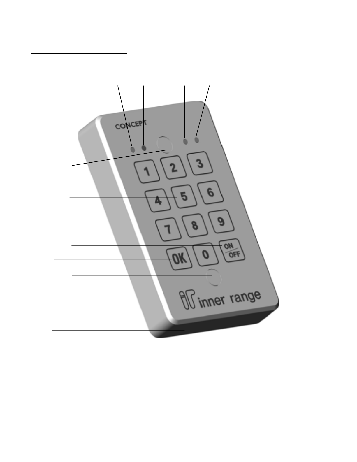
Keypad layout and functions.
Lamp 1 Green CODE (Logged on) On while User is logged on.
Lamp 2 Red ARMED Current Area status. Only displayed while logged on. On = Area On.
Lamp 3 Yellow General purpose. Normally connected to Auxiliary 4.
Lamp 4 Yellow General purpose. Normally connected to Auxiliary 5.
Numeric keys PIN code Entry. When logged on, pressing the 0 key will logoff the User.
OK key. Pressed after PIN code to logon.
Door access request while logged on.
ON/OFF keys. Toggle Area state while logged on.
Buzzer. Buzzer control wire (Yellow) may be connected to Auxiliary 6 to provide Entry/Exit delay warning, etc.
(Rxx:X06 will need to be assigned to the required Area Auxiliary/s)
Lamp 1 Lamp 2 Lamp 3 Lamp 4
Green Red Yellow Yellow
Mounting hole
Numeric keys
ON / OFF key
OK key
Mounting hole
Buzzer
Revision 1.0 March 2006. 3
Installation
Installation environment.
Module PCB: 0º to 40º Celsius and 15% to 85% Relative humidity (non-condensing)
Keypad: -20º to 70º Celsius. Moisture and Dust rating = IP68.
Dimensions.
PCB dimensions: Length: 96mm Width: 96mm
Keypad dimensions: Height: 130mm Width: 81mm Depth: 21mm
Distance between mounting hole centres: 82.2mm
Mounting hole diameter: 4.15mm
Mounting.
1. Choose suitable mounting locations for the keypad and PCB assembly so that:
a) The keypad is at a convenient height for viewing the status lamps and for ease of use.
b) The keypad cable can be terminated into the PCB connectors securely and without strain.
2. a) The PCB assembly can be mounted in a suitable enclosure using the 4 self adhesive PCB standoffs provided, or other suitable
PCB standoffs.
b) One or two “Normally Closed” Tamper switches may be fitted to the enclosure before it is mounted, and wired in parallel
between the “TAMP” and “0V” terminals on T1. (Switch is Open cct when plunger depressed)
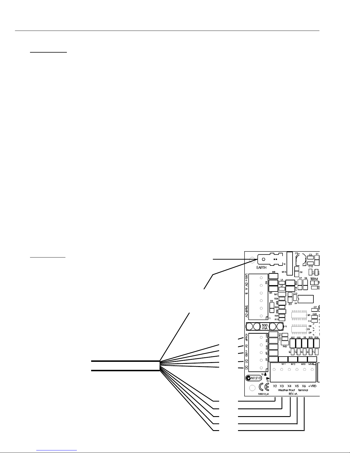
3. Connect the keypad cable to the PCB using the plug-on screw terminal connectors. See diagram below.
4. The Module Number is set using DIPswitches 1 to 7 as required. See table on page 6.
Grey
Black
Red
White
Green
Brown
Blue
V iolet
Orange
Yellow
Keypad cable
Red +12V power supply
Black 0V power supply
Green Data 0’s
White Data 1’s
Brown LED 1 -Green
Blue LED 2 -Red
Violet LED 3 -Yellow
Orange LED 4 -Yellow
Yellow Buzzer
Grey Tamper
Yellow/Green Earth (Connected to case only)
Multicore cable
from keypad
T o building earth
Yellow/Green.
DO NOT
connect to 0V
 Loading...