


Original
Op erating Instructions
and
Service Manual
c
innco systems GmbHR
Erlenweg 12 • D-92521 Schwarzenfeld • Germany
All rights reserved. We accept no liability for the content, especially for damages by existing,
non-existent or erroneous information.
It is not permitted to disclose or complement this document, partial or complete,
unless authorized by innco systems GmbHR.

Original
Op erating Instructions
and
Service Manual
CO3000, RC
c
innco systems GmbHR
Erlenweg 12 • D-92521 Schwarzenfeld • Germany
All rights reserved. We accept no liability for the content, especially for damages by existing,
non-existent or erroneous information.
It is not permitted to disclose or complement this document, partial or complete,
unless authorized by innco systems GmbHR.
innco systems GmbHR
Erlenweg 12
D-92521 Schwarzenfeld
Germany
page 1 phone +49 9435 301 659 0
fax +49 9435 301 659 99
web www.inncosystems.com
mail info@inncosystems.com

Contents
Contents
1 Controller CO3000 3
1.1 Brief Description . . . . . . . . . . . . . . . . . . . . . . . . . . . . . . . . . . . . . . 3
1.2 Technical Data . . . . . . . . . . . . . . . . . . . . . . . . . . . . . . . . . . . . . . . 3
1.3 Control Elements . . . . . . . . . . . . . . . . . . . . . . . . . . . . . . . . . . . . . . 4
1.4 Operational Controls . . . . . . . . . . . . . . . . . . . . . . . . . . . . . . . . . . . . 5
1.5 Power On/O . . . . . . . . . . . . . . . . . . . . . . . . . . . . . . . . . . . . . . . . 7
1.6 Initialization . . . . . . . . . . . . . . . . . . . . . . . . . . . . . . . . . . . . . . . . 8
1.7 Activating Devices . . . . . . . . . . . . . . . . . . . . . . . . . . . . . . . . . . . . . 9
1.8 Referencing Devices . . . . . . . . . . . . . . . . . . . . . . . . . . . . . . . . . . . . 10
1.9 Settings . . . . . . . . . . . . . . . . . . . . . . . . . . . . . . . . . . . . . . . . . . . 11
1.10 Network Settings . . . . . . . . . . . . . . . . . . . . . . . . . . . . . . . . . . . . . . 12
1.11 Device Limits . . . . . . . . . . . . . . . . . . . . . . . . . . . . . . . . . . . . . . . . 13
1.12 Device Speed . . . . . . . . . . . . . . . . . . . . . . . . . . . . . . . . . . . . . . . . 14
1.13 Device Settings . . . . . . . . . . . . . . . . . . . . . . . . . . . . . . . . . . . . . . . 15
1.14 Positioning . . . . . . . . . . . . . . . . . . . . . . . . . . . . . . . . . . . . . . . . . 16
1.15 Store Positions . . . . . . . . . . . . . . . . . . . . . . . . . . . . . . . . . . . . . . . 16
1.16 Recall Positions . . . . . . . . . . . . . . . . . . . . . . . . . . . . . . . . . . . . . . . 17
1.17 Tiltmast Settings . . . . . . . . . . . . . . . . . . . . . . . . . . . . . . . . . . . . . . 18
1.18 Auto-Tilt . . . . . . . . . . . . . . . . . . . . . . . . . . . . . . . . . . . . . . . . . . 19
1.19 Auto-Tilt Settings . . . . . . . . . . . . . . . . . . . . . . . . . . . . . . . . . . . . . 20
1.20 Setup Drawing . . . . . . . . . . . . . . . . . . . . . . . . . . . . . . . . . . . . . . . 21
1.21 Limits Axis . . . . . . . . . . . . . . . . . . . . . . . . . . . . . . . . . . . . . . . . . 22
1.22 Limits Tiltmast . . . . . . . . . . . . . . . . . . . . . . . . . . . . . . . . . . . . . . . 23
1.23 VSWR Settings . . . . . . . . . . . . . . . . . . . . . . . . . . . . . . . . . . . . . . . 24
1.24 Software Update . . . . . . . . . . . . . . . . . . . . . . . . . . . . . . . . . . . . . . 26
2 Slider Setup 29
2.1 Brief Description . . . . . . . . . . . . . . . . . . . . . . . . . . . . . . . . . . . . . . 29
2.2 Antenna Polarization . . . . . . . . . . . . . . . . . . . . . . . . . . . . . . . . . . . . 29
2.3 Toothed Bar Setup . . . . . . . . . . . . . . . . . . . . . . . . . . . . . . . . . . . . . 30
2.4 Correction Modes . . . . . . . . . . . . . . . . . . . . . . . . . . . . . . . . . . . . . . 31
3 Remote Control 32
innco systems GmbHR
Erlenweg 12
D-92521 Schwarzenfeld
Germany
page 2
phone +49 9435 301 659 0
fax +49 9435 301 659 99
web www.inncosystems.com
mail info@inncosystems.com

Controller CO3000
1 Controller CO3000
1.1 Brief Description
The digital controller CO3000 is suited for the operation of antenna masts, turntables, slide bars
and other positioning equipment of innco and innco-systems.
It is operable in manual, semi-automatic and remote control mode.
The "Quick Move" buttons and the "Menu Wheel" enable an intuitive and quick operation.
A 7 display provides clear and precise information for each device.
1.2 Technical Data
Data interface IEEE488 / LAN
Device interface 4-port CAN-Bus via optical ber
Transfer rate 500kBit/s
Display 7 TFT 800x480 pixel
Voltage 100-240V AC (50/60Hz)
Approx. current consumption 20W
Fuse T 1,25A / 250V
Size 3HE 19 Rack mount
(427mm x 134mm x 300mm)
Approx. weight 3kg
Min. temperature 5◦C
Max. temperature 40◦C
innco systems GmbHR
Erlenweg 12
D-92521 Schwarzenfeld
Germany
page 3
phone +49 9435 301 659 0
fax +49 9435 301 659 99
web www.inncosystems.com
mail info@inncosystems.com

Controller CO3000
1.3 Control Elements
Figure 1.1:
Front
Figure 1.2:
Back
1 - Power switch 8 - LAN (TCP/IP) port
2 - Horizontal softkeys 9 - USB port
3 - STOP button 10 - Fiberoptic CAN interface
4 - Vertical softkeys 11 - HCU interface (optional)
5 - Quick move buttons 12 - GPIB (IEEE 488) interface
6 - Data keypad 13 - Main switch / Power socket
7 - Menu wheel
innco systems GmbHR
Erlenweg 12
D-92521 Schwarzenfeld
Germany
page 4
phone +49 9435 301 659 0
fax +49 9435 301 659 99
web www.inncosystems.com
mail info@inncosystems.com

Controller CO3000
1.4 Operational Controls
The buttons are lit when you can use them.
Figure 1.3:
Quick Move Buttons
The
"Quick Move"
buttons let you navigate left/right or up/down. You can also use these buttons
to move the active device.
Other than that, the polarization (horizontal/vertical) can be switched by using the
"H/V"
-button.
Figure 1.4:
Data Keypad
Use the data keypad for direct input of numerical values.
When a menu item is selected, there is no need to push the enter button - just start typing.
Lower keys:
•
"ESC"
exit active menu
•
"CLR"
delete last typed character
•
"Enter"
conrm input value
innco systems GmbHR
Erlenweg 12
D-92521 Schwarzenfeld
Germany
page 5
phone +49 9435 301 659 0
fax +49 9435 301 659 99
web www.inncosystems.com
mail info@inncosystems.com

Controller CO3000
Figure 1.5:
Menu Wheel
The Menu Wheel is used to navigate through the menu by turning it clockwise or counter-clockwise.
Pressing the wheel has the same eect as the
"Enter"
button.
When a Tilt-Mast is connected, it switches between height and elevation input mode on main
display.
Also, the menu wheel is used to move the active device. By turning the wheel, the active device
increases or decreases its current position. The turning speed will aect the movement speed of
the device. This will be indicated by the following graphics:
Figure 1.6:
Speed indicator
Control elements which are able to be used will be displayed directly beneath the menu item.
Figure 1.7:
"Data Keypad"or"Menu Wheel"
| Up/Down | H/V | Left/Right (
"Quick Move"
)
To abort any running process or to stop the movement of a unit, please press the
"Stop"
Button.
Figure 1.8:
Stop Button
ATTENTION: This stopping procedure is NOT an emergency stop!
innco systems GmbHR
Erlenweg 12
D-92521 Schwarzenfeld
Germany
page 6
phone +49 9435 301 659 0
fax +49 9435 301 659 99
web www.inncosystems.com
mail info@inncosystems.com

Controller CO3000
1.5 Power On/O
First, connect the power cable to the power socket.
Then, move the main switch into 'I'-position (ON).
Figure 1.9:
Main Switch / Power Socket
Press the
"Power"
button once, to turn on the controller.
Figure 1.10:
Power Button
Press and hold the
"Power"
button for 3 seconds, to shut o the controller.
innco systems GmbHR
Erlenweg 12
D-92521 Schwarzenfeld
Germany
page 7
phone +49 9435 301 659 0
fax +49 9435 301 659 99
web www.inncosystems.com
mail info@inncosystems.com

Controller CO3000
1.6 Initialization
By pressing the
"Power"
button, the following screen will be shown.
Figure 1.11:
Initialization Screen
During this time all devices which are currently connected to the CAN-bus will be detected and
initialized.
Figure 1.12:
Main Display
All connected devices will be shown in the main display and are ready to be used
(provided they have been referenced) - see chapter 1.8.
innco systems GmbHR
Erlenweg 12
D-92521 Schwarzenfeld
Germany
page 8
phone +49 9435 301 659 0
fax +49 9435 301 659 99
web www.inncosystems.com
mail info@inncosystems.com

Controller CO3000
1.7 Activating Devices
The device in the rst line is automatically activated.
Figure 1.13:
Activating; Main Display
To select an other device, press the vertical softkey next to the device name.
The selected device will be shown in yellow.
innco systems GmbHR
Erlenweg 12
D-92521 Schwarzenfeld
Germany
page 9
phone +49 9435 301 659 0
fax +49 9435 301 659 99
web www.inncosystems.com
mail info@inncosystems.com

Controller CO3000
1.8 Referencing Devices
Before operating, each device must be referenced. Referencing can be done any time.
In case the device has not been referenced,
"NOT REFERENCED"
will be shown in the display.
Figure 1.14:
Referencing; Main Display
Please reference devices in the following cases by pressing the
"Ref."
softkey.
•
A device has been connected to the controller for the rst time
•
The movement of a device has been interrupted (e.g. power loss, emergency stop)
•
An error has occurred at a device (e.g. activated limit switch)
Figure 1.15:
Referencing Device
Press the
"Device"
softkey and then the
"Start Referencing"
softkey
if you need to reference a device once more.
Press the
"Exit"
softkey to leave the setup and return to main display.
innco systems GmbHR
Erlenweg 12
D-92521 Schwarzenfeld
Germany
page 10
phone +49 9435 301 659 0
fax +49 9435 301 659 99
web www.inncosystems.com
mail info@inncosystems.com

Controller CO3000
1.9 Settings
By pressing the
"Settings"
softkey, the following screen will be shown.
Figure 1.16:
Info
The
"Info"
softkey shows the
"Serialnumber"
and the
"Software version"
- they cannot be changed.
"IEEE-Address"
lets you set the desired IEEE-Address number.
"Brightness LCD"
will change the brightness of the display.
"Brightness Keys"
will change the brightness of the keys.
Press the
"Exit"
softkey to leave the setup and return to main display.
innco systems GmbHR
Erlenweg 12
D-92521 Schwarzenfeld
Germany
page 11
phone +49 9435 301 659 0
fax +49 9435 301 659 99
web www.inncosystems.com
mail info@inncosystems.com

Controller CO3000
1.10 Network Settings
By pressing the
"Network"
softkey, the following screen will be shown.
Figure 1.17:
Network
"Mode"
changes from "DHCP" to "Static".
"IP Address"
lets you change the IP address of the controller.
"Netmask"
lets you change the netmask of the controller.
"Gateway"
lets you change the gateway of the controller.
"Port"
lets you change the network port of the controller.
"Hostname"
sets the name of the controller, which is shown in the network.
The
"Reset Page"
softkey resets the values on the active page to default settings.
The
"Reset Devices"
softkey resets the values of every referenced device to default settings.
Press the
"Exit"
softkey to leave the setup and return to main display.
innco systems GmbHR
Erlenweg 12
D-92521 Schwarzenfeld
Germany
page 12
phone +49 9435 301 659 0
fax +49 9435 301 659 99
web www.inncosystems.com
mail info@inncosystems.com
Controller CO3000
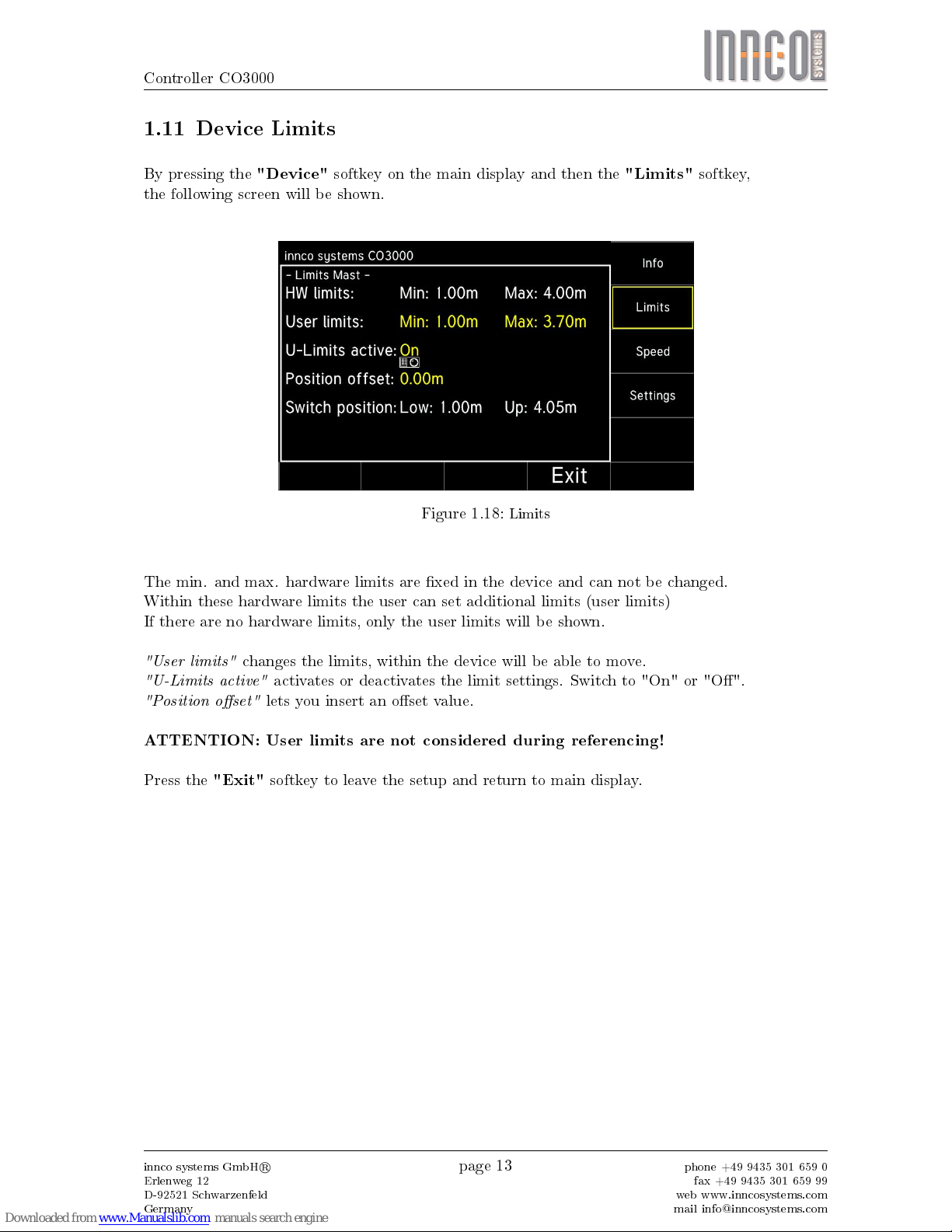
1.11 Device Limits
By pressing the
"Device"
softkey on the main display and then the
"Limits"
softkey,
the following screen will be shown.
Figure 1.18:
Limits
The min. and max. hardware limits are xed in the device and can not be changed.
Within these hardware limits the user can set additional limits (user limits)
If there are no hardware limits, only the user limits will be shown.
"User limits"
changes the limits, within the device will be able to move.
"U-Limits active"
activates or deactivates the limit settings. Switch to "On" or "O".
"Position oset"
lets you insert an oset value.
ATTENTION: User limits are not considered during referencing!
Press the
"Exit"
softkey to leave the setup and return to main display.
innco systems GmbHR
Erlenweg 12
D-92521 Schwarzenfeld
Germany
page 13
phone +49 9435 301 659 0
fax +49 9435 301 659 99
web www.inncosystems.com
mail info@inncosystems.com

Controller CO3000
1.12 Device Speed
By pressing the
"Device"
softkey on the main display and then the
"Speed"
softkey,
the following screen will be shown.
Figure 1.19:
Speed
"Current speed"
lets you set the movement speed.
"Speed unit"
allows you to change the unit of measurement (mm/s, cm/s, m/s, inch/s)
Press the
"Exit"
softkey to leave the setup and return to main display.
innco systems GmbHR
Erlenweg 12
D-92521 Schwarzenfeld
Germany
page 14
phone +49 9435 301 659 0
fax +49 9435 301 659 99
web www.inncosystems.com
mail info@inncosystems.com

Controller CO3000
1.13 Device Settings
By pressing the
"Device"
softkey on the main display and then the
"Settings"
softkey,
the following screen will be shown.
Figure 1.20:
Device Settings
"Name"
lets you rename the device individually.
"Position unit"
allows you to change the unit of measurement (mm, cm, m, inch).
"Mode"
changes from "Step" to "Continuous".
"Stepwidth"
species the step distance wich is run when in "Step" mode.
"Decimal place"
sets the number of decimal places shown on the results.
"Rounding"
lets you round the results. Switch to "On" or "O".
Press the
"Exit"
softkey to leave the setup and return to main display.
innco systems GmbHR
Erlenweg 12
D-92521 Schwarzenfeld
Germany
page 15
phone +49 9435 301 659 0
fax +49 9435 301 659 99
web www.inncosystems.com
mail info@inncosystems.com

Controller CO3000
1.14 Positioning
Use the data keypad or the menu wheel to input a target position.
While the device is moving, a new position can be entered.
The device will stop and move to the new position.
1.15 Store Positions
By pressing the
"Store"
softkey on the main display, the following screen will be shown.
Figure 1.21:
Store Position
To store the position, just enter the position you would like to save, using the data keypad
(up to 4 positioins are storeable)
Please conrm the input values, using the
"Enter"
softkey,
otherwise the position will not be saved.
Saved positions will be shown on the right (Delete S1, Delete S2, ...)
Press the
"Delete ..."
softkey to delete a saved position from the memory.
Press the
"Exit"
softkey to leave the menu and return to main display.
innco systems GmbHR
Erlenweg 12
D-92521 Schwarzenfeld
Germany
page 16
phone +49 9435 301 659 0
fax +49 9435 301 659 99
web www.inncosystems.com
mail info@inncosystems.com

Controller CO3000
1.16 Recall Positions
By pressing the
"Recall"
softkey on the main display, the following screen will be shown.
Figure 1.22:
Recall Stored Position
Press the
"Move to ..."
softkey to recall the saved position from the active device.
The device will immediately move to the restored position.
Press the
"Exit"
softkey to leave the menu and return to main display.
ATTENTION: The recall operation will be canceled if not completed!
innco systems GmbHR
Erlenweg 12
D-92521 Schwarzenfeld
Germany
page 17
phone +49 9435 301 659 0
fax +49 9435 301 659 99
web www.inncosystems.com
mail info@inncosystems.com

Controller CO3000
1.17 Tiltmast Settings
The tiltmast positioner is a combination of minimum two devices:
•
mast with up/down and hor./vert. movement (polarization)
•
+ elevation unit with tilt up/down movement
or (optional)
•
mast + elevation unit (as above)
•
+ slider with forwards/backwards movement
The device is able to automatically correct the antenna elevation.
This occurs in relation to:
•
object height
•
antenna height
•
antenna length
•
measurement distance
When a mast with "Auto-Tilt" function is connected, the following screen will be shown.
Figure 1.23:
Main Display
Notes below the device name indicate, whether the respective function is activated.
e.g.
"AUTO-TILT"
or/and
"ANT-PROT"
will be shown when active.
First, the actual height is shown.
Above, you can see wether
"ANT-REF-H."or"MAST-HEIGHT"
is activated.
Second, the actual polarization is shown. (hor./vert.)
Third, the actual degree of elevation is shown.
By pressing the
"H/V"
button, the polarization axis will be switched.
Pressing the Menu Wheel lets you switch between height and elevation.
innco systems GmbHR
Erlenweg 12
D-92521 Schwarzenfeld
Germany
page 18
phone +49 9435 301 659 0
fax +49 9435 301 659 99
web www.inncosystems.com
mail info@inncosystems.com

Controller CO3000
1.18 Auto-Tilt
There are two types of measurement.
Mast Height and Antenna Reference Height
When the system is set to "MAST HEIGHT", the inserted height value will relate to
the mast basket reference mark.
When set to "ANT-REF-HEIGHT", the inserted height value will relate to
the antenna reference mark.
Please consider this while setting up and conguring the Tilt-Mast.
innco systems GmbHR
Erlenweg 12
D-92521 Schwarzenfeld
Germany
page 19
phone +49 9435 301 659 0
fax +49 9435 301 659 99
web www.inncosystems.com
mail info@inncosystems.com

Controller CO3000
1.19 Auto-Tilt Settings
By pressing the
"Device"
softkey in the main menu and then the
"Auto-Tilt"
softkey,
the following screen will be shown.
Figure 1.24:
Auto-Tilt O
To enable the
"Auto-Tilt"
function, it needs to be switched to "On" rst.
Figure 1.25:
Auto-Tilt On
"Auto-Tilt"
lets you activate/deactivate the elevation correction. Switch to "On" or "O".
"HEIGHT-AXIS MODE"
indicates which measurement type is being used.
"Object-Setup"
lets you choose the height of the object to be measured.
"Mast-Setup"
set
"ANT-REF-LENGTH"
and
"SETUP M-DISTANCE"
as shown on next page.
> it is preferred to set the "SETUP M-DISTANCE" directly after referencing a device.
"Auto-Distance"
will show if a "Slider" has been connected or not.
innco systems GmbHR
Erlenweg 12
D-92521 Schwarzenfeld
Germany
page 20
phone +49 9435 301 659 0
fax +49 9435 301 659 99
web www.inncosystems.com
mail info@inncosystems.com

Controller CO3000
1.20 Setup Drawing
Figure 1.26:
Setup Drawing
If there isnoslider connected, the
'SETUP M-DISTANCE'
is the same as Measurement Distance.
The mast will have to be moved manually into position or the antenna
will have to be moved to the correct position, using the polarisation-tube.
ATTENTION:
Moving the antenna will change the Ant.-Ref.-Length! If necessary, adjust!
For operation
with
slider, please use the Slider Setup manual.
innco systems GmbHR
Erlenweg 12
D-92521 Schwarzenfeld
Germany
page 21
phone +49 9435 301 659 0
fax +49 9435 301 659 99
web www.inncosystems.com
mail info@inncosystems.com

Controller CO3000
1.21 Limits Axis
The display shows the active axis on the top in green.
Figure 1.27:
Limits Tiltmast
Change the active axis by pressing the
"Change Axis"
softkey or the
"H/V"
button.
"User limits"
changes the limits, within the device will be able to move.
"U-Limits active"
activates or deactivates the limit settings. Switch to "On" or "O".
"Position oset"
lets you insert an oset value.
"Tilt Ant. Protection"
lets you set the minimum height, when at maximum tilt angle,
to protect the mounted antenna. Switch to "On" or "O".
Press the
"Exit"
softkey to leave the menu and return to main display.
innco systems GmbHR
Erlenweg 12
D-92521 Schwarzenfeld
Germany
page 22
phone +49 9435 301 659 0
fax +49 9435 301 659 99
web www.inncosystems.com
mail info@inncosystems.com

Controller CO3000
1.22 Limits Tiltmast
By pressing the
"Limits"
softkey, the following screen will be shown.
Figure 1.28:
Limits Tiltmast
The min. and max. hardware limits are xed in the device and can not be changed.
Within these hardware limits the user can set additional limits (user limits)
If there are no hardware limits, only the user limits will be shown.
ATTENTION:
User Limits are always referenced to the Mast Height - not to the Ant-Ref-Height!
"User limits"
changes the limits, within the device will be able to move.
"U-Limits active"
activates or deactivates the limit settings. Switch to "On" or "O".
"Position oset"
lets you insert an oset value.
"Tilt Ant. Protection"
lets you set the max. tilt-angle, when at 1m height,
to protect the mounted antenna. Switch to "On" or "O".
innco systems GmbHR
Erlenweg 12
D-92521 Schwarzenfeld
Germany
page 23
phone +49 9435 301 659 0
fax +49 9435 301 659 99
web www.inncosystems.com
mail info@inncosystems.com

Controller CO3000
1.23 VSWR Settings
The VSWR positioner is a combination of two devices:
•
The slide with left and right movement
•
The turn unit with corrective rotation left and right (automatic correction is optional)
Figure 1.29:
The device is able to correct the antenna direction according to the antenna distance to DUT and
the slider center position.
The mentioned parameters can be adjusted in the "Extras" of the device settings.
innco systems GmbHR
Erlenweg 12
D-92521 Schwarzenfeld
Germany
page 24
phone +49 9435 301 659 0
fax +49 9435 301 659 99
web www.inncosystems.com
mail info@inncosystems.com

Controller CO3000
By pressing the
"Device"
softkey in the main menu and then the
"Extras"
softkey,
the following screen will be shown.
Figure 1.30:
VSWR Position
"Auto-Azimuth"
enables the direction correction. Switch to "On" or "O".
"Centre position"
set the centre position of the slider. (Reference for the 0◦position)
"Distance to DUT"
will aect the correction angle according to the following drawing.
Distance to DUT
Centre Position
1
1
2
2
3
3
4
4
5
5
6
6
7
7
8
8
A A
B B
C C
D D
E E
F F
Figure 1.31:
VSWR Setup
innco systems GmbHR
Erlenweg 12
D-92521 Schwarzenfeld
Germany
page 25
phone +49 9435 301 659 0
fax +49 9435 301 659 99
web www.inncosystems.com
mail info@inncosystems.com

Controller CO3000
1.24 Software Update
If new software is available, it can be downloaded from our homepage or will be provided by our
service team.
For the update it is necessary to connect the CO3000 to a computer.
ATTENTION: Do not use a USB hub!
Connect the CO3000 USB port on the rear panel with a USB cable (Type A to Type B)
directly to a free USB port on the PC.
Windows will now load the USB driver for the CO3000.
No user interaction will be required.
If the CO3000 is connected to the PC for the rst time, a short message on the task bar
will appear, that the device is now ready to use.
Now the controller can be updated by starting the program "Updater.exe".
Figure 1.32:
Update Start
The update program shows:
"Connected"
and
"Controller Reboot required"
.
Please reboot the controller now. (Power o, then power on).
innco systems GmbHR
Erlenweg 12
D-92521 Schwarzenfeld
Germany
page 26
phone +49 9435 301 659 0
fax +49 9435 301 659 99
web www.inncosystems.com
mail info@inncosystems.com

Controller CO3000
During reboot, the following screen will be shown on the controller.
Figure 1.33:
Update Mode Controller
After rebooting, the message
"Controller Reboot required"
will change to
"Ready to Update"
.
Figure 1.34:
Update Process
Please click
"Open File"
and choose the provided update le (*.CO3000 le type)
Now click
"Start Update"
to start update process.
The update process can take up to 10 minutes.
ATTENTION: Do not switch o or disconnect the controller during this time!
innco systems GmbHR
Erlenweg 12
D-92521 Schwarzenfeld
Germany
page 27
phone +49 9435 301 659 0
fax +49 9435 301 659 99
web www.inncosystems.com
mail info@inncosystems.com

Controller CO3000
After a successful update, the following screen will be shown.
Figure 1.35:
Update Done
The update software can now be closed and the USB cable disconnected.
The controller will reboot automatically and is ready to use.
innco systems GmbHR
Erlenweg 12
D-92521 Schwarzenfeld
Germany
page 28
phone +49 9435 301 659 0
fax +49 9435 301 659 99
web www.inncosystems.com
mail info@inncosystems.com

Slider Setup
2 Slider Setup
2.1 Brief Description
The slider is an additional unit to the antenna mast with auto-tilt function.
A toothed bar, mounted to the oor and a drive unit, mounted to the mast are the main components.
How to set up the toothed bar and the antenna mast is described in this manual.
2.2 Antenna Polarization
Please follow the steps as shown below. If necessary, take the controller manual at hand.
Figure 2.1:
Polarization Tube
•
Bring the mast basket into the maximum tilt position
•
Make sure, the antenna is in vertical position
•
Mount the adaptor and the antenna to the polarization tube
•
Adjust the polarization tube, to ensure the antenna does not collide with the mast
> If this is not possible, adjust the maximum tilt-angle in the controller's "User Limits" settings.
•
Make sure, the polarization tube is tightened rmly
innco systems GmbHR
Erlenweg 12
D-92521 Schwarzenfeld
Germany
page 29
phone +49 9435 301 659 0
fax +49 9435 301 659 99
web www.inncosystems.com
mail info@inncosystems.com

Slider Setup
2.3 Toothed Bar Setup
Figure 2.2:
Setup
•
Bring the antenna into 0◦position (horizontal)
•
Add the Ant.-Ref.-Length, the Measurement Distance and a little reserve (approx. 2-3cm)
This will be your
"Slider-Setup-Distance"
•
Mark the oor at the calculated Distance from the DUT
•
Place the toothed bar on the oor, so the mark on the oor matches the mark on the bar
•
Make sure, the direction of the bar's mark is pointing towards the DUT
•
Fix the bar to the oor (screw or tape)
•
Place the mast(-drive) on top of the toothed bar
•
Reference the mast as described in the CO3000 manual
•
After referencing, measure the"SETUP M-DIST" and insert it in the controller
innco systems GmbHR
Erlenweg 12
D-92521 Schwarzenfeld
Germany
page 30
phone +49 9435 301 659 0
fax +49 9435 301 659 99
web www.inncosystems.com
mail info@inncosystems.com

Slider Setup
2.4 Correction Modes
Distance Correction Height Correction
To correct dierences in distance, the slider will move forward or backward.
To correct dierences in height, the antenna will tilt up or down.
ATTENTION: It ist not possible to tilt in a negative direction!
innco systems GmbHR
Erlenweg 12
D-92521 Schwarzenfeld
Germany
page 31
phone +49 9435 301 659 0
fax +49 9435 301 659 99
web www.inncosystems.com
mail info@inncosystems.com

Remote Control CO3000
for Innco Systems devices
Document version: v2.10
Date: 2016-06-28
Written by: Thomas Witzenbichler (TW)
Tony Schinkowski (TS)
Valid from CO3000 SW Version: v1.02.60
Document-History
Version Date Author Changes CO3000 Version
v1.0 2012-08-22 TW Initial version v1.01.02
v1.1 2013-01-31 TW Changes GPIB index DS & CT v1.01.10
v1.2 2013-04-16 TW Gantry device added, Correction axis
documentation of XYZ-Positioner
v1.02.01
v1.3 2013-10-04 TW Compound device added. Mast-Rotator added v1.02.08
v1.4 2014-05-20 TW New speed command NSP added v1.02.11
v1.5 2014-07-28 TW Tiltmast (TMP) added
Tiltmast-Slider (TMS) added
v1.02.12
v1.6 2015-05-06 TS VSWR-Compound added v1.02.25
v1.7 2015-05-18 TS Updated Tiltmast (TMP) v1.02.26
v1.8 2015-06-30 TS Added FSM Compound v1.02.33
v1.9 2015-10-05 TS Added STATUS command, see
3.1 General Commands
v1.02.37
v1.10 2015-11-30 TS New Commands for
- Tiltmast (TMP) Antenna-Protection
- Tiltmast (TMP) Auto-Tilt
- Tiltmast (TMP+TMS) Auto-Distance
- VSWR-Compout Auto-Azimuth
- Gantry Antenna-Compensation
v1.02.38
v2.00 2016-06-07 TS Tiltmast (TMP): Reworked Auto-Tilt v1.02.50
v2.10 2016-06-28 TS Tiltmast (TMP): Reworked Auto-Distance v1.02.60
innco systems GmbH
Erlenweg 12
92521 Schwarzenfeld
phone: +49 (0)9435 301659 0
fax: +49 (0)9435 301659 99
e-mail: info@inncosystems.com
© innco systems GmbH Schwarzenfeld/Germany
Erlenweg 12, 92521 Schwarzenfeld/Germany Phone: +49 9435 301659 0 Fax: +49 9435 301659 99
Email: info@inncosystems.com
3

web: www.inncosystems.com
© innco systems GmbH Schwarzenfeld/Germany
Erlenweg 12, 92521 Schwarzenfeld/Germany Phone: +49 9435 301659 0 Fax: +49 9435 301659 99
Email: info@inncosystems.com

Table of Content
1 General............................................................................................................................................... 3
1.1 Terminology.................................................................................................................................................... 3
1.2 Other Terminology.......................................................................................................................................... 3
2 Remote System.................................................................................................................................. 4
2.1 Basic Information............................................................................................................................................ 4
2.2 Connecting via GPIB....................................................................................................................................... 4
2.3 Connection via Network (LAN / Ethernet)....................................................................................................... 5
2.4 Addressing Devices........................................................................................................................................6
2.5 Error messages............................................................................................................................................... 6
3 Remote Commands............................................................................................................................ 7
3.1 General Commands........................................................................................................................................ 7
3.2 Mast (MA), Minimast (MM).............................................................................................................................. 9
3.3 Twinmast (TW: TWX, TWZ), Tiltmast (TM: TMX, TMZ)................................................................................11
3.4 Rotary table (DT), Rotary unit (DE), Rotary disc (DS), Compact table (CT), Mast rotator (MR)..................13
3.5 XYZ-Positioner (XYZ: X, Y, Z)...................................................................................................................... 15
3.6 Field probe mast (FSM: FX, FY)................................................................................................................... 17
3.7 Slidebar (KMS).............................................................................................................................................. 19
3.8 Mast Positioner (MP).................................................................................................................................... 21
3.9 VSWR Compound (VSWR: VS, VSA).......................................................................................................... 23
3.10 VSWR Positioner (VSWR).......................................................................................................................... 26
3.11 Antenna stand (AS)..................................................................................................................................... 28
3.12 Gantry with Polarisation (GAP)................................................................................................................... 29
3.13 Gantry without Polarisation (GA)................................................................................................................ 31
3.14 Compound Device Mast (CD: CDH, CDP, CDE)........................................................................................33
3.15 Tiltmast (TMP: TMPM, TMPE).................................................................................................................... 35
3.16 Tiltmast Slider (TMS), Tiltmast-Positioner Extension.................................................................................38
4 Examples.......................................................................................................................................... 40
4.1 Opt Command............................................................................................................................................... 40
4.2 Addressing.................................................................................................................................................... 40
4.3 Reading current position............................................................................................................................... 40
4.4 Moving axes.................................................................................................................................................. 41
4.5 Error messages............................................................................................................................................. 41
4.6 Setting a Register......................................................................................................................................... 42
4.7 Polarisation................................................................................................................................................... 42
© innco systems GmbH Schwarzenfeld/Germany
Erlenweg 12, 92521 Schwarzenfeld/Germany Phone: +49 9435 301659 0 Fax: +49 9435 301659 99
Email: info@inncosystems.com

1 General
1.1 Terminology
IEEE488: External Parallel Data Bus
GPIB: General Purpose Interface Bus, or General Purpose Instrumentation Bus
EOI: End Or Identify
Listener GPIB condition of the device’s ability to receive messages
Talker GPIB condition of the device’s ability to receive messages
LF: Line Feed
LAN: Local Area Network, Network Connection
TCP/IP: Transmission Control Protocol / Internet Protocol, used by the LAN
Subnet Contiguous partial network within a LAN network
Hostname Unique name of a computer in the network
DHCP Dynamic Host Configuration Protocol, automatic IP address assignment
HTTP Hyper Text Transfer Protocol, Protocol for Websites
Socket Connection for exchanging data in networks and procedures
Network mask Bitmask for setting up subnets in a network
Gateway Protocol implementer for communicating via Internet
1.2 Other Terminology
nnn Floating point number, up to one decimal place, negative and positive
◦ e.g.: 0, 1, 0.0, 0.1, -100.5, 42.3
ppp Floating point number, up to one decimal place, only positive
◦ e.g.: 0, 1, 0.0, 0.1, 100.5, 42.3
iii Integernumber
◦ e.g.: 0, 1, 123, -456
© innco systems GmbH Schwarzenfeld/Germany
Erlenweg 12, 92521 Schwarzenfeld/Germany Phone: +49 9435 301659 0 Fax: +49 9435 301659 99
Email: info@inncosystems.com

2 Remote System
2.1 Basic Information
Using a GPIB or LAN connection, the CO3000 can be triggered and used to control devices
connected to it. The commands used for this are coded in simple, readable character strings. The
following applies to all connections:
Character set: ASCII 8Bit
All incoming and outgoing communications are completed with LineFeed “LF” (0x0A)
◦ for IEEE488, LF and/or EOI can be used
Maximum length of incoming character string: 64 bytes, including LF
Maximum length of outgoing character string: 64 bytes, including LF
All characters must be transmitted in capital letters. The separator is a space (0x20)
All commands sent to the CO3000 are confirmed with a return value for each
◦ Each command can however also be answered with an error message.
2.2 Connecting via GPIB
2.2.1 Connection
To connect remotely via GPIB, the PC must have a GPIB interface. There are several suppliers for
suitable add-on cards or USB adaptors, e.g. National and Agilent. You will need an IEEE-488 cable to
connect it with.
The CO3000 is delivered with the default GPIB address 7. This can be changed in the controller’s
settings.
2.2.2 Communication
Communication runs on the GPIB standard. To receive commands, the CO3000 must be addressed
as a listener and to send the return value it must be addressed as a talker. Return values can be read
several times.
Return values are available for reading immediately after being received and decoded.
© innco systems GmbH Schwarzenfeld/Germany
Erlenweg 12, 92521 Schwarzenfeld/Germany Phone: +49 9435 301659 0 Fax: +49 9435 301659 99
Email: info@inncosystems.com

2.3 Connection via Network (LAN / Ethernet)
The CO3000 can be operated in a normal TCP/IP network. It has no website. It is not possible to run it
via an internet browser!
2.3.1 Connection
The controller can be connected to a PC or switch by using a normal network cable (not crossover!) in
the network socket in the back of the CO3000.
2.3.2 Settings
DHCP mode (Preset) Static mode (Example)
Hostname CO3000 CO3000
IP address Automatic 192.168.0.42
Network mask Automatic 255.255.255.0
Gateway Automatic 192.168.0.1
Port 5025 5025
The CO3000 is delivered with the DHCP activated. If a static address is desired, this can be set on the
CO3000.
In its original setting, the hostname “CO3000” is preset. If you are operating several controllers on the
same subnet, the hostnames must be unique. Depending on the DHCP server you are using on the
network, various negative effects can occur on the network if several network-capable devices use the
same hostname. The hostname can be changed in the CO3000 settings.
The settings for the gateway are irrelevant in most cases, because the CO3000 does not make an
Internet connection.
2.3.3 Communication
No additional protocols such as HTTP are used. Sockets can be used for communication. The
commands can be written directly to the previously opened socket and the return values read from it.
When communicating via LAN, please note that unlike GPIB it is not possible to read a return value
from the CO3000 several times. A return value can only be read if a command has been sent to the
CO3000.
After receiving and decoding the command, the CO3000 will immediately send the return value to the
invoker. Depending on the network, it may take some time to receive the return value (> 100ms).
© innco systems GmbH Schwarzenfeld/Germany
Erlenweg 12, 92521 Schwarzenfeld/Germany Phone: +49 9435 301659 0 Fax: +49 9435 301659 99
Email: info@inncosystems.com

2.4 Addressing Devices
Each axis of a device is assigned an address between 0 and 15. If an address is already occupied by
a device, newly added devices will be assigned a higher address.
An exception to this address assignment is the polarisation axis of the mast devices. The polarisation
is described by itself in the sections under each device.
Example of numerical addressing:
Mast selection : LD 0 DV
Selecting a rotary table DT2: LD 5 DV
Selecting an X-axis of an XYZ positioner: LD 4 DV
In addition to numerical addressing, a device can also be triggered via a named address. This has the
advantage that a device can have a unique name in the remote system and be triggered by this name
even if a newly added device could change the numerical address.
Device names can be given out using the *OPT? Command. See 3.1. General Commands und
4.1.Opt Command
Named Addresses:
Mast selection: LD MA1 DV
Selecting a rotary table DT2: LD DT2 DV
Selecting an X-axis of an XYZ positioner: LD X1 DV
2.5 Error messages
All entries are confirmed with a return value. In case of an error, one of the four error codes is
returned.
“E - P” Power: Is sent after a loss of the power supply.
“E - S” Syntax: Is sent when there was an error in the command.
“E - V” Value: Is sent when a value is not within the limits.
“E - D” Device: Is sent hen a device fails to react for a long time. This means that the
motor is not moving. Is also sent when the addressed device does not
exist.
© innco systems GmbH Schwarzenfeld/Germany
Erlenweg 12, 92521 Schwarzenfeld/Germany Phone: +49 9435 301659 0 Fax: +49 9435 301659 99
Email: info@inncosystems.com

3 Remote Commands
Important: Each command sent to the controller is confirmed with a return value. The return values
listed in the tables below are the values returned in case of success. In case of error, the error codes
listed under 2.4. Error Messages may be given at any command.
3.1 General Commands
General Commands
Command Return Description
ES 1 Emergency Stop
Stops all movements of all connected devices
LO 1 Log Out, leave remote-modus. Any currently executed device
movement will be completed.
*IDN? inncoCO3000/a
aa/bbb
Returns the identification string
aaa: Serial number, variable character string length
bbb: CO3000 Version number, variable character string length
*OPT? Depends on
device.
Without devices:
0,0,0,0,0,0,0,0,
0,0,0,0,0,0,0,0
Returns the named addresses of the connected devices. The
numerical address is derived from the index of named
addresses.
Example with Mast, Rotary Table and XYZ Positioner :
“MA1,DT1,0,0,X1,0,0,0,Y1,0,0,0,Z1,0,0,0”
- Mast MA1 has the address 0 (Index 0)
- Rotary Table DT1 has the address 1 (Index 1)
- Addresses of XYZ_Axes: 4, 8 and 12 (Index 4,8,12)
LD xxxn DV xxxn
(see above)
Load one axis of one device and enter remote-modus,
Addressing by name
Examples (compare with example of *OPT? above)
LD MA1 DV
LD DT1 DV
LD X1 DV
LD Y1 DV
LD Z1 DV
LD d DV d Lode one axis of one device and enter remote-modus,
Addressing by index
Index d starts at 0 (see *OPT? above)
Examples (compare with example of *OPT? above)
LD 0 DV
LD 1 DV
LD 4 DV
LD 8 DV
LD 12 DV
STATUS d ?
STATUS n ?
x, b, nnn EE
- or -
x, b, ppp EE
- or -
x, b, nnn EE, pp
- or -
x, b, nnn EE, pp
Query the status of the device and axis.
Can use numerical addressing (d) or name addressing (n).
d: Numerical address of the device
x: Name of the device
b: Busy status of the device (0=stopped 1=moving)
nnn, ppp: The current position of the device
EE: Unit, can be CM (Centimetre) or DG (Degree)
pp: Polarisation PV, PH, or P- (moving)
Example:
STATUS MA1 ?
© innco systems GmbH Schwarzenfeld/Germany
Erlenweg 12, 92521 Schwarzenfeld/Germany Phone: +49 9435 301659 0 Fax: +49 9435 301659 99
Email: info@inncosystems.com

General commands (work on selected device and axis)
Command Return Description
ST 1 Stops currently selected axis movement
Does not leave remote-modus
LD nnn EE RR
LD ppp EE RR
LD iii EE RR
Depends on
EE and RR
Load command, loads a value to a register
LD: Load
nnn, ppp, iii assigned register values
EE: Unit, valid character string:
- CM (Centimetre)
- DG (Degree)
- INT (Integer)
RR: Register, valid registers are described in each device
Example:
LD 350 CM UL
LD 123 CM NP
LD s SP s Sets the speed of the currently selected axis.
Valid values for s: 1-8,
1: minimum speed
8: maximum speed
Example:
LD 4 SP
LD ppp NSP ppp Sets the speed of the currently selected axis.
In cm/s or degree/s
LD nnn CM NP
LD ppp CM NP
LD nnn DG NP
LD ppp DG NP
1 New Position, Register is loaded using LD - see devices
Example:
LD 123 CM NP
GO 1
Moves the axis to the value in register NP
LD nnn CM NP GO
LD ppp CM NP GO
LD nnn DG NP GO
LD ppp DG NP GO
Load New Position and move the axis to this position
Example:
LD 123 CM NP GO
BU 0 or 1
BU = 1: Motor on; BU = 0: Motor off
This register shows if one of the motors is currently moving.
For mechanical reasons, the motor cannot implement the
movement immediately after the start command. It is therefore
necessary to wait until the mast starts moving before you can
use BU to check if the last command is complete. Even if the
mast has already reached its target BU will still remain at the
value 1 for approx. 0.5 seconds.
HO 1 Starts referencing for the selected device.
All axis of the device are referenced.
© innco systems GmbH Schwarzenfeld/Germany
Erlenweg 12, 92521 Schwarzenfeld/Germany Phone: +49 9435 301659 0 Fax: +49 9435 301659 99
Email: info@inncosystems.com

3.2 Mast (MA), Minimast (MM)
3.2.1 General
Supported devices
◦ Mast (MA): 0x21..
◦ Minimast (MM): 0x23..
All values are transmitted in CM (cm).
Negative values are not possible.
3.2.2 Register
Addressing
Command Return value Description
LD d DV d Load X-axis mast, numerical addressing
Valid values for d: 0, 4, 8, 12
LD MAd DV
LD MMd DV
Index of
MAd/MMd from
*OPT? return
Load X-axis mast, named addressing
Valid values for d: 1, 2, 3, ..
Read commands
Command Return value Description
CP ppp ppp: Current Position in cm
BU 0 or 1
Motor Operation Status
0: Motor is off
1: Motor is on
MP ppp
ppp: Mast position in cm
Changes the address to the X-axis of the mast. All
following commands will relate to the X-axis of the
mast.
P? 0 or 1 Polarisation, 0: horizontal, 1: vertical
UL ppp
ppp: Upper Limit X-axis in cm
LL ppp
ppp: Lower Limit X-axis in cm
SP 1 to 8
Current Speed X-axis
NSP ppp
Current speed X-axis in cm/s
© innco systems GmbH Schwarzenfeld/Germany
Erlenweg 12, 92521 Schwarzenfeld/Germany Phone: +49 9435 301659 0 Fax: +49 9435 301659 99
Email: info@inncosystems.com

Write Commands
Command Return Value Description
LD ppp CM UL ppp Sets upper limit to ppp cm
This must not be greater than the hardware limits and
should not be less than the hardware’s lower device
limit.
LD ppp CM LL ppp Sets lower limit to ppp cm
This must not be less than the hardware limits and
should not be greater than the hardware’s upper
device limit.
LD s SP s Sets new speed for X-axis
Valid values for s: 1-8
LD ppp NSP ppp Sets new speed for X-axis in cm/s
Control Commands
Command Return Value Description
ST 1 Stops all movements in all connected devices
UP 1
Moves the mast basket upwards until the upper limit
is reached or the command STOP(ST) is sent.
DN 1
Moves the mast basket downwards until the lower
limit is reached or the command STOP(ST) is sent.
PV 1 Polarise vertical
PH 1 Polarise horizontal
LD ppp CM NP 1 Load ppp cm in Register NP (New Position)
GO 1 Move the mast basket according to NP
© innco systems GmbH Schwarzenfeld/Germany
Erlenweg 12, 92521 Schwarzenfeld/Germany Phone: +49 9435 301659 0 Fax: +49 9435 301659 99
Email: info@inncosystems.com

3.3 Twinmast (TW: TWX, TWZ), Tiltmast (TM: TMX, TMZ)
3.3.1 General
Supported devices
◦ Twinmast (TW): 0x2A.
◦ Tiltmast (TM): 0x28.., 0x29..
All values are transmitted in CM (cm) or DG (degrees).
Negative values are not possible.
3.3.2 Register
Addressing
Command Return value Description
LD x DV x Load X-axis Twinmast/Tiltmast, numerical addressing
Valid values for x: 0, 3, 6, 9, 12, 15
LD z DV z Load Z-axis Twin/Tilt-Mast, numerical addressing
Valid values for y: 3, 6, 9, 12, 15
LD TWXd DV
LD TWZd DV
LD TMXd DV
LD TMZd DV
Index of TWXd,
TWZd,.. from
*OPT? return
Load X-axis Twinmast (TW)
Load Z-axis Twinmast (TW)
Load X-axis Tiltmast (TM)
Load Z-axis Tiltmast (TM)
Valid values for d: 1, 2, 3, ....
Read Commands
Command Return Value Description
CP ppp ppp: Current position of the X-Axis in cm
TA ppp ppp: Current position of Z-Axis (Swing) in degree
BU 0 or 1
Motor Operational Status
0: Motor is off
1: Motor is on
MP ppp
ppp: Mast position of X-Axis in cm
Changes the address to the X-Axis of the Mast. All
following commands will relate to the X-Axis of the
Mast.
P? 0 or 1 Polarisation, 0: horizontal, 1: vertical
UL ppp
ppp: Upper Limit X-Axis in cm
LL ppp
ppp: Lower Limit X-Axis in cm
TL ppp
ppp: Swing Limit of Z-Axis in degrees
Maximum deviation from the horizontal position in
degrees downwards and upwards.
SP 1 to 8
Speed of the current axis
NSP ppp
Speed of the current axis. X-axis in cm/s, Z-axis in
Degree/s
© innco systems GmbH Schwarzenfeld/Germany
Erlenweg 12, 92521 Schwarzenfeld/Germany Phone: +49 9435 301659 0 Fax: +49 9435 301659 99
Email: info@inncosystems.com

Write Commands
Command Return Value Description
LD ppp CM UL ppp Sets upper limit of X-Axis to ppp cm
ppp must not be greater than the hardware limits and
should not be less than the hardware’s lower device
limit.
LD ppp CM LL ppp Sets lower limit of X-Axis to ppp cm
ppp must not be less than the hardware limits and
should not be greater than the hardware’s upper
device limit.
LD ppp DG TL ppp
Sets swing limit of the Z-Axis to ppp degrees
Swing Limit: Maximum deviation of the horizontal
position in degrees upwards and downwards.
ppp must not exceed the hardware limits of the Z-
Axis.
LD s SP s Sets new speed for the currently selected axis: X or Z
Valid values for s: 1-8
LD ppp NSP ppp Sets new speed for the currently selected axis. X-axis
in cm/s, Z-Axis in degree/s
Control Commands
Command Return Value Description
ST 1 Stops all movements in all connected devices
UP 1
Moves the mast basket (X-Axis) upwards until the
upper limit is reached
DN 1
Moves the mast basket (X-Axis) downwards until the
lower limit is reached
PV 1 Polarise vertical
PH 1 Polarise horizontal
TF 1 Swings downwards until the swing arm’s lower limit is
reached
TU 1 Swings upwards until the swing arm’s upper limit is
reached
LD ppp CM NP 1 Load ppp cm in Register NP (New Position),
X-Axis must be previously selected!
LD ppp DG NP 1 Load ppp Grad in Register NP (New Position)
Z-Axis must be previously selected!
GO 1 Moves the selected axis to NP
© innco systems GmbH Schwarzenfeld/Germany
Erlenweg 12, 92521 Schwarzenfeld/Germany Phone: +49 9435 301659 0 Fax: +49 9435 301659 99
Email: info@inncosystems.com

3.4 Rotary table (DT), Rotary unit (DE), Rotary disc (DS),
Compact table (CT), Mast rotator (MR)
3.4.1 General
Supported devices
◦ Rotary table (DT): 0x1A.., 0x1B..0x19.., 0x18..
◦ Rotary unit (DE): 0x01.., 0x48..
◦ Rotary disc (DS): 0x04..
◦ Compact table (CT): 0x0400
◦ Mast rotator (MR) 0x0450
All values are transmitted in DG (degrees).
3.4.2 Register
Addressing
Command Return Value Description
LD d DV d Load Table, numerical addressing
- Rotary table d: 1, 5, 9, 13
- Rotary unit d: 3, 7, 11, 14
- Rotary disc d: 1, 5, 9, 13
- Compact table d: 1, 5, 9, 13
- Mast rotator d: 1, 5, 9, 13
LD DTd DV
LD DEd DV
LD DSd DV
LD CTd DV
LD MRd DV
Index of DTd,
DEd,.. from
*OPT? return
Load Table, named addressing
Valid values for d: 1, 2, 3, ...
Read Commands
Command Return Value Description
CP nnn nnn: Current Position in Grad
BU 0 or 1
Motor Operational Status, Return:
0: Motor is off
1: Motor is on
TP nnn
nnn: Table position in degrees
Changes the address to the table. All following
commands will relate to the table.
WL
nnn nnn: Limit in clockwise degrees
CL
nnn nnn: Limit in anticlockwise degrees
SP 1 to 8
Current speed
NSP ppp
Current speed in Degree/s
© innco systems GmbH Schwarzenfeld/Germany
Erlenweg 12, 92521 Schwarzenfeld/Germany Phone: +49 9435 301659 0 Fax: +49 9435 301659 99
Email: info@inncosystems.com

Write Commands
Command Return Value Description
LD nnn DG WL nnn
Sets clockwise limit to nnn degrees
This must not be greater than the hardware limits and
should not be less than the hardware’s lower device
limit.
LD nnn DG CL
nnn Sets anticlockwise limit to nnn degrees
This must not be less than the hardware limits and
should not be greater than the hardware’s upper
device limit.
LD s SP s Sets new speed for the device
Valid values for s: 1-8
LD ppp NSP ppp Sets new speed for the device in degree/s
Control Commands
Command Return Value Description
ST 1 Stops all movements in all connected devices
CW 1 Moves the table clockwise until the limit is reached
CC 1 Moves the table anticlockwise until the limit is
reached
LD nnn DG NP 1 Load nnn degrees in Register NP (New Position)
GO 1 Move the table to NP
© innco systems GmbH Schwarzenfeld/Germany
Erlenweg 12, 92521 Schwarzenfeld/Germany Phone: +49 9435 301659 0 Fax: +49 9435 301659 99
Email: info@inncosystems.com

3.5 XYZ-Positioner (XYZ: X, Y, Z)
3.5.1 General
Supported devices
◦ XYZ-Positioner (XYZ): 0xA0..
All values are transmitted in CM (cm)
Negative values are not possible
Each axis of the positioner is controlled individually. Only one axis can be moved at a time. As
long as BU=1, no new command will be carried out.
3.5.2 Register
Addressing
Command Return Value Description
LD x DV x Load X-Axis, numerical addressing
Valid values for x: 4
LD y DV x Load Y-Axis, numerical addressing
Valid values for y: 8
LD z DV z Load Z-Axis, numerical addressing
Valid values for z: 12
LD Xd DV
LD Yd DV
LD Zd DV
Index of Xd, Yd,
Zd from *OPT?
return
Load X-Axis
Load Y-Axis
Load Z-Axis
Valid values for d: 1, 2, 3, ...
Read Commands
Command Return Value Description
CP ppp ppp: Current position of the current axis in cm
MP ppp
ppp: Position of the X-Axis in cm
Changes the address to the X-Axis of the positioner.
All following commands will relate to the X-Axis of the
positioner
BU 0 or 1
Motor Operational Status, current axis
0: Motor is off
1: Motor is on
UL
ppp: ppp: Upper limit, current axis, in cm
LL
ppp: ppp: Lower limit, current axis, in cm
SP 1 to 8
Speed of current axis
NSP ppp
Speed of the current axis. X-axis in cm/s, Y-axis in
cm/s, Z-axis in cm/s
© innco systems GmbH Schwarzenfeld/Germany
Erlenweg 12, 92521 Schwarzenfeld/Germany Phone: +49 9435 301659 0 Fax: +49 9435 301659 99
Email: info@inncosystems.com

Write Commands
Command Return Value Description
LD ppp CM UL
ppp
Sets upper limit of the current axis to ppp cm
ppp must not be greater than the hardware limits and
should not be less than the hardware’s lower device
limit.
LD ppp CM LL ppp Sets lower limit of the current axis to ppp cm
ppp must not be less than the hardware limits and
should not be greater than the hardware’s upper
device limit.
LD s SP s Sets new speed for the currently selected axis: X or Z
Valid values for s: 1-8
LD ppp NSP ppp Sets new speed for the currently selected axis. X-axis
in cm/s, Y-axis in cm/s, Z-Axis in cm/s
Control Commands
Command Return Value Description
ST 1 Stops all movements in all connected devices
UP 1
Moves the current axis in positive direction until the
upper limit is reached
DN 1
Moves the current axis in negative direction until the
lower limit is reached
LD ppp CM NP 1 Load ppp cm in Register NP (New Position),
Applies to current axis
GO 1 Moves the current axis to NP
© innco systems GmbH Schwarzenfeld/Germany
Erlenweg 12, 92521 Schwarzenfeld/Germany Phone: +49 9435 301659 0 Fax: +49 9435 301659 99
Email: info@inncosystems.com

3.6 Field probe mast (FSM: FX, FY)
3.6.1 General
Supported devices
◦ Field probe mast (FSM): 0x58..
All values are transmitted in CM (cm)
For the X-Axis, only positive values are possible
For the Y-Axis, positive and negative values are possible
3.6.2 Register
Addressing
Command Return Value Description
LD x DV x Load X-Axis, numerical addressing
Valid values for x: 0, 4, 8
LD y DV y Load Y-Axis, numerical addressing
Valid values for y: 4, 8, 12
LD FXd DV
LD FYd DV
Index of FXd,
FYd from *OPT?
return
Load X-Axis
Load Y-Axis
Valid values for d: 1, 2, 3, ...
Read Commands
Command Return Value Description
CP ppp
nnn
ppp at X-Axis
nnn at Y-Axis
Current position of the current axis in cm
MP ppp
ppp: Position of the X-Axis in cm
Changes the address to the X-Axis of the field probe
mast. All following commands will relate to the X-Axis
of the field probe mast.
BU 0 or 1
Motor Operational Status, current axis
0: Motor is off
1: Motor is on
UL
ppp
nnn
ppp at X-Axis
nnn at Y-Axis
Upper limit of current axis in cm
LL
ppp
nnn
ppp at X-Axis
nnn at Y-Axis
Lower limit of current axis in cm
SP 1 to 8
Speed of current axis
NSP ppp
Speed of the current axis. X-axis in cm/s, Y-axis in
cm/s
© innco systems GmbH Schwarzenfeld/Germany
Erlenweg 12, 92521 Schwarzenfeld/Germany Phone: +49 9435 301659 0 Fax: +49 9435 301659 99
Email: info@inncosystems.com

Write Commands
Command Return Value Description
LD ppp CM UL
LD nnn CM UL
ppp
nnn
ppp at X-Axis
nnn at Y-Axis
Sets upper limit of the current axis to the value in cm
ppp must not be greater than the hardware limits and
should not be less than the hardware’s lower device
limit.
LD ppp CM LL
LD nnn CM LL
ppp
nnn
ppp at X-Axis
nnn at Y-Axis
Sets lower limit of the current axis to the value in cm
ppp must not be less than the hardware limits and
should not be greater than the hardware’s upper
device limit.
LD s SP s Sets new speed for the currently selected axis: X or Y
Valid values for s: 1-8
LD ppp NSP ppp Sets new speed for the currently selected axis. X-axis
in cm/s, Y-Axis in cm/s
Control Commands
Command Return Value Description
ST 1 Stops all movements in all connected devices
UP 1
Moves the current axis in a positive direction until the
upper limit is reached
DN 1
Moves the current axis in a negative direction until
the lower limit is reached
LD ppp CM NP
LD nnn CM NP
1 ppp at X-Axis
nnn at Y-Axis
Load the value in cm in Register NP (New Position),
Applies to current axis
GO 1 Moves the current axis to NP
© innco systems GmbH Schwarzenfeld/Germany
Erlenweg 12, 92521 Schwarzenfeld/Germany Phone: +49 9435 301659 0 Fax: +49 9435 301659 99
Email: info@inncosystems.com

3.7 Slidebar (KMS)
3.7.1 General
Supported devices
◦ Cable measurement section/Slidebar: 0x4000, 0x4010
All values are transmitted in CM (Centimetres)
Negative values are not possible
3.7.2 Register and Commands
Addressing
Command Return Value Description
LD d DV d Load Slidebar, numerical addressing
Valid values for d: 2, 6, 10, 14
LD KMSd DV Index of MKSd
from *OPT?
return
Load Slidebar, named addressing
Valid values for d: 1, 2, 3, ...
Read Commands
Command Return Value Description
CP ppp ppp: Current Position in cm
BU 0 or 1
Motor Operational Status, return:
0: Motor is off
1: Motor is on
GP ppp
ppp: Glider Position in cm
Changes the address to the Slidebar. All following
commands will relate to the Slidebar.
FL
ppp ppp: Upper Limit in cm
BL
ppp ppp: Lower Limit in cm
SP 1 to 8
Current speed
NSP ppp
Current speed in cm/s
Write Commands
Command Return Value Description
LD ppp CM BL
ppp
Sets upper limit to ppp cm
This must not be greater than the hardware limits and
should not be less than the hardware’s lower device
limit.
LD ppp CM FL
ppp
Sets lower limit to ppp cm
This must not be less than the hardware limits and
should not be greater than the hardware’s upper
device limit.
LD s SP s Sets new speed for the device
Valid values for s: 1-8
LD ppp NSP ppp Sets new speed for the device in cm/s
© innco systems GmbH Schwarzenfeld/Germany
Erlenweg 12, 92521 Schwarzenfeld/Germany Phone: +49 9435 301659 0 Fax: +49 9435 301659 99
Email: info@inncosystems.com

Control Commands
Command Return Value Description
ST 1 Stops all movements in all connected devices
BA 1 Moves the cable measurement section in a positive
direction until the upper limit is reached.
FO 1 Moves the cable measurement section downwards
until its lower limit is reached.
LD ppp CM NP 1 Load ppp cm in Register NP (New Position)
GO 1 Moves the cable measurement section to NP
© innco systems GmbH Schwarzenfeld/Germany
Erlenweg 12, 92521 Schwarzenfeld/Germany Phone: +49 9435 301659 0 Fax: +49 9435 301659 99
Email: info@inncosystems.com

3.8 Mast Positioner (MP)
3.8.1 General
Supported devices
◦ Mast Positioner (MP): 0x4020
Negative values are not possible.
3.8.2 Register
Addressing
Command Return Value Description
LD d DV d Load X-Axis, numerical addressing
Valid values for d: 2, 6, 10, 14
LD MPd DV Index of MPd
from *OPT?
return
Load X-Axis
Valid values for d: 1, 2, 3, ...
Read Commands
Command Return Value Description
CP ppp ppp: Current Position in cm
BU 0 or 1
Motor Operational Status, return:
0: Motor is off
1: Motor is on
GP
ppp ppp: Mast Positioner Position in cm
Changes the address to the MP. All following
commands will relate to the MP.
FL
ppp ppp: Upper Limit in cm
BL
ppp ppp: Lower Limit in cm
SP 1 to 8
Current speed
NSP ppp
Current speed in cm/s
Write Commands
Command Return Value Description
LD ppp CM BL
ppp
Sets upper limit to ppp cm
This must not be greater than the hardware limits and
should not be less than the hardware’s lower device
limit.
LD ppp CM FL
ppp
Sets lower limit to ppp cm
This must not be less than the hardware limits and
should not be greater than the hardware’s upper
device limit.
LD s SP s Sets new speed for MP
Valid values for s: 1-8
LD ppp NSP ppp Sets new speed for the MP in cm/s
© innco systems GmbH Schwarzenfeld/Germany
Erlenweg 12, 92521 Schwarzenfeld/Germany Phone: +49 9435 301659 0 Fax: +49 9435 301659 99
Email: info@inncosystems.com

Control Commands
Command Return Value Description
ST 1 Stops all movements in all connected devices
BA 1 Moves the MP in a positive direction until the upper
limit is reached
FO 1 Moves the MP downwards until the lower limit is
reached
LD ppp CM NP 1 Load ppp cm in Register NP (New Position)
GO 1 Moves the MP to NP
© innco systems GmbH Schwarzenfeld/Germany
Erlenweg 12, 92521 Schwarzenfeld/Germany Phone: +49 9435 301659 0 Fax: +49 9435 301659 99
Email: info@inncosystems.com

3.9 VSWR Compound (VSWR: VS, VSA)
3.9.1 General
CO3000 Display shows: VSWRn
with n = the number of the VSWR, starting with 1 (e.g. VSWR1 or VSWR2)
A VSWR compound is comprised of two devices:
VSn = X-Axis (Device type: 0x4044)
VSAn = Azimuth (Device type: 0x0451)
All values are transmitted in CM (centimeter) or DG (degrees).
Negative values are not possible for CM.
3.9.2 Register
Addressing
Command Return Value Description
LD x DV x Load X-Axis, numerical addressing
Valid values for x: 2, 6, 10
LD a DV a Load Azimuth-Axis, numerical addressing
Valid values for a: 6, 10, 14
LD VSn DV x Load X-Axis of VSWRn
Valid values for n: 1, 2, 3, …
LD VSAn DV a Load Azimuth-Axis of VSWRn
Valid values for n: 1, 2, 3, …
Return value of *OPT? command deterimnes values for x and a
(Position of return value, starting with 0).
Example of return value for *OPT? command:
0,0,VS1,0,0,0,VSA1,0,0,0,VS2,0,0,0,VSA2,0
Here x=2 for VS1, a=6 for VSA1, x=10 for VS2, a=14 for VSA2
© innco systems GmbH Schwarzenfeld/Germany
Erlenweg 12, 92521 Schwarzenfeld/Germany Phone: +49 9435 301659 0 Fax: +49 9435 301659 99
Email: info@inncosystems.com

Read Commands
Command Return Value Description
CP
ppp
ppp: Current Position in cm
BU 0 or 1
Motor Operational Status, Return:
0: Motor is off
1: Motor is on
GP
ppp ppp: VSWR Position in cm
Changes the address to VSWR. All following
commands will relate to the VSWR.
FL
ppp ppp: Upper Limit in cm (X-axis)
BL
ppp ppp: Lower Limit in cm (X-axis)
WL
nnn nnn: Limit in clockwise degrees (Azimuth-axis)
CL
nnn nnn: Limit in anticlockwise degrees (Azimuth-axis)
SP 1 to 8
Current speed (index)
NSP ppp
Current speed (numerical value)
in cm/s for X-axis
in degree/s for azimuth-axis
Write Commands
Command Return Value Description
LD ppp CM BL ppp Sets Upper Limit to ppp cm (X-axis)
This must not be greater than the hardware limits and
should not be less than the device’s lower limit.
LD ppp CM FL ppp Sets Lower Limit to ppp cm (X-axis)
This must not be less than the hardware limits and
should not be greater than the device’s upper limit.
LD nnn DG WL nnn
Sets clockwise limit to nnn degrees (Azimuth-axis)
This must not be greater than the hardware limits and
should not be less than the hardware’s lower device limit.
LD nnn DG CL
nnn Sets anticlockwise limit to nnn degrees (Azimuth-axis)
This must not be less than the hardware limits and
should not be greater than the hardware’s upper device
limit.
LD s SP s
Sets new speed (index)
Valid values for s: 1-8
LD ppp NSP ppp Sets new speed (numerical value)
in cm/s for X-axis
in degree/s for azimuth-axis
© innco systems GmbH Schwarzenfeld/Germany
Erlenweg 12, 92521 Schwarzenfeld/Germany Phone: +49 9435 301659 0 Fax: +49 9435 301659 99
Email: info@inncosystems.com

Control Commands
Command Return Value Description
ST 1 Stops all movements in all connected devices
BA 1 Moves until the upper limit is reached (positive direction)
(X-Axis)
FO 1 Moves until the lower limit is reached
(X-Axis)
CW 1 Moves clockwise until the limit is reached
(Azimuth-Axis)
CC 1 Moves anticlockwise until the limit is reached
(Azimuth-Axis)
LD ppp CM NP 1 Load ppp cm in Register NP (New Position)
(X-Axis)
LD nnn DG NP 1 Load nnn degrees in Register NP (New Position)
(Azimuth-Axis)
GO 1 Moves the selected axis to NP
© innco systems GmbH Schwarzenfeld/Germany
Erlenweg 12, 92521 Schwarzenfeld/Germany Phone: +49 9435 301659 0 Fax: +49 9435 301659 99
Email: info@inncosystems.com

3.10 VSWR Positioner (VSWR)
3.10.1 General
Supported devices
◦ VSWR Positioner (VSWR): 0x4030
Negative values are not possible.
3.10.2 Register
Addressing
Command Return Value Description
LD d DV d Load X-Axis, numerical addressing
Valid values for d: 2, 6, 10, 14
LD VSd DV Index of CSd
from *OPT?
return
Load X-Axis
Valid values for d: 1, 2, 3, ...
Read Commands
Command Return Value Description
CP
ppp
ppp: Current Position in cm
BU 0 or 1
Motor Operational Status, Return:
0: Motor is off
1: Motor is on
GP
ppp ppp: VSWR Position in cm
Changes the address to VSWR. All following
commands will relate to the VSWR.
FL
ppp ppp: Upper Limit in cm
BL
ppp ppp: Lower Limit in cm
SP 1 to 8
Current speed
NSP ppp
Current speed in cm/s
Write Commands
Command Return Value Description
LD ppp CM BL ppp
Sets Upper Limit to ppp cm
This must not be greater than the hardware limits
and should not be less than the device’s lower
limit.
LD ppp CM FL ppp
Sets Lower Limit to ppp cm
This must not be less than the hardware limits and
should not be greater than the device’s upper limit.
LD s SP s Sets new speed for VSWR
Valid values for s: 1-8
LD ppp NSP ppp Sets new speed for VSWR in cm/s
© innco systems GmbH Schwarzenfeld/Germany
Erlenweg 12, 92521 Schwarzenfeld/Germany Phone: +49 9435 301659 0 Fax: +49 9435 301659 99
Email: info@inncosystems.com

Control Commands
Command Return Value Description
ST 1 Stops all movements in all connected devices
BA 1 Moves the VSWR in a positive direction until the
upper limit is reached
FO 1 Moves the VSWR downwards until the lower limit is
reached
LD ppp CM NP 1 Load ppp cm in Register NP (New Position)
GO 1 Moves the VSWR to NP
© innco systems GmbH Schwarzenfeld/Germany
Erlenweg 12, 92521 Schwarzenfeld/Germany Phone: +49 9435 301659 0 Fax: +49 9435 301659 99
Email: info@inncosystems.com

3.11 Antenna stand (AS)
3.11.1 General
Supported devices
◦ Antenna stand (AS): 0x60..
The X-Axis is used here for polarisation!
Can only change polarisation
3.11.2 Register
Addressing
Command Return Value Description
LD d DV d Load X-Axis, numerical addressing
Valid values for d: 0, 4, 8, 12
LD ASd DV Index of ASd from
*OPT? return
Load X-axis (here for polarisation)
Valid values for d: 1, 2, 3, ...
Read Commands
Command Return Value Description
BU 0 or 1
Motor Operational Status of current axis
0: Motor is off
1: Motor is on
P? 0 or 1
Polarisation, 0: horizontal, 1: vertical
Control Commands
Command Return Value Description
ST 1 Stops all movements in all connected devices
PV 1 Polarises vertically
PH 1 Polarises horizontally
© innco systems GmbH Schwarzenfeld/Germany
Erlenweg 12, 92521 Schwarzenfeld/Germany Phone: +49 9435 301659 0 Fax: +49 9435 301659 99
Email: info@inncosystems.com

3.12 Gantry with Polarisation (GAP)
3.12.1 General
Supported devices
◦ Gantry with Polarisation (GAP): 0x5080 - 0x50FF
All values are transmitted in CM (cm) or DG (Degree)
3.12.2 Register
Addressing
Command Return Value Description
LD h DV h Load Height axis, numerical addressing
Valid values for h: 4
LD s DV s Load Swing axis, numerical addressing
Valid values for s: 8
LD p DV p Load Polarisation axis, numerical addressing
Valid values for p: 12
LD GAPHd DV
LD GAPSd DV
LD GAPPd DV
Index of GAPHd,
GAPSd, GAPPd
from *OPT?
return
Load Height-Axis
Load Swing-Axis
Load Polarisation-Axis
Valid values for d: 1, 2, 3, ...
Read Commands
Command Return Value Description
CP ppp ppp: Current position of the current axis in cm or
degree
MP ppp
ppp: Position of the Height-Axis in cm
Changes the address to the Height-Axis of the
gantry. All following commands will relate to the
Height-Axis
BU 0 or 1
Motor Operational Status
0: Motor is off
1: Motor is on
UL
ppp: ppp: Upper limit, current axis, in cm or degree
LL
ppp: ppp: Lower limit, current axis, in cm or degree
SP 1 to 8
Speed of current axis
NSP ppp
Speed of the current axis. Height-Axis in cm/s, Swing-
Axis in degree/s, Swing-Axis in degree/s
© innco systems GmbH Schwarzenfeld/Germany
Erlenweg 12, 92521 Schwarzenfeld/Germany Phone: +49 9435 301659 0 Fax: +49 9435 301659 99
Email: info@inncosystems.com

Write Commands
Command Return Value Description
LD ppp CM UL
ppp
Sets upper limit of the current axis to ppp cm
ppp must not be greater than the hardware limits and
should not be less than the hardware’s lower device
limit. Only valid, when Height is addressed.
LD ppp DG UL
ppp
Sets upper limit of the current axis to ppp degree.
ppp must not be greater than the hardware limits and
should not be less than the hardware’s lower device
limit. Only valid, when Swing or Polarisation is
addressed.
LD ppp CM LL ppp Sets lower limit of the current axis to ppp cm
ppp must not be less than the hardware limits and
should not be greater than the hardware’s upper
device limit. Only valid, when Height is addressed.
LD ppp DG LL ppp Sets lower limit of the current axis to ppp degree
ppp must not be less than the hardware limits and
should not be greater than the hardware’s upper
device limit.Only valid, when Swing or Polarisation is
addressed.
LD s SP s Sets new speed for the currently selected axis:
Height, Swing or Polarisation
Valid values for s: 1-8
LD ppp NSP ppp Sets new speed for the currently selected axis.
Height-axis in cm/s, Swing-Axis in degree/s,
Polarisation-Axis in degree/s
Control Commands
Command Return Value Description
ST 1 Stops all movements in all connected devices
UP 1
Moves the current axis in positive direction until the
upper limit is reached
DN 1
Moves the current axis in negative direction until the
lower limit is reached
LD ppp CM NP 1 Load ppp cm in Register NP (New Position),
Applies to current axis. Only valid, when Height is
addressed.
LD ppp DG NP 1 Load ppp degree in Register NP (New Position),
Applies to current axis. Only valid, when Swing or
Polarisation is addressed.
GO 1 Moves the current axis to NP
© innco systems GmbH Schwarzenfeld/Germany
Erlenweg 12, 92521 Schwarzenfeld/Germany Phone: +49 9435 301659 0 Fax: +49 9435 301659 99
Email: info@inncosystems.com

3.13 Gantry without Polarisation (GA)
3.13.1 General
Supported devices
◦ Gantry without Polarisation (GA): 0x5100
All values are transmitted in CM (cm) or DG (Degree)
3.13.2 Register
Addressing
Command Return Value Description
LD h DV h Load Height axis, numerical addressing
Valid values for h: 4
LD s DV s Load Swing axis, numerical addressing
Valid values for s: 8
LD GAPHd DV
LD GAPSd DV
Index of GAPHd,
GAPSd from
*OPT? return
Load Height axis
Load Swing axis
Valid values for d: 1, 2, 3, ...
Read Commands
Command Return Value Description
CP ppp ppp: Current position of the current axis in cm or
degree
MP ppp
ppp: Position of the Height axis in cm
Changes the address to the Height axis of the gantry.
All following commands will relate to the Height axis
BU 0 or 1
Motor Operational Status
0: Motor is off
1: Motor is on
UL
ppp: ppp: Upper limit, current axis, in cm or degree
LL
ppp: ppp: Lower limit, current axis, in cm or degree
SP 1 to 8
Speed of current axis
NSP ppp
Speed of the current axis. Height-Axis in cm/s, Swing-
Axis in degree/s
© innco systems GmbH Schwarzenfeld/Germany
Erlenweg 12, 92521 Schwarzenfeld/Germany Phone: +49 9435 301659 0 Fax: +49 9435 301659 99
Email: info@inncosystems.com

Write Commands
Command Return Value Description
LD ppp CM UL
ppp
Sets upper limit of the current axis to ppp cm
ppp must not be greater than the hardware limits and
should not be less than the hardware’s lower device
limit. Only valid, when Height is addressed.
LD ppp DG UL
ppp
Sets upper limit of the current axis to ppp degree.
ppp must not be greater than the hardware limits and
should not be less than the hardware’s lower device
limit. Only valid, when Swing is addressed.
LD ppp CM LL ppp Sets lower limit of the current axis to ppp cm
ppp must not be less than the hardware limits and
should not be greater than the hardware’s upper
device limit. Only valid, when Height is addressed.
LD ppp DG LL ppp Sets lower limit of the current axis to ppp degree
ppp must not be less than the hardware limits and
should not be greater than the hardware’s upper
device limit.Only valid, when Swing is addressed.
LD s SP s Sets new speed for the currently selected axis:
Height, Swing or Polarisation
Valid values for s: 1-8
LD ppp NSP ppp Sets new speed for the currently selected axis.
Height-axis in cm/s, Swing-Axis in degree/s
Control Commands
Command Return Value Description
ST 1 Stops all movements in all connected devices
UP 1
Moves the current axis in positive direction until the
upper limit is reached
DN 1
Moves the current axis in negative direction until the
lower limit is reached
LD ppp CM NP 1 Load ppp cm in Register NP (New Position),
Applies to current axis. Only valid, when Height is
addressed.
LD ppp DG NP 1 Load ppp degree in Register NP (New Position),
Applies to current axis. Only valid, when Swing is
addressed.
GO 1 Moves the current axis to NP
© innco systems GmbH Schwarzenfeld/Germany
Erlenweg 12, 92521 Schwarzenfeld/Germany Phone: +49 9435 301659 0 Fax: +49 9435 301659 99
Email: info@inncosystems.com

3.14 Compound Device Mast (CD: CDH, CDP, CDE)
3.14.1 General
Supported devices
◦ Compound_Device
◦ combined with three devices:
▪ Device for Height (CDH): 0x4040
▪ Device for Polarisation (CDP) 0x6040
▪ Device for Elevation (CDE) 0x0440
All values are transmitted in CM (cm) and DG (degree)
Negative values are not possible
Each axis of the positioner is controlled individually. Only one axis can be moved at a time. As
long as BU=1, no new command will be carried out.
3.14.2 Register
Addressing
Command Return Value Description
LD h DV h Load Height-Axis, numerical addressing
Valid values for x: 4
LD p DV p Load Polarisation-Axis, numerical addressing
Valid values for y: 8
LD e DV e Load Elevation-Axis, numerical addressing
Valid values for z: 12
LD CDHd DV
LD CDPd DV
LD CDEd DV
Index of CDHd,
CDPd, CDEd
from *OPT?
return
Load Height-Axis
Load Polarisation-Axis
Load Elevation-Axis
Valid values for d: 1, 2, 3, ...
Read Commands
Command Return Value Description
CP ppp ppp: Current position of the current axis in cm or
degree (Only for Height and Elevation)
TA ppp ppp: Current position of Elevations axis in degree
P? 0 oder 1
Polarisation, 0: horizontal, 1: vertical
MP ppp
ppp: Position of the Height-Axis in cm
Changes the address to the Height-Axis of the
compound. All following commands will relate to the
Height-Axis of the compound
BU 0 or 1
Motor Operational Status, current axis
0: Motor is off
1: Motor is on
UL
ppp: ppp: Upper limit, current axis, in cm/degree (Only for
Height and Elevation)
LL
ppp: ppp: Lower limit, current axis, in cm/degree (Only for
Height and Elevation)
© innco systems GmbH Schwarzenfeld/Germany
Erlenweg 12, 92521 Schwarzenfeld/Germany Phone: +49 9435 301659 0 Fax: +49 9435 301659 99
Email: info@inncosystems.com

Read Commands
SP 1 to 8
Speed of current axis. (Only for Height and Elevation)
NSP ppp
Speed of the current axis. (Only for Height and
Elevation) Height-Axis in cm/s, Elevation-Axis in
degree/s
Write Commands
Command Return Value Description
LD ppp CM UL
ppp
Sets upper limit of the height axis to ppp cm
ppp must not be greater than the hardware limits and
should not be less than the hardware’s lower device
limit. Only valid when height is addressed.
LD ppp DG UL
ppp
Sets upper limit of the elevation axis to ppp degree
ppp must not be greater than the hardware limits and
should not be less than the hardware’s lower device
limit. Only valid when elevation is addressed.
LD ppp CM LL ppp Sets lower limit of the height axis to ppp cm
ppp must not be less than the hardware limits and
should not be greater than the hardware’s upper
device limit. Only valid when height is addressed.
LD ppp DG LL ppp Sets lower limit of the elevation axis to ppp cm
ppp must not be less than the hardware limits and
should not be greater than the hardware’s upper
device limit. Only valid when elevation is addressed.
LD s SP s Sets new speed for the currently selected axis:
Height or Elevation
Valid values for s: 1-8
LD ppp NSP ppp Sets new speed for the currently selected axis.
Height-axis in cm/s, Elevation-Axis in degree/s
Control Commands
Command Return Value Description
ST 1 Stops all movements in all connected devices
UP 1
Moves the current axis in positive direction until the
upper limit is reached
DN 1
Moves the current axis in negative direction until the
lower limit is reached
LD ppp CM NP 1 Load ppp cm in Register NP (New Position),
Applies to current axis
GO 1 Moves the current axis to NP
PV 1 Set polarisation vertical
PH 1 Set polarisation horizontal
© innco systems GmbH Schwarzenfeld/Germany
Erlenweg 12, 92521 Schwarzenfeld/Germany Phone: +49 9435 301659 0 Fax: +49 9435 301659 99
Email: info@inncosystems.com

3.15 Tiltmast (TMP: TMPM, TMPE)
3.15.1 General
Supported devices
◦ combined from two devices:
▪ Device for Height/Polarisation (TMPM): 0x2341
▪ Device for Elevation (TMPE) 0x0141
All values are transmitted in CM (cm), DG (degree) or INT (integer)
Each axis of the Tiltmast is controlled individually. Only one axis can be moved at a time.
As long as BU=1, no new command will be carried out.
3.15.2 Register
Addressing
Command Return Value Description
LD h DV h Load Height-Axis, numerical addressing
Valid values for h: 0, 3, 6, 9, 12, 15
LD e DV e Load Elevation-Axis, numerical addressing
Valid values for e: 3, 6, 9, 12, 15
LD TMPMd DV
LD TMPEd DV
Index of TMPMd,
TMPEd from
*OPT? return
Load Height-Axis
Load Elevation-Axis
Valid values for d: 1, 2, 3, ...
© innco systems GmbH Schwarzenfeld/Germany
Erlenweg 12, 92521 Schwarzenfeld/Germany Phone: +49 9435 301659 0 Fax: +49 9435 301659 99
Email: info@inncosystems.com

Control Commands
Command Return Value Description
ST 1 Stops all movements in all connected devices
UP 1
Moves the current axis in positive direction
until the upper limit is reached
DN 1
Moves the current axis in negative direction
until the lower limit is reached
TF 1 Swings downwards
until the lower elevation limit is reached
TU 1 Swings upwards
until the upper elevation limit is reached
LD ppp CM NP 1 Load ppp cm in Register NP (New Position),
Applies to current axis. Only valid when height is
addressed. †
LD ppp DG NP 1 Load ppp degree in Register NP (New Position),
Applies to current axis. Only valid when elevation is
addressed.
GO 1 Moves the current axis to NP
PV 1 Set polarisation vertical
PH 1 Set polarisation horizontal
† Height-axis is switchable between Antenna-Reference-Height and Mast-Height (see ATMH)
‡ Value is mast-height
© innco systems GmbH Schwarzenfeld/Germany
Erlenweg 12, 92521 Schwarzenfeld/Germany Phone: +49 9435 301659 0 Fax: +49 9435 301659 99
Email: info@inncosystems.com

Read Commands
Command Return Value Description
CP ppp ppp: Current position of the current axis in cm or
degree (Only for Height and Elevation)
TA ppp ppp: Current position of Elevations axis in degree
P? 0 oder 1
Polarisation, 0: horizontal, 1: vertical
MP ppp
ppp: Position of the Height-Axis in cm
Changes to the Height-Axis. All following commands
will relate to the Height-Axis †
BU 0 or 1
Motor Operational Status, current axis
0: Motor is off
1: Motor is on
UL
ppp: ppp: Upper limit, current axis, in cm/degree
(Only for Height and Elevation)
LL
ppp: ppp: Lower limit, current axis, in cm/degree
(Only for Height and Elevation)
SP 1 to 8
Speed of current axis. (Only for Height and Elevation)
NSP ppp
Speed of the current axis. (Only for Height and
Elevation) Height-Axis in cm/s, Elevation-Axis in
degree/s
† Height-axis is switchable between Antenna-Reference-Height and Mast-Height (see ATMH)
‡ Value is mast-height
© innco systems GmbH Schwarzenfeld/Germany
Erlenweg 12, 92521 Schwarzenfeld/Germany Phone: +49 9435 301659 0 Fax: +49 9435 301659 99
Email: info@inncosystems.com

Write Commands
Command Returns Description
LD ppp CM UL
ppp
Sets upper limit of the height axis to ppp cm
ppp must not be greater than the hardware limits and
should not be less than the hardware’s lower device
limit. Only valid when height is addressed. ‡
LD ppp DG UL
ppp
Sets upper limit of the elevation axis to ppp degree
ppp must not be greater than the hardware limits and
should not be less than the hardware’s lower device
limit. Only valid when elevation is addressed.
LD ppp CM LL ppp Sets lower limit of the height axis to ppp cm
ppp must not be less than the hardware limits and
should not be greater than the hardware’s upper
device limit. Only valid when height is addressed. ‡
LD ppp DG LL ppp Sets lower limit of the elevation axis to ppp cm
ppp must not be less than the hardware limits and
should not be greater than the hardware’s upper
device limit. Only valid when elevation is addressed.
LD ppp DG TL ppp
Sets limit of the Elevation-Axis to ppp degrees
Elevation Limit: Maximum deviation of the horizontal
position in degrees upwards and downwards.
ppp must not exceed the hardware limits of the
Elevation-Axis.
LD s SP s Sets new speed for the currently selected axis:
Height or Elevation
Valid values for s: 1-8
LD ppp NSP ppp Sets new speed for the currently selected axis.
Height-axis in cm/s, Elevation-Axis in degree/s
† Height-axis is switchable between Antenna-Reference-Height and Mast-Height (see ATMH)
‡ Value is mast-height
Write Commands Antenna-Protection
Command Returns Description
LD ppp CM APH
ppp
Set Antenna-Protection Height to ppp cm
Should not be bigger than upper, and not smaller than lower
hardware-limit of height axis ‡
LD ppp DG APT
ppp
Set Antenna-Protection Tilt to ppp degree
Should not be bigger than upper, and not smaller than lower
hardware-limit of tilt axis
LD iii INT AP iii Switch Antenna-Protection off
LD 0 INT AP
Switch Antenna-Protection on:
LD 1 INT AP
† Height-axis is switchable between Antenna-Reference-Height and Mast-Height (see ATMH)
‡ Value is mast-height
© innco systems GmbH Schwarzenfeld/Germany
Erlenweg 12, 92521 Schwarzenfeld/Germany Phone: +49 9435 301659 0 Fax: +49 9435 301659 99
Email: info@inncosystems.com

Write Commands AUTO-TILT
Command Returns Description
LD iii INT AT iii Switch AUTO-TILT off:
LD 0 INT AT
Warning:
This disables AUTO-DISTANCE as well
Switch AUTO-TILT on:
LD 1 INT AT
Warning:
AUTO-TILT is only applied if the height-axis is moved
LD iii INT ATMH iii Switch modus between Mast-Height and Antenna-Reference-Height
Set to Antenna-Reference-Height (default)
LD 0 INT ATMH
Warning:
Only active if AUTO-TILT is switch on.
Set to Mast-Height
LD 1 INT ATMH
LD ppp CM DZ
ppp
Object-Setup: Object-Height
Use this to set the Object-Height in cm.
LD ppp CM ARP
ppp
Mast-Setup: Antenna-Reference-Point (ARP)
Use this to set the Antenna-Reference-Length, the distance from the
antenna-pivot-point to the antenna-reference-point in cm.
LD ppp CM DYMD
ppp
Mast-Setup distance (SETUP M-DISTANCE)
Sets distance between Antenna-Reference-Point and Object in cm.
Attention:
With regards to the SETUP M-DISTANCE please refer to the device-
manual on how to properly setup the mast.
© innco systems GmbH Schwarzenfeld/Germany
Erlenweg 12, 92521 Schwarzenfeld/Germany Phone: +49 9435 301659 0 Fax: +49 9435 301659 99
Email: info@inncosystems.com

Write Commands AUTO-DISTANCE
(only TMP in combination with TMS,
commands have to be sent to TMPE or TMPM device)
Command Returns Description
LD ppp CM MD ppp Set the measurement distance to ppp cm
If AUTO-DISTANCE is switched on, then the measurement distance
will be used for the next GO command of the height axis (if possible)
Warning:
Both AUTO-TILT and AUTO-DISTANCE must be switched on, and all
values for AUTO-TILT must be set.
Alternatively the Measurement-Distance can be set in the TMS
(see ADSP)
LD iii INT AD iii Switch AUTO-DISTANCE of
LD 0 INT AD
Schaltet AUTO-DISTANCE on
LD 1 INT AD
Warning: AUTO-TILT must be switched on as well!
LD iii INT ADSP iii Switch between Measuring-Distance and Slider-Position
Switch to Measuring-Distance (default)
LD 0 INT ADSP
Switch to Slider-Position
LD 1 INT ADSP
© innco systems GmbH Schwarzenfeld/Germany
Erlenweg 12, 92521 Schwarzenfeld/Germany Phone: +49 9435 301659 0 Fax: +49 9435 301659 99
Email: info@inncosystems.com

3.16 Tiltmast Slider (TMS), Tiltmast-Positioner Extension
3.16.1 General
Supported devices
◦ Tiltmast Slider: 0x4041
All values are transmitted in CM (Centimetres)
Negative values are not possible
3.16.2 Register and Commands
Addressing
Command Return Value Description
LD d DV d Load Slider, numerical addressing
Valid values for d: 2, 6, 10, 14
LD TMSd DV Index of TMSd
from *OPT?
return
Load Slider, named addressing
Valid values for d: 1, 2, 3, ...
© innco systems GmbH Schwarzenfeld/Germany
Erlenweg 12, 92521 Schwarzenfeld/Germany Phone: +49 9435 301659 0 Fax: +49 9435 301659 99
Email: info@inncosystems.com

Read Commands
Command Returns Description
CP ppp ppp: Current Position in cm †
BU 0 or 1
Motor Operational Status, return:
0: Motor is off
1: Motor is on
GP ppp
ppp: Position in cm †
Changes the address to the Tiltmast Slider. All following commands
will relate to the Tiltmast Slider.
FL
ppp ppp: Upper Limit in cm ‡
BL
ppp ppp: Lower Limit in cm ‡
SP 1 to 8
Current speed
NSP ppp
Current speed in cm/s
Write Commands
Command Returns Description
LD ppp CM BL
ppp
Sets upper limit to ppp cm ‡
This must not be greater than the hardware limits and should not be
less than the hardware’s lower device limit.
LD ppp CM FL
ppp
Sets lower limit to ppp cm ‡
This must not be less than the hardware limits and should not be
greater than the hardware’s upper device limit.
LD s SP s Sets new speed for the device
Valid values for s: 1-8
LD ppp NSP ppp Sets new speed for the device in cm/s
Control Commands
Command Returns Description
ST 1 Stops all movements in all connected devices
BA 1 Moves the tiltmast slider in a positive direction (commonly towards the
object) until the limit is reached.
FO 1 Moves the tilstmast slider in negative direction (commonly away from
the object) until the limit is reached.
LD ppp CM NP 1 Load ppp cm in Register NP (New Position) †
GO 1 Moves the tiltmast slider to NP †
† Axis is switchable between Measurement-Distance and Slider-Position (see ADSP at TMP)
‡ Value relates to Slider-Position
© innco systems GmbH Schwarzenfeld/Germany
Erlenweg 12, 92521 Schwarzenfeld/Germany Phone: +49 9435 301659 0 Fax: +49 9435 301659 99
Email: info@inncosystems.com

4 Examples
4.1 *OPT? Command
Sent Command Answer from CO3000
*OPT? MA1,DT1,0,0,X1,0,0,0,Y1,0,0,0,Z1,0,0,0
// Meaning: Mast, rotary table and XYZ-Pos. Are connected
LD DT1 DV 1 // Same effects as LD 1 DV
LD Z1 DV 12 // Load Z-axis of the XYZ Positioner
Note:
If two devices of the same type are attached to the CO3000, the devices are numbered in order. This
number remains even if the device is later disconnected from the CO3000.
Example: two masts MA1, MA2; a rotary table DS1
1. MA1, MA2 and DS1 are attached to the CO3000
Sent Command Answer from CO3000
*OPT? MA1,0,0,DS1,MA2,0,0,0,0,0,0,0,0,0,0,0
2. MA1 is removed, MA2 and DS1 remain attached to the CO3000
Sent Command Answer from CO3000
*OPT? MA2,0,0,DS1,0,0,0,0,0,0,0,0,0,0,0,0
4.2 Addressing (LD n DV, LD d DV)
Sent Command Answer from CO3000
LD DT3 DV 5 // Loading rotary table No.3 was successful, Rotary table is
// on Index 5. i.e. it can also be loaded with LD 5 DV
// Index 1 is already occupied.
LD 5 DV 5 // Equivalent to LD DT3 DV
4.3 Reading current position (CP)
Sent Command Answer from CO3000
LD X1 DV 4 // Load XYZ-Pos, X-Axis
CP 123.4 // Current Position at 123,4cm
LD Y1 DV 8 // Load XYZ-Pos. Y-Axis
CP 42.0 // Current Position at 42,0cm
LD Z1 DV 12 // Load XYZ-Pos, Z-Axis
CP 31.4 // Current Position at 31,4cm
© innco systems GmbH Schwarzenfeld/Germany
Erlenweg 12, 92521 Schwarzenfeld/Germany Phone: +49 9435 301659 0 Fax: +49 9435 301659 99
Email: info@inncosystems.com

4.4 Moving axes (NP, GO, UP, ...)
Move the X-Axis of a mast
Sent Command Answer from CO3000
LD MA1 DV 1 // Load Mast1
UP 1 // Move Mast MA1 to Limit (UL)
BU 1 // 1: Mast moves
// repeat BU
BU 0 // 0: Mast has reached Limit UL
Move rotary table to NP (New Position)
Sent Command Answer from CO3000
LD DT1 DV 1 //
LD 99.1 DG NP GO 1 // Move rotary table to position 99.1 degrees
BU 1 // 1: Rotary table moves
// repeat BU
BU 0 // 0: Rotary table has reached NP
CP 99.1 // Rotary table is at 99.1 degrees
Commands can also be written separately.
Sent Command Answer from CO3000
LD 120 DG 120 // Load 120.0 degrees into the unit register “Degrees”
NP 1 // Load 120.0 degrees into the NP Register
GO 1 // Move the current axis to 120.0 degrees
BU 1 // 1: Rotary table moves
// repeat BU
BU 0 // 0: Rotary table has reached NP
CP 120.0 // Rotary table is at 120 degrees
© innco systems GmbH Schwarzenfeld/Germany
Erlenweg 12, 92521 Schwarzenfeld/Germany Phone: +49 9435 301659 0 Fax: +49 9435 301659 99
Email: info@inncosystems.com

4.5 Error messages
Sent Command Answer from CO3000
LD DT2 DV E - D // Error, rotary table DT2 does not exist
LD DT1 DV 1 // Rotary table DT1 successfully loaded
LD 150 CM NP GO E - V // Wrong value. CM not allowed for rotary table
LD1DV E - S // Wrong Syntax, spaces are missing
LD FOO E - S // Wrong Syntax, FOO unknown
FOO 1 DV E - S // Wrong Syntax, FOO unknown
LD 99,2 CM E - S // Wrong Syntax, commas not allowed
© innco systems GmbH Schwarzenfeld/Germany
Erlenweg 12, 92521 Schwarzenfeld/Germany Phone: +49 9435 301659 0 Fax: +49 9435 301659 99
Email: info@inncosystems.com

4.6 Setting a Register
In this example, the lower user limit is being changed.
Sent Command Answer from CO3000
LD DT1 DV 1 // Load rotary table DT1
WL 400 // Read upper limit -> 400 degrees
CL -200 // Read lower limit -> -200 degrees
LD -150 DG CL -150 // Sets lower limit to -150 degrees (User limit)
CL -150 // Read lower limit -> -150 degrees
4.7 Polarisation
Sent Command Answer from CO3000
LD MA1 DV 1 // Load Mast MA1 via named addressing
P? 1 // Read polarisation 1: Polarisation is horizontal
PV 1 // Polarise to vertical
BU 1 // Motor is running for polarisation
// repeat BU
BU 0 // Polarisation is complete
© innco systems GmbH Schwarzenfeld/Germany
Erlenweg 12, 92521 Schwarzenfeld/Germany Phone: +49 9435 301659 0 Fax: +49 9435 301659 99
Email: info@inncosystems.com
 Loading...