


W3100
Single-port ADSL 2+ Wireless Router
User Manual

Contents
1. Introduction..........................................................................................................................................................................4
1.1 Safety Cautions...........................................................................................................................................................4
1.3 Descriptions of LEDs and Interfaces..........................................................................................................................4
1.4 System Requirements.................................................................................................................................................5
1.5 Feature........................................................................................................................................................................5
2. Hardware Installation ...........................................................................................................................................................7
3. Introducing the Web Configurator........................................................................................................................................8
3.1 How to access ROUTER............................................................................................................................................8
3.2 Status..........................................................................................................................................................................8
3.2.1 System .............................................................................................................................................................9
3.2.2 LAN.................................................................................................................................................................9
3.2.3 WLAN...........................................................................................................................................................10
3.2.4 WAN..............................................................................................................................................................10
3.2.5 Statistic..........................................................................................................................................................11
3.2.5.1 Traffic Statistic...........................................................................................................................................11
3.2.5.2 DSL Statistic...............................................................................................................................................11
3.2.6 ARP Table.....................................................................................................................................................12
3.3 Wizard......................................................................................................................................................................12
3.3.1 Wizard ...........................................................................................................................................................13
3.4 LAN..........................................................................................................................................................................19
3.4.1 LAN Settings.................................................................................................................................................19
3.4.2 DHCP Settings...............................................................................................................................................20
3.5 WLAN......................................................................................................................................................................24
3.5.1 Basic Settings ................................................................................................................................................24
3.5.2 Security..........................................................................................................................................................26
3.5.3 Advance Settings...........................................................................................................................................28
3.5.4 Access Control...............................................................................................................................................29
3.5.5 WDS Settings ................................................................................................................................................30
3.6 WAN ........................................................................................................................................................................31
3.6.1 WAN Interface ..............................................................................................................................................31
3.6.2 ADSL Settings...............................................................................................................................................34
3.7 Advance....................................................................................................................................................................35
3.7.1 DNS...............................................................................................................................................................35
3.7.2 Firewall..........................................................................................................................................................35
2

3.7.2.1 IP\Port Filter...............................................................................................................................................36
3.7.2.2 MAC Filter .................................................................................................................................................36
3.7.2.3 URL Blocking.............................................................................................................................................37
3.7.3 Virtual Server ................................................................................................................................................38
3.7.3.1 Services.......................................................................................................................................................38
3.7.3.2 DMZ Settings .............................................................................................................................................38
3.7.4 Routing..........................................................................................................................................................39
3.7.4.1 RIP..............................................................................................................................................................39
3.7.4.2 Static Route.................................................................................................................................................40
3.7.5 IP QoS ...........................................................................................................................................................40
3.7.6 Anti-dos.........................................................................................................................................................41
3.7.7 Other..............................................................................................................................................................42
3.7.7.1 IGMP Proxy................................................................................................................................................42
3.7.7.2 UPNP..........................................................................................................................................................42
3.7.7.3 Bridge.........................................................................................................................................................43
3.7.7.4 IP PassThrough...........................................................................................................................................44
3.8 Admin.......................................................................................................................................................................44
3.8.1 Remote Access ..............................................................................................................................................44
3.8.2 Commit/Reboot .............................................................................................................................................45
3.8.3 Password........................................................................................................................................................45
3.8.4 Backup/Restore..............................................................................................................................................46
3.8.5 Upgrade Fireware..........................................................................................................................................47
3.8.6 Time Zone......................................................................................................................................................47
3.8.7 System Log....................................................................................................................................................48
3.8.8 SNMP............................................................................................................................................................49
3.8.9 TR069............................................................................................................................................................50
3.8.10 ACL.............................................................................................................................................................51
3.9 Diagnostic.................................................................................................................................................................51
3.9.1 Ping................................................................................................................................................................51
3.9.2 ATM Loopback.............................................................................................................................................52
3.9.3 ADSL.............................................................................................................................................................52
3.9.4 Diagnostic......................................................................................................................................................53
3

1. Introduction
TheW3100 access device supports multiple line modes. It provides one 10/100Base-T Ethernet interface at
the user end. Utilizing the high-speed ADSL connection, the device provide users with broadband
connectivity to the Internet or the Intranet for high-end users as net bars, office users, etc. can provide a
downlink speed up to 24 Mbit/s and uplink speed up to 1 Mbit/s.
The device supports WLAN access, as WLAN AP or WLAN router, to internet. It is compliance with IEEE
802.11,802.11b/g specifications, and complies with WEP, WPA and WPA2 security specifications.
1.1 Safety Cautions
Follow these announcements below to pretect the device from risks and damage caused by fire or electric
power.
Use volume labels to mark the type of power.
Use the power adapter packed within the device package.
Pay attention to the power load of the outlet or prolonged lines. An overburden power outlet or
damaged lines and plugs may cause electric shock or fire accident. Check the power cords regularly. If
you find any damage, replace it at once.
Proper space left for heat radiation is necessary to avoid any damage caused by overheating to the
device. The long and thin holes on the Access Point are designed for heat radiation to make sure the
device works normally. Don’t cover these heat radiant holes.
Do not put this device close to a place where a heat source exits or high temperature occurs. Avoid the
device from direct sunshine.
Do not put this device close to a place where is over damp or watery. Do not spill any fluid on this
device.
Do not connect this device to any PC or electronic product, unless our customer engineer or your
broadband provider instructs you to do this, because any wrong connection may cause any power or fire
risk.
Do not place this device on an unstable surface or support.
1.3 Descriptions of LEDs and Interfaces
Front panel
LED Color Status Descriptions
POWER Green/Red
ADSL
Green
OFF No power
GREEN
RED
RED
BLINK
OFF
BLINK
Device init OK
Device init
Fireware upgrade
Initial self-test failed
Device is detecting itself
4

LED Color Status Descriptions
Rear panel
PPP
Ethernet
WIFI Green
Green
Green
Items Usage
DSL Line RJ-11 port
Reset
Ethernet Ethernet RJ-45 port
PWR
ON
OFF Internet connection failed
BLINK Internet data transiting
ON Internet connection OK
OFF No LAN link
BLINK LAN data transiting
ON LAN link established and active
OFF Inactive
BLINK WLAN data transiting
ON
Initial self-test of the unit is OK and ready
Active
Resets to factory defaults. To restore factory defaults, keep
the device powered on and push a paper clip in to the hole.
Press down the button over 5 seconds and then release.
Power On/Off.
Power connector. DC 12 Voltage/1000mA, female pole is
positive.
1.4 System Requirements
Make sure first that you have prepared these following items to guarantee the ROUTER can work normally.
Services subscriptions
An 10BaseT/100BaseT Ethernet card installed on your PC
HUB or Switch. (Attached to several PCs through one of Ethernet interfaces on the device)
Operation system: Windows 98SE, Windows 2000, Windows ME, or Windows XP
Internet Explorer V5.0 or highe r, or Netscape V4.0 or higher, or firefox 1.5 or hi gher.
1.5 Feature
Supports various line modes
Supports external PPPoE dial-up access
Supports internal PPPoE/PPPoA dial-up access
Supports leased line mode
Supports ZIPB (Zero Installation PPP Bridge Mode)
Supports 1483B/1483R/MER access
Supports multiple PVCs(eight at most) and these PVCs can be isolated from each other
Support a single PVC with multiple sessions
Support multiple PVCs with multiple sessions
5

Supports the binding of the ports and the PVCs
Supports the 802.1Q and 802.1P protocol
Supports DHCP server
Supports NAT/NAPT
Supports static route
Supports firmware upgrade:WEB/tftp/ftp
Supports reset to factory default:reset, WEB
Supports DNS relay
Supports Virtual server
Supports DMZ functions
Supports two-level passwords and usernames
Supports WEB interface
Supports telnet CLI
Supports System status display
Supports PPP session PAP/CHAP
Supports IP filter function
Supports IP QoS function
Supports remote access control
Supports line connection status test
Supports remote management(Telnet; HTTP)
Supports configuration file backup and restoration function
Ethernet supported such as Crossover Detection & Auto- Correction and polarity correction
Supports UPnP
6

2. Hardware Installation
1、Refer to the figure below: Connect the DSL port of the device and the ROUTER port of the splitter with
a telephone cable; connect the phone to the Phone port of the splitter through a cable; connect the incoming
line to the Line port of the splitter.
The splitter has three ports:
LINE: Connects to a wall phone jack (RJ-11 jack)
ROUTER: Connects to the DSL jack of the device
PHONE: Connects to a telephone set
2、Connect the LAN port of the device to the network card of the PC via an Ethernet line (MDI/MDIX).
Note: Use twisted-pair cables to connect with the HUB/Switch.
3、Plug the power adapter to the wall outlet and then connect the other end of it to the PWR port of the
device.
Connection:
telephone set
Fig. 2-1 displays the application diagram for the connection of the Router, PC, splitter and
。
Fig 2-1 Connection Diagram(Without connecting telephone sets before the splitter)
7

3. Introducing the Web Configurator
3.1 How to access ROUTER
The following introductions are prepared for the first time users, it is a detail “How-To” user guide.
1、 Open IE browser,then enter http://192.168.1.1
2、 You are required to enter user name and password. See the Fig 3.2-1.
z The super user name and password is admin/admin
Fig 3.1-1
3、 If you enter as super user, the below screen will be displayed when you enter successfully.
in address bar.
Fig 3.1-2
After you enter router as super user, you can check, config and modify all the options. You can use the system
diagnostic function also.
If you enter as common user, you can check the status of ROUTER, but can’t change the most of options.
3.2 Status
Click Status in the menu to open the sub-menu which contains 7 items: System, LAN, WLAN, WAN, Port
Mapping, Statistic and ARP Table.
8
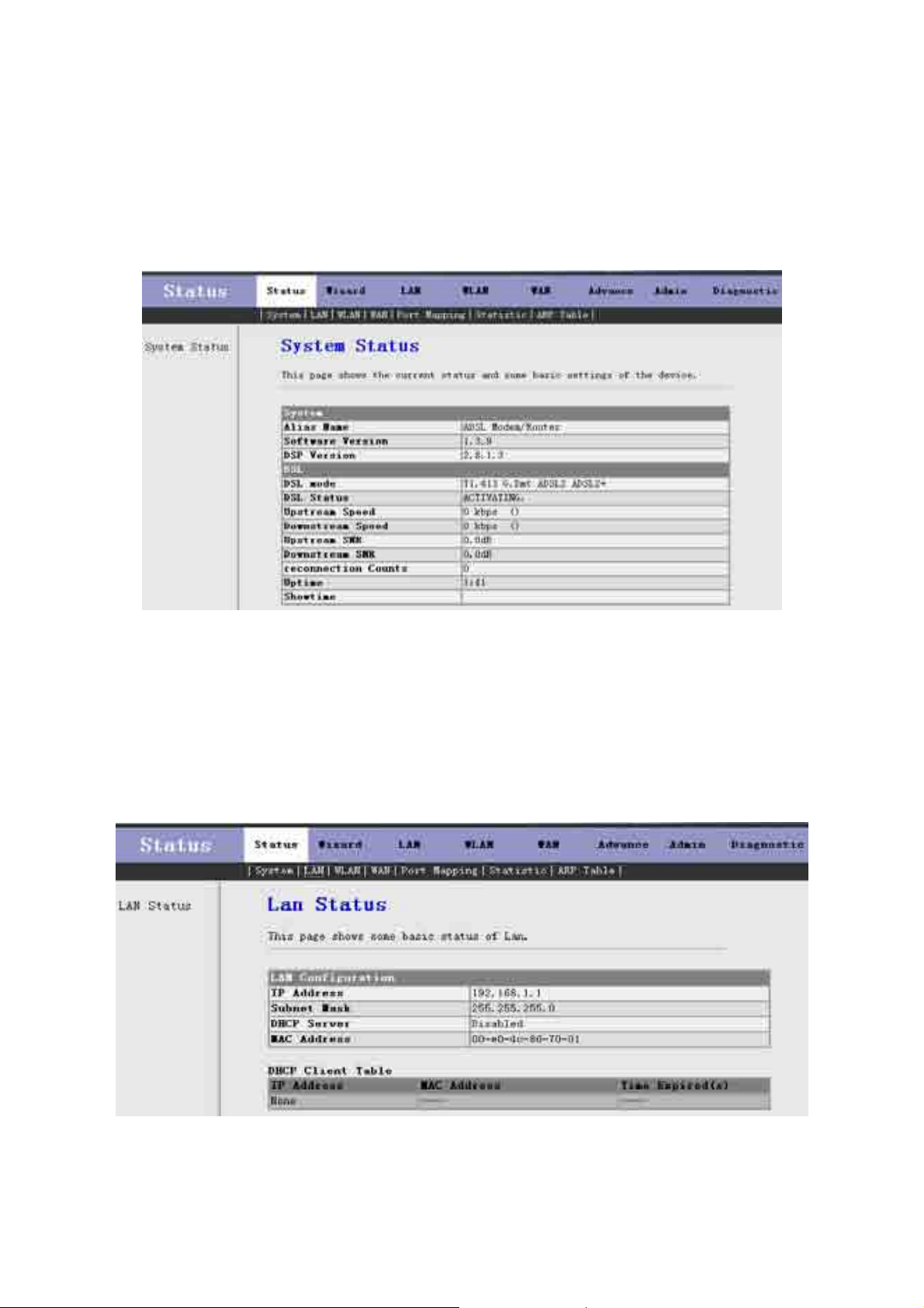
3.2.1 System
Click System in the sub-menu to open the screen of Fig 3.2.1. In this page, you can view the current status and
some basic settings of this router, for example, Software Version, DSL mode, Upstream Speed, Downstream
Speed, Uptime and so on.
Fig 3.2.1
3.2.2 LAN
Click LAN in the sub-menu to open the screen of Fig 3.2.2. In this page, you can view the LAN IP, DHCP
Server status, MAC Address and DHCP Client Table. If you want to config the LAN network, refer to chapter
3.4.1 “LAN Settings”.
Fig 3.2.2
9

3.2.3 WLAN
Click LAN in the sub-menu to open the screen of Fig 3.2.3. In this page, you can view the parameters of the
WLAN.
Fig 3.2.3
3.2.4 WAN
Click WAN in the sub-menu to open the screen of Fig 3.2.4. In this page, you can view basic status of WAN,
Default Gateway, DNS Server, etc. If you want to config the WAN network, refer to chapter 3.6.1 “WAN
Interface”.
10

Fig 3.2.4
3.2.5 Statistic
Click Statistic in the sub-menu to open the menu in the left bar, whick contains two items: Traffic Statistic and
DSL Statistic.
3.2.5.1 Traffic Statistic
Click Traffic Statistic in the left bar to open the screen of Fig 3.2.5.1. In this page, you can view the statistics of each
network port.
Fig 3.2.5.1
3.2.5.2 DSL Statistic
Click DSL Statistic in the left bar to open the screen of Fig 3.2.5.2. In this page, you can view the ADSL line
statistics, downstream rate, upstream rate, etc.
11

Fig 3.2.5.2
3.2.6 ARP Table
Click ARP Table in the sub-menu to open the screen of Fig 3.2.6. In this page, you can view the talbe which shows a
list of learned MAC addresses.
Fig 3.2.6
3.3 Wizard
Click Wizard in the menu to open the sub-menu which contains one item: Wizard.
12

3.3.1 Wizard
Wizard enables speedy and accurate configuration of your Internet connection and other important parameters.
The following sections describe these various configuration parameters. Whether you configure these parameters
or use the default ones, click 'Next' to enable your Internet connection.
When subscribing to a broadband service, you should be aware of the method by which you are connected to the
Internet. Your physical WAN device can be either Ethernet, DSL, or both. Technical information regarding the
properties of your Internet connection should be provided by your Internet Service Provider (ISP). For example,
your ISP should inform you whether you are connected to the Internet using a static or dynamic IP address, or
what protocols, such as PPPOA or PPPoE, you will be using to communicate over the Internet.
Click Wizard in the sub-menu to open the screen of Fig 3.3.1-1. In this page, you can config the VPI/VCI
number.
Fig 3.3.1-1
Be sure to use the correct Virtual Path Identifier (VPI) and Virtual Channel Identifier (VCI) numbers assigned to
you. The valid range for VPI is 0 to 255 and for VCI is 32 to 65535(0 to 31 is reserved for local management of
ATM traffic).
Then press Next, the Fig 3.3.1-2 screen will appear. In this page, you can select the WAN Connect Type and the
encapsulation method.
13
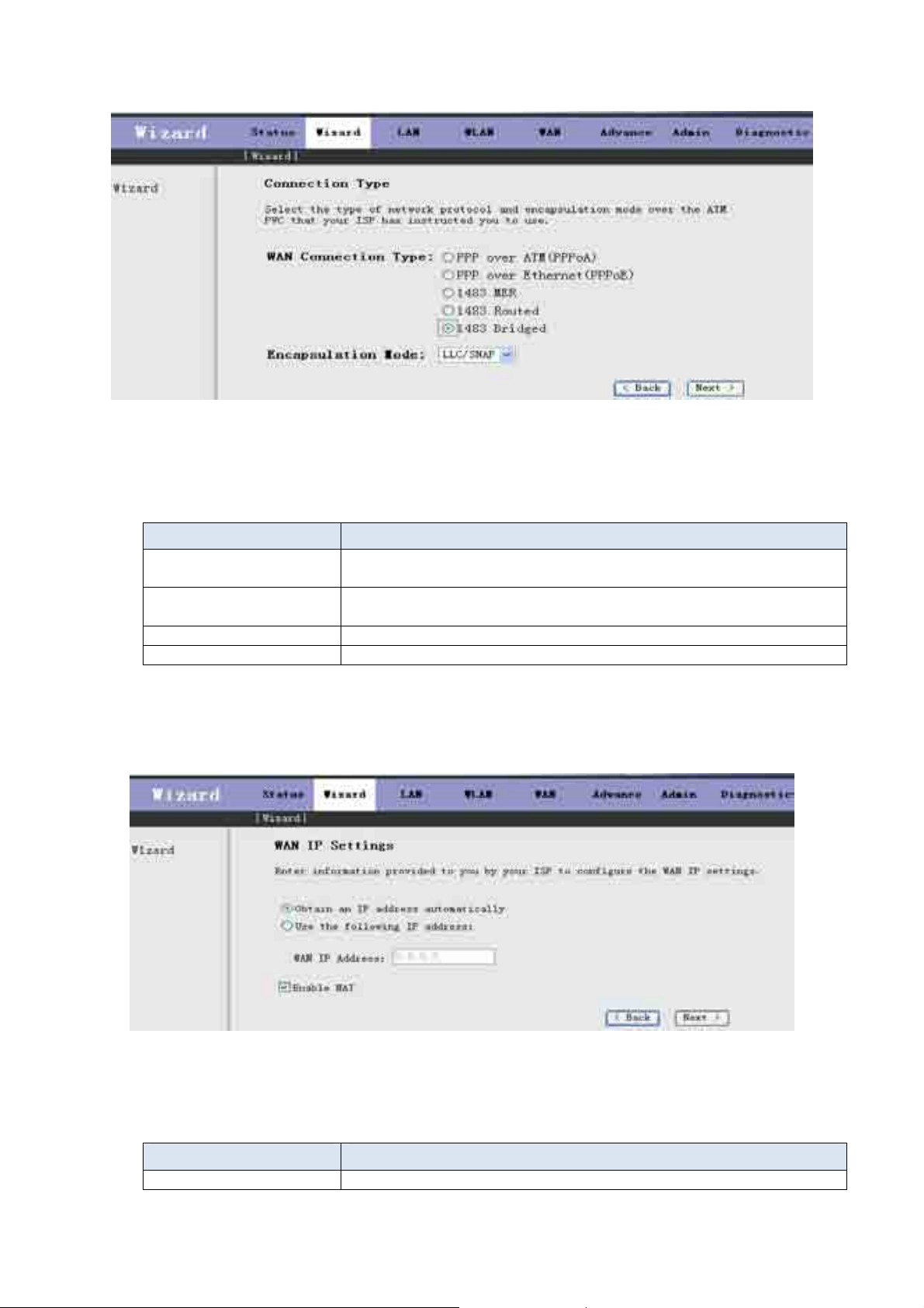
Fig 3.3.1-2
The following table describes the fields in this screen.
Label Description
WAN Connection Type Select the WAN Connection Type here, you can select PPPoA, PPPoE,
1483 MER, 1483 Routed or 1483 Bridged.
Encapsulation Mode Select the method of encapsulation used by your ISP from the drop-down
list box. Choises are LLC/SNAP or VC-Mux.
< Back Click < Back to return to the previous screen
Next > Click Next > to go to the next screen
If you select PPPoA or PPPoE in WAN Connection Type, click Next, the screen of Fig 3.3.1-3 appears as
shown next.
Fig 3.3.1-3
The following table describes the fields of this screen.
Label Description
Obtain an IP address The dynamic IP is not fixed; your ISP assigns you the different one each
14

automatically time.
Use the following IP
A static IP is a fixed IP that your ISP gives you.
address
WAN IP Address Input the IP address of the WAN interface provided by your ISP
Enable NAT Select it to enable the NAT functions of the MODEM. If you are not to
enable NAT and intend the user of the MODEM to access the Internet
normally, you must add a route on the uplink equipment; otherwise the
access to the Internet will fail. Normally, it is required to enable NAT.
< Back Click < Back to return to the previous screen
Next > Click Next > to go to the next screen
Then click Next, the screen of Fig3.3.1-4 appears as shown next.
Fig 3.3.1-4
The following table describes the fields of this screen.
Label Description
PPP Username
PPP Password
The username and password apply to PPPoE and PPPoA encapsulation
only. Make sure that you have entered the correct username and password.
PPP Connection Type Choices are Continuous, Connect on Demand and Manual.
< Back Click < Back to return to the previous screen
Next > Click Next > to go to the next screen
Then click Next, the screen of Fig3.3.1-5 appears as shown next.
15

Fig 3.3.1-5
The following table describes the fields of this screen.
Label Description
LAN IP Enter the IP address of your ROUTER in dotted decimal notation, for
example, 192.168.1.1(factory default)
LAN Netmask Type the subnet mask of LAN IP.
Enable Secondary IP Select this check box to enable the secondary LAN IP
Secondary LAN IP Enter the secondary IP address of your ROUTER in dotted decimal
notation, for example, 192.168.100.1(factory default)
Secondary LAN Netmask Type the subnet mask of the secondary LAN IP
Enable DHCP Server Select this check box to enable the DHCP Server
Start IP This field specifies the first of the contiguous addresses in the IP address
pool.
End IP This field specifies the last of the contiguous addresses in the IP address
pool.
< Back Click < Back to return to the previous screen
Next > Click Next > to go to the next screen
If you finish the settings of this page, click Next, the screen appears as shown next.
16

Fig 3.3.1-7
If you select 1483 MER in Fig 3.3.1-2, the screen appears as shown next.
Fig 3.3.1-8
The following table describes the fields of this screen.
17

Label Description
Obtain an IP address
automatically
The MODEM will obtain a (WAN) IP address automatically and at this
time it will enable DHCP Client functions. The WAN IP address is
obtained from the uplink equipment like BAS and the uplink equipment is
required to enable the DHCP Server functions.
Use the following IP
address
If you want to input the WAN ip address by yourself. Check this entry and
then input related data in the field.
WAN IP Address Input the IP address of the WAN interface provided by your ISP
WAN Subnet Mask Input the subnet mask concerned to the IP address of the WAN interface
provided by your ISP.
Default Gateway You can input the IP address of the default gateway by yourself, click this
entry and then input related data in the fields.
Obtain DNS server
addresses automatically
Use the following DNS
server addresses
To obtain the IP address of the DNS server assigned by the uplink
equipment such as BAS.
If you want to input the IP address of the DNS server by yourself, click
this entry and then input related data in the fields.
Primary DNS server Input the IP address of the primary DNS server here.
Secondary DNS server Input the IP address of the secondary DNS server provided by your ISP
here.
Enable NAT Select it to enable the NAT functions of the MODEM. If you are not to
enable NAT and intend the user of the MODEM to access the Internet
normally, you must add a route on the uplink equipment; otherwise the
access to the Internet will fail. Normally, it is required to enable NAT.
< Back Click < Back to return to the previous screen
Next > Click Next > to go to the next screen
If you finish the settings of this page, click Next, the screen of Fig 3.3.1-6 appears. The settings of this screen see
above paragraphs.
If you select 1483 Routed in Fig 3.3.1-2, the screen of Fig 3.3.1-9 appears as shown next.
Fig 3.3.1-9
18

The following table describes the fields of this screen.
Label Description
None
Obtain an IP address
automatically
Use the following IP
address
WAN IP Address Input the IP address of the WAN interface provided by your ISP
WAN Subnet Mask Input the subnet mask concerned to the IP address of the WAN interface
Obtain DNS server
addresses automatically
Use the following DNS
server addresses
Primary DNS server Input the IP address of the primary DNS server here.
Secondary DNS server Input the IP address of the secondary DNS server provided by your ISP
Enable NAT Select it to enable the NAT functions of the MODEM. If you are not to
< Back Click < Back to return to the previous screen
Next > Click Next > to go to the next screen
The dynamic IP is not fixed; your ISP assigns you the different one each
time.
A static IP is a fixed IP that your ISP gives you.
provided by your ISP.
To obtain the IP address of the DNS server assigned by the uplink
equipment such as BAS.
If you want to input the IP address of the DNS server by yourself, click
this entry and then input related data in the fields.
here.
enable NAT and intend the user of the MODEM to access the Internet
normally, you must add a route on the uplink equipment; otherwise the
access to the Internet will fail. Normally, it is required to enable NAT.
3.4 LAN
Click LAN in the menu to open the sub-menu which contains 2 items: LAN Settings and DHCP Settings. You can
use the LAN configuration to define an IP address for the DSL Router and configure the DHCP server.
3.4.1 LAN Settings
On this screen you can change the device's IP address. The preset IP address is 192.168.1.1. This is the Private IP
address of the DSL Router. This is the address under which the device can be reached in the local network. It can
be freely assigned from the block of available addresses.
Click LAN Settings in the sub-menu to open the screen of Fig 3.4.1. In this page you can config the LAN
network.
19

Fig 3.4.1
The following table describes the fields of this screen.
Label Description
IP Address Input the IP of Local area network interface here.
Subnet Mask We recommend that you use an address from a block that is reserved for
private use. This address block is 192.168.1.1- 192.168.255.25 4
Secondary IP Select this checkbox to enable the secondary LAN IP. The two LAN IP
must be in the different network.
Apply Changes Click this button to save the settings of this page.
3.4.2 DHCP Settings
DHCP (Dynamic Host Configuration Protocol) allows the individual client (computers) to obain the TCP/IP
configuration at start-up from the centralize DHCP server. You can configure this router as a DHCP server or
disable it. DHCP server can assign IP address, an IP default gateway and DNS server to DHCP clients. This
router can also act as a surrogate DHCP server (DHCP Proxy) where it relays IP address assignment from an
actual real DHCP server to clients.
If the DHCP was disabled, the screen of Fig 3.4.2-1 appears. You can enable/disable DHCP Server or DHCP Proxy.
20
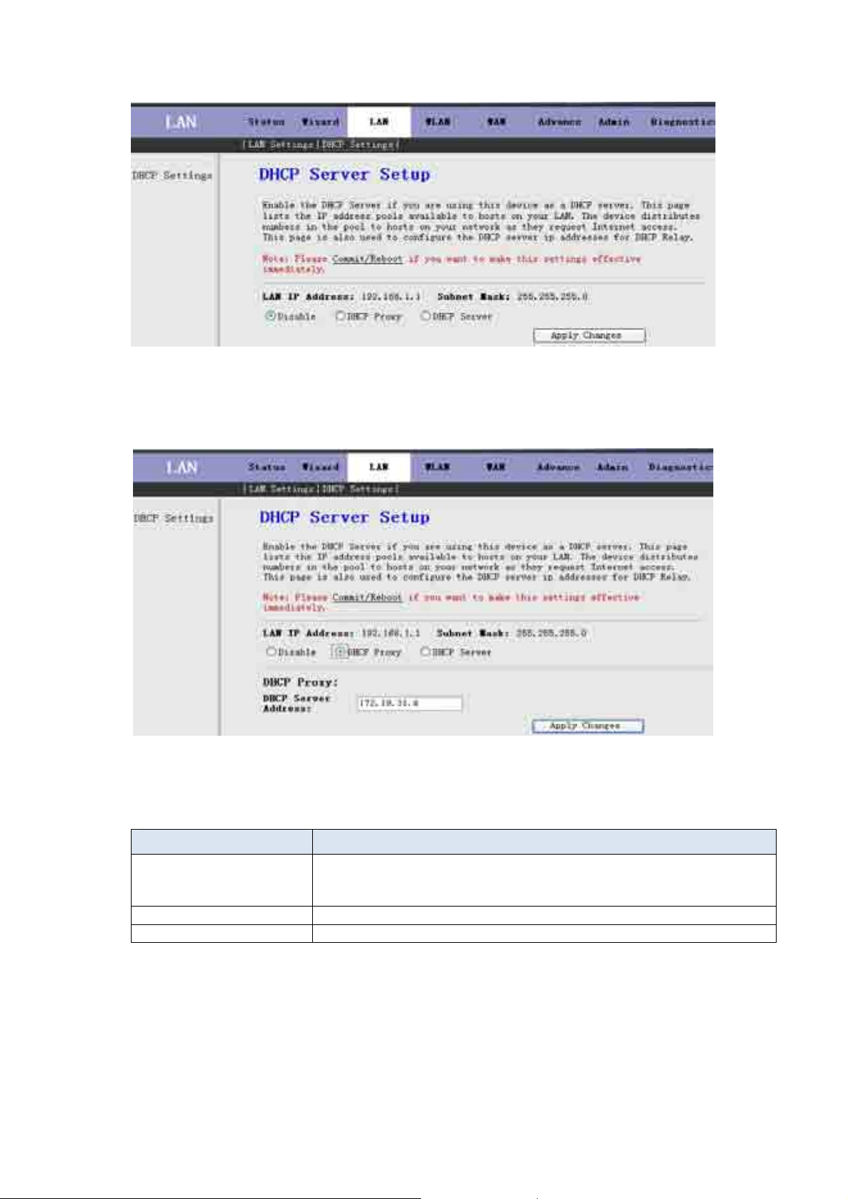
Fig 3.4.2-1
If you set to DHCP Proxy, the screen of Fig 3.4.2-2 appears.
Fig 3.4.2-2
The following table describes the fields of this screen.
Label Description
DHCP Proxy If set to DHCP Proxy, your ROUTER acts a surrogate DHCP Server and
relays the DHCP requests and reponses between the remote server and the
client.
DHCP Server Address Enter the IP address of the actual, remote DHCP server in this field.
Apply Changes Click this button to save the changes of this page.
If you set to DHCP Server, the screen of Fig3.4.2-3 appears as shown next.
21

Fig 3.4.2-3
The following table d e scribes the fields in this screen.
Label Description
DHCP Server If set to DHCP Server, your ROUTER can assign IP addresses, an IP
default gateway and DNS Servers to Windows95, Windows NT and other
systems that support the DHCP client.
IP Pool Range This field specifies the first and the last of contiguous IP address of the IP
address pool.
Show Client Click this button, the screen of Fig 3.5.2-4 appears, which shows the
assigned IP address of the clients.
Max Lease Time The Lease time determines the period for which the PCs retain the IP
addresses assigned to them without changing them.
Domain Name Input the domain name here if you know. If you leave this blank, the
domain name obtained by DHCP from the ISP is used. While you must
enter host name(System Name) on each individual computer, the domain
name can be assigned from this router via DHCP server.
Gateway Address Enter the IP default gateway of the IP address pool.
MAC-Base Assignment Click this button, the screen of Fig3.5.2-5 appears. T his function allows
you assign IP addresses on the LAN to specific individual computers
based on their MAC address.
Apply Changes Click this button to save the changes of this page.
Click Show Client, the following window appears. In this window, you can view the IP address assigned to each
DHCP client.
22

Fig 3.4.2-4
The following table describes the fields in this screen.
Label Description
IP Address This field displays the IP address relative to the MAC address.
MAC Address This field displays the MAC(Media Access Control) address of the
computer.
Every Ethernet device has a unique MAC address. The MAC address is
assigned at the factory and consists of six pairs of hexadecimal character,
for example, 00-A0-C5-00-02-12.
Time Expired(s) Here shows the lease time. The Lease time determines the period for
which the PCs retain the IP addresses assigned to them without changing
them.
Refresh Click this button to refresh the Active DHCP Client Table.
Close Click this button to close this window.
Click MAC-Base Assignment button, the below window appears. In this page, you can assign IP
addresses on the LAN to specific individual computers based on their MAC address.
Fig 3.4.2-5
23

The following table describes the fields of this screen.
Label Description
Host MAC Address Type the MAC address of a computer on your LAN
Assigned IP Address This field specifics the IP of the IP address pool.
Assign IP Click this button after entered Host MAC Address and Assigned IP
Address, a row will be added in MAC-Base Assignment T able.
Modify Assigned IP Select a row in MAC-Base Assignment T able, the MAC address and IP
address will appears Host MAC Address and Assigned IP Address.
After modified the MAC Address and IP Address, click this button to save
the changes.
Delete Assigned IP Select a row in MAC-Base Assignment Table, then clic k this bu tto n, t his
row will be deleted.
Close Click this button to close this window.
MAC-Base Assignment
Table
This table shows the assigned IP address based on the MAC address.
3.5 WLAN
Click WLAN in the menu to open the sub-menu which contains 5 items: Basic Settings, Security, Advance
Settings, Access Control and WDS Settings.
This session introduces the wireless LAN and some basic configurations. Wireless LANs can be as simple as
tow computers with wireless LAN cards communicating in a pear-to-pear network or as complex as a number of
computers with wireless LAN cards communicating through Access Points which bridge network traffic to
wired LAN.
3.5.1 Basic Settings
Click Basic Settings in the sub-menu to open the screen of Fig 3.5.1-1. This page is used to configure the parameters
for wireless LAN clients who may connect to your Access Point.
24

Fig 3.5.1-1
The following table describes the fields of this screen.
Label Description
Disable Wireless LAN
Interface
The wireless LAN is turned on by default. Select the check box
to disable the wireless LAN.
(Root)SSID The SSID(Service Set Identification) is a unique name to
identify the ROUTER in the wireless LAN. Wireless stations
associating to ROUTER must have the same SSID.
Enter a desciptive name.
Virtual SSID
Set VSSID
You can enable 4 SSID at most. Click Set VSSID, the screen of
Fig3.6.1-2 appears.
SSID You can enable or disable this SSID.
Country/Area Select the region where you are.
Channel Number A channel is the radio frequency(ies) used by 802.11b/g wireless
device. Channels available depend on your geographical area. You
may have a choice of channels(for your region) so you should use
a different channel than an adjacent AP(Access Point) to reduce
interference. Interference occurs when radio signal from
diffirent access point overlap causing interference and
degrading performance.
Select a channel from the drop-down list box.
Apply Changes Click this button to save the changes of this page.
25

Fig 3.5.1-2
The following table describes the fields of this screen.
Label Description
SSID The SSID(Service Set Identification) is a unique name to identify the
ROUTER in the wireless LAN
Apply Changes Click this button to save the changes of this page.
Undo Click this button to begin configuring this screen afresh.
3.5.2 Security
Click Security in the sub-menu to open the screen of Fig 3.5.2-1. Wireless security is vital to your network to
pretect wireless communication between wireless stations, access points and wired network.
26

Fig 3.5.2-1
The following table describes the fields of this screen.
Label Description
SSID Type Select the SSID here.
Encryption Choices are None, WEP, WPA(TKIP), WPA2(AES) and WPA2 Mixed.
WEP(Wired Equivalent Privacy) entrypts data frames before transmitting
over the wireless network.
WPA(Wi-Fi Protected Access) is a subset of the IEEE802.11i security
specification draft. Key differences between WPA and WEP are user
authentication and improved data encryption.
Set WEP Key This button is available when you set to WEP. Click this button, the
screen of Fig3.6.2-2 appears.
Authentication RADIUS
Server
RADIUS is based on a client-server model that supports authentication,
authorization and accounting. The access point is client and the server is
RADIUS server. RADIUS is a simple package exchange in which your
ROUTER acts as a message relay between wireless station and the
network RADIUS server.
Port The default port of the RADIUS server for authentication is 1812. You
need not change this value unless your network administrator instructs you
to do so with additional information.
IP Address Enter the IP address of the RADIUS server.
Password Enter a password as the key to be shared between the external
authentication server and the access point. The key is not send over the
network. This key must be the same on the external authentication server
and your ROUTER.
Apply Changes Click this button to save the the changes of this page.
27

Fig 3.5.2-2
The following table describes the fields of this screen.
Label Description
SSID Type Select the SSID here.
Key Length Select 64-bit or 128-bit to use data encryption.
Key Format If you chose 64-bit, you can choose ASCII(5 characters) or Hex(10
characters).
If you chose 128-bit, you can choose ASCII(13 characters) or Hex(26
characters).
Default Tx Key Select the default Encryption Key here.
Encryption Key 1 to 4 The Encryption keys are used to encrypt data. Both ROUTER and wireless
stations must use the same Encryption Key for data transmission.
If you chose 64-bit and ASCII(5 characters), then enter any 5 ASCII
characters.
If you chose 64-bit and Hex(10 characters), then enter any 10
hexadecimal characters.
If you chose 128-bit and ASCII(13 characters), then enter any 13 ASCII
characters.
If you chose 128-bit and Hex(26 characters), then enter any 26
hexadecimal characters.
Apply Changes Click this button to save the changes of this page.
Close Click this button to close this window.
Undo Click this button to begin configuring this screen afresh.
3.5.3 Advance Settings
Click Advance Settings in the sub-menu to open the screen of Fig 3.5.3. These settings are only for more
technically advanced users who have a sufficient knowledge about wireless LAN. These settings should not be
changed unless you know what effect the changes will have on your Access Point.
28

Fig 3.5.3
The following table describes the fields of this screen.
Label Description
Fragment Threshold This is the maximum data fragment size(between 256 and 2346bytes) that
can be sent in the wireless network before the ROUTER will fragment the
packet into smaller data frames.
RTS Threshold RTS(Request To Send) is designed to prevent collisions due to hidden
node. A RTS defines the biggest size data frame you can send before a
RTS(Request To Send) handshake invoked. The RTS Threshold value is
between 0 and 2347.
If the RTS Threshold value is greater than Fragment Threshold value,
then the RTS hankshake will never occur as the data frames will be
fragmented before they reach RTS size.
Apply Changes Click this button to save the changes of this page.
3.5.4 Access Control
Click Access Control in the sub-menu to open the screen of Fig 3.5.4. In this page, you can configure the
Wireless Access Control.
29

Fig 3.5.4
The following table describes the fields of this screen.
Label Description
Select Access Control
Mode
Choises are Disable, Allow Listed and Deny Listed. Select Allow Listed
to block access to the router, MAC addresses not listed will be allowed to
access your router. Select Deny Listed to permit access to the router,
MAC addresses not listed will be denied to access your router.
Apply Changes Click this button to save the change of Select Access Control Mode.
MAC Addr Enter the MAC address(in XX-XX-XX-XX-XX-XX format) of the
wireless station that are allowed or denied access to your router in this
address field.
Apply Changes Click this button, the MAC Addr will be added to Current Access
Control List.
Reset Click this button to begin configuring the MAC Addr afresh.
Current Access Control
List
The MAC address in this table will be allowed or denied access to the
router.
Delete Click this button to delete the row you select in the Current Access
Control List.
Delete All Click this button to delete all rows in the Current Access Control List.
Reset Click this button to begin configuring the Current Access Control List
afresh.
3.5.5 WDS Settings
Click WDS Settings in the sub-menu to open the screen of Fig 3.5.5. Wireless Distribution System is commonly used
in areas requiring multiple APs, where wiring is not possible or costly and for providing back-up paths between APs.
Notice: You must select the “AP+WDS” option in chapter 3.6.1 before you configure this page.
30

Fig 3.5.5
The following table describes the fields of this screen.
Label Description
Enable WDS Select this check box to enable the WDS function, or you can’t configure
this page.
MAC Addr Enter the MAC address(in XX-XX-XX-XX-XX-XX format) of the AP.
Comment Enter the comment to describe the AP of the MAC Addr.
Apply Change Click this button to add the MAC Addr with the Comment to Current
WDS AP List.
Reset Click this button to begin configuring the MAC Addr and Comment
afresh.
Current WDS AP List This table shows all APs of the WDS.
Delete Click this button to delete the row of the Current WDS AP List.
Delete All Click this button to delete all rows of the Current WDS AP List.
3.6 WAN
Click WAN Interface in the menu to open the sub-menu which contains 2 items: WAN Interface and ADSL
Settings.
3.6.1 WAN Interface
Click WAN Interface in the sub-menu to open the screen of Fig 3.6.1-1. In this page, you can configure WAN
Interface of your router.
31

Fig 3.6.1-1
Label Description
Current ATM VC Table This table shows the PVCs already existed. It shows the Interface name,
Channel Mode, VPI/VCI, Encapsulation mode, local IP Address, Remote
IP address, etc. The maximum item of this table is eight.
VPI (Virtual Path Identifier) The virtual path between two points in an ATM
network, and its valid value is from 0 to 255
VCI The virtual chann el be tw een two points in an ATM network, ranging from
32 to 65535 (1 to 31 are reserved for known protocols)
Encapsulation Choices are LLC and VC-Mux.
Channel Mode There are five choices: 1483 Bridged, 1483 MER, PPPoE, PPPoA and
1483 Routed.
Admin Status If select Disable, this PVC will be unusable.
Enable NAPT Select it to enable the NAPT functions of the MODEM. If you are not to
enable NAPT and intend the user of the MODEM to access the Internet
normally, you must add a route on the uplink equipment; otherwise the
access to the Internet will fail. Normally, it is required to enable NAPT.
PPP Settings
Login Name The correct user name that your ISP has provided to you.
Password The correct password that your ISP has provided to you
Connection Type The choices are Continuous, Connect on Demand and Manual.
Idle Time(min) If select Connect on Demand, you need to input the idle timeout time.
Within the preset minutes, if the MODEM doesn’t detect the flow of the
user continuously, the MODEM will automatically disconnect the PPPOE
connection.
WAN IP Settings
Type The choices are Fixed IP and Use DHCP. If set Fixed IP, you should
32

enter the Local IP Address, Remote IP Address and Subnet Mask. If set
Use DHCP, your MODEM will be a DHCP client, the WAN IP will be
assigned by the remote DHCP server.
Local IP Address This is the IP of WAN interface which is provided by your ISP.
Remote IP Address This is the gateway IP which is provided by your ISP.
Subnet Mask This is the Subnet Mask of the Local IP Address.
Unnumbered Select this checkbox to enable IP Unnumbered function.
Default Route
Add After configuring the parameters of this page, click this button then a new
PVC will be added into Current ATM VC Table.
Modify Select a PVC in the Current ATM VC Table, then modify the parameters
of this PVC. When you finish, click this button to apply the change of this
PVC.
Delete Select a PVC in the Current ATM VC Table, then click this button to
delete this PVC.
Undo Click this button to begin configuring this screen afresh.
ATM Setting Click this button, the Fig 3.6.1-3 will appear. In this page, you can
configure ATM PVCs’QoS mode. The details, please see the following
pages.
Click this button, the following screens will appear. In these pages, you
can modify the PVCs’ parameters.
If the PVC uses PPPoE mode, click , the Fig 3.6.1-2 will appear. In this page, you can configure this PPPoE
PVC’s parameters.
Fig 3.6.1-2
33

ATM Setting :Click ATM Setting button in Fig3.6.1-1, the screen of
can configure the parameters of the ATM for your ADSL router, include QoS type, PCR,
CDVT, SCR and MBS.
Fig 3.6.1-3
Fig 3.6.1-3 will appear. In this page, you
3.6.2 ADSL Settings
Click ADSL Interface in the sub-menu to open the screen of Fig 3.6.2. In this page, you can select the DSL
modulation. Mostly, the user just need to remain this factory default setting. Our modem support these modulations:
G.Dmt, G.lite, T1.413, ADSL2, ADSL2+, AnnexL and AnnexM. The router will negotiate the modulation mode
with the DSLAM.
Fig 3.6.2
34

3.7 Advance
Click Advance in the menu to open the sub-menu which contains 8 items: DNS, Firewall, Virtual Server,
Routing, IP QOS, Anti-dos, Port Mapping and Others.
3.7.1 DNS
Short for Domain Name System (or Service or Server), an Internet service that translates domain names into IP
addresses. Because domain names are alphabetic, they're easier to remember. The Internet however, is really based on
IP addresses. Every time you use a domain name, therefore, a DNS service must translate the name into the
corresponding IP address. For example, the domain name www.example.com might translate to 198.105.232.4.
The DNS system is, in fact, its own network. If one DNS server doesn't know how to translate a particular domain
name, it asks another one, and so on, until the correct IP address is returned.
Click DNS in the sub-menu to open the screen of Fig 3.7.1.
Fig 3.7.1
Label Description
Attain DNS Automatically When this checkbox is selected, this router will accept the first received
DNS assignment from one of the PPPoA, PPPoE or MER enabled PVC(s)
during the connection establishment.
Set DNS Manually When this checkbox is selected, please enter the primary and optional
secondary DNS server IP addresses.
Apply Changes Click this button to save the settings of this page.
Reset Selected Click this button to begin configuring this screen afresh.
3.7.2 Firewall
Click Firewall in the sub-menu to open the menu in the left bar, whick contains three items:IP\Port Fileter, MAC
Filter and URL Blocking.
35

3.7.2.1 IP\Port Filter
Click IP\Port Filter in the left bar to open the screen of Fig 3.7.2.1. Entries in this table are used to restrict certain
types of data packets through the Gateway. Use of such filters can be helpful in securing or restricting your local
network.
Click the button Apply Changes to save the settings of this page.
Click the button Add Rule to add a new rule of the IP\Port Filter.
Fig 3.7.2.1
3.7.2.2 MAC Filter
Click MAC Filter in the left bar to open the screen of Fig 3.7.2.2. Entries in this table are used to restrict certain types
of data packets from your local network to Internet through the Gateway. Use of such filters can be helpful in securing
or restricting your local network.
Click the button Apply Changes to save the settings of this page.
Click the button Add Rule to add a new rule of the MAC Filter.
36

Fig 3.7.2.2
3.7.2.3 URL Blocking
Click URL Blocking in the left bar to open the screen of Fig 3.7.2.3. This page is used to configure the Blocked
FQDN(Such as tw.yahoo.com) and filtered keyword. Here you can add/delete FQDN and filtered keyword.
Fig 3.7.2.3
37

3.7.3 Virtual Server
Click Virtual Server in the sub-menu to open the menu in the left bar,whick contains two items:Services and DMZ
Settings.
3.7.3.1 Services
Click Services in the left bar to open the screen of Fig 3.7.3.1. This page is used to enable the servers in the local
network.
Click the button Add to add a virtual server.
Fig 3.7.3.1
3.7.3.2 DMZ Settings
Click DMZ Settings in the left bar to open the screen of Fig 3.7.3.2. A Demilitarized Zone is used to provide
Internet services without sacrificing unauthorized access to its local private network. Typically, the DMZ host
contains devices accessible to Internet traffic, such as Web (HTTP ) servers, FTP servers, SMTP (e-mail) servers
and DNS servers.
Select the checkbox Enable DMZ to enable this function. Then input a IP Address of the DMZ host.
Click the button Apply Changes to save the settings of this page.
38

Fig 3.7.3.2
3.7.4 Routing
Click Routing in the sub-menu to open the menu in the left bar, whick contains two items:RIP and Static
Route.
3.7.4.1 RIP
Click RIP in the left bar to open the screen of Fig 3.7.4.1. Enable the RIP if you are using this device as a
RIP-enabled router to communicate with others using the Routing Information Protocol. This page is used to select the
interfaces on your deviceis that use RIP, and the version of the protocol used.
Fig 3.7.4.1
39

3.7.4.2 Static Route
Click Static Route in the left bar to open the screen of Fig 3.7.4.2-1. This page is used to configure the routing
information. Here you can add/delete IP routes.
Fig 3.7.4.2-1
Click the button Show Routes, the below window will appear. The table shows a list of destination routes
commonly accessed by your network.
Fig 3.7.4.2-2
3.7.5 IP QoS
Click Anti-dos in the sub-menu to open the screen of Fig 3.7.5. Entries in this table are used to assign the
precedence for each incoming packet based on physical LAN port, TCP/UDP port number, and
source/destination IP address/subnet masks.
40

Fig 3.7.5
3.7.6 Anti-dos
Click Anti-dos in the sub-menu to open the screen of Fig 3.7.6. "denial-of-service attack"(DoS Attack) a type of
attack on a network that is designed to bring the network to its knees by flooding it with useless traffic. In this
page, you can configure to prevent DOS attacks.
Click the button Apply Changes to save the settings of this page.
Fig 3.7.6
41

3.7.7 Other
Click Others in the sub-menu to open the menu in the left bar,whick contains four items:IGMP Prox y, UPNP,
Bridge and IP PassThrough.
3.7.7.1 IGMP Proxy
Click IGMP Proxy in the left bar to open the screen of Fig 3.7.7.1. IGMP proxy enables the system to issue IGMP
host messages on behalf of hosts that the system discovered through standard IGMP interfaces. The system acts as a
proxy for its hosts after you enable it.
Click Apply Changes to save the settings of this page.
Fig 3.7.7.1
3.7.7.2 UPNP
Click UPNP in the left bar to open the screen of Fig 3.7.7.2. This page is used to configure UPnP. The system
acts as a daemon after you enable it.
Click Apply Changes to save the settings of this page.
42

Fig 3.7.7.2
3.7.7.3 Bridge
Click Bridge in the left bar to open the screen of Fig 3.7.7.3-1. This page is used to configure the bridge
parameters. Here you can change the settings or view some information on the bridge and its attached ports.
Fig 3.7.8.3-1
Click Show MACs button in Fig 3.7.7.3-1, the below window will appear. This table shows a list of learned
MAC addresses for this bridge.
43

Fig 3.7.7.3-2
3.7.7.4 IP PassThrough
Click IP PassThrough in the left bar to open the screen of Fig 3.7.7.4. The IP PassThrough has the other name ZIPB
or IP Extension. In this page, you can enable and configure IP PassThrough function.
Fig 3.7.7.4
3.8 Admin
Click Admin in the menu to open the sub-menu which contains 11 items: Remote Access, Commit/Reboot,
Password, Backup/Restore, Upgrade Fireware, Time Zone, System Log, SNMP, TR069, ACL and Logout.
3.8.1 Remote Access
Click Remote Access in the sub-menu to open the screen of Fig 3.8.1. In this page, you can enable or disable the
services which will be used by remote host. For example, if TELNET service is enabled and port is 23, the remote host
can access this router by telnet through port 23.
44

Fig 3.8.1
3.8.2 Commit/Reboot
Click Commit/Reboot in the sub-menu to open the screen of Fig 3.8.2. In this page, you can set the router reboot
to default settings or set the router save the current settings then reboot.
Fig 3.8.2
Label Description
Reset to default settings Select this checkbox to reset router to default settings.
Commit current settings Select this checkbox to save the current settings and reboot router.
Reboot Click this button to reboot the router according to the above option.
3.8.3 Password
Click Login Password in the sub-menu to open the screen of Fig 3.8.3. In this page, you can change the
password of the user, include admin and user.
the The common user name and password are user/user.
The super user name and password are admin/admin as default, and
45

Label Description
Fig 3.8.3
User Name Select the user name in the drop-down list box. The choices are admin
and user.
Old Password Af ter selecte d the user name, input the old password of the user here.
New Password Input the new password what you want to set of the user.
Confirmed Password Input the new password again.
Apply Changes Click this button to save the settings of this page.
Reset Click this button to begin configuring the password afresh.
3.8.4 Backup/Restore
Click Backup/Restore in the sub-menu to open the screen of Fig 3.8.4. In this page, you can backup the current
settings to a file and restore the settings from the file which was saved previously.
IMPORTANT! Do not turn off your router or press the Reset button while these procedures are in progress.
Fig 3.8.4
46

Label Description
Save Settings to File Click the Save button, then select the path and save the configuration file
of your router.
Load Settings from File Click the Browse button to select the configuration file.
Upload Selected the configuration file of router, click Upload button to begin
restore the router configuration.
3.8.5 Upgrade Fireware
Click Upgrade Fireware in the sub-menu to open the screen of Fig 3.8.5. In this page, you can upgrade the
fireware of this router.
IMPORTANT! Do not turn off your router or press the Reset button while this procedure is in progress.
Fig 3.8.5
Label Description
Select File Click the Browse button to select the Fireware file.
Upload Selected the Fireware file, click Upload button to beg in upgrading the
Fireware.
Reset Click this button to begin selecting the Fireware file afresh.
3.8.6 Time Zone
Click Time Zone in the sub-menu to open the screen of Fig 3.8.6. In this page, you can set the system time manually
or get the system time from the time server.
47

Fig 3.8.6
Label Description
Refresh Click this button to refresh the system shown in the page.
Time Mode If select Time Server, the router will get the system time from the time
server. If select Manual, you should configure the system time manually.
Enable SNTP Client
Update
If select this checkbox, you can choose the correct SNTP Server which
you want.
SNTP Server Choose the SNTP Server here.
Time Zone Select the Time Zone of in which area you are.
Apply Changes Click this button to save the settings of this page.
3.8.7 System Log
Click System Log in the sub-menu to open the screen of Fig 3.8.7. In this page, you can enable or disabled the
System log function, view the system log.
48

Fig 3.8.7
Label Description
System Log You can enable or disable the System Log function.
Apply Changes Click this button to save the settings of this page.
Refresh Click this button to refresh the system log shown in the textfield.
3.8.8 SNMP
Click SNMP in the sub-menu to open the screen of Fig 3.8.8. In this page, you can set the SNMP parameters.
Label Description
Fig 3.8.8
49

Trap IP Address Input the Trap Host’s IP here. The trap information will be sent to this
host.
Community name(read-only)
Community name(write-only)
Apply Changes Click this button to save the settings of this page.
Reset Click this button to begin configuring this screen afresh.
The network administrators must use this password to read the
information of this router.
The network administrators must use this password to configure
the information of this router.
3.8.9 TR069
Click ACL in the sub-menu to open the screen of Fig 3.8.9. In this page, you can configure the TR-069 CPE.
Fig 3.8.9
50

3.8.10 ACL
Click ACL in the sub-menu to open the screen of Fig 3.8.10. In this page, you can configure the IP Address for
Access Control List.
Step 1: If you want to enable ACL, please choose "Enable" then press "Apply Changes";
Step 2: Config Access Control List;
Step 3: Press "take effect" to effect the configuration.
Note: If you check "Enable" in ACL Capability, please make sure that your host IP is in ACL List before it takes
effect
If ACL enabled, only the effective IP in ACL can access ADSL Router.
Fig 3.8.10
3.9 Diagnostic
Click Diagnostic in the menu to open the sub-menu which contains 4 items: Ping, ATM Loopback, ADSL and
Diagnostic.
3.9.1 Ping
Click Ping in the sub-menu to open the screen of Fig 3.9.1.
51

Fig 3.9.1
Label Description
Host Address Enter the IP Address here.
Go! Click this button to begin to Ping the Host Address.
3.9.2 ATM Loopback
Click ATM Loopback in the sub-menu to open the screen of Fig 3.9.2. In this page, you can use VCC loopback
function to check the connectivity of the VCC.
Fig 3.9.2
Go! :Click this button to begin testing.
3.9.3 ADSL
Click ADSL in the sub-menu to open the screen of Fig 3.9.3. This page is used for ADSL Tone Diagnostics.
52

Fig 3.9.3
Go! :Click this but t o n t o b egi n A DSL Tone Diagnostics.
3.9.4 Diagnostic
Click Diagnostic in the sub-menu to open the screen of Fig 3.9.4. This page is used for testing your DSL
connection.
Fig 3.9.4
Run Diagnostic Test:Click this button to begin testing.
53

 Loading...