

Page 1

Page 2

2
Contents
Contents
Guarantee, service, repairs and maintenance
Chapter1: Customer information
General Information on Safety
Chapter2: General description
General description
END USER INSTRUCTIONS
Chapter 3: Receiver
INSTRUCTION GUIDE
Chapter 4: Troubleshooting
Chapter 5: Accessories
Guarantee, service, repairs and maintenance
Inmotion Controls, Inc. products are covered by a guarantee/warranty against material, construction and
manufacturing defects. During the guarantee/warranty period, Inmotion may replace the product or faulty parts.
Work under guarantee/warranty must be carried out by Inmotion Controls, Inc.
The following are NOT covered by the guarantee/ warranty:
▪Faults resulting from normal wear and tear
▪Parts of a consumable nature such as pushbuttons, relays, fuses etc.
▪Products that have been subject to unauthorized modifications
▪Faults resulting from incorrect installation and use
▪Condensation and water damage
Maintenance:
▪Repairs and maintenance must be carried out by qualified personnel.
▪Use spare parts from Inmotion Controls, Inc. only.
▪Contact your representative if you require service or other assistance.
▪Keep the product in a dry, clean place.
▪Keep contacts and antennas clean.
▪Wipe off dust using a slightly damp, clean cloth.
Page 3

3
Chapter 1: Customer Information
Thank you for purchasing an Inmotion Controls, Inc. radio remote control.
READ ALL INSTRUCTIONS CAREFULLY BEFORE MOUNTING, INSTALLING AND
CONFIGURATING THE PRODUCT.
This manual includes general information concerning the operation of the radio remote control transmitter.
General Information on Safety
•Persons under the influence of drugs and/or alcohol and/or other medicine that impairs their reaction may not
assemble, disassemble, install, put into operation, repair or operate the product.
•All conversions and modifications of an installation/system must conform to the relevant safety requirements.
Work on the electrical equipment must be performed only by qualified, authorized personnel and in accordance
with the relevant safety requirements.
•In the event of malfunctioning, visible defects or irregularities, the product must be stopped, switched off and
the relevant master switches must be switched off.
FCC Part 15 (FCC ID: RN489896162JK01)
* This device complies with Part 15 of the FCC Rules. Operation is subject to the following two conditions: (1)
this device may not cause harmful interference and (2) this device must accept any interference received,
including interference that may cause undesired operation.
* You are cautioned that changes or modifications not expressly approved by the party responsible for
compliance could void your authority to operate the equipment.
European Union Regulatory Notice
This device bearing the CE marking is in compliance with the essential requirements and other relevant
provisions of Directive 1999/5/EC. This device complies with the following harmonized European standards.
Safety: EN 60950-1:2006+A11:2009+A1:2010+A12:2011
EMC: ETSI EN30 1489-1 V1.9.2 2001-09; ETSI EN 301 489-3 V1.4.1 2002-08
Radio: ETSI EN 300 220-1 v2.4.1: 2012; ETSI EN 300 220-2 v2.4.1: 2012
The following CE marking is valid for EU harmonized telecom products.
IC Statement (IC: 10821A-8989616201)
This device complies with Industry Canada license-exempt RSS standard(s). Operation is subject to the
following two conditions: (1) this device may not cause interference, and (2) this device must accept any
interference, including interference that may cause undesired operation of the device.
Page 4

4
Chapter 2: General Description
Start/ Horn switch
The K series transmitter has a Start/Horn pushbutton on the left side.
The Start/Horn switch has 2 functions:
1. Press to Start.
2. Press for horn while operating.
Start the transmitter in operating mode
1. Turn to release the Emergency Off button.
2. Press the ”START” button.
Turning the transmitter off
Turn the transmitter off by completely pressing the Emergency Off button.
The transmitter turns off. All relays deactivate.
The K series transmitter comes in different versions, featuring 2, 4, 6, or 8 pushbuttons. The transmitter also
features 2-step pushbuttons. Both steps of each pushbutton can operate different functions like controlling the
speed of a movement, step 1: slow, step 2: fast.
Page 5

5
Chapter 2: General Description
Frequency Range
433.0525~434.7775MHz
Modulation method
4GFSK
Typical operating range
300 feet
Control system
PLL (Phase Lock Loop)
Antenna impedance
50 ohms
Typical response time for commands
50ms~100ms
Power Supply
LR6 (AA) 1.5Volt x 2
Antenna
Internal
Average power consumption
16ma@3VDC (default setting)
Radio-frequency power
<10dBm (default setting)
Operating and storage temperature
-4°F ~ 131°F / -40°F ~ 149°F
Protection rating
IP65
Dimensions
7.63” x 2.25” x 2.00” (2-8 buttons)
Weight (including battery)
Approx. 11.46 ounces
Housing material
PA6 (30% Glass Filled)
Changing the batteries:
BATTERY TYPE: 2 x 1.5V(LR6 AA)
Technical Data
Transmitter
Page 6

6
Chapter 3: Receiver
Frequency
433.0525~434.7775MHz
Modulation Method
4GFSK
Sensitivity
-112dBm@baud 1.2K bps
Control System
PLL
Antenna impedance
50 ohms
Typical response time for commands
50mS ~ 100mS
Power Supply (AC)/Power Consumption
24 ~ 240VAC, 50/60Hz (8.3 Watts)
Power Supply (DC)/Power Consumption
24 ~ 160VDC (12.8 Watts)
Antenna
External
Standby power
<30mA @ 120VAC
Operating and storage temperature
-4°F~131°F/-40°F~149°F
Protection degree
IP 65
Dimensions
7.46” x 7.22” x 2.52”
Weigh
3.95 Lbs.
Housing material
PA6 (30% Glass Filled)
WARNING! The receiver must NOT be opened by any other than a qualified installer. Make sure to turn the
electricity off before opening the receiver.
Technical Data
Receiver
Page 7

7
Chapter 3: Receiver
WARNING! DO NOT FLUSH MOUNT THE RECEIVING ASSEMBLY. PLEASE MAINTAIN
PROPER CLEARANCE AS SHOWN. PLEASE USE THE SUPPLIED MOUNT!
K202 Wiring Diagram
Page 8
8
Chapter 3: Receiver
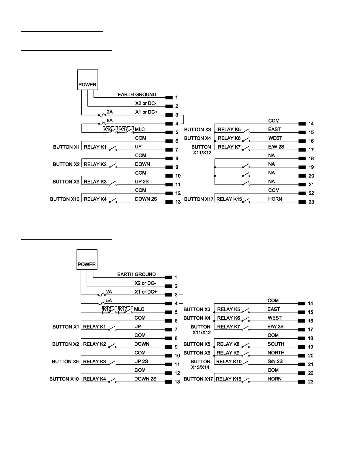
K404 Wiring Diagram
K606 Wiring Diagram
Page 9

9
Chapter 3: Receiver
K806 Wiring Diagram
K808 Wiring Diagram
Page 10
10
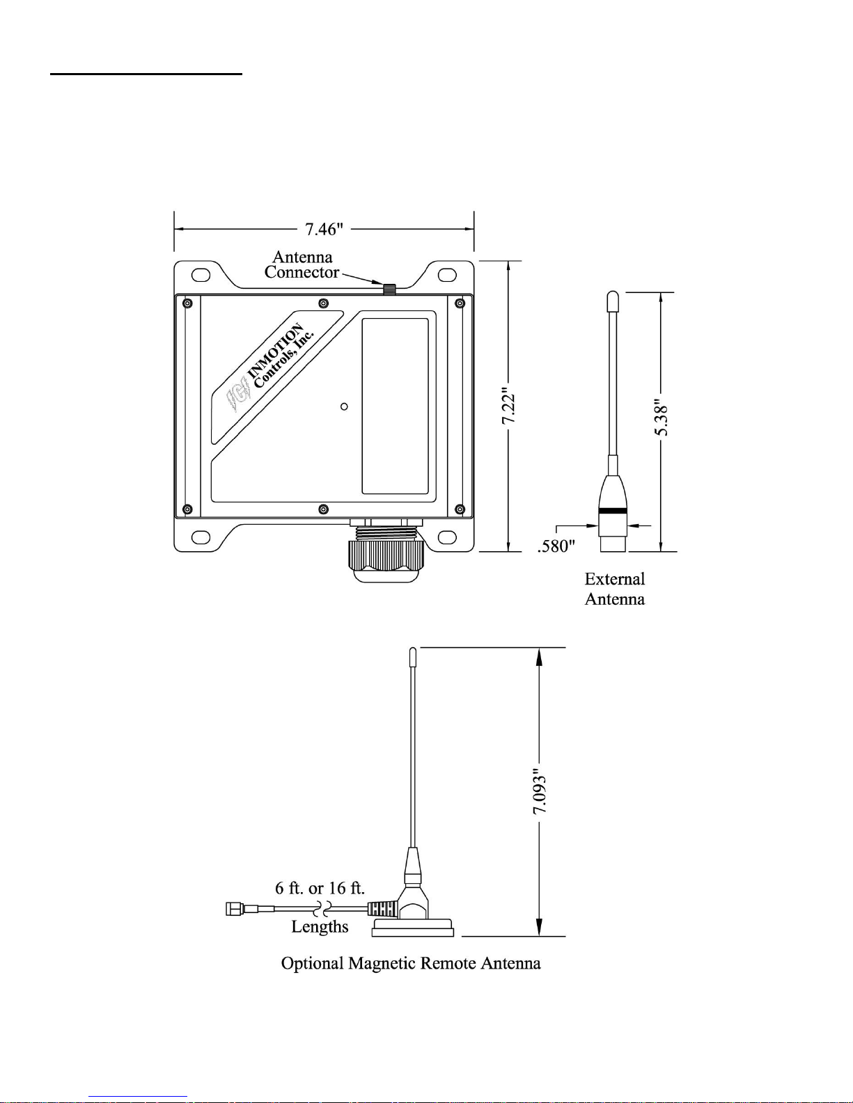
Chapter 3: Receiver
Receiver Dimensions (Not to scale)
Page 11

11
Chapter 4: Troubleshooting
Page 12

12
Chapter 5: Accessories
Pushbutton Protector
Waterproof Case
Lanyard
 Loading...