

Inmarsat Terra 400 Quick Start Manual
Terra 400 & Oceana 400
Quick Start Guide
www.beamcommunications.com
PART #: USRQSG006801
BEAM Communications Pty Ltd
8 Anzed Court, Mulgrave
Victoria, 3170, AUSTRALIA
Web: www.beamcommunications.com
Information: info@beamcommunications.com
Support: support@beamcommunications.com
Tel: +61 3 8588 4500
Fax: +61 3 9560 9055
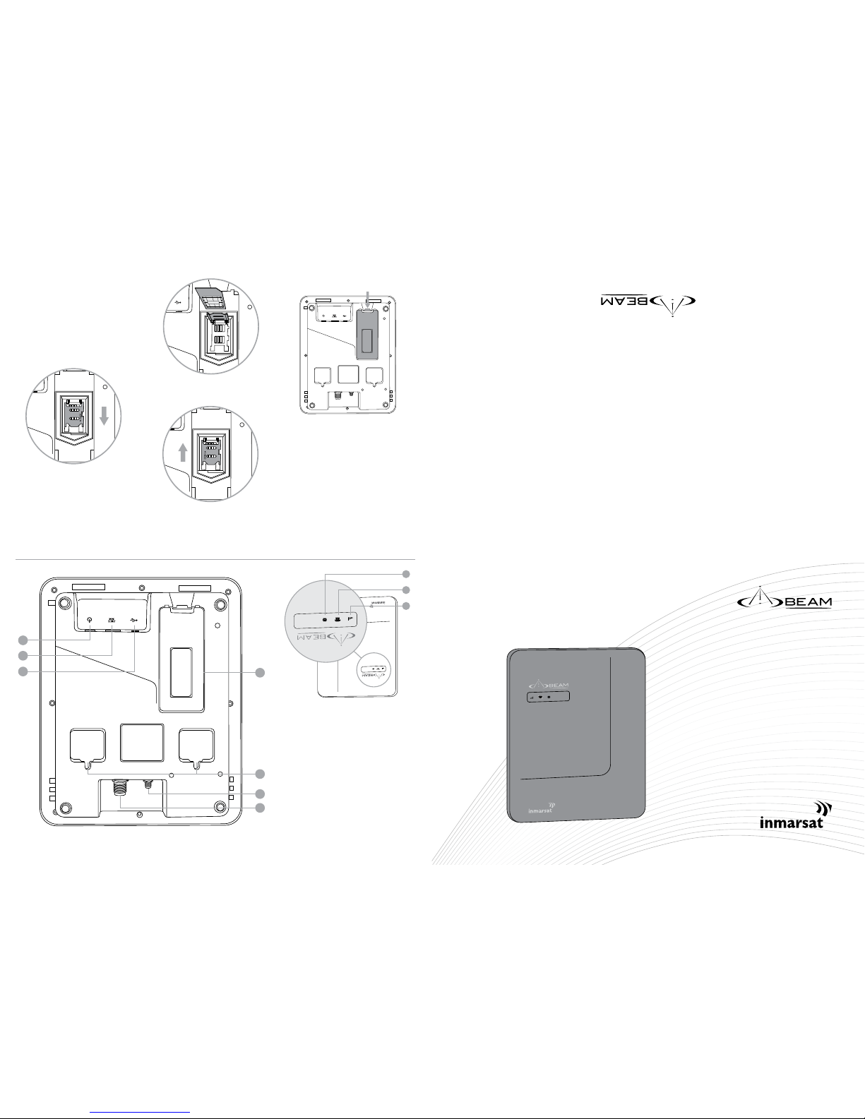
2. SIM Instrallation
If your Service Provider has not installed
the SIM card for you, follow these steps
to install.
1. Turn power OFF to the Terminal.
Failure to turn OFF can result
in corruption of your SIM card
memory.
2. Release the SIM cover by
unclipping the latch with your
nger or thumb. The SIM Cover is
shown highlighted below.
3. Slide the tray guide of the SIM
connector into the Open position.
4. Raise the SIM tray as shown below.
5. Gently insert the SIM card into
the tray slots making sure that
the golden connectors are facing
downwards.
6. Lower the tray and slide the tray
guide into the lock position.
7. Replace the SIM cover.
1. Terra 400 & Oceana 400 Equipment
Overview
1. Signal LED
2. Call LED
3. Message LED
4. Antenna TNC Connector
5. GPS SMA Connector
6. Wall Moutning Hooks
7. SIM Card Slot and Cover
8. USB Port
9. POTS/RJ11 Port
10. Power Port
Terra 400
Terra 400
1
5
4
2
6
3
7
8
9
10
Terra 400
4. Connecting Power to the Terminal
The TR400/OC400 terminal can be
powered from the supplied AC Plug pack,
or connected to an external 10-32V DC
power source.
ISD950 AC Plug Pack Installati on
For installation using the ISD950 110240 AC plug pack, connect the 4-way
Microt connector from the plug pack
to the 4-way power connector on the
rear of the TR400/OC400 terminal. In this
conguration the status is always ON.
DC Power Source Inst allation
The RED and BLACK wires are used for the
power connection, The YELLOW wire can
be connected to a circuit to sync the ON/
OFF status of the TR400/OC400 terminal
with a vessels/in-building operation.
By default, the TR400/OC400 terminal
will stay on for 20 minutes after this
input (YELLOW wire) is switched OFF. If
a call is in progress while this occurs, the
TR400/OC400 terminal will stay on for 20
minutes after the call is terminated.
1. Route the wire end of the DC power
cable to the connection point.
2. Connect the BLACK wire to the negative
terminal of the battery or the vessel
chassis (if negatively grounded chassis).
3. Connect the RED wire to the
positive terminal of the battery. It is
recommended to add the 5A fuse
(supplied) between them.
4. Connect the YELLOW wire to the
vessel accessory power or ON/OFF
Switch wire. If the accessory power is
unavailable, this may be connected
to a vessel ignition voltage. It is
recommended to add a 1A fuse
between them. The accessory wire
enables the TR400/OC400 to turn on
and o. If this function is not required,
the YELLOW wire MUST be connected
to the RED wire.
5. Connect the 4-way Microt connector
on the DC power cable to the 4-way
power connector on the rear of the
TR400/OC400.
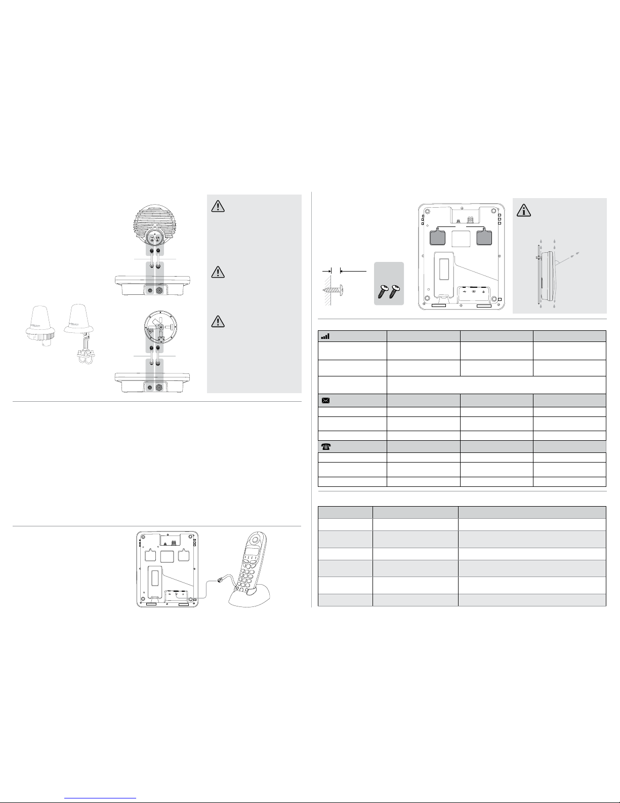
6. Wall Mounting & Locking Bolt
There are two mounting points at the back
of the terminal (as shown, shaded, in the
below image). The distance (from centre to
centre) between the mounting points is 10
cm. To mount the terminal vertically on a
wall, sit the two included screws with 4mm
remaning out of the wall. Adjust this depth
till the terminal hangs securly on the screws.
NOTE
Vertical (wall) mounting orientation is required to
maintain IP53 rain protection.
8. Terra 400 / Oceana 400 Types of Tones
7. Terra 400 / Oceana 400 Status Table
3. Antenna Connection
1. Refer to the antennas installation
guide for antenna mounting and
location requirements.
2. Connect the antenna cable labelled
“GPS” to the SMA antenna connector
labelled “GPS”.
3. Connect the antenna cable labelled
“Inmarsat” to the SMA antenna connector
labelled “ISAT”.
4. Connect the GPS-SMA (F) cable end to
the IsatDock’s SMA connector
5. Connect the TNC (F) antenna cable
end to the IsatDock’s satellite
connector.
ISD710 - FOR USE WITH OC400
ISD700 - FOR USE WITH TR400
WARNING
DO NOT pull with force on the cables from the
rear of the OC400/TR400. Please install strain relief
clamping for the antenna cables where required.
Correct installation of the antenna system is a
vital part of theOC400/TR400 system, to ensure
reliable functionality, and drop-free calls.
WARNING
Changes or modications not expressly approved
by Beam Communications could void the
Terminals warranty.
WARNING
To satisfy FCC RF exposure requirements for mobile
transmitting devices, a separation distance of
55cm or more should be maintained between the
antenna of this device and persons during device
operation. To ensure compliance, operations at
closer than this distance is not recommended.
5.Connect POTS/RJ11
Any stan dard analog ue POTS tele phone
(POTS = P lain Old T elephone S ervice)
is supp orted by t he TR400/OC40 0
Terminal. Th e Terminal suppl ies power
to the analogue ph one as well as ring,
dial an d busy tone s.
The analogue phone can be connected
by up to 600m (2000’) of cabling to the
TR400/OC400.
54
3
2
TNC
SMA
SMA
SMA
Satellite
Antenna
Cable
GPS
Antenna
Cable
THIS SIDE UP
54
3
2
TNC
SMA
SMA
SMA
Satellite
Antenna
Cable
GPS
Antenna
Cable
ISD710
Maritime Antenna
(Active)
For use with OC400
ISD700
Fixed/Directional
Antenna (Passive)
For use with
TR400
10cm
MOUTING
SCREWS
~4mm
<60°
TYPE OF TONE SOUND DESCRIPTION
Dial Tone Continuous tone Telephone ready for use
Progress Tone Continuous short beep, with 3
second interval
Number has been dialled but call has yet to connect.
Unavailable Tone Beeping tone (engaged) Phone is not registered, or no signal. Calls cannot be made
SIM PIN Required Alternating low and lower tones (1
sec intervals)
A SIM PIN is required to be entered
SIM PUK Required Alternating low and lower tones (2
sec intervals)
A PUK code is required to be entered
Phone o-hook Fast ascending tone, repeating. Phone has been left ohook for > 15 seconds and is not in a call.
SIGNAL LED
GREEN RED YELLOW
ON Good signal
Registered
No signal
Registered
Poor signal
Registered
FLASHING Good signal
Not registered
No Signal
Not registered
Poor signal
Not registered
ALTERNATING Alternating GREEN, YELLOW, RED.
Error state entered. The Call and Message LED’s indicate the error code.
MESSAGE LED
GREEN RED YELLOW
ON
N/A N/A N/A
FLASHING
Voice mail has been received SMS is present in the inbox Both a voice mail and inbound
SMS has been received
ALTERNATING
N/A N/A N/A
CALL LED
GREEN RED YELLOW
ON
POTS o-hook N/A DTR present on data port
FLASHING
POTS call in progress N/A Data call in progress (DCD
active)
ALTERNATING
N/A N/A N/A
 Loading...