


A Mobile Satcom Product of GLOCOM, INC.
GX-9
Inmarsat Fleet Broadband 250
Maritime User Terminal
Operating Manual
Version 1.0
GLOCOM
Glocom GX-9 (FB250 Class) Operating Manual
The information contained within this document is the sole property of GLOCOM, INC. No part of
this publication may be reproduced or transcribed without written permission from GLOCOM. All
rights reserved.
For your safety and protection, read this entire user manual before you attempt to use the Fleet
Broadband Marine Satellite Terminal. In particular, read this safety section carefully. Keep this safety
information where you can refer to it if necessary.
SSSSAFETY
AFETY I
AFETY AFETY
INFORMATION
NFORMATION
II
NFORMATIONNFORMATION
WARNING SYMBOLS USED IN THIS MANUAL
WARNING
Potential radio Frequency (RF) hazard. Where you see this alert symbol and
WARNING heading, strictly follow the warning instructions to avoid injury to eyes or
other personal injury.
WARNING
Where you see this alert symbol and WARNING heading, strictly follow the warning
instructions to avoid personal injury.
DANGER
Electric shock hazard: Where you see this alert symbol and DANGER heading, strictly
follow the warning instructions to avoid electric shock injury or death.
WARNINGS FOR SATELLITE TERMINAL
DO NOT STAND IN FRONT OF THE ANTENNA
This device emits radio frequency energy. To avoid injury, do not place head or other
body parts in front of the satellite antenna when system is operational. Maintain a
distance of two meters or more from the front of the Satellite Terminal antenna.
PROPERLY GROUND THE EXTERNAL ANTENNA
Failure to properly ground the optional external antenna may result in severe personal
injury or death. Do not attempt to ground the optional external antenna unless you
have the skills to do so in accordance with local electrical codes.
DO NOT OPERATE DURING ELECTRICAL STORMS
Operation of the Satellite Terminal during electrical storms may result in severe
personal injury or death. Disconnect the Terminal from the computer and store the unit
indoors if lightning is anticipated in the area of operation.
ii Glocom GX-9 Operating Manual
GGGGENERAL
ENERAL
ENERALENERAL
Handle your Satellite Terminal with care. The enclosure is weather resistant per IEC
60529 IP54; however, do not submerge the unit or expose it to severe rain storms.
Avoid exposing your Satellite Terminal to extreme hot or cold temperatures outside the
range -25ºC to +60ºC.
Avoid placing the Terminal close to cigarettes, open flames or any source of heat.
Changes or modifications to the Terminal not expressly approved by Glocom Inc.,
could void your authority to operate this equipment.
Only use a soft damp cloth to clean the Terminal.
To avoid impaired Terminal performance, please ensure the unit’s antenna is not
damaged or covered with foreign material like paint or labeling.
When inserting the USIM/SIM, do not bend it or damage the contacts in any way.
When connecting the interface cables, do not use excessive force.
IIIIN THE VICINITY OF BL
N THE VICINITY OF BLASTING WORK AND IN E
N THE VICINITY OF BLN THE VICINITY OF BL
Never use the Satellite Terminal where blasting work is in progress. Observe all
restrictions and follow any regulations or rules. Areas with a potentially explosive
environment are often, but not always, clearly marked. Do not use the Terminal while
at a petrol filling station. Do not use near fuel or chemicals.
QQQQUA
UALIFIED
LIFIED S
UAUA
LIFIED LIFIED
Do not attempt to disassemble your Satellite Terminal. The unit does not contain
consumer-serviceable components. Only qualified service personnel may install or
repair equipment.
AAAACCESSORIES
CCESSORIES
CCESSORIESCCESSORIES
Use Glocom approved accessories only. Use of non-approved accessories may result
in loss of performance, damage to the Satellite Terminal, fire, electric shock or injury.
SERVICE
ERVICE
SS
ERVICEERVICE
ASTING WORK AND IN EXPLOSIVE ENVIRONMENT
ASTING WORK AND IN EASTING WORK AND IN E
XPLOSIVE ENVIRONMENTSSSS
XPLOSIVE ENVIRONMENTXPLOSIVE ENVIRONMENT
CCCCONNECTING
ONNECTING D
ONNECTING ONNECTING
Never connect incompatible devices to the Satellite Terminal. When connecting the
Satellite Terminal to any other device, read the device’s User Manual for detailed
safety instructions.
Glocom GX-9 (FB250 Class) Operating Manual
DEVICES
DD
EVICES
EVICESEVICES

PPPPACEMAKERS
ACEMAKERS
ACEMAKERSACEMAKERS
The various brands and models of cardiac pacemakers available exhibit a wide range
of immunity levels to radio signals. Therefore, people who wear a cardiac pacemaker
and who want to use a Satellite Terminal should seek the advice of their cardiologist.
If, as a pacemaker user, you are still concerned about interaction with the Satellite
Terminal, we suggest you follow these guidelines:
Maintain a distance of 30 cm between the Terminal and your pacemaker;
Maintain a distance of two meters from the front of the unit’s antenna;
Refer to your pacemaker product literature for information on your particular device.
If you have any reason to suspect that interference is taking place, turn off your
Satellite Terminal immediately!
HHHHEARING
EARING A
EARING EARING
Most new models of hearing aids are immune to radio frequency interference from
Satellite Terminals that are more than 2 meters away. Many types of older hearing
AIDS
IDS
AA
IDSIDS
aids may be susceptible to interference, making it very difficult to use them near a
Terminal. Should interference be experienced, maintain additional separation between
you and the Satellite Terminal.
iv Glocom GX-9 Operating Manual

CCCCONTENTS
ONTENTS
ONTENTSONTENTS
GX-9 ________________________________________________________ I
SAFETY INFORMATION _________________________________________ II
Warning Symbols Used in this Manual............................................................................ii
Warnings for Satellite Terminal ........................................................................................ii
CONTENTS___________________________________________________ V
INTRODUCTION _______________________________________________ 1
About This Product..............................................................................................................1
About This Operating Manual ...........................................................................................1
Package Contents..................................................................................................................1
Minimum System Requirements for Laptop/PC............................................................2
GETTING STARTED ____________________________________________ 3
Introduction to Getting Started........................................................................................3
Setting Up Your Terminal...................................................................................................3
USING THE GX-9 _____________________________________________ 4
Auto Start configuration......................................................................................................4
Power Up and Connection to the Internet....................................................................4
Connecting the Terminal to the Computer...................................................................4
Connecting by USB......................................................................................................6
TTTTO CONNECT THE
O CONNECT THE GX
O CONNECT THE O CONNECT THE
Connecting by Ethernet..............................................................................................6
TTTTO CONNECT THE
O CONNECT THE GX
O CONNECT THE O CONNECT THE
Connecting by WLAN.................................................................................................6
Connecting the Analog Phone/Fax Machine...................................................................6
Dialing from TEL1 or TEL2........................................................................................7
Connecting the ISDN Device ............................................................................................7
Coverage Map........................................................................................................................8
GX----9999 TO THE COMPUTER USI
TO THE COMPUTER USING THE
GXGX
TO THE COMPUTER USI TO THE COMPUTER USI
GX----9999 TO THE COMPUTER USI
TO THE COMPUTER USING
GXGX
TO THE COMPUTER USI TO THE COMPUTER USI
NG THE USB
NG THE NG THE
NG E
NG NG
USB PORT
USBUSB
ETHERNET
THERNET:
EE
THERNETTHERNET
PORT:
: ______ 6
PORT PORT
::
: __________ 6
::
USING THE GLOCOM WEB MMI _________________________________ 9
Accessing the UT Web MMI..............................................................................................9
Properties Page...................................................................................................................10
Setup Page............................................................................................................................12
Statistics................................................................................................................................ 14
PDP Contexts.....................................................................................................................15
AAAACTIVATING A
CTIVATING A PDP
CTIVATING A CTIVATING A
Glocom GX-9 (FB250 Class) Operating Manual
PDP
PDPPDP
C
CONTEXT
CC
ONTEXT:
ONTEXTONTEXT
: ___________________________________ 16
::

BBBBACKGROUND
ACKGROUND C
ACKGROUND ACKGROUND
CID
CID
#1
#1
I
INACTIVE
CIDCID
AAAACTIVATING
CTIVATING M
CTIVATING CTIVATING
ACA
ACA SETTINGS FOR
ACAACA
EEEELEVATION
LEVATION:
LEVATIONLEVATION
NACTIVE;
#1#1
II
NACTIVENACTIVE
WLAN ..................................................................................................................................19
Connecting by WLAN.............................................................................................. 19
WEP Security ...................................................................................................................... 20
ACA.......................................................................................................................................22
SETTINGS FOR TE
SETTINGS FOR SETTINGS FOR
ISDN......................................................................................................................................26
Antenna ................................................................................................................................28
TROUBLE SHOOTING _________________________________________ 30
CONTEXT ACTIVATED FOR
ONTEXT ACTIVATED FOR 192.168.128.101
CC
ONTEXT ACTIVATED FORONTEXT ACTIVATED FOR
;
CID
CID
#2
#2
&
&
3
3 ACTIVE
;;
CIDCID
#2#2
MULTIPLE
ULTIPLE PDP
MM
ULTIPLE ULTIPLE
:
THE CURRENT ELEVATIO
THE CURRENT ELEVATION ANGLE OF THE ANTEN
::
THE CURRENT ELEVATIOTHE CURRENT ELEVATIO
PDP
PDPPDP
TES WITH
S WITH S
TETE
S WITH S WITH
ACTIVE _____________________________ 17
&&
33
ACTIVE ACTIVE
C
CONTEXTS
ONTEXTS ___________________________ 18
CC
ONTEXTSONTEXTS
STATIC
TATIC IP
SS
TATIC TATIC
192.168.128.101 ___________ 16
192.168.128.101192.168.128.101
IP ADDRESS
ADDRESS:
IPIP
ADDRESS ADDRESS
N ANGLE OF THE ANTENNA
N ANGLE OF THE ANTENN ANGLE OF THE ANTEN
: _________________ 22
::
NA_________ 28
NANA
TECHNOLOGY OVERVIEW _____________________________________ 33
GPS ........................................................................................................................................33
Obtaining a GPS Fix.................................................................................................. 33
GPS and BGAN Registration..................................................................................33
ISDN......................................................................................................................................35
Dialing and Numbering.............................................................................................35
PDP Context.......................................................................................................................35
WLAN ..................................................................................................................................37
Performance................................................................................................................37
SSID...............................................................................................................................37
TECHNICAL SPECIFICATIONS___________________________________ 38
DECLARATION OF CONFORMITY ________________________________ 39
PHOENIX
PHOENIX
PHOENIXPHOENIX
TESTLAB
TESTLAB
TESTLABTESTLAB
G
GMB
MBH,
GG
MBMB
H,
K
Kӧ
ӧNIGSWINKEL
NIGSWINKEL 10,
H,H,
KK
ӧӧ
NIGSWINKEL NIGSWINKEL
10,
10,10,
D
-32825
32825
DDD---
3282532825
B
BLOMBERG
LOMBERG,
BB
LOMBERGLOMBERG
,
G
GERMANY
ERMANY.
,,
GG
ERMANYERMANY
____________________________________________________________ 39
GLOCOM INC., 22 FIRSTFIELD RD., STE 125 GAITHERSBURG, MD 20878 USA
____________________________________________________________ 39
FCC Compliance................................................................................................................ 39
.
..
EU WEEE (Waste Electrical and Electronic Equipment) Directives..................... 40
GLOSSARY __________________________________________________ 41
UT (USER TERMINAL): THE USER TERMINAL IS THE BGAN MODEM DEVICE42
vi Glocom GX-9 Operating Manual

a b
c d e
f
g
IIIINTRODUCTION
NTRODUCTION
NTRODUCTIONNTRODUCTION
ABOUT THIS PRODUCT
The Glocom GX-9 (an Inmarsat FB250 class) Satellite Terminal provides a comprehensive range of
voice and data services using the Inmarsat Broadband Global Area Network (BGAN) satellites. These
services support a wide range of applications including placing and receiving telephone calls, WEB
browsing, email, and other Internet data services. Data services can be accessed using either Ethernet
LAN, built in wireless WiFi Access Point, USB or ISDN connections. Voice services can be accessed
through a standard RJ-11 interface or by ISDN. The GX-9 allows simultaneous voice service while
browsing the WEB, sending and receiving email, or using other data services.
The GX-9 consists of a compact antenna Above Deck Unit (ADU) and a modem and interface Below
Decks Unit (BDU) that are connected by a single cable. The antenna includes a 3-axis stabilized design
that automatically acquires and tracks the satellite while the vessel is underway over a wide range of
vessel motion and sea conditions. The BDU can be conveniently located anywhere on the vessel. It
provides interfaces for standard telephones (RJ-11), Ethernet WAN (RJ-45), USB, ISDN and wireless
WiFi connections to multiple PCs, PDAs, or other Terminal Equipments (TE). The GX-9’s operates on a
wide range of input voltage from 10.8 to 31.2 Vdc. Detailed specification are listed on page 38.
ABOUT THIS OPERATING MANUAL
This document contains the information require to operate the GX-9 Fleet Broadband Satellite Terminal
including procedures for start up, registering on the network and using the various voice and data
services available.
PACKAGE CONTENTS
The GX-9 Standard package includes the following items:
a. Above Deck Unit (ADU) x1
b. Below Deck Unit (BDU) x1
c. ADU/BDU Coaxial Cable (LMR-300 15m)
d. Flexible pigtail coaxial cable (RG223 1ft)
e. DC-DC Power Cable (5m) x1
f. Operating Manual on CD x1
g. GX-9 15A spare fuse x2
Glocom GX-9 (FB250 Class) Operating Manual 1

The following optional items are available:
Extended ADUE/BDU LMR-600 Coaxial Cable, 50m
ADU Mast Pole Mounting Kit
A Subscriber Identification Module (SIM) and its PIN which are needed to access the Inmarsat network
can be provided by your Inmarsat Service provider along with related configuration instructions for the
Satellite Terminal.
Note: The SIM card will also have four (4) MSISDN numbers associated with it for the ISDN services:
4K Voice
3.1KHz Audio/Fax
64K UDI data
56K RDI data
MINIMUM SYSTEM REQUIREMENTS FOR LAPTOP/PC
These are the minimum computer system requirements for successful interface with the Satellite
Terminal:
CD-ROM (for installation CD)
Internet Browser: Microsoft Internet Explorer version 5.5 or later; Netscape Communicator version 7.0 or
later (Java must be active).
PC Support for at least one of these interfaces – Ethernet, ISDN or WLAN (802.11b or b/g).
Intel Pentium III CPU, or equivalent.
100 MB of free hard disk space.
128 MB of RAM.
2 Glocom GX-9 (FB250) Operating Manual

GGGGETTING
ETTING S
ETTING ETTING
INTRODUCTION TO GETTING STARTED
This guide outlines the procedure to connect to the Inmarsat network. It will guided you through the
procedure for powering up your terminal, obtaining a GPS position fix, connecting your computer to the
terminal and registering with the BGAN network. You are then ready to start using voice and broadband
services.
SETTING UP YOUR TERMINAL
Set up the GX-9 terminal as follows.
1. Verify that the ADU and BDU are
STARTED
TARTED
SS
TARTEDTARTED
properly connected by the coaxial
cable. And the BDU is connected to a
suitable source of dc power. Refer to
the GX-9 Installation Instructions for
details.
2. Press the power ON/OFF switch
(located at the left corner of the BDU
front panel). The power LED will
illuminate. The flashing READY LED
indicates that the antenna is
automatically scanning the sky, the
GPS receiver is acquiring a position
fix, and the software is preparing the
terminal for operation. When the
satellite signal has been acquired the
READY LED will change from flashing
to steady on. The terminal is now
ready to operate.
Glocom GX-9 (FB250 Class) Operating Manual 3

UUUUSING THE
SING THE GX
SING THE SING THE
AUTO START CONFIGURATION
The terminal is configured by default to automatically attempt to register with the Inmarsat network once
the antenna has acquired the satellite signal and obtained a GPS position fix.
GX----9999
GXGX
Note
These default configurations are accessible through LaunchPad or the web Man-Machine
Interface (MMI). It is recommended that these settings be retained for convenient operation
of the GX-9 Terminal.
POWER UP AND CONNECTION TO THE INTERNET
When power is first applied GX-9 will begin a start-up sequence. The antenna will begin its search for the
satellite and the antenna motors may be heard during this time. Note that the antenna must have line of
sight view towards the satellite.
When the vessel is at a fixed location after acquiring the satellite signal the antenna will continue to make
minor adjustments to optimize the signal strength. During this time the you may hear the antenna motors
“tweaking” its direction toward the satellite. If the vessel is completely stationary the antenna will find an
optimum position and stop searching.
When the vessel is underway the antenna will automatically track the satellite signal and keep the
antenna pointed towards the satellite. During short outages (caused by moving under a bridge) the
antenna will remain in the same position and will re-acquire the satellite signal immediately after the
blockage is removed. For longer outages the antenna may need to repeat the search sequence to
reacquire the satellite signal.
Note
Circuit switched and packet switched connections will recover from signal outages of less
than 60 seconds. User intervention may be required to reactivate connections for outage
longer than 60 seconds.
CONNECTING THE TERMINAL TO THE COMPUTER
You can connect your computer to the GX-9 with one or more of the following interfaces
USB
Ethernet
WLAN
4 Glocom GX-9 (FB250) Operating Manual

Note
Note
There is no need to check the active interface. All interfaces can be used
simultaneously to accommodate multiple users.
During initial setup, the terminal can only be configured using either a USB or an
Ethernet connection. Once the terminal has been configured, all five interfaces (USB,
RJ-11, Ethernet, WLAN and ISDN) can be used for data transfer depending on the
service required.
Your computer must be configured to support your chosen connection method. Refer to
the documentation supplied with your computer for details.
Glocom GX-9 (FB250 Class) Operating Manual 5

CCCCONNECTING BY
ONNECTING BY USB
ONNECTING BY ONNECTING BY
To connect the
To connect the GX
To connect the To connect the
1. Connect a USB cable between your computer’s USB port and the GX-9’s USB port.
USB
USBUSB
GX----9999 to the computer using the USB port:
to the computer using the USB port:
GXGX
to the computer using the USB port: to the computer using the USB port:
Note
If you install LaunchPad software on your PC, the USB driver for the GX-9 will also be installed.
When you plug the USB cable into your computer for the first time, your computer will detect that a
new USB device has been connected. Follow the computer’s instruction to install the Glocom USB
LAN LINK
LAN LINK driver software (for computers using the Windows operating system, the installation is
LAN LINKLAN LINK
carried out using a Found New Hardware Wizard
to the GX-9.
If you do not install LaunchPad, USB drivers are available from: www.inmarsat.com/support or
www.glocom-us.com
CCCCONNECTING BY
ONNECTING BY E
ONNECTING BY ONNECTING BY
To connect the
To connect the GX
To connect the To connect the
When plugging in the USB cable for the first time, you will see Windows installing a new
driver for the device.
Glocom USB
Glocom USB Glocom USB
Found New Hardware Wizard). Your computer will then use this driver to connect
Found New Hardware WizardFound New Hardware Wizard
ETHERNET
THERNET
EE
THERNETTHERNET
GX----9999 to the computer using Ethernet:
to the computer using Ethernet:
GXGX
to the computer using Ethernet: to the computer using Ethernet:
1. Connect an Ethernet cable between your computer’s Ethernet port and the GX-9’s Ethernet port.
CCCCONNECTING BY
ONNECTING BY WLAN
ONNECTING BYONNECTING BY
If you have not previously used the GX-9’s WLAN interface, it must first be enabled using either the GX-
9’s internal web Man-Machine Interface (MMI) or LaunchPad while your computer is connected to the GX-
9 using either the USB or Ethernet interface.
When you are configuring the WLAN, you can also enable the Wireless Encryption Protocol (WEP), MAC
address filtering, and no broadcast SSID features for added security.
Once the WLAN is appropriately configured and turned ON any device with a WLAN interface can detect
the GX-9’s WLAN SSID, and connect to it automatically.
Note: If WEP is enabled, you must provide WLAN users with the proper WEP key in order for them to
connect to the GX-9.
WLAN
WLANWLAN
CONNECTING THE ANALOG PHONE/FAX MACHINE
6 Glocom GX-9 (FB250) Operating Manual

BGAN provides circuit switched fax service via an ISDN 3.1KHz audio channel. You may connect your
analog fax machine to either an ISDN terminal adaptor which is connected to the GX-9 ISDN port or
directly to the TEL1 (RJ-11) port. Even though it is more convenient to connect an analog fax to a RJ-11
port be aware that the BGAN fax calls are charged at ISDN rate (usually higher than the BGAN low rate
voice service).
A voice call made via TEL1 will be charged as an ISDN 3.1kHz audio service – if user did not
used the forced service dialing sequence (see below).
DDDDIALING FROM
IALING FROM TEL1
IALING FROM IALING FROM
1. Dial-up without forced service type
Port Service Type
TEL1 3.1kHz Audio (FAX)
TEL1 OR
OR TEL2
OR OR
TEL2
TEL2TEL2
TEL1TEL1
• Regular Dialing
• Redialing
TEL2 4kbps AMBE
2. Dial-up with forced service type
• Regular Dialing - 4kbps AMBE
• Redialing - 4kbps AMBE
• Regular Dialing – 3.1kHz Audio
• Redialing – 3.1kHz Audio
CONNECTING THE ISDN DEVICE
You can connect an ISDN device (e.g. ISDN phone, ISDN TA etc) to the ISDN port on GX-9 terminal to access
circuit-switched service.
Dial-up from ISDN port:
Glocom GX-9 (FB250 Class) Operating Manual 7

COVERAGE MAP
The GX-9 will perform best in areas where the elevation angle is 20 degrees or higher. Lower elevation
angles increase the probability of signal outages caused by the vessel rolling and pitching and may
severely impact the usability while underway in heavy seas.
8 Glocom GX-9 (FB250) Operating Manual
UUUUSING THE
SING THE G
ACCESSING THE UT WEB MMI
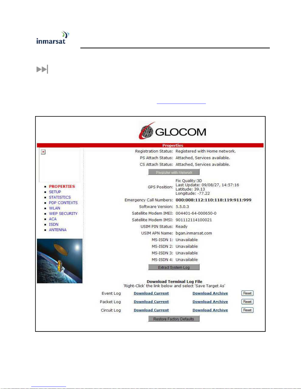
The GX-9 includes an internal Web MMI. To access the UT Web MMI, open your preferred Web
Browser and enter the internal IP address of the GX-9, http://192.168.128.100. The web MMI opens to
the “Properties” page as shown below:
SING THE SING THE
GLOCOM
LOCOM W
GG
LOCOM LOCOM
WEB
EB MMI
WW
EB EB
MMI
MMIMMI
Glocom GX-9 (FB250 Class) Operating Manual 9

PROPERTIES PAGE
The Properties page shows the current status of the GX-9. A description of each item on the page
follows:
In the Top left-hand corner of the screen you will notice that there are three status items: Satellite Signal
Strength, Beam ID, and input power status. These items are updated automatically when their status
changes.
Network Status:
Network Status: This shows the current status of the network, two messages appear in this field:
Network Status:Network Status:
1. Registration Status: This field indicates whether the GX-9 is Registered with the Network. Click
on the “Register with Network” button. Note:
that the GX-9 will automatically register with the Network each time.
Note: Bypass antenna pointing is turned on as default so
Note:Note:
10 Glocom GX-9 (FB250) Operating Manual

2. PS Attach Status
PS Attach Status: This indicates whether the GX-9 is PS (Packet Switch) attached to the
PS Attach StatusPS Attach Status
Network. You will need to setup a PDP context in order to send PS data.
3. CS Attached
CS Attached: This indicates whether the GX-9 is CS (Circuit Switch) attached to the Network.
CS AttachedCS Attached
Once you are CS Attached and Registered with the network, you are able to make CS calls.
4. GPS Position:
GPS Position: This field displays the current GPS position status. If the GX-9 has received a
GPS Position:GPS Position:
GPS position fix and the Network GPS policy has been received then the GPS Fix Quality, Last
Update time and the Position (Latitude, Longitude) will be displayed. Time is GMT.
5. Emergency Call Numbers:
Emergency Call Numbers: This field displays the Emergency call numbers that can be used with
Emergency Call Numbers:Emergency Call Numbers:
the GX-9.
6. Software
Software Version:
SoftwareSoftware
7. Satellite Modem IMEI:
Satellite Modem IMEI: This displays the IMEI number of the GX-9.
Satellite Modem IMEI:Satellite Modem IMEI:
8. Satellite Modem IMSI
Satellite Modem IMSI: This displays the IMSI number of the USIM card in the GX-9. If is the IMSI
Satellite Modem IMSISatellite Modem IMSI
is not displayed, it indicates that there is a problem reading the SIM card, e.g. because there is no
SIM, it is installed incorrectly or PIN must be entered.
Version: This displays the current version of software that is running on the GX-9.
Version: Version:
9. USIM PIN Status
USIM PIN Status: This field indicates whether the USIM is ready or a PIN needs to be entered. If
USIM PIN StatusUSIM PIN Status
the PIN needs to be entered, go to the SETUP page.
10. USIM APN Name:
USIM APN Name: This displays the default APN that has been provisioned on the USIM card.
USIM APN Name:USIM APN Name:
Note that some USIM cards may have multiple APN’s provisioned on them.
11. MS
MS----ISDN 1 thru 4:
ISDN 1 thru 4: Each USIM card has four (4) separate MS-ISDN numbers if the USIM has
MSMS
ISDN 1 thru 4: ISDN 1 thru 4:
been provisioned for these services. MS_ISDN 1 is for 4K Speech, MS-ISDN 2 is for 3.1KHz
Audio (fax, etc.), MS-ISDN 3 is for UDI data, and MS-ISDN 4 is for RDI data.
12. Extract System Log:
Extract System Log: Clicking this button allows the User to automatically extract a GX-9 system
Extract System Log: Extract System Log:
log and save the file to a location on the PC for debugging purposes. This file can be e-mailed to
Glocom directly for fault analysis if the User experiences any problems.
13. Restore factory Defaults:
Restore factory Defaults: Clicking this button will restore the GX-9 back to factory defaults and
Restore factory Defaults:Restore factory Defaults:
delete any of the user parameters that have been entered in the GX-9. It is recommended that
the user exhaust all possible debug procedures before using this feature.
Glocom GX-9 (FB250 Class) Operating Manual 11
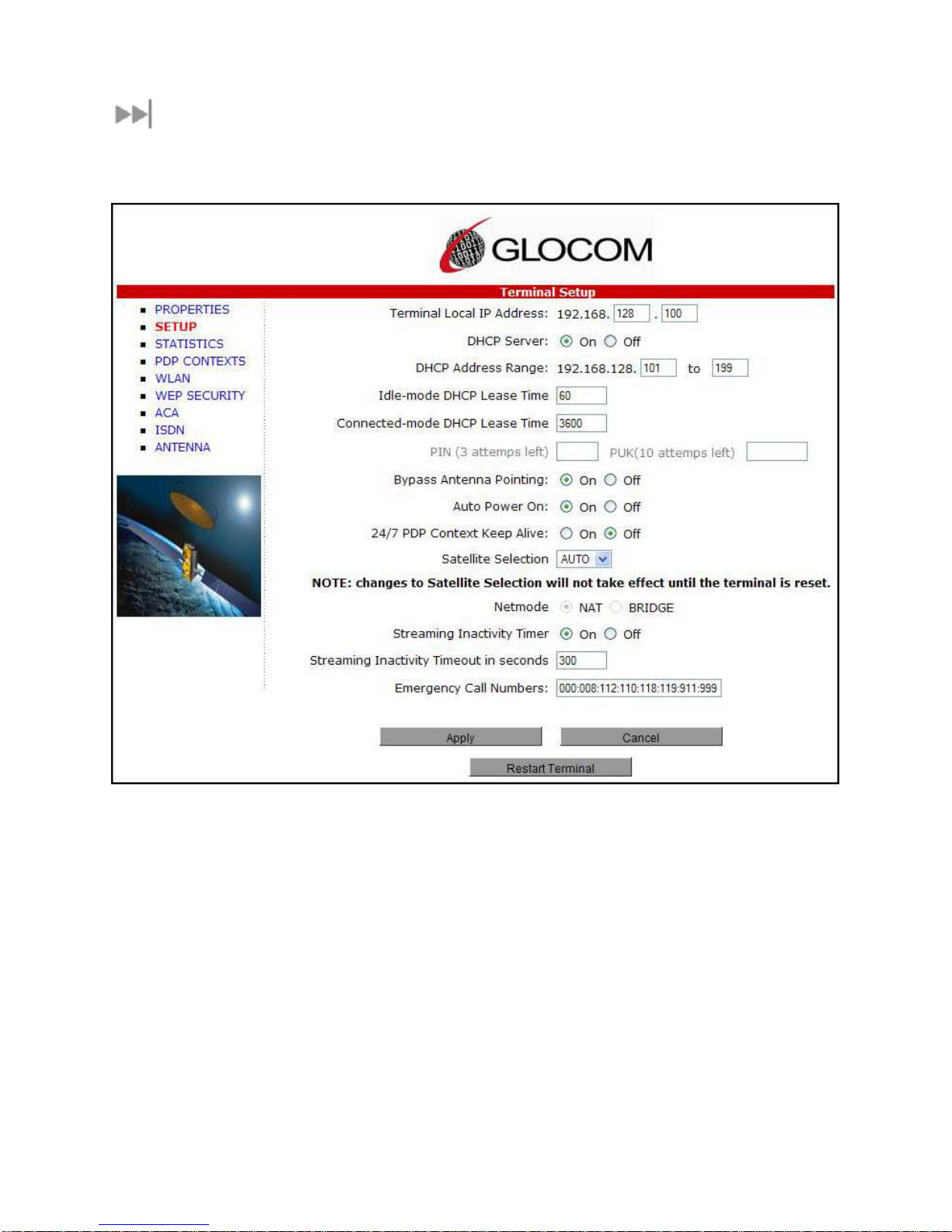
SETUP PAGE
The Setup page allows the user to configure various parameters of the GX-9. A description of each item
on the screen follows:
1. Terminal Local IP Address
Terminal Local IP Address: This allows the User to change the local IP address of the terminal
Terminal Local IP AddressTerminal Local IP Address
from the default 192.168.128.100 IP address. Only the last two octets are available to change.
Once the local IP address is changed on this page and applied, the IP address ranges for the
DHCP server, the PDP Context page and ACA page will also be changed automatically. Note:
Updates to this field will not take affect until the GX-9 is rebooted.
2. DHCP Address Range:
DHCP Address Range: This allows the User to set the range of DHCP addresses that are given
DHCP Address Range: DHCP Address Range:
out by the GX-9 to any connected PC or other Terminal Equipment (TE).
3. Idle
Idle----mode DHCP Lease Time:
mode DHCP Lease Time: Idle-mode DHCP Lease Time refers to the DHCP lease time
IdleIdle
mode DHCP Lease Time: mode DHCP Lease Time:
when the UT is not connected to the network. This parameter allows the User to change the
duration (default is 60 seconds) of the DHCP lease. This parameter was introduced to address a
situation with some models of Cisco routers that will not accept a short DHCP lease time. Note:
12 Glocom GX-9 (FB250) Operating Manual
Note:
Note: Note:
Note:
Note:Note:

The longer the Idle-mode DHCP lease time, the longer it will take the Network/GX-9 to update the
PC or other TE with the correct DNS servers used for web browsing after establishing a PDP
context.
4. Connected
Connected----mode DHCP Lease Time:
ConnectedConnected
DHCP lease duration when the GX-9 is connected to the network. Most Users will have no need
to change this parameter.
5. PIN and PUK
PIN and PUK: The PIN and PUK fields indicate whether the PIN or PUK needs to be entered to
PIN and PUKPIN and PUK
unlock the terminal. When grayed out they indicate the PIN is not required or is already satisfied.
6. Bypass Antenna Pointing:
Bypass Antenna Pointing: This parameter allows the User to bypass antenna pointing and have
Bypass Antenna Pointing:Bypass Antenna Pointing:
the GX-9 go straight into Registering with the Network. This is turned “on” as default for the GX-
9.
7. Auto Power On:
Auto Power On: This parameter is used when the User wants the GX-9 to power up
Auto Power On:Auto Power On:
automatically if AC/DC power is applied to the GX-9.
8. 24/7 PDP Keep Alive:
24/7 PDP Keep Alive: This is setting allows retaining a PDP context indefinitely. Note:
24/7 PDP Keep Alive: 24/7 PDP Keep Alive:
mode DHCP Lease Time: The Connected-mode DHCP Lease Time refers to the
mode DHCP Lease Time: mode DHCP Lease Time:
Note: This
Note: Note:
parameter should not be checked unless you have a critical need to keep the PDP context alive
for critical information. This is not a good use of satellite resources.
9. Satellite Selectio
Satellite Selection:
Satellite SelectioSatellite Selectio
override the default satellite (normally selected by the GX-9 based upon elevation angle/GPS
location) and select a different satellite. Note:
reset. When set to AUTO the GX-9 will select the satellite based on the GPS position. When set
to a specific satellite it will attempt to use that satellite only. Be careful to select the correct
satellite for your position and note the time periods when the specific satellites are valid.
10. Net mode
Net mode: Most users will use NAT mode for their application. Bridge mode requires the PC or
Net modeNet mode
other TE to be intelligent enough to handle two IP addresses and to be able to route traffic to
either address. One address is the GX-9’s private IP address and the other is the public IP
address assigned by the network when a PDP context is activated.
11. Streaming Activity Timer:
Streaming Activity Timer: This allows the user to turn On an inactivity timer for a Streaming QoS
Streaming Activity Timer: Streaming Activity Timer:
connection. The timer is in seconds and will tear down a streaming context after XXXX seconds of
inactivity.
12. Emergency Call Numbers:
Emergency Call Numbers: Allows the User to update the emergency call number that is
Emergency Call Numbers: Emergency Call Numbers:
n: This parameter is used within a satellite overlap region and allows the user to
n:n:
Note: This change does not take affect until the GX-9 is
Note:Note:
applicable in that part of the world where the terminal is being used.
13. A
Apply, Cancel, and Restart Terminal buttons:
pply, Cancel, and Restart Terminal buttons: These buttons are self explanatory.
AA
pply, Cancel, and Restart Terminal buttons: pply, Cancel, and Restart Terminal buttons:
Glocom GX-9 (FB250 Class) Operating Manual 13

STATISTICS
This web page provides an estimate of the amount of Packet Switched data sent and received, along with
time spent on a CS call. The data is divided into three types:
Session:
Session: The PS session statistics track the cumulative PS data sent and received on background PDP
Session: Session:
contexts since the unit was powered on. CS sessions statistics track the time of the last call.
Trip:
Trip: The trip counter is similar to the trip counter on your vehicle. It can be set to zero at anytime by the
Trip: Trip:
user and it will track the statistics until the User resets it.
Lifetime:
Lifetime: The Lifetime counter is similar to the odometer on your vehicle. It shows the statistics of the
Lifetime: Lifetime:
terminal since the software version that added this feature was loaded onto the UT. The User cannot
reset these counters.
cannot
cannotcannot
Note:
Note: If the GX-9 power is abruptly disconnected for some reason, it will not be able to save the
Note: Note:
statistics to flash memory and hence the statistics for the session maybe inaccurate.
14 Glocom GX-9 (FB250) Operating Manual

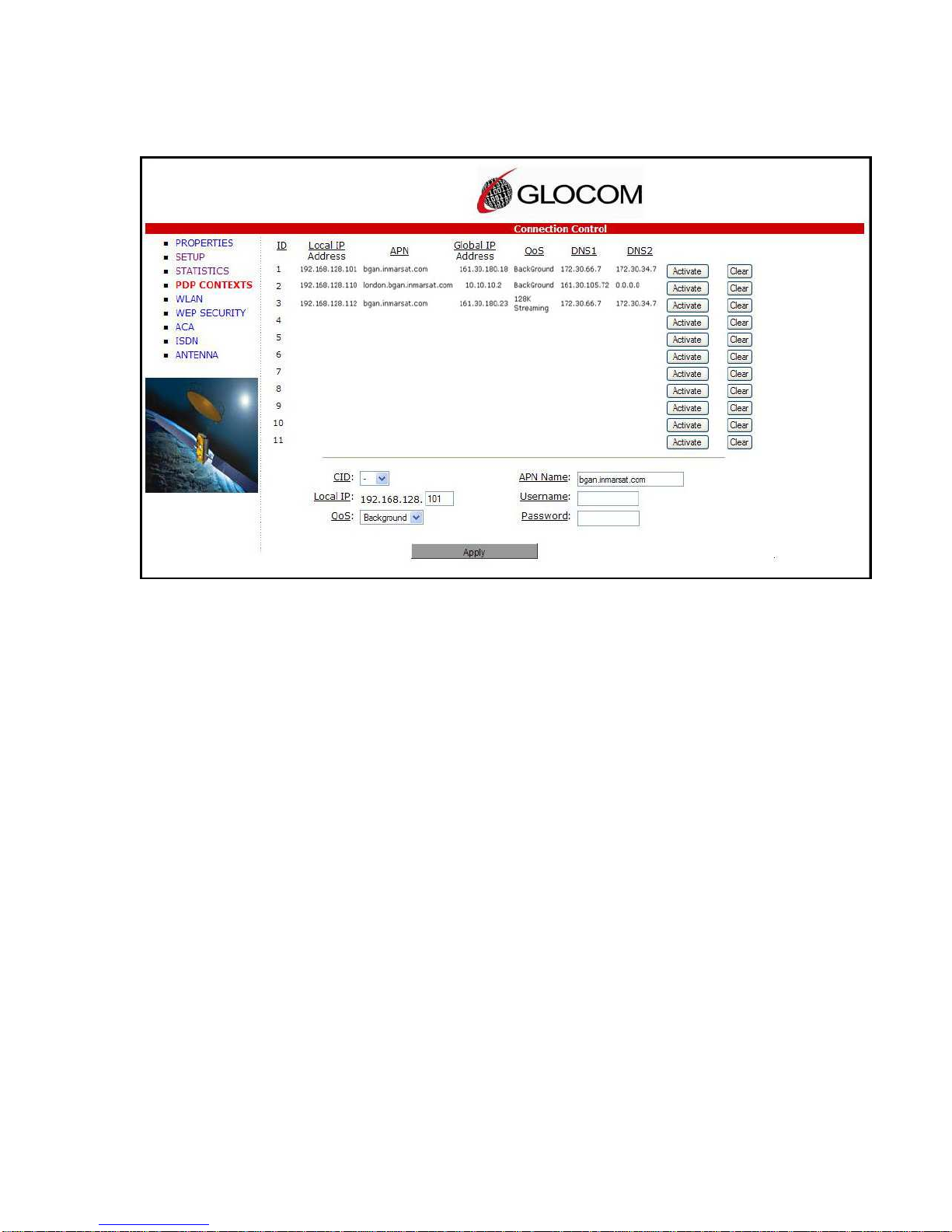
PDP CONTEXTS
The PDP Context page allows the User to setup and configure PDP contexts for any PC or other TE that
is connected to the GX-9. To activate a PDP Context, go to the bottom of the page. You will see the
CID, Local IP Address, APN, Requested QoS, Username and Password fields.
1. CID:
CID: The CID of each context is automatic by default. If for some reason the User wants to
CID:CID:
assign a particular context to a specific CID, use the drop down arrow and select the desired
CID number. Most users will not
2. Local IP Address:
Local IP Address: This is the local IP address of the PC or other TE that you want to setup a
Local IP Address:Local IP Address:
PDP context for. Note that the first three octets of the IP address will reflect any changes
made in the setup screen to the GX-9 local IP address. You can use the “ipconfig” command
from a “cmd” window to find the IP address of a PC.
3. APN name:
APN name: This field is configurable, but it will always show the default APN that has been
APN name:APN name:
provisioned on the USIM. If you have a USIM that has been provisioned with multiple APN’s,
you can type in any of these secondary APN names as part of the PDP context setup.
4. Requested QoS:
Requested QoS: The drop down list shows all of the different QoS types: background,
Requested QoS:Requested QoS:
streaming 32K, streaming 64K, streaming 128K, and streaming 256K. Select the appropriate
QoS required for the PDP context that you are setting up.
Glocom GX-9 (FB250 Class) Operating Manual 15
not need to change this field from the automatic default setting.
notnot

5. Username (UN)/Password (PW):
Username (UN)/Password (PW): Some Service Providers require a Username and Password
Username (UN)/Password (PW):Username (UN)/Password (PW):
to be used when setting up a PDP context. This is often required when using a Static Global
IP addresses assigned by the Service provider.
Activating a PDP Context:
Activating a PDP Context:
Activating a PDP Context:Activating a PDP Context:
To activate a PDP context, perform the following procedure:
Do not modify the CID field unless you need to setup a specific ID for one of your devices. Leaving it
blank will allow the software to automatically choose the next CID that is available.
Next, type in the local IP address of the device that you want to setup the connection for. The APN is
read from the USIM card and is usually not changed unless you have more than one APN provisioned on
the USIM card.
Next, select the QoS that is needed by selecting it from the drop down list.
If your Service Provider requires a UN and PW, enter it in the Username and Password boxes, then click
on “Apply”.
The new connection will show up in the table above (See screen shot below for example).
Background Context activated for 192.168.128.101
Background Context activated for 192.168.128.101
Background Context activated for 192.168.128.101Background Context activated for 192.168.128.101
16 Glocom GX-9 (FB250) Operating Manual

Once the context has been setup, whether it is successful or not, the context field will always be
populated until you click on the “Clear” box. This allows you to be able to retry/reactive the existing
context parameters (See CID #1 below).
You can determine if a context is active by looking to see if the Global IP Address and DNS fields are
populated. If they are populated, the context is active.
Glocom GX-9 (FB250 Class) Operating Manual 17
CID #1 Inactive; CID #2 & 3 active
CID #1 Inactive; CID #2 & 3 active
CID #1 Inactive; CID #2 & 3 activeCID #1 Inactive; CID #2 & 3 active

Activating Multiple PDP Contexts
Activating Multiple PDP Contexts
Activating Multiple PDP ContextsActivating Multiple PDP Contexts
To activate multiple PDP contexts for additional TE devices, follow the same procedures above. Each
time you activate a context for a particular local IP address, it will show up in the table as shown in the
screenshot below.
18 Glocom GX-9 (FB250) Operating Manual

WLAN
CCCCONNECTING BY
ONNECTING BY WLAN
ONNECTING BY ONNECTING BY
If you have not previously used the terminal’s WLAN interface, it must be enabled using the web MMI,
with your PC connected to the terminal via the Ethernet interface.
Wireless LAN interface enabled/disabled: The default is disabled.
Network (SSID) name: The default is “BGAN” but you can change it to whatever you prefer.
Channel number: This controls the radio channel number (1-14) used by the access point. Depending on
the country only certain subsets of these channels may be used (3 options: France, Spain or Rest of the
World). Channel 11 is common to almost all countries, so it is used as the default.
WLAN
WLANWLAN
Glocom GX-9 (FB250 Class) Operating Manual 19
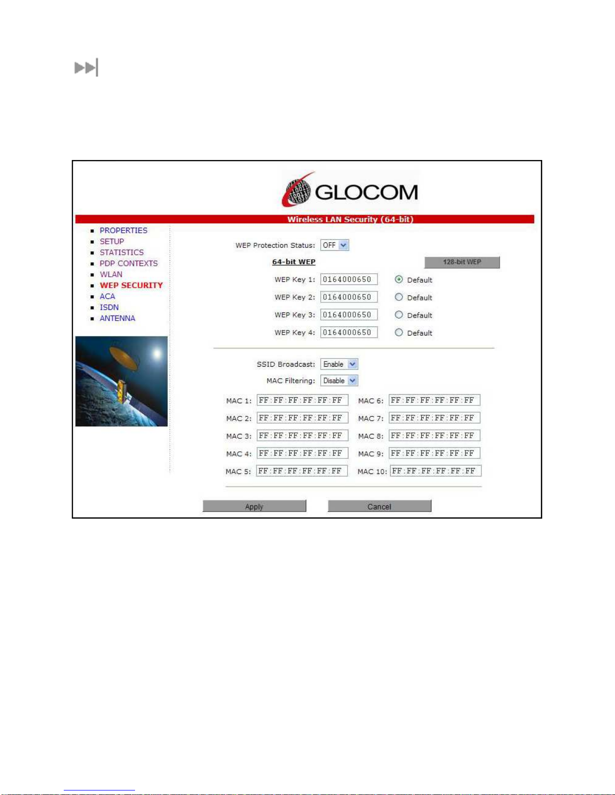
WEP SECURITY
WEP Protection Status:
WEP Protection Status: Click “On” from the drop down list to enable the Wireless Encryption Protocol
WEP Protection Status:WEP Protection Status:
(WEP) for added security. When the terminal’s WLAN interface is enabled, the WLAN LED is either green
(WEP is enabled) or red (WEP is not enabled). When the LED is red, any computer with a WLAN
interface can detect the terminal’s WLAN SSID, and connect to it automatically.
Encryption Level:
Encryption Level: 64 or 128 bit WEP encryption can be enabled.
Encryption Level: Encryption Level:
WEP Key 1:
WEP Key 1: Default WEP keys are formulated using the IMEI number of the terminal. If you want to use
WEP Key 1: WEP Key 1:
different WEP keys, please use the following table as a reference when entering the new WEP keys:
Hexadecimal 128-bit: Requires 26 characters. Recommended
Hexadecimal 64-bit: Requires 10 characters
Note:
Note: If WEP is enabled, you must provide WLAN users with the proper WEP key in order for them to
Note:Note:
connect to the GX-9 terminal. Please write down the WEP key that you use because once entered, there
is no way to view this key again. You will have to disable WEP, reboot the terminal and reset it if the
WEP key is forgotten.
SSID Broadcast:
SSID Broadcast: For added security you can choose not to broadcast your SSID.
SSID Broadcast: SSID Broadcast:
20 Glocom GX-9 (FB250) Operating Manual
Recommended
RecommendedRecommended

MAC Filtering:
MAC Filtering: For added security, click on ENABLE from the drop down list. Then choose up to 10
MAC Filtering: MAC Filtering:
selected MAC addresses that will be allowed to connect to your WLAN. Note
address of a PC or other TE, go to the DoS prompt and enter ipconfig /all.
Note: To determine the MAC
NoteNote
Glocom GX-9 (FB250 Class) Operating Manual 21

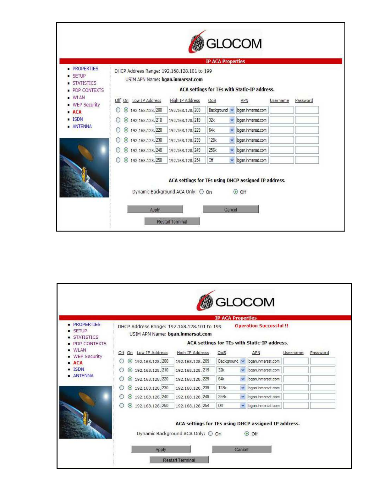
ACA
This web page allows you to use Automatic Context Activation (ACA) in either of two ways;
1)using static IP addresses in the PC or other TE device to establish an automatic PDP context with
any QoS that is offered by the network (upper half of the web page) or
2) using the DHCP from the GX-9 and establishing an automatic background PDP context for any PC
or other TE that connects to the GX-9 (lower part of the web page).
ACA settings for TEs with Static IP address:
ACA settings for TEs with Static IP address:
ACA settings for TEs with Static IP address:ACA settings for TEs with Static IP address:
You can esteblish a range of static IP addresses for setting up an automatic PDP context with any of
the QoS’s offered by the network.
To turn on a particular range of addresses, select the “On” radio button and choose a range of
addresses, low and high to use (e.g. 192.168.128.1 to 192.168.128.10).
Next select the desired QoS for that range of IP addresses (e.g. 32K streaming). The APN listed is
the default APN read from the USIM card (bgan.inmarsat.com). If your USIM is provisioned for more
than one APN, then you can type a secondary APN in this field.
Next, if your Service Provider requires a UN and PW, enter it in the next two fields.
22 Glocom GX-9 (FB250) Operating Manual
To setup additional ranges of addresses, follow the same instructions as above. Note:
ranges can not overlap.
When you are finished, click on “Apply” and “Operation Successful” will be displayed.
Note: IP address
Note: Note:
ACA s
ACA settings for
ettings for PCs and other
ACA sACA s
ettings for ettings for
the GX-9 for dynamic background ACA. In this mode any device connected to the GX-9 will
automatically receive a background PDP context.
To activate this feature, select the “On” radio button under ACA settings forPCs or other TEs using
DHCP assigned IP address and click on “Apply”.
PCs and other TEs using DHCP assigned IP address:
PCs and other PCs and other
TEs using DHCP assigned IP address: This option allows setting up
TEs using DHCP assigned IP address: TEs using DHCP assigned IP address:
Glocom GX-9 (FB250 Class) Operating Manual 23
To determine if the context has been setup properly, click on PDP Contexts page and this will display
all contexts that have been setup (active or inactive). See screen shot below.
24 Glocom GX-9 (FB250) Operating Manual

Glocom GX-9 (FB250 Class) Operating Manual 25

ISDN
An ISDN data connection can be established by connecting the ISDN equipment directly to the GX-9s
ISDN port with an ISDN cable (same as an Ethernet cable). This web page allows you to activate 40V
power sourcing on the ISDN interface, and set MSN numbering options.
1. ISDN Power Sourcing:
ISDN Power Sourcing: To turn on the ISDN power sourcing click on the “On” radio button. The ISDN
ISDN Power Sourcing: ISDN Power Sourcing:
device will receive 40V power immediately via the ISDN cable. This field should be On unless ISDN is
never required or the ISDN device has its own power source.
2. MSN Speech:
MSN Speech: By default, MSN 1 is entered into the MSN Speech number text box. To receive
MSN Speech:MSN Speech:
incoming calls, first program the same MSN into the ISDN handset that connected to the GX-9’s
ISDN port.
3. MSN 3.1 KHz audio:
MSN 3.1 KHz audio: By default, MSN 2 is entered into the MSN 3.1 KHz Audio number text box. To
MSN 3.1 KHz audio: MSN 3.1 KHz audio:
receive incoming calls, program the same MSN into the ISDN fax machine connected to the ISDN
port.
4. MSN UDI (Unrestricted Digital Information
MSN UDI (Unrestricted Digital Information):
MSN UDI (Unrestricted Digital InformationMSN UDI (Unrestricted Digital Information
UDI is a 64 Kbps service that is the European standard for ISDN.
5. MSN RDI (Restricted Digital Information):
MSN RDI (Restricted Digital Information): By default, MSN 3 is entered into the MSN RDI text box.
MSN RDI (Restricted Digital Information):MSN RDI (Restricted Digital Information):
RDI is a 56 Kbps service that is normally found in the USA.
): By default, MSN 3 is entered into the MSN UDI text box.
): ):
26 Glocom GX-9 (FB250) Operating Manual

6. Trigger for Mobile
Trigger for Mobile----Originated call type (Bearer):
Trigger for MobileTrigger for Mobile
terminal to select the bearer type for mobile originated calls. By default, “Bearer capability” is set as
the trigger in this text box. There is also an option under the drop down arrow to set the trigger to use
the MSN rather than the bearer. Most ISDN devices correctly signal the call type (speech, 3.1KHz
audio, UDI, RDI) via the bearer capability. If there is a problem, this field can be changed to use the
MSN number instead.
Originated call type (Bearer): This box controls the mechanism used by the
Originated call type (Bearer): Originated call type (Bearer):
Once all changes have been made, click on “Apply”. Any changes to this screen require a re-boot of the
terminal to save the new configuration. Use the power button on the GX-9 or the “Restart Terminal”
button to gracefully re-boot the GX-9.
Note:
Note: Different MSNs can be used for any of the ISDN call types above, but the ISDN equipment must be
Note:Note:
programmed with the same MSN to accept incoming calls, and different numbers must be used for
speech, audio and UDI/RDI calls.
Glocom GX-9 (FB250 Class) Operating Manual 27

ANTENNA
This web allows monitoring the status of the antenna.
Note:
Note: This page does not automatically update and must be refreshed to poll for the latest status.
Note:Note:
ATB State:
ATB State: This field indicates the detailed state of the antenna tracking board and indicates whether
ATB State: ATB State:
the antenna is tracking or searching for the satellite
Elevation:
Elevation: the current elevation angle of the antenna
Elevation: Elevation:
Frequency (KHz):
Frequency (KHz): the frequency of the global beam in kHz that the antenna is tracking
Frequency (KHz): Frequency (KHz):
Antenna Tracking:
Antenna Tracking: indicates (TRUE or FALSE) whether or not the antenna is currently tracking the
Antenna Tracking: Antenna Tracking:
satellite
28 Glocom GX-9 (FB250) Operating Manual

Additional Information on the various antenna parameters (ATB states) are shown below:
#### State name
0 INIT_ST Initial state
1 IDLE_ST Wait on a frequency from the TU
2 AZ_SEEK1_ST Determine min/max signal levels in a full sky scan
3 AZ_SEEK2_ST Find azimuth direction
4 AZ_SEEK_ELEVATION_ST Determine min/max signal levels on a single elevation
5 TR_TUNE_EL_ST Track and tune elevation state
6 TR_TUNE_PLL_ST Track and tune PLL state
7 TRACK_ST Track state
8 BLOCK_ST Blocked state
9 FREEZE_ST Antenna has stopped all motors
10 0x0A) TEST_ST Test state
The field at the bottom of the page is true/false indicating whether the antenna is tracking (i.e. in states 5,
6 or 7).
The frequency is the frequency of the global beam. Possible values are the primary and secondary
State name State Description
State name State name
State Description
State DescriptionState Description
frequencies of the 3 satellites.
Satellite ID Satellite Primary Alternate
Longitude Freq kHz Freq kHz
I4-F1 IOR 64.0 E 1537485 1540825 Old position
I4-F1 APAC 143.5 E 1537485 1540825 New position
I4-F2 AOR 53.0 W 1537920 1541115 Old position
I4-F2 EMEA 25.0 E 1537920 1541115 New position
I4-F3 AMER 98.0W 1537070 1540730 New Satellite
Glocom GX-9 (FB250 Class) Operating Manual 29

TTTTR
ROUBLE
OUBLE S
RR
Problem
Problem Possible Cause
ProblemProblem
OUBLE OUBLE
Possible Cause Possible Solution
Possible CausePossible Cause
SHOOTING
HOOTING
SS
HOOTINGHOOTING
Possible Solution
Possible SolutionPossible Solution
Terminal will not turn on DC power adapter not connected properly.
User disabled the Auto “On” Mode.
Cannot insert USIM card
holder into terminal
The BGAN LaunchPad or
web MMI will not connect
to the terminal
USIM is not correctly seated in the card
holder
Card holder incorrectly oriented
No interface connection between the
terminal and computer
Check DC power adapter
connection points
Use LaunchPad or web MMI to
enable the Auto “On” Mode.
Ensure the USIM is pressed firmly
into the card holder
Ensure the card holder is oriented
as shown in First Time Setup
Ensure there is a WLAN or Ethernet
connection between the terminal
and computer, see User Guide
First Time Setup
First Time SetupFirst Time Setup
User Guide
User GuideUser Guide
Static IP address has been setup in your
laptop and will not accept the terminal
DHCP address.
The BGAN LaunchPad will
not connect to the terminal
over the WLAN interface
30 Glocom GX-9 (FB250) Operating Manual
WLAN WEP is enabled on terminal and the
computer’s WLAN is not programmed with
the WEP keys
WLAN signal is not strong enough
Check the IP configuration settings
on your laptop
Disable WEP, or use the same
WEP keys for both the terminal and
computer. For details, review the
User Guide
User Guide
User GuideUser Guide
Locate the terminal and computer
closer together and reduce any
obstructions between them.

Problem
Problem Possible Cause
ProblemProblem
Possible Cause Possible Solution
Possible CausePossible Cause
Possible Solution
Possible SolutionPossible Solution
Terminal will not accept
incoming ISDN calls
Terminal will not make
outgoing ISDN calls
The MSN programmed into the ISDN device
does not match the MSN programmed into
the terminal
ISDN power sourcing is turned off
Terminal is not Registered with the Network
and still in antenna pointing mode. “Bypass
antenna pointing” may be turned off.
Ensure the appropriate MSN is
programmed into the ISDN device,
see ISDN Section of User Guide
Ensure the appropriate MSN is
programmed into the terminal, see
ISDN Section of User Guide
Enable the ISDN power sourcing
from the BGAN LaunchPad or ISDN
web MMI page (unless the ISDN
device has a separate power
source).
Check Setup page in web MMI to
make sure “Bypass antenna
pointing” is turned ON.
User Guide
User GuideUser Guide
User Guide
User GuideUser Guide
Terminal is connected to
the BGAN network, but
cannot obtain the
requested Quality of
Service
Terminal does not obtain a
GPS fix
You hear a loud beep from
the terminal when you
connect an ISDN device to
the ISDN port
Network temporarily not available
User tried to set up a 256 Kbps streaming
connection.
Terminal’s location limits visibility of 4 or
more GPS satellites.
The ISDN device is trying to draw too much
power from the satellite terminal’s ISDN
interface
The device you are connecting is not an
ISDN device. It might be an Ethernet device
that you are accidentally connecting to the
Retry again. If problem persists,
contact your service provider.
The Inmarsat Network only
supports 256 Kbps streaming
connections from terminals that
have an elevation angle greater
than or equal to 45 degrees.
Move the vessel to a location where
there are no obstructions.
Only connect an ISDN device that
draws less than 70mA of current at
40V (equivalent power 2.8W)
Make sure you connect only ISDN
devices to the ISDN port
ISDN port.
Glocom GX-9 (FB250 Class) Operating Manual 31

Problem
Problem Possible Cause
ProblemProblem
Possible Cause Possible Solution
Possible CausePossible Cause
Possible Solution
Possible SolutionPossible Solution
None of the above
solutions resolve the
problem
Terminal may have a hardware or software
fault, and needs to be re-booted.
Remove DC power adapter. Wait
30 seconds. Reconnect the DC
power and turn on the terminal.
32 Glocom GX-9 (FB250) Operating Manual

TTTTECHNOLOGY
ECHNOLOGY O
ECHNOLOGY ECHNOLOGY
GPS
The Global Positioning System (GPS) uses 24 orbital satellites to determine the position of the Terminal
anywhere on the globe.
OOOOBTAINING A
BTAINING A GPS
BTAINING A BTAINING A
In normal operation, a GPS receiver, such as that built in to the Tracking Antenna, needs to be able to
receive signals from at least four satellites so that it can then calculate a latitude, a longitude and an
altitude – this position fix is referred to as a 3-dimensional or 3-D fix. If only three GPS satellites can be
seen by the GPS receiver, then the last available altitude measurement is assumed and the GPS receiver
calculates a position fix based on latitude and longitude only. This simpler position fix is referred to as a 2-
GPS
GPSGPS
F
FIX
FF
IX
IXIX
OVERVIEW
VERVIEW
OO
VERVIEWVERVIEW
dimensional or 2-D fix and is quicker and easier to obtain than a 3-D fix, but may be less accurate.
The GPS receiver may take between a few seconds and 20 minutes to obtain a GPS fix, depending on
how frequently the GPS receiver is being used. The frequency of use determines the how quickly the
GPS Terminal is able to start.
Hot start
Hot start − if the GPS receiver is being used frequently, (that is, in the last two hours), it is regularly
Hot startHot start
updated with data from the GPS satellites, and so only takes a few seconds to obtain a GPS fix after
being switched on.
Warm start
Warm start − if a GPS receiver has not been used for more than two hours, then it will take up to 45
Warm startWarm start
seconds to obtain a GPS fix.
Cold start
Cold start − if the GPS receiver has not been used for some time or is 300 km or more from where it was
Cold startCold start
last used, it can take as long as 15 minutes to obtain a valid position fix.
The time taken to obtain a valid GPS fix can also be affected by the visibility that the GPS receiver has of
the GPS satellites. The GPS system is relatively tolerant of atmospheric conditions such as heavy cloud
or rainfall. However, physical blockages, such as tall buildings or terrain can significantly degrade the
ability of the GPS receiver to obtain a fix. For this reason, ensure that the GPS receiver has a clear view
of as much open sky as possible.
GPS
GPS AND
AND BGAN
AND AND
BGAN
BGANBGAN
GPSGPS
BGAN uses the accurate position and timing information obtained from GPS to help ensure efficient
registration of a BGAN Terminal with the BGAN network.
Following successful registration and providing the Terminal is left switched on and remains stationary,
the GPS is no longer needed. Periodically, the BGAN Terminal contacts the BGAN network to inform the
Glocom GX-9 (FB250 Class) Operating Manual 33
R
REGISTRATION
EGISTRATION
RR
EGISTRATIONEGISTRATION

network that it is still switched on. In addition, the BGAN network periodically checks each Terminal for
activity, and if the Terminal has not automatically contacted the BGAN network as described above, then
the Terminal will be de-registered from the network.
34 Glocom GX-9 (FB250) Operating Manual

ISDN
The Satellite Terminal provides an ISDN (Integrated Services Digital Network) interface to connect
devices for Circuit Switched voice and data services. It is a Basic Rate (also known as 2B+D) interface
and uses the Euro ISDN protocol. Note that the Satellite Terminal can only provide service for one
64Kbps B-channel at a time.
DDDDIALING AND
IALING AND N
IALING AND IALING AND
DIALING
As the ISDN numbering system follows the same pattern as the normal telephone system, dialing is
carried out in exactly the same manner as making a normal telephone call. The subscriber number is
used with the same international and area codes as any other telephone network.
MULTI-SUBSCRIBER NUMBERING (MSN)
ISDN supports Multi-Subscriber Numbering (MSN). MSN is a facility whereby more than one telephone
NUMBERING
UMBERING
NN
UMBERINGUMBERING
number can be allocated to an ISDN line. The BGAN Satellite Terminal assigns different MSNs for Voice,
3.1KHz Audio, UDI and RDI devices. Each incoming call will be directed to the appropriate MSN
depending on the type of call. This allows proper routing of incoming calls to the correct ISDN device (e.g.
ISDN phone, data card or Fax).
PDP CONTEXT
A Packet Data Protocol (PDP) Context defines connection aspects such as routing, Quality of Service
(QoS), security and billing between a mobile user terminal, such as the BGAN Terminal, and a data
network. PDP Contexts are essential to the General Packet Radio Service (GPRS) system, which is used
by GSM and UMTS-based 3G networks worldwide for transmitting data.
In order for a user to be able to transfer data across a network, a PDP Context must be activated in the
Terminal and associated Core Network. The procedure for this is as follows:
1. After registration with the network, the user activates a PDP Context using an application on the
computer or Terminal, and requests sufficient radio resources (that is, power and bandwidth) to
support the context activation procedure.
2. Once the resources are allocated, the Terminal sends the Activate PDP Context request to the Core
Network. This request includes key information about the mobile user's PDP address (for example an
IP address), PDP type (that is, static or dynamic address) the QoS requested for this context, the
APN of the external network to which connectivity is requested, the user's identity (IMSI) and any
necessary IP configuration parameters (for example, security settings).
Glocom GX-9 (FB250 Class) Operating Manual 35

3. On receiving the Activate PDP Context message, the Core Network checks the user's subscription
record to establish whether the request is valid. If the request is valid, a virtual connection is
established between the Terminal and the Core Network, and data transfer can then take place
between the Terminal and the external data network, within the scope of the current PDP Context.
The PDP Context is stored in both the Terminal and the Core Network.
A single Terminal may have multiple PDP Contexts each with different QoS profiles. The primary PDP
Context is a PDP Context with default QoS profile attributes and is always activated first. All other PDP
Contexts with the same PDP Address are secondary PDP Contexts. Secondary PDP Contexts share the
same PDP Address and connect to the same APN but may have different QoS profiles.
36 Glocom GX-9 (FB250) Operating Manual

WLAN
Wireless Local Area Networking (WLAN) enables two or more computers equipped with wireless adapter
cards to share resources.
A wireless network comprises of two or more computers each equipped with wireless adapter cards
forming a network. When the computers are within range of each other each computer has access only to
the resources of the other computer but not to any central server or other resource. This type of basic
configuration is known as an ad hoc network.
A more common and efficient use of a wireless network is one in which two or more computers equipped
with wireless adapter cards are linked to a WLAN Access Point. The Access Point allows each computer
to have access to shared resources, such as a broadband Internet connection, as well as to other
computers on the network. Such a configuration is known as Infrastructure Mode. This is the default
configuration for WLAN in the UT.
PPPPERFORMANCE
ERFORMANCE
ERFORMANCEERFORMANCE
The performance of a WLAN network will be influenced by several factors including the number of users
on the network, the location of the antenna, the distance from the antenna and the degree of blocking
from buildings and other infrastructure. Typical operating ranges are 200-300 meters outdoors and 30-60
meters indoors, the performance degrades gradually as the signal strength decreases.
SSID
SSID
SSIDSSID
A wireless network is identified by a Service Set Identifier or SSID. An SSID is also referred to as a
Network Name because it is a name that identifies a wireless network. Wireless devices that wish to
communicate with each other must be configured with the same SSID. Several Access Points can be set
up using the same SSID so that users can roam from one Access Point to the other without losing
network access. The SSID is broadcast so that any wireless device in range can read the SSID and ask
permission to associate with it. The SSID is not intended as a security measure − it is used only to identify
different networks.
Glocom GX-9 (FB250 Class) Operating Manual 37

TTTTECHNICAL
ECHNICAL S
ECHNICAL ECHNICAL
SPECIFICATIONS
PECIFICATIONS
SS
PECIFICATIONSPECIFICATIONS
Terminal
Weight
Weight 2.8 Kg (terminal with battery) 3.9 Kg
WeightWeight
Dimens
Dimensions
DimensDimens
Humidity
Humidity 95% RH at +40˚C 95% RH at +40° C
HumidityHumidity
Temperature
Temperature -25˚C to +60˚C operating
TemperatureTemperature
Water & Dust
Water & Dust IP-54 standard IP-55 standard
Water & DustWater & Dust
WWWWind
ICE
ICE N/A Up to 25 mm non-operational
ICEICE
Ship
Ship Motions
ShipShip
ions 27.5 cm x 34.5 cm x 5.0 cm Ø33.0 cm x 27.0 cm
ionsions
ind N/A <100 knots under normal operation
indind
Motions N/A Turning Rate: 40°/s
Motions Motions
Terminal (BDU)
TerminalTerminal
-25˚C to +80˚C storage
(BDU) Antenna
(BDU) (BDU)
Antenna (ADU)
AntennaAntenna
-25° C to +55° C operating
-25° C to +80° C survival
(ADU)
(ADU) (ADU)
Power (terminal
Power (terminal
Power (terminal Power (terminal
plus antenna)
plus antenna)
plus antenna)plus antenna)
Max: 100 W (when transmitting)
Idle: 20 W
Turning acceleration 50°/s^2
38 Glocom GX-9 (FB250) Operating Manual

DDDDECLARATION OF CONFOR
ECLARATION OF CONFORMITY
Glocom Inc., 22 Firstfield Rd., Ste 125 Gaithersburg, MD 20878 USA,declares under our sole
responsibility that the product GX-9 Satellite IP Terminal to which this declaration relates, is in conformity
with the following standards and/or other normative documents:
ETSI EN 301 444 , ETSI EN 300 328, ETSI EN 301 489-1, ETSI EN 301 489-3, ETSI EN 301 489-17,
EN62311, EN 60950-1, Council Recommendation 1999/519/EC.
We hereby declare that all essential radio test suites have been carried out and that the above named
product is in conformity to all the essential requirements of R&TTE Directive 1999/5/EC.
The conformity assessment procedure referred to in Article 10 and detailed in Annex [III] or [IV] of
Directive 1999/5/EC has been followed with the involvement of the following Notified Body(ies):
PHOENIX TESTLAB GmbH, Kӧnigswinkel 10, D-32825 Blomberg, Germany.
ECLARATION OF CONFORECLARATION OF CONFOR
MITY
MITYMITY
Identification mark: 0700
The technical documentation relevant to the above equipment will be held at:
Glocom Inc.
Signed by JD Pan (Managing Director, August , 2009)
Note
Note The Ethernet cable used with the GX-9 shall not be longer than 3 meters to comply with
NoteNote
This device conforms to the FCC rules. Any changes or modifications to Glocom’s equipment, not
expressly approved by Glocom Inc., could void the user's authority to operate the equipment.
To comply with FCC RF exposure requirements, this device must be operated with a minimum separation
distance of 20 cm or more from a person's body. Other operating configurations should be avoided.
This device complies with Part 15 of the FCC Rules. Operation is subject to the following two conditions;
,,,,
ETSI emissions requirements.
FCC COMPLIANCE
0700 (Notified Body number).
07000700
22 Firstfield Rd., Ste 125 Gaithersburg, MD 20878 USA
(1) this device may not cause harmful interference, and (2) this device must accept any interference
received, including interference that may cause undesired operation.
Glocom GX-9 (FB250 Class) Operating Manual 39

IRECTIVES
EU WEEE (WASTE ELECTRICAL AND ELECTRONIC EQUIPMENT) D
The European Union (EU) directive on waste electrical and electronic equipment mandates recycling of electrical
and electronic equipment throughout the EU by August 13, 2005.
Unless otherwise noted, all products, assemblies, and sub-assemblies manufactured by Glocom Inc., and its subcontractors will be compliant with this directive and any subsequent revisions or amendments. This product
carries the WEEE label below to demonstrate compliance.
For addition information, contact Glocom Inc., at: www.glocom
www.glocom----us.com
www.glocomwww.glocom
us.com
us.comus.com
40 Glocom GX-9 (FB250) Operating Manual

GGGGLOSSARY
LOSSARY
APN: An Access Point Name (APN) provides access to an external network. By default, the SIM Card in
your terminal is configured with the APN of your Service Provider. You may want to configure further
APN’s if you have arranged with your Service Provider to use more than one SIM Card.
BGAN Satellite Terminal: Referenced throughout this document as the Satellite Terminal, “The
Terminal,” or UT. This device implements and manages BGAN satellite communications between
your computer and Service Provider’s network.
Quality of Service: Quality of Service (QoS) assigns a level of priority to certain types of data traffic, in
particular high bandwidth applications such as video and multimedia. QoS attempts to maintain a
guaranteed throughput level, and minimize error rates and end to end latency, so providing a higher
level of service than "best effort" protocols.
DNS Server: The Domain Name System (DNS) is an Internet service that is required because the
Internet does not recognize the text-based Web address or email address that you type into your
Web browser or email application. All or part of a Web address or an email address is a domain
name, and DNS translates this domain name into an IP address that is recognized by the Internet.
A DNS Server holds a database of domain names and IP addresses, so that when you enter a Web
address or email address, you are directed to the correct IP address over the Internet.
LOSSARYLOSSARY
Dynamic DNS Server: If you are using dynamic IP addressing, Inmarsat recommends that you use a
dynamic DNS server. A dynamic DNS server updates the IP address information in the DNS
database each time your IP address changes. A dynamic DNS server also enables a computer
using a dynamic IP address to use network applications that normally require a static IP address,
for example FTP servers. This service requires subscription with a Dynamic DNS provider.
Static DNS Server: If you are using static IP addressing, Inmarsat recommends that you use a static
DNS server. If you select this option, you must enter the IP address of the Primary DNS Server.
This is supplied by your Internet Service Provider. Optionally, you can enter the IP address of a
Secondary DNS Server, also supplied by your ISP. This is used in the event of failure of the
Primary DNS Server.
Error correction: Error correction ensures that very little data is lost during transfer by asking for dropped
packets to be resent. However, because it holds subsequent data whilst the packet is being resent,
you may notice some jitter or delay in the received data. This is normal for most data types.
For real-time applications, such as Voice over IP (VoIP) or video, it is recommended that you remove
error correction. Removing error correction minimizes delay and jitter..
Ethernet: Ethernet is a local area networking method used widely throughout the computer industry. It is
one of the three communications interfaces supported by the Satellite Terminal.
Fault Code: A number which uniquely references an error in a hardware or software system. In the
Satellite Terminal, if there is a fault detected, the fault code and a description are displayed in suitable
LaunchPad windows.
GPS: Global Positioning System. The GPS receiver in the Satellite Terminal receives signals from the
constellation of GPS satellites. It uses these signals to determine the Terminal’s location on earth.
That location is used during registration to gain access to the BGAN system.
Header Compression: A header is the component of a data packet that precedes the data that you are
sending. The header contains information such as source and destination address, error checking
and other administrative details. In most data types this does not noticeably affect the data
transmission rates. However in multimedia applications such as voice and video, the header can
significantly affect performance.
Inmarsat recommends that you switch on header compression for multimedia applications, such as
video.
Glocom GX-9 (FB250 Class) Operating Manual 41

IP Address: An Internet Protocol address, or IP address, is a number that uniquely identifies the
computer accessible over a TCP/IP-based LAN or the Internet that is sending or receiving
information. An IP address is a 32-bit numeric address written as four numbers, separated by periods
and each number is between 0 and 255. For example, 207.115.79.4 is an IP address. In the BGAN
system, IP addresses for the Network and the TE can be dynamic or static.
Network Dynamic IP Address: A network dynamic IP address is a temporary address that is
assigned by your BGAN Service Provider when you connect to the BGAN Network. If you do not
need a permanent Static IP address, most Service Providers use a dynamic IP address. Some
Service Providers provide a private Network IP address not routable within the Internet) and
others provide a routable public IP address.
Static IP Address: A static IP address is assigned by Service Providers to BGAN Users when the
USIM is provisioned. This static IP address is used every time you connect to the BGAN network
and is associated with a specific Username and Password.
DHCP Address: Local IP address that is assigned by the UT DHCP server to the TE once
connected to the UT. This is a private IP address that is not routable within the Internet.
Terminal Local IP Address: IP address of the UT to access the web MMI and talk to the UT via
Telnet. This address is configurable by the User.
Standard Connection: A standard connection is charged by volume of data sent. The bandwidth you are
allocated depends on terminal type and network availability, but is always ‘best effort’, that is, you are
allocated bandwidth depending on your requirements and the requirements of other users of the
BGAN network, or BGAN Terminal. This connection class is suitable for most data types, other than
multimedia.
Streaming: A streaming connection is charged by time. You are charged for the amount of time the
connection is active. Streaming enables multimedia data, such as video, to be sent in a continuous
data stream and converted into sound and pictures. The bandwidth required for a streaming
connection is difficult to predict, and depends on factors such as length of connection and number of
receivers.
Symmetrical Rate: The rate at which streaming data is transmitted, in kilobits per second (Kbps). This
rate applies to transmitted (uplink) and received (downlink) data.
Desired Symmetrical Rate: From the drop-down list, choose the desired data rate for your
Streaming connection. This can be 32 Kbps, 64 Kbps, 128 Kbps or 256 Kbps. This figure is
guaranteed, unless the connection cannot meet this requirement because of bandwidth
restrictions. In this case the rate defaults to the minimum symmetrical rate.
Minimum Symmetrical Rate: From the drop-down list, choose the minimum data rate that you are
prepared to accept for your Streaming connection. This can be 32 Kbps, 64 Kbps, 128 Kbps or
256 Kbps. This rate must be lower than the Desired Symmetrical Rate. If the connection cannot
meet this requirement, an error message displays.
TE (Terminal Equipment): Terminal equipment refers to the piece of equipment that is connected to the
BGAN UT (e.g. laptop, video equipment, phone, etc.)
Traffic Flow Template: A Traffic Flow Template, also called an Application Template, is a series of data
filters such as QoS (Quality of Service), PDP Context and security settings, that allow the Core
Network to classify packets received from an external network into the correct PDP Context. When
incoming data arrives at an access point in the core network, a packet classifier will make a PDP
Context selection based on the Traffic Flow Template, and map the incoming data packets into the
PDP Context with the correct QoS attributes. The use of a Traffic Flow Template allows multiple PDP
Contexts to be associated with the same PDP address.
UT (User Terminal): The User terminal is the BGAN modem device
USIM Card: Your BGAN Service Provider supplies you with a Universal Mobile Telecommunications
System Subscriber SIM (USIM) Card.
The USIM card is similar to the SIM Card that is commonly used in a GSM phone. The card holds a
microchip that stores information and encrypts voice and data transmissions, making it extremely
42 Glocom GX-9 (FB250) Operating Manual

difficult to listen in on calls. The USIM Card also stores data that identifies the caller to the BGAN
Service Provider.
Virtual Private Network: A Virtual Private Network (VPN) enables remote offices or users to gain secure
access to their organization's network over the public telecommunications network. This provides the
benefits of remote access without the expense of dedicated leased or owned lines. VPNs work by
using tunneling protocols, such as L2TP, to encrypt data at the sending end, and decrypt the data at
the receiving end. This "tunnel" cannot be accessed by data that is not properly encrypted.
Glocom GX-9 (FB250 Class) Operating Manual 43
 Loading...