


OPERATION MANUAL
DEDICATED VIDEO INTERFACE SERIES
IN2022 High Resolution Video Interface
for VGA and MAC Computers

TABLE OF CONTENTS
Product Overview 2 - 3
Description / Product Features........................................................................................................................2
Input Compatibility / Output Compatibility ....................................................................................................3
Installation 3 - 5
Diagram #1 - IN2022 Installation....................................................................................................................5
External Controls 6 - 7
Horizontal Position Control ............................................................................................................................6
Sharpness Control...........................................................................................................................................6
Gain Control....................................................................................................................................................6
Monitor Emulation.......................................................................................................................................... 7
Using the IN2022 With a Local Monitor ..........................................................................................7
Using the IN2022 Without a Local Monitor.....................................................................................7
Monitor Emulation Chart..................................................................................................................7
Internal Controls (For Technicians Only) 8 - 12
Opening the IN2022 Case...............................................................................................................................8
Diagram #2 - Internal View.............................................................................................................................9
Blue and Red Gain Controls............................................................................................................................9
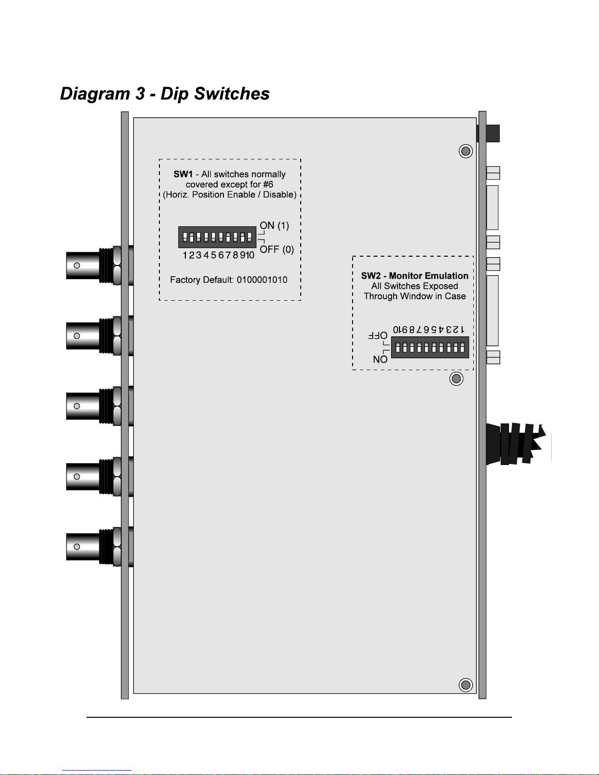
Diagram #3 - Dip Switches ...........................................................................................................................10
Internal Dip Switches..............................................................................................................................11, 12
SW1 - Output Sync / Horizontal Position Control Disable.............................................................11
Select RGB Output or Composite Monochrome Output.................................................................11
Setting Output Sync Format - Automatic or Manual.......................................................................11
SW2 - Monitor Emulation Switches ...............................................................................................12
Technical Reference 12 - 14
VGA and MAC Video Port Pin-Outs............................................................................................................12
Troubleshooting............................................................................................................................................12
Specifications................................................................................................................................................13
Input / Local Monitor Output / Data Display Output......................................................................13
General: Controls / Power Supply / Power Consumption / Dimensions / Weight..........................13
Parts Included .................................................................................................................................13
Optional Accessories.......................................................................................................................13
Warranty........................................................................................................................................................14

2
PRODUCT OVERVIEW
DESCRIPTION
The IN2022 is a high performance dual function computer video interface for VGA-type and
MAC II-type video signals. Like other INLINE interfaces, the IN2022 carries out three primary
functions. This first function is signal splitting as the interface allows for the simultaneous
connection and viewing of both the computer’s local monitor and a second display device such as
a large data monitor or data projector. The second function is physical interfacing and adaption.
The IN2022 connects to VGA PC compatible computers or Macintosh family computers with
15-pin D video connectors and provides output signal on standard BNC connectors. The final
function is electronic interfacing. The interface accepts video in a wide variety of sync formats
and converts the signal to RGsB, RGBS, or RGBHV as required by the display device, cabling,
and video routing system.
PRODUCT FEATURES
• Universal Compatibility for VGA and MAC II Computers- The IN2022 was designed
as the ultimate VGA / MAC video interface, offering input compatibility with the following
standards at resolutions up to 2000 x 2000:
VGA Type VGA, SVGA, XGA, XGA2
MAC II Type MAC II, Quadra, Centris, Performa, Power MAC, Daystar MP, Radius
• Exceptional Video Performance - Featuring advanced video amplification circuitry, the
IN2022 offers video bandwidth in excess of 230 MHz, ensuring that even the highest
resolution VGA and MAC modes will be interfaced with complete signal clarity.
• Buffered Local Monitor Output - Ensures highest quality display on the local monitor.
This buffered output provides the flexibility to place the local monitor anywhere since the
local monitor cable may be extended if necessary.
• Automatic Output Sync Format Selection - The IN2022 senses the number of cables
connected to the output at power up and automatically sets the output sync format to
RGBHV, RGBS or RGsB. LED indicators located next to the Green, H/Comp Sync, and V
Sync output BNCs provide clear visual confirmation of the current output sync format.
• Flexible Monitor Emulation - The interface is set at the factory to pass all sense pins
through to the local monitor, ensuring that the graphics card sees the sense signals from the
attached monitor and sets itself to the appropriate resolution, refresh rate or frequency.
For applications where the IN2022 will be used without a local monitor, dip switches are
provided to emulate virtually any monitor.
• Multi-Step Sharpness Control - optimized to provide maximum visible sharpness
enhancement with high resolution video signals.
IN2022 OPERATION MANUAL - REV 1.1 12/11/99 ©1995 - INLINE, INC.

INPUT COMPATIBILITY
The IN2022 will accept high resolution video signals from VGA video cards with a 15-pin HD
connector or MAC II-type video cards with a 15-pin D video connector. Input signal
compatibility parameters are listed below.
Video Signal: Analog RGB Video
Connector: VGA: 15-Pin HD female video port on computer
MAC: 15-Pin D female video port on computer
Signal format: RGsB, RGBS, RGBHV, RGBSHV, RGsBS, RGsBSHV
Horizontal Frequency Range: 20 KHz to 130 KHz
Vertical Refresh Rates: 30 Hz to 120 Hz
OUTPUT COMPATIBILITY
The IN2022 outputs an analog RGsB, RGBS, RGBHV or Composite Monochrome signal on
female BNC connectors. This output signal is compatible with high resolution data grade
monitors and data / graphics projectors. PCs and MACs operate in several video modes
encompassing a wide range of resolutions and scan rates, and many of the video signals from the
newest models may have very high scan rates (60 KHz or more) and very high resolution (1280 x
1024 is common). The data projector or monitor must be compatible with the horizontal scan
rate and vertical refresh rate of the computer’s video signal. Please check the documentation for
both the computer graphics card and the data display device to ensure compatibility.
3
The IN2022 is not a scan converter or encoder. This unit does not change the horizontal
scan rate, resolution, or convert the signal to NTSC composite video. The display device
connected to the IN2022 output must be compatible with the horizontal scan rate, vertical
refresh rate and resolution of the workstation video signal.
INSTALLATION
Installation steps are listed below and outlined in Diagram 1 on page 5.
#1 Turn the computer and computer monitor off.
Disconnect the computer monitor from the computer’s video port.
#2 Check the Monitor Emulation dip switch settings on the bottom side of the IN2022.
Using Local Monitor - If you are using a local monitor (most installations) make sure
that all dip switches in the box labeled MONITOR EMULATION are set to “0”.
No Local Monitor - If you are not using a local monitor, gently set the dip switches
using the Inline tool provided according to the chart found on page 7.
Check the Monitor Emulation chart and dip switch settings carefully. An improper
setting of the emulation dip switches may lead to improper operation and could even
result in severe damage to the computer video port or the monitor. If you are in doubt as
to which monitor emulation to choose, set all the Monitor Emulation dip switches to “0”
and connect a local monitor.
©1995 - INLINE, INC. IN2022 OPERATION MANUAL - REV 1.1 12/11/99
4
#4 Connect the IN2022 input cable to the computer’s video port.
The input cable is the 4’ long “Y” cable permanently attached to the interface. Connect one of
the connectors on this cable to the computer’s video port as detailed below.
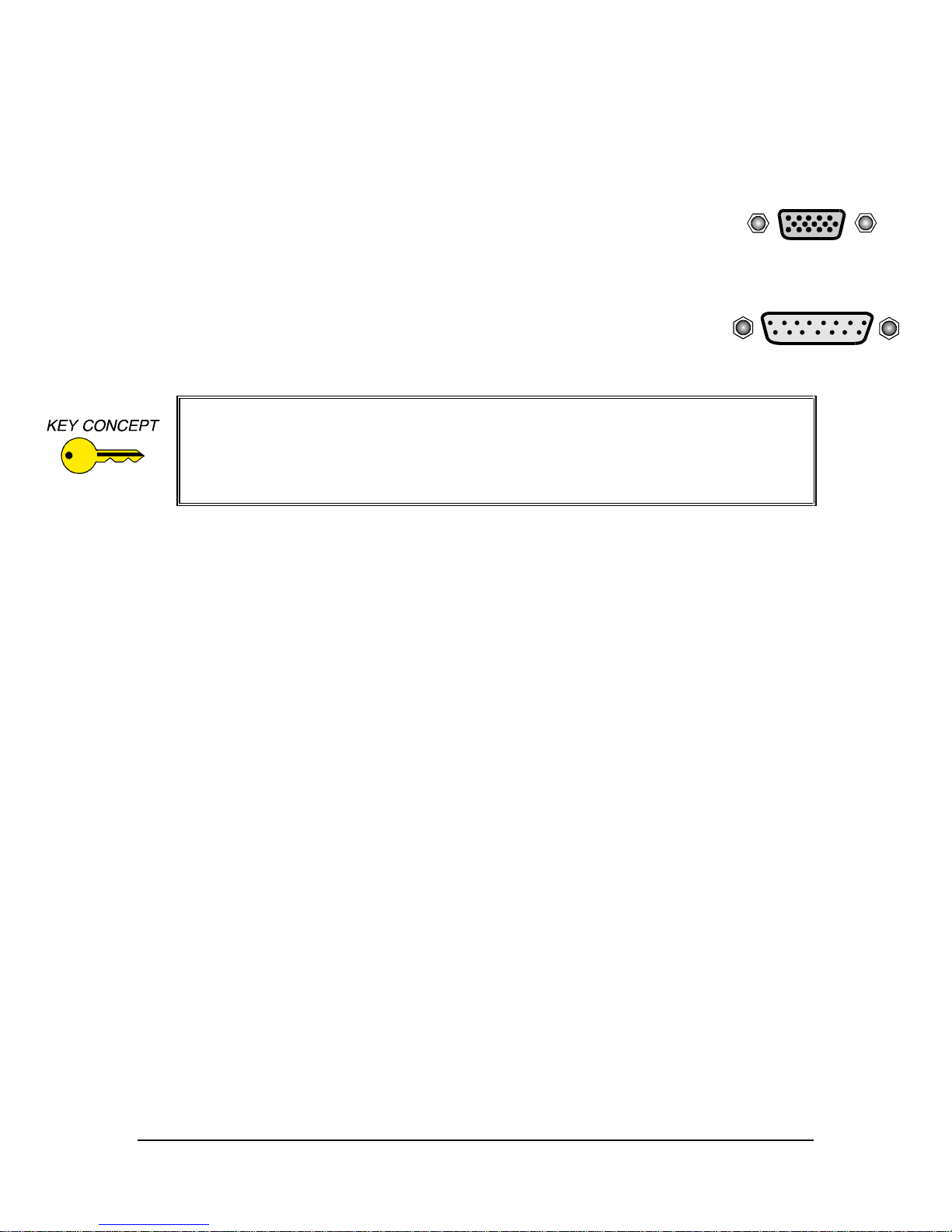
PC Compatible Computers (VGA)
Locate the video port on the computer, a 15-Pin HD connector which looks like this:
Connect the 15-Pin HD connector on the IN2022 input cable to the computer video
port. Do not connect anything to the MAC input connector (15-pin D).
MAC Computers
Locate the video port on the computer, a 15-pin D connector which looks like this:
Connect the 15-Pin D connector on the IN2022 input cable to the computer video
port. Do not connect anything to the VGA input connector (15-pin HD).
Some MAC computers such as the PowerBook and PowerMAC A/V models have a
proprietary connector which must be adapted to a standard 15-pin D video connector.
This video port adapter is available from Apple distributors.
Some PowerBook models do not have a video output port. You must purchase a thirdparty video output adapter in order to provide a video signal for external video displays.
#5 Connect the local computer monitor (if present) to the appropriate LOCAL MONITOR
OUTPUT on the IN2022. If you have no local monitor you must set the emulation dip switches
(see page 7).
#6 Connect the IN2022 output to the display device RGB input.
Using high quality video cables, connect the output BNCs on the IN2022 to the RGB input on
your large screen monitor or data projector. The interface will automatically set the output sync
format according to the number of cables you have connected to the output:
Cables Connected to BNCs Output Format
RGB RGsB
RGBS RGBS
RGBHV RGBHV
Cable selection is extremely important to the performance of any high resolution graphics
display system, especially when using long cable runs. The following Inline cables are available
in a variety of lengths from 6’ to 100’ (longer cables available by special order) and are
recommended for all system connections:
IN7000 Series Standard Resolution Coax Cables - 3, 4 or 5 conductors
IN7100Series High Resolution Coax Cables - 3, 4, or 5 conductors
IN7200 Series Ultra High Resolution Coax Cables - 3, 4 or 5 conductors
#7 Apply power to the IN2022.
Connect the round connector on the provided power transformer to the power input jack on the
IN2022 (US: IN9207-1 15VDC / 900mA, UK/European: IN9208 15VDC / 1A). Connect the
power transformer to the A/C power source.
#8 Complete the installation by powering up the computer and computer monitor.
If necessary, adjust the horizontal position control as detailed on page 6.
IN2022 OPERATION MANUAL - REV 1.1 12/11/99 ©1995 - INLINE, INC.

Local Monitor
VGA / MAC Input Cable
Computer CPU
Data Projector /
Monitor
IN7100-5 / IN7200-5
RGBHV Cable
Power Supply
15V / 900mA
RGB Input
Connect VGA Plug or MAC Plug to
Video Port on Back of Computer
DIAGRAM #1
IN2022 INSTALLATION
INPUT
VGA
MAC
HORIZONTAL
POSITION
LOCAL MONITOR OUTPUT
2022
HIGH RESOLUTION VIDEO INTERFACE
FOR VGA AND MAC COMPUTERS
VERTICAL
SYNC
HORIZONTAL /
COMPOSITE
SYNC
BLUE
GREEN
RED
SHARPNESS
GAIN
OUTPUT
TM
+
+
5

6
EXTERNAL CONTROLS
Once you have installed the IN2022 as described in the previous section, operation is fully
automatic. You may wish to make certain adjustments, however to optimize the interface for
your computer video source and display device. All adjustments and settings described in this
section are accessible via controls or dip switches on the top, bottom or side of the IN2022.
HORIZONTAL POSITION CONTROL
The horizontal position control is a small black knob located on the side of the IN2022 adjacent
to the Local Monitor Output connectors. This control shifts the image to the left or to the right on
the data display connected to the IN2022 output (the local monitor is not affected). With an
adjustment range of 15 turns from stop to stop, the horizontal position control allows for very
fine horizontal centering control.
Most data projectors and monitors have their own image centering controls, and it is possible for
the display device’s horizontal position control setting to interact with the IN2022 horizontal
position control, resulting in a dark display, strange color reproduction or no image at all. The
following procedure is recommended to ensure best results:
1. Adjust the IN2022 horizontal position control so a good quality image is displayed. Avoid
any extreme settings or any setting which causes the displayed image to darken.
2. Adjust the display device horizontal position control until the image is centered as desired.
3. If the image appears dark or the colors are not properly displayed, fine tune the controls on
both the display device and the IN2022 until the picture is centered and a good quality image
is attained.
Disabling the Horizontal Position Control
For some installations you may wish to disable the horizontal position control. The control may
be enabled or disabled by flipping a dip switch located on the bottom of the IN2022. Use the
Inline adjustment tool to change dip switch settings. The factory default setting is horizontal
position control enabled.
SHARPNESS CONTROL / GAIN CONTROL
The Sharpness and Gain controls are located on the top of the interface in the upper right hand
corner. Both controls feature recessed control pots to increase durability and help prevent
accidental changes to their settings. To adjust the Sharpness or Gain controls, insert the Inline
adjustment tool into the desired adjustment control and turn gently. Turn clockwise to increase
the value and counter clockwise to decrease the value. These adjustment pots have a rotational
range of just over half a turn.
Sharpness Control
This control may be used to enhance the visibility of fine details by increasing the sharpness of
the displayed image. The factory default setting is minimum (no sharpness enhancement).
Gain Control
The Gain Control adjusts the output voltage of the Red, Green, and Blue outputs simultaneously,
ensuring that gray scale is maintained. The Gain adjustment range is .7 in the minimum position
and 1.3 in the maximum position. The factory default setting is 1.0 (unity gain).
IN2022 OPERATION MANUAL - REV 1.1 12/11/99 ©1995 - INLINE, INC.

MONITOR EMULATION
Using the IN2022 With a Local Monitor
Many computers use sense signals to sense whether a monitor is attached to the video port. If a
monitor is attached, the computer makes the video port active and in the case of Macintosh type
video cards, also sets resolution, horizontal frequency, and vertical refresh rate as appropriate for
the monitor. Using factory default settings, the IN2022 passes all sense pins between the
computer video port and the local monitor attached to the Local Monitor Output, ensuring that
the computer can sense the attached monitor and set itself to an appropriate resolution and scan
rate for that monitor. The Monitor Emulation dip switches must all be set to “0” when using
a local monitor. This allows all sense pins to pass through, ensuring proper operation of
the graphics card and monitor.
Using the IN2022 Without a Local Monitor
The IN2022 design makes it easy to use the interface without a local monitor. Because the Local
Monitor Output port is buffered, there is no need for a termination plug to terminate the video
signals when used without a local monitor.
The IN2022 includes a bank of 10 dip switches on the bottom side of the interface for monitor
emulation, permitting the interface to emulate virtually any type of monitor. By setting these
switches to the appropriate positions, the user may emulate the appropriate sense signals, setting
the video card to the desired frequency, refresh rate and resolution even without a local monitor.
7
If you are not using a local monitor, locate your workstation type and desired mode in the chart
below (also shown on the bottom of the interface). If you are not sure of the exact mode to select
for your computer, select the mode shown in bold since it is the most common mode. Using the
Inline adjustment tool provided with the interface, carefully set the dip switches to the
appropriate settings. Check the Monitor Emulation chart and the IN2022 dip switch settings
carefully. An improper setting of the emulation dip switches may lead to improper operation
and could even result in severe damage to the computer video port or the monitor. Some modes
listed below may not be supported by certain workstations / graphic cards.
Monitor Emulation Chart
Make / Mode Dip Switch Settings
PC Compatibles Switch 12345678910
VGA Color (also SVGA, XGA, XGA2) 0100000000
MAC II Type Video Cards
12” RGB Monitor - 512 x 384 / 24.5 KHz 1010000000
13”/14” RGB Monitor - 640 x 480 / 35 KHz 1000000000
15” RGB Monitor - 640 x 870 / 68.9 KHz 0100000000
16” RGB Monitor - 832 x 624 / 49.7 KHz 0000001100
19” RGB Monitor - 1024 x 768 / 60.24 KHz 0000000011
21” RGB Monitor - 1152 x 870 / 68.7 KHz 1110000000
14”/15” Multi Scan Monitor - 640 x 480 or 832 x 624 1000110101
16”/17” Multi Scan Monitor - 640 x 480, 832 x 624 or 1024 x 768 1000010101
20”/21” Multi Scan Monitor - 640x480, 832x624, 1024x768, 1152x870 1000100101
15” Full Page Monochrome Monitor - 640 x 870 / 68.9 KHz 0110000000
Dual Page 21” Monochrome Monitor - 1152 x 870 / 68.7 KHz 0010000000
VGA / SVGA Emulation - 640 x 480 or 800 x 600 / 31.5 KHz or 35.2 KHz 0000110000
©1995 - INLINE, INC. IN2022 OPERATION MANUAL - REV 1.1 12/11/99

8
INTERNAL CONTROLS
The controls needed for most installations and typical daily operation are all located on the
exterior of the interface. A few controls for advanced options have been placed inside the unit.
These controls are designed for qualified technicians and should not be adjusted by the casual
user.
Internal control adjustment requires the IN2022 case to be opened, making the
interface’s sensitive electronic components vulnerable to physical damage or damage
from static discharge. The case opening procedure as outlined below should only be
carried out by qualified technicians located in an approved field force protective
workstation. Physical damage to internal components and damage caused by static
discharge is not covered under warranty.
OPENING THE IN2022 CASE
1. Remove power from the interface and place the unit in a static free environment to ensure
protection to the internal components.
2. Place the interface upside down on the work surface (rubber feet and dip switches facing up).
Using a small Phillips screwdriver, remove the two screws on the bottom of the interface.
Flip the interface back over to rest on the bottom side.
3. Pull the top half of the interface case straight up.
4. If you are only adjusting the Red and Blue gain controls no further disassembly is required.
Make adjustments and reassemble the interface as described in steps 10 & 11. If you need to
change the internal dip switch settings, continue with the steps below.
-----------------------------------------------------------------------------------------------------------------
5. Remove the three Phillips screws (located in the corners and center on the input cable side of
the interface) which hold the printed circuit board (PCB) to the lower case. To assist in
reassembly, make note of the red ground strap terminal on the center screw.
6. Lift the PCB / Input / Output connector assembly away from the lower case. Flip this
assembly over to expose the dip switches on the underside of the PCB and place the
assembly on a clean, flat surface, making sure that nothing touches the components on the
PCB.
7. Make dip switch adjustments as necessary.
8. Flip the PCB assembly back over and place it back in the bottom half of the interface case,
aligning the front and rear metal panels on the PCB assembly with the channels in the case
bottom.
9. Replace the 3 Phillips screws. Be sure to thread the center screw through the red grounding
strap terminal before placing it in the PCB.
-----------------------------------------------------------------------------------------------------------------
10. Replace the top metal case, carefully aligning the channels in the top metal with the front and
rear metal panels on the PCB assembly.
11. Carefully flip over the interface and replace the bottom screws.
IN2022 OPERATION MANUAL - REV 1.1 12/11/99 ©1995 - INLINE, INC.

9
BLUE AND RED GAIN CONTROLS
The locations of the Blue Gain control (R182) and Red Gain control (R145) are shown in
Diagram 2 above. These controls have been precisely calibrated at the factory to provide the
same gain characteristics as the Green circuit.
Any adjustments made to the Blue or Red gain controls may adversely affect gray scale
reproduction and color accuracy, therefore, these controls should only be adjusted by qualified
technicians having the necessary test equipment. Since the gain pots must be adjusted with
power applied to the interface, great care must be taken to avoid touching any exposed circuit
paths and to avoid creating short circuits between adjacent components. The Blue and Red
gain controls are light duty adjustment pots and should be carefully adjusted using a small
plastic alignment tool.
• To increase the gain turn the adjustment pot counterclockwise.
• To decrease the gain turn the pot clockwise.
©1995 - INLINE, INC. IN2022 OPERATION MANUAL - REV 1.1 12/11/99
10
IN2022 OPERATION MANUAL - REV 1.1 12/11/99 ©1995 - INLINE, INC.

INTERNAL DIP SWITCHES
In order to simplify operation, the IN2022 was designed so that dip switches needed by most
users are exposed through windows in the case metal while reserved switches and other dip
switches for highly specialized functions are covered. This helps prevent operational problems
which might occur if the dip switches were set to unusual settings but also provides the
flexibility so that advanced technicians may fully customize the interface settings if necessary.
The IN2022 will function properly for the vast majority of installations using the factory default
dip switch settings for all hidden dip switches.
Hidden dip switches must only be adjusted by qualified technicians as this requires the
interface to be opened and disassembled, raising the possibility of physical damage or static
discharge damage to sensitive internal components (not covered under warranty).
The IN2022 has two banks of dip switches as described below and shown in Diagram 3 on the
preceding page. Dip switches are made of thin, soft plastic and should be gently adjusted using
the Inline alignment tool provided or using another small tool.
SW1 - Output Sync / Horizontal Position Control Factory Default Settings:
0100001010
These dip switches are normally all covered except for #6.
11
Switch Number Function When Set to ON (1)
1N/C
2 Green Out (set opposite of Switch #3)
3 Monochrome Out (set opposite of Switch #2)
4 Manual Output Sync - RGBS (only works when #7 is set to OFF)
5 Manual Output Sync - RGsB (only works when #7 is set to OFF)
6 Horizontal Position Control Disable
7 Automatic Output Sync (Set to OFF for Manual Output Sync Select)
8N/C
9 Reserved
10 N/C
Select RGB Output or Composite Monochrome Output
RGB Output (factory default) #2 ON, #3 OFF
Composite Monochrome Outputon the Green Connector #2 OFF, #3 ON
(RGB summed together, Sync is located on the H or H/V Sync Connectors)
Setting Output Sync Format
The IN2022 with factory default settings automatically sets the output sync according to the
number of cables connected to the output BNCs. A green LED located next to three of the
output BNCs indicates that sync is present and also indicates the current sync format. If desired,
you may manually force the interface into a specific output mode. Please note that when the
interface is set for manual sync selection, 2 or 3 of the output LED indicators will always be on.
Automatic Output Sync Selection (factory default) #7 ON
Manual Output Sync Selection #7 OFF
Select RGBHV Output Sync #4 OFF, #5 OFF
Select RGBS Output Sync #4 ON, #5 OFF
Select RGsB Output Sync #4 OFF, #5 ON
©1995 - INLINE, INC. IN2022 OPERATION MANUAL - REV 1.1 12/11/99

12
SW2 - Monitor Emulation Switches Factory Default Settings: 0000000000
These dip switches are normally exposed. Setting a switch to ON (1) affects a specific pin (or
pins) on the input connector for purposes of monitor emulation. Setting a switch to OFF (0)
passes the pin through the IN2022. If you don’t know what to do, set all dip switches to 0. See
pages 7 & 8 for detailed instructions.
PIN OUTS - INPUT CABLE / LOCAL MONITOR OUTPUTS
Pin 15-HD VGA 15-D MAC Pin 15-HD VGA 15-D MAC
1 Red Signal Red Ground 9 N/C Blue Signal
2 Green Signal Red Signal 10 Ground Sense Pin 3
3 Blue Signal Composite Sync 11 ID Bit 0 C & V Sync Grounds
4 ID Bit 2 Sense Pin 1 12 ID Bit 1 Vertical Sync
5 N/C Green Signal 13 Horizontal Sync Blue Ground
6 Red Ground Green Ground 14 Vertical Sync H. Sync Ground
7 Green Ground Sense Pin 2 15 ID Bit 3 Horizontal Sync
8 Blue Ground N/C
TROUBLESHOOTING
The display device connected to the RGB output has a bad/scrambled image.
Solution 1: The display device connected to the output of the IN2022 may not be compatible with the computer
output. While VGA runs at 31.5 KHz, SVGA modes may run as high as 60 - 90 KHz! MACII type
computers have horizontal scan rates ranging from 24.48 to 68.9 KHz.
Solution 2: The output cable may have a bad sync line. Try running the sync through another cable.
Solution 3: The IN2022 output sync format may not be compatible with the display device.
The output image is very dark.
Solution: The horizontal position control may be set off to an extreme position or may be interacting poorly with
the horizontal position control on the display device. Follow the horizontal position adjustment
procedure listed on page 6.
I have a PC and MAC connected to the IN2022 simultaneously and the image is scrambled.
Solution: You may not connect both a PC and a MAC simultaneously! Connect one or the other.
The output image is missing a color.
Solution: P ossibly the output RGB cable is bad. Try switching connections on the output to verify that the bad
color’s cable is OK (Example: If there is no red, try running the green output through the red cable and
see if green is displayed or not.)
I’m using a 16” RGB monitor but my MAC is not booting up in the right video resolution
mode.
Solution: The monitor emulation dip switches on the bottom of the IN2022 are probably forcing the computer into
the wrong mode. When using a local monitor, set all monitor emulation dip switches to 0 (see
page 7).
I’m using a laptop computer with the IN2022 and not getting any signal from the interface.
Solution: You must set the IN2022 monitor emulation switches (page 7) and connect it to the laptop before
powering up the laptop. This tells the laptop to make the video port active.
IN2022 OPERATION MANUAL - REV 1.1 12/11/99 ©1995 - INLINE, INC.

SPECIFICATIONS
INPUT
Connectors: VGA: 15-pin HD male MAC: 15- pin D m a le
RGB Signals: Analog Video, 1.5 Vp-p max.
C. Sync / H&V Sync Signals: TTL Compatible
Sync on Green Signals: 0.2 V - 0.4 V (sync portion)
Sync Format: RGsB, RGBS, RGBHV, RGsBS, RGBSHV,
RGsBSHV
Horizontal Sync Range: 20 KHz - 130 KHz
Vertical Sync Range: 30 Hz - 120 Hz
13
LOCAL MONITOR OUTPUT
VGA: 15-pin HD female MAC: 15- pin D f emale
buffered output - sync format same as input
DATA DISPLAY OUTPUT
Connectors: (5) BNC Female
Gain: Adjustable: .7 - 1.3
Horizontal Sync Pulse Width: 20 KHz - 40 KHz: 1.5 µSec
>40 KHz: .7 µSec
Vertical Sync Pulse Width: Same as input signal +11 µSec
Bandwidth: 230 MHz @-3dB, .7 volt input signal
GENERAL
Controls: Horizontal Position, Video Gain, Sharpness,
Monitor Emulation
Power Supply: US: IN9207-1 15VDC / 900mA
UK/European: IN9208 15VDC / 1A
Power Consumption: 14.5 Watts
Dimensions: 1.3” x 8.4” x 5.6”
Product Weight: 2 lbs.
Shipping Weight: 5 lbs.
PARTS INCLUDED
OPTIONAL ACCESSORIES
IN9113 Molded Plastic Carrying Case wit h cust om foam for IN2022 / IN2013
IN7100-4 / IN7100-5 Series RGBS / RG BHV High Resolution Coaxial Cables
IN7200-3 Series RGsB Ultra High Resolut i on Coaxi al Cables
IN7200-4 Series RGBS Ultra High Resol ut ion Coaxial Cables
IN7200-5 Series RGBHV Ultra High Resol ut ion Coaxial Cables
All cables available in a variety of lengths from 6’ to 250’
©1995 - INLINE, INC. IN2022 OPERATION MANUAL - REV 1.1 12/11/99
(1) IN2022 Interface
(1) IN9207-1 or IN9208 Power Transformer
(1) Inline Alignment Tool
(1) Operation Manual

14
WARRANTY
♦ INLINE warrants the equipment it manufactures to be free from defects in materials and workmanship.
♦ If equipment fails because of such defects and INLINE is notified within two (2) years from the date of
shipment, INLINE will, at its option, repair or replace the equipment at its plant, provided that the
equipment has not been subjected to mechanical, electrical, or other abuse or modifications.
♦ Equipment that fails under conditions other than those covered will be repaired at the current price of
parts and labor in effect at the time of repair. Such repairs are warranted for ninety (90) days from the
day of re-shipment to the Buyer.
♦ This warranty is in lieu of all other warranties expressed or implied, including without limitation, any
implied warranty or merchantibility or fitness for any particular purpose, all of which are expressly
disclaimed.
The information in this manual has been carefull y checked and is believed to b e accurate. However,
Inline, Inc. assumes no responsibility for any inaccuracies that may be contained in th is manual. In no
event will Inline, Inc. be liable for direct, indirect, special, incidental, or consequential damages
resulting from any defect or omission in this manual, even if advised of the possibility of such
damages. The technical information contained herein regarding IN2022 features and specifications is
subject to change without notice.
INLINE is a registered trademark of Inline, In c. All other trademarks and registered trademarks are th e
property of their respective companies. Inline disclaims proprietary interest in the trademarks of
others.
All Rights Reserved © Copyright 1995
INLINE, INC. ♦ 22860 SAVI RANCH PARKWAY ♦ YORBA LINDA, CA 92887
800-882-7117 ♦ 714-921-4100 ♦ FAX 714-921-4160 ♦ www.inlineinc.com
IN2022 OPERATION MANUAL - REV 1.1 12/11/99 ©1995 - INLINE, INC.
 Loading...