


CTL101 CONTROL INTERFACE
CTL101
OPER AT ION MANUAL
Installation and Safety Instructions
For Models without a Power Switch:
The socket outlet shall be installed near the equipment and shall be accessible.
For all Models:
No serviceable parts inside the unit. Refer service to a qualified technician.
For Models with Internal or External Fuses:
For continued protection against fire hazard, replace only with same type and rating of fuse.
Instructions d’installation et de sécurité
Pour les modèles sans interrupteur de courant:
La prise de courant d’alimentation sera installé près de l’équipement et sera accessible.
Pour tout les modèles:
Pas de composants à entretenir à l’intérieur. Confiez toute réparation à un technicien qualifié.
Pour les modèles équipés de fusibles internes ou externes:
Afin d’éviter tout danger d’incendie, ne remplacer qu’avec le même type et la même valeur de fusible.
Installations- und Sicherheitshinweise
Für Geräte ohne Netzschalter:
Die Netzsteckdose soll in der Nähe des Gerätes installiert und frei zugänglich sein.
Für alle Geräte:
Keine Wartung innerhalb des Gerätes notwendig. Reparaturen nur durch einen Fachmann!
Für Geräte mit interner oder externer Sicherung:
Für dauernden Schutz gegen Feuergefahr darf die Sicherung nur gegen eine andere gleichen Typs und gleicher Nennleistung
ausgewechselt werden.
Instalacion E Instrucciones de Seguridad
Modelos Sin Interruptor:
Para Todos Los Modelos:
Modelos con Fusibles Internos o Externos:
La conexión debe ser instalada cerca del equipo y debe ser accesible.
Dentro de la unidad , no hay partes para reparar. Llame un tecnico calificado.
Para prevenir un incendio, reemplace solo con el mismo tipo de fusible.
CE COMPLIANCE
All products exported to Europe by Inline, Inc. after January 1, 1997 have been tested and found to
comply with EU Council Directive 89/336/EEC. These devices conform to the following
standards:
EN50081-1 (1991), EN55022 (1987)
EN50082-1 (1992 and 1994), EN60950-92
Shielded interconnect cables must be employed with this equipment to ensure compliance with
the pertinent Electromagnetic Interference (EMI) and Electromagnetic Compatibility (EMC)
standards governing this device.
FCC COMPLIANCE
This device has been tested and found to comply with the limits for a Class A digital device,
pursuant to Part 15 of the FCC rules. These limits are designed to provide against harmful
interference when equipment is operated in a commercial environment. This equipment generates,
uses and can radiate radio frequency energy and, if not installed and used in accordance with th e
instruction manual, may cause harmful interference to radio communications. Operation of
equipment in a residential area is likely to cause harmful interference, in which case the user will be
required to correct the interference at their own expens e.

CTL101 QUICK START
This section provides basic, step-by-step directions for installing the CTL101 Control Interface.
Additional instructions can be found on page 3, and Application Diagrams are provided on pages
7 - 11.
1. Set the Dipswitches (if applicable). Dipswitch settings are discussed on pages 13 & 14.
2. Install the CTL101 Interface at the desired location, making sure that the IR sensor window
remains unobstructed (available mounting hardware is listed on page 24).
3. Connect the Computer Serial Port to the RS-232 / RS-422 / RS-485 Serial Port Input.
Wiring Diagrams are provided on pages 4 - 6 and a front and rear panel Connectors &
Controls Diagram is included on page 13.
4. Installation Options:
Connect the INLINE IN1402 / IN1403 / IN1404 Video Scaler, IN3600 Series Switcher
or IN31608 Matrix to the RS-232 / RS-422 / RS-485 Serial Output Port.
For Contact Closure: Connect all switches to the Contact Closure Input Ports.
For applications involving IR controlled products: Connect the CTL130 IR Emitter
to the CTL101 IR Out Port. The mouse type emitter attaches directly over the unit’s IR
sensor (when used to control a single unit) or can be mounted up to three feet away when
used to control multiple units.
For Remote Sensor Applications: Connect the CTL131DB / CTL131DW IR Remote
Sensor to the CTL101 IR Sensor Input Port. The sensor can relay signals up to 1000
feet. Set the Sensor Mode Button to the EXT position.
5. Turn on the computer / control system and all other devices connected to the CTL101.
6. Apply power to the CTL101 using the IN9230 power cord. The front panel power LED will
illuminate.
7. Set-Up the Terminal Emulation Program: Users can access the Set-Up Menu by typing an
asterisk (*). Complete details are provided on pages 16 - 22.
CTL120-2 REMOTE OPERATION
CTL120-2 IR Remote Control sends infrared commands to the CTL101. The CTL101 will
convert these IR signals to serial commands so you can control functions on IN1402 / IN1403 /
IN1404 Video Scalers, IN3600 Series Switchers and IN3808 / IN20804 / IN21608 / IN31208 /
IN31608 Matrix Switchers. A diagram outlining the location and function of each button is
provided on pages 27 - 29.
Press the appropriate device selector button: Video Scaler, Switcher
or Matrix (located along the top edge of the remote control) before
executing any commands.


1
Table of Contents
Product Overview.................................................................................................2
Description........................................................................................................2
Product Features................................................................................................2
Installation ............................................................................................................3
CTL101 Serial Port Wiring Diagrams..............................................................4
CTL101 Control Interface Application Diagrams............................................7
Diagram A: Overview......................................................................................7
Diagram B: IR to Serial Command Conversion...............................................8
Diagram C: Contact Closure to Serial Command Conversion.........................9
Diagram D: Remote IR Sensor / IR Repeating...............................................10
Diagram E: Serial Command Conversion / Long Distance Transmission.....11
CTL101 Connectors and Controls....................................................................12
Front Panel Indicators......................................................................................12
Rear Panel Connectors and Controls...............................................................12
CTL101 Control Interface Connectors and Controls Diagram.......................13
Dipswitch Settings..............................................................................................13
Dipswitch Bank #1..........................................................................................14
Dipswitch Bank #2..........................................................................................14
Serial Port Set-Up...............................................................................................15
RS-232, RS-422 & RS-485 Formats...............................................................15
Communication Protocol.................................................................................15
Baud Rate Selection........................................................................................15
Terminal Emulation Parameters......................................................................16
CTL101 Set-Up Menu........................................................................................16
Control Codes for Contact Closure .................................................................16
Infrared Codes.................................................................................................18
Serial Port Control...........................................................................................20
Delimiter Pause...............................................................................................21
Self-Test..........................................................................................................23
Specifications ......................................................................................................24
Troubleshooting..................................................................................................25
Contact Switch Technical Information............................................................26
CTL120 Remote Control Diagrams..................................................................27
Warranty.............................................................................................................30
©2002 - INLINE, Inc. CTL101 Operation Manual - V1.3 03/22/02

2
Product Overview
DESCRIPTION
The CTL101 interface converts contact closures and infrared (IR) signals to RS-232, RS-422 or
RS-485 serial commands. The unit allows complete systems integration and system control via a
single computer workstation, contact closure and / or infrared remote. The CTL101 can also be
used to remotely control a VCR, DVD, INLINE unit or any other IR receiver equipped device by
passing along IR remote signals.
PRODUCT FEATURES
• Three Command Sources - Commands can come directly from the host computer. Prepro-
grammed commands can be sent by using an IR remote control or via any of the 16 contact
closure ports.
• Infrared Remote Control - provides one touch operation of programmed system functions
and allows the presenter to move freely around the room.
• Remote Operation - The CTL101 allows operators to connect a local IR emitter directly to
control equipment (that is IR receiver equipped) and transmit remote signals from over 1000
feet away.
• Serial Input and Output Ports - allow the CTL101 to pass along commands from a compu-
ter or other control system to the controlled equipment.
• On Screen Display Menus - are provided by the CTL101 for the control computer monitor.
• Easy Setup - A Terminal Emulation Program is the only software necessary to set up the
CTL101…no special software is required!
• Versatile Mounting Capability - The CTL101 can be placed / mounted in a variety of loca-
tions or fits neatly in a 1U rack space (when mounted in a standard 19" equipment rack).
• Optional Equipment:
CTL120-1 IR Remote Control - sends infrared commands to the CTL101. This hand-
held generic unit can be customized with labels to match specific installation
requirements.
CTL120-2 IR Remote Control with Overlay - is the same remote with an overlay that
specifies which buttons control the IN1402 / IN1403 / IN1404 Video Scalers, IN3600
Series Switchers and IN31608 Matrix. A diagram outlining the location and function of
each button can be found on pages 27 - 29. Complete operating / programming
instructions are provided in the CTL120 Operations Manual.
CTL130 IR Emitter - acts as a signal transponder in that it allows operators to control
video equipment that may be out of the IR remote’s line-of-sight (i.e. rack-mounted
equipment, devices located in another room, etc.).
CTL131DB / CTL131DW IR Sensor - is an IR sensor (housed in a double size A/V
connector module) that can be mounted in a remote location and relay control signals up
to 1000 feet (available in black or white).
CTL101 Operation Manual - V1.3 03/22/02 ©2002 - INLINE, Inc.
3
Installation
This section offers step-by-step instructions for installing the CTL101 Control Interface. Serial
Port Wiring Diagrams are provided on pages 4 - 6, Application Diagrams are included on
pages 7 - 11, and a Front and Rear Panel Connectors and Controls Diagram can be found on
page 13. All connectors and controls are located on the back of the unit.
Note: Installation of the CTL101 must only be carried out by qualified technicians. Read the
instructions carefully before initiating the installation procedure. Make sure that there is no
power connected to any of the units.
1.) Set the Dipswitches - as appropriate for your installation (if applicable). See pages 13 & 14
for more details.
2.) Place / Install the CTL101 Interface - at the desired location. Make sure that the IR sensor
window remains unobstructed.
Sunlight and direct reflections can sometimes cause the CTL101 IR sensor
to activate inadvertently. Avoid placing the unit near bright light sources
and / or areas where light reflection may affect the unit’s performance.
3.) For Rack-Mount Installations - Secure the CTL101 to the optional IN9080 rack mount
shelf using two (2) #6 - 32 x ¼" long screws (provided with the rack shelf). Two interfaces
can be mounted side-by-side on a single rack shelf, or a single unit may be mounted along
with an optional IN9088B blank plate. Together, the CTL101 and the IN9088B fit snugly in
a 1U rack space.
Note: When attaching any INLINE unit to an INLINE rack mount shelf, the four (4) rubber feet
be removed from the bottom of the unit.
must
4.) Control Signal Connections - Make one or more control signal input / output connections as
appropriate for your installation:
Connect the Computer or Control System Serial Port to the RS-232 / RS-422 /
RS-485 Serial Port Input (see Wiring Diagrams on page 4 thru 6 and Application
Diagram A on page 7). The CTL101 is configured from the input port using a host
computer in terminal emulation mode. See the Terminal Emulation Parameters
Section on page 16 for more details on configuring the CTL101.
Connect Serially Controlled Devices such as the IN1402 / IN1403 / IN1404 Video
Scaler, IN3600 Series Switcher or IN31608 Matrix to the RS-232 / RS-422 / RS-485
Serial Port Output (see Application Diagram A on page 7).
For Contact Closure - connect all switches to the Contact Closure Input Ports. The
CTL101 has 16 isolated ports. See the Wiring Diagram on page 6 and Application
Diagram C on page 9.
For Applications Involving IR Controlled Products - connect the 2-pin captive screw
connector on the CTL130 IR Emitter to the CTL101 IR Out Port (see Application
©2002 - INLINE, Inc. CTL101 Operation Manual - V1.3 03/22/02
4
Diagram D on page 10). The mouse type emitter attaches directly over the IR sensor of
the device being controlled (when used to control a single unit) or can be mounted up to
three feet away from the IR controlled devices when used to control multiple units.
Note: Emitters are to be used for local control of video equipment only (i.e. the video
equipment and the CTL101 are in the same room).
Do not place the CTL101 in a location where the unit’s sensor window
will detect the emitter signal, or in an area in which the signal could feed
back into the unit. This condition is evident whenever a remote control
command is issued and the remote light on the CTL101 remains "ON"
even after the remote control button is released.
For Remote Sensor Applications - Connect the CTL131DB / CTL131DW IR Remote
Sensor to the IR Sensor Input Port (see the Wiring Diagram on page 6 and Application
Diagram D on page 10). The sensor can be mounted in a remote location and can relay
signals to the CTL101 from up to 1000 feet away. Set the Sensor Mode button to the
EXT position.
6.) Turn on - the computer, monitor, INLINE equipment and all other connected / controlled
devices.
7.) Apply power to the CTL101 - using the IN9230 power cord (included). The power LED on
the front of the unit will illuminate.
8.) Set-Up the Terminal Emulation Program. Users can access the Set-Up Menu by typing an
Asterisk (*). Complete details are provided on pages 16 - 23.
CTL101 SERIAL PORT WIRING DIAGRAMS
Full Duplex RS-232
Default, Switch Bank 1 Switches 1-6 set to 0
CTL101
Serial Port
TX+
RX+
3
53
GND 1
CTL101 Operation Manual - V1.3 03/22/02 ©2002 - INLINE, Inc.
Computer Serial Port
(DB- 9 Conn ector)
RX
2
TX
GND
5

5
Computer Ser ial Port
TX+
RX+
RX-
TX-
GND
GND
Output SW 5
Terminate
Full Duplex RS-422/ 4 85
Menu Setup: Select Full Duplex Mode for Applicable Ports
SW Bank 1 Input Port: Switch 1-3 set to 1
Output Port: Switch 4-6 set to 1
CTL101
Serial Port
(DB-9 Connector)
(A)
(B)
(A)
(B)
TX+
TXRX+
RX-
GND
3
2
3
7
25
4
6
15
(A)
(B)
(A)
(B)
1
TX+
TX-
120 ohm
termination
Input SW 3
Output SW 6
RX+
RX-
120 ohm
termination
Input SW 2
Note: In Full Duplex Mode, terminate both TX and RX lines. In Half-Duplex Mode, terminate
only one (TX or RX), they are connected together.
Half Duplex RS-485
Menu Setup: Select Half Duplex Mode for Applicable Ports
SW Bank 1 Input Port: Switch 1 & 2 = 1, 3 = 0
Output Port: Switch 4 & 5 = 1, 6 = 0
CTL101
Serial Port
Computer Serial Port
(DB-9 Connec tor)
(A)
(B)
(A)
(B)
RX+
RX-
TX+
TX-
3
2
5
4
GND 1 5
3
7
2
6
1
RX+
RXTX+
TXGND
GND
(A)
(B)
(A)
(B)
When using the RS-485 option you can connect multiple CTL101 units in parallel.
When multiple devices are connected only the start and end units should be terminated.
Terminate
©2002 - INLINE, Inc. CTL101 Operation Manual - V1.3 03/22/02

6
+5 VDC
Power supply
CTL131 Remote Sensor
Set switch on rear of CTL101 to “EXT”
CTL101
IR Sensor Input
GND
RCV -
RCV+
+5V
CAUTION:
1
2
3
4
Pay close attention NOT to reverse the +5V and GND connections.
Pin 1 and 4 are marked on the circuit board next to the connector.
0 to 500ft use 20 AWG min, 500 to 1000ft use 18 AWG min.
CTL101 Contact Closure Inputs
CTL101 Supplies power
Set Dip Switches Bank2, Switches 1 and 2 to ON (Enabled)
CTL101
Contact Closure Input
CTL131
1
2
3
4
CTL101 Contact Closure Inputs
Inputs Isolated (Total Isolation provide by Optical Isolators)
Set Dip Switches B ank 2 , S witches 1 and 2 to OFF (Disabl ed)
CTL101
Contact Closure Input
1
2
3
4
5
6
7
8
PWR
GND
NOTE
: Current through each contact is @ 7mA.
1
2
3
4
5
6
7
8
PWR
GND
NOTE
: Current through each contact is @ 7mA.
External
CTL101 Operation Manual - V1.3 03/22/02 ©2002 - INLINE, Inc.
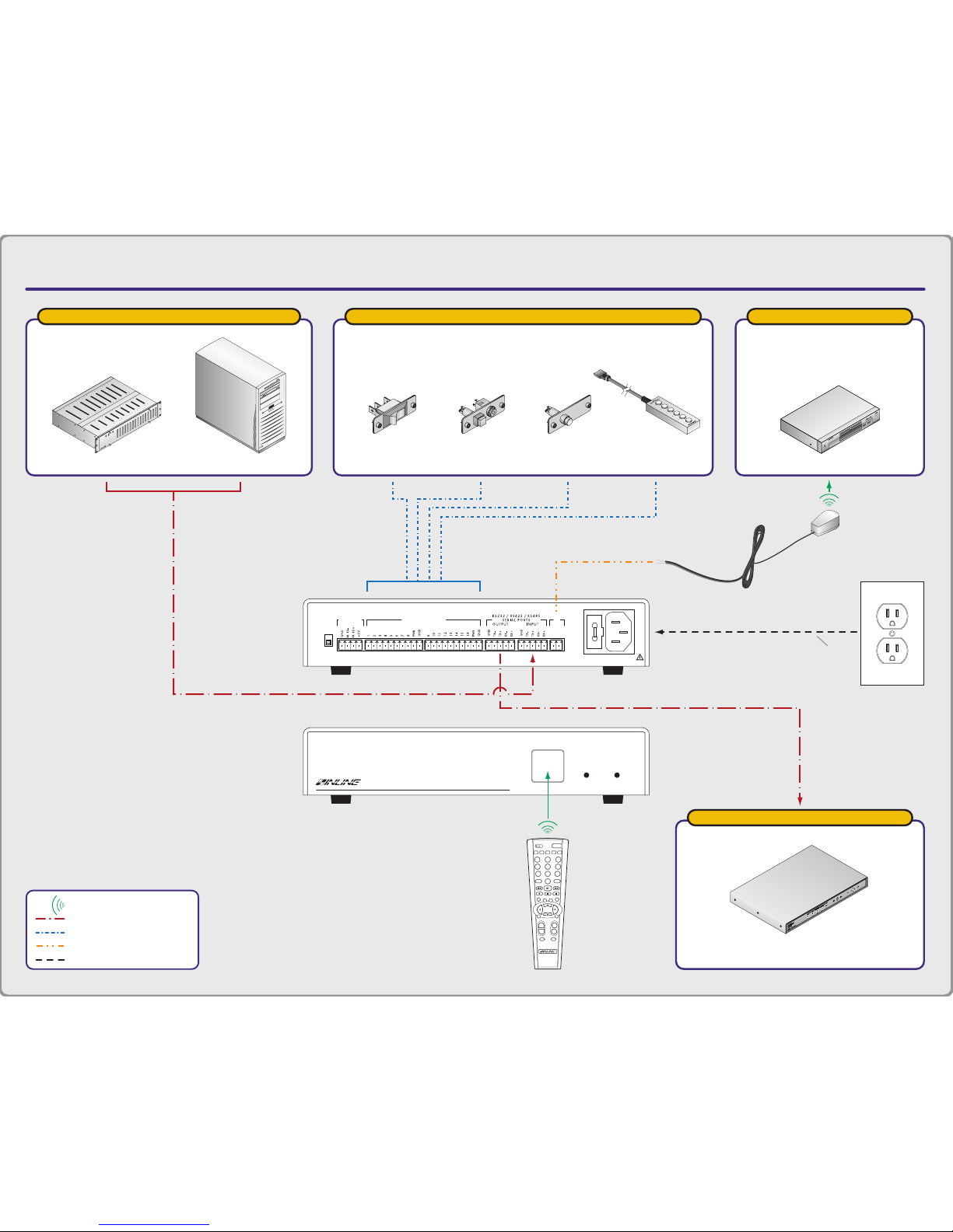
APPLICATION DIAGRAM A
CTL101 CONTROL INTERFACE
CH VOL
ENTERMENU
BLANK MUTE
FREEZE
INPUT RECALL
ENTER
ENTPIP
AUDIO
POWER
1 2 3
4 5
8 97
0
6
S
MATRIXSWITCHER
VIDEO
SCALER
+–+
–
MENU OK
REMOTE
CTL101
Control Interface
POWER
TECHNICAL SUPPORT:
EXT
INT
SENSOR
MODE
(800) 882-7117
(714) 921-4100
www.inlineinc.com
MADE IN U.S.A
IR SENSOR
INPUT
CONTACT CLOSURE
IR
OUT
+ –
FUSE: 0.250A; 250V; TIME DELAY
90-260VAC; 0.05A; 47-63Hz
serially controlled
IN1404 Video / RGB Video Scaler
with RS-232 Serial Control Port
contact closure sources
IN3590
Wired Remote
IN9360 Module
With Switch
SwitchIN9471 Module
With Double
Throw Switch
serial control sources
Control System
PC
ir controlled
DVD Player with IR Control
A/C
Power
Source
CTL101
Back View
CTL101
Front View
CTL120
Infrared Remote
= IR Signal
= Serial Control
= Contact Closure
= Hard-Wired IR Signal
= Power
CTL130
IR Emitter

APPLICATION DIAGRAM B:
IR to Serial Command Conversion
CTL101 CONTROL INTERFACE
= IR Signal
= Serial Control
= Power
TECHNICAL SUPPORT:
EXT
INT
SENSOR
MODE
(800) 882-7117
(714) 921-4100
www.inlineinc.com
MADE IN U.S.A
IR SENSOR
INPUT
CONTACT CLOSURE
IR
OUT
+ –
FUSE: 0.250A; 250V; TIME DELAY
90-260VAC; 0.05A; 47-63Hz
CTL101
Back View
CH VOL
ENTERMENU
BLANK MUTE
FREEZE
INPUT RECALL
ENTER
ENTPIP
AUDIO
POWER
1 2 3
4 5
8 97
0
6
S
MATRIXSWITCHER
VIDEO
SCALER
+–+
–
MENU OK
REMOTE
CTL101
Control Interface
POWER
CTL101
Front View
CTL120
Infrared Remote
RS232 or RS422 or RS485
serially controlled devices
IN1404 Video / RGB Video Scaler
with RS-232 Serial Control Port
IN31608–6 Presentation Switcher
with RS-232 Serial Control Port
A/C
Power
Source

APPLICATION DIAGRAM C:
Contact Closure to Serial Command Conversion
CTL101 CONTROL INTERFACE
TECHNICAL SUPPORT:
EXT
INT
SENSOR
MODE
(800) 882-7117
(714) 921-4100
www.inlineinc.com
MADE IN U.S.A
IR SENSOR
INPUT
CONTACT CLOSURE
IR
OUT
+ –
FUSE: 0.250A; 250V; TIME DELAY
90-260VAC; 0.05A; 47-63Hz
CTL101
Back View
RS232 or RS422 or RS485
contact closure sources
IN3590
Wired Remote
IN9360 Module
With Switch
SwitchIN9471 Module
With Double
Throw Switch
= Serial Control
= Contact Closure
= Power
serially controlled devices
IN1404 Video / RGB Video Scaler
with RS-232 Serial Control Port
IN31608–6 Presentation Switcher
with RS-232 Serial Control Port
A/C
Power
Source

APPLICATION DIAGRAM D:
Remote IR Sensor / IR Repeating
CTL101 CONTROL INTERFACE
TECHNICAL SUPPORT:
EXT
INT
SENSOR
MODE
(800) 882-7117
(714) 921-4100
www.inlineinc.com
MADE IN U.S.A
IR SENSOR
INPUT
CONTACT CLOSURE
IR
OUT
+ –
FUSE: 0.250A; 250V; TIME DELAY
90-260VAC; 0.05A; 47-63Hz
CTL101 — Back View
CTL131 Remote IR
Sensor Module
4 Conductor
20 AWG Cable
= IR Signal
= 4 Conductor 20 AWG
= Hard-Wired IR Signal
= Power
ir controlled devices
DVD Player with IR Control
VHS Player with IR Control
CH VOL
ENTERMENU
BLANK MUTE
FREEZE
INPUT RECALL
ENTER
ENTPIP
AUDIO
POWER
1 2 3
4 5
8 97
0
6
S
MATRIXSWITCHER
VIDEO
SCALER
+–+
–
MENU OK
CTL120
Infrared Remote
A/C
Power
Source
CTL130
IR Emitter
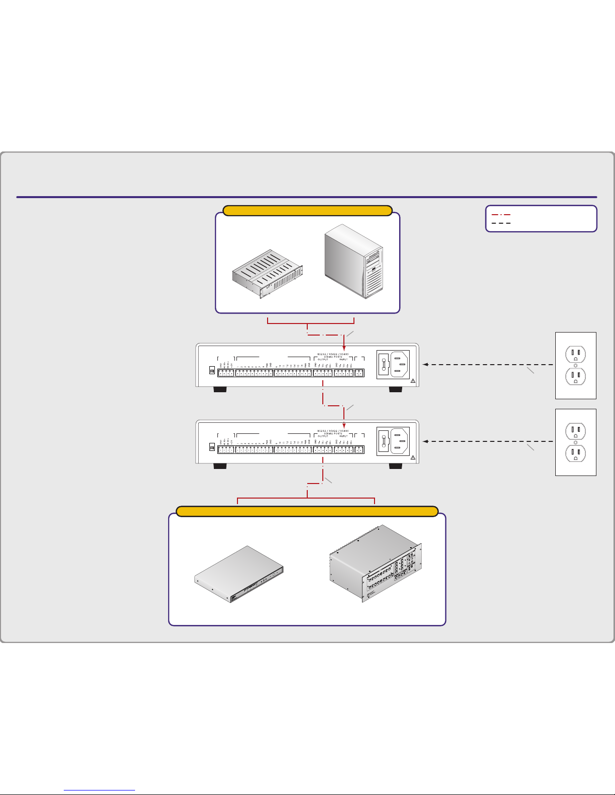
APPLICATION DIAGRAM E:
Serial Command Conversion / Long Distance Transmission
CTL101 CONTROL INTERFACE
TECHNICAL SUPPORT:
EXT
INT
SENSOR
MODE
(800) 882-7117
(714) 921-4100
www.inlineinc.com
MADE IN U.S.A
IR SENSOR
INPUT
CONTACT CLOSURE
IR
OUT
+ –
FUSE: 0.250A; 250V; TIME DELAY
90-260VAC; 0.05A; 47-63Hz
CTL101
Back View
TECHNICAL SUPPORT:
EXT
INT
SENSOR
MODE
(800) 882-7117
(714) 921-4100
www.inlineinc.com
MADE IN U.S.A
IR SENSOR
INPUT
CONTACT CLOSURE
IR
OUT
+ –
FUSE: 0.250A; 250V; TIME DELAY
90-260VAC; 0.05A; 47-63Hz
CTL101
Back View
= Serial Control
= Power
serial control sources
Control System
PC
RS232
RS485 up to 1000'
RS232
A/C
Power
Source
A/C
Power
Source
serially controlled devices
IN1404 Video / RGB Video Scaler
with RS-232 Serial Control Port
IN31608–6 Presentation Switcher
with RS-232 Serial Control Port

12
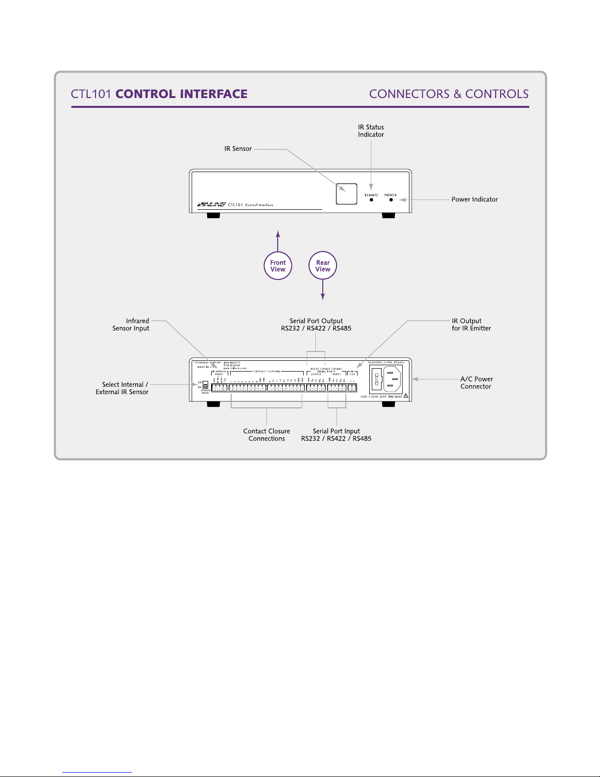
CTL101 Connectors and Controls
FRONT PANEL INDICATORS
The Remote and Power LED’s, and the IR receiver sensor are located on the front panel of the
CTL101 (see the diagram on the following page). The Power LED will illuminate as soon as
power is applied to the unit (the CTL101 has no ON/OFF switch). The Remote LED will
illuminate whenever the interface receives an infrared signal from any IR remote control.
REAR PANEL CONNECTORS AND CONTROLS
All connectors and controls are located on the back of the unit, and the dipswitches are located on
the bottom (see the Dipswitch Bank Tables on page 14).
Sensor Mode - is located on the left rear of the CTL101. This switch allows users to toggle
between the unit’s internal IR sensor and the remote sensor. When the switch is in the INT
position (down), the unit’s internal IR sensor is active (factory default). In the EXT position
(up), the remote sensor (attached to the IR Sensor Input) is active.
IR Sensor Input - is a 4-pin captive screw terminal that connects directly to the CTL131DB /
CTL131DW IR Remote Sensor (see Application Diagram D on page 10).
Contact Closure Ports - allow users to connect up to 16 devices with contact closure capability
(see Application Diagram C on page 9).
RS-232 / RS-422 / RS-485 Serial Ports - The Output Port connects directly to the IN1402 /
IN1403 / IN1404 Video Scaler, IN3600 Series Switcher or IN31608 Matrix or any other device
that accepts ASCII command strings. The Input Port connects directly to the computer
workstation (see Application Diagram E on page 11).
IR Out - connects to the CTL130 IR Emitter via a 2-pin captive screw terminal (see Application
Diagram D on page 10).
Fuse - 0.25A, time delay
Power - Universal power: 90 - 260 VAC, 47 - 63 Hz.
CTL101 Operation Manual - V1.3 03/22/02 ©2002 - INLINE, Inc.
13
DIPSWITCH SETTINGS
On the bottom of the unit are two sets of dipswitches. Dipswitch Bank #1 is used to configure
the serial ports to operate as an RS-232, or RS-422 / RS-485 physical interface. Dipswitch Bank
#2 is used to isolate the contact closure ports and to configure the CTL101 to the default baud
rate (9600). The factory default and specialized dipswitch settings are listed below:
Factory Default Settings:
Dipswitch Bank #1:
Dipswitches 1, 2, 3, 4, 5 & 6: All in "0" position
Input Port Serial Mode: RS-232, no termination
Output Port Serial Mode: RS-232, no termination
©2002 - INLINE, Inc. CTL101 Operation Manual - V1.3 03/22/02
14
Dipswitch Bank #2:
Dipswitches 1, 2, 3, 4: 1 & 2 in "1" position
3 & 4 in "0" position
Contact Closure Port +5V Enable / Disable: Enabled (CTL101 provides power)
Contact Closure Port Ground Enabled / Disabled: Enabled (CTL101 provides power)
Baud Rate Override (Cycle power off / on to
activate new setting): Normal
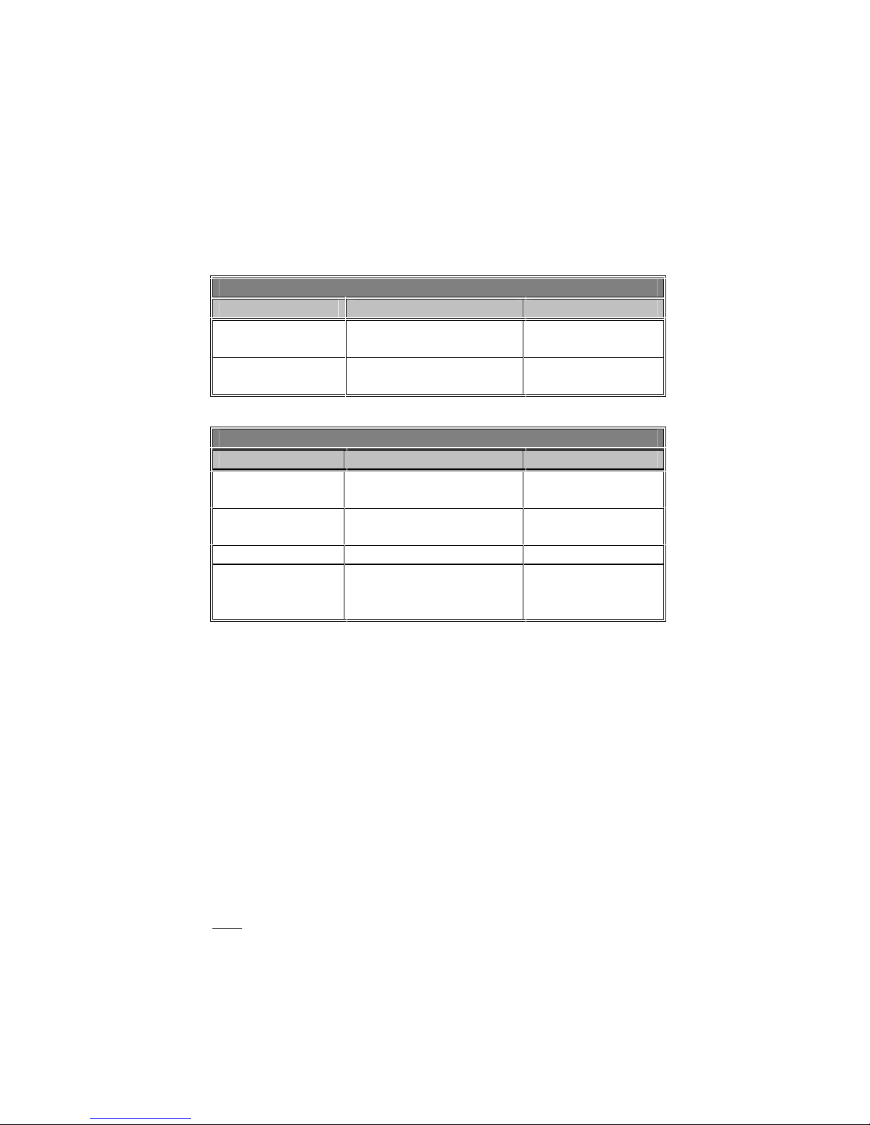
Dipswitch Bank #1
Dipswitch Function Setting
1, 2 & 3
4, 5 & 6
Input Port Serial Mode
Output Port Serial Mode
1 RS-485 / RS-422
0 RS-232*
1 RS-485 / RS-422
0 RS-232*
Dipswitch Bank #2
Dipswitch Function Setting
1
2
Contact Closure Port
+5V Enable / Disable
Contact Closure Port
Ground Enable / Disable
1 Enable*
0 Disable
1 Enable*
0 Disable
3 Reserved
4
Baud Rate Override
(Cycle power off / on to
activate new setting)
1 9600 Baud
Group 1
0 Normal*
* Factory Default
DIPSWITCH BANK #1
Dipswitches 1, 2 and 3 control the Input Port, while 4, 5 and 6 control the Output Port. The Input
/ Output port will operate in RS-232 mode when all six dipswitches are in the "0" position
(default), and in the RS-422 / RS-485 mode when all six dipswitches are in the "1" position.
Switching pairs 2 & 3 and 5 & 6 will terminate the receive & transmit signals (respectively) at
their ports.
DIPSWITCH BANK #2
In most cases, the contact closure ports use internal power from the CTL101 to sense changes
(switches 1 & 2 are enabled). Users can completely isolate the remote contacts & wiring from
the CTL101 by incorporating an external +5 volt power supply into the system (see the CTL101
Contact Closure Inputs Diagrams on page 6). In such applications, the internal power supply of
the CTL101 must
When dipswitch #4 is in the "0" position (normal), the CTL101 automatically recalls the last
configuration at power-up. Users can override the last settings and power-up the unit at factory
default (9600 baud) by setting the switch to the "1" position (override). Note that the factory
default also sets the Code End / Menu Call character to an asterisk (*).
be disconnected from the contact closure ports by disabling dipswitches 1 & 2.
CTL101 Operation Manual - V1.3 03/22/02 ©2002 - INLINE, Inc.

15
Serial Port Set-Up
Preprogrammed command functions can be sent via the RS-232 / RS-422 / RS-485 serial output
port. The CTL101 accepts serial commands from a control system, computer serial port or any
other device capable of sending out serial ASCII commands at compatible baud rates, and relays
the commands to the video equipment via the output port.
RS-232, RS-422 & RS-485 FORMATS
RS-232, RS-422 and RS-485 formats are physical interface standards for serial communication.
RS-232 is a full duplex operation that is typically used for short distances (up to 25’). RS-232
full duplex is the most common format and is limited to point-to-point applications (i.e. one
computer, one piece of equipment). It is not designed for the simultaneous usage of several units
or for sending serial information over very long cable lengths.
RS-422 and RS-485 formats can operate in both full and half duplex modes. In half duplex
mode, only one unit can transmit information at any given time. Therefore, other units in the
system will not respond until the initial transmission is concluded, and only one unit can respond
at any given time. Half duplex mode is preferred for applications involving multiple devices and
/ or communication along fewer lines.
Note: Configuring the CTL101 for full or half duplex serial port operation is discussed in the
Serial Port Control Section on pages 20 - 22.
Both RS-422 and RS-485 formats are designed for longer cable runs (actual lengths depend on
cable grade, capacitance and a number of other variables). RS-485 is recommended when
operating multiple units on a single line.
Reflections will sometimes occur when signals are sent over long cable runs
(in the RS-422 / RS-485 mode). If a system incorporates several units and /
or long control cable runs (while operating in full duplex mode), users can
minimize reflections by setting dipswitches 2 & 3 and /or 5 & 6 to the "1"
position (on the CTL101) and / or by engaging the termination resistors on
the units located at opposite ends of the control cable (see diagram on page
5). For half duplex applications, engage switch 2 and / or 5 only.
COMMUNICATION PROTOCOL
1 start bit 1 stop bit
8 data bits no flow control (factory default setting)
no parity check 9600 baud (factory default setting)
BAUD RATE SELECTION
The CTL101 has a factory default baud rate of 9600 bps and can communicate at baud rates from
1200 up to 115,200.
Note: The baud rate of the computer / A/V equipment must match the baud rate selected on the
CTL101 (both the input and output port are set to the same baud rate).
If communication is lost, use the default switch on the bottom of the
CTL101 to reset the unit to factory default (9600 baud).
©2002 - INLINE, Inc. CTL101 Operation Manual - V1.3 03/22/02

16
TERMINAL EMULATION PARAMETERS*
In order for the workstation to communicate with the CTL101, the terminal emulation program
parameters must be set as follows:
Enabled:
VT100 Terminal Emulation
Echo Typed Characters Locally (sending)
Wrap Lines that Exceed the Terminal Width (receiving)
Disabled:
* Software comes standard with the Windows™ Package.
By default, the CTL101 is set up to accommodate most common terminal emulation programs. If
the unit is not communicating properly (i.e. unwanted text / m essages appear on the screen, double
spacing occurs between menu choices, menu selections are followed by "error" responses, etc.),
set the parameters to full duplex, no delimiter pause and no flow control, then check the emulation
program set-up. Refer to the Serial Port Control Section on pages 20 - 22 for more details.
XON / XOFF Control
Hardware Flow Control
Echo Received Characters
CTL101 Set-Up Menu
Power-up the CTL101 and open the systems terminal em ulation program. Type in an asterisk (*)
to bring up the setup menu. With Firmware Revisions 1.2, you may change the asterisk to any
character you choose.
Note: Whatever character you select, you may not use it in any
The Main Setup Menu will look like this:
*CTL101 Main Menu - please enter selection.
1. Switch codes.
2. Infrared codes.
3. Serial Port.
4. Delimiter pause.
5. Set Code End character.
5. Self Test.
6. Exit.
CONTROL CODES FOR CONTACT CLOSURE
If the application involves control codes for contact closure, type "1" in the main menu followed
by ENTER.
A new feature includes Hexadecimal code entry (HEX format). HEX format codes must be
entered in pairs (even number of entries). Also, in ASCII format, Carriage Return (Ctrl M) and
Line Feed (Ctrl J) may now be entered as part of the code string (they were previously ignored).
HEX format code entry must be in capital letters "0-F" (Version 1.1 or later in self test).
command string.
CTL101 Operation Manual - V1.3 03/22/02 ©2002 - INLINE, Inc.

17
The next series of menus will look like this:
Switch Codes - enter selection.
1. Clear All switch codes.
2. Switch closure code. (ASCII format)
3. Switch open code. (ASCII format)
4. Switch closure code. (HEX format)
5. Switch open code. (HEX format)
6. Exit.
Select 2, 3, 4, or 5.
Enter Switch # (1 - 16).
Select the switch #.
**New:
Enter selection.
1. Enter code.
2. Delete code.
3. Display current.
4. Exit.
Select "1".
Begin entering Command codes
- End with a Code End character (Default = asterisk *)
- Backspaces will be ignored.
1. Clear All Switch Codes - allows users to delete all pre-existing contact closure codes
simultaneously.
2 & 4. Switch Closure Code - will prompt users to select a switch number (1-16). Upon
selection of the appropriate switch number, a message will appear indicating whether the switch
code "Exists" or is "New". Users can now establish command strings for contact closure states,
delete commands or display the current command string.
3 & 5. Switch Open Code - same as Switch Closure Code but for contact opening.
6. Exit - will always return users to the previous menu.
Contact closure command code strings can consist of (up to) 120
characters. A "Code Area is Full" message will appear after 120
characters have been entered.
Note: If Delimiter Pause is selected, the CTL101 will pause for a response end delimiter or a
one second timeout between commands in a string, allowing the controlled equipment time to
process each command. See the Delimiter Pause Section on pages 21-22 for more details.
©2002 - INLINE, Inc. CTL101 Operation Manual - V1.3 03/22/02

18
INFRARED CODES
If the application involves infrared codes, type "2"in the main menu followed by ENTER. The
next series of menus will look like this:
IR Codes - enter selection.
1. Clear All codes in user programmable group.
2. Set/Change/Clear/Display a code. (ASCII format)
3. Set/Change/Clear/Display a code. (HEX format)
4. Select current code group.
5. Exit.
Select 2, or 3.
**Press remote button.
**Press again - Verify.
**New:
Enter selection.
1. Enter code.
2. Delete code.
3. Display current.
4. Exit.
Select "1".
Enter selection.
1. Remote delay ON - for Single push.
2. Remote delay OFF - for Continuous push.
Begin entering Command codes
- End with a Code End character (Default = asterisk *)
- Backspaces will be ignored.
1. Clear All Codes in User Programmable Group - allows users to erase all group #3
command codes (provided that group #3 is enabled).
The CTL101 features three groups of command codes associated with IR signals. The first
two groups are programmed at the factory with the serial command codes for INLINE video
scalers, switchers and matrices, and cannot be changed. The third group allows users to
program their own set of command strings. Once established, the unit will always power up
in the last group selected.
Group #1 Command Codes - allow users to run a single INLINE unit by using the same
delimiters (the same beginning and end [ ] brackets).
Group #2 Command Codes - have different delimiters allowing the simultaneous usage of
several pieces of INLINE equipment (i.e. switcher { }, matrix ( ), scaler [ ]).
Group #3 Command Codes - are completely user programmable and are capable of
directing several pieces of equipment simultaneously.
Note: When programming Group 3 for the first time or reprogramming the entire group, Group
3 must be enabled
, and all codes must be cleared before you begin.
CTL101 Operation Manual - V1.3 03/22/02 ©2002 - INLINE, Inc.

19
2 & 3. Set / Change / Clear / Display a Code - will prompt users to push an IR remote control
button to be associated with the operations. Another prompt will be displayed to verify the
selection. If the IR signal is acceptable, the unit will indicate if it is a "New" or "Existing"
command code.
A new feature includes Hexadecimal code entry (HEX format). HEX format codes must be
entered in pairs (even number of entries). Also, in ASCII format, Carriage Return (Ctrl M) and
Line Feed (Ctrl J) may now be entered as part of the code string (they were previously ignored).
HEX format code entry must be in capital letters "0-F" (Version 1.01 or later in self test).
Select one of the following:
1. Enter Code - If selected, two menus will be displayed:
First Menu:
Enter Selection.
1. Remote Delay ON - for Single push
2. Remote Delay OFF - for Continuous push
Users are now prompted to program the CTL101 for either single push operation (which
repeats the code no faster than 2 times per second), or for continuous operation (to repeat
the code 20 times per second while the button is pushed). Single push modes are utilized
for most operations, while continuous push modes are primarily used for such functions as
volume regulation.
Second Menu:
Begin entering Command codes
- End with a Code End character (Default = asterisk *)
- Backspaces will be ignored.
After the remote has been configured, the unit will automatically begin the code entry mode
(which is the same as contact closure entry). The group has the capacity to store up to 72
individual remote command strings.
2. Delete Code - deletes the previously programmed command.
3. Display Current - shows the current command status.
4. Select Current Code Group - allows users to enable one of the three groups.
©2002 - INLINE, Inc. CTL101 Operation Manual - V1.3 03/22/02

20
REPROGRAMMING OR USING A DIFFERENT IR REMOTE CONTROL
The CTL120 IR Remote is pre-programmed at the factory and will readily support most
applications. However, If operators wish to use their own remote, or if the CTL120 commands
interfere / are incompatible with components in the system, the existing command codes may
have to be changed. Recommended manufacturer’s command codes include Sony (default),
JVC, Panasonic, Pioneer and RCA/Proscan. A complete list of manufacturers, components and
code numbers is provided in the CTL120 Operation Manual.
Note: Reprogramming of the CTL120 Remote should only be done by qualified technicians.
When first setting up IR commands with a new manufacturer / component remote control code
format, a "Signal Error" may result. If this happens, try again. If the "Signal Error" message
occurs three times, then the manufacturer / component code is incompatible with the CTL101.
Try another manufacturer’s code format (a list of available codes is provided in the back of the
CTL120 Operations Manual).
SERIAL PORT CONTROL
If SERIAL PORT is selected in the main menu, type "3" followed by ENTER. The next series of
menus will look like this:
Select Input Port option.
1. Baud Rate.
2. Flow Control.
3. Full or Half Duplex ports.
4. Exit.
Select "1".
Select Baud Rate.
1. 1,200
2. 2,400
3. 4,800
4. 9,600
5. 19,200
6. 38,400
7. 57,600
8. 115,200
9. Display current.
10. Exit.
1. Baud Rate - allows users to change the baud rate. The new setting will become the default baud rate.
The terminal computer baud rate must now be changed to communicate with (match) the CTL101.
Note: Change the A/V equipment baud rates first
baud rate last
Select "2".
.
Select Input Port flow control.
1. Enable XON/XOFF.
2. Disable XON/XOFF.
3. Display current.
4. Exit.
, the CTL101 baud rate second, and the computer
CTL101 Operation Manual - V1.3 03/22/02 ©2002 - INLINE, Inc.

21
2. Flow Control - The Input Serial Port (host computer) can receive XON / XOFF flow control from
the CTL101. This is beneficial when the host computer is controlling the video equipment
simultaneously with a contact closure and / or IR signal.
If a contact change or an IR signal is sensed, the CTL101 will send an XOFF command to the
computer (once a delimiter is received from the computer going to the equipment, or a one second
timeout). This allows the computer to stop transmitting command messages without overflowing
the 32 byte FIFO in the CTL101 receive buffer. The CTL101 will trap the response message
from the video equipment in response to the last command from the host computer. At this time
the CTL101 will start sending its programmed command string to the video equipment. After the
CTL101 has sent its command string, an XON will be sent to the host computer indicating it can
resume communication with the video equipment. At this time, the trapped response from the last
host command will be sent to the host computer to verify that the last command was processed.
Note: This feature must be used with the delimiter pause established, otherwise the CTL101 has no
way of knowing when the host computer has ended a command and the video equipment has ended its
response.
Select "3".
Select Full or Half duplex ports.
1. Both ports Full Duplex (Default).
2. Input port Full Duplex & Output port Half Duplex.
3. Input port Half Duplex & Output port Full Duplex.
4. Both ports Half Duplex.
5. Display current.
6. Exit.
3. Full or Half Duplex Ports - For RS-232 operation, full duplex communication is selected. In RS422 / RS-485, either full or half duplex communication can be selected.
In half duplex mode and computer control, the driver turns on as each character is transmitted,
and the character is sent without any flow control provided by the CTL101. To prevent
contention, the controlled equipment and the host computer system must provide some means of
flow control. Typically, the host computer would send a command, shut its driver off, and wait
for a response from the controlled equipment before sending the next command. The CTL101
acts as a relay unit between the computer and controlled equipment.
When the CTL101 sends commands in half duplex mode for IR remote control or contact
switches, it automatically activates its driver for each command character transmitted. The
CTL101 uses the end delimiter responses to determine when it can send the next command in a
string. If no end delimiters are detected within one second, it will automatically send the next
command.
DELIMITER PAUSE
If DELIMITER PAUSE is selected, type "4" followed by ENTER. The next series of menus will look
like this.
Select Delimiter Pause.
1. Don’t wait for response.
2. Wait for response between commands.
3. Display current.
4. Exit.
©2002 - INLINE, Inc. CTL101 Operation Manual - V1.3 03/22/02
22
1. Don’t Wait For Response - allows the CTL101 to deliver a command without receiving an end
delimiter from the controlled equipment. In most instances this mode is used because it decreases the
CTL101 response time (it does not have to wait for a response before the next command [button push]
can be issued).
All commands sent to INLINE units must contain a leading code, the command code, and an
ending code. Each unit can be set to recognize several sets of leading and end codes (delimiters):
brackets [ ], parentheses ( ), braces{ }, slashes \ /, a less and greater than sign < > and signs !#.
The factory default serial delimiters are [ ].
A complete command consists of:
[ The leading code
CH3 The command code.
] The ending code
Example: [CH3] sets the unit to select channel 3.
2. Wait For Response Between Commands (ASCII format only) - allows the CTL101 to wait for
equipment responses while executing a command string. The CTL101 looks for an end delimiter
from the host computer commands (or 100 millisecond timeout) and a response from the controlled
equipment commands (or 1 second timeout) before initiating a contact or IR command string.
For example, users could program the following commands to be issued with one IR remote
button push: [CH1][CH2][CH3][CH4]. With the pause engaged, the CTL101 would send out
the initial command [CH1], wait for a response (with an end delimiter) from the controlled
equipment, send the next command [CH2], wait again, etc. In each case, the CTL101 would wait
for a response before issuing the next command.
Avoid setting the delimiter pause unless a string of commands is involved.
Doing so will extend the time between infrared remote button responses.
3. Display Current - shows the current delimiter pause status.
SET CODE END CHARACTER
If an asterisk (*) is required in the command code, then you may choose another character to
evoke the Main Menu and to terminate the command code entry. Enter "5" at the Main Menu,
followed by Enter.
Type in a Code End / Menu Call character (Default = * asterisk).
- Note: This character will be Case Sensitive.
Note: If you forget this Code End / Menu Call character, reset the unit to default (Switch
Bank #2, Switch #4) to set the Code End / Menu Call character to an asterisk (*). You
may then set up another character in place of the asterisk (*). Remember to turn off the
default switch when you are finished.
CTL101 Operation Manual - V1.3 03/22/02 ©2002 - INLINE, Inc.

23
SELF-TEST
If SELF-TEST is selected, the next series of menus will look like this.
Test Results - Rev. 1.2
SRAM...........(PASS)
Flash..........(PASS)
RHost Serial....(PASS)
Inline Serial..(PASS)
Press button on remote.
**Press again - Verify.
IR Signal......(PASS)
Switch 1 to 8..(PASS)
Switch 9 to 16.(PASS)
Remove test cable from switches (10 second timeout).
Switch 1 to 8..(PASS)
Switch 9 to 16.(PASS)
As the name implies, the unit conducts a quick series of tests to make sure that the major
functions / circuits are working properly. The test is primarily designed for factory use,
however, in the event that major problems should occur, the customer can use it to determine
if a problem is associated with the CTL101 operation. The menu indicates the status of the
unit as the system runs a self-check. All functions (SRAM, static memory, Flash, etc.) are
tested and the CTL101 indicates whether or not the unit passed or failed. The serial output
port must be disconnected and both dipswitch banks must be set to default.
If problems occur, running the self-test before calling INLINE Technical Services will allow
technicians to better assist users with problems.
Note: The contact closure test requires a test connector. The first part of the switch test verifies
that all contacts are connected to ground (closed). The second part verifies that all contacts are
open.
©2002 - INLINE, Inc. CTL101 Operation Manual - V1.3 03/22/02

24
Specifications
CTL101 Control Interface
Control Ports:
IR Remote Sensor Port 4-Pin Captive Screw Terminal
IR Emitter Port 2-Pin Captive Screw Terminal
Contact Closure Port
Contact Closure Signals Latching or Momentary (100 mSec minimum pulse time)
Contact Closure Power +5 VDC / 7 mA per contact
Serial Input Port 5-Pin Captive Screw Terminal
Serial Output Port 5-Pin Captive Screw Terminal
Serial Interface Formats RS-232 (default) / RS-422 / RS-485
Default Serial Protocol 9600 bps, 1 start bit, 8 data bits, no parity, 1 stop bit, no flow control
Flow Control XON / XOFF or None
Serial Port Baud Rates 1200 bps to 115,200 bps
General
Command Capacity
IR Sensor
Operational Distance: 30 feet / 10 meters Angle: 30 degrees
(operational distance may be sacrificed at this angle)
Remote Sensor Distance from CTL101: 1,000 feet
Power Supply 90-260 VAC; 47-63 Hz; 0.05 Amps (Internal Universal)
Product Weight 1 lb. / 0.45 kg
Shipping Weight 3 lbs. / 1.5 kg
Dimensions 1.65" x 8.5" x 6" / 4.2cm x 21.6cm x 15.2cm
Regulatory Compliance
EMI & Safety
FCC class A; CE: EN50022 (1987), EN50081-1 (1991),
Parts Included
(1) CTL101: Control Interface
(1) IN9230: IEC Power Cable, 6’ long (USA only)
(1) IN9339: Adjustment Tool with Technician’s Blade
(1) 4-Pin Remote IR Sensor Connector with Screw Terminals
(2) 5-Pin Serial Port Connectors with Screw Terminals
(2) 10-Pin Contact Closure Connectors with Screw Terminals
(1) Operation Manual
(2) 10-Pin Captive Screw Terminals
(16) Control Ports / (2) Power / (2) Ground
72 IR Commands
16 Contact Closures
120 Characters per Command String
UL 1950, CAN/CSA-22.2 No. 950 3rd Ed.
EN50082-1 (1992 & 1994), EN60950-92
CTL101 Operation Manual - V1.3 03/22/02 ©2002 - INLINE, Inc.
25
Optional Accessories
IR Accessories
CTL120-1: IR Remote Control
CTL120-2: IR Remote Control with Overlay for IN1402 / IN1403 / IN1404 Video Scalers,
IN3600 Series Switchers and the IN31608 Matrix Switcher
CTL130: IR Emitter
CTL131DB: Remote IR Sensor - Double Size A/V Connector Module - Black
CTL131DW: Remote IR Sensor - Double Size A/V Connector Module - White
Mounting Hardware
IN9080: Rack Shelf - For mounting the CTL101 in a standard 19" equipment rack
IN9088B: Half-Rack Blank Plate - Fills space when rack mounting one CTL101
Troubleshooting
Problem: The power cord is plugged in, but the front panel POWER LED is dark.
Solution 1: Make sure that the IN9230 IEC power cable is securely plugged into the unit and t he
A/C source.
Solution 2: Make sure the A/C source is live.
Solution 3: The CTL101 contains a 0.25A time delay fuse. To change the fuse, first, disconnect
the power cord. Slide out the fuse holder (located on the rear panel to the left of the IEC cable
receptacle) using the IN9339 alignment tool (included).
Problem: There is no response from the CTL120 Remote and the remote LED on the
front of the CTL101 does not illuminate.
Solution 1: Make sure that the CTL120 is positioned at an angle that is no more that 30 degrees
from the CTL130 IR Sensor.
Solution 2: Make sure that the CTL120 is no farther than 30 feet from the IR Sensor.
Solution 3: Make sure that the IR sensor mode switch is in the correct position.
Solution 4: The batteries in the CTL120 may be old / weak. Replace them if necessary.
For best results, position the emitters and sensors in direct line with each
other whenever possible. The exception to the rule is when the CTL130 IR
emitter is involved in the application. Do not place the CTL101 in a location where the unit’s sensor window will detect the emitter signal, or in an
area in which the signal could feed back into the unit. This condition is evident whenever a remote control command is issued and the remote LED on
the CTL101 remains "ON" even after the remote control button is released.
Problem: While setting up the IR remote control for a new manufacturer / component for
the first time, a "Signal Error" message appears on the screen.
Solution 1: The "Signal Error" may result from the CTL101 adjusting to a new code format. Try
again.
Solution 2: If the "Signal Error" message occurs three times, then the manufacturer / component
is incompatible with the CTL101. Try another manufa cturer’s code format on your remote
control.
©2002 - INLINE, Inc. CTL101 Operation Manual - V1.3 03/22/02

26
Problem: While entering a command code, a "Code Area is Full" message appears on the
screen.
Solution: Command code strings can only consist of (up to) 120 characters. When the message
appears, back up one command and terminate the string by using an asterisk (*).
Problem: Infrared remote commands are responding very slowly.
Solution: Unless a string of commands is involved, avoid setting the DELIMITER PAUSE.
Problem: There is no response from serial commands.
Solution 1: Make sure that the baud rates of the controller and the unit match.
Solution 2: Make sure the controller is configured as eight data bits, one stop bit and no parity.
Solution 3: Make sure that the correct command codes and delimiters are being used.
Solution 4: Make sure that the connector cable is properly inserted into both / all units.
If problems persist, call INLINE Technical Services at (714) 450-1800 for further assistance.
Contact Switch Technical Information
1. Contact current is controlled via a 560-ohm resistor to less than 10 milliamps.
2. A debounce time of 50 milliseconds is built into the software.
3. Optical output isolation is 2,500 VRM’s.
4. The contact closure bank 1 (switches 8 thru 1) are checked first, if no changes are sensed
then bank 2 (switches 16 thru 9) is sampled. If a change is sensed in bank 1 the order of
service is first switch 8 on down to switch 1. If a change is sensed in bank 2 the order of
service is first switch 16 on down to switch 9. Thus the priority of service is always
switch 8 down to switch 1 and then switch 16 down to switch 9.
5. The Contact closure port is interleaved with service of the serial input, serial output, and
infrared ports. Thus only one contact change is serviced between services of the other
ports. This prevents one very active port from locking out service to the other ports.
CTL101 Operation Manual - V1.3 03/22/02 ©2002 - INLINE, Inc.
CONNECTORS & CONTROLS
IN3808 / IN20804 / IN21608 /
IN31208 / IN31608 Matrix Switchers
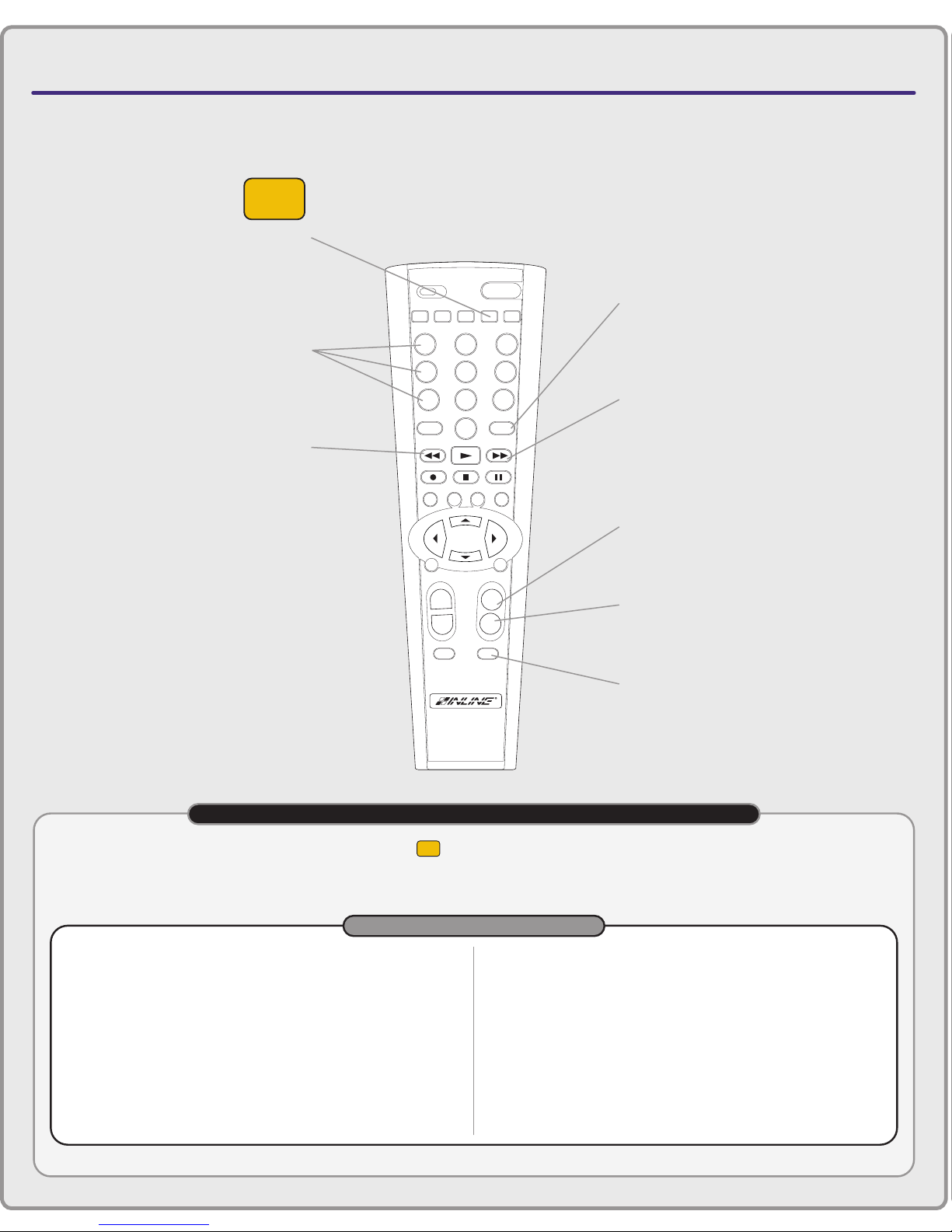
CTL120-2 REMOTE CONTROL
1st BUTTON TO PRESS
CH VOL
ENTERMENU
BLANK MUTE
FREEZE
INPUT RECALL
ENTER
ENTPIP
AUDIO
POWER
123
45
897
0
6
S
MATRIXSWITCHER
VIDEO
SCALER
+
–
+
–
MENU OK
MATRIX
CTL120-2 COMMAND EXAMPLES FOR MATRIX SWITCHERS
COMMAND EXAMPLES
function:
Select Input #3 (Direct Mode only).
steps:
Press the INPUT button, then press numeric buttons 0 and 3.
Press ENTER to execute the command.
function:
Blank the current output or outputs (Direct mode only).
steps:
Press the INPUT button, then press numeric buttons 0 and 0.
Press ENTER to execute the command.
function:
Recall memory configuration #5 (Matrix mode only).
steps:
Press the RECALL button, then press numeric buttons 0 and 5.
Press ENTER to execute the command.
function:
Increase the audio level.
steps:
Press the VOL + button once to increase the volume slightly.
Press and hold VOL + to continuously increase the volume.
function:
Mute the audio signal.
steps:
Press the MUTE button to engage mute.
Press MUTE again to return to previous volume.
Numeric Buttons
Select the desired
input or memory
Enter Button
Executes an input /
memory selection
Recall Button
Recalls a previously stored memory
configuration in Matrix Switching mode.
Press this button first, followed by two
numeric buttons and ENTER
Vol + Button
Increases audio level
Vol – Button
Decreases audio level
Mute Button
Mutes audio signals for
current output / outputs
Matrix Button
Press this button first to set
the CTL120 to control an
INLINE matrix switcher
Input Button
Selects inputs in Direct
Switching mode. Press this
button first, followed by
two numeric buttons and ENTER.
IMPORTANT: You must press the MATRIX button ( ) once to set the CTL120 remote to control INLINE matrix switchers.
Before using the remote control, determine whether your matrix switcher has been set to operate in either Direct mode or
Matrix mode by checking the Switching Mode status lights on the front panel. This will determine whether you use the input
button or the recall button on the remote control to change input / output configurations.
MATRIX
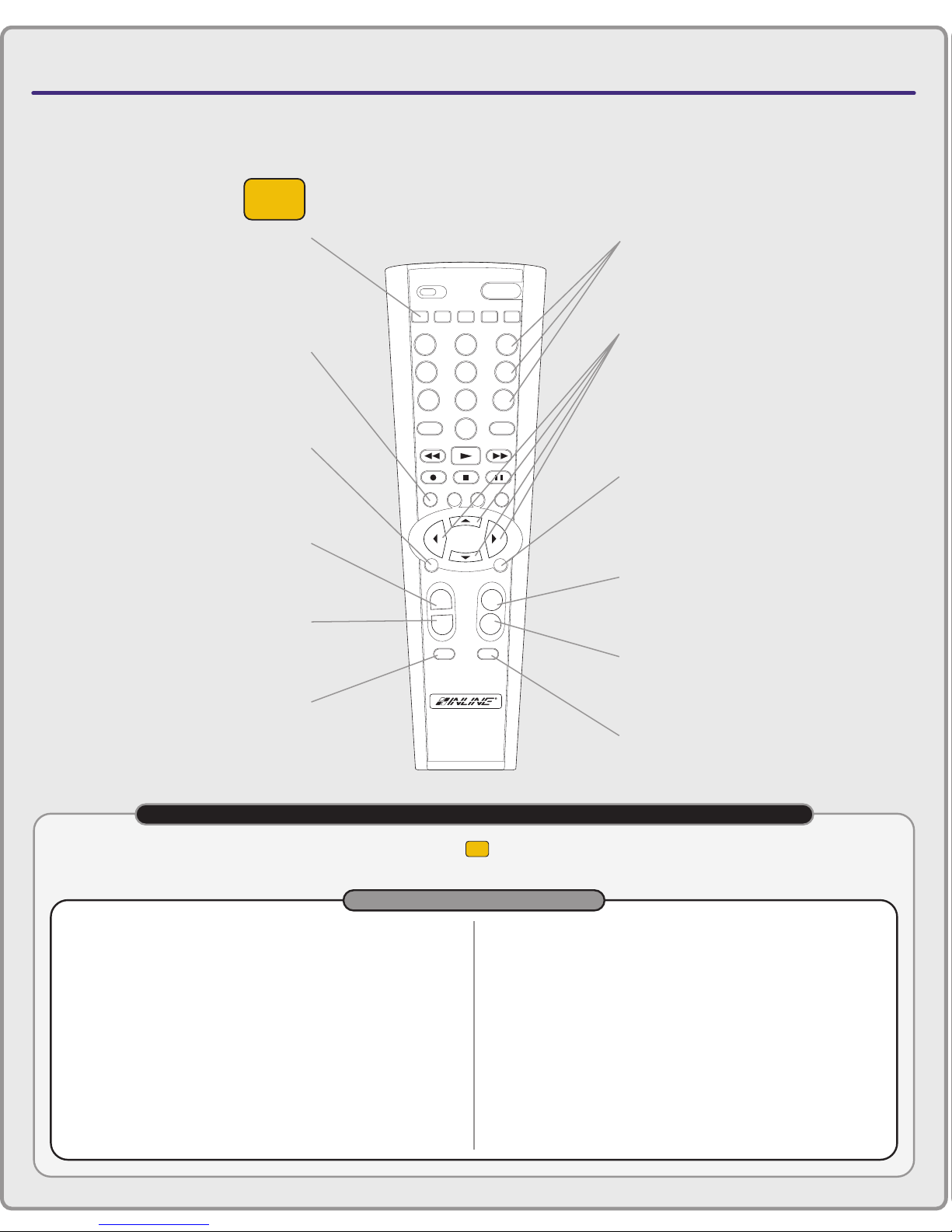
CTL120-2 REMOTE CONTROL
VIDEO
SCALER
1st BUTTON TO PRESS
CONNECTORS & CONTROLS
IN1402 / IN1403 / IN1404 / IN1408 Video Scalers
Video Scaler Button
Press this button first to
set the CTL120 to control
IN1400 Series video scalers
Freeze Button
Enable / Disable
digital still frame
Menu Button
Activates or removes
on–screen menus
CH + Button
Selects the next higher input
CH – Button
Selects the next lower input
897
0
CH VOL
POWER
MATRIXSWITCHER
ENTER
ENTPIP
ENTERMENU
–
AUDIO
6
+
S
VIDEO
SCALER
123
45
INPUT RECALL
FREEZE
MENU OK
+
–
BLANK MUTE
Numeric Buttons
Select desired input
Arrow Buttons
Press the UP ARROW /
DOWN ARROW buttons to navigate
through on–screen menus.
Press LEFT ARROW / RIGHT ARROW
buttons to decrease / increase a setting.
Enter Button
Press to make a menu selection or to
execute a new setting when using
on–screen menus
Vol + Button
Increases audio level
Vol – Button
Decreases audio level
Blank Button
Blanks the video image (black)
Mute Button
Mutes audio signals
CTL120-2 COMMAND EXAMPLES FOR IN1400 SERIES VIDEO SCALERS
VIDEO
SCALER
IMPORTANT: You must press the VIDEO SCALER button ( ) once to set the CTL120 remote to control INLINE
IN1400 Series video scalers.
COMMAND EXAMPLES
function:
steps:
Select Input #3.
Press numeric button 3.
function:
steps:
Engage digital freeze frame
Press the FREEZE button to engage freeze frame.
Press FREEZE again to return to motion video.
function:
steps:
function:
steps:
The scaler is currently set to Input #3. Select Input #4.
Press the CH + button once.
Increase the audio level.
Press the VOL + button once to increase the volume slightly.
Press and hold VOL + to continuously increase the volume.
function:
steps:
Adjust image brightness for the current input.
Press the MENU to activate the on–screen menus.
Press the UP ARROW or DOWN ARROW to move the
selection highlight to Video.
Press ENTER to select the Video menu.
Press ENTER again to select Brightness adjust.
function:
steps:
Mute the audio signal.
Press the MUTE button to engage mute.
Press MUTE again to return to previous volume.
Press the LEFT ARROW or RIGHT ARROW buttons to
decrease / increase the brightness setting.
Press ENTER to accept the new setting.

CONNECTORS & CONTROLS
IN3600 Series Switchers
CTL120-2 REMOTE CONTROL
1st BUTTON TO PRESS
CH VOL
ENTERMENU
BLANK MUTE
FREEZE
INPUT RECALL
ENTER
ENTPIP
AUDIO
POWER
123
45
897
0
6
S
MATRIXSWITCHER
VIDEO
SCALER
+
–
+
–
MENU OK
SWITCHER
CTL120-2 COMMAND EXAMPLES FOR IN3600 SERIES SWITCHERS
COMMAND EXAMPLES
function:
Select Input #3.
steps:
Press numeric button 3.
function:
Blank the video image
steps:
Press numeric button 0.
Numeric Buttons
Press to select the
desired input
Switcher Button
Press this button first to
set the CTL120 to control
IN3600 Series switchers
IMPORTANT: You must press the SWITCHER button ( ) once to set the CTL120 remote to control IN3600 Series switchers.
SWITCHER

30
Warranty
♦
INLINE warrants the equipment it manufactures to be free from defects in materials and
workmanship.
♦
If equipment fails because of such defects and INLINE is notified within three (3) years
from the date of shipment, INLINE will, at its option, repair or replace the equipment at
its plant, provided that the equipment has not been subjected to mechanical, electrical, or
other abuse or modifications.
♦
Equipment that fails under conditions other than those covered will be repaired at the
current price of parts and labor in effect at the time of repair. Such repairs are warranted
for ninety (90) days from the day of re-shipment to the Buyer.
♦
This warranty is in lieu of all other warranties expressed or implied, including
without limitation, any implied warranty or merchantability or fitness for any
particular purpose, all of which are expressly disclaimed.
The information in this manual has been carefully checked and is believed to be accurate.
However, INLINE, Inc. assumes no responsibility for any inaccuracies that may be
contained in this manual. In no event will INLINE, Inc. be liable for direct, indirect,
special, incidental, or consequential damages resulting from any defect or omission in this
manual, even if advised of the possibility of such damages. The technical information
contained herein regarding the CTL101 features and specifications is subject to change
without notice.
Windows is a registered trademark of Microsoft Corporation. All other trademarks and
registered trademarks are the property of their respective companies.
All Rights Reserved © Copyright 2002
INLINE, Inc. ♦ 810 WEST TAFT ♦ ORANGE, CA 92865
©
(800) 882-7117 ♦ (714) 450-1800 ♦ Fax (714) 450-1850
♦ www.inlineinc.com
CTL101 Operation Manual - V1.3 03/22/02 ©2002 - INLINE, Inc.
 Loading...