

Inkel JF46C1900CFN01 Users Manual
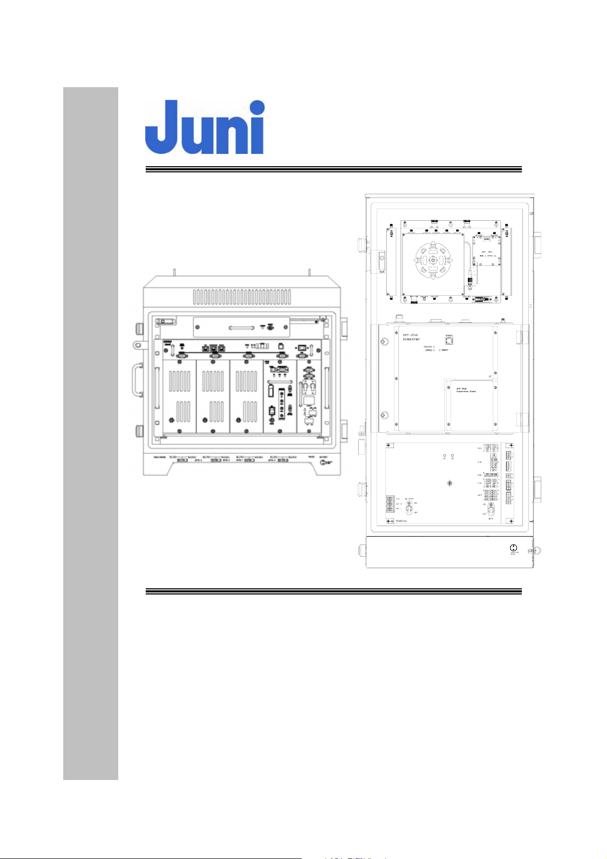
JF-46
Fiber Fed Repeater
350_IN
320_OUT
SPT-JF46
Remote_Optic Module
UL0_IN
DL_OUTUL1_IN
NMS
NMS
UL_1
AC_IN
OPTIC
DL/UL_0
BATTERY(Max 0 .7A)
OPERATIONS MANUAL
Rev 0.1
November 2008
Juni America Inc.

JUNI JF-46-E1900/CFN03
CDMA FIBER FED REPEATER OPERATIONS MANUAL
JUNI AMERICA PROPRIETARY & CONFIDENTIAL
Change History
Version Date Comments
Draft Dec. 29, 2008 Draft Manual
Any changes or modifications not expressly approved by the manufacturer could void the
user’s authority to operate the equipment.
Revision 0.01 J
2
uni America Inc.

JUNI JF-46-E1900/CFN03
CDMA FIBER FED REPEATER OPERATIONS MANUAL
JUNI AMERICA PROPRIETARY & CONFIDENTIAL
Table of Contents
TABLE OF FIGURES.......................................................................................................................................... 5
LIST OF ACRONYMS AND ABBREVIATIONS..............................................................................................7
1. INTRODUCTION........................................................................................................................................ 9
1.1 F
IBER FED REPEATER ............................................................................................................................. 9
1.2 SEARCH WINDOW................................................................................................................................. 10
1.3 T
1.4 FFR
OTAL OPTICAL DELAY (WINDOW SIZE).............................................................................................. 12
COMPONENTS............................................................................................................................... 13
1.5 ADVANTAGES ....................................................................................................................................... 14
1.6 K
1.7 G
EY FEATURES ..................................................................................................................................... 15
ENERAL SAFETY PRECAUTIONS ......................................................................................................... 17
2. SYSTEM DESCRIPTION......................................................................................................................... 19
2.1 FFR
2.2 S
SYSTEM ........................................................................................................................................ 19
IMULCAST OPERATION........................................................................................................................ 19
2.3 DONOR HUB UNIT ................................................................................................................................21
2.3.1 Donor Hub Unit Enclosure and Shelf..............................................................................................21
2.3.2 Wireless Modem Antenna................................................................................................................ 23
2.4 R
EMOTE UNIT ...................................................................................................................................... 24
2.4.1 Remote Unit..................................................................................................................................... 24
2.4.2 Remote Unit Connectors ................................................................................................................. 26
3. INSTALLATION........................................................................................................................................ 27
3.1 T
RANSPORTATION T O THE SITE............................................................................................................. 27
3.2 HANDLING OF THE REPEATER............................................................................................................... 27
3.3 INSTALLATION CONDITIONS ................................................................................................................. 27
3.4 I
NSPECTION BEFORE INSTALLING THE REPEATER.................................................................................. 28
3.5 JF-46 FFR INSTALLATION PROCEDURE ................................................................................................ 28
3.5.1 Tools and Materials......................................................................................................................... 28
3.5.2 Cautions during Installation ........................................................................................................... 29
3.5.3 Optical Fiber Jumper Cable Assembly............................................................................................ 29
3.5.4 Weatherproofing Connectors........................................................................................................... 30
3.5.5 Donor Unit Eye Bolts...................................................................................................................... 31
3.5.6 Donor Unit Standard Wall Mount Guide......................................................................................... 32
3.5.7 Remote Unit Eye Bolts..................................................................................................................... 33
3.5.8 Remote Unit Standard Wall Mount Guide ....................................................................................... 33
3.5.9 AC Cables and Connectors Installation Guide............................................................................... 35
3.5.10 Donor Hub Unit Commissioning and Provisioning.................................................................... 36
3.5.11 Remote Unit Commissioning and Provisioning.......................................................................... 38
3.5.12 Operations Tests.......................................................................................................................... 40
3.5.12.1 Optic Cable Loss Test............................................................................................................................. 40
3.5.13 Setup Procedure for DL/UL Path Gain....................................................................................... 41
3.5.13.1 Setup for DL Gain.................................................................................................................................. 44
3.5.13.2 Setup for UL Gain.................................................................................................................................. 45
3.5.13.3 Caution Items ......................................................................................................................................... 45
3.6 R
EPLACEMENT OF FAULTY UNITS......................................................................................................... 46
3.6.1 Remote/Donor Unit Replacement.................................................................................................... 46
3.6.2 Optical Module Replacement.......................................................................................................... 46
3.7 S
3.8 S
TORAGE OF THE REPEATER................................................................................................................. 47
AFETY PRECAUTIONS ......................................................................................................................... 47
4. OPERATION...................................................................................................................... ........................ 48
4.1 I
4.2 W
Revision 0.01 J
NTRODUCTION..................................................................................................................................... 48
EB GUI OPERATION .......................................................................................................................... 48
3
uni America Inc.

JUNI JF-46-E1900/CFN03
CDMA FIBER FED REPEATER OPERATIONS MANUAL
JUNI AMERICA PROPRIETARY & CONFIDENTIAL
4.2.1 Introduction..................................................................................................................................... 48
4.2.2 WEB GUI Connection..................................................................................................................... 49
4.2.3 Repeater Log In............................................................................................................................... 52
4.2.4 Default Usernames and Passwords.................................................................................................52
4.2.5 Initial Window................................................................................................................................. 53
4.2.6 Account Window.............................................................................................................................. 54
4.2.7 Clock Window.................................................................................................................................. 55
4.2.8 Network Window ............................................................................................................................. 56
4.2.9 Control Window............................................................................................................................... 56
4.2.9.1 Donor Control Window..........................................................................................................................57
4.2.9.2 OTRU Control Window ......................................................................................................................... 58
4.2.9.3 Remote Control Window........................................................................................................................ 59
4.2.10 Advanced W indow....................................................................................................................... 61
4.2.11 Upload Window........................................................................................................................... 62
4.2.12 SNMP History Window ............................................................................................................... 62
4.2.13 Alarm History Window................................................................................................................ 63
4.2.14 Alarm Mask Window...................................................................................................................63
4.2.15 Reboot Window ........................................................................................................................... 64
4.3 N
ETWORK MENU.................................................................................................................................. 65
4.3.1 SNMP Configuration....................................................................................................................... 65
4.3.1.1 Introduction ............................................................................................................................................ 65
4.3.1.2 Trap Server IP Address Set up................................................................................................................ 66
4.3.1.3 Heartbeat Interval Set up........................................................................................................................ 66
4.3.2 Network Set up ................................................................................................................................ 67
4.3.2.1 Wireless Network Information............................................................................................................... 67
4.3.2.2 Local Network Information.................................................................................................................... 67
5. SYSTEM MAINTENANCE...................................................................................................................... 69
5.1 P
ERIODIC MAINTENANCE ..................................................................................................................... 69
5.1.1 Donor Unit Fan Maintenance......................................................................................................... 69
5.1.2 Remote Unit Fan Maintenance........................................................................................................ 70
5.2 F
5.3 T
AULT DETECTION AND ALARM REPORTING......................................................................................... 70
ROUBLESHOOTING FOR THE DONOR UNIT .......................................................................................... 75
5.4 TROUBLESHOOTING FOR THE REMOTE UNIT ........................................................................................ 76
6. TECHNICAL CUSTOMER SUPPORT................................................................................................... 78
APPENDIX A. JF-46 MECHANICAL PACKAGING .................................................................................... 79
1. D
ONOR UNIT ............................................................................................................................................ 79
2. R
EMOTE UNIT........................................................................................................................................... 82
APPENDIX B. BLOCK DIAGRAM................................................................................................................. 83
APPENDIX C. BATTERY BACKUP................................................................................................................ 86
APPENDIX D. DONOR HUB UNIT AND REMOTE UNIT ATTENUATION SETTINGS TABLE......... 88
APPENDIX E. BTS HOTEL RACK INSTALLATION PROCEDURE ........................................................ 89
APPENDIX F. SIMULCAST AND NON-SIMULCAST OPERATIONS ...................................................... 90
APPENDIX G. PRODUCT LISTING AND ITEM MASTER LIST .............................................................. 92
Revision 0.01 J
4
uni America Inc.

JUNI JF-46-E1900/CFN03
CDMA FIBER FED REPEATER OPERATIONS MANUAL
JUNI AMERICA PROPRIETARY & CONFIDENTIAL
Table of Figures
[FIGURE 1.1.1] SYSTEM CONFIGURATION...............................................................................................................9
[FIGURE 1.2.1] HANDOFF BETWEEN BTS AND REPEATER.....................................................................................11
[FIGURE 1.4.1] DONOR HUB UNIT ENCLOSURE [FIGURE 1.4.2] REMOTE UNIT .............................................13
[F
IGURE 2.1.1] SYSTEM BLOCK DIAGRAM............................................................................................................19
[FIGURE 2.2.1] SIMULCAST BLOCK DIAGRAM ......................................................................................................20
[F
IGURE 2.3.1] MAIN COMPONENTS OF THE DONOR HUB UNIT ...........................................................................21
[F
IGURE 2.3.2] DONOR HUB UNIT SHELF INTERFACE...........................................................................................22
[FIGURE 2.3.3] DONOR HUB UNIT EXTERNAL CONNECTORS (BOTTOM VIEW).....................................................23
[F
IGURE 2.4.1] MAIN COMPONENTS OF THE REMOTE UNIT ..................................................................................24
[F
IGURE 2.4.2] REMOTE UNIT EXTERNAL CONNECTORS (BOTTOM VIEW)...........................................................26
[FIGURE 3.5.1] OPTICAL FIBER JUMPER CABLE....................................................................................................30
[F
IGURE 3.5.2] CONNECT CABLE TO CONNECTOR.................................................................................................30
[F
IGURE 3.5.3] FASTEN CABLE TO CONNECTOR ....................................................................................................30
[FIGURE 3.5.4] WRAP CONNECTION WITH BUTYL TAPE ........................................................................................30
[F
IGURE 3.5.5] WRAP OVER BUTYL TAPE WITH ELECTRIC TAPE............................................................................31
[F
IGURE 3.5.6] DONOR UNIT EYE BOLT PATTERNS...............................................................................................31
[FIGURE 3.5.7] DONOR HUB UNIT WALL MOUNTING...........................................................................................32
[F
IGURE 3.5.8] REMOTE UNIT EYE BOLT PATTERN...............................................................................................33
[FIGURE 3.5.9] REMOTE UNIT WALL MOUNTING .................................................................................................34
[FIGURE 3.5.10] STEP 1........................................................................................................................................35
[F
IGURE 3.5.11] CABLE CONNECTIONS ON THE DHU (FRONT VIEW) ...................................................................37
[FIGURE 3.5.12] CABLE CONNECTIONS ON THE DHU (BOTTOM VIEW)................................................................37
[FIGURE 3.5.13] CABLE CONNECTIONS FOR THE REMOTE UNIT (TOP VIEW).........................................................39
[F
IGURE 3.5.14] CABLE CONNECTIONS FOR THE REMOTE UNIT (BOTTOM VIEW)..................................................39
[FIGURE 3.5.15] CONNECTION TO PERFORM OPTIC CABLE LOSS TEST ...................................................................40
[F
IGURE 3.5.16] ONE CARRIER TOTAL OUTPUT POWER OF +45DBM....................................................................42
[FIGURE 3.5.17] TWO CARRIER TOTAL OUTPUT POWER VALUE OF +46DBM........................................................43
[FIGURE 3.5.18] CONNECTION TO SET UP DL GAIN ...............................................................................................44
[F
IGURE 3.5.19] CONNECTION TO SET UP UL GAIN ...............................................................................................45
[FIGURE 4.2.1] OPEN THE CONTROL PANEL..........................................................................................................49
[FIGURE 4.2.2] NETWORK CONNECTIONS.............................................................................................................49
[F
IGURE 4.2.3] NETWORK PROPERTIES.................................................................................................................50
IGURE 4.2.4] INTERNET PROTOCOL(TCP/IP).....................................................................................................50
[F
[F
IGURE 4.2.5] INTERNET PROTOCOL(TCP/IP) PROPERTIES.................................................................................51
[F
IGURE 4.2.6] DEFAULT ADDRESS.......................................................................................................................51
IGURE 4.2.7] REPEATER GUI LOG IN.................................................................................................................52
[F
[F
IGURE 4.2.8] INITIAL WINDOW..........................................................................................................................53
[F
IGURE 4.2.9] ACCOUNT WINDOW......................................................................................................................54
IGURE 4.2.10] CLOCK WINDOW........................................................................................................................55
[F
[F
IGURE 4.2.11] NETWORK WINDOW ...................................................................................................................56
[F
IGURE 4.2.12] DONOR CONTROL WINDOW .......................................................................................................57
IGURE 4.2.13] OTRU CONTROL WINDOW ........................................................................................................58
[F
[F
IGURE 4.2.14] REMOTE CONTROL WINDOW......................................................................................................59
[F
IGURE 4.2.15] ADVANCED WINDOW .................................................................................................................61
[FIGURE 4.2.16] UPLOAD WINDOW......................................................................................................................62
[F
IGURE 4.2.17] SNMP HISTORY WINDOW..........................................................................................................62
[FIGURE 4.2.18] ALARM HISTORY WINDOW.........................................................................................................63
[FIGURE 4.2.19] ALARM MASK WINDOW.............................................................................................................63
[F
IGURE 4.2.20] REBOOT WINDOW ......................................................................................................................64
[FIGURE 4.3.1] NETWORK MENU..........................................................................................................................65
IGURE 4.3.2] SNMP OPERATION OVERVIEW.....................................................................................................66
[F
[F
IGURE 4.3.3] TRAP SERVER IP ADDRESS ...........................................................................................................66
[FIGURE 4.3.4] HEARTBEAT INTERVAL..................................................................................................................66
IGURE 4.3.5] WIRELESS NETWORK INFORMATION ............................................................................................67
[F
Revision 0.01 J
5
uni America Inc.

JUNI JF-46-E1900/CFN03
CDMA FIBER FED REPEATER OPERATIONS MANUAL
JUNI AMERICA PROPRIETARY & CONFIDENTIAL
[FIGURE 4.3.6] LOCAL NETWORK INFORMATION..................................................................................................67
[F
IGURE 4.3.7] SNMP OPERATION OVERVIEW.....................................................................................................68
[FIGURE A1.1] DONOR UNIT ................................................................................................................................79
[FIGURE A1.2] DONOR UNIT WALL MOUNTING ...................................................................................................80
[F
IGURE A1.3] DONOR UNIT FRONT VIEW ...........................................................................................................80
[FIGURE A1.4] DONOR SHELF AND OPTIC MODULE .............................................................................................81
[F
IGURE A2.1] REMOTE UNIT WALL MOUNTING..................................................................................................82
[FIGURE B1.1] SYSTEM BLOCK DIAGRAM............................................................................................................83
[FIGURE B1.2] ONE CARRIER TOTAL OUTPUT POWER OF +45DBM......................................................................84
[F
IGURE B1.3] TWO CARRIER TOTAL OUTPUT POWER OF +46DBM .....................................................................85
Revision 0.01 J
6
uni America Inc.

JUNI JF-46-E1900/CFN03
CDMA FIBER FED REPEATER OPERATIONS MANUAL
JUNI AMERICA PROPRIETARY & CONFIDENTIAL
List of Acronyms and Abbreviations
The acronyms and abbreviations used in this manual are shown in the following list.
AC Alternating Current
AMP Amplifier
ATT Attenuator/Attenuation
BPF Band Pass Filter
BTS Base Transceiver System
C Centigrade
CDMA Code Division Multiple Access
COM Common
Config Configuration
DC Direct Current
DHU Donor Hub Unit
DL Downlink
DOC Donor Optic Cavity
DRCU Donor Repeater Control Unit
EMS Element Management System
EVDO Evolution Data Only
FFR Fiber Fed Repeater
FRPS Ferro Resonant Power Supply
FSK Frequency Shift Keying
FTP File Transfer Protocol
FWD Forward
IP Internet Protocol
JF-46 Juni Fiber Repeater 46dBm
LD Laser Diode
LED Light Emitting Diode
LMT Local Management Terminal
LNA Low Noise Amplifier
LPA Linear Power Amplifier
MHz Megahertz
OTRU Optic TRansceiver Unit
PA Power Amplifier
Revision 0.01 J
7
uni America Inc.

JUNI JF-46-E1900/CFN03
CDMA FIBER FED REPEATER OPERATIONS MANUAL
JUNI AMERICA PROPRIETARY & CONFIDENTIAL
PC Personal Computer
PCS Personal Communications System
PD Photo Diode
PSU Power Supply Unit
REV Reverse
RF Radio Frequency
RRCU Remote Repeater Control Unit
RU Remote Unit
Rx Receive
SAW Surface Acoustic Wave
SNMP Simple Network Management Protocol
TDR Time Domain Reflectometer
Tx Transmit
UL Uplink
USB Universal Serial Bus
VAC Voltage Alternating Current
VDC Voltage Direct Current
VSWR Voltage Standing Wave Ratio
WDM Wavelength Division Multiplexer
Revision 0.01 J
8
uni America Inc.
JUNI JF-46-E1900/CFN03
CDMA FIBER FED REPEATER OPERATIONS MANUAL
JUNI AMERICA PROPRIETARY & CONFIDENTIAL
1. Introduction
1.1 Fiber Fed Repeater
The JF-46 FFR provides a cost effective solution for cell coverage extension and
increased call quality in shadow areas. It is a RF signal transport system that
provides long range RF coverage where it is impractical to install a BTS.
The JF-46 FFR is designed to be strategically placed to overcome difficult zoning
issues by allowing the base stations to remain at a central location while placing
antennas at remote locations. RF signals can be transported to remote locations to
expand coverage into areas not receiving service or to extend coverage into difficult
to reach areas such as canyons, tunnels and underground parking lots and roadways.
The JF-46 FFR provides a high-tech, highly-efficient service system which enables
high quality communication at low cost, due to the system’s utilization of one optical
fiber core between the DHU and RU supporting full duplex transmission of signals for
both the DL and UL.
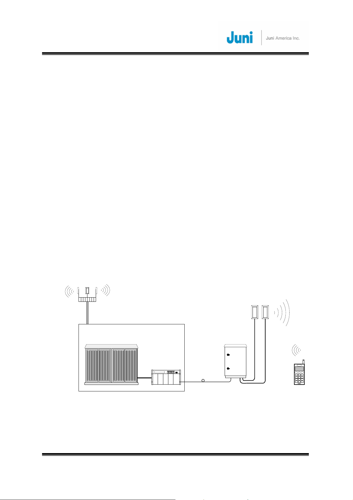
UL_1
Ant.
DL/UL_0
Base Station
BTS
Donor
Optic Link
Ant.
Remote
[FIGURE 1.1.1] SYSTEM CONFIGURATION
Revision 0.01 J
9
uni America Inc.

JUNI JF-46-E1900/CFN03
CDMA FIBER FED REPEATER OPERATIONS MANUAL
JUNI AMERICA PROPRIETARY & CONFIDENTIAL
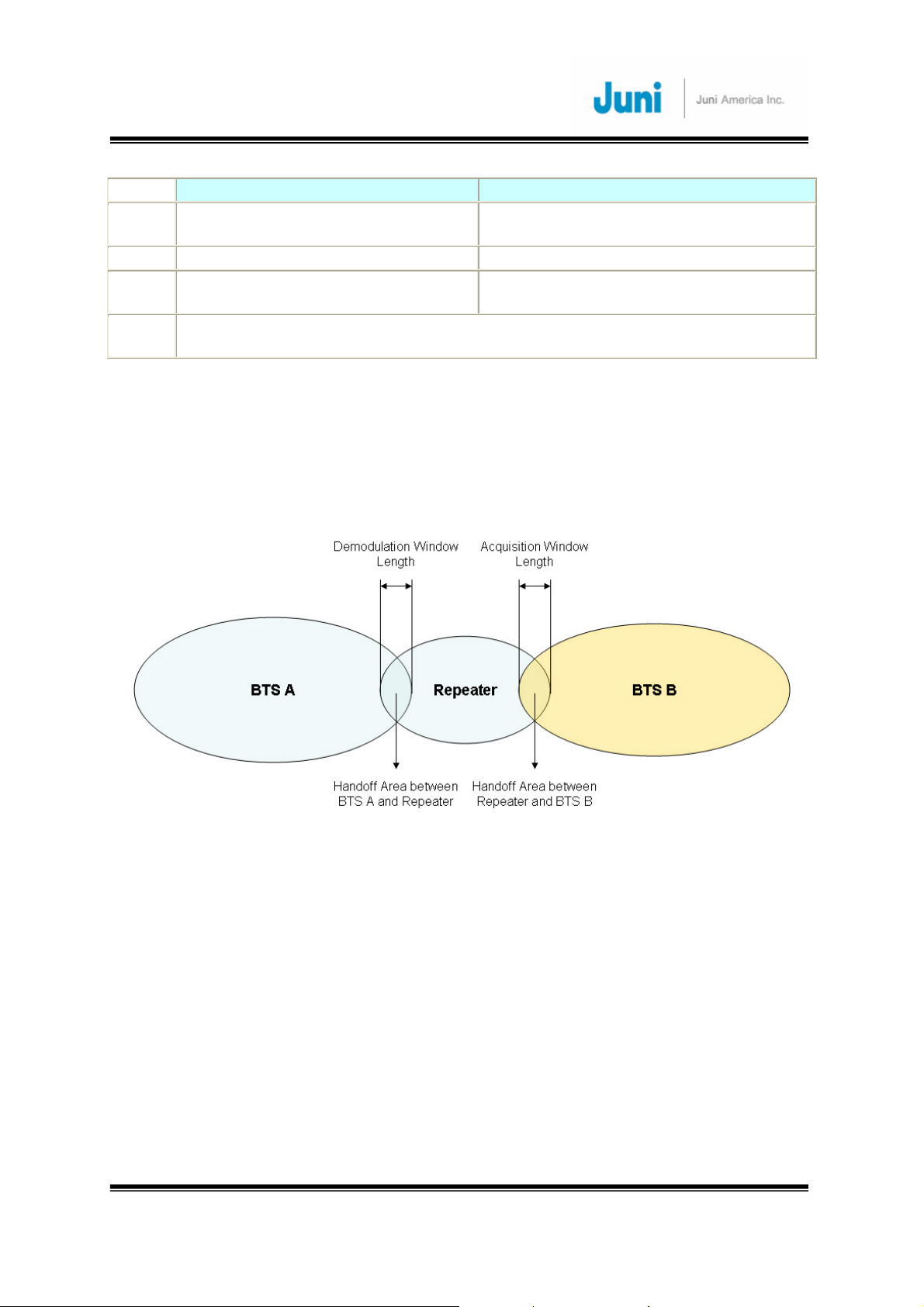
1.2 Search Window
The purpose of using a repeater is to extend the coverage of the BTS by re-
transmitting the BTS signals to mobile stations in a non BTS coverage area. This
means that the BTS handles all kinds of call processing including calls being received
via the repeater. There may be a negative impact of service on the BTS if the
interface between BTS and repeater does not operate properly.
There would be an increase in time delay with calls received from the repeater,
compared to a call from its BTS coverage. Thus the additional delay introduced from
calls via the repeater must be considered while setting BTS parameters.
Window-size is the time range of the BTS traffic channel to search for the signal
originating from the MS. If the delayed signal is out of window-size, the BTS cannot
acquire the signal, which will result in dropped calls due to chip-delay.
Table 1.2.1 describes the two parameters used for controlling the window length, to
prevent the deterioration of call quality caused by chip delay. It is required to search
the signal properly by adjusting the two parameters.
Acquisitioin_Window_Length is adjusted to change the window size used to
search/monitor the neighboring PN and allow soft handoff while traveling to the
neighboring BTS where new traffic channels will be allocated to the MS.
Demodulation_Window_Length is adjusted to change the window size which searches
for the Rx signals. This parameter should be adjusted when the delay (with no change
of traffic channel) between transmission and reception is increased i.e. MS in repeater
service area.
Revision 0.01 J
10
uni America Inc.
JUNI JF-46-E1900/CFN03
CDMA FIBER FED REPEATER OPERATIONS MANUAL
JUNI AMERICA PROPRIETARY & CONFIDENTIAL
Purpose
Unit 1/8 chip/unit 1/8 chip/unit
Remark
Notice
Acquisition_Window_Length Demodulation_Window_Length
Window Range of BTS traffic channel
to search for time sync of other BTS
Use this parameter when traffic
channel is changed (Soft hand off)
Window Range of BTS traffic channel to
search multi path referring to the time-offset
Use this parameter when traffic channel is
not changed. (Tracking multi path signal)
Too big a Window_size causes increase of time for the mobiles to search for BTS
signal. It should be set up with proper values considering time delay.
[Table1.2.1] Two Parameters for Search Window Setup
Therefore, the two parameters stated can be used to adjust the interface between
the BTS and the repeater considering the movement of the MS. Picture 1 shows an
example of two window size parameters for the JF-46 repeater application.
[FIGURE 1.2.1] HANDOFF BETWEEN BTS AND REPEATER
The Demodulation_Window_Length is used to adjust the time sync to compensate
the chip delay introduced by the optic core when the MS moves into the repeater
coverage area.
When the MS travels from the repeater coverage to the BTS B area,
Acquisition_Window_Length is used to adjust this time offset differences. With this
adjustment, the MS will be able to perform soft handoff from BTS A traffic channel
(while in repeater coverage) to the BTS B traffic channel.
Without these adjustments, there may have been two call drops while the MS traveled
from BTS A to BTS B.
Revision 0.01 J
11
uni America Inc.

JUNI JF-46-E1900/CFN03
CDMA FIBER FED REPEATER OPERATIONS MANUAL
JUNI AMERICA PROPRIETARY & CONFIDENTIAL
1.3 Total Optical Delay (Window Size)
With the adjustments described above, good call quality should be maintained without
call drops. This section will show how to calculate the total delay and how the
parameters should be set up in the BTS. The equation below is an example of total
delay for an optic repeater.
SD(μsec) + OD(km) + RD(μsec) + RR(km)
SD : BTS System Delay (Time delay between antenna input port and demodulator in BTS)
OD : Optic Distance between BTS and repeater.
RD : Repeater System Delay
RR : Repeater Coverage Radius
* 1 chip = around 244 m
The total chip delay of 2km of RR and 5km of OD is as below.
36chip + 5000m(20.63chip) + 5 μ sec(6.6chip) + 2000m(8.25chip) = 71.45 chips (Approx.
72chips)
Based on the calculation of total chip delay, the two parameters should be adjusted for
good call quality when installing a new repeater. 71.45 chip delay corresponds to 12
(set value) Search window size (Size = 160 chips). Therefore, the
demodulation_window_length of BTS A should be set up as 12 in this configuration
and acquisition_window_length of BTS A and BTS B should also be set up as 12.
The table below shows the Search window size values for different optic distances
and repeater coverage.
OD + RR Search Window Size
km chip
1 4.13 42.6 46.73 93.45
SD + RD
(Chips)
Sum
(Chips)
2 x Sum
(Chips)
Set Value Size (Chips)
11
114
2 8.25 42.6 50.85 101.70
3 12.38 42.6 54.98 109.95
4 16.50 42.6 59.10 118.20
5 20.63 42.6 63.23 126.45
6 24.75 42.6 67.35 134.70
7 28.88 42.6 71.48 142.95
8 33.00 42.6 75.60 151.20
Revision 0.01 J
uni America Inc.
12
12
12
12
12
12
13
160
160
160
160
160
160
226
12
JUNI JF-46-E1900/CFN03
CDMA FIBER FED REPEATER OPERATIONS MANUAL
JUNI AMERICA PROPRIETARY & CONFIDENTIAL
9 37.13 42.6 79.73 159.45
10 41.25 42.6 83.85 167.70
11 45.38 42.6 87.98 175.95
12 49.50 42.6 92.10 184.20
13 53.63 42.6 96.23 192.45
14 57.75 42.6 100.35 200.70
15 61.88 42.6 104.48 208.95
16 66.00 42.6 108.60 217.20
17 70.13 42.6 112.73 225.45
18 74.25 42.6 116.85 233.70
19 78.38 42.6 120.98 241.95
20 82.50 42.6 125.10 250.20
21 86.63 42.6 129.23 258.45
22 90.75 42.6 133.35 266.70
23 94.88 42.6 137.48 274.95
24 99.00 42.6 141.60 283.20
25 103.13 42.6 145.73 291.45
26 107.25 42.6 149.85 299.70
27 111.38 42.6 153.98 307.95
28 115.50 42.6 158.10 316.20
29 119.63 42.6 162.23 324.45
30 123.75 42.6 166.35 332.70
[Table1.3.1] Example Table for Search Window Size
1.4 FFR Components
The JF-46 FFR system comprises of two main elements, a DHU and RU.
13
13
13
13
13
13
13
14
14
14
14
14
14
14
14
14
14
14
14
15
15
15
226
226
226
226
226
226
226
320
320
320
320
320
320
320
320
320
320
320
320
452
452
452
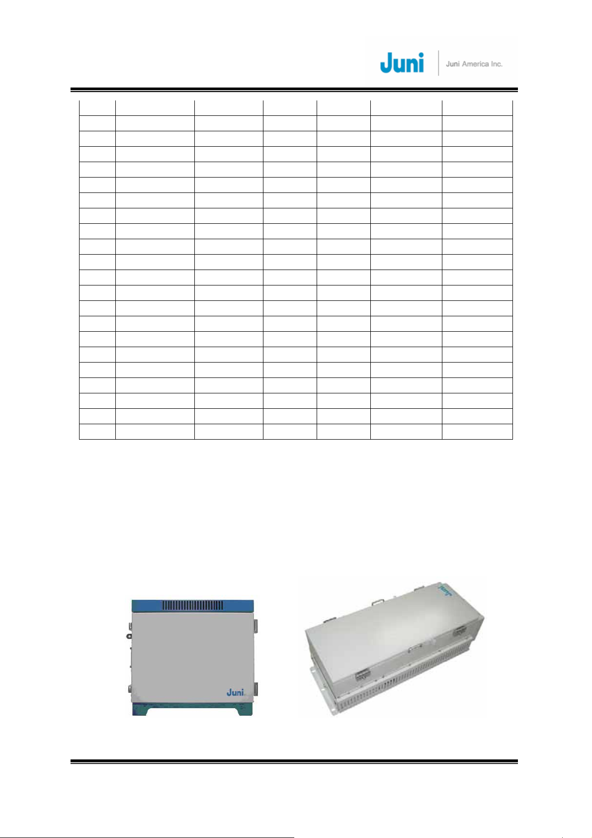
[FIGURE 1.4.1] DONOR HUB UNIT ENCLOSURE [FIGURE 1.4.2] REMOTE UNIT
Revision 0.01 J
13
uni America Inc.

JUNI JF-46-E1900/CFN03
CDMA FIBER FED REPEATER OPERATIONS MANUAL
JUNI AMERICA PROPRIETARY & CONFIDENTIAL
The DHU Enclosure includes the following:
• Donor Optic Module
• Donor Tx/Rx (FSK Modem included) Module
• Control Module
• Wireless Modem
• Power Supply.
Donor Hub Unit transforms the RF signals from the BTS into optic signals, and then the
optic signals are transmitted to Remote Unit.
Donor Hub Unit also transforms the optic signals from Remote Unit into RF signals, and
then the RF signals are transmitted to the BTS.
The RU includes the following:
• Remote Optic Module
• Control Module
• LPA
• LNA
• Cavity BPF
• Power Supply
Remote Unit transforms the optic signals from the Donor Hub Unit into RF signals, and
then the RF signals are transmitted to Antenna.
Remote Unit also transforms the RF signals from Antenna into optic signals, and then the
optic signals are transmitted to the Donor Hub Unit.
1.5 Advantages
There are many advantages to deploying a FFR.
• Supports adjacent block interference protection which allows just one model of the
FFR to cover the entire PCS frequency range.(Changing the Cavity BPF) The FFR
is settable to allow a combination of 94 different frequencies to be serviced. This
advanced filtering personality prevents interference from adjacent frequency
blocks.
• Allows for versatile deployment architectures. Extra optical transceiver modules
Revision 0.01 J
14
uni America Inc.

JUNI JF-46-E1900/CFN03
CDMA FIBER FED REPEATER OPERATIONS MANUAL
JUNI AMERICA PROPRIETARY & CONFIDENTIAL
can be added to the DHU to increase service coverage. A flexible RF splitter unit
can also be implemented to combine multiple RF ports supported by newer BTS.
• The slim and sleek appearance of the RU allows it to be installed and deployed in
difficult zoning areas.
• The water and moisture resistant IP55-rated design make it reliable and durable.
• The FFR system is monitored and controlled from a central remote location by
making use of a CDMA wireless modem via the SNMP protocol.
• Operation, maintenance and repairs are simple. The system provides alarms and
information on the repeater gain settings, output level control, LPA on/off, internal
temperature monitoring and problems concerning the optic module. The system is
designed to operate with a comprehensive network management system.
• The system uses only one optical fiber core for transmission and reception of
signals. To achieve this, WDM is implemented which enables multiple wave-
lengths (DL: 1510nm, UL0: 1530nm, UL1: 1570nm) to be simultaneously
transmitted and received through the one optical fiber core.
1.6 Key Features
• Uses only 1 optical fiber core for DL, UL0 and UL1
• 1xEV-DO and 1xEV-DO Rev. A are supported
• 40 watts composite RF output
• Rx diversity is standard and provides up to 2~8dBo reverse link benefit
• Provides lower life cycle costs by:
9 Reducing fiber lease costs per core
9 Reducing the number of optic cables required for new installations
Revision 0.01 J
15
uni America Inc.

JUNI JF-46-E1900/CFN03
CDMA FIBER FED REPEATER OPERATIONS MANUAL
JUNI AMERICA PROPRIETARY & CONFIDENTIAL
• Most responsive and highly innovative product features
9 Remote unit’s standard powering is 115-230 VAC(Free voltage)
9 Multiple mounting options including; wall, pole and floor/pedestal.
• Supports simulcasting of up to 4 RU per sector with one DHU
9 Reduced pilot pollution, better call quality, reduced soft handoff
9 Better network efficiency and equipment utilization
9 Existing base station equipment could be deployed elsewhere
9 Donor RF Combiner is compatible with newer base station having multiple DL
output RF ports and provides Future-Proof BTS interface
SECTION SPEC OTHERS
Donor shelf size 482.6*266*400mm3(W*H*D) Donor self
Enclosure size 538*545*615.5mm3(W*H*D) Enclosure
Remote Weight <= 180 lbs Remote Weight
Remote Size 396*875*418mm3(W*H*D) Remote Size
Arrester Lightning Protection on all RF
Interface connectors
Remote RF Connector 7/16 DIN Female connectors Remote RF Connector
Donor RF Connector Donor shelf: SMA Female
Enclosure: N Female
Power
MS3102A18-21P (3pin male) Remote AC
Connector
MS3102A18-21P (3pin male) Donor AC
MS3102E20-23P (2pin male) Battery
Arrester
Donor RF Connector
115-230 VAC(Free voltage)
115-230 VAC(Free voltage)
(Charging Current : 2A_max)
Revision 0.01 J
16
uni America Inc.
JUNI JF-46-E1900/CFN03
CDMA FIBER FED REPEATER OPERATIONS MANUAL
JUNI AMERICA PROPRIETARY & CONFIDENTIAL
1.7 General Safety Precautions
This equipment contains components that emit laser radiation which can
seriously damage the retina of the eye. Do not look into the ends of any
optical fiber. Do not look directly into the optical transceiver of any digital unit
or exposure to laser radiation may result. An optical power meter or
reflectometer should be used to verify active fibers. Place a protective cap or
lid immediately over any radiating transceiver or optical fiber connector to
avoid potential damage caused by radiation exposure. This practice also
prevents dirt particles entering the openings.
The optical fiber emits radiation. Do not look directly into the ends of an
optical fiber. This may result in exposure to radiation. Do not assume laser
power is turned off or the fiber is disconnected at the other end.
Wet locations and conditions will increase the risk of electrical shock when
installing or using electrical powered equipment. To prevent electrical shock,
never install or use electrical equipment in wet locations or during lightning
storms.
The DHU is powered by 115-230 VAC. To prevent electrical shock when
installing or maintaining the DHU, disconnect the wiring at the power source
before working with un-insulated wires or terminals.
The RU is typically powered by 115-230 VAC. To prevent electrical shock
when installing or maintaining the RU, disconnect the wiring at the power
source before working with un-insulated wires or terminals.
Always consider and allow sufficient fiber length to permit routing or patch
cords and pigtails without severe bends. Fiber optic patch cords or pigtails
may be permanently damaged if bent or curved to a radius of less than 2
inches (50mm).
Revision 0.01 J
17
uni America Inc.
JUNI JF-46-E1900/CFN03
CDMA FIBER FED REPEATER OPERATIONS MANUAL
JUNI AMERICA PROPRIETARY & CONFIDENTIAL
Static electricity means no risk of personal injury but it can severly damage
and corrupt essential circuitry within the equipment, if not handled carefully.
Parts on the printed circuit boards as well as other parts in the equipment are
sensitive to electrostatic discharge.
Never touch the printed circuit boards or uninsulated conductor surfaces
unless absolutely necessary.
If the printed circuit boards must be handled, always use ESD protective
devices or first touch the enclosure with your hand and then do not move
your feet.
This equipment is only intended to be installed by professionally qualified
and trained personnel.
Risk of explosion if battery is replaced by an incorrect type. Dispose of used
batteries according to the instructions.
Revision 0.01 J
18
uni America Inc.
JUNI JF-46-E1900/CFN03
CDMA FIBER FED REPEATER OPERATIONS MANUAL
JUNI AMERICA PROPRIETARY & CONFIDENTIAL
2. System Description
2.1 FFR System
The JF-46 FFR is made up of a main Donor Hub Unit (DHU) and a RU. The DHU and
RU are divided into modules to allow easy operation and maintenance. It can operate
even in the harshest environmental conditions due to its durable IP55-rated
weatherproof enclosure.
[FIGURE 2.1.1] SYSTEM BLOCK DIAGRAM
2.2 Simulcast Operation
Please refer to Figure 2.2.1 for a system block diagram of a Simulcast FFR
configuration, where a single BTS sector provides coverage to two Remote Units. This
configuration employs two RF Splitter/Combiner units at the RF ports of the Donor
Hub Unit which relate to the two Remote Units.
On the DL path, the BTS signal is split two ways and feeds two DHU input ports.
Similarly, on the UL path, the signals from two DHU RF ports are summed and fed to
one port of the BTS.
Revision 0.01 J
19
uni America Inc.
JUNI JF-46-E1900/CFN03
CDMA FIBER FED REPEATER OPERATIONS MANUAL
JUNI AMERICA PROPRIETARY & CONFIDENTIAL
The JF-46 FFR has adequate RF gain margin to support a Splitter/Combiner as
shown with loss of up to 10 dB. As a result, a single BTS sector can easily feed 4 or
even 8 Remote Units. If more than 4 Remote Units are to be supported, more than
one DHU is required since a DHU can support only a maximum of 4 Optic Modules,
which drive 4 Remote Units.
[FIGURE 2.2.1] SIMULCAST BLOCK DIAGRAM
Revision 0.01 J
20
uni America Inc.
JUNI JF-46-E1900/CFN03
CDMA FIBER FED REPEATER OPERATIONS MANUAL
JUNI AMERICA PROPRIETARY & CONFIDENTIAL
2.3 Donor Hub Unit
This section describes the main components of the DHU, the functions performed by
the components and the user interface.
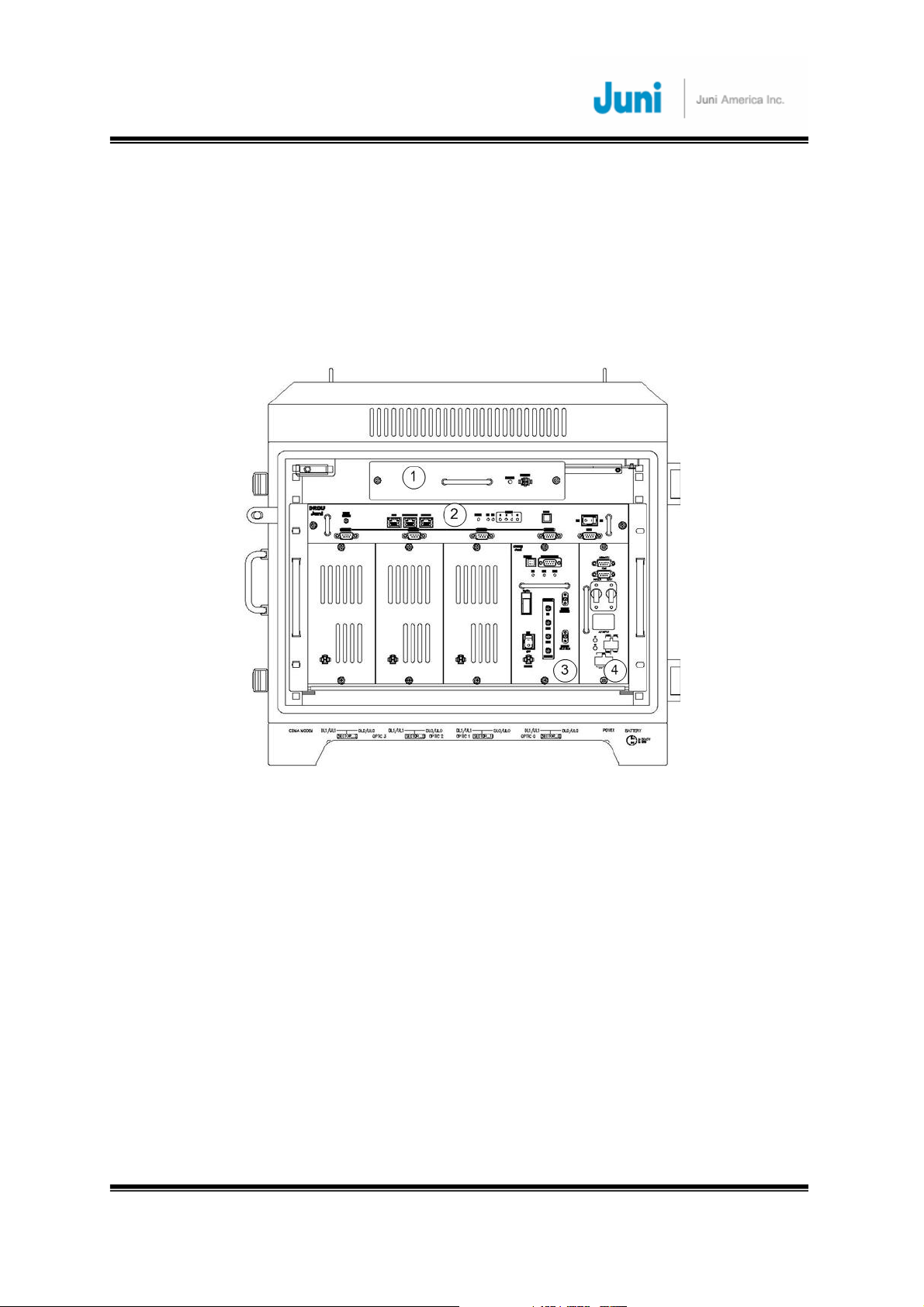
2.3.1 Donor Hub Unit Enclosure and Shelf
[FIGURE 2.3.1] MAIN COMPONENTS OF THE DONOR HUB UNIT
① FAN: Provides ventilation and disperses heat evenly.
② DRCU (Donor Repeater Control Unit): Monitors and controls each internal
module. Also monitors and controls the RU by data communication. Monitoring
the control and status of all repeaters can only be managed at an
administrative level via the internal SNMP agent.
③ OTRU(Optic Transceiver Unit): Converts the RF signal (from the BTS) into an
optical signal and transmits the signal to the RU. Conversely, the RU converts
the optic signal and transmits it to the BTS.
④ PSU (Power Supply Unit): Converts the input power AC power (115-230VAC, free
voltage) into DC+27V, DC+15V, DC +7V and supplies the power to the modules.
Revision 0.01 J
uni America Inc.
21
JUNI JF-46-E1900/CFN03
CDMA FIBER FED REPEATER OPERATIONS MANUAL
JUNI AMERICA PROPRIETARY & CONFIDENTIAL
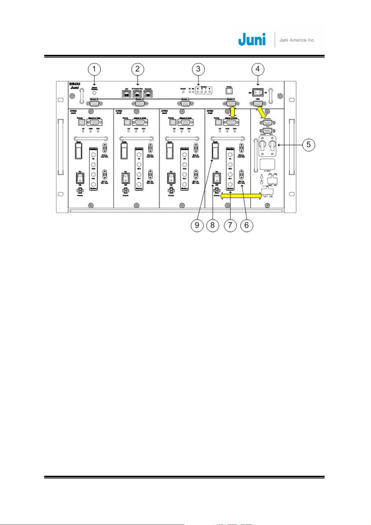
[FIGURE 2.3.2] DONOR HUB UNIT SHELF INTERFACE
① CDMA Modem RF Port (Female SMA-Type): An RF cable connects the CDMA
wireless modem port on the DRCU to the modem RF port situated on the
outside of the enclosure in case of outdoor type.
② Debug and Ethernet port: Ethernet port to allow connection to any PC for
debugging via the GUI, allow connection to IP Control Box for SNMP
③ DRCU and SNMP reset Key and LEDs: Hard reset button to restart the DRCU and
SNMP agent. LEDs to display the status of the System.
④ DRCU Power switch: Turns the power on/off for the DRCU only.
⑤ Main and battery power switch: Main power switch located on the power supply
which provides power to the entire DHU.
⑥ RF in/out port (Female SMA): RF ports on a single optic transceiver supports
only one sector. This port is connected to the enclosure with RF cables.
⑦ Monitoring port (Female SMA): Ports used to monitor signals existing within the
DHU with a spectrum analyzer or test equipment.
⑧ OTRU Power switch: Turns the power on/off for the OTRU only.
⑨ Optic connector : Connector to where the fiber is connected to.
Revision 0.01 J
uni America Inc.
22
JUNI JF-46-E1900/CFN03
CDMA FIBER FED REPEATER OPERATIONS MANUAL
JUNI AMERICA PROPRIETARY & CONFIDENTIAL
⑩
: Data and power cable
1 2 3
4 4
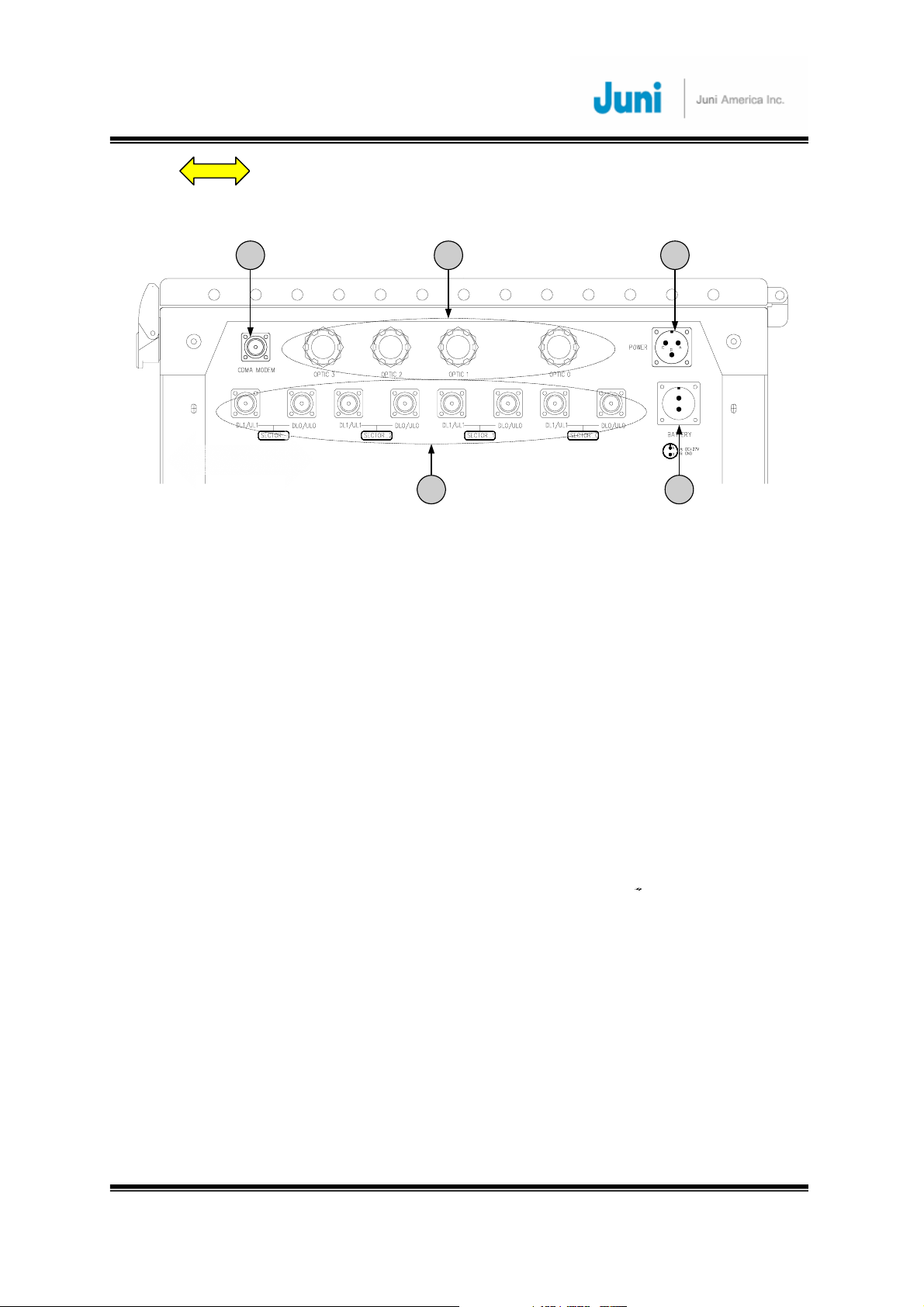
[FIGURE 2.3.3] DONOR HUB UNIT EXTERNAL CONNECTORS (BOTTOM VIEW)
① CDMA modem RF port (Female N-Type): External Antenna for modem connected
to this port.
② Fiber Entrance: The fiber is passed through to connect to the optic transceiver.
③ AC power connector (Female weatherproof MS type): Connectors used for AC
powering. The AC power cable is supplied by the manufacturer.
④ RF in/out port (Female N type): Provides connection to the BTS.
⑤ Battery connector (Female weatherproof MS type): Connector for backup battery
unit.
2.3.2 Wireless Modem Antenna
The technical requirements for the Wireless Modem Antenna are dependent on the
specific DHU location and network coverage. If the nearest BTS with a local antenna
is nearby the DHU, a 3 dBi Gain Omni antenna should be quite adequate. The
Modem Antenna is to be connected to the modem antenna connector on the DHU.
In the event the nearest BTS with a local antenna is quite some distance from the
DHU, a directional antenna with 10 dBi Gain, aimed at the nearest BTS with the local
antenna, is the appropriate modem antenna solution.
Revision 0.01 J
23
uni America Inc.
JUNI JF-46-E1900/CFN03
CDMA FIBER FED REPEATER OPERATIONS MANUAL
JUNI AMERICA PROPRIETARY & CONFIDENTIAL
2.4 Remote Unit
This section describes the main components of the RU, the functions performed by
the components and the user interface.
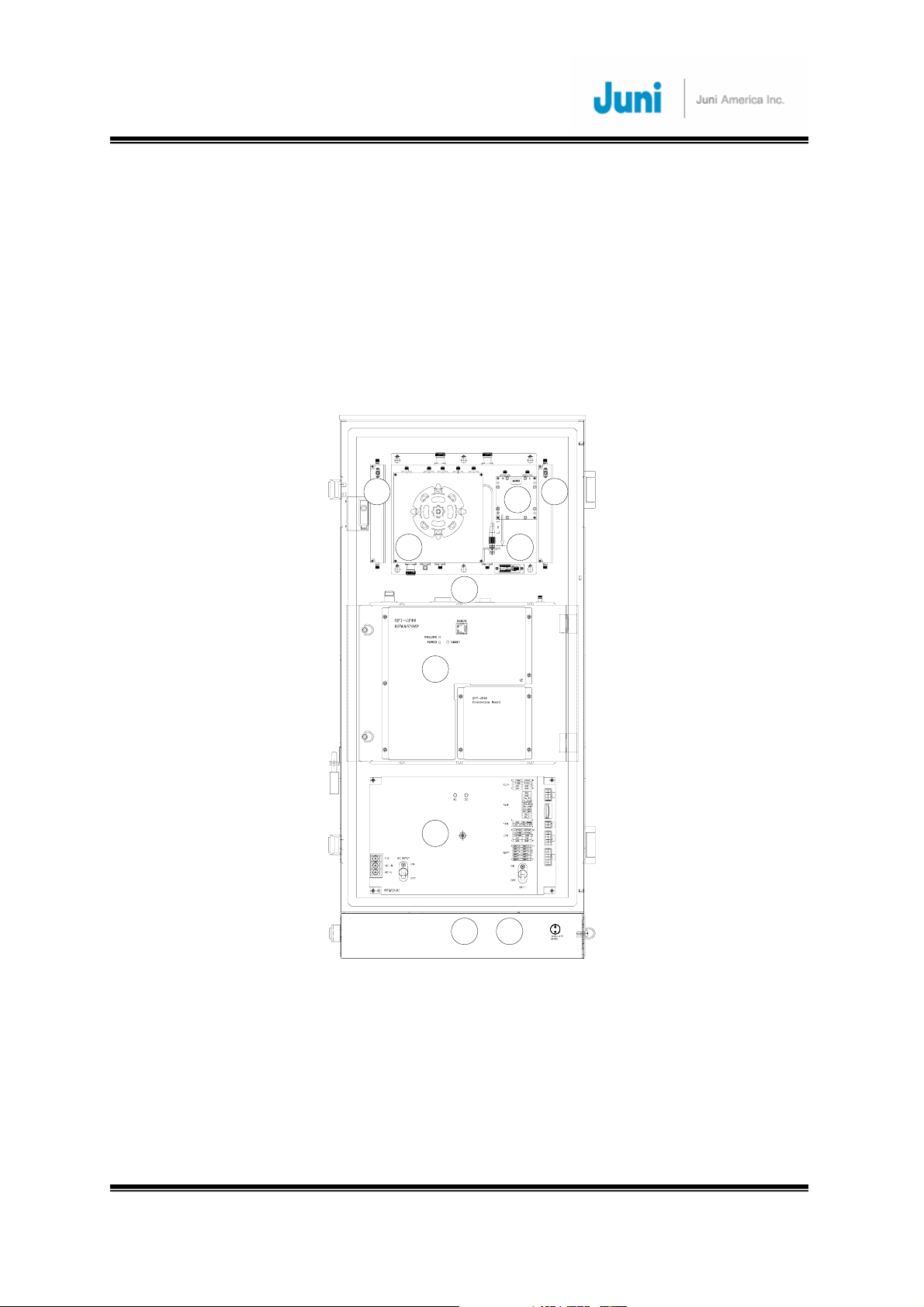
2.4.1 Remote Unit
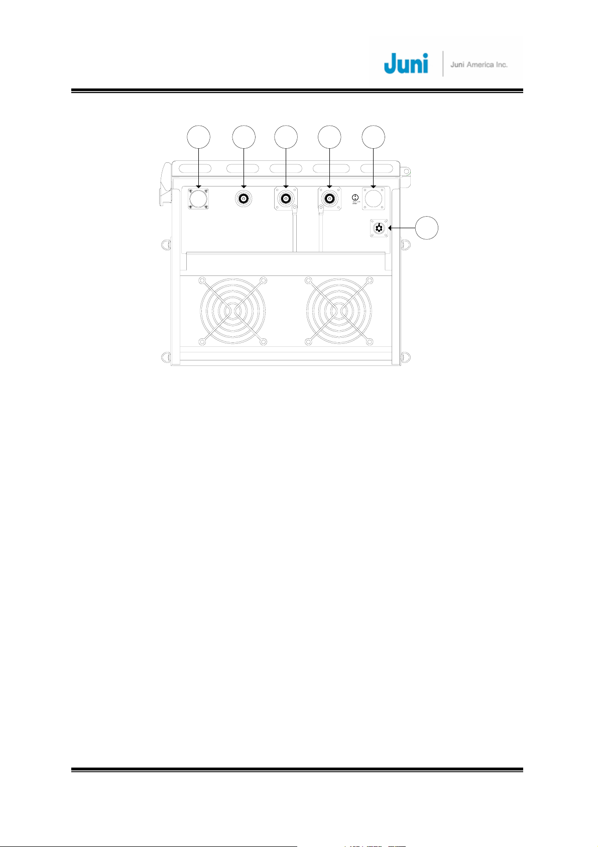
350_IN
320_OUT
UL0_IN
DL_OUTUL1_IN
NMS
NMS
44
3
3
SPT-JF46
1 2
Remote_Optic Module
5
6
7
8 8
UL_1
AC_IN
[F
IGURE 2.4.1] MAIN COMPONENTS OF THE REMOTE UNIT
OPTIC
DL/UL_0
BATTERY(Max 0.7A)
① Remote Optic Module: Converts the optic signal (from DHU) into RF signal.
Conversely, it converts the RF signal (from the RU) into an optic signal.
② Duplexer & BPF: Filters out the unwanted signals on the FWD and REV path.
③ FSK Modem: Modem for communications between the DHU and the RU.
④ Low Noise Amplifier (LNA): Performs low noise amplification on received signals.
Revision 0.01 J
uni America Inc.
24

JUNI JF-46-E1900/CFN03
CDMA FIBER FED REPEATER OPERATIONS MANUAL
JUNI AMERICA PROPRIETARY & CONFIDENTIAL
⑤ LPA (Linear Power Amplifier): A 60 Watt 6 carrier amplifier which amplifies the
signal into high output power for transmitting to the DL antenna. The amplifier is
operated by +30VDC and has a 43dB Gain.
⑥ Control Module: Used to monitor and control the RU. Also manages the
communication with the DHU.
⑦ Power Supply: Converts the input power (115-230VAC, free voltage) into DC+30V,
DC +7V and supplies this power to the modules. Also, turns the FAN On/Off by
detecting the internal temperature of the unit and alerting the Control module (⑥)
the current status of the FAN .
⑧ Arrestor: Protects the system against lightning surges. No external lightning
arrestors are required.
Revision 0.01 J
25
uni America Inc.
JUNI JF-46-E1900/CFN03
CDMA FIBER FED REPEATER OPERATIONS MANUAL
JUNI AMERICA PROPRIETARY & CONFIDENTIAL
2.4.2 Remote Unit Connectors
1
AC_IN
2 3 4 5
OPTIC
DL/UL_0
UL_1
BATTERY(Max 0.7A)
A
F
B
E
C
D
FAN
6
[FIGURE 2.4.2] REMOTE UNIT EXTERNAL CONNECTORS (BOTTOM VIEW)
① AC power connector: Male AC power connector to allow connection for a female
MS3102 Type AC power connector and AC power feeder cable.
② Fiber entrance port: A non metallic liquid tight strain relief is connected to the port
with a fiber core fed through the center into the RU.
DL/UL0 path in/out port: Female DIN type DL/UL path port making use of a single
③
fiber core for full duplex operation. An antenna is connected to this port to transmit
and receive signals.
④
UL1 path input port: Female DIN type Diversity uplink/receive path port to connect
a second antenna
⑤ Battery connector: A weatherproof two pin MS connector used to connect an
external battery backup unit.
⑥
FAN connector: A weatherproof six pin MS connector used to connect the fan unit.
Revision 0.01 J
26
uni America Inc.

JUNI JF-46-E1900/CFN03
CDMA FIBER FED REPEATER OPERATIONS MANUAL
JUNI AMERICA PROPRIETARY & CONFIDENTIAL
3. Installation
3.1 Transportation to the Site
During transportation of the repeater to the site, the following points need to be
considered.
• While transporting the repeater unit, it is advised to pack the repeater in its
original packaging supplied by Juni America.
• It is important to prevent any shock applied to the repeater units while
loading/unloading to/from the vehicle.
• During transportation, it is advised to prevent or minimize any movement of the
packed repeater units.
3.2 Handling of the Repeater
The user should prevent any defect caused by an accident, misuse, abuse, insect
infestations, “Acts of God”, improper installation or operation, lack of reasonable care,
unauthorized modification, and loss of parts, tampering or any repair by a person not
authorized by Juni America. As the JF-46 repeater is heavy equipment, the installer
should be careful and seek assistance while attempting to lift/carry/move the units.
3.3 Installation Conditions
• Avoid direct sunlight and place the repeater in a well ventilated location.
• The environment temperature should be in a range of –20°C to +55°C.
• Ground connections should be made to all metal cabinets for safety.
• Avoid any vibration.
• The VSWR of the cable which connects the repeater to the antenna should be less
than 1:1.5
Revision 0.01 J
uni America Inc.
27

JUNI JF-46-E1900/CFN03
CDMA FIBER FED REPEATER OPERATIONS MANUAL
JUNI AMERICA PROPRIETARY & CONFIDENTIAL
3.4 Inspection before Installing the Repeater
• Check for any physical damage on the repeater cabinet. If any damage is found, it is
advised to perform close inspection on the operating features and RF signal test to
verify repeater performance.
• Check for loose RF cables inside the repeater.
• Check whether any part of the cabinet is exposed to water or other liquid substances.
• Before installing the repeater, check the serial number of the units to be installed.
• Check all required accessories are available.
3.5 JF-46 FFR Installation Procedure
3.5.1 Tools and Materials
The following tools and materials are required in order to complete the procedures in
the installation process. The installation processes include RF testing and mechanical
installation.
Test equipment required for commissioning by the customer
• RF signal generator
• Portable RF Spectrum analyzer or RF power meter
• RF adaptors
• AC/DC voltmeter
• External attenuators (high power and low power)
• MS3102A18-21S Female power feeder connector
• RF test cables
• 99% pure alcohol wipes
• PC with Internet Explorer software installed
• Optical TDR (Time Domain Reflectometer)
• Butyl tape (rubber tape)
• Electric tape
• RJ-45 Ethernet interface cable
• Various tools such as screwdrivers, spanners etc
• Wireless terminal
• Pencil or pen
• Writing pad
Revision 0.01 J
28
uni America Inc.
 Loading...