

Inkel JF43E1900CFN03 Users Manual
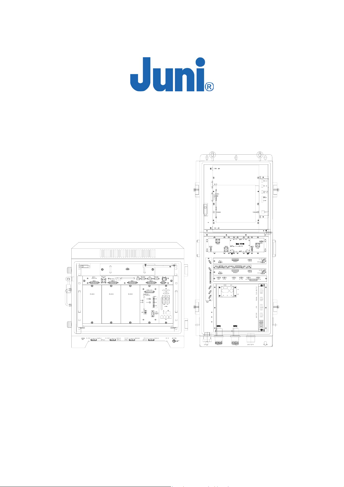
JF43
Fiber Fed Repeater
RX IN
26 0 IN
NMS
520 OUT
22 0 OUT
NMS
TX OUT
O
PERATIONS MANUAL
Version 1.17
September 2005
© Juni America Inc.

JUNI JF43-E1900/CFN03
CDMA FIBER FED REPEATER OPERATIONS MANUAL
CONTENTS
LIST OF ACRONYMS AND ABBREVIATIONS......................................................... 5
1. INTRODUCTION ................................................................................................. 7
1.1 FIBER FED REPEATER............................................................................................7
1.2 FFR COMPONENTS................................................................................................8
1.3 ADVANTAGES .........................................................................................................9
1.4 KEY FEATURES ....................................................................................................10
1.5 GENERAL SAFETY PRECAUTIONS .........................................................................11
2. SYSTEM DESCRIPTION................................................................................... 13
2.1 FFR SYSTEM .......................................................................................................13
2.2 DONOR UNIT........................................................................................................13
2.2.1 Donor Hub Unit Enclosure and Shelf.......................................................14
2.3 REMOTE UNIT ......................................................................................................17
2.3.1 Remote Unit.............................................................................................17
2.3.2 Remote Unit Connectors .........................................................................19
2.3.3 Remote Dip Switch Settings....................................................................20
3. INSTALLATION................................................................................................. 21
3.1 TRANSPORTATION TO THE SITE.............................................................................21
3.2 HANDLING OF THE REPEATER...............................................................................21
3.3 INSTALLATION CONDITIONS ..................................................................................21
3.4 INSPECTION BEFORE INSTALLING THE REPEATER ..................................................22
3.5 JF43 FFR INSTALLATION PROCEDURE .................................................................22
3.5.1 Tools and Materials..................................................................................22
3.5.2 Cautions during Installation .....................................................................23
3.5.3 Optical Fiber Jumper Cable Assembly.....................................................23
3.5.4 Weatherproofing Connectors...................................................................24
3.5.5 Donor Unit Eye Bolts ...............................................................................25
3.5.6 Donor Unit Standard Wall Mount Guide...................................................26
Version 1.17 ⓒ J
uni America Inc. Page 2 of 88

JUNI JF43-E1900/CFN03
CDMA FIBER FED REPEATER OPERATIONS MANUAL
3.5.7 Donor Hub Unit Commissioning and Provisioning...................................27
3.5.8 Remote Unit Eye Bolts.............................................................................29
3.5.9 Remote Unit Standard Wall Mount Guide................................................29
3.5.10 LVAC Cables and Connectors Installation Guide ....................................31
3.5.11 Remote Unit External Powering Configuration (Optional) .......................31
3.5.12 Remote Unit Commissioning and Provisioning........................................33
3.5.13 Operations Tests......................................................................................35
3.5.13.1 Optic Cable Loss Test............................................................................................ 35
3.5.14 Setup Procedure for DL/UL Path Gain ....................................................36
3.5.14.1 Setup for UL Gain .................................................................................................. 36
3.5.14.2 Setup for DL Gain .................................................................................................. 37
3.5.14.3 Caution Items......................................................................................................... 38
3.6 REPLACEMENT OF FAULTY UNITS .........................................................................39
3.6.1 Remote/Donor Unit Replacement............................................................39
3.6.2 Optical Module Replacement...................................................................39
3.7 STORAGE OF THE REPEATER................................................................................40
3.8 SAFETY PRECAUTIONS.........................................................................................40
4. OPERATION...................................................................................................... 41
4.1 INTRODUCTION.....................................................................................................41
4.2 LMT OPERATION (LOCAL MAINTENANCE TERMINAL)............................................41
4.2.1 Introduction..............................................................................................41
4.2.2 Screen Description ..................................................................................41
4.2.3 Communication Settings..........................................................................44
4.2.4 Repeater Setup........................................................................................44
4.2.5 Offset Calibration.....................................................................................45
4.2.6 Repeater Status Monitoring and Control..................................................46
4.2.6.1 Donor Unit Window.................................................................................................... 47
4.2.6.2 Remote Window ........................................................................................................ 50
4.2.6.3 Repeater Settings Setup ........................................................................................... 53
Version 1.17 ⓒ J
uni America Inc. Page 3 of 88

JUNI JF43-E1900/CFN03
CDMA FIBER FED REPEATER OPERATIONS MANUAL
4.2.7 Repeater Download.................................................................................54
4.3 SNMP OPERATION ..............................................................................................57
4.3.1 Introduction..............................................................................................57
4.3.2 Connection Setup for PC to Donor Unit MCU (Master Control Unit) .......57
4.3.3 View and Change SNMP Destination IP..................................................62
4.3.4 Downloading SNMP History Log..............................................................64
4.3.5 Reading and Understanding the SNMP History Log................................66
5. SYSTEM MAINTENANCE................................................................................. 68
5.1 PERIODIC MAINTENANCE......................................................................................68
5.1.1 Donor Unit Fan Maintenance...................................................................68
5.1.2 Remote Unit Fan Maintenance................................................................69
5.2 FAULT DETECTION AND ALARM REPORTING..........................................................69
5.3 TROUBLE SHOOTING FOR THE DONOR UNIT..........................................................76
5.4 TROUBLE SHOOTING FOR THE REMOTE UNIT ........................................................77
7. SYSTEM MAINTENANCE................................................................................. 79
APPENDIX A. JF-43 MECHANICS.......................................................................... 80
1. DONOR UNIT........................................................................................................80
2. REMOTE UNIT ......................................................................................................83
APPENDIX B. BLOCK DIAGRAM........................................................................... 85
APPENDIX C. LVAC CABLES AND CONNECTORS INSTALLATION GUIDE
(CORNING GILBERT) ............................................................................................. 88
Version 1.17 ⓒ J
uni America Inc. Page 4 of 88

JUNI JF43-E1900/CFN03
CDMA FIBER FED REPEATER OPERATIONS MANUAL
List of Acronyms and Abbreviations
The acronyms and abbreviations used in this manual are shown in the following list.
AC Alternating Current
AMP Amplifier
ATT Attenuator/Attenuation
BPF Band Pass Filter
BTS Base Transceiver System
C Centigrade
CATV Cable TV
CDMA Code Division Multiple Access
COM Common
Config Configuration
DC Direct Current
DHU Donor Hub Unit
DL Downlink
DOC Donor Optic Cavity
EMS Element Management System
EVDO Evolution Data Only
FFR Fiber Fed Repeater
FRPS Ferro Resonant Power Supply
FSK Frequency Shift Keying
FTP File Transfer Protocol
FWD Forward
HPA High Power Amplifier
IP Internet Protocol
JF43 Juni Fiber Repeater 43dBm
LD Laser Diode
LED Light Emitting Diode
Version 1.17 ⓒ J
uni America Inc. Page 5 of 88

JUNI JF43-E1900/CFN03
CDMA FIBER FED REPEATER OPERATIONS MANUAL
LMT Local Management Terminal
LNA Low Noise Amplifier
LPA Linear Power Amplifier
LVAC Low Voltage Alternating Current
MCU Master Control Unit
MHz Megahertz
PA Power Amplifier
PC Personal Computer
PCS Personal Communications System
PD Photo Diode
PSU Power Supply Unit
REV Reverse
RF Radio Frequency
RSM Remote unit Saw Module
RU Remote Unit
Rx Receive
SAW Surface Acoustic Wave
SNMP Simple Network Management Protocol
TDR Time Domain Reflectometer
Tx Transmit
UL Uplink
USB Universal Serial Bus
VAC Voltage Alternating Current
VDC Voltage Direct Current
VSWR Voltage Standing Wave Ratio
WDM Wavelength Division Multiplexer
Version 1.17 ⓒ J
uni America Inc. Page 6 of 88
JUNI JF43-E1900/CFN03
CDMA FIBER FED REPEATER OPERATIONS MANUAL
1. Introduction
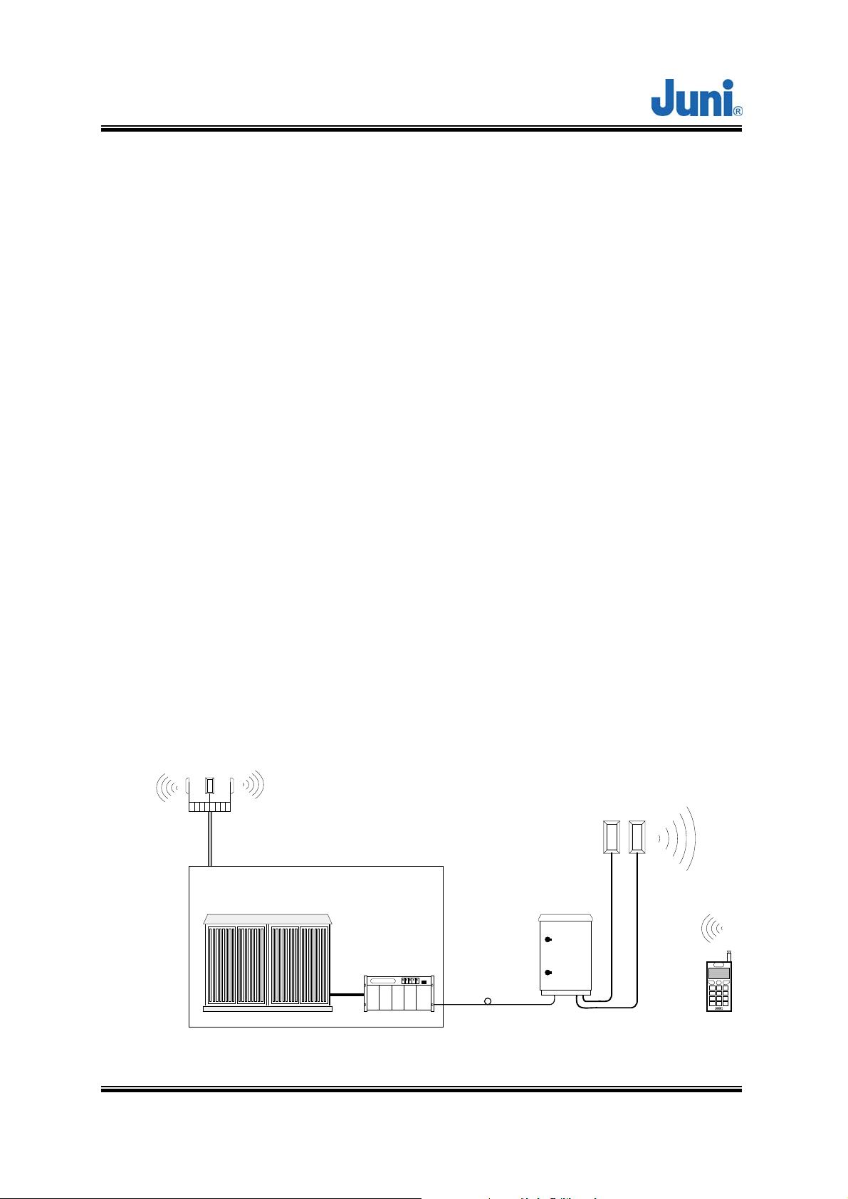
1.1 Fiber Fed Repeater
The JF43 FFR provides a cost effective solution for cell extension coverage and
increased call quality in shadow areas. It is a RF signal transport system that
provides long range RF coverage where it is impractical to install a BTS.
The JF43 FFR is designed to be strategically placed to overcome difficult zoning
issues by allowing the base stations to remain at a central location while placing
antennas at remote locations. RF signals can be transported to remote locations to
expand coverage into areas not receiving service or to extend coverage into difficult
to reach areas such as canyons, tunnels and underground parking lots and roadways.
The JF43 FFR provides a high-tech, highly-efficient service system which enables
high quality communication at low cost, due to the system’s utilization of one optical
fiber core between the DHU and RU supporting full duplex transmission of signals for
both the DL and UL.
UL_1
Ant.
DL/UL_0
Base Station
BTS
Ant.
Remote
Version 1.17 ⓒ J
Donor
Optic Link
[Figure 1.1] System Configuration
uni America Inc. Page 7 of 88
JUNI JF43-E1900/CFN03
CDMA FIBER FED REPEATER OPERATIONS MANUAL
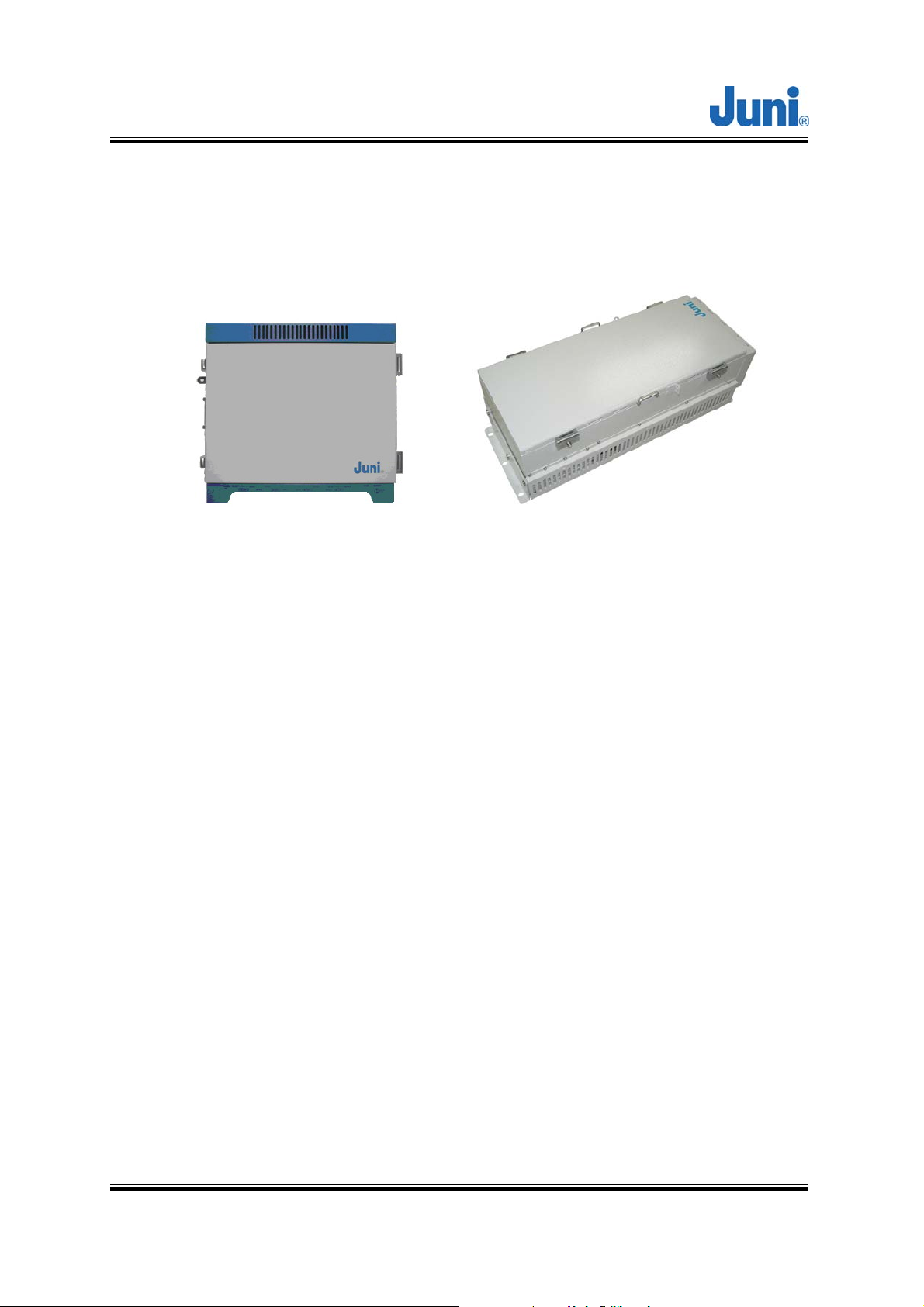
1.2 FFR Components
The JF43 FFR system comprises of two main elements, a DHU and RU.
[Figure 1.2] Donor Hub Unit Enclosure [Figure 1.3] Remote Unit
The DHU Enclosure includes the following:
• Donor Optic Module
• Donor Rx Module
• Donor Tx (SAW, FSK Modem included) Module
• Local Module
• Control Module
• Wireless Modem
• Power Supply.
The RU includes the following:
• Remote Optic Module
• Remote T/Rx Module
• Remote Rx SAW Module
• Control Module
• LPA
• LNA
• Cavity BPF
• Power Supply
Version 1.17 ⓒ J
uni America Inc. Page 8 of 88

JUNI JF43-E1900/CFN03
CDMA FIBER FED REPEATER OPERATIONS MANUAL
1.3 Advantages
There are many advantages to deploying a FFR.
• Supports adjacent block interference protection which allows just one model of the
FFR to cover the entire PCS frequency range. The FFR is settable to allow a
combination of 85 different frequencies to be serviced. This advanced filtering
personality prevents interference from adjacent frequency blocks.
• Allows for versatile deployment architectures. Extra optical transceiver modules
can be added to the DHU to increase service coverage. A flexible RF splitter unit
can also be implemented to combine multiple RF ports supported by newer BTS.
• The slim and sleek appearance of the RU allows it to be installed and deployed in
difficult zoning areas.
• Its water and moisture resistant NEMA 4X structure make it reliable and durable.
• The FFR system is monitored and controlled from a central remote location by
making use of a CDMA wireless modem via the SNMP protocol.
• Operation and maintenance and repair is simple. The system provides alarms and
information on the repeater gain settings, output level control, HPA on/off, internal
temperature monitoring and problems concerning the optic module. The system is
designed to operate with a comprehensive network management system.
• The system uses only one optical fiber core for transmission and reception of
signals. To achieve this, WDM is implemented which enables multiple wave-
lengths (FWD: 1550nm, REV: 1510nm) to be simultaneously transmitted and
received through the one optical fiber core.
Version 1.17 ⓒ J
uni America Inc. Page 9 of 88

JUNI JF43-E1900/CFN03
CDMA FIBER FED REPEATER OPERATIONS MANUAL
1.4 Key Features
• Uses only 1 optical fiber core for Tx, Rx0 and Rx1
• 1xEVDO is supported
• 20 watts composite RF output
• Receive diversity is standard and provides up to 6dB reverse link benefit
• Provides lower life cycle costs by:
Reducing fiber lease costs per core
Reducing the number of optic cables required for new installations
• Most responsive and highly innovative product features
Remote unit’s standard powering is LVAC, 55 to 88 VAC
Low voltage AC powering over coax from DHU to RU
Multiple mounting options including; strand, wall, pole, floor/pedestal and
encapsulated light pole.
• High performance
• Supports simulcasting of up to 4 RU per sector
Reduced pilot pollution, better call quality, reduced soft handoff
Better network efficiency and equipment utilization
Existing base station equipment could be deployed elsewhere.
Donor RF Combiner is compatible with newer base station having multiple Tx
output RF ports. Provides Future-Proof BTS interface
Version 1.17 ⓒ J
uni America Inc. Page 10 of 88

JUNI JF43-E1900/CFN03
CDMA FIBER FED REPEATER OPERATIONS MANUAL
1.5 General Safety Precautions
This equipment contains components that emit laser radiation which can
seriously damage the retina of the eye. Do not look into the ends of any
optical fiber. Do not look directly into the optical transceiver of any digital unit
or exposure to laser radiation may result. An optical power meter or
reflectometer should be used to verify active fibers. Place a protective cap or
lid immediately over any radiating transceiver or optical fiber connector to
avoid potential damage caused by radiation exposure. This practice also
prevents dirt particles entering the openings.
The optical fiber emits radiation. Do not look directly into the ends of an
optical fiber. This may result in exposure to radiation. Do not assume laser
power is turned off or the fiber is disconnected at the other end.
Wet locations and conditions will increase the risk of electrical shock when
installing or using electrical powered equipment. To prevent electrical shock,
never install or use electrical equipment in wet locations or during lightning
storms.
The DHU is powered by 50-88VAC. To prevent electrical shock when
installing or maintaining the DHU, disconnect the wiring at the power source
before working with un-insulated wires or terminals.
The RU is powered by 115VAC. To prevent electrical shock when installing
or maintaining the RU, disconnect the wiring at the power source before
working with un-insulated wires or terminals.
Always consider and allow sufficient fiber length to permit routing or patch
Version 1.17 ⓒ J
uni America Inc. Page 11 of 88

JUNI JF43-E1900/CFN03
CDMA FIBER FED REPEATER OPERATIONS MANUAL
cords and pigtails without severe bends. Fiber optic patch cords or pigtails
may be permanently damaged if bent or curved to a radius of less than 2
inches (50mm).
Version 1.17 ⓒ J
uni America Inc. Page 12 of 88
JUNI JF43-E1900/CFN03
CDMA FIBER FED REPEATER OPERATIONS MANUAL
2. System Description
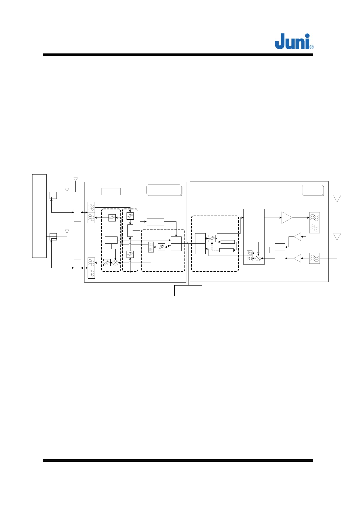
2.1 FFR System
The JF43 FFR is made up of a main unit (DHU) and a RU. The DHU and RU are
divided into modules to allow easy operation and maintenance. It can operate even in
the harshest environmental conditions due to its durable NEMA 4X casing.
Modem Ant.
BTS Ant.
BTS
TX0/RX0
D/C
-30 or -20dB
Cable Loss
-2~-5dB
TX1/RX1
D/C
-30 or -20dB
BTS Ant.
Modem
Combiner
Combiner
Duplexer
Duplexer
TX1
RX1
RX1
TX1
Att.
RX
Local
Att.
Com.
TX
(-10dB)
(-10dB)
Donor Optic Cavity
SAW
AGC(LD,PD)
Optic
O/E
(LD)
E/O
(PD)
Optic AGC
E/O
(PD)
O/E
(LD)
Local
p-Det
Optic
Remote
PA
T/RX Dri ve
BPF
SAW
SAW
LNA
LNA
BPF
2.2 Donor Unit
This section describes the main components of the DHU, the functions performed by
the components and the user interface.
Optic cab le
15 miles_max
[Figure 2.1] System Block diagram
Version 1.17 ⓒ J
uni America Inc. Page 13 of 88
JUNI JF43-E1900/CFN03
CDMA FIBER FED REPEATER OPERATIONS MANUAL
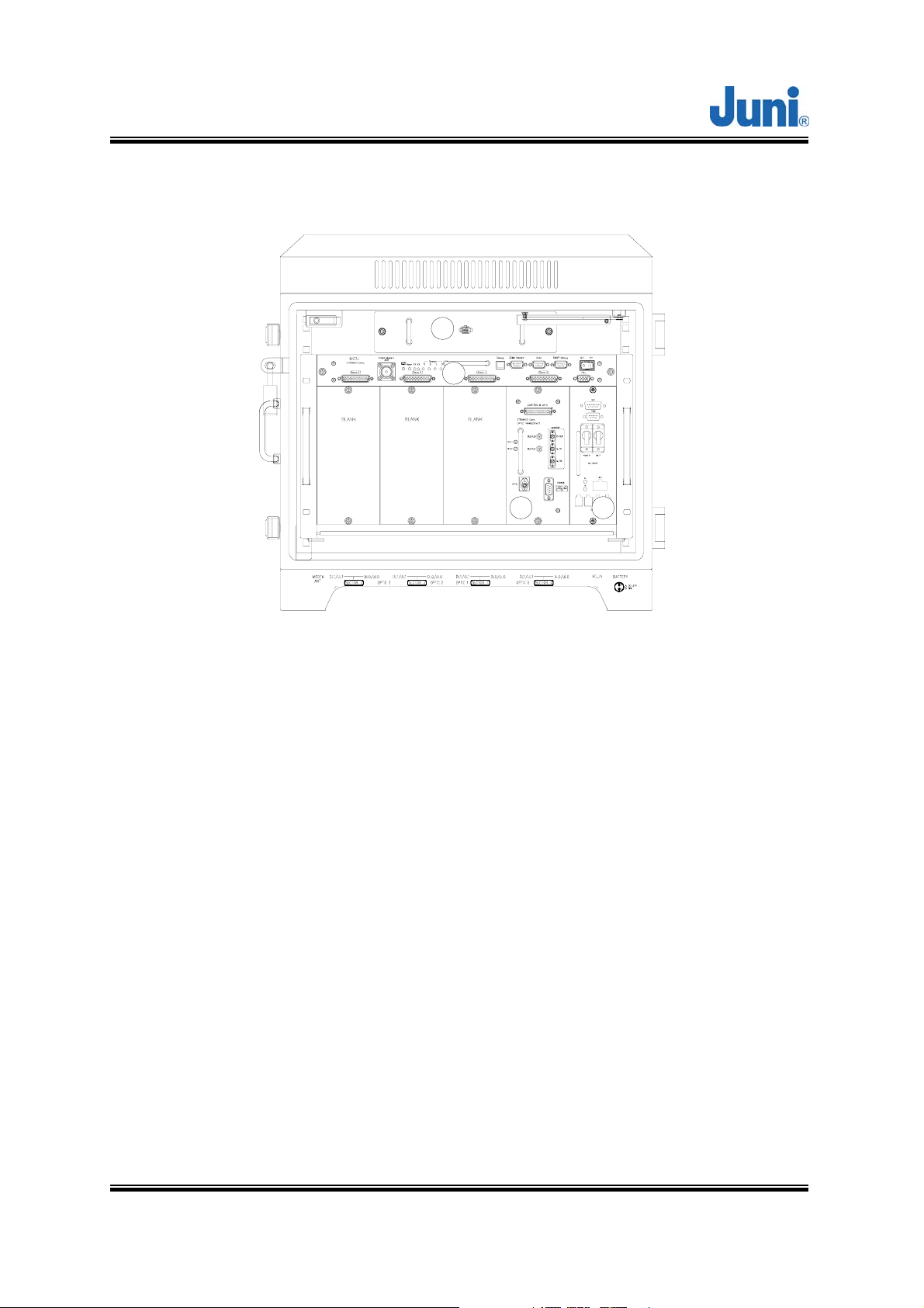
2.2.1 Donor Hub Unit Enclosure and Shelf
1
2
3 4
[Figure 2.2] Main Components of the Donor Hub Unit
① FAN: Provides ventilation and disperses heat evenly.
② MCU (Master Control Unit): Monitors and controls each internal module. Also
monitors and controls the RU by data communication. Monitoring the control
and status of all repeaters can only be managed at an administrative level via
the internal SNMP agent.
③ DOC (Donor Optic Cavity): Converts the RF signal (from the BTS) into an
optical signal and transmits the signal to the RU. Conversely, the RU converts
the optic signal and transmits it to the BTS.
④ PSU (Power Supply Unit): Converts the input power AC power (115 or 230VAC)
into DC+27V, DC+15V, DC +7V and supplies the power to the modules.
Version 1.17 ⓒ J
uni America Inc. Page 14 of 88
JUNI JF43-E1900/CFN03
CDMA FIBER FED REPEATER OPERATIONS MANUAL
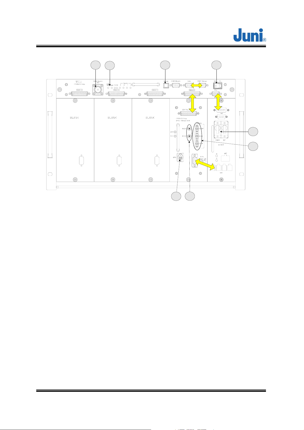
2
31 4
7
8
5
6
[Figure 2.3] Donor Hub Unit Shelf Interface
① CDMA Modem RF Port (Female N-Type): An RF cable connects the CDMA
wireless modem port on the MCU to the modem RF port situated on the outside
of the enclosure.
② MCU and SNMP reset Key: Hard reset button to restart the MCU and SNMP
agent.
③ Debug port: USB port to allow connection to any PC for debugging via the GUI
and LMT.
④ MCU Power switch: Turns the power on/off for the MCU only.
⑤ Main and battery power switch: Main power switch located on the power supply
which provides power to the entire DHU.
⑥ Monitoring port (Female SMA): Ports used to monitor signals existing within the
DHU with a spectrum analyzer or test equipment.
⑦ RF in/out port: RF ports on a single optic transceiver supports only one sector.
Version 1.17 ⓒ J
uni America Inc. Page 15 of 88
JUNI JF43-E1900/CFN03
CDMA FIBER FED REPEATER OPERATIONS MANUAL
This port is connected to the enclosure with RF cables.
⑧ Optic connector: Connector to where the fiber is connected to.
⑨
: Data and power cable
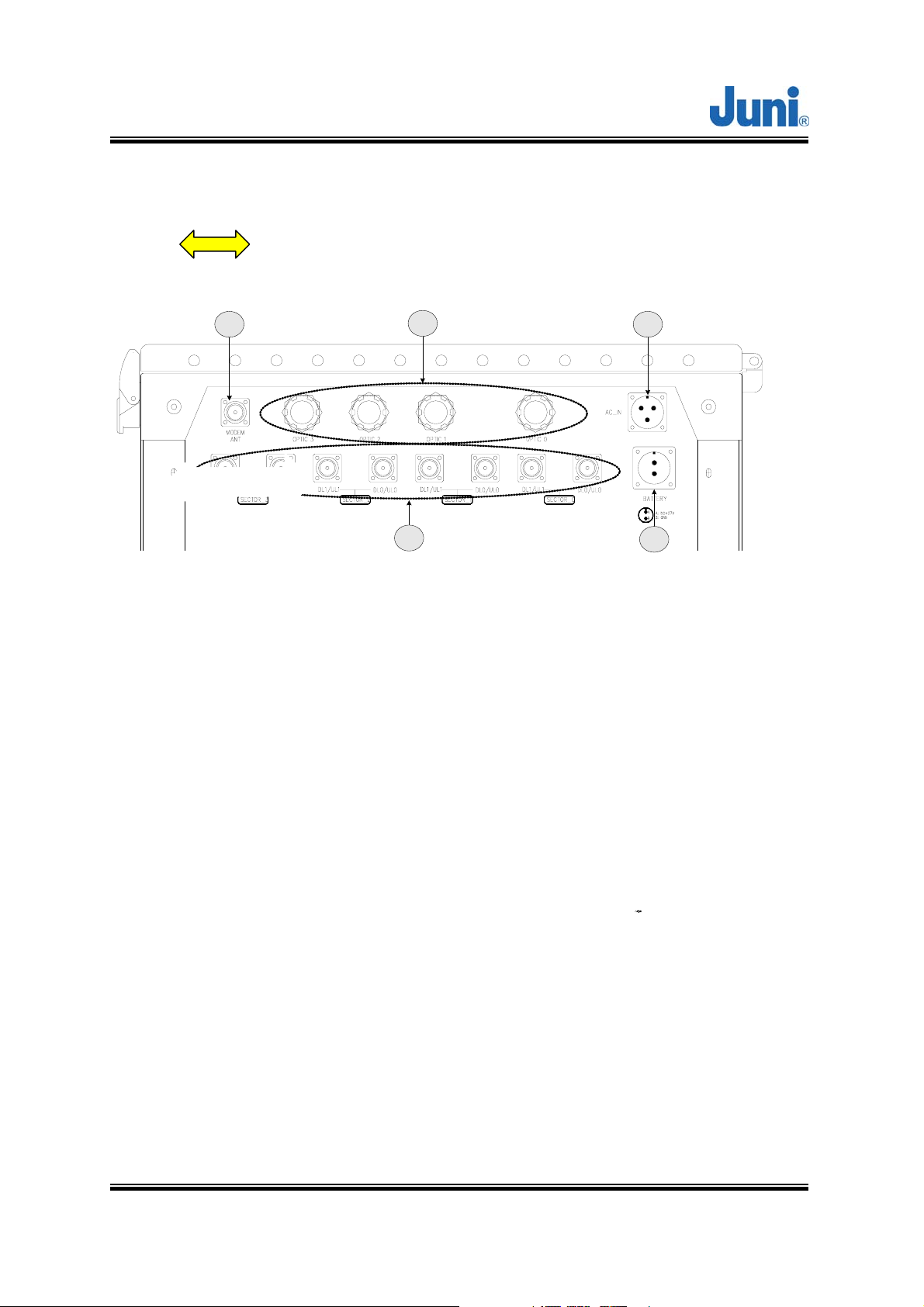
1
2
4
3
5
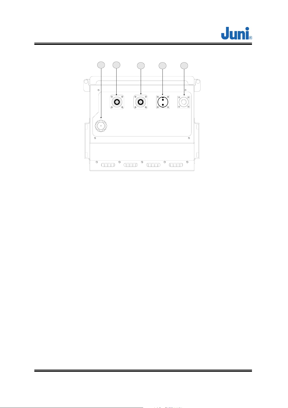
[Figure 2.4] Donor Hub Unit External Connectors (Bottom View)
① CDMA modem RF port (Female N-Type): External Antenna modem connected to
this port.
② Fiber Entrance: The fiber is passed through to connect to the optic transceiver.
③ AC power connector (Female weatherproof MS type): Connectors used for AC
powering. The AC power cable is supplied by the manufacturer.
④ RF in/out port (Female N type): Provides connection to the BTS.
⑤ Battery connector (Female weatherproof MS type): Connector for backup
batteries units.
Version 1.17 ⓒ J
uni America Inc. Page 16 of 88
JUNI JF43-E1900/CFN03
CDMA FIBER FED REPEATER OPERATIONS MANUAL
2.3 Remote Unit
This section describes the main components of the RU, the functions performed by
the components and the user interface.
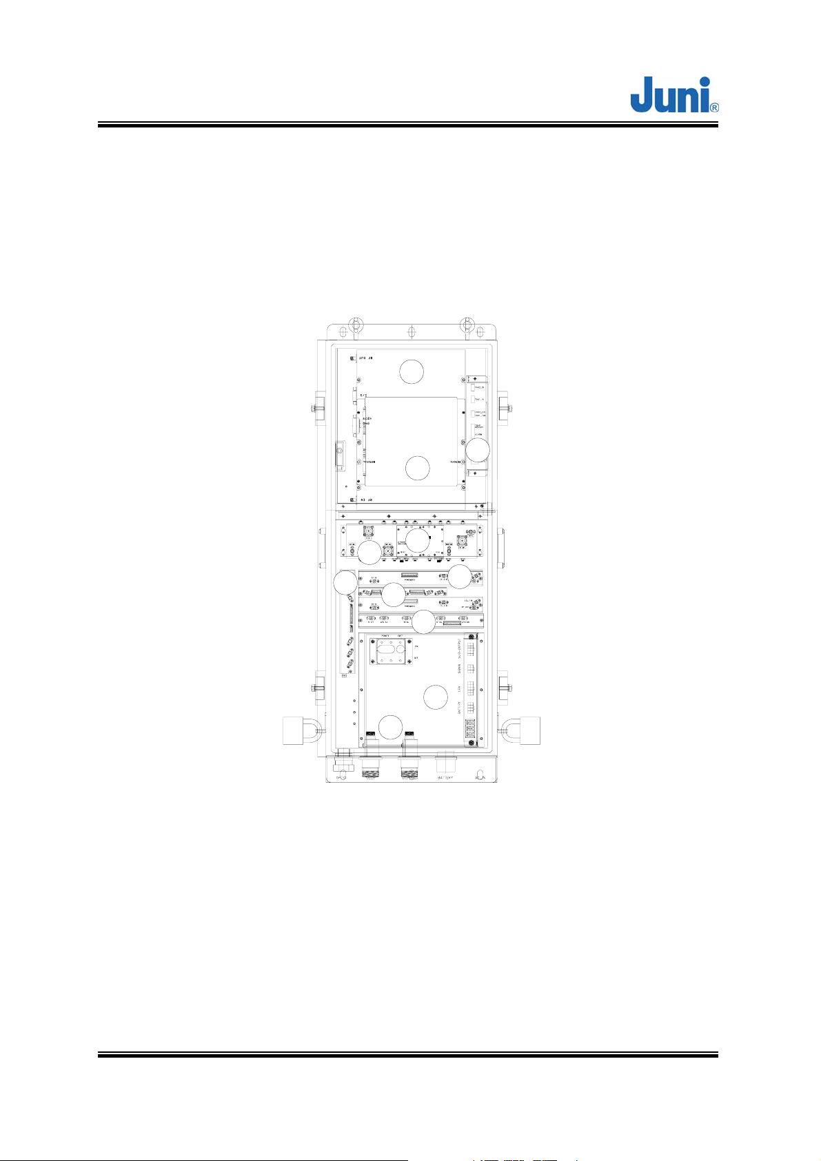
2.3.1 Remote Unit
1
2
3
4
5
RX IN
6
260 IN
NMS
520 OUT
220 OUT
NMS
TX OUT
8
7
9
10
11
[Figure 2.5] Main Components of the Remote unit
① LPA (Linear Power Amplifier): A 30Watt 6 carrier amplifier which amplifies the
signal into high output power for transmitting to the DL antenna. The amplifier is
operated by +27VDC and has a 43dB Gain.
② Control Module: Used to monitor and control the RU. Also manages the
communication with the DHU.
Version 1.17 ⓒ J
uni America Inc. Page 17 of 88

JUNI JF43-E1900/CFN03
CDMA FIBER FED REPEATER OPERATIONS MANUAL
③ FAN Controller: Turns the FAN On/Off by detecting the internal temperature of the
unit and alerting the Control module (②) the current status of the FAN .
④ Duplexer & BPF: Filters out the unwanted signals on the FWD and REV path.
⑤ Low Noise Amplifier (LNA): Performs low noise amplification on received signals.
⑥ Remote Optic Module: Converts the optic signal (from DHU) into RF signal.
Conversely, it converts the RF signal (from the RU) into an optic signal.
⑦ Remote RX SAW Module: Uses the SAW Filter to eliminate all unwanted signals
from the selected frequency and reduces the interference caused by out of band
signals.
⑧ Remote Local Module: Generates and provides the local signal required for RU
RX SAW Module (⑦).
⑨ Remote TX Drive Module: Amplifies the Forward signal and transmits to the LPA
(①), the signal is then amplified once again from the SAW Module(⑦) and
transmitted to the Optic Module(⑥). The reverse path performs down conversion of
the frequency to 1330 to 1390MHz for diversity functions.
⑩ Power Supply: Converts the input power (55 to 88VAC) into DC+27V, DC+15V, DC
+7V and supplies this power to the modules.
⑪ Arrestor: Protects the system against lightning surges. No external lightning
arrestors are required.
Version 1.17 ⓒ J
uni America Inc. Page 18 of 88
JUNI JF43-E1900/CFN03
CDMA FIBER FED REPEATER OPERATIONS MANUAL
2.3.2 Remote Unit Connectors
1 2
UL_1
OPTIC
3 4 5
DL/UL_0
BATTERY
AC_IN
[Figure 2.6] Connectors located on the bottom of the Remote Unit
① Fiber entrance port: A non metallic liquid tight strain relief is connected to the port
with a fiber core fed through the center into the RU.
② UL1 path input port: Female DIN type Diversity uplink/receive path port to connect
a second antenna
③ DL/UL0 path in/out port: Female DIN type DL/UL path port making use of a single
fiber core for full duplex operation. An antenna is connected to this port to transmit
and receive signals.
④ Battery connector: Weatherproof 2 pin MS connector used to connect an external
battery backup unit.
⑤ AC power connector: Female AC power connector to allow connection for a male
Gilbert AC power connector and CATV AC power feeder cable.
Version 1.17 ⓒ J
uni America Inc. Page 19 of 88

JUNI JF43-E1900/CFN03
CDMA FIBER FED REPEATER OPERATIONS MANUAL
2.3.3 Remote Dip Switch Settings
DIP SWITCH SECTOR DIP SWITCH SECTOR
1 2 3 4 5 6 7 8
ON
OFF
1 2 3 4 5 6 7 8
ON
OFF
1
2
1 2 3 4 5 6 7 8
ON
OFF
1 2 3 4 5 6 7 8
ON
OFF
3
4
[Table 2.1] Dip switch on the Control Unit of the Remote unit
The dip switch located on the control unit of the RU is set accordingly to the
required sector it must service. A DHU can support a maximum of four
remotes which allows the single DHU located at the BTS to service up to four
sectors.
Version 1.17 ⓒ J
uni America Inc. Page 20 of 88

JUNI JF43-E1900/CFN03
CDMA FIBER FED REPEATER OPERATIONS MANUAL
3. Installation
3.1 Transportation to the Site
During transportation of the repeater to the site, the following points need to be
considered.
• While transporting the repeater unit, it is advised to pack the repeater in its
original packaging supplied by Juni America.
• It is important to prevent any shock applied to the repeater units while
loading/unloading to/from the vehicle.
• During transportation, it is advised to prevent or minimize any movement of the
packed repeater units.
3.2 Handling of the Repeater
The user should prevent any defect caused by an accident, misuse, abuse, insect
infestations, “Acts of God”, improper installation or operation, lack of reasonable care,
unauthorized modification, and loss of parts, tampering or any repair by a person not
authorized by Juni America. As the JF43 repeater is heavy equipment, the installer
should be careful and seek assistance while attempting to lift/carry/move the units.
3.3 Installation Conditions
• Avoid direct sunlight and place the repeater in a well ventilated location.
• The environment temperature should be in a range of –20°C ∼ +55°C.
• Ground connections should be made to all metal cabinets for safety.
• Avoid any vibration.
• The VSWR of the cable which connects the repeater to the antenna should be less
than 1:1.5
Version 1.17 ⓒ J
uni America Inc. Page 21 of 88

JUNI JF43-E1900/CFN03
CDMA FIBER FED REPEATER OPERATIONS MANUAL
3.4 Inspection before Installing the Repeater
• Check if there is any physical damage on the repeater cabinet. If any damage is
found, it is advised to perform close inspection on the operating features and RF
signal test to verify repeater performance.
• Check for loose RF cables inside the repeater.
• Check whether any part of the cabinet is exposed to water or other liquid substances.
• Before installing the repeater, check the serial number of the units to be installed.
• Check all required accessories are available.
3.5 JF43 FFR Installation Procedure
3.5.1 Tools and Materials
The following tools and materials are required in order to complete the procedures in
the installation process. The installation processes include RF testing and mechanical
installation.
• Portable RF spectrum analyzer or RF power meter
• RF Signal generator
• AC/DC voltmeter
• RF adaptors
• External attenuators
• RF test cables
• PC with Local Maintenance Terminal (LMT) software installed
• USB-A to USB-B interface cable
• 99% pure alcohol
• Contraction tubes
• Optical TDR (Time Domain Reflectometer)
• Wireless terminal
• Pencil or pen
• Writing pad
Version 1.17 ⓒ J
uni America Inc. Page 22 of 88

JUNI JF43-E1900/CFN03
CDMA FIBER FED REPEATER OPERATIONS MANUAL
3.5.2 Cautions during Installation
1. Caution when connecting the optic cable:
● Clean the connection part of connector using an industrial tissue and 99.9% pure
alcohol.
● After connecting the optic jumper cable, the residual section should be set in a
large circular form to prevent it from folding.
2. Caution when setting the repeater :
● Do not power on the system while the output port of the system is not connected.
● Before connecting the DHU input from the BTS, measure and confirm the DHU
input level is within the DHU input dynamic range.
● Confirm the connections of the cables and connectors are tight.
● Confirm the ground connection complies with the safety specifications for
protection against thunderstorms.
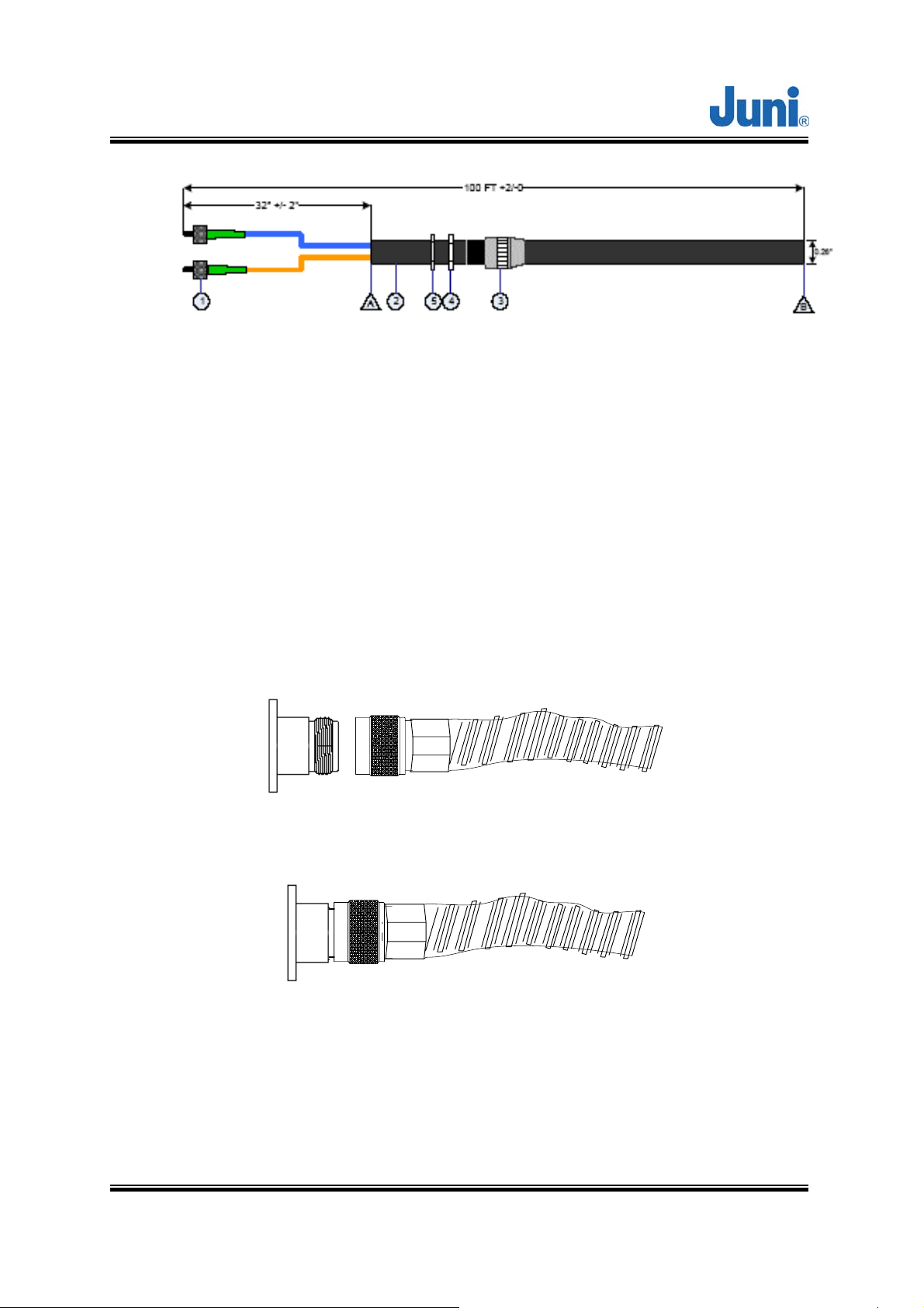
3.5.3 Optical Fiber Jumper Cable Assembly
An Optical Fiber Jumper Cable assembly is available from Juni America, Inc. to
facilitate connection from a single-mode optical fiber transmission facility (dark fiber)
to the DHU or RU. The Optical Fiber Jumper Cable assembly is shown in the figure
below. It has an overall length of approximately 100 feet. It includes a weatherproof
“boot” assembly which serves to seal the circular opening (in the DHU or RU), where
the optical fiber jumper cable enters and connects to the FFR subsystem, via the
FC/APC connector provided.
Only one optical fiber core is required for the optical fiber connection between the
DHU and RU, and a second optical fiber core is provided within the jumper cable
assembly as a “spare”. Should one of the fiber cores fail, ensure the system is turned
off by following the “Replacement of faulty units” section. Unplug the problematic fiber
core from the DHU and RU and plug the spare jumper cable into the unit. This will
only work provided the spare fiber is functioning.
Version 1.17 ⓒ J
uni America Inc. Page 23 of 88
JUNI JF43-E1900/CFN03
CDMA FIBER FED REPEATER OPERATIONS MANUAL
[Figure 3.1] Optical Fiber Jumper Cable
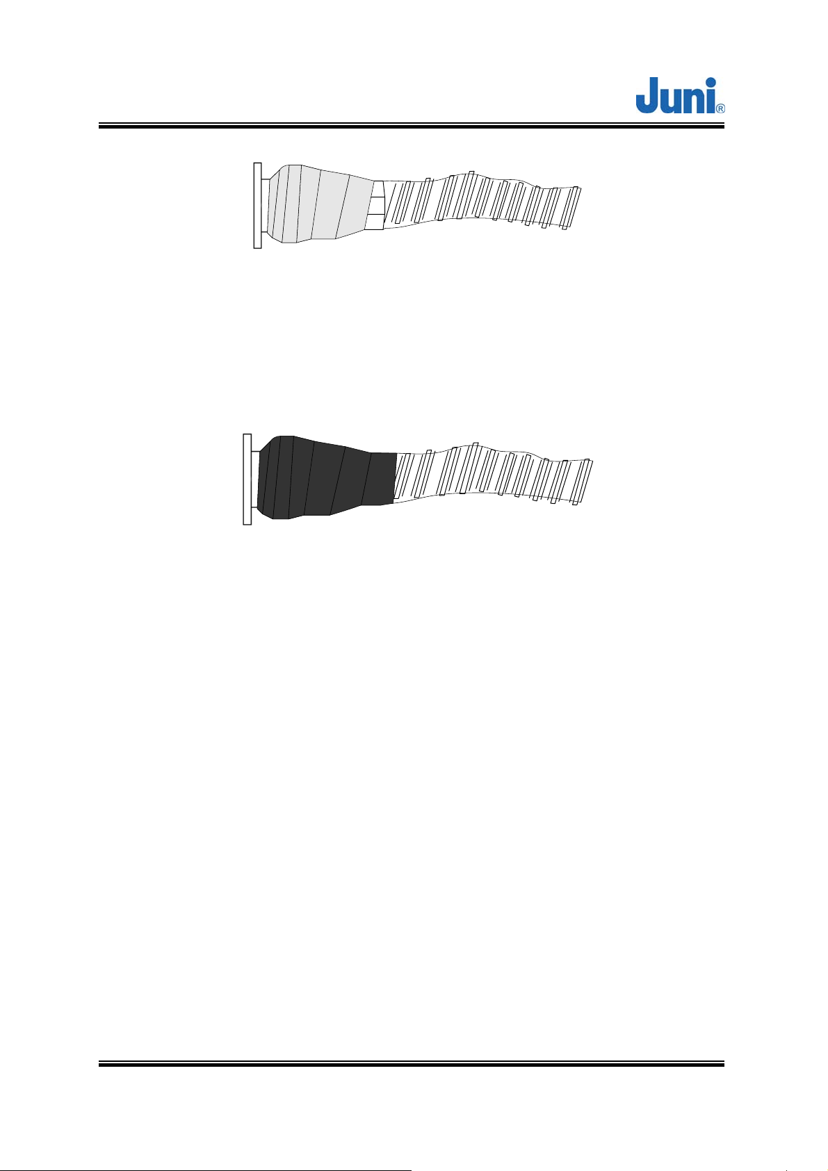
3.5.4 Weatherproofing Connectors
Once all connectors and cables have been configured and assembled,
weatherproofing is vital to prevent corrosion due to water ingress which could lead to
eventual failure.
1. Making sure that the connector surfaces are clear of residue and dry, firmly
tighten the connectors.
[Figure 3.2] Connect cable to connector
[Figure 3.3] Fasten cable to connector
2. Seal the connector assembly by tightly wrapping Butyl tape over the connection.
Two or more layers should be used so that the tape seals the entire connection
and extends beyond the connector by about an inch.
Version 1.17 ⓒ J
uni America Inc. Page 24 of 88
JUNI JF43-E1900/CFN03
CDMA FIBER FED REPEATER OPERATIONS MANUAL
[Figure 3.4] Wrap connection with Butyl tape
3. Tightly wrap electrical tape around the existing Butyl tape making sure to also
extend one inch beyond the Butyl tape to completely envelop the tape and
connector.
[Figure 3.5] Wrap over Butyl tape with electric tape
3.5.5 Donor Unit Eye Bolts
There are four captive eye bolt tapped holes located at the top of the DHU as shown
below. The length of the tapped hole is 0.97 inches or 25mm. The customer supplied
¼” 20UNC eye bolts may be used to assist in hoisting the DHU above the ground for
wall or pole mount solutions.
Ensure that the eyebolts are securely attached to the top of the DHU. Check that the
cables used to lift the DHU is securely fastened to the eyebolts before it is lifted.
Version 1.17 ⓒ J
uni America Inc. Page 25 of 88
JUNI JF43-E1900/CFN03
CDMA FIBER FED REPEATER OPERATIONS MANUAL
[Figure 3.6] Donor Unit Eye Bolt Patterns
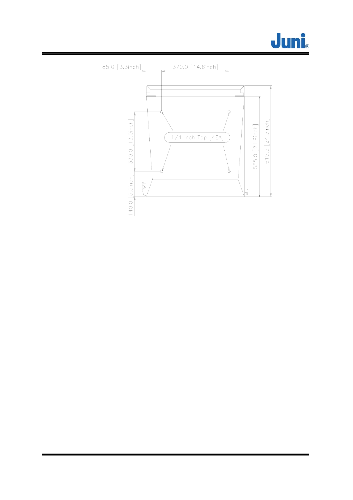
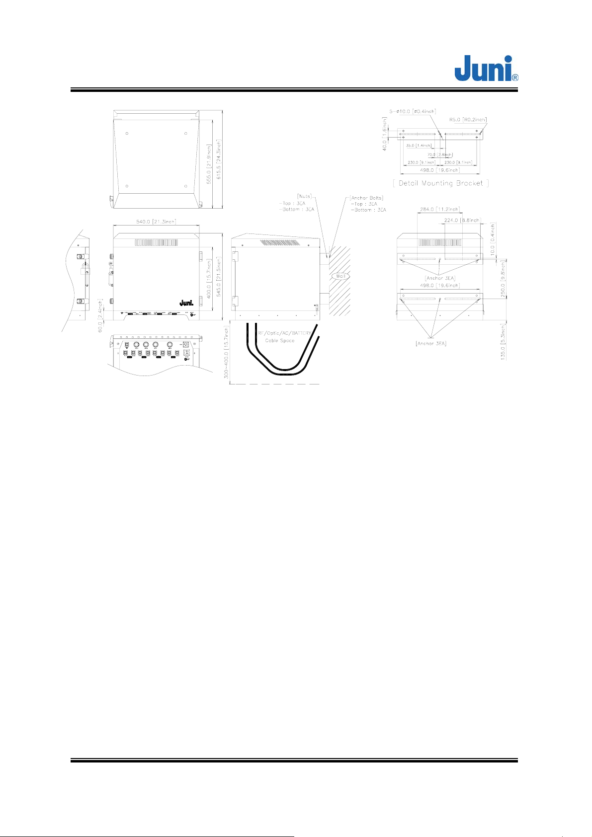
3.5.6 Donor Unit Standard Wall Mount Guide
The DHU is capable of being wall mounted. There are two horizontal panels
protruding slightly behind the DHU, with holes along the panel to allow bolts and nuts
to be fastened. The wall mount holes will accommodate bolt diameters up to a
maximum of 0.4 inches. Drill holes in the wall or area in which it is to be installed to
match the mounting holes on the panels.
Attach the DHU to the wall using the appropriate fastening method.
The figure below displays the positioning and size of the wall mount holes.
Version 1.17 ⓒ J
uni America Inc. Page 26 of 88
JUNI JF43-E1900/CFN03
CDMA FIBER FED REPEATER OPERATIONS MANUAL
[Figure 3.7] Donor Hub Unit Wall Mounting
3.5.7 Donor Hub Unit Commissioning and Provisioning
1. Verify that the power is switched OFF.
2. Before any other connections are made, ensure that the ground terminal on the DHU
cabinet has been connected to the common ground of the installation site, as
described in the previous section.
3. Using a DC voltmeter, verify that the DC voltage level at the power terminals is a
nominal ±24 VDC. The DC power provided to the Donor can be either polarity.
4. Connect a customer-supplied power cable to the DHU Enclosure.
5. Connect a customer-supplied AC power cable to the front of the DHU power supply
when the DHU enclosure is not used.
6. Connect a customer-supplied Optical Fiber cable to the Optic port of the DHU, inside
the Enclosure.
7. Connect a customer supplied modem antenna to the RF modem port on the bottom
of the DHU unit.
8. Turn the power on with the main switch located on the PSU and then power on the
Version 1.17 ⓒ J
uni America Inc. Page 27 of 88
 Loading...