

Page 1

1
OPERATING INSTRUCTIONS
TL
-
1705W
17.1 inch WIDESCREEN TFT-LCD TV
Page 2
2
Introduction
READ THIS BEFORE OPERA TING YOUR UNIT
: TO REDUCE THE RISK OF
ELECTRIC SHOCK, DO NOT
REMOVE COVER (OR BACK). NO
USER-SERVICEABLE PARTS
INSIDE. REFER SERVICING TO
QUALIFIED SERVICE PERSONNEL.
: TO REDUCE THE RISK OF FIRE OR ELECTRIC SHOCK,
DO NOT EXPOSE THIS APPLIANCE TO RAIN OR MOISTURE.
CAUTION
WARNING
This symbol is intended to alert the user to the
presence of uninsulated "dangerous voltage"
within the product's enclosure that may be of
sufficient magnitude to constitute a risk of
electric shock to persons.
This symbol is intended to alert the user to the
presence of important operating and
maintenance (servicing) instructions in the
literature accompanying the appliance.
Units shipped to the U.S.A and Canada are designed for operation on 120 V AC only.
Safety precaution with use of a polarized AC plug.
However, some products may be supplied with a nonpolarized plug.
FOR YOUR SAFETY
U.S.A
CANADA
120 V
Note to CATV System Installer :
This reminder is provided to call the CATV system installer’s attention to Article
820-40 of the NEC that provides guidelines for proper grounding and, in
particular, specifies that the cable ground shall be connected to the grounding
system of the building, as close to the point of cable entry as pracitcal.
FCC INFORMATION
: To prevent electric shock, match wide blade of plug to wide slot, fully
insert.
: Pour éviter chocs électriques, introduire la lame la plus large de la
fiche dans la borne correspondante de la prise et pousser jusqu’ au
fond.
CAUTION
ATTENTION
NOTE: THE MANUFACTURER IS NOT RESPONSIBLE FOR ANY RADIO OR TV
INTERFERENCE CAUSED BY UNAUTHORIZED MODIFCATIONS TO THIS
EQUIPMENT. SUCH MODIFICATIONS COULD VOID THE USER’S AUTHORITY TO
OPERATE THE EQUIPMENT.
NOTE: This equipment has been tested and found to comply with the limits for a Class
B digital device, pursuant to Part 15 of the FCC Rules. These limits are designed to
provide reasonable protection against harmful interference in a residential installation.
This equipment generates, uses and can radiate radio frequency energy and, if not
installed and used in accordance with the instructions, may cause harmful interference
to radio communications. However, there is no guarantee that interference will not
occur in a particular installation. If this equipment does cause harmful interference to
radio or television reception, which can be determined by turning the equipment off
and on, the user is encouraged to try to correct the interference by one or more of the
following measures:
Reorient or relocate the receiving antenna.
Increase the separation between the equipment and receiver.
Connect the equipment into an outlet on a circuit different from that to which the
receiver is connected.
Consult the dealer or an experienced radio/TV technician for help.
Caution : Any changes or modifications in construction of this device which are not expressly
approved by the party responsible for compliance could void the user’s authority to
operate the equipment.
Page 3
3
1. Read Instructions - All the safety and operating instructions should
be read before the product is operated.
2. Retain instructions - The safety and operating instructions should
be retained for future reference.
3. Heed Warnings - All warnings on the product and in the operating
instructions should be adhered to.
4. Follow Insturctions - All operating and use instuctions should be
followed.
5. Cleaning - Unplug this product from the wall outlet before cleaning.
Do not use liquid cleaners or aerosol cleaners. Use a damp cloth for
cleaning.
6. Attachments - Do not use attachments not recommended by the
product manufacturer as they may cause hazards.
7. Water and Moisture - Do not use this product near water - for
example, near a bath tub, wash bowl, kitchen sink, or laundry tub; in
a wet basement, or near a swimming pool; and the like.
8. Accessories - Do not place this product on an unstable cart, stand,
tripod, bracket, or table. The product may fall, causing serious injury
to a child or adult, and serious damage to the product. Use only with
a cart, stand, tripod, bracket, or table recommended by the
manufacturer, or sold with the product. Any mounting of the product
should follow the manufacturer’s insturctions, and should use a
mounting accessory recommended by the manufacturer.
9. A product and cart combinaion should be moved with care. Quick
stops, excessive force, and uneven surfaces may cause the product
and cart combination to overturn.
10. Ventilation - Slots and openings in
the cabinet are provided for
ventilation and to ensure reliable
operation of the product and to
protect it from overheating, and
these openings must not be
blocked or covered. The openings
should never be blocked by placing
the product on a bed, sofa, rug, or other similar surface. This
product should not be placed in a built-in installation such as a
bookcase or rack unless proper ventilation is provided or the
manufacturer’s intructions have been adhered to.
11. Power Sources - This product should be operated only from the
type of power source indicated on the marking label. If you are not
sure of the type of power supply to your home, consult your product
dealer or local power company. For porducts intended to operate
from battery power, or other sources, refer to the operating
instructions.
12. Grounding or Polarization - This product may be equipped with a
polarized alternating-current line plug (a plug having one blade
wider than the other). This plug will fit into the power outlet only one
way. This is a safety feature. If you are unable to insert the plug
fully into the outlet, try reversing the plug. If the plug should still fail
to fit, contact your electrician to replae your obsolete outlet. Do not
defeat the safety purpose of the polarized plug.
Alternate Warnings - This product is equipped with a three-wire
grounding-type plug, a plug having a third(grounding) pin. This plug
will only fit into a grounding-type power outlet. this is a safety
feature. If you are unable to insert the plug into the outlet, contact
your electrician to replace your obsolete outlet. Do not defeat the
safety purpose of the gronding-type plug.
13. Power-Cord Protection - Power-supply cords should be routed so
that they are not likely to be walked on or pinched by items placed
upon or against them, paying particlar attention to cords at plugs,
convenience receptacles, and the point where they exit from the
product.
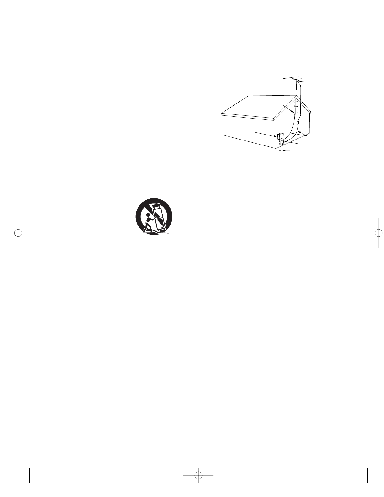
14. Outdoor Antenna Grounding - If an outside antenna or cable
system is connected to the product, be sure the antenna or cable
system is grounded so as to provide some protection against
voltage surges and built-up static charges. Article 810 of the
National Electrical Code, ANSI/NFPA 70, provides information with
regard to proper grounding of the mast and supporting structure,
grounding of the lead-in wire to an antenna discharge unit, size of
grounding conductors, location of antenna-discharge unit,
connection to grounding electrodes, and requirements for the
grounding electrode. See Figure 1.
15. Lightning - For added protection for this product during a lightning
storm, or when it is left unattended and unused for long periods of
time, unplug it from the wall outlet and disconnect the antenna or
cable system. This will prevent damage to the product due to
lightning and power-line surges.
16. Power Lines - An outside antenna system should not be located in
the vicinity of overhead power lines or other electric light or power
circuits, or where it can fall into such power lines or circuits. When
installing an outside antenna system, extreme care should be taken
to keep from touching such power lines or circuits as contact with
them might be fatal.
17. Overloading - Do not overload wall outlets, extension cords, or
integral convenience receptacles as this can result in a risk of fire
or electric shock.
18. Object and Liquid Entry - Never push objects of any kind into this
product through openings as they may touch dangerous voltage
points or short-out parts that could result in a fire or electric shock.
Never spill liquid of any kind on the product.
19. Servicing - Do not attempt to service this product yourself as
opening or removing covers may expose you to dangerous voltage
or other hazards. Refer all servicing to qualified service personnel.
20. Damage Requiring Service - Unplug this product form the wall
outlet and refer servicing to qualified service personnel under the
following conditions:
a) When the power-supply cord or plug is damaged,
b) If liquid has been spilled, or objects have fallen into the
product,
c) If the product has been exposed to rain or water,
d) If the product does not operate normally by following the
operating instructions. Adjust only those controls that are
covered by the operating instructions as an improper
adjustment of other controls may result in damage and will
often require extensive work by a qualified technician to
restore the product to its normal operation.
e) If the product has been dropped or damaged in any way, and
f) When the product exhibits a distinct change in performance -
this indicates a need for service.
21. Replacement Parts - When replacement parts are required, be
sure the service technician has used replacement parts specified
by the manufacturer or have the same characteristics as the
original part. Unauthorized substitutions may result in fire, electric
shock, or other hazards.
22. Safety Check - Upon completion of any service or repairs to this
product, ask the service technician to perform safety checks to
determine that the product is in proper operating condition.
23. Wall or Ceiling Mounting - The product should be mounted to a
wall or ceiling only as recommended by the manufacturer.
24. Heat - The product should be situated away from heat sources
such as radiators, heat registers, stoves, or other products
(including amplifiers) that produce heat.
PORTABLE CART WARNING
Figure 1
Example of antenna grounding as per
National Electrical Code, ANSI/NFPA 70
SAFETY INSTRUCTIONS
GROUND
CLAMP
ELECTRIC
SERVICE
EQUIPMENT
GROUND CLAMPS
POWER SERVICE GROUNDING
ELECRODE SYSTEM
NEC-NATIONAL ELECTRICAL CODE
(NEC ART 250, PART H)
ANTENNA
LEAD IN
WIRE
ANTENNA
DISCHARGE UNIT
(NEC SECTION 810-20)
GROUNDING CONDUCTORS
(NEC SECTION 810-21)
Page 4

CONTENTS
4
Controls
Introduction
Installations
Operations
PC Display
Troubleshooting
READ THIS BEFORE OPERATING YOUR UNIT | 2
SAFETY INSTRUCTIONS | 3
FRONT OF THE TV | 5
REAR OF THE TV | 6
REMOTE CONTROL | 7
USING YOUR TV AS A COMPUTER(PC) DISPLAY | 60
| 63
| 66
Appendix
Specifications
RETRACTABLE STAND | 64
CLEANING AND MAINTAINING YOUR TV | 64
USING YOUR TV IN ANOTHER COUNTRY | 65
CONNECTING VHF AND UHF ANTENNAS | 8
CONNECTING CABLE TV | 9
CONNECTING VCR | 11
CONNECTING A S-VHS VCR | 13
CONNECTING DVD PLAYER | 13
CONNECTING DTV(SET-TOP BOX) | 14
CONNECTING POWER DC INPUT | 14
INSTALLING BATTERIES IN THE REMOTE CONTROL | 15
TURNING THE POWER ON/OFF | 16
VIEWING THE MENU | 16
SETTING THE OSD TIMEOUT | 17
SELECTING A MENU LANGUAGE | 18
SELECTING INPUT SOURCE | 19
ADJUSTING THE VOLUME | 22
LISTENING WITH HEADPHONES | 23
MEMORIZING THE CHANNELS | 24
CHANGING CHANNELS | 27
CUSTOMIZING THE PICTURE | 29
USING AUTOMATIC PICTURE SETTINGS | 30
CHANGING THE SCREEN SIZE | 30
CHANGING THE SCREEN POSITION | 30
VIEWING THE CURRENT STATUS | 31
CUSTOMIZING THE SOUND | 32
SELECTING A SURROUND SOUND | 33
Special Features
SELECTING THE BACKGROUND OF MENU | 34
FINE TUNNING CHANNELS | 34
LABELING THE CHANNEL NAME | 35
FREEZING THE PICTURE | 36
DIGITAL PAN AND ZOOM | 37
CHOOSING A MULTI-CHANNEL SOUND (MTS) SOUNDTRACK | 39
SETTING THE CLOCK | 40
SETTING THE ON/OFF TIMER | 41
SETTING THE SLEEP TIMER | 44
ADJUSTING CLOSED CAPTION SETTINGS | 45
VIEWING CLOSED CAPTIONS | 47
CHANGING WINDOW LAYOUT | 48
VIEWING VARIOUS SOURCES SIMULTANEOUSLY | 48
BLOCKING THE CONTENTS | 53
CHILD LOCK | 58
FACTORY RESET | 59
Page 5
Controls
5
CH VOL.
MENU SOURCE
1 2 3 4 5
8
6
7
STANDBY/ON
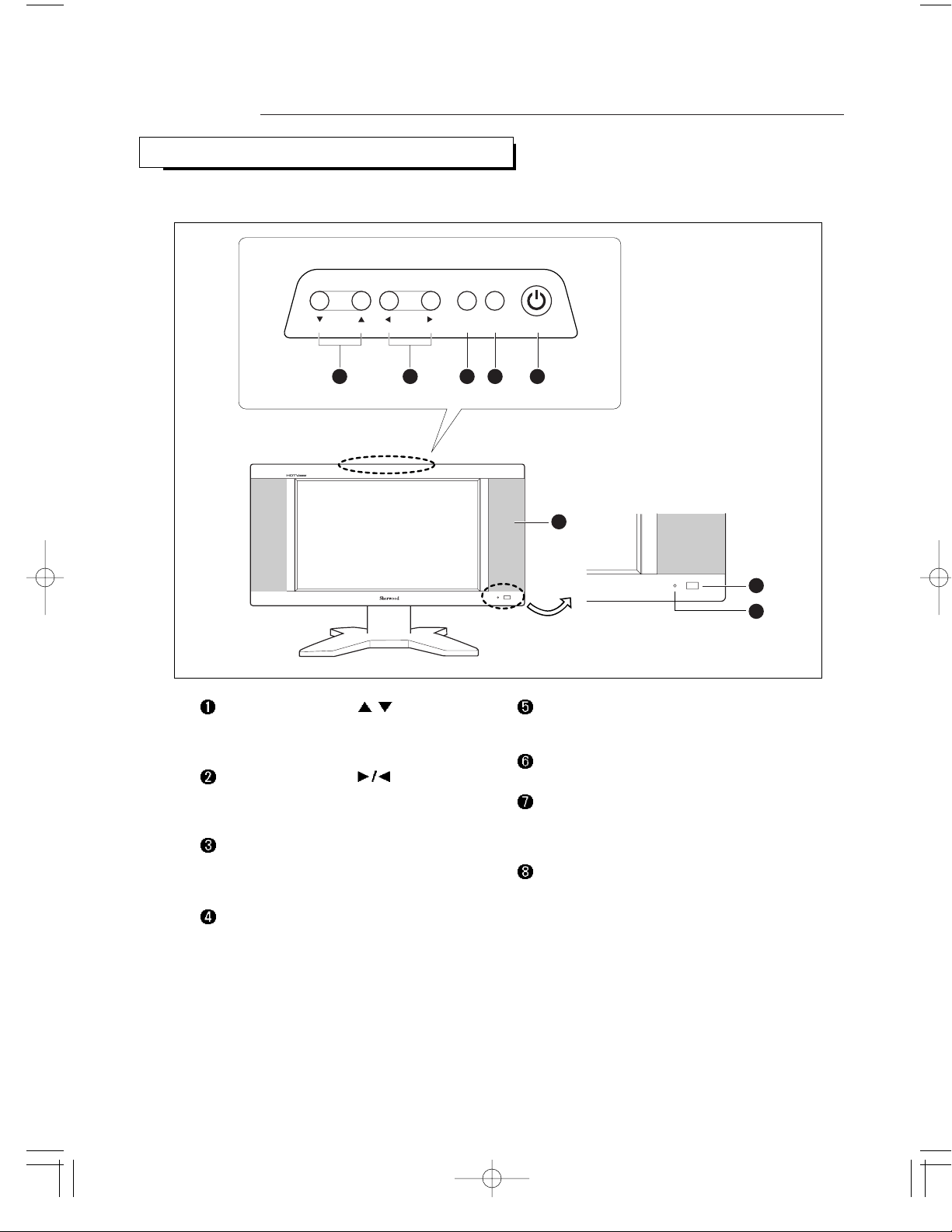
FRONT OF THE TV
CHANNEL UP/DOWN (
/ )
Press to change channels. Also press to highlight
various items on the on-screen menu.
VOLUME UP/DOWN (
)
Press to increase or decrease the volume. Also
used to select items on the on-screen menu.
MENU
Press to see an on-screen menu of your TV’s
features.
SOURCE
Press to select input source.
STANDBY/ON
Press to turn the TV on and off.
SPEAKER
Remote Control Sensor
Aim the remote control towards this square on
the TV.
STANDBY indicator
Lights up red when you turn the power off.
The buttons on the front panel control our TV’s basic features, including the on-screen menu. To use the more
advanced features, you must use the remote control.
Page 6

REAR OF THE TV
6
1 2 3 4 5 7 9 1086
--
--
POWER (DC) INPUT
PC VIDEO INPUT
Connect to the video output port on your PC.
PC AUDIO INPUT
Connect to the audio output jacks on your PC.
S-VIDEO INPUT
Connect to the S-Video jack of a VCR or
camcorder, etc.
COMPOSITE VIDEO INPUT
Connect to the composite(normal) video jack of a
VCR or camcorder, etc.
AUDIO INPUT
Connect to the audio jack of a VCR or
camcorder, etc.
COMPONENT(DVD/DTV) VIDEO INPUT
Connect to the component video jacks of a DVD
player or a Set-Top Box.
COMPONENT(DVD/DTV) AUDIO INPUT
Connect to the audio jacks of a DVD player or a
Set-Top Box.
HEADPHONE JACK
Connect a set of external headphones to this jack
for private listening.
ANTENNA INPUT
Connect to an antenna or a cable TV system.
For more information on connecting equipment, see "Installations" on page 8 and "USING YOUR TV AS A
COMPUTER(PC) DISPLAY" on page 60.
Page 7
7
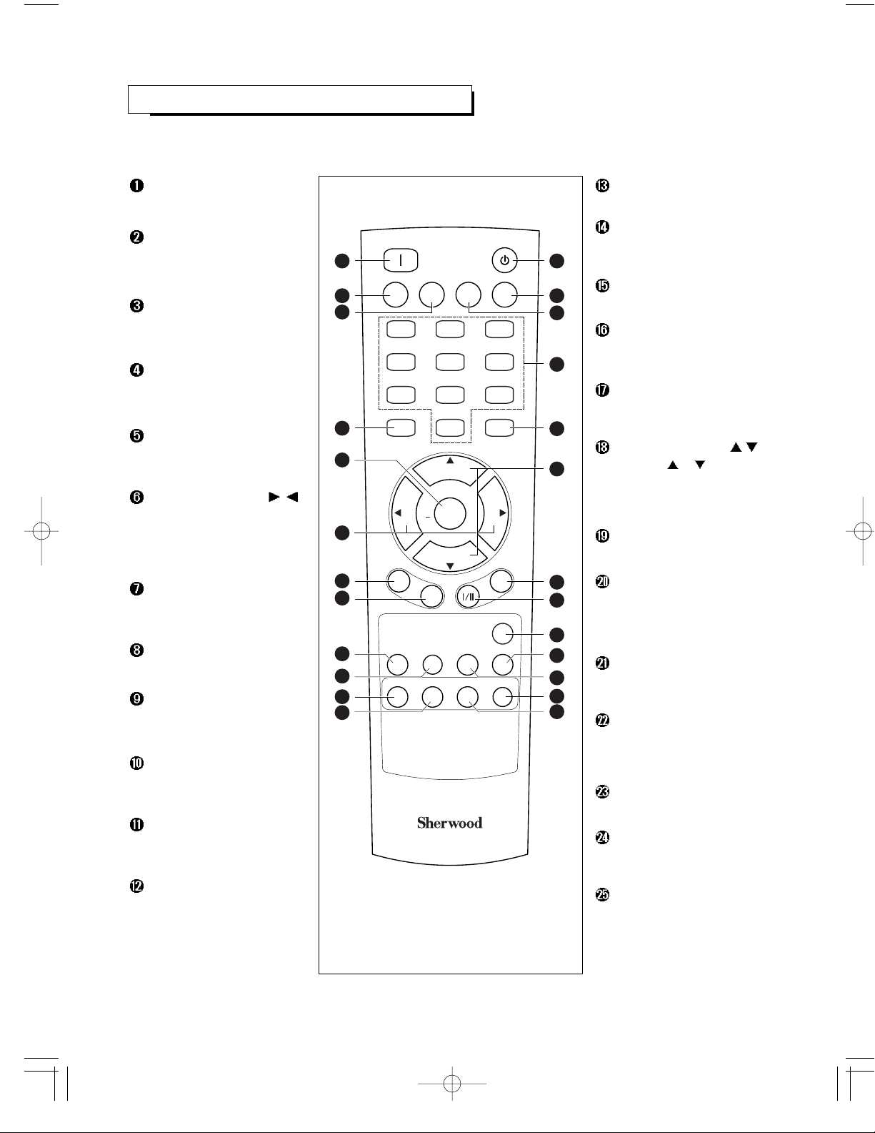
All the functions can be controlled with this remote control unit.
Some functions can also be adjusted with the buttons on the front panel of the set.
REMOTE CONTROL
POWER ON
Turns the TV on.
PC AUTO
Press to center the screen
automatically in PC mode.
SLEEP
Press to select a preset time
interval for automatic shutoff.
MENU
Displays the main on-screen
menu.
ENTER
Press to display current status
or enter into certain sub menu.
VOLUME UP/DOWN ( / )
Press to increase or decrease
the volume. (Also used to make
selections on the on-screen
menu.)
P.MODE (Picture Mode)
Press to select the preferred
picture setting.
P.SIZE (Picture Size)
Press to change the screen size .
CHILD LOCK
Press to lock the controlling TV
with buttons on the top panel.
ADD/ERASE
Press to add or erase channels
in the TV’s memory.
WINDOW SEL.
Press to select the one of the
window in each PIP mode.
PIP (Picture in Picture)
Each time this button is
pressed, the window layout is
changed.
POWER ONPOWER ON
PC AUTOPC AUTO
ENTERENTER
VOLVOL VOLVOL
CHILDCHILD
LOCKLOCK
WINDOWWINDOW
SEL.SEL.
PIPPIP SWSWAPAP SRCSRC
ADD/ADD/
ERASEERASE CAPTIONCAPTION STILLSTILL
1 2 3
4 5 6
7 8
0
9
SLEEPSLEEP PRE.CHPRE.CH AUTOSETAUTOSET
MENUMENU MUTEMUTE
SOURCESOURCE
STSTANDBYANDBY
C
H
+
C
H
-
P
.
M
O
D
E
P
.
S
I
Z
E
M
T
S
S
U
R
R
.
+
REMOTE CONTROL RM-501
25
24
23
22
21
20
19
18
17
16
15
14
131
2
3
4
5
6
7
8
9
10
11
12
STANDBY
Turns the TV off.
AUTOSET
Press to memorize the receptable
channels automatically.
PRE. CH (Previous Channel)
Tunes to the previous channel.
NUMBER BUTTONS
Press to select channels
directly on the TV.
MUTE
Press to temporarily cut off the
sound.
CHANNEL UP/DOWN (
/ )
Press CH or to change
channels. (Also used to
highlight the items on the onscreen menus.)
SURROUND
Press to enjoy surround sound.
MTS I/II
(Multichannel Television Sound)
Press to choose stereo, mono
or Seperate Audio
Program(SAP broadcast).
SOURCE
Press to select input signal
source.
STILL
Press to stop the action at a
particular scene. Press again to
resume normal video.
CAPTION
Controls the caption decoder.
SRC
Press to select the input source
for the sub picture in PIP mode.
SWAP
Exchanges the two video
signals that is currently
displayed on the screen in the
DW(Double Window) mode.
Page 8
Plug the antenna lead into the TV antenna terminal on
the rear panel.
CONNECTING VHF AND UHF ANTENNAS
Installations
8
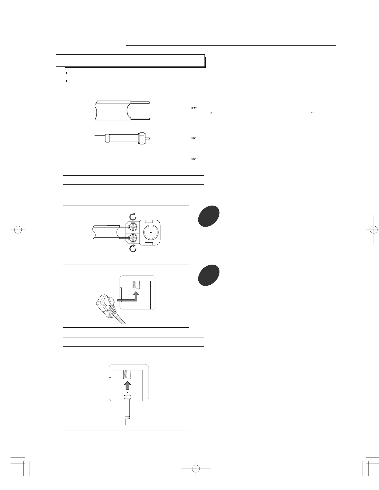
Antennas with 300-ohm Flat Twin Leads
Antennas with 75-ohm Round Leads
If your antenna has a set of leads that look like this,
see
Antennas with 300-ohm Flat Twin Leads
below.
If your antenna has one lead that looks like this, see
“Antennas with 75-ohm Round Leads” below.
If you have two antennas, see “Separate VHF and
UHF Antennas”, on page 9.
If you are using an off-air antenna antenna (such as a roof antenna or “rabbit ears”) that has 300-ohm twin
flat leads, follow the directions below.
1
Place the wires from the twin leads under
the screws on a 300-75 ohm adaptor (not
supplied). Use a screwdriver to tighten the
screws.
TV
ANTENNA
TV
ANTENNA
2
Plug the adaptor into the TV antenna
terminal on the rear panel.
Please be certain that TV is unplugged from the AC outlet before making any connections.
Since different component often have different terminal names, carefully read the operating instructions of the
component connected.
Page 9

9
Separate VHF and UHF Antennas
Cable without a Cable Box
Connecting to a Cable Box that Descrambles All Channels
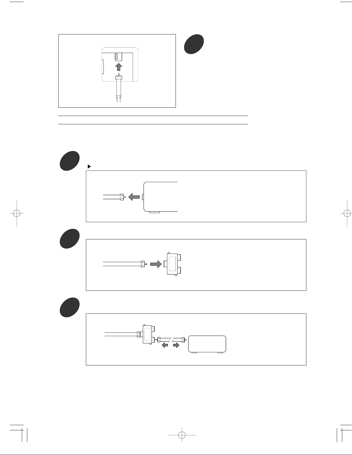
If you have two separate antennas for your TV (one VHF and one UHF), you must combine the two antenna
signals before connecting the antennas to the TV. This procedure requires an optional combiner-adaptor
(available at most electronics shops).
UHF
VHF
1
Connect both antenna leads to the
combiner.
ANTENNA
OUT
ANTENNA
IN
1
Find the cable that is connected to the
ANTENNA OUT terminal on your cable box.
TV
ANTENNA
UHF
VHF
2
Plug the combiner into the TV antenna
terminal on the rear panel.
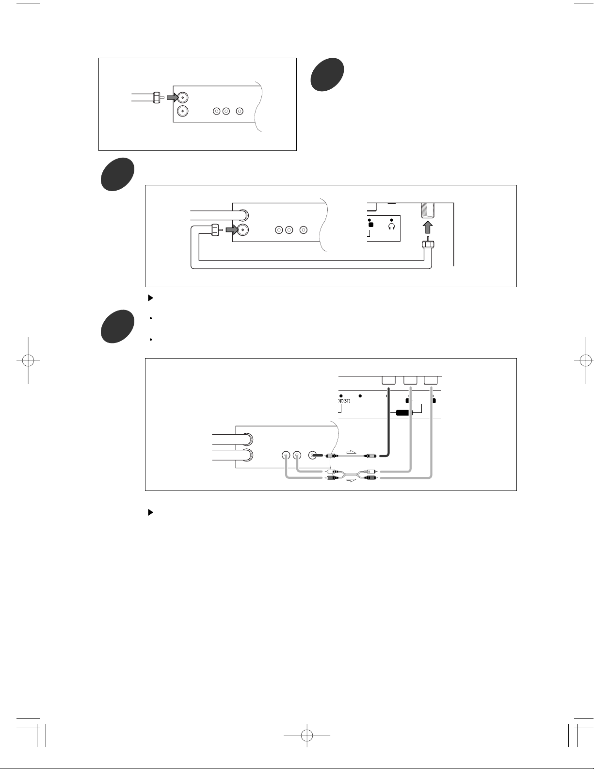
CONNECTING CABLE TV
To connect to a cable TV system, follow the instructions below.
Plug the incoming cable into the TV antenna terminal
on the rear panel.
TV
ANTENNA
Because this TV is cable-ready, you do not need a
cable box to view unscrambled cable channels.
This terminal might be labeled “ANT OUT”, “VHF
OUT”, or simply, “OUT”.
Page 10
10
TV
ANTENNA
2
Connect the other end of this cable to the
TV antenna terminal on the rear panel.
Connecting to a Cable Box that Descrambles Some Channels
If your cable box descrambles only some channels (such as premium channels), follow the instructions below. You will
need a two-way splitter, an RF(A/B) switch, and four lengths of coaxial cable. (These items are available at most
electronics stores.)
ANTENNA
IN
Incoming
Cable
Splitter
IN
CABLE OUT
Cable Box
Incoming
Cable
Splitter
1
Find and disconnect the cable that is connected to the ANTENNA IN terminal on your cable box.
2
Connect this cable to a two-way splitter.
3
Connect a coaxial cable between an OUTPUT terminal on the splitter and the IN terminal on the
cable box.
This terminal might be labeled “ANT IN”, “VHF IN”, or simply “IN”.
Page 11

11
IN
CABLE OUT
Cable Box
Incoming
Cable
Splitter
A
B
RF (A/B)
Switch
4
Connect a coaxial cable between the ANTENNA OUT terminal on the cable box and the B-IN
terminal on the A/B switch.
IN
CABLE OUT
Cable Box
Incoming
Cable
Splitter
A
B
RF (A/B)
Switch
5
Connect another cable between the other OUT terminal on the splitter and the A-IN terminal on
the RF(A/B) switch.
IN
CABLE OUT
Cable Box
Incoming
Cable
Splitter
TV
ANTENNA
A
B
RF (A/B)
Switch
6
Connect the last coaxial cable between the OUT terminal on the RF(A/B) switch and the VHF/UHF
terminal to the TV antenna terminal on the rear panel.
After you’ve made this connection, set the A/B switch to the “A” position for normal viewing. Set
the A/B switch to the “B” position to view scrambled channels. (When you set the A/B switch to
“B”, you will need to tune your TV to the cable box’s output channel, which is usually channel 3 or
4.)
CONNECTING VCR
These instructions assume that you have already connected your TV to an antenna or a cable TV system (according to the
instructions on pages 8 - 9). Skip step 1 if you have not yet connected to an antenna or a cable system.
TV
ANTENNA
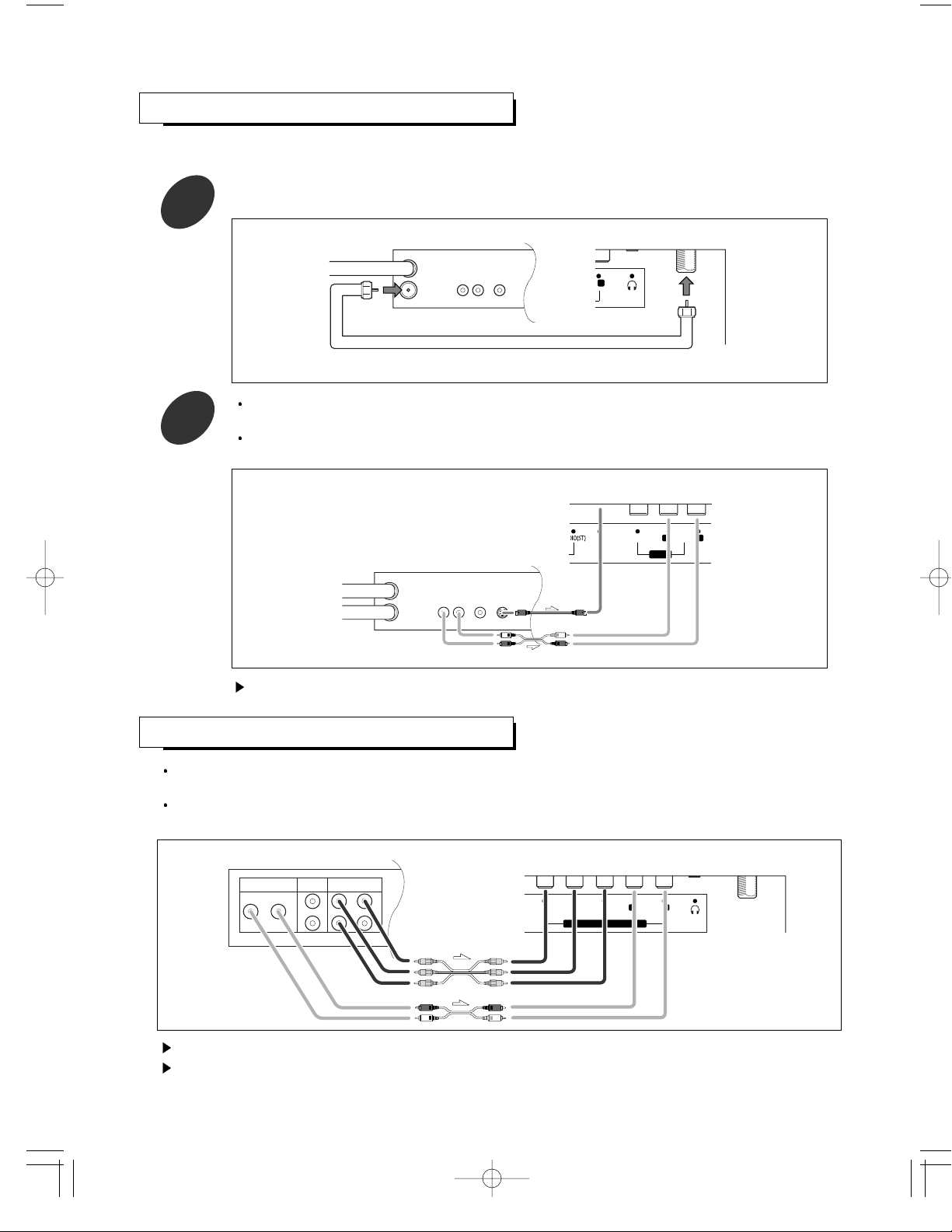
1
Unplug the cable or antenna from the rear
of the TV.
Page 12
12
IN
OUT
AUDIO
OUT
LR
VIDEO
OUT
ANTENNA
VCR Rear Panel
Incoming
Cable or
Antenna
2
Connect the cable or antenna to the
ANTENNA IN terminal on the rear of the
VCR.
3
Connect a coaxial cable between the ANTENNA OUT terminal on the VCR and the antenna
terminal on the TV.
A coaxial cable is usually included with a VCR. (If not, check your local electronics store.)
Coaxial Cable
IN
OUT
AUDIO
OUT
LR
VIDEO
OUT
ANTENNA
VCR Rear Panel TV Rear Panel
-
L
4
Connect a set of audio cables between the AUDIO OUT jacks on the VCR and the AUDIO L/R
jacks on the TV.
Connect a video cable between the VIDEO OUT jack on the VCR and the COMPOSITE jack on
the TV.
IN
OUT
AUDIO
OUT
LR
VIDEO
OUT
ANTENNA
VCR Rear Panel
TV Rear Panel
AUDIO
S-VIDEO
VIDEO
--
AV IN
L R
If you have a “mono”(non-stereo) VCR, use the Y-connector (not supplied) to hook up to the left and
right audio input jacks of the TV. If your VCR is stereo, you must connect two cables.
Page 13
13
Your TV can be connected to an s-video signal from an S-VHS VCR.
(This connection delivers a better picture as compared to a standard VHS VCR.)
CONNECTING A S-VHS VCR
1
To begin, follow steps 1-3 in the previous section to connect the antenna or cable to your VCR
and your TV.
-
L
Coaxial Cable
IN
OUT
AUDIO
OUT
LR
VIDEO
OUT
ANTENNA
VCR Rear Panel TV Rear Panel
2
Connect a set of audio cables between the AUDIO OUT jacks on the VCR and the AUDIO L/R
jacks on the TV.
Connect a S-Video cable between the S-VIDEO OUT jack on the VCR and the S-VIDEO jack on
the TV.
AUDIO
S-VIDEO
VIDEO
--
AV IN
L R
IN
OUT
AUDIO
OUT
LR
VIDEO
OUT
S-VIDEO
OUT
ANTENNA
VCR Rear Panel
TV Rear Panel
The S-Video cable is usually included with an S-VHS VCR. (If not, check your local electronics store.)
CONNECTING DVD PLAYER
Connect a set of audio cables between the AUDIO L/R jacks on the TV and the AUDIO OUT jacks on the
DVD player.
Connect a video cable between the COMPONENT(CR, CB, Y) jacks on the TV and the Pr, Pb, Y (or CR, CB,
Y) jacks on the DVD player.
AUDIO OUT
R
L
PbYPr
S
1
2
VIDEO OUT
COMPONENT VIDEO OUT
DVD Player Rear Panel TV Rear Panel
C
RB
CY
COMPONENT IN(DVD/DTV)
AUDIO
--
R L
For an explanation of component video, see your DVD player owner’s manual.
When you watch DVD, press SOURCE button on remote control to select DVD signal source.
Page 14

CONNECTING DTV(SET -T OP BO X)
CONNECTING POWER DC INPUT
14
The connections for a typical set-top box are shown below.
Connect a set of audio cable between the AUDIO L/R jacks on the TV and the AUDIO OUT jacks on the
set-top box.
Connect a video cable between the COMPONENT(CR, CB, Y) jacks on the TV and the Pr, Pb, Y jacks on the
set-top box.
Connect to the power DC input termnal on the TV
AUDIO OUT
R
L
YPbPr
S
1
2
VIDEO OUT
COMPONENT VIDEO OUT
Set Top Box Rear Panel TV Rear Panel
C
RB
CY
COMPONENT IN(DVD/DTV)
AUDIO
--
R L
--
To a wall AC
outlet
For an explanation of component video, see your set-top box owner’s manual.
The component jacks for DVD player and set-top box are same, so the DVD player and set-top box cannot
be connected together.
Do not use an AC adapter other than the one supplied with this TV.
The AC adapter supplied is designed for use wih this TV.
If other AC adapter is used, this could damage this unit or result in a risk or fire.
Page 15
1
15
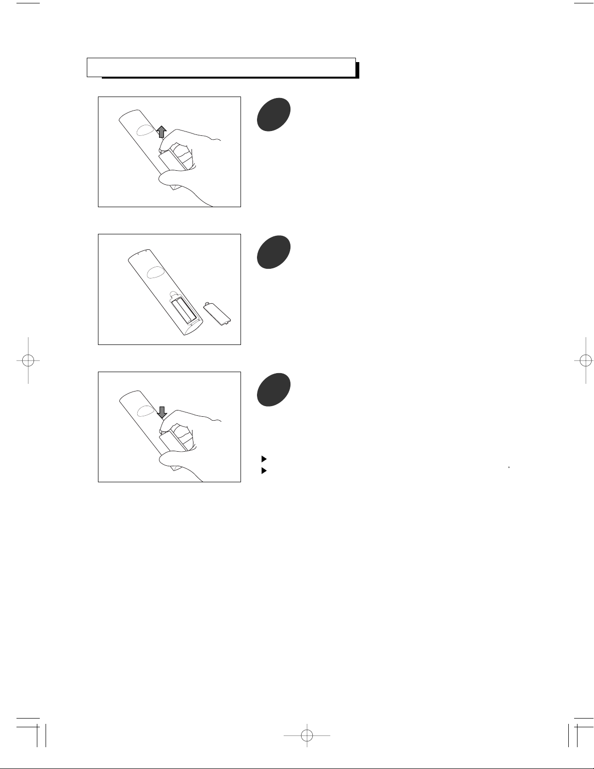
INST ALLING BATTERIES IN THE REMO TE CONTR OL
Pull the battery cover upward in the directions shown by
the arrow and remove it.
2
+
+
Insert two batteries (AAA size).
Make sure to match the “+” and “-” ends of the batteries
with the diagram inside the compartment.
3
Replace the battery cover.
The remote control can be used up to about 23 feet from the TV.
Remove the batteries and store them in a cool, dry place if you won t be
using the remote control for a long time.
Page 16
VIEWING THE MENU
POWER ON
PC AUTO
ENTERENTER
VOLVOL VOLVOL
123
456
7 809
SLEEP PRE.CH DISPLAY
MENU MUTE
STANDBY
P
.
M
O
D
E
P
.
S
I
Z
E
M
T
S
S
U
R
R
.
+
C
H
+
C
H
-
After turning the power on, press MENU
button.
The main menu appears on the screen. Its
top side has 7 icons: tv, settings, picture,
window, audio, time and options.
The on-screen menus disappear from the screen
after several seconds. This time interval can be
adjusted in the [options]-[osd timeout] menu. See
page 17 for details.
1
16
CH VOL.
MENU SOURCE
STANDBY/ON
POWER ON
PC AUTO
ENTER
VOL VOL
CHILD
LOCK
WINDOW
SEL.
PIP SWAP SRC
ADD/
ERASE CAPTION STILL
123
456
7809
SLEEP PRE.CH AUTOSET
MENU MUTE
SOURCE
STANDBY
C
H
+
C
H
-
P
.
M
O
D
E
P
.
S
I
Z
E
M
T
S
S
U
R
R
.
+
REMOTE CONTROL RM-501
CH VOL.
MENU SOURCE
STANDBY/ON
POWER ON
PC AUTO
ENTER
VOL VOL
CHILD
LOCK
WINDOW
SEL.
PIP SWAP SRC
ADD/
ERASE CAPTION STILL
123
456
7809
SLEEP PRE.CH AUTOSET
MENU MUTE
SOURCE
STANDBY
C
H
+
C
H
-
P
.
M
O
D
E
P
.
S
I
Z
E
M
T
S
S
U
R
R
.
+
REMOTE CONTROL RM-501
Operations
TURNING THE POWER ON/OFF
POWER ONPOWER ON
PC AUTOPC AUTO
ENTERENTER
VOLVOL VOLVOL
CHILDCHILD
LOCKLOCK
ADD/ADD/
ERASEERASE CAPTIONCAPTION STILLSTILL
1 2 3
4 5 6
7 809
SLEEPSLEEP PRE.CHPRE.CH AUTOSETAUTOSET
MENUMENU MUTEMUTE
SOURCESOURCE
STSTANDBYANDBY
C
H
+
C
H
-
P
.
M
O
D
E
P
.
S
I
Z
E
M
T
S
S
U
R
R
.
+
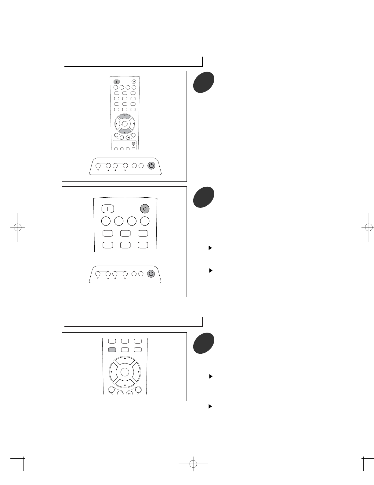
1
To turn the power on, press the POWER
ON button on the remote control.
You can also use the STANDBY/ON button
on top of the TV.
POWER ON
PC AUTOPC AUTO
1 2 3
4 5 6
SLEEPSLEEP PRE.CHPRE.CH AUTOSETAUTOSET
STANDBY
2
To turn the power off, press the STANDBY
button on the remote control.
You can also use the STANDBY/ON button
on top of the TV.
In STANDBY mode, the standby indicator
on the front panel lights up red.
When the power operation is in STANDBY mode,
the apparatus is still connected on some AC line
voltages.
Please be sure to unplug the cord when you leave
home for, say, a vacation.
If the electricity fails or the AC input cord is
unplugged while the power is on and plugged it
again, your TV enters directly into STANDBY mode.
Depending on input source and some operation
status, some menus cannot be selected and the
conditions of menu may differ.
Page 17
17
POWER ON
PC AUTO
ENTERENTER
VOLVOL VOLVOL
123
456
7809
SLEEP PRE.CH DISPLAY
MENU MUTE
STANDBY
P
.
M
O
D
E
P
.
S
I
Z
E
M
T
S
S
U
R
R
.
+
C
H
+
C
H
-
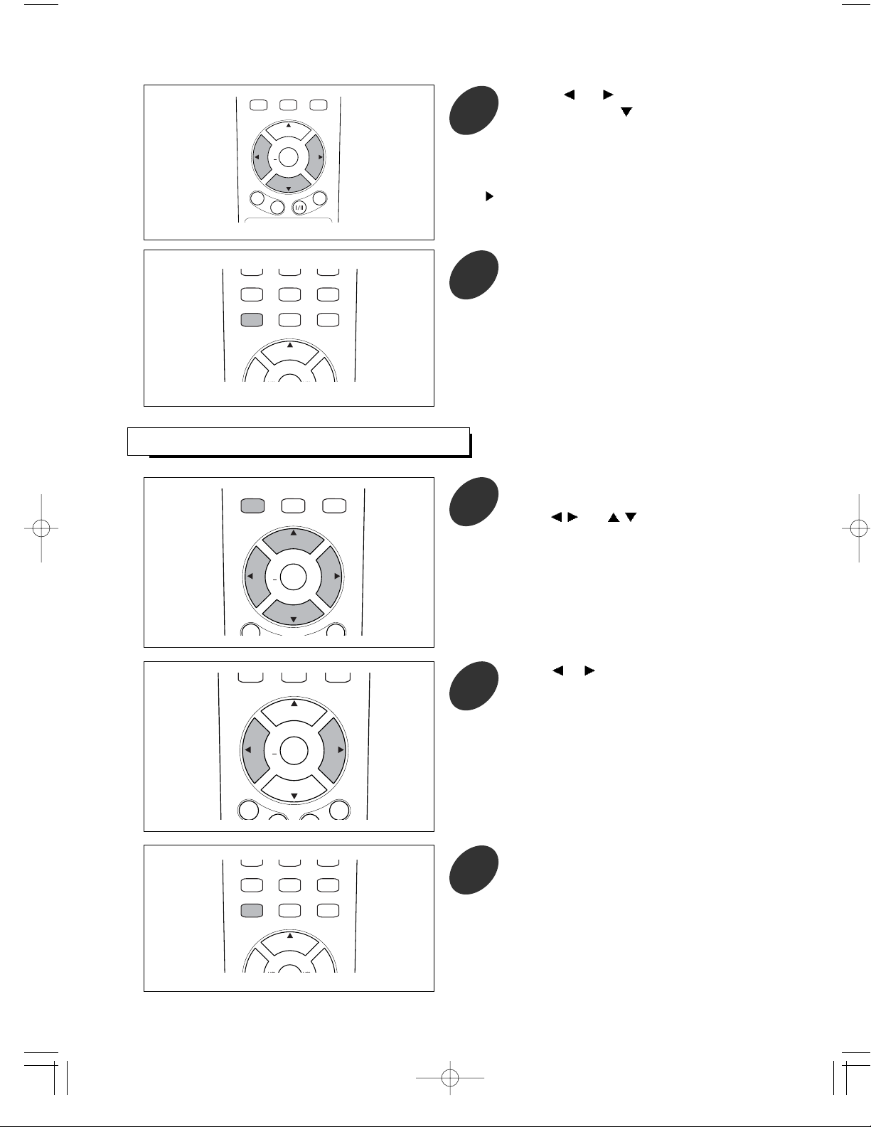
Use the or
button to select one of the
icons. Then press
button to access the
icon’s sub-menu.
You can also use the MENU, CHANNEL and VOLUME
buttons on the top panel of the TV to make
selections.
2
POWER ON
PC AUTO
123
4 5 6
7 8
0
9
SLEEP PRE.CH DISPLAY
MENUMENU MUTEMUTE
STANDBY
C
H
+
Press the MENU button repeatedly to exit.
3
SETTING THE OSD TIMEOUT
Press the MENU button to display the menu
and select [options] - [osd timeout] menu
using
/ and / buttons.
1
POWER ON
PC AUTO
ENTERENTER
VOLVOL VOLVOL
123
456
7809
SLEEP PRE.CH DISPLAY
MENUMENU MUTEMUTE
STANDBY
P
.
M
O
D
E
P
.
S
I
Z
E
M
T
S
S
U
R
R
.
+
C
H
+
C
H
-
Press or button to select appropriate
osd timeout interval: 5, 15, 60 sec.
2
POWER ON
PC AUTO
ENTER
VOL VOL
123
456
7809
SLEEP PRE.CH DISPLAY
MENU MUTE
STANDBY
P
.
M
O
D
E
P
.
S
I
Z
E
M
T
S
S
U
R
R
.
+
C
H
+
C
H
-
POWER ON
PC AUTO
123
4 5 6
7 8
0
9
SLEEP PRE.CH DISPLAY
MENUMENU MUTEMUTE
STANDBY
C
H
+
Press the MENU button repeatedly to exit.
3
Page 18
POWER ON
PC AUTO
123
4 5 6
7 8
0
9
SLEEP PRE.CH DISPLAY
MENUMENU MUTEMUTE
STANDBY
C
H
+
Press the MENU button repeatedly to exit.
4
POWER ON
PC AUTO
ENTERENTER
VOLVOL VOLVOL
123
456
7809
SLEEP PRE.CH DISPLAY
MENU MUTE
STANDBY
P
.
M
O
D
E
P
.
S
I
Z
E
M
T
S
S
U
R
R
.
+
C
H
+
C
H
-
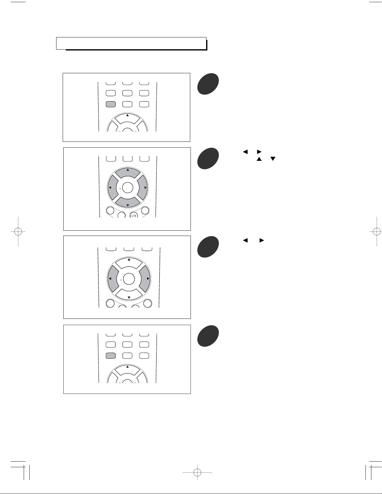
Press or button to select [options].
Then press
or button to select
[language].
2
POWER ON
PC AUTO
ENTERENTER
VOLVOL VOLVOL
123
456
7809
SLEEP PRE.CH DISPLAY
MENU MUTE
STANDBY
P
.
M
O
D
E
P
.
S
I
Z
E
M
T
S
S
U
R
R
.
+
C
H
+
C
H
-
Press or button to select appropriate
language : English, Spanish, French.
3
18
POWER ON
PC AUTO
123
4 5 6
7 8
0
9
SLEEP PRE.CH DISPLAY
MENUMENU MUTEMUTE
STANDBY
C
H
+
Press the MENU button to display the menu.
1
SELECTING A MENU LANGUAGE
For explanation purposes, this instuctions explains the menu language displayed on the screen in English.
Page 19
SELECTING INPUT SOURCE
19
You must select the appropriate mode in order to view each source on the TV.
Sources can be selected with automatic or manual method.
Auto-searching can be used with this method. You can set this method in on-screen menus.
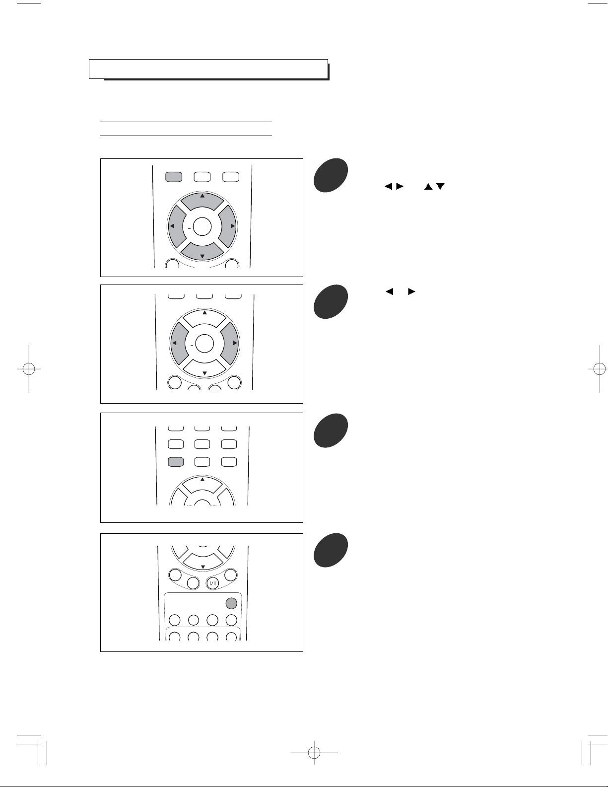
Press the MENU button to display the menu
and select [options] - [source select] menu
using
/ and / buttons.
1
Press the SOURCE button to select a
source you want.
Each time this button is pressed, the TV searches
all sources and automatically detects one of
connected and turned-on equipments.
4
POWER ON
PC AUTO
ENTER
VOL VOL
CHILDCHILD
LOCKLOCK
WINDOWWINDOW
SEL.SEL.
PIPPIP SWSWAPAP SRCSRC
ADD/ADD/
ERASEERASE CAPTIONCAPTION STILLSTILL
123
456
7809
SLEEP PRE.CH AUTOSET
MENU MUTE
SOURCESOURCE
STANDBY
C
H
+
C
H
-
P
.
M
O
D
E
P
.
S
I
Z
E
M
T
S
S
U
R
R
.
+
Auto Selection
Press or button to select the “auto”.
2
POWER ON
PC AUTO
ENTERENTER
VOLVOL VOLVOL
123
456
7809
SLEEP PRE.CH DISPLAY
MENU MUTE
STANDBY
P
.
M
O
D
E
P
.
S
I
Z
E
M
T
S
S
U
R
R
.
+
C
H
+
C
H
-
POWER ON
PC AUTO
123
4 5 6
7 8
0
9
SLEEP PRE.CH DISPLAY
MENUMENU MUTEMUTE
STANDBY
C
H
+
Press the MENU button repeatedly to exit.
3
POWER ON
PC AUTO
ENTERENTER
VOLVOL VOLVOL
123
456
7809
SLEEP PRE.CH DISPLAY
MENUMENU MUTEMUTE
STANDBY
P
.
M
O
D
E
P
.
S
I
Z
E
M
T
S
S
U
R
R
.
+
C
H
+
C
H
-
Page 20
20
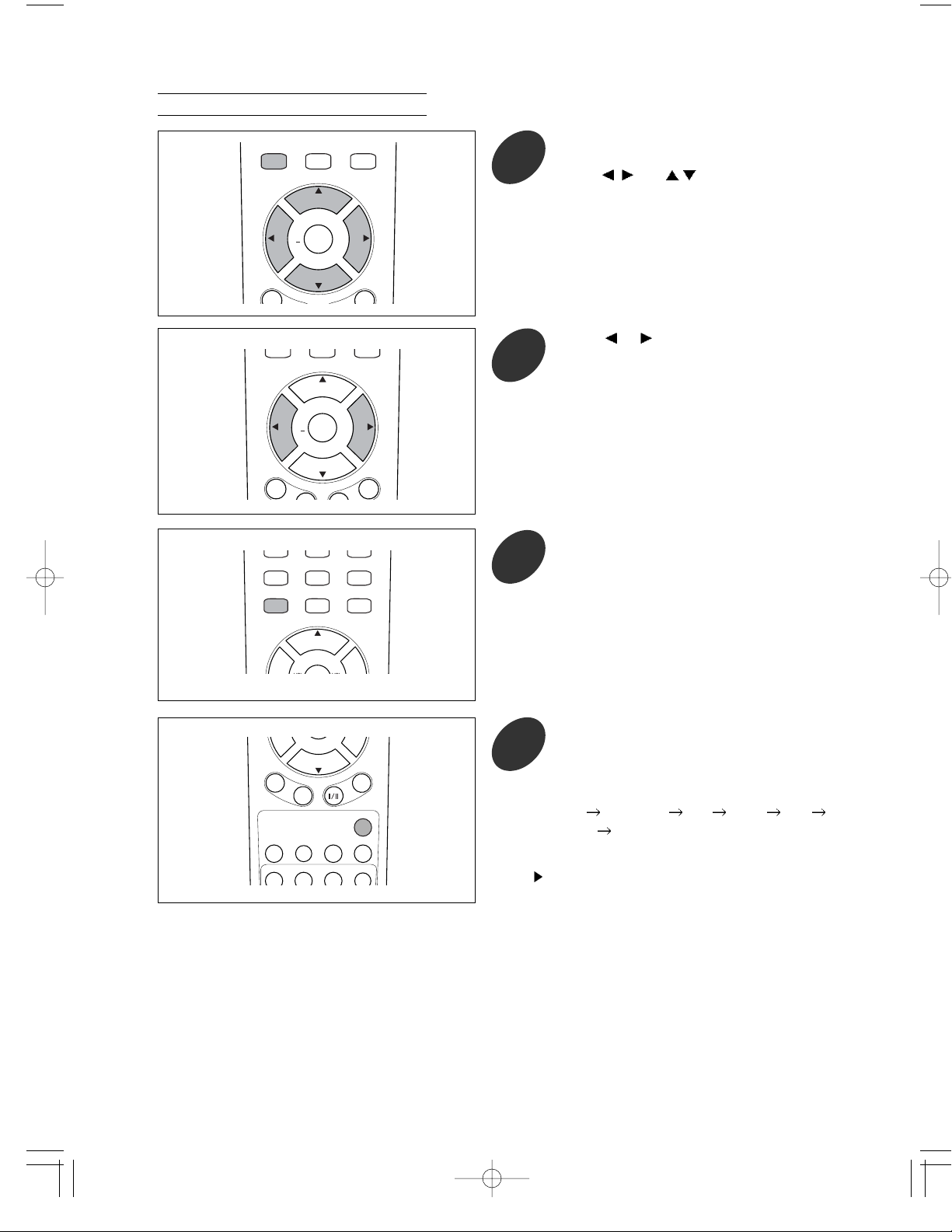
Press the MENU button to display the menu
and select [options] - [source select] menu
using
/
and
/ buttons.
1
Press the SOURCE button to select a
source you want.
4
POWER ON
PC AUTO
ENTER
VOL VOL
CHILDCHILD
LOCKLOCK
WINDOWWINDOW
SEL.SEL.
PIPPIP SWSWAPAP SRCSRC
ADD/ADD/
ERASEERASE CAPTIONCAPTION STILLSTILL
123
456
7809
SLEEP PRE.CH AUTOSET
MENU MUTE
SOURCESOURCE
STANDBY
C
H
+
C
H
-
P
.
M
O
D
E
P
.
S
I
Z
E
M
T
S
S
U
R
R
.
+
Manual Selection
Press
or button to select the “manual”.
2
POWER ON
PC AUTO
123
4 5 6
7 8
0
9
SLEEP PRE.CH DISPLAY
MENUMENU MUTEMUTE
STANDBY
C
H
+
Press the MENU button repeatedly to exit.
3
POWER ON
PC AUTO
ENTERENTER
VOLVOL VOLVOL
123
456
7809
SLEEP PRE.CH DISPLAY
MENUMENU MUTEMUTE
STANDBY
P
.
M
O
D
E
P
.
S
I
Z
E
M
T
S
S
U
R
R
.
+
C
H
+
C
H
-
POWER ON
PC AUTO
ENTERENTER
VOLVOL VOLVOL
123
456
7809
SLEEP PRE.CH DISPLAY
MENU MUTE
STANDBY
P
.
M
O
D
E
P
.
S
I
Z
E
M
T
S
S
U
R
R
.
+
C
H
+
C
H
-
Each time this button is pressed, the source
will be changed as fjollows:
TV
S-VIDEO AV DVD PC
DTV
TV
In case of selecting PC, refer to “USING YOUR TV AS
A COMPUTER(PC) DISPLAY” on page 60.
Page 21

21
Selecting A Broadcast Source
When you select the TV mode as input source, you should select the broadcast source.
Press the MENU button to display the menu
and select [tv] - [source] menu using
/
and
/ buttons.
1
Press or button to select the
“antenna”(air) or “cable”.
2
POWER ON
PC AUTO
ENTERENTER
VOLVOL VOLVOL
123
456
7809
SLEEP PRE.CH DISPLAY
MENU MUTE
STANDBY
P
.
M
O
D
E
P
.
S
I
Z
E
M
T
S
S
U
R
R
.
+
C
H
+
C
H
-
POWER ON
PC AUTO
123
4 5 6
7 8
0
9
SLEEP PRE.CH DISPLAY
MENUMENU MUTEMUTE
STANDBY
C
H
+
Press the MENU button repeatedly to exit.
3
POWER ON
PC AUTO
ENTERENTER
VOLVOL VOLVOL
123
456
7809
SLEEP PRE.CH DISPLAY
MENUMENU MUTEMUTE
STANDBY
P
.
M
O
D
E
P
.
S
I
Z
E
M
T
S
S
U
R
R
.
+
C
H
+
C
H
-
antenna : when viewing antenna(air) channels
cable : when viewing cable channels
Page 22

ADJUSTING THE VOLUME
22
Press the VOL + or VOL - button to increase or
decrease the volume.
POWER ON
PC AUTO
ENTERENTER
VOLVOL VOLVOL
123
456
7809
SLEEP PRE.CH DISPLAY
MENU MUTE
STANDBY
P
.
M
O
D
E
P
.
S
I
Z
E
M
T
S
S
U
R
R
.
+
C
H
+
C
H
-
Auto Volume
Each broadcasting station has its own signal conditions, and it is inconvenient to adjust the volume every time the
channel is changed. “auto volume” automatically adjusts the volume of the desired channel by lowering the sound
output when the modulation signal is high or by rasing the sound output when the modulation signal is low.
Press the MENU button to display the menu
and select [audio] - [auto volume] menu
using / and /
buttons.
1
Pressing or button to select “on”.
To cancel auto volume function, select “off”.
2
POWER ON
PC AUTO
ENTER
VOL VOL
123
456
7809
SLEEP PRE.CH DISPLAY
MENU MUTE
STANDBY
P
.
M
O
D
E
P
.
S
I
Z
E
M
T
S
S
U
R
R
.
+
C
H
+
C
H
-
Press MENU button repeatedly to exit.
3
POWER ON
PC AUTO
ENTER
VOL VOL
123
456
7 8
0
9
SLEEP PRE.CH DISPLAY
MENUMENU MUTEMUTE
STANDBY
+
C
H
+
POWER ON
PC AUTO
ENTERENTER
VOLVOL VOLVOL
123
456
7809
SLEEP PRE.CH DISPLAY
MENUMENU MUTEMUTE
STANDBY
P
.
M
O
D
E
P
.
S
I
Z
E
M
T
S
S
U
R
R
.
+
C
H
+
C
H
-
Page 23

23
LISTENING WITH HEADPHONES
Using Mute
POWER ON
PC AUTO
ENTERENTER
VOLVOL VOLVOL
123
456
7 8
0
9
SLEEP PRE.CH AUTOSET
MENUMENU MUTEMUTE
STANDBY
C
H
+
+
Press the MUTE button
Then the sound is cut off and
is displayed at lower-right corner of the
screen.
1
POWER ON
PC AUTO
ENTERENTER
VOLVOL VOLVOL
123
456
7 8
0
9
SLEEP PRE.CH AUTOSET
MENUMENU MUTEMUTE
STANDBY
C
H
+
C
H
-
P
.
M
O
D
E
P
.
S
I
Z
E
M
T
S
S
U
R
R
.
+
To turn mute off, press the MUTE button
again or VOL +/-, SURR. button,etc.
2
-
Plug the headphones into the headphone jack on
rear of the TV.
No sound is heard from the TV speakers.
Page 24

MEMORIZING THE CHANNELS
24
Stroing Channels In Memory (Automatic Method)
Once you have memorized the available channels, you can use the CH +/- buttons to scan the memorized channels.
Channels can be tuned with automatic or manual method.
Before memorizing channels, first select the broadcast source.(Refer to “Selecting A Broadcast Source” on page 21 )
All of the receivable channels can be stored by this method.
You would better use this method during installation of your TV.
Press the MENU button to display the menu
and select [tv] - [autoset] menu using
/
and / buttons.
1
POWER ON
PC AUTO
ENTERENTER
VOLVOL VOLVOL
123
456
7809
SLEEP PRE.CH DISPLAY
MENU MUTE
STANDBY
P
.
M
O
D
E
P
.
S
I
Z
E
M
T
S
S
U
R
R
.
+
C
H
+
C
H
-
Press ENTER or button to begin autoset.
2
To stop autoset, press the MENU button.
POWER ON
PC AUTO
ENTERENTER
VOLVOL VOLVOL
123
456
7809
SLEEP PRE.CH DISPLAY
MENUMENU MUTEMUTE
STANDBY
P
.
M
O
D
E
P
.
S
I
Z
E
M
T
S
S
U
R
R
.
+
C
H
+
C
H
-
After all the receivable channels are stored,
the [tv] - [autoset] menu reappears.
Press the MENU button repeatedly to exit.
3
POWER ON
PC AUTO
123
4 5 6
7 8
0
9
SLEEP PRE.CH DISPLAY
MENUMENU MUTEMUTE
STANDBY
C
H
+
POWER ON
PC AUTOPC AUTO
1 2 3
4 5 6
SLEEPSLEEP PRE.CHPRE.CH AUTOSETAUTOSET
STANDBY
Press the AUTOSET button on the remote control.
Quick way
To stop autoset, press the MENU button.
Page 25

Press or button to select “add” or
“erase”.
After selecting one of them, the
corresponding channel is added or erased.
4
POWER ON
PC AUTO
ENTERENTER
VOLVOL VOLVOL
123
456
7809
SLEEP PRE.CH DISPLAY
MENU MUTE
STANDBY
P
.
M
O
D
E
P
.
S
I
Z
E
M
T
S
S
U
R
R
.
+
C
H
+
C
H
-
25
Press the MENU button to display the menu
and select [tv]-[channel] menu using
/
and / buttons.
1
POWER ON
PC AUTO
ENTER
VOL VOL
123
456
7809
SLEEP PRE.CH DISPLAY
MENU MUTE
STANDBY
P
.
M
O
D
E
S
U
R
R
.
+
C
H
+
C
H
-
Adding And Erasing Channels (Manual Method)
Press
button to select [edit channels]
menu.
3
POWER ON
PC AUTO
ENTER
VOL VOL
123
456
7809
SLEEP PRE.CH AUTOSET
MENU MUTE
STANDBY
C
H
+
C
H
-
P
.
M
O
D
E
P
.
S
I
Z
E
M
T
S
S
U
R
R
.
+
Press or
button to select a channel to
be added or erased.
2
POWER ON
PC AUTO
ENTER
VOL VOL
123
456
7809
SLEEP PRE.CH DISPLAY
MENU MUTE
STANDBY
P
.
M
O
D
E
P
.
S
I
Z
E
M
T
S
S
U
R
R
.
+
C
H
+
C
H
-
If you want to add or erase another
channel(s), repeat the upper steps 1 to 4.
If not, press MENU button repeatedly to exit.
5
POWER ON
PC AUTO
123
4 5 6
7 8
0
9
SLEEP PRE.CH DISPLAY
MENUMENU MUTEMUTE
STANDBY
C
H
+
You can view any channel (including an erased
channel) by using the number buttons on the remote
control.
Page 26

26
POWER ON
PC AUTO
ENTER
VOL VOL
CHILDCHILD
LOCKLOCK
WINDOWWINDOW
SEL.SEL.
PIPPIP SWSWAPAP SRCSRC
ADD/ADD/
ERASEERASE CAPTIONCAPTION STILLSTILL
123
456
7809
SLEEP PRE.CH AUTOSET
MENU MUTE
SOURCESOURCE
STANDBY
C
H
+
C
H
-
P
.
M
O
D
E
P
.
S
I
Z
E
M
T
S
S
U
R
R
.
+
Press ADD/ERASE button.
Quick way
2
Select the channel you want to add or erase
by pressing CH +/- buttons.
1
POWER ON
PC AUTO
ENTERENTER
VOLVOL VOLVOL
123
456
7809
SLEEP PRE.CH DISPLAY
MENU MUTE
STANDBY
P
.
M
O
D
E
P
.
S
I
Z
E
M
T
S
S
U
R
R
.
+
C
H
+
C
H
-
If you want to add or erase another
channel(s), repeat the above steps 1 to 3.
If not, press MENU button to exit.
4
POWER ON
PC AUTO
123
4 5 6
7 8
0
9
SLEEP PRE.CH DISPLAY
MENUMENU MUTEMUTE
STANDBY
C
H
+
POWER ON
PC AUTO
ENTER
VOL VOL
123
456
7809
SLEEP PRE.CH DISPLAY
MENU MUTE
STANDBY
P
.
M
O
D
E
P
.
S
I
Z
T
S
S
U
R
R
.
+
C
H
+
C
H
-
Press or button to select the "add" or
"erase".
To adjust other items as desired, repeat the
above steps 1 to 3.
3
You can view any channel (including an removed
channel) by using the number buttons on the remote
control.
Page 27

CHANGING CHANNELS
27
Using the Channel +/- Buttons
Press the CH + or CH - button to change channels.
POWER ON
PC AUTO
ENTERENTER
VOLVOL VOLVOL
123
456
7809
SLEEP PRE.CH DISPLAY
MENU MUTE
STANDBY
P
.
M
O
D
E
P
.
S
I
Z
E
M
T
S
S
U
R
R
.
+
C
H
+
C
H
-
Whenever you press these buttons, the TV changes
channels in sequence. You will see all the channels
that have been memorized. You will not see
channels that were either erased or not memorized.
Press the MENU button to display the
menu and select [tv] - [channel] menu
using / and / buttons.
1
POWER ON
PC AUTO
ENTERENTER
VOLVOL VOLVOL
123
456
7809
SLEEP PRE.CH DISPLAY
MENUMENU MUTEMUTE
STANDBY
P
.
M
O
D
E
P
.
S
I
Z
E
M
T
S
S
U
R
R
.
+
C
H
+
C
H
-
Using On-Screen Menu
Press or to change channels.
2
POWER ON
PC AUTO
ENTERENTER
VOLVOL VOLVOL
123
456
7809
SLEEP PRE.CH DISPLAY
MENU MUTE
STANDBY
P
.
M
O
D
E
P
.
S
I
Z
E
M
T
S
S
U
R
R
.
+
C
H
+
C
H
-
Press MENU button repeatedly to exit.
3
POWER ON
PC AUTO
ENTER
VOL VOL
123
4 5 6
7 8
0
9
SLEEP PRE.CH DISPLAY
MENU MUTE
STANDBY
C
H
+
Page 28

28
Directly Accessing Channels
Selecting the Previous Channel
Press the PRE.CH button.
The TV will switch to the last channel viewed.
POWER ONPOWER ON
PC AUTOPC AUTO
1 2 3
4 5 6
SLEEPSLEEP PRE.CHPRE.CH AUTOSETAUTOSET
STANDBY
To quickly switch between two channels that are far
apart, tune to one channel, then use the number
button to select the second channel. Then, use the
PRE.CH button to quickly alternate between them.
Press the number buttons to go directly to a
channel.
For example, to select channel 71, press “7”, then
“1”. The TV will change channels after you press
the second number.
You can also change to single-digit channels as
follows: for channel 7,
just press “7”
or “0”, then “7”
or “0”, “0” then “7”
POWER ON
PC AUTOPC AUTO
1 2 3
4 5 6
7 8
0
9
SLEEPSLEEP PRE.CHPRE.CH AUTOSETAUTOSET
MENUMENU MUTEMUTE
STANDBY
Use the number buttons to quickly tune to any channel, even that was erased or not memorized.
Page 29

CUSTOMIZING THE PICTURE
29
You can use the on-screen menus to adjust the brightness, contrast, filter, sharpness, color and tint according to personal
preference (each items(sub-menus) can be varied according to the input source.).
Alternatively, you can use one of the “automatic” settings. See next page.
Press the MENU button to display the menu
and select [picture] menu using
or
button.
1
POWER ON
PC AUTO
ENTER
VOLVOL VOLVOL
123
456
7 8
0
9
SLEEP PRE.CH DISPLAY
MENUMENU MUTEMUTE
STANDBY
P
.
M
O
D
E
S
U
R
R
.
+
C
H
+
C
H
-
Press or button to select a particular
item.
2
POWER ON
PC AUTO
ENTER
VOLVOL VOLVOL
123
456
7809
SLEEP PRE.CH DISPLAY
MENUMENU MUTEMUTE
STANDBY
P
.
M
O
D
E
P
.
S
I
Z
E
M
T
S
S
U
R
R
.
+
C
H
+
C
H
-
Press
or button to change the value of
a particular item.
For example, if you select [contrast],
pressing
increases it.
To adjust other items as desired, repeat the
above steps 1 to 3.
3
POWER ON
PC AUTO
ENTER
VOLVOL VOLVOL
123
456
7809
SLEEP PRE.CH DISPLAY
MENUMENU MUTEMUTE
STANDBY
P
.
M
O
D
E
P
.
S
I
Z
E
M
T
S
S
U
R
R
.
+
C
H
+
C
H
-
POWER ON
PC AUTO
123
4 5 6
7 8
0
9
SLEEP PRE.CH DISPLAY
MENUMENU MUTEMUTE
STANDBY
C
H
+
Press the MENU button repeatedly to exit.
4
Page 30

USING AUT OMATIC PICTURE SETTINGS
30
Your TV has four automatic picture settings ("normal”, "movie", "sports" and "bright" ) that are preset at the factory. You
can activate each picture setting by pressing the P.MODE button.
POWER ON
PC AUTO
ENTER
VOLVOL VOLVOL
123
456
78
0
+
100
9
SLEEP PRE.CH DISPLAY
MENU
SOURCESOURCE
STANDBY
P
.
M
O
D
E
P
.
S
I
Z
E
M
T
S
S
U
R
R
.
+
C
H
+
C
H
-
Press the P.MODE button to select one of the
picture settings.
Choose “normal” for normal screen.
Choose “movie” to enjoy a movie as in a theater.
Choose “sports” to enjoy sports as in a stadium.
Choose “bright” for brighter screen.
CHANGING THE SCREEN SIZE
CHANGING THE SCREEN POSITION
You can change the screen size according to the program sources to be played back.
Press the P.SIZE button to select one of the screen
size settings.
Choose “normal” to set the picture to 4:3 normal
mode. This is a standard TV screen size.
Choose “wide” to set to 16:9 wide mode.
Choose “zoom” to magnify the size of the picture
on the screen.
Choose “video game zoom” to magnify the size of
the picture when enjoying a video game.
Choose “fill all” to view 4:3 programs in full
screen.
Choose “anamorphic” to view 2.35:1 anamorphic
DVDs in full screen
45
8
POWER ON
PC AUTO
ENTERENTER
VOLVOL VOLVOL
123
6
7
0
+
100
9
SLEEP PRE.CH DISPLAY
MENU
SOURCESOURCE
STANDBY
P
.
M
O
D
E
P
.
S
I
Z
E
M
T
S
S
U
R
R
.
+
C
H
+
C
H
-
Press the MENU button to display the menu
and select [window] - [h position] or [v
position] using
/ and / buttons.
1
POWER ON
PC AUTO
ENTERENTER
VOLVOL VOLVOL
123
456
7809
SLEEP PRE.CH DISPLAY
MENUMENU MUTEMUTE
STANDBY
P
.
M
O
D
E
P
.
S
I
Z
E
M
T
S
S
U
R
R
.
+
C
H
+
C
H
-
The screen position can be changed also in other sources (TV, AV, etc.)
Page 31

31
The on-screen displays disappear after several
seconds.
If this button is pressed when PC is selected for
signal source, TV will display the resolution
information.
VIEWING THE CURRENT ST ATUS
POWER ON
PC AUTO
ENTERENTER
VOLVOL VOLVOL
123
456
7809
SLEEP PRE.CH AUTOSET
MENU MUTE
STANDBY
P
.
M
O
D
E
P
.
S
I
Z
E
M
T
S
S
U
R
R
.
+
C
H
+
C
H
-
This function indentifies the current channel or the
status of certain audio-video conditions, etc.
Press the ENTER button on the remote control.
The TV will display the channel number, time
information, or audio-video conditions, etc.
Press or to adjust the position.
2
POWER ON
PC AUTO
ENTER
VOL VOL
123
456
7809
SLEEP PRE.CH DISPLAY
MENU MUTE
STANDBY
P
.
M
O
D
E
P
.
S
I
Z
E
M
T
S
S
U
R
R
.
+
C
H
+
C
H
-
Press MENU button repeatedly to exit.
3
POWER ON
PC AUTO
ENTER
VOL VOL
123
4 5 6
7 8
0
9
SLEEP PRE.CH DISPLAY
MENU MUTE
STANDBY
+
C
H
+
Page 32

CUSTOMIZING THE SOUND
32
The [treble], [bass] and [balance] can be adjusted to suit your personal preference.
These can be selected when the [surround mode] menu is set to “user”. Refer to next page.
Press the MENU button to display the menu
and select [audio] menu using
or
buttons.
1
POWER ON
PC AUTO
ENTER
VOLVOL VOLVOL
123
456
7 8
0
9
SLEEP PRE.CH DISPLAY
MENUMENU MUTEMUTE
STANDBY
P
.
M
O
D
E
S
U
R
R
.
+
C
H
+
C
H
-
Press or button to select a particular
item.
2
POWER ON
PC AUTO
ENTER
VOLVOL VOLVOL
123
456
7809
SLEEP PRE.CH DISPLAY
MENUMENU MUTEMUTE
STANDBY
P
.
M
O
D
E
P
.
S
I
Z
E
M
T
S
S
U
R
R
.
+
C
H
+
C
H
-
Press
or button to change the value of
a particular item.
For example, if you select [treble], pressing
button increases it.
To adjust other items as desired, repeat the
above steps 2 and 3.
3
POWER ON
PC AUTO
ENTER
VOLVOL VOLVOL
123
456
7809
SLEEP PRE.CH DISPLAY
MENUMENU MUTEMUTE
STANDBY
P
.
M
O
D
E
P
.
S
I
Z
E
M
T
S
S
U
R
R
.
+
C
H
+
C
H
-
POWER ON
PC AUTO
123
4 5 6
7 8
0
9
SLEEP PRE.CH DISPLAY
MENUMENU MUTEMUTE
STANDBY
C
H
+
Press the MENU button repeatedly to exit.
4
Page 33

SELECTING A SURROUND SOUND
33
Your TV has five automatic sound settings (“standard”, “music”, “movie”, “sports”, “news”, and “user”) that are preset
at the factory. You can activate any of them by making a selection from the on-screen menu).
POWER ON
PC AUTO
123
4 5 6
7 8
0
9
SLEEP PRE.CH DISPLAY
MENUMENU MUTEMUTE
STANDBY
C
H
+
Press the MENU button repeatedly to exit.
3
Press the MENU button to display the menu
and select [audio] - [surround mode] menu
using
/
and / button.
1
POWER ON
PC AUTO
ENTERENTER
VOLVOL VOLVOL
123
456
7809
SLEEP PRE.CH DISPLAY
MENUMENU MUTEMUTE
STANDBY
P
.
M
O
D
E
P
.
S
I
Z
E
M
T
S
S
U
R
R
.
+
C
H
+
C
H
-
Press or button to select an
appropriate surround mode.
2
POWER ON
PC AUTO
ENTERENTER
VOLVOL VOLVOL
123
456
7809
SLEEP PRE.CH DISPLAY
MENU MUTE
STANDBY
P
.
M
O
D
E
P
.
S
I
Z
E
M
T
S
S
U
R
R
.
+
C
H
+
C
H
-
Choose “standard” for the standard factory
settings.
Choose “music” when watching music video or
concert.
Choose “movie” when watching movies.
Choose “sports” when watching sport games.
Choose “news” when watching news that is
mostly dialogue.
Choose “user” when adjusting audio items as you
want.
Press the SURR. button.
Each time this button is pressed, the surround mode
changes as follows:
standard
music movie sports news
user standard
Quick way
POWER ON
PC AUTO
ENTERENTER
VOLVOL VOLVOL
CHILDCHILD
LOCKLOCK
ADD/ADD/
ERASEERASE CAPTIONCAPTION STILLSTILL
123
456
78
0
+
100
9
SLEEP PRE.CH DISPLAY
MENU
SOURCESOURCE
STANDBY
P
.
M
O
D
E
P
.
S
I
Z
E
M
T
S
S
U
R
R
.
+
C
H
+
C
H
-
Page 34

FINE TUNING CHANNELS
Use fine tuning to manually adjust a particular channel for optimal reception.
Generally, fine tuning is only necessary if reception is poor.
Press the MENU button to display the menu
and select [tv] - [fine tune] menu using
/
and / buttons.
1
POWER ON
PC AUTO
ENTERENTER
VOLVOL VOLVOL
123
456
7809
SLEEP PRE.CH DISPLAY
MENUMENU MUTEMUTE
STANDBY
P
.
M
O
D
E
P
.
S
I
Z
E
M
T
S
S
U
R
R
.
+
C
H
+
C
H
-
34
Press the MENU button to display the menu
and select [options] - [menu background]
menu using
/ and / buttons.
1
POWER ON
PC AUTO
ENTERENTER
VOLVOL VOLVOL
123
456
7809
SLEEP PRE.CH DISPLAY
MENUMENU MUTEMUTE
STANDBY
P
.
M
O
D
E
P
.
S
I
Z
E
M
T
S
S
U
R
R
.
+
C
H
+
C
H
-
Pressing or button changes the
caption background as follows:
opaque
translucent
2
POWER ON
PC AUTO
ENTER
VOL VOL
123
456
7809
SLEEP PRE.CH DISPLAY
MENU MUTE
STANDBY
P
.
M
O
D
E
P
.
S
I
Z
E
M
T
S
S
U
R
R
.
+
C
H
+
C
H
-
Press MENU button repeatedly to exit.
3
POWER ON
PC AUTO
123
456
7 8
0
9
SLEEP PRE.CH DISPLAY
MENUMENU MUTEMUTE
STANDBY
SELECTING THE BACK GROUND OF MENU
Special Features
Page 35

Press ENTER or button.
2
POWER ON
PC AUTO
ENTERENTER
VOLVOL VOLVOL
123
456
7809
SLEEP PRE.CH DISPLAY
MENU MUTE
STANDBY
P
.
M
O
D
E
P
.
S
I
Z
E
M
T
S
S
U
R
R
.
+
C
H
+
C
H
-
Press or button to adjust the fine
tuning.
3
POWER ON
PC AUTO
123
456
7 8
0
9
SLEEP PRE.CH DISPLAY
MENUMENU MUTEMUTE
STANDBY
Press the MENU button repeatedly to exit .
4
35
POWER ON
PC AUTO
ENTERENTER
VOLVOL VOLVOL
123
456
7809
SLEEP PRE.CH DISPLAY
MENU MUTE
STANDBY
P
.
M
O
D
E
P
.
S
I
Z
E
M
T
S
S
U
R
R
.
+
C
H
+
C
H
-
LABELING THE CHANNEL NAME
You can label the channel name as you want.
At a particular channel, press the MENU
button to display the menu and select [tv] [edit labels] using / and
/ buttons.
1
POWER ON
PC AUTO
ENTERENTER
VOLVOL VOLVOL
123
456
7809
SLEEP PRE.CH DISPLAY
MENUMENU MUTEMUTE
STANDBY
P
.
M
O
D
E
P
.
S
I
Z
E
M
T
S
S
U
R
R
.
+
C
H
+
C
H
-
Press ENTER or button to enter into sub
menu.
2
POWER ON
PC AUTO
ENTERENTER
VOLVOL VOLVOL
123
456
7809
SLEEP PRE.CH DISPLAY
MENU MUTE
STANDBY
P
.
M
O
D
E
P
.
S
I
Z
E
M
T
S
S
U
R
R
.
+
C
H
+
C
H
-
Page 36

FREEZING THE PICTURE
Press the MENU button to display the menu
and select [window] - [freeze window] menu
using
/ and / buttons.
1
POWER ON
PC AUTO
ENTERENTER
VOLVOL VOLVOL
123
456
7809
SLEEP PRE.CH DISPLAY
MENUMENU MUTEMUTE
STANDBY
P
.
M
O
D
E
P
.
S
I
Z
E
M
T
S
S
U
R
R
.
+
C
H
+
C
H
-
At a particular scene, press or button
to select the “on”.
2
POWER ON
PC AUTO
ENTERENTER
VOLVOL VOLVOL
123
456
7809
SLEEP PRE.CH DISPLAY
MENU MUTE
STANDBY
P
.
M
O
D
E
P
.
S
I
Z
E
M
T
S
S
U
R
R
.
+
C
H
+
C
H
-
Then the moving image is freezed.
(Sournd is still heard.)
To cancel this function, repeat the above steps 1
and 2 to select the "off".
36
POWER ON
PC AUTO
ENTERENTER
VOLVOL VOLVOL
123
456
7809
SLEEP PRE.CH DISPLAY
MENU MUTE
STANDBY
P
.
M
O
D
E
P
.
S
I
Z
E
M
T
S
S
U
R
R
.
+
C
H
+
C
H
-
Press to move the cursor.
Repeat above steps 3 and 4 to fill another
characters.
It can be filled up to 5 characters.
To clear the channel name, press the
SOURCE button.
4
Press or button to select characters :
A~Z, a~z, 0 ~ 9, !, “, #, $, %, &, ‘, (, ), *,
+, ,, -, ., /, :, ;, <, =, >, ?, @, [, \, ], ^, _,
`,space
3
POWER ON
PC AUTO
ENTERENTER
VOLVOL VOLVOL
123
456
7809
SLEEP PRE.CH DISPLAY
MENU MUTE
STANDBY
P
.
M
O
D
E
P
.
S
I
Z
E
M
T
S
S
U
R
R
.
+
C
H
+
C
H
-
POWER ON
PC AUTO
123
4 5 6
7 8
0
9
SLEEP PRE.CH DISPLAY
MENUMENU MUTEMUTE
STANDBY
C
H
+
Press the MENU button repeatedly to exit.
To label other channel names, repeat the
above the steps 1 to 4.
5
Page 37

37
POWER ON
PC AUTO
ENTER
VOL VOL
CHILDCHILD
LOCKLOCK
WINDOWWINDOW
SEL.SEL.
PIPPIP SWSWAPAP SRCSRC
ADD/ADD/
ERASEERASE CAPTIONCAPTION STILLSTILL
123
456
7809
SLEEP PRE.CH AUTOSET
MENU MUTE
SOURCESOURCE
STANDBY
C
H
+
C
H
-
P
.
M
O
D
E
P
.
S
I
Z
E
M
T
S
S
U
R
R
.
+
Press the STILL button at a particular scene.
Press again to cancel.
Quick way
POWER ON
PC AUTO
123
4 5 6
7 8
0
9
SLEEP PRE.CH DISPLAY
MENUMENU MUTEMUTE
STANDBY
C
H
+
Press the MENU button repeatedly to exit.
3
This function can zoom any picture on the screen and pan to 4 directions.
Press the MENU button to display the menu
and select [window] - [digital pan and zoom]
using
/ and / buttons.
1
POWER ON
PC AUTO
ENTERENTER
VOLVOL VOLVOL
123
456
7809
SLEEP PRE.CH DISPLAY
MENUMENU MUTEMUTE
STANDBY
P
.
M
O
D
E
P
.
S
I
Z
E
M
T
S
S
U
R
R
.
+
C
H
+
C
H
-
Press ENTER or button to enter into sub
menu.
2
POWER ON
PC AUTO
ENTERENTER
VOLVOL VOLVOL
123
456
7809
SLEEP PRE.CH DISPLAY
MENUMENU MUTEMUTE
STANDBY
P
.
M
O
D
E
P
.
S
I
Z
T
S
S
U
R
R
.
+
C
H
+
C
H
-
DIGIT AL PAN AND ZOOM
Zooming the Picture
Page 38

Press the MENU button to display the menu
and select [window] - [digital pan and zoom]
using
/ and / buttons.
1
POWER ON
PC AUTO
ENTERENTER
VOLVOL VOLVOL
123
456
7809
SLEEP PRE.CH DISPLAY
MENUMENU MUTEMUTE
STANDBY
P
.
M
O
D
E
P
.
S
I
Z
E
M
T
S
S
U
R
R
.
+
C
H
+
C
H
-
Press ENTER or button to enter into
zoom mode.
2
POWER ON
PC AUTO
ENTERENTER
VOLVOL VOLVOL
123
456
7809
SLEEP PRE.CH DISPLAY
MENU MUTE
STANDBY
P
.
M
O
D
E
P
.
S
I
Z
E
M
T
S
S
U
R
R
.
+
C
H
+
C
H
-
Press repeatedly or hold down or
button to zoom the scene as you want.
3
POWER ON
PC AUTO
ENTERENTER
VOLVOL VOLVOL
123
456
7809
SLEEP PRE.CH DISPLAY
MENU MUTE
STANDBY
P
.
M
O
D
E
P
.
S
I
Z
E
M
T
S
S
U
R
R
.
+
C
H
+
C
H
-
Panning the Picture
38
Each time or button is pressed, the
picture is magnified as follows:
1.0
1.06 1.19 1.38 1.69
2.06
2.50 3.0 3.63 4.38
5.13 6.00 6.94 8.00
9.13 10.31 11.56 12.94
14.44 15.94
To pan the picture, perform the step 5 in
"Panning the Picture" procedure on page 39.
3
POWER ON
PC AUTO
ENTERENTER
VOLVOL VOLVOL
123
456
7809
SLEEP PRE.CH DISPLAY
MENU MUTE
STANDBY
P
.
M
O
D
E
P
.
S
I
Z
E
M
T
S
S
U
R
R
.
+
C
H
+
C
H
-
POWER ON
PC AUTO
123
4 5 6
7 8
0
9
SLEEP PRE.CH DISPLAY
MENUMENU MUTEMUTE
STANDBY
C
H
+
Press the MENU button repeatedly to exit.
4
Page 39

39
Press ENTER button to change to pan mode
and then press
/
/ / button to move to
the part of scene.
4
POWER ON
PC AUTO
ENTERENTER
VOLVOL VOLVOL
123
456
7809
SLEEP PRE.CH AUTOSET
MENU MUTE
STANDBY
P
.
M
O
D
E
P
.
S
I
Z
E
M
T
S
S
U
R
R
.
+
C
H
+
C
H
-
Each time ENTER button is pressed, zoom mode
or pan mode is selected.
Press the MENU button repeatedly to exit.
You can make clearly sure of the zoom and pan functions when the picture is freezed in on-screen menu(refer to steps
1 to 3 in “FREEZING THE PICTURE” on page 36)
CHOOSING A MULTI-CHANNEL SOUND (MTS) SOUNDTRA CK
Press the MTS I/II button.
Depending on the particular program being broadcast, you can listen to stereo, mono, or a foreign-language
translation.
Mono sound selection
In stereo reception if the stereo signal is weak,
you can switch to mono by pressing the MTS I/II
button. In mono reception the depth of sound is
improved. To switch back to stereo, press the
MTS I/II button again.
Language selection for dual language broadcast
If a program is received in two languages (dual
language), you can switch to DUAL I, DUAL II or
DUAL I+II by pressing the MTS I/II button
repeatedly.
POWER ON
PC AUTO
ENTER
VOL VOL
CHILD
LOCK
ADD/
ERASE CAPTION STILL
123
456
78
0
+
100
9
SLEEP PRE.CH DISPLAY
MENU
SOURCE
STANDBY
P
.
M
O
D
E
P
.
S
I
Z
E
M
T
S
S
U
R
R
.
+
C
H
+
C
H
-
Page 40

SETTING THE CLOCK
40
Setting the clock is neccessary in order to use the timer features of the TV.
Also, you can check the time while watching the TV. (Just press ENTER button.)
Press the MENU button to display the menu
and select [time] - [clock] menu using
/
and /
buttons.
1
POWER ON
PC AUTO
ENTERENTER
VOLVOL VOLVOL
123
456
7809
SLEEP PRE.CH DISPLAY
MENUMENU MUTEMUTE
STANDBY
P
.
M
O
D
E
P
.
S
I
Z
E
M
T
S
S
U
R
R
.
+
C
H
+
C
H
-
Press button.
Then press or button repeatedly or
holding down either of these buttons until the
correct hour appears.
2
POWER ON
PC AUTO
ENTERENTER
VOLVOL VOLVOL
123
456
7809
SLEEP PRE.CH DISPLAY
MENU MUTE
STANDBY
P
.
M
O
D
E
P
.
S
I
Z
E
M
T
S
S
U
R
R
.
+
C
H
+
C
H
-
After the hour is set, press
button.
Then press
or button repeatedly or
hold down either of these buttons until the
correct minutes appear.
3
POWER ON
PC AUTO
ENTERENTER
VOLVOL VOLVOL
123
456
7809
SLEEP PRE.CH DISPLAY
MENU MUTE
STANDBY
P
.
M
O
D
E
P
.
S
I
Z
E
M
T
S
S
U
R
R
.
+
C
H
+
C
H
-
After the minutes are set,
Press MENU button repeatedly to exit.
4
POWER ON
PC AUTO
123
456
7 8
0
9
SLEEP PRE.CH DISPLAY
MENU MUTE
STANDBY
C
H
+
Page 41

41
SETTING THE ON/OFF TIMER
Press the MENU button to display the menu
and select [time] - [on time] menu using /
and / buttons.
1
POWER ON
PC AUTO
ENTERENTER
VOLVOL VOLVOL
123
456
7809
SLEEP PRE.CH DISPLAY
MENUMENU MUTEMUTE
STANDBY
P
.
M
O
D
E
P
.
S
I
Z
E
M
T
S
S
U
R
R
.
+
C
H
+
C
H
-
2
Press button.
Then press
or button repeatedly or
hold down either of these buttons until the
correct hour appears.(i.e., the hour when the
TV will turn on.)
3
POWER ON
PC AUTO
ENTERENTER
VOLVOL VOLVOL
123
456
7809
SLEEP PRE.CH DISPLAY
MENU MUTE
STANDBY
P
.
M
O
D
E
P
.
S
I
Z
E
M
T
S
S
U
R
R
.
+
C
H
+
C
H
-
After the hour is set, press
button.
Then press
or button repeatedly or
hold down either of these buttons until the
correct minutes appear.
4
POWER ON
PC AUTO
ENTERENTER
VOLVOL VOLVOL
123
456
7809
SLEEP PRE.CH DISPLAY
MENU MUTE
STANDBY
P
.
M
O
D
E
P
.
S
I
Z
E
M
T
S
S
U
R
R
.
+
C
H
+
C
H
-
Setting the On Timer
Make sure the clock has been set correctly before setting the timer.
After the minutes are set, press button.
Then press or button to select on or
off.
When off is selected, the on timer is
deactivated.
POWER ON
PC AUTO
ENTERENTER
VOLVOL VOLVOL
123
456
7809
SLEEP PRE.CH DISPLAY
MENU MUTE
STANDBY
P
.
M
O
D
E
P
.
S
I
Z
E
M
T
S
S
U
R
R
.
+
C
H
+
C
H
-
Page 42

42
POWER ON
PC AUTO
ENTERENTER
VOLVOL VOLVOL
123
456
7809
SLEEP PRE.CH DISPLAY
MENUMENU MUTEMUTE
STANDBY
P
.
M
O
D
E
P
.
S
I
Z
E
M
T
S
S
U
R
R
.
+
C
H
+
C
H
-
Press ENTER or button.
Then press
or
to select [channel]
menu.
5
Press or button repeatedly or hold
down either of these buttons until
appropriate channel is selected.
6
POWER ON
PC AUTO
ENTER
VOLVOL VOLVOL
123
456
7809
SLEEP PRE.CH DISPLAY
MENUMENU MUTEMUTE
STANDBY
P
.
M
O
D
E
P
.
S
I
Z
E
M
T
S
S
U
R
R
.
+
C
H
+
C
H
-
Press or button to select [volume]
menu.
7
POWER ON
PC AUTO
ENTER
VOL VOL
123
456
7809
SLEEP PRE.CH DISPLAY
MENU MUTE
STANDBY
P
.
M
O
D
E
P
.
S
I
Z
E
M
T
S
S
U
R
R
.
+
C
H
+
C
H
-
Press
or button repeatedly or hold
down either of these buttons until the volume
is adjusted as desired.
8
POWER ON
PC AUTO
ENTER
VOLVOL VOLVOL
123
456
7809
SLEEP PRE.CH DISPLAY
MENUMENU MUTEMUTE
STANDBY
P
.
M
O
D
E
P
.
S
I
Z
E
M
T
S
S
U
R
R
.
+
C
H
+
C
H
-
Setting the Off Timer
Press or button to select [off time]
menu.
POWER ON
PC AUTO
ENTER
VOL VOL
123
456
7809
SLEEP PRE.CH DISPLAY
MENU MUTE
STANDBY
P
.
M
O
D
E
P
.
S
I
Z
E
M
T
S
S
U
R
R
.
+
C
H
+
C
H
-
9
Page 43

43
Turn the power off before the on time.
At the on time, the power is turned on and
the timer function is activated automatically.
To operate the timer, you should turn the
power off before the on time
10
Press button.
Then press
or button repeatedly or
hold down either of these buttons until the
correct hour appears.(i.e., the hour when the
TV will turn off.)
POWER ON
PC AUTO
ENTERENTER
VOLVOL VOLVOL
123
456
7809
SLEEP PRE.CH DISPLAY
MENU MUTE
STANDBY
P
.
M
O
D
E
P
.
S
I
Z
E
M
T
S
S
U
R
R
.
+
C
H
+
C
H
-
11
After the hour is set, press button.
Then press
or button repeatedly or
hold down either of these buttons until the
correct minutes appear.
POWER ON
PC AUTO
ENTERENTER
VOLVOL VOLVOL
123
456
7809
SLEEP PRE.CH DISPLAY
MENU MUTE
STANDBY
P
.
M
O
D
E
P
.
S
I
Z
E
M
T
S
S
U
R
R
.
+
C
H
+
C
H
-
After the minutes are set, press
button.
Then press
or button to select on or
off.
When off is selected, the off timer is
deactivated.
POWER ON
PC AUTO
ENTERENTER
VOLVOL VOLVOL
123
456
7809
SLEEP PRE.CH DISPLAY
MENU MUTE
STANDBY
P
.
M
O
D
E
P
.
S
I
Z
E
M
T
S
S
U
R
R
.
+
C
H
+
C
H
-
12
POWER ON
PC AUTO
123
4 5 6
7 8
0
9
SLEEP PRE.CH DISPLAY
MENUMENU MUTEMUTE
STANDBY
C
H
+
Press the MENU button repeatedly to exit.
13
14
Page 44

SETTING THE SLEEP TIMER
44
The sleep timer automatically shuts off the TV after a preset time (from 10 to 240 minutes).
After several seconds, the sleep display disappears
from the screen, and the time interval is set.
POWER ON
PC AUTOPC AUTO
1 2 3
4 5 6
SLEEPSLEEP PRE.CHPRE.CH AUTOSETAUTOSET
STANDBY
Press the SLEEP button on the remote control
repeatedly until the appropriate time interval
appears.
To cancel the sleep timer, press the SLEEP button repeatedly until the “off” is displayed.
If the power turns off then on again, the sleep timer is canceled.
Quick way
Press the MENU button to display the menu
and select [time] - [sleep timer] menu using
/ and / buttons.
1
POWER ON
PC AUTO
ENTERENTER
VOLVOL VOLVOL
123
456
7809
SLEEP PRE.CH DISPLAY
MENUMENU MUTEMUTE
STANDBY
P
.
M
O
D
E
P
.
S
I
Z
E
M
T
S
S
U
R
R
.
+
C
H
+
C
H
-
Press or button until the appropriate
time interval appears (any of the preset
values from “off” to “ 240”).
2
POWER ON
PC AUTO
ENTER
VOL VOL
123
456
7809
SLEEP PRE.CH DISPLAY
MENU MUTE
STANDBY
P
.
M
O
D
E
P
.
S
I
T
S
S
U
R
R
.
+
C
H
+
C
H
-
Press MENU button repeatedly to exit.
3
POWER ON
PC AUTO
ENTER
VOL VOL
123
4 5 6
7 8
0
9
SLEEP PRE.CH DISPLAY
MENU MUTE
STANDBY
C
H
+
Page 45

This TV is equipped with an internal closed caption decoder. Closed caption is
a system which allows conversations, narration, and sound effects in TV
programs and home videos to be viewed as captions on the TV screen (see the
illustration).
Not all programs and videos will offer closed captioning.
Please look for the “ “ symbol to ensure that captions will be shown.
The closed caption broadcasts can be viewed in two modes: caption and text.
For each mode, two channels are available: cc1 / cc2, t1 / t2.
The caption mode shows subscripts of dialogs and commentaries of TV dramas and news programs while allowing a
clear view of the picture.
The text mode displays various information over the picture (such as TV program schedules and weather forecasts,
etc.) that is independent of the TV programs.
45
ADJUSTING CLOSED CAPTION SETTINGS
cc
Press the MENU button to display the menu
and select [settings] - [close caption mode]
menu using
/ and / buttons.
1
Pressing
or button changes the
caption mode as follows:
cc1
cc2 t1 t2
xds* cc1
2
POWER ON
PC AUTO
ENTER
VOL VOL
123
456
7809
SLEEP PRE.CH DISPLAY
MENU MUTE
STANDBY
P
.
M
O
D
E
P
.
S
I
Z
E
M
T
S
S
U
R
R
.
+
C
H
+
C
H
-
Press MENU button repeatedly to exit.
3
POWER ON
PC AUTO
123
456
7 8
0
9
SLEEP PRE.CH DISPLAY
MENUMENU MUTEMUTE
STANDBY
POWER ON
PC AUTO
ENTERENTER
VOLVOL VOLVOL
123
456
7809
SLEEP PRE.CH DISPLAY
MENUMENU MUTEMUTE
STANDBY
P
.
M
O
D
E
P
.
S
I
Z
E
M
T
S
S
U
R
R
.
+
C
H
+
C
H
-
Selecting the Kind of Closed Caption
*XDS : Extended Data Service.
This service displays "network name", "call
letter", "program name", "program length" and
"time in show" information, etc.
I like a carrot
Page 46

46
Press the MENU button to display the menu
and select [settings] - [close capt.
background] menu using
/ and /
buttons.
1
POWER ON
PC AUTO
ENTERENTER
VOLVOL VOLVOL
123
456
7809
SLEEP PRE.CH DISPLAY
MENUMENU MUTEMUTE
STANDBY
P
.
M
O
D
E
P
.
S
I
Z
E
M
T
S
S
U
R
R
.
+
C
H
+
C
H
-
Selecting the background of Closed Caption
Pressing or
button changes the
caption background as follows:
opaque
transparent
2
POWER ON
PC AUTO
ENTER
VOL VOL
123
456
7809
SLEEP PRE.CH DISPLAY
MENU MUTE
STANDBY
P
.
M
O
D
E
P
.
S
I
Z
E
M
T
S
S
U
R
R
.
+
C
H
+
C
H
-
Press MENU button repeatedly to exit.
3
POWER ON
PC AUTO
123
456
7 8
0
9
SLEEP PRE.CH DISPLAY
MENUMENU MUTEMUTE
STANDBY
Page 47

47
Press MENU button repeatedly to exit.
3
POWER ON
PC AUTO
ENTER
VOL VOL
123
456
7 8
0
9
SLEEP PRE.CH DISPLAY
MENUMENU MUTEMUTE
STANDBY
+
C
H
+
Each time the CAPTION button is pressed, the
viewing mode(off / on / on mute) is changed.
POWER ON
PC AUTO
ENTER
VOL VOL
CHILDCHILD
LOCKLOCK
WINDOWWINDOW
SEL.SEL.
PIPPIP SWSWAPAP SRCSRC
ADD/ADD/
ERASEERASE CAPTIONCAPTION STILLSTILL
123
456
7809
SLEEP PRE.CH AUTOSET
MENU MUTE
SOURCESOURCE
STANDBY
C
H
+
C
H
-
P
.
M
O
D
E
P
.
S
I
Z
E
M
T
S
S
U
R
R
.
+
Quick way
Closed caption may malfunction (white blocks, strange characters, etc.) if signal conditions are poor or if there are
problems at the broadcast source. This does not necessarily indicate a problem with your TV.
If any button is pressed to call up the on-screen menu while viewing a closed caption broadcast, the closed captions
will disappear momentarily.
If no text broadcast is being received while viewing in the text mode, the screen may become dark and blank for some
programs. Should this occur, switch the closed caption mode to off.
VIEWING CLOSED CAPTIONS
Press the MENU button to display the menu
and select [settings] - [close caption] menu
using
/ and / buttons.
1
Pressing or button to select viewing
mode as follows:
off
on on mute
2
POWER ON
PC AUTO
ENTER
VOL VOL
123
456
7809
SLEEP PRE.CH DISPLAY
MENU MUTE
STANDBY
P
.
M
O
D
E
P
.
S
I
Z
E
M
T
S
S
U
R
R
.
+
C
H
+
C
H
-
off : Closed caption does not display.
on : Closed caption displays.
on mute : If a broadcast contains closed
caption data and MUTE button is
pressed, the TV displays captions
automatically. Pressing MUTE
again will return the TV to its
previous condition.
POWER ON
PC AUTO
ENTERENTER
VOLVOL VOLVOL
123
456
7809
SLEEP PRE.CH DISPLAY
MENUMENU MUTEMUTE
STANDBY
P
.
M
O
D
E
P
.
S
I
Z
E
M
T
S
S
U
R
R
.
+
C
H
+
C
H
-
Page 48

CHANGING WINDOW LAYOUT
48
Press the PIP button.
Each time this button is pressed, the picture layout
changes as follows:
PIP
DW POP3 full screen PIP
POWER ON
PC AUTO
ENTER
VOL VOL
CHILDCHILD
LOCKLOCK
WINDOWWINDOW
SEL.SEL.
PIPPIP SWSWAPAP SRCSRC
ADD/ADD/
ERASEERASE CAPTIONCAPTION STILLSTILL
123
456
7809
SLEEP PRE.CH AUTOSET
MENU MUTE
SOURCESOURCE
STANDBY
C
H
+
C
H
-
P
.
M
O
D
E
P
.
S
I
Z
E
M
T
S
S
U
R
R
.
+
VIEWING VARIOUS SOUR CES SIMUL TANEOUSL Y
You can use this feature to simultaneously to watch two or more video sources.
Picture-In-Picture (PIP)
POWER ON
PC AUTO
ENTER
VOL VOL
CHILDCHILD
LOCKLOCK
WINDOWWINDOW
SEL.SEL.
PIPPIP SWSWAPAP SRCSRC
ADD/ADD/
ERASEERASE CAPTIONCAPTION STILLSTILL
123
456
7809
SLEEP PRE.CH AUTOSET
MENU MUTE
SOURCESOURCE
STANDBY
C
H
+
C
H
-
P
.
M
O
D
E
P
.
S
I
Z
E
M
T
S
S
U
R
R
.
+
Activating PIP
Selecting the one of two windows
POWER ON
PC AUTO
ENTER
VOL VOL
CHILDCHILD
LOCKLOCK
WINDOWWINDOW
SEL.SEL.
PIPPIP SWSWAPAP SRCSRC
ADD/ADD/
ERASEERASE CAPTIONCAPTION STILLSTILL
123
456
7809
SLEEP PRE.CH AUTOSET
MENU MUTE
SOURCESOURCE
STANDBY
C
H
+
C
H
-
P
.
M
O
D
E
P
.
S
I
Z
E
M
T
S
S
U
R
R
.
+
Press the PIP button.
Press the WINDOW SEL. button.
Each time this button is pressed, the sub or main
window is selected.
In PIP or DW mode, the sound is heard from the
source of the window selected with WINDOW SEL.
button.
Page 49

Selecting a signal source for PIP
Press the SRC button to select the source of sub
picture.
TV/S-VIDEO/AV/DVD can be selected for signal
source of sub picture.
POWER ON
PC AUTO
ENTER
VOL VOL
CHILD
LOCK
WINDOWWINDOW
SEL.
PIP SWAP SRC
ADD/
ERASE CAPTION STILL
123
456
7809
SLEEP PRE.CH AUTOSET
MENU MUTE
SOURCE
STANDBY
C
H
+
C
H
-
P
.
M
O
D
E
P
.
S
I
Z
E
M
T
S
S
U
R
R
.
+
Press the SOURCE button to select the source of
main picture.
PC/DTV can be selected for signal source of main
picture.
POWER ON
PC AUTO
ENTER
VOL VOL
CHILD
LOCK
WINDOWWINDOW
SEL.
PIP SWAP SRC
ADD/
ERASE CAPTION STILL
123
456
7809
SLEEP PRE.CH AUTOSET
MENU MUTE
SOURCE
STANDBY
C
H
+
C
H
-
P
.
M
O
D
E
P
.
S
I
Z
E
M
T
S
S
U
R
R
.
+
If you want to change channels when TV is selected
for the signal source of sub picture, select the sub
window with WINDOW SEL. button and press CH +/-.
49
Changing size of Sub window
POWER ON
PC AUTO
ENTER
VOL VOL
123
456
7809
SLEEP PRE.CH DISPLAY
MENU MUTE
STANDBY
P
.
M
O
D
E
P
.
S
S
S
U
R
R
.
+
C
H
+
C
H
-
Press
or
button to change the size of
PIP window.
2
Press the MENU button to display the menu
and select [window] - [pip size] menu using
/ and / buttons.
1
POWER ON
PC AUTO
ENTERENTER
VOLVOL VOLVOL
123
456
7809
SLEEP PRE.CH DISPLAY
MENUMENU MUTEMUTE
STANDBY
P
.
M
O
D
E
P
.
S
I
Z
E
M
T
S
S
U
R
R
.
+
C
H
+
C
H
-
[pip size] menu is displayed only in the PIP mode.
POWER ON
PC AUTO
123
4 5 6
7 8
0
9
SLEEP PRE.CH DISPLAY
MENUMENU MUTEMUTE
STANDBY
C
H
+
Press the MENU button repeatedly to exit.
3
Page 50

50
Changing position of Sub window
Press the MENU button in PIP mode to
display the menu and select [window] - [pip
position] using
/ and / buttons.
1
POWER ON
PC AUTO
ENTERENTER
VOLVOL VOLVOL
123
456
7809
SLEEP PRE.CH DISPLAY
MENUMENU MUTEMUTE
STANDBY
P
.
M
O
D
E
P
.
S
I
Z
E
M
T
S
S
U
R
R
.
+
C
H
+
C
H
-
Press or to select one of five locations
as follows:
Whenever you select, the sub window
changes it’s position.
2
POWER ON
PC AUTO
ENTER
VOL VOL
123
456
7809
SLEEP PRE.CH DISPLAY
MENU MUTE
STANDBY
P
.
M
O
D
E
P
.
S
I
Z
E
M
T
S
S
U
R
R
.
+
C
H
+
C
H
-
POWER ON
PC AUTO
123
4 5 6
7 8
0
9
SLEEP PRE.CH DISPLAY
MENUMENU MUTEMUTE
STANDBY
C
H
+
Press the MENU button repeatedly to exit.
3
Double Window (DW)
Press the PIP button repeatedly until the windows are
displayed as follows:
POWER ON
PC AUTO
ENTER
VOL VOL
CHILDCHILD
LOCKLOCK
WINDOWWINDOW
SEL.SEL.
PIPPIP SWSWAPAP SRCSRC
ADD/ADD/
ERASEERASE CAPTIONCAPTION STILLSTILL
123
456
7809
SLEEP PRE.CH AUTOSET
MENU MUTE
SOURCESOURCE
STANDBY
C
H
+
C
H
-
P
.
M
O
D
E
P
.
S
I
Z
E
M
T
S
S
U
R
R
.
+
Activating DW
#1
#2
Page 51

Each time the SWAP button is pressed, the position
of the two windows is changed.
POWER ON
PC AUTO
ENTER
VOL VOL
CHILD
LOCK
WINDOWWINDOW
SEL.
PIP SWAP SRC
ADD/
ERASE CAPTION STILL
123
456
7809
SLEEP PRE.CH AUTOSET
MENU MUTE
SOURCE
STANDBY
C
H
+
C
H
-
P
.
M
O
D
E
P
.
S
I
Z
E
M
T
S
S
U
R
R
.
+
Swapping the two windows
#1
#2
#2
#1
51
Selecting a signal source for DW
Press the SRC button to select the source of window
#2.
TV/S-VIDEO/AV/DVD can be selected for signal
source of this window.
POWER ON
PC AUTO
ENTER
VOL VOL
CHILD
LOCK
WINDOWWINDOW
SEL.
PIP SWAP SRC
ADD/
ERASE CAPTION STILL
123
456
7809
SLEEP PRE.CH AUTOSET
MENU MUTE
SOURCE
STANDBY
C
H
+
C
H
-
P
.
M
O
D
E
P
.
S
I
Z
E
M
T
S
S
U
R
R
.
+
Press the SOURCE button to select the source of
window #1.
PC/DTV can be selected for signal source of this
window.
POWER ON
PC AUTO
ENTER
VOL VOL
CHILD
LOCK
WINDOWWINDOW
SEL.
PIP SWAP SRC
ADD/
ERASE CAPTION STILL
123
456
7809
SLEEP PRE.CH AUTOSET
MENU MUTE
SOURCE
STANDBY
C
H
+
C
H
-
P
.
M
O
D
E
P
.
S
I
Z
E
M
T
S
S
U
R
R
.
+
If you want to change channels when TV is selected
for the input signal source of window #2, select that
window with WINDOW SEL. button and press CH +/-.
Selecting the one of two windows
POWER ON
PC AUTO
ENTER
VOL VOL
CHILDCHILD
LOCKLOCK
WINDOWWINDOW
SEL.SEL.
PIPPIP SWSWAPAP SRCSRC
ADD/ADD/
ERASEERASE CAPTIONCAPTION STILLSTILL
123
456
7809
SLEEP PRE.CH AUTOSET
MENU MUTE
SOURCESOURCE
STANDBY
C
H
+
C
H
-
P
.
M
O
D
E
P
.
S
I
Z
E
M
T
S
S
U
R
R
.
+
Press the WINDOW SEL. button.
Each time this button is pressed, the window #1
or #2 is selected.
Page 52

52
Picture Off Picture (POP3)
Press the PIP button repeatedly until the windows are
displayed as follows:
POWER ON
PC AUTO
ENTER
VOL VOL
CHILDCHILD
LOCKLOCK
WINDOWWINDOW
SEL.SEL.
PIPPIP SWSWAPAP SRCSRC
ADD/ADD/
ERASEERASE CAPTIONCAPTION STILLSTILL
123
456
7809
SLEEP PRE.CH AUTOSET
MENU MUTE
SOURCESOURCE
STANDBY
C
H
+
C
H
-
P
.
M
O
D
E
P
.
S
I
Z
E
M
T
S
S
U
R
R
.
+
Activating POP3
#1
#2
#3
#4
Selecting the one of four windows
POWER ON
PC AUTO
ENTER
VOL VOL
CHILDCHILD
LOCKLOCK
WINDOWWINDOW
SEL.SEL.
PIPPIP SWSWAPAP SRCSRC
ADD/ADD/
ERASEERASE CAPTIONCAPTION STILLSTILL
123
456
7809
SLEEP PRE.CH AUTOSET
MENU MUTE
SOURCESOURCE
STANDBY
C
H
+
C
H
-
P
.
M
O
D
E
P
.
S
I
Z
E
M
T
S
S
U
R
R
.
+
Press the WINDOW SEL. button.
Each time this button is pressed, the window
#1/#2/#3/#4 is selected in sequence.
The sound of POP3 follows that of window #1.
Selecting a signal source for POP3
Press the SRC button to select the signal source of
the window #2, #3 or #4 selected by pressing the
WINDOW SEL. button.
TV/S-VIDEO/AV/DVD can be selected for signal
source of the selected window.
POWER ON
PC AUTO
ENTER
VOL VOL
CHILD
LOCK
WINDOWWINDOW
SEL.
PIP SWAP SRC
ADD/
ERASE CAPTION STILL
123
456
7809
SLEEP PRE.CH AUTOSET
MENU MUTE
SOURCE
STANDBY
C
H
+
C
H
-
P
.
M
O
D
E
P
.
S
I
Z
E
M
T
S
S
U
R
R
.
+
Press the SOURCE button to select the source of
window #1.
PC/DTV can be selected for signal source of this
window.
POWER ON
PC AUTO
ENTER
VOL VOL
CHILD
LOCK
WINDOWWINDOW
SEL.
PIP SWAP SRC
ADD/
ERASE CAPTION STILL
123
456
7809
SLEEP PRE.CH AUTOSET
MENU MUTE
SOURCE
STANDBY
C
H
+
C
H
-
P
.
M
O
D
E
P
.
S
I
Z
E
M
T
S
S
U
R
R
.
+
If you want to change channels when TV is selected
for the signal source of window #2(or #3/#4), select
that window with WINDOW SEL. button and press CH
+/-.
Page 53

Press the MENU button to display the menu
and select [settings] - [content blocking]
menu using
/ and / buttons.
1
POWER ON
PC AUTO
ENTERENTER
VOLVOL VOLVOL
123
456
7809
SLEEP PRE.CH DISPLAY
MENUMENU MUTEMUTE
STANDBY
P
.
M
O
D
E
P
.
S
I
Z
E
M
T
S
S
U
R
R
.
+
C
H
+
C
H
-
Entering A Password
BLOCKING THE CONTENTS
53
The Parental Control function (V-Chip) is used to block TV programs viewing based on the ratings
sent by the broadcast station. The default setting is to allow all programs to be viewed. Viewing can
be blocked by the type of program and by the categories chosen to be blocked.
Restriction of TV programs include two ratings that contain information about the program: the MPAA
rating and the TV Parental Guidelines. The MPAA rating is restricted by age. TV Parental Guidelines
are restricted by age and content.
To use the Parental Control function, you should first enter a password and set the parental ratings.
Since a TV program may use either the MPAA ratings or the TV Parental Guidelines, both should be
adjusted for completed control.
MPAA ratings
G: General audience (no restrictions).
PG: Parental guidance suggested.
PG-13: PG-13 (Parents strongly cautioned).
R: Restricted (Children under 17 should be accompanied by an adult).
NC-17: No children under age 17.
X: Adults only.
NR: No rated.
The MPAA rating is only age-based.
TV Parental Guidelines
TV Parental Guidelines consist of the age-based categories and the content categories as follows.
Content categories
FV: Fantasy violence.
D: Sexual suggestive dialog.
L: Adult language.
S: Sexual situation.
V: Violence
Age-based categories
Y: Young children.
Y7: Children 7 and over.
G: General audience.
PG: Parental guidance.
14: Viewers 14 and over.
MA: Mature audience.
These categories consist of two separate
groups:"Y" and "Y7"(young children through
age7), and "G" through "MA"(everybody else).
Page 54

54
Press button to select [enter].
Then press
button to enter the password
entry mode.
3
POWER ON
PC AUTO
ENTER
VOL VOL
123
456
7809
SLEEP PRE.CH DISPLAY
MENU MUTE
STANDBY
P
.
M
O
D
E
P
.
S
I
Z
E
M
T
S
S
U
R
R
.
+
C
H
+
C
H
-
Press
button to move the cursor to the
desired digit and press
or button to
select the desired number (0~9).
4
POWER ON
PC AUTO
ENTER
VOL VOL
123
456
7809
SLEEP PRE.CH DISPLAY
MENU MUTE
STANDBY
P
.
M
O
D
E
P
.
S
S
S
U
R
R
.
+
C
H
+
C
H
-
Press ENTER or button.
2
POWER ON
PC AUTO
ENTERENTER
VOLVOL VOLVOL
123
456
7809
SLEEP PRE.CH DISPLAY
MENU MUTE
STANDBY
P
.
M
O
D
E
P
.
S
I
Z
E
M
T
S
S
U
R
R
.
+
C
H
+
C
H
-
Repeat the above step 4 to enter 6 digit password.
When you enter a password first time, enter "000000"
as default settings.
POWER ON
PC AUTO
123
4 5 6
7 8
0
9
SLEEP PRE.CH DISPLAY
MENUMENU MUTEMUTE
STANDBY
C
H
+
Press the MENU button to exit from the
password entry mode.
Press the MENU button repetedly to exit from the onscreen menu mode.
6
Press button to select "OK" and press
ENTER button.
If the correct password is entered, [enter] as
well as [change] are displayed.
If the password is not correctly, [change]
are not displayed. In this case, perform the
above step 4 to enter a password again.
5
POWER ON
PC AUTO
ENTERENTER
VOLVOL VOLVOL
123
456
7809
SLEEP PRE.CH DISPLAY
MENU MUTE
STANDBY
P
.
M
O
D
E
P
.
S
I
Z
E
M
T
S
S
U
R
R
.
+
C
H
+
C
H
-
Page 55

55
Changing The Password
Before changing the passwond, you should enter the old password first, performing the steps 1~ 5 in
"Entering A Password" on the previous page.
Press button to select [change].
Then press
button to enter the new
password entry mode.
1
POWER ON
PC AUTO
ENTER
VOL VOL
123
456
7809
SLEEP PRE.CH DISPLAY
MENU MUTE
STANDBY
P
.
M
O
D
E
P
.
S
I
Z
E
M
T
S
S
U
R
R
.
+
C
H
+
C
H
-
Press button to move the cursor to the
desired digit and press
or button to
select the desired number (0~9).
2
POWER ON
PC AUTO
ENTER
VOL VOL
123
456
7809
SLEEP PRE.CH DISPLAY
MENU MUTE
STANDBY
P
.
M
O
D
E
P
.
S
S
S
U
R
R
.
+
C
H
+
C
H
-
Repeat the above step 2 to enter a new 6 digit
password.
Press button to select "OK" and press
ENTER button.
3
POWER ON
PC AUTO
ENTERENTER
VOLVOL VOLVOL
123
456
7809
SLEEP PRE.CH DISPLAY
MENU MUTE
STANDBY
P
.
M
O
D
E
P
.
S
I
Z
E
M
T
S
S
U
R
R
.
+
C
H
+
C
H
-
Once the new password is changed into, do not
forget it. If you do not know it, you cannot set the
parental ratings. Should this happen, reset all the
settings made in the menus and enter "000000"
as password. (See "FACTORY RESET" on page
59)
POWER ON
PC AUTO
123
4 5 6
7 8
0
9
SLEEP PRE.CH DISPLAY
MENUMENU MUTEMUTE
STANDBY
C
H
+
Press the MENU button to exit from the new
password entry mode.
Press the MENU button repetedly to exit from the
on-screen menu mode.
6
Page 56

56
Setting The Restrictions Using MPAA Ratings
Before setting this restrictions, you should enter the password first, performing the steps 1~ 6 in "Entering A
Password" on page 53.
POWER ON
PC AUTO
ENTER
VOL VOL
123
456
7809
SLEEP PRE.CH DISPLAY
MENU MUTE
STANDBY
P
.
M
O
D
E
P
.
S
S
S
U
R
R
.
+
C
H
+
C
H
-
Press or button to select [movie
blocking].
1
Press or button to select a particular
MPAA category to be blocked and press the
ENTER button.
2
Each time the ENTER button is pressed at a
category, that category will be blocked or
not.
POWER ON
PC AUTO
123
4 5 6
7 8
0
9
SLEEP PRE.CH DISPLAY
MENUMENU MUTEMUTE
STANDBY
C
H
+
Press the MENU button to exit from the
movie blocking mode.
Press the MENU button repeatedly to exit
from the on-screen menu mode.
3
POWER ON
PC AUTO
ENTERENTER
VOLVOL VOLVOL
123
456
7809
SLEEP PRE.CH DISPLAY
MENU MUTE
STANDBY
P
.
M
O
D
E
P
.
S
I
Z
E
M
T
S
S
U
R
R
.
+
C
H
+
C
H
-
Example 1: If "PG-13" is blocked, this will also
automatically block the higher
ratings "R", "NC-17", "X" and “NR".
Example 2: If "R" is blocked, this will also
automatically block the higher
ratings "NC-17", "X", and "NR".
Page 57

57
Setting The Restrictions Using TV Parental Guidelines
Before setting this restrictions, you should enter the password first, performing the steps 1~ 6 in "Entering A
Password" on page 53.
POWER ON
PC AUTO
ENTER
VOL VOL
123
456
7809
SLEEP PRE.CH DISPLAY
MENU MUTE
STANDBY
P
.
M
O
D
E
P
.
S
S
S
U
R
R
.
+
C
H
+
C
H
-
Press or button to select [tv blocking].
1
Press / and / buttons to select a
particular age-based category to be blocked
and press the ENTER button.
2
POWER ON
PC AUTO
123
4 5 6
7 8
0
9
SLEEP PRE.CH DISPLAY
MENUMENU MUTEMUTE
STANDBY
C
H
+
Press the MENU button to exit from the tv
blocking mode.
Press the MENU button repetedly to exit
from the on-screen menu mode.
4
POWER ON
PC AUTO
ENTER
VOL VOL
123
456
7809
SLEEP PRE.CH DISPLAY
MENU MUTE
STANDBY
P
.
M
O
D
E
P
.
S
I
Z
E
M
T
S
S
U
R
R
.
+
C
H
+
C
H
-
POWER ON
PC AUTO
ENTERENTER
VOLVOL VOLVOL
123
456
7809
SLEEP PRE.CH DISPLAY
MENUMENU MUTEMUTE
STANDBY
P
.
M
O
D
E
P
.
S
I
Z
E
M
T
S
S
U
R
R
.
+
C
H
+
C
H
-
Press
/ and / buttons to select a
particular content category to be blocked
and press the ENTER button.
3
If "L" sub rating in "PG" is blocked, the "L" sub
ratings in "14" and "MA" will automatically be
blocked.
Each time the ENTER button is pressed at a
category, that category will be blocked or not.
Example : If "Y7" is blocked, this will also
automatically block the higher
ratings "G", "PG", "14" and "MA". (The
cotent categories ("D", "L", "S", "V")
work together similary.)
"Y7", "PG", "14" and "MA" have sub ratings as
additional options. Do the next step to select
the particular content category.
Each time the ENTER button is pressed at a
category, that category will be blocked or
not.
Page 58

58
POWER ON
PC AUTO
ENTER
VOL VOL
CHILDCHILD
LOCKLOCK
WINDOWWINDOW
SEL.SEL.
PIPPIP SWSWAPAP SRCSRC
ADD/ADD/
ERASEERASE CAPTIONCAPTION STILLSTILL
123
456
7809
SLEEP PRE.CH AUTOSET
MENU MUTE
SOURCESOURCE
STANDBY
C
H
+
C
H
-
P
.
M
O
D
E
P
.
S
I
Z
E
M
T
S
S
U
R
R
.
+
CHILD LOCK
If you do not want your child(ren) to watch the TV when you’re out, we recommend this function.
Press the CHILD LOCK button.
"on" is displayed.
And without remote control, this TV cannot be
controlled with the buttons of top panel.
To cancel this function, press this button again.
"off" is displayed and the TV can be controlled with
both the buttons of top panel and remote control.
Press the MENU button to display the menu
and select [options] - [child lock] menu using
/ and / buttons.
1
Press or button to select the “on”.
2
POWER ON
PC AUTO
ENTERENTER
VOLVOL VOLVOL
123
456
7809
SLEEP PRE.CH DISPLAY
MENU MUTE
STANDBY
P
.
M
O
D
E
P
.
S
I
Z
E
M
T
S
S
U
R
R
.
+
C
H
+
C
H
-
POWER ON
PC AUTO
123
4 5 6
7 8
0
9
SLEEP PRE.CH DISPLAY
MENUMENU MUTEMUTE
STANDBY
C
H
+
Press the MENU button repeatedly to exit.
3
POWER ON
PC AUTO
ENTERENTER
VOLVOL VOLVOL
123
456
7809
SLEEP PRE.CH DISPLAY
MENUMENU MUTEMUTE
STANDBY
P
.
M
O
D
E
P
.
S
I
Z
E
M
T
S
S
U
R
R
.
+
C
H
+
C
H
-
Then without remote control, this TV cannot be
controlled with the buttons of top panel.
To cancel this function, select the "off".
Then the TV can be coltrolled with both the buttons
of top panel and remote control.
Quick way
Page 59

59
FACTOR Y RESET
You can reset all the settings made in the menus to the default settings.
Press the MENU button to display the menu
and select [options] - [factory reset] using
/
and / buttons.
1
POWER ON
PC AUTO
ENTERENTER
VOLVOL VOLVOL
123
456
7809
SLEEP PRE.CH DISPLAY
MENUMENU MUTEMUTE
STANDBY
P
.
M
O
D
E
P
.
S
I
Z
E
M
T
S
S
U
R
R
.
+
C
H
+
C
H
-
Press ENTER or button to enter into sub
menu.
2
POWER ON
PC AUTO
ENTERENTER
VOLVOL VOLVOL
123
456
7809
SLEEP PRE.CH DISPLAY
MENU MUTE
STANDBY
P
.
M
O
D
E
P
.
S
I
Z
E
M
T
S
S
U
R
R
.
+
C
H
+
C
H
-
Then all the settings are reset to the default
settings.
Page 60

USING YOUR TV AS A COMPUTER (PC) DISPLAY
60
How to Connect Your PC to the TV
Selecting the PC signal input
Press the SOURCE button to select the PC
mode.
If the [source select] menu is set to “auto”,
each time this button is pressed, your TV
searches and detects the PC signal
automatically.
POWER ON
PC AUTO
ENTER
VOL VOL
CHILDCHILD
LOCKLOCK
WINDOWWINDOW
SEL.SEL.
PIPPIP SWSWAPAP SRCSRC
ADD/ADD/
ERASEERASE CAPTIONCAPTION STILLSTILL
123
456
7809
SLEEP PRE.CH AUTOSET
MENU MUTE
SOURCESOURCE
STANDBY
C
H
+
C
H
-
P
.
M
O
D
E
P
.
S
I
Z
E
M
T
S
S
U
R
R
.
+
Press PC AUTO button.
The picture is automatically centered on the
screen.
POWER ON
PC AUTOPC AUTO
1 2 3
4 5 6
SLEEPSLEEP PRE.CHPRE.CH AUTOSETAUTOSET
STANDBY
14V 60W
VIDEO
S-VIDEO
AUDIO(ST)
PC IN
14V 60W
VIDEO
S-VIDEO
AUDIO(ST)
PC IN
PC VIDEO OUT
PC AUDIO OUT
REAR PANEL of TV
REAR PANEL of TV
PC video connection
PC audio connection
Aligning the picture on the center of screen
PC Display
Page 61

Adjusting the Screen Quality
The purpose of picture quality adjustment is to remove or reduce picture noise.
After the noise has been reduced, re-adjust the picture so that it is aligned on the center of screen.
See "Aligning the picture on the center of screen" on page 60.
Press the MENU button to display the
menu and select [picture] using
or
button.
1
Press or to select [phase] for
horizontal stripes or [frequency] for vertical
ones.
2
POWER ON
PC AUTO
ENTER
VOL VOL
123
456
7809
SLEEP PRE.CH DISPLAY
MENU MUTE
STANDBY
P
.
M
O
D
E
P
.
S
I
Z
E
M
T
S
S
U
R
R
.
+
C
H
+
C
H
-
POWER ON
PC AUTO
ENTERENTER
VOLVOL VOLVOL
123
456
7 8
0
9
SLEEP PRE.CH DISPLAY
MENUMENU MUTEMUTE
STANDBY
P
.
M
O
D
E
P
.
S
I
Z
E
M
T
S
S
U
R
R
.
+
C
H
+
C
H
-
61
Mode Resolution Vertical Horizontal
Frequency(Hz) Frequency (KHz)
VGA 640 X 480 60 31.4
640 X 480 67 35
640 X 480 75 37.5
640 X 480 85 43.2
SVGA 800 X 600 56 35.1
(MAC) 800 X 600 60 37.8
800 X 600 85 53.6
832 X 624 75 49.7
XGA 1024 X 768 60 48.3
1024 X 768 70 56.4
1024 X 768 75 60
1024 X 768 85 68.6
WXGA 1280 X 768 60 47.7
SXGA 1280X1024 60 64
How to Set up Your PC Display
Your PC display must be set as supportable format of this unit.
The displayable monitor specification is shown below:
If possible, use 1280 X 768 @ 60Hz
video mode to obtain the best image
quality for your LCD monitor. If used
under the other resolutions, some
scaled or processed pictures may
appear on the screen.
If the message “out of range” appears
on the screen, adjust the PC as in the
left table.
1280X768 @ 60 Hz video mode may not
be displayed well at certain video
card.
Page 62

62
Press or to adjust the selected
item.
3
POWER ON
PC AUTO
ENTER
VOL VOL
123
456
7809
SLEEP PRE.CH DISPLAY
MENU MUTE
STANDBY
P
.
M
O
D
E
P
.
S
I
Z
E
M
T
S
S
U
R
R
.
+
C
H
+
C
H
-
Press MENU button repeatedly to exit.
4
POWER ON
PC AUTO
ENTER
VOL VOL
123
4 5 6
7 8
0
9
SLEEP PRE.CH DISPLAY
MENU MUTE
STANDBY
+
C
H
+
Changing the Screen Position
Changing the Screen Size
Press the P.SIZE button to select one of the screen
size settings.
Choose “fill all” to view the PC’s video signal in
full screen.
Choose “fill aspect” to view the PC’s video signal
in it’s original aspect fitted to TV’s screen size.
Choose “fill 1:1” to view the PC’s video signal in
it’s original size.
45
8
POWER ON
PC AUTO
ENTERENTER
VOLVOL VOLVOL
123
6
7
0
+
100
9
SLEEP PRE.CH DISPLAY
MENU
SOURCESOURCE
STANDBY
P
.
M
O
D
E
P
.
S
I
Z
E
M
T
S
S
U
R
R
.
+
C
H
+
C
H
-
Follows the steps 1 to 3 in “CHANGING THE SCREEN POSITION” on page 30.
Page 63

Troubleshooting
63
If the TV seems to have a problem, first try this list of possible problems and solutions.
If none of these troubleshooting tips apply, call your nearest service center.
Problem Possible Solution
Poor picture Try another channel.
Adjust the antenna.
Check all wire connections.
Poor sound quality Try another channel.
Adjust the antenna.
No picture or sound Try another channel.
Press some buttons related to audio/video .
Make sure the TV is plugged in.
Check the antenna connections.
Ensure that the signal cable is firmly connected to the PC or video sources.
Ensure that the PC or video sources are turned on.
No color, wrong colors or tints Make sure the program is broadcasted in color.
Adjust the picture settings.
If the set is moved or turned in a different direction, the power should be OFF
for at least 30 minutes.
Adjust antenna.
Picture rolls vertically. Check all wire connections.
The TV operates erratically. Unplug the TV for 30 seconds, then try operating it again.
The TV won’t turn on. Make sure the wall outlet is working.
Blurred or snowy picture, Check the direction, location and connections of your aerial.
distorted sound This interference is often due to the use of an indoor aerial.
Remote control malfunctions Replace the remote control batteries.
Aim correctly to remote sensor.
Check the battery terminals.
“out of range” message Check the maximum resolution and the frequency of the display.
The image is too light or too dark Adjust the brightness and contrast.
Adjust the fine tuning.
Horizontal bars appear to flicker, Adjust the fine tuning.
jitter or shimmer on the image
Vertical bars appear to flicker, The TV is using its power management system.
jitter or shimmer on the image Move the computer’s mouse or press a key on the keyboard.
Image is not centered on the screen Adjust the horizontal and vertical position.
Page 64

RETRACT ABLE STAND
CLEANING AND MAINT AINING YOUR TV
Appendix
64
5
15
The maximum tilt angle is 15 degrees in the backward
direction. Please do not tilt the TV outside the
specified range. Using excessive force to tilt the TV
may cause permanent damage to the mechanical part
of the stand.
Do not use the stand other than the one attached.
If other stand is used, this can cause the TV to fall,
resulting in serious personal injuries as well as damage
to the TV.
With proper care, your TV unit will give you many years of service. Please follow these guidelines to get the maximum
performance from your TV.
Placement
Do not place the TV near extremely hot, cold, humid or dusty places.
Do not place the TV near appliances with electric motors that create
magnetic fields, such as vacuum cleaners.
Keep the ventilation openings clear; do not place the TV on a soft surface,
such as cloth or paper.
Place the TV in a vertical position only.
Liquids
Do not handle liquids near or on the TV.
Liquids that spill into it can cause serious damage.
Cabinet
Never open the cabinet or touch the parts inside.
Wipe your TV with a clean, dry cloth. Never use water, cleaning fluids, wax,
or chemicals.
Do not put heavy objects on top of the cabinet.
Temperature
If your TV is suddenly moved from a cold to a warm place, unplug the power
cord, and allow at least two hours for moisture that may have formed inside
the unit to dry completely.
Page 65

USING YOUR TV IN ANO THER COUNTRY
65
If you plan to take your TV with you to a foreign country, please be aware of the different television systems
that are in use around the world. A TV designed for one system may not work properly with another system
due to differences in the TV channel frequencies.
LCD
The LCD panel used in this product is made of glass. Therefore, it can
break when the product is dropped or applied with impact. Be careful not to
be injured by broken glass pieces in case the LCD panel breaks.
The LCD panel is a very high technology product with thin film transistors,
giving you fine picture details.
Occasionally, a few non-active pixels may appear on the screen as a fixed
point of blue, green or red. Please note that this does not affect the
performance of your product.
NOTES
This product incorporates copyright protection technology that is protected
by U.S. patents and other intellectual property rights. Use of this copyright
protection technology must be authorized by Macrovision, and is intended
for home and other limited viewing uses only unless otherwise authorized by
Macrovision. Reverse engineering or disassembly is prohibited.
CONSUMERS SHOULD NOTE THAT NOT ALL HIGH DEFINITION
TELEVISION SETS ARE FULLY COMPATIBLE WITH THIS PRODUCT
AND MAY CAUSE ARTIFACTS TO BE DISPLAYED IN THE PICTURE. IN
CASE OF 525 PROGRESSIVE SCAN PICTURE PROBLEMS, IT IS
RECOMMENDED THAT THE USER SWITCH THE CONNECTION TO THE
'STANDARD DEFINITION' OUTPUT. IF THERE ARE QUESTIONS
REGARDING OUR TV SET COMPATIBILITY WITH THIS MODEL 525p
DVD PLAYER, PLEASE CONTACT OUT CUSTOMER SERVICE CENTER.
Page 66

Panel Display Size 17.1inch(434.38 mm, diagonal)
Actual Display Sizel 372.48(H) X 223.488(V) mm
Pixel Size 0.291 X 0.291 mm
viewing Angle 88 / 88 / 88 / 88 (L / R / U / D)
Frequency Horizontal 30 ~ 64 KHz
Vertical 50 ~ 85 Hz
Display Color 16.777.216 colors
Display Optimum Mode 1280 X 768 @ 60
Resolution Maximum Mode 1280 X 1024 @ 60 Hz
Input Signal Sync. H/V Separate, TTL, SOG (Sync On Green)
Video signal 0.7 V
P-P
@ 75 Ohm
Video Color system NTSC
Video system CVBS, S-VHS, COMPONENT
Component Video In 1.0 V
P-P
@75 ohm
Audio In 300 mV
rms
Power Supply Input AC 100 ~240 V, 50/60 Hz, 1.8 ~ 0.9 A
Output DC 14 V , 4.5 A
Power Maximum 63 W
Consumption Power Saving < 10 W
Dimensions/ Unit(WxDxH):
Weight TV body 22.06 X 2.6 X 11.43 inch / 13.45 lbs
(560 X 66 X 290 mm / 6.1 kg)
With stand 22.06 X 7.88 X 14.81 inch / 15.44 lbs
(560 X 200 X 376 mm / 7 kg)
Environmental Operating 32 F to 122 F (0 C to 50 C)
Considerations Temperature
Operating 10 % to 90 %
Humidity
Storage -4 F to 140 F (-20 C to 60 C)
Temperature
Storage 10 % to 90 %
Humidity
Audio Audio Input RCA Jack Red(R) White(L), 0.3 V
rms
Characteristics Stereo out Max. 4.0 W output
Headphone out Max. 10 mW Output
Specifications
66
Design and specifications are subject to change without notice for improvements.
Page 67

67
 Loading...