


GEN-1
(INIVEN]
DIVISION OF CONOLOG
CORP.
INSTRUCTION MANUAL
IT-30DSP
PROGRAMMABLE FSK TONE TRANSMITTER
Fig.
1.
IT-30DSP
DESCRIPTION: The IT-30DSP
is
a programmable frequency shift keyed (FSK) tone transmitter
intended for the use
on
the transmitting end of a communication channel
in
supervisory control,
telemetry and data transmission applications. A transmitter/receiver combination may
be
used over
voice grade circuits including carrier, wire line, fiber optics, and microwave.
Each transmitter module
is
field programmable for a specific center frequency and frequency shift
(bandwidth/baud rate) via DIP switches. Operational modes inciude two frequency (2F) or three
frequency (3F) keying, carrier on/off (Request-To-Send, RTS) and when communicating with a
similarly equipped receiver, inverted keying and flasher (keying of both mark and space
simultaneously).
Utilizing state of the art design and crystal controlled Digital Signal Processing (DSP) techniques
provides for improved performance, flexibility, and reliability.

FEATURES:
• Voltage keying inputs provided
on,
each unit (optical keying optionai).
• Front paneilevei adjustment.
• DIP switch programmable - no need tor external equipment to change trequency, bandwidth or
mode ot operation.
• Cost saving design while maintaining reliability and quality.
•
12
Year
Warranty.
SPECIFICATIONS:
Output Level: Front panel adjustable to
+5
dBm.
Output Impedance:
15
KQ
minimum.
Keying inputs: Mark and Space, High impedence 3-30 Vdc.
Keying methods: CMOS, TTL, RS232, Dry contact, Opto isolation, Voltage (various inputloutput
interfaces available).
Operating Frequency Range: 200-3800
Hz.
(See programming charts)
Operating Bandwidths:
50,
60,
85, 120, 170, 240, 300, or 600
Hz.
Standard.
Indicators: Front panel mounted tor mark, space,
RTS
(Request-To-Send), and CD/carrier
on
CTS (Clear-To-Send).
Spectral Purity: Harmonic content: 70dB below carrier level. Spurious signals
at
adjacent
channels: 70dB below carrier.
Bias distortion: Less than 7% with channel
keyed
in
accordance
to
programmed bandwidth,
back to back Transmitter/Receiver.
Environmental Requirements: Temperature Range: -30 to +70 C (-22 to +158
F)
Relative
Humidity: 95% maximum, non-condensing at
40
C (104
F).
Power Requirements: +12 Vdc ± 35% (7.8
to
16.2 Vdc), 130 ma @
12
V

SAFETY:
Standard safety precautions must
be
followed at all times when installing, operating,
servicing, and repairing this.)equipment. INIVEN/CONOLOG
CORP.
assumes no liability
for failure to observe standard or specifically noted safety requirements or to use this
equipment for purposes other than intended.
GROUNDING: A suitable ground
is
required to reduce the hazard of shock. Refer
to
the
enclosed module, chassis, and/or cabinet 'wiring diagram for ground connection locations.
ENVIRONMENT: Operation of any electrical equipment
in
any area containing gases, fumes,
wet, or damp
is
a potential safety hazard. Necessary precautions should
be
taken.
MANUAL: Operators and maintenance personnel should read this manual before installing
the equipment and placing it
in
service. Only properly trained personnel with proper tools and
equipment should operate, maintain, repair, or service this equipment.
SHOCK: Potentially dangerous electrical shock can occur whenever working
on
this product.
Protective measures and safety procedures should
be
observed
at
ali
times.
THEORY
OF
OPERATION:
GENERAL: The unit generates
an
audio tone which changes frequency when the input
is
keyed. The keying inputs are referred
to
as
mark and space.
In
the two frequency mode,
the audio tone output
is
at a frequency plus or minus the shift (programmable)
of
the
programmed center frequency. Upon keying (applying a voltage), the transmitter changes
state to the opposite frequency.
In
a two frequency system, the center frequency
is
not
produced.
In
a three frequency unit the center frequency
is
normally generated when neither a
mark or space output
is
present. When the transmitter is keyedtothe space frequency the
receiver space output
is
activated and when the transmitteriskeyed to the mark frequency
the receiver mark output
is
activated. Only one keying input should
be
on
at a given time
unless the IT-30DSP and receiver are set to operate
in
flasher mode. The Flasher option
on
the IT-30DSP allows the unit to shift between mark and space frequencies rapidly when both
inputs are
keyed
simultaneously.
A third keying input
is
available which allows the audio tone output to
be
turned on/off.
The
RTS
(carrier on/off) input permits the transmitter to
be
usedinsystems requiring a quiet
line until communications
is
need such
as
a polling or data system.
PROGRAMMING: Upon applying power to the unit, the Digital Signal Processor (DSP) (U5)
reviews the program information
of
octal inverting buffers(U12
& U
13)
which have been set
by switches
SW1
and SW2.
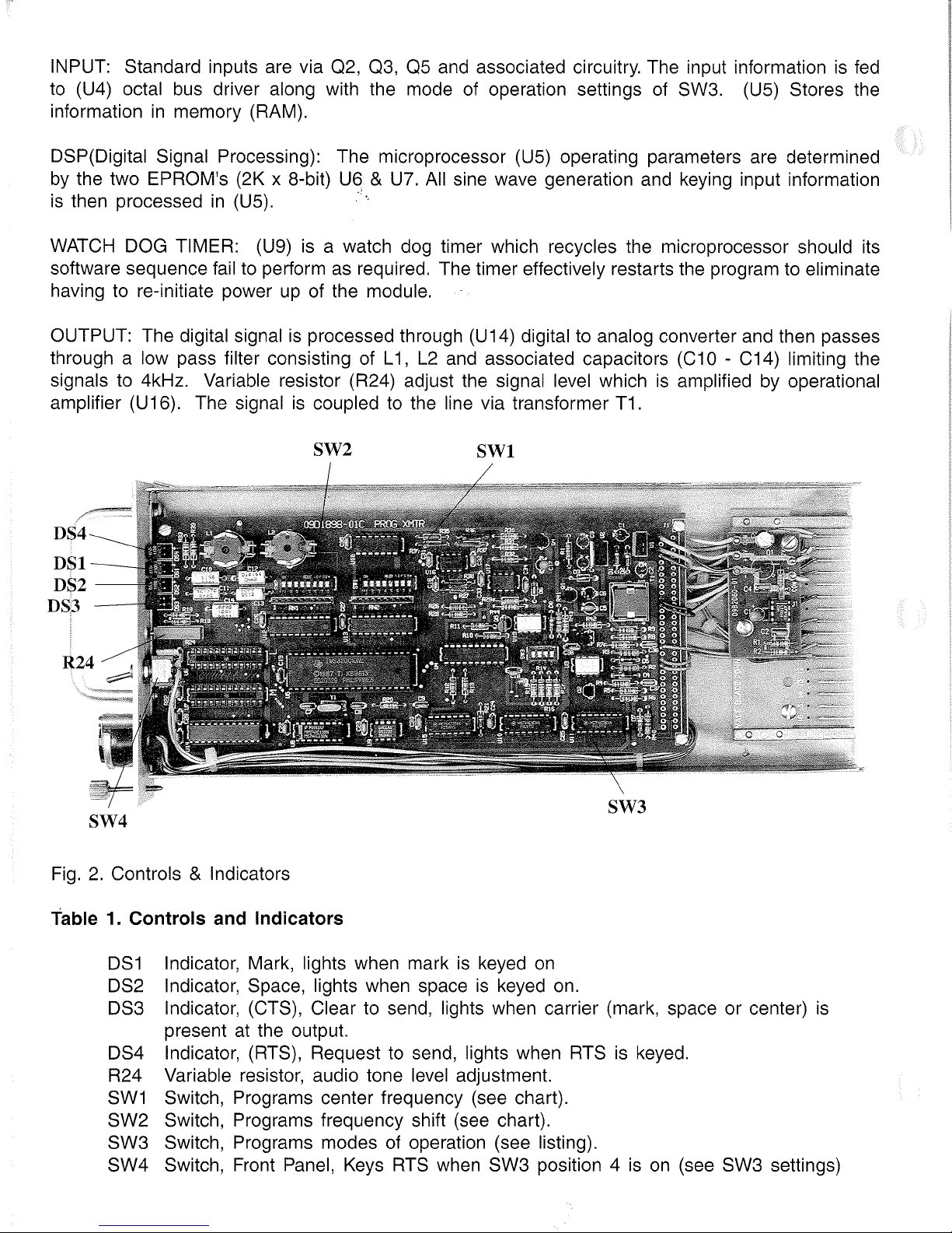
INPUT: Standard inputs are via
02, 03,
OS
and associated circuitry. The input informationisfed
to
(U4) octal
bus
driver along with the mode of operation settings
of
SW3.
(US)
Stores the
information
in
memory (RAM).
DSP(Digital Signal Processing): The microprocessor
(US)
operating parameters are determined
by
the two EPROM's (2K x 8-bit) U6 &
U7.
Ali
sine wave generation and keying input information
is
then processed
in
(US)."',
WATCH
DOG TIMER: (U9)
is
a watch dog timer which recycles the microprocessor should its
software sequence fail to perform
as
required. The timer effectively restarts the program to eliminate
having to re-initiate power
up
of the module.
OUTPUT: The digital signal
is
processed through (U14) digital to analog converter and then passes
through a low pass filter consisting of L
1,
L2
and associated capacitors (C10 - C14) Iimiting the
signals to 4kHz. Variable resistor (R24) adjust the signal level which
is
amplified by operational
amplifier (U16). The signal
is
coupled to the line via transformer T1.
SW2
DS4
DSl--
DS2
DS3
SW4
Fig.
2.
Controls & Indicators
Table 1. Controls and Indicators
SWl
SW3
DS1
Indicator, Mark, lights when markiskeyed
on
DS2 Indicator, Space, lights when space
is
keyed on.
DS3 Indicator, (CTS), Clear to send, lights when carrier (mark, space or center)
is
present
at
the output.
DS4 Indicator, (RTS), Request to send, lights when
RTSiskeyed.
R24 Variable resistor, audio tone level adjustment.
SW1
Switch, Programs center frequency (see chart).
SW2 Switch, Programs frequency shift (see chart).
SW3 Switch, Programs modes
of
operation (see listing).
SW4 Switch, Front Panel, Keys
RTS
when SW3 position 4ison
(see SW3 settings)

@@
}
SPACE
KEYING
}.MARK KEYING
+12VDC INPUT
l----f-
COMMON
>---+-}
PHONE
LINE
OUTPUT
>---+-} RTS/CARRIER KEYING
11
@{,:;\
®
W
\SJ@
@
@@
IT-30DSP
Fig.
3.
Terminai Block (TB1)
INSTALLATION:
UNPACKING: This equipment may
be
supplied loose, mountedinan
individual chassis ' stacked
interconnected chassis, or as part of a rack or cabinet. Follow the procedure for the type of system
supplied.
Loose and/or equipment mounted
in
an
individual chassis will be packedinits own shipping carton.
Inspect the carton for possible damage
in
transit. Open each carton carefully and remove the
contents. Inspect the equipment for possible damage. Verify
ali
items of value have been removed
prior to discarding any packing materia!.
NOTE:
Itissuggested the carton
be
retained for possible onward shipment.
Interconnected chassis or equipment supplied
in
racks or cabinets will
be
suppliedinspecial boxes,
wood crates, or if shipped via air-ride
van
without any case. Inspect the crate or other packing for
possible damage
in
transit. Carefully remove the equipment from the container and inspect it for
possible damage. Verify
ali
items of value have been removed from the crate prior
to
discarding
any packing material and refer to the note above.
Should transit damage
be
found please notify INIVEN immediately.
MOUNTING: After unpacking follow the appropriate mounting procedure.
Loose module: (The following
is
for new installations - replacementofan
existing module will
have
the termi
nai
block already mounted. Each new unitisshipped with the terminai block plugged into
the rear of the unit. There are also four 6-32 screws shipped with
it
to mount the terminai block
to
the chassis. Locate the desired position within the chassis for which the moduleisto
be
placed.
Viewing the chassis from the front, the recommended arrangement
is
a power supply
on
the extreme
left then followed
by
transmit and or receive modules working towards the right of the chassis.

Interconnected Chassis or equipment mounted
on
shipping rails
is
to
be
mounted similar
to
an
individual chassis. When shipping rails are provided the equipmentisto
be
placed near the desired
location. Remove the screws holding the shipping rails and then remove the rails. Slide the equipment
into the rack or cabinet and secure it with proper screws for the mating hardware being used.
Tighten ali screws.
Systems provided
in
a rack or cabinet from the factory must
be
secured
to
the floor or wall
as
required. Mounting hardwareisnot sqpplied due to the various surfaces
and
mounting methods.
CAUTION: EQUIPMENT MOUNTED
IN
SWING RACK TYPE CABINETS MUST
BE
SECURED
TO
THE MOUNTING SURFACE PRIOR
TO
OPENING THE SWING RACK
TO
PREVENT THE
CABINET FROM FALLlNG.
VENTILATION: Proper ventilation
is
required for most electronic equipment. Enclosed cabinets or
rooms where this equipment
is
mounted should
be
kept at temperatures within the limits of the
equipment. Operation above these limits may affect reliability.
ELECTRICAL CONNECTIONS: User connections are made via the terminai blocks
on
the rear
of
the chassis. Each unit
in
the Gen 1 SERIES
of
equipment will contain these connections
in
the
instruction manual for the specific individual module.
On
equipment supplied wired from the factory
or
on
wired chassis and cabinets
an
"as supplied" drawing will
be
included with the equipment.
External wiring should
be
in
accordance with the "as supplied" drawing when supplied.
For safety reasons power
on
the leads to
be
connected to the unit are to be de-energized
during installation.
Methods of making the wiring connections to the terminai blocks vary and based
on
local practice.
Itissuggested number 20
AWG
size insulated wire, stripped portion tinned,
be
used. Approximately
1/4" of the insulation
is
to
be
removed and insertedinthe terminai block.
Module power and tone lines may
be
daisychained should the application require.
Tighten all connections and insure exposed wires do not touch each other or the chassis.
INITIAL STARTUP & LEVEL CHECKS:
FREQUENCY SELECTION: With the module removed from the chassis. Select the desired
bandwidth and center frequency from the enclosed charts. Refer to figure 2 for switch location.
EXAMPLE: For
an
85
baud channel at 1615
Hz
center frequency, set SW2 position 3 to "ON"
(only a single position within SW2
is
to be "ON"
at
any one time). Set
SW1
positions
1,
4,
& 7
to "ON" (be sure
all
other positions
on
SW1
are "OFF").
MODE OF OPERATION: Set SW3 to the desired mode of operation
as
detailed below. Refer to
figure 2 for switch location.

SWITCH SW3 SETTINGS:
Ali Positions "OFF": 3F Operation. Keying the Mark input produces a Mark frequency out,
keying the Space input provides a Space frequency
outo
The center frequency will
be
output
when the inputisidle.
Position 1 "ON" only: 3F Operation, Inverted Output. Keying the Mark input produces a Space
frequency out, keying the Space input produces a Mark frequency
outo
The center frequency
will
be
output when the inputisidle.
Position 2 "ON" only: 2F Operation. Keying the Mark input produces the Mark frequency when
keyed. The Space frequency
is
output when the inputisidle. The keying leads should
be
on
the Mark input.
00
not use this option with position 3inthe "ON" position.
Position 3 "ON" only: 3F Operation, FLASHER. The transmitter will shift at 20msec intervals
between Mark and Space when the Mark and Space inputs are keyed at the same time. (This
operation will not function if the position 2
isinthe "ON" position).
Position 4 "ON" only: (RTS). When position 4
is
on,
the front panel switchisactivated. When
position 4
isinthe off position, the front panel switch will not
be
able
to
turn off the output(s).
RTS
can also
be
keyed from the
RTS
input
on
the rear terminai block when the front panel
switch (SW4)
is
in
the "OFF" position. This option may
be
used
in
all modes.
Positions 1
& 2 "ON": 2F operation, Inverted Output. Keying the Mark input produces a Space
frequency output. The Mark frequency
is
output when the inputisidle. The keying leads should
be
on
the Mark input.
00
not use this option with position 3inthe "ON" position.
ADJUSTMENTS: The transmitter contains a front panel LEVEL adjustment (R24) (see figure 2 for
location). Each transmitter
is
shipped from the factory with the level adjustment set at
-6
dBm,
which
is
adequate for most applications.
The following equipment
is
recommended to perform the initial startup
and
level
checks
at:
1.
Digital multimeter with dB readout function; Fluke 8060A or equivalent.
2.
Flatblade screw driver with 1/8 inch wide tip or potentiometer adjustment too!.
3.
Optionai - Card Extender.
WARNING:
00
NOT INSERT THE UNIT INTO A RACK WITH THE POWER ON.
INITIAL SETTINGS: With the power (+12Vdc) and phone line wired to the terminai blocks
on
the
rear of the chassis, connect the test leads of the multimeter (dB mode) across the "tone out"
on
the terminai block.
Turn
on
the power and note the reading
on
the multimeter (the tone output
on
the terminai block should
be
connected to the line or if this
is
not possible, terminated
in
a
600 ohm resistor). Adjust R24(LVL ADJ) with a screwdriver or adjustment tool to the desired level.
Only one transmitter should be
on
the line during this adjustment or a composite level will
be
read, which
is
not a true reading of the transmitter output level. The "as set" level should
be
recorded for future reference.

When two or more transmitters are connected on one communications line, each individual
transmitter level should be adjusted at a reduced level
in
order for the combined (composite)
signals not to exceed the desired output level. Refer to the chart below for recommended levels
referenced to 0 dBm. The recommended dBm levels may also
be
used as reference for any
desired level setting
in
dB.
-,
"
MULTIPLE TONE
OUTPUT LEVELS
Number af dB RMS V
Channels
- Level
600 n
1 0
0.7746
2
-3 0.5484
3
-4.8 0.4457
4
-6
0.3882
5
-7
0.3460
6
-7.8
0.3156
7 -8.5 0.2911
8
-9
0.2748
9
-9.5 0.2595
10 -10 0.2449
11
-10.4 0.2339
12 -10.8
0.2234
13
-11.1
0.2158
14
-11.5 0.2061
15 -11.8 0.1991
16
-12
0.1946
17 -12.3
0.1880
18 -12.5 0.1837
19 -12.8 0.1774
20 -13 0.1734
21
-13.2
0.1695
22 -13.4
0.1656
23 -13.6 0.1618
24 -13.8
0.1582
EXAMPLE: For two transmitters with a desired composite level of
-6
dBm, reduce the desired
level of each transmitter by 3 dB (from the chart below) and set each to
-9
dBm.
ALL
SAFETY PROCEDURES ARE TO BE STRICTLY ADHERED
TO
AND ONLY QUALlFIED
MAINTENANCE, OPERATORS, OR SERVICE PERSONNEL ARE TO PERFORM
WORK
ON THIS
EQUIPMENT.
L1FE
THREATENING VOLTAGES AND CURRENTS ARE PRESENT WITHIN THIS
EQUIPMENT. OBTAIN
ALL
REQUIRED APPROVALS PRIOR
TO
PLACING IN OR OUT OF
SERVICE. ANY UNAUTHORIZED MODIFICATIONS TO THIS EQUIPMENT
WILL
VOID THE
WARRANTY.
NOTE:
In
the event a replacement module is being installed check all switch settings prior to
installation. Comparison with the removed module is one convenient method.

FOR 50 BAUD
OPERATLON
SET POSITION 1 OF SW2 "ON"
To
Obtain Center
Set Listed Positions
Freq.
Hz
of
SW1
to
"ON"
365
4
465
1,4
565
2,4
665
1,2,4
765 3,4
865
1,3,4
965
2,3,4
1075
1,2,3,4
1175
5
1275 1,5
1375 2,5
1475
1,2,5
1575
3,5
1675
1,3,5
1775 2,3,5
1875
1,2,3,5
2000
4,5
2100
1,4,5
2200
2,4,5
2300
1,2,4,5
2400
3,4,5
2500
1,3,4,5
2600
2,3,4,5
2700
1,2,3,4,5
2800 6
2900 1,6
3000
2,6
3100
1,2,6
3200 3,6
3300
1,3,6
3400 2,3,6
3500
1,2,3,6
FOR 60
BAUD
OPERATION
SET POSITION 2 OF SW2 "ON"
To
Obtain Center Set Listed Positions
Freq.
Hz
of
SW1
to
"ON"
420
4,6
540
1,4,6
660
2,4,6
780
1,2,4,6
900
3,4,6
1020
1346
1140
2,3,4,6
1260
1,2,3,4,6
1380 5,6
1500
1,5,6
1620 2,5,6
1740
1,2,5,6
1860
3,5,6
1980
1,3,5,6
2100
2,3,5,6
2220
1,2,3,5,6
2340
4,5,6
2460
1,4,5,6
2580
2456
2700
1,2,4,5,6
2820
3456
2940 1
3456
3060
23456
3180
123456
3300
7
3420
1,7

FOR
85
BAUD OPERATION
SET POSITION 3 OF SW2 "ON"
Ta Obtain Center Set Listed Pasitians
Freq. Hz af
SW1
ta"'mN"
425
27
595 1 2 7
765 3,7
935
1,3,7
1105
2,3,7
1275
1,2,3,7
1445
4,7
1615
1,4,7
1785
2,4,7
1955
1,2,4,7
2125
3,4,7
2295
1,3,4,7
2465
2,3,4,7
2635
1,2,3,4,7
2805
5,7
2975
1,5,7
3145
2,5,7
3315
1,2,5,7
3485 3,5,7
FOR 120 BAUD OPERATION
SET POSITION 4 OF SW2
"ON"
Ta Obtain Center
Set Listed Pasitians
Freq. Hz
af
SW1ta"ON"
480
1 3,5,7
720
2,3,5,7
960
1,2,3,5,7
1200
4,5,7
1440
1,4,5,6
1680
2,4,5,7
1920
1,2,4,5,7
2160
3,4,5,7
2400
1,3,4,5,7
2640
2,3,4,5,7
2880
1,2,3,4,5,7
3120
6,7
3360
1,6,7
FOR 170 BAUD OPERATION
SET POSITION 5 OF SW2 "ON"
Ta Obtain Center
Set Listed Pasitians
Freq. Hz
af
SW1ta"ON"
850
267
1190 1
267
1530
367
1870
1,3,6,7
2210
2,3,6,7
2550
1,2,3,6,7
2890
4,6,7
3230
1,4,6,7
FOR 240 BAUD OPERATION
SET POSITION 6 OF SW2
"ON"
Ta
Obtain Center
Set
listed
Pasitians
Freq. Hz
af
SW1ta"ON"
600
2467
1080
1
2467
1560
3467
2040
1,3,4,6,7
2520
2,3,4,6,7
3000
1,2,3,4,6,7
FOR 300
BAUD
OPERATION
SET POSITION 7 OF SW2
"ON"
Ta Obtain Center Set
listed
Pasitians
Freq. Hz af
SW1ta"ON"
1020 5,6,7
1700
1,5,6,7
2380
2,5,6,7
3060
1,2,5,6,7
FOR 600 BAUD OPERATION
SET POSITION 8 OF SW2
"ON"
Ta Obtain Center
Set Listed Pasitians
Freq. Hz
af
SW1ta"ON"
1360
3,5,6,7
2720
1,3,5,6,7

Circuit
Symbol
C14,6
C5,
18-35
C7-9
C10
C11
C12
C13
C14
C16
C17
C36, 37
R1
R2,
3
R4,
7
R5,
8
R6,
9
R10-13,
32
R14-17, 28
R18, 19, 23
R20
R21
R22
R24
R26
R27
R29
R30
R31
R34-36
R37
01,2,4, 5
03
06
DS14
01-5
U1
U2
U3
U4
U6,
7
U5
U10,
11
U8
U9
U 12, 13
U15
U14
U16
U17
U18
Table
1.
Replaceable parts IT-30DSP
Description
CAPACITORS:
Capacitor, tantalum dipped, 1
uF,
20V,
+/-10%
Capacitor;.ceramic,
.1
uF,50V,
+/-20%
Capacitor, ceramic,
18pF,
100V,
+/-5%
Capacitor, metalized polycarbonate,
.01
uF,
100V,
+/--3%
Capacitor, metalized polycarbonate, .0082uF,
100V,
+/-2%
Capacitor, metalized polycarbonate, .027uF, 100V, +/-3%
Capacitor, metalized poJycarbonate, .0022uF,
100V,
+/-3%
Capacitor, metalized polycarbonate, .022uF,
100V,
+/-3%
Capacitor, ceramic,
100pF,
50V,
+/-5%
Capacitor, tantalum,
4.7uF,
35V,
+/-10%
Capacitor, ceramic,
330pF,
100V, +/-5%
RESISTORS:
Resistor, carbon, 6.2K, 1/4 watt, +/-5%
Resistor, carbon, 5.6K, 1/4 watt, +/-5%
Resistor, carbon, 50K, 1/4 watt, +/-5%
Resistor, carbon, 20K, 1/4 watt, +/-5%
Resistor, carbon, 1.0K, 1/4 watt, +/-5%
Resistor, carbon, 100K, 1/4 watt, +/-5%
Resistor, carbon, 10K, 1/4 watt, +/-5%
Resistor, carbon, 680(, 1/4 watt, +/-5%
Resistor, carbon, 4.7K, 1/4 watt, +/-5%
Resistor, carbon, 3.9K, 1/4 watt, +/-5%
Resistor, carbon, 2.4K, 1/4 watt, +/-5%
Resistor, variable, 50K, 3/4 watt, 10 turn
Resistor, metal film, 1.18K, 1/4 watt,
+/-1
%
Resistor, metal film, 10K, 1/4 watt,
+/-1
%
Resistor, carbon, 33K, 1/4 watt, +/-5%
Resistor, carbon, 27K, 1/4 watt, +/-5%
Resistor, carbon, 220K, 1/4 watt, +/-5%
Resistor, metal film, 100K, 1/4 watt,
+/-1
%
Resistor, metal film, 105K, 1/4 watt, +/-1%
SEMICONDUCTORS:
Diode, avalanche,
400V,
1A
Diode, zener, 5.6V
Diode, general purpose
LEO,
red
Transistor, NPN
NOT USED
IN
STANDARD APPLlCATIONS
Negative voltage regulator, 5 Vdc
Dual phototransistor
Octel/bus driver, non-inverting
EPROM, 2K x 8bit
Digital signal processor (DSP)
Counter, binary resettable SYNC/ASYNC
3 line to 8 line decoder/demultiplexer
Watchdog timer
Octal inverting buffer, 3 state
Ouad 2input nand schmidt trigger
14bit DAC
Dual operational amplifier
Dual amplifier
Hex inverter
INIVEN Part
Number
DT20V105K
CM-Z5U-D-104-M
CM-NPO-E-180-J
MPC32E103H
MPC32E822G
MPC32E273H
MPC32E222H
MPC32E223H
CM-NPO-D-101-J
DT35V475K
CM-NPO-D-331-J
RCF07J622
RCF07J562
RCF07J503
RCF07J203
RCF07J102
RCF07J104
RCF07J103
RCF07J681
RCF07J472
RCF07J392
RCF07J214
3008P-1-503
RN55D1181 F
RN55D1002F
RCF07J333
RCF07J273
RCF07J224
RN55D1003F
RN55D1053F
1N4004
1N752A
1N914
550-1106-RED
2N4401
MC79M05CT
MCT6
MM74HC244N
CY7C291-50WC
TMS320C10NL
MM74HC161N
MM74HC138N
DS1232
MM74HC240N
MM74HC132N
AD7840JN
TL0821P
TL081CT
MM74HC04N

Circuit
Symbol
T1
SW1,2
SW3
SW4
Y1
Description
MISCELLANEOUS COMPONENTS:
Transformer, INIVEN
Switch, DIP 8 position
Switch, push
b1:.l,tton
Switch, toggle '
Crystal, quartz,20 MHz.
INIVEN Part
Number
CC1992-00
ADF-08
ADF-04
7101SYZB
SE200-AS
Table1.Replaceable Parts, Voltage Converter board:
Circuit
Symbol
C4
C1
C2
C3
R3
R1
R2
01
Ui
Description
CAPACITORS:
Capacitor, ceramic,
0.1
uF,
50V,
+/-20%
Capacitor, tantalum,
10uF,
35V,
+/-20%
Capacitor, ceramic, 0.047uF,
50V,
+/-10%
Capacitor, electrolytic,
100uF,
35V,
+/-10%
RESISTORS:
Resistor, carbon, 2.2K, 1/4 watt, +/-5%
Resistor, carbon, 20K, 1/4 watt, +/-5%
Resistor, carbon, 200K, 1/4 watt, +/-5%
SEMICONDUCTORS:
Transistor, NPN
Switched capacitor voltage converter
INIVEN Part
Number
CM-Z5U-D-104M
DT35VI06M
CM-X7R-D-473K
ER35V107
RCF07J222
RCF07J203
RCF07J204
2N4401
LT1054CN8

NOTES

WARRANTY AGREEMENT
We
hereby certify that the INIVEN product line carries a warranty for any part whicll
fails during normal operation or service for
12
Years.
A defective part should
be
returned
to the factory, shipping charges prepaid, for repair f.o.b. Somerville, New Jersey.
In
case
INIVEN cannot promptly return the unit
to
you,itwill endeavor to provide a loaner until
the repair or replacement
is
returned
to
you. Any unauthorized repairs or modifications
will void the warranty. This warranty
is
contingent upon the commercial availability of parts
as purchased
by
INIVEN. However,
in
the event that failureisless than two years from
the date of delivery of the product, INIVEN will accept full responsibility.
INIVEN 5 Columbia
Rd.
Somerville,
NJ
08876
PRINTED
IN
U.S.A.
INIVEN TM 5 Columbia
Rd.
Somerville,
NJ
08876
908-722-3770
FAX
908-722-5461 800-526-3984
 Loading...