

INIM Electronics SmartLiving 10100L, SmartLiving 515, SmartLiving 1050L, SmartLiving 1050L/G3, SmartLiving 10100L/G3 Installation And Programming Manual
...
Installation and programming manual
1
SMARTLIVING
Anti-intrusion control panels and security systems
INSTALLATION AND
PROGRAMMING MANUAL
EN 50131-1
EN 50131-3
EN 50131-6
EN 50131-10
EN 50136-1
EN 50136-2
EN 50130-4
EN 50130-5
CEB T014

2
Anti-intrusion control panels
Warranty
INIM Electronics s.r.l. (Seller, Our, Us) warrants the original purchaser that this
product shall be free from defects in materials and workmanship under normal
use for a period of 24 months. As INIM Electronics s.r.l. does not install this
product directly, and due to the possibility that it may be used with other
equipment not approved by Us; INIM Electronics s.r.l. does not warrant against
loss of quality, degradation of performance of this product or actual damage that
results from the use of products, parts or other replaceable items (such as
consumables) that are neither made nor recommended by INIM Electronics.
Seller obligation and liability under this warranty is expressly limited to repairing
or replacing, at Seller's option, any product not meeting the specifications. In no
event shall INIM Electronics s.r.l. be liable to the purchaser or any other person
for any loss or damage whether direct of indirect or consequential or incidental,
including without limitation, any damages for lost profits, stolen goods, or claims
by any other party caused by defective products or otherwise arising from the
incorrect or otherwise improper installation or use of this product.
This warranty applies only to defects in parts and workmanship relating to normal
use. It does not cover:
• damage arising from improper maintenance or negligence
• damage caused by fire, flood, wind or lightning
•vandalism
• fair wear and tear
INIM Electronics s.r.l. shall, at its option, repair or replace any defective products.
Improper use, that is, use for purposes other than those mentioned in this
manual will void the warranty. Contact Our authorized dealer, or visit our website
for further information regarding this warranty.
Limited
warranty
INIM Electronics s.r.l. shall not be liable to the purchaser or any other person for
damage arising from improper storage, handling or use of this product.
Installation of this Product must be carried out by qualified persons appointed by
INIM Electronics. Installation of this Product must be carried out in accordance
with Our instructions in the product manual.
Copyright
The information contained in this document is the sole property of INIM
Electronics s.r.l. No part may be copied without written authorization from INIM
Electronics s.r.l.
All rights reserved.
European
Directive
compliance
Hereby INIM Electronics s.r.l. declares that the SmartLiving series of intrusioncontrol panels, the Air2 series of devices and the SmartLinkAdv product are in
compliance with the essential requirements and other relevant provisions of
Directive 1999/5/CE.
Moreover, INIM Electronics s.r.l. also declares that all other devices mentioned in
this manual are in compliance with the essential requirements and other relevant
provisions of Directive 2004/108/CE.
The full declarations of conformity can be found at URL:
www.inim.biz/certifications
Leading-edge
systems
(DM37/08)
The devices described in this manual, depending on the settings selected during
the installation phase and the implementation of the concepts illustrated in this
guide, allow you to create an Intrusion Detection and Hold-up Alarm System (I &
HAS) compliant with EN 50131-1: 2006 + A1: 2009, safety grade 3 (at highest)
and an alarm transmission system (ATS) compliant with EN 50136-1: 2012 in
category ATS6 (at highest SP6 or DP4).
The devices described are compliant with European standards EN 50131-3: 2009
(in reference to control and indicating equipment - CIE), EN 50131-6: 2008 + A1:
2014 (in reference to power supplies - PS), EN 50131- 10: 2014 and EN 501362: 2013 (in reference to transceivers on supervised sites - SPT).
As a support to the design, planning, operation, installation, commissioning and
maintenance of intrusion alarm systems installed in buildings, the following
regulatory documents should be consulted: CEI 79-3 and CEI CLC / TS 50131-7.
Depending on the State where the components described are installed, certified
compliance with local laws and regulations may be required.

Installation and programming manual
3
Table of
contents
Warranty . . . . . . . . . . . . . . . . . . . . . . . . . . . . . . . . . . . . . . . 2
Limited warranty . . . . . . . . . . . . . . . . . . . . . . . . . . . . . . . . . 2
Copyright . . . . . . . . . . . . . . . . . . . . . . . . . . . . . . . . . . . . . . 2
European Directive compliance. . . . . . . . . . . . . . . . . . . . . . . . 2
Leading-edge systems (DM37/08) . . . . . . . . . . . . . . . . . . . . . 2
Table of contents . . . . . . . . . . . . . . . . . . . . . . . . . . . . . . . . . 3
About this manual . . . . . . . . . . . . . . . . . . . . . . . . . . . . . . 5
0-1 Terminology . . . . . . . . . . . . . . . . . . . . . . . . . . . . . . . . . . . . . . . . . 5
0-2 Graphic conventions. . . . . . . . . . . . . . . . . . . . . . . . . . . . . . . . . . . . 5
Chapter 1 General information . . . . . . . . . . . . . . . . . . . . . . . . . . . . . 6
1-1 Manufacturer's details . . . . . . . . . . . . . . . . . . . . . . . . . . . . . . . . . . 6
1-2 Description of the product and various models . . . . . . . . . . . . . . . . . 6
1-3 Certified items and conformity. . . . . . . . . . . . . . . . . . . . . . . . . . . . . 6
1-4 Patents Pending. . . . . . . . . . . . . . . . . . . . . . . . . . . . . . . . . . . . . . . 7
1-5 Manuals . . . . . . . . . . . . . . . . . . . . . . . . . . . . . . . . . . . . . . . . . . . . 7
1-6 Operator Qualifications . . . . . . . . . . . . . . . . . . . . . . . . . . . . . . . . . . 8
1-7 Access Levels . . . . . . . . . . . . . . . . . . . . . . . . . . . . . . . . . . . . . . . . 8
1-8 Conventions – Glossary . . . . . . . . . . . . . . . . . . . . . . . . . . . . . . . . . 8
Chapter 2 The control panel and peripherals . . . . . . . . . . . . . . . . . . . 9
2-1 SmartLiving intrusion control panels . . . . . . . . . . . . . . . . . . . . . . . . 9
2-2 Environmental Conditions . . . . . . . . . . . . . . . . . . . . . . . . . . . . . . . . 14
2-3 Peripherals . . . . . . . . . . . . . . . . . . . . . . . . . . . . . . . . . . . . . . . . . . 15
2-4 SmartLAN ethernet interface. . . . . . . . . . . . . . . . . . . . . . . . . . . . . . 25
2-5 AUXREL32 Power distribution board . . . . . . . . . . . . . . . . . . . . . . . . . 26
Chapter 3 Installation . . . . . . . . . . . . . . . . . . . . . . . . . . . . . . . . . . . 27
3-1 Installing the control panel . . . . . . . . . . . . . . . . . . . . . . . . . . . . . . . 27
3-2 Connecting peripherals . . . . . . . . . . . . . . . . . . . . . . . . . . . . . . . . . . 33
3-3 Addressing the peripherals . . . . . . . . . . . . . . . . . . . . . . . . . . . . . . . 38
3-4 Auto-enrolling peripherals. . . . . . . . . . . . . . . . . . . . . . . . . . . . . . . . 41
3-5 Wiring and balancing alarm detectors. . . . . . . . . . . . . . . . . . . . . . . . 41
3-6 Wiring and balancing rollerblind/shock sensors . . . . . . . . . . . . . . . . . 43
3-7 Connecting wireless detectors . . . . . . . . . . . . . . . . . . . . . . . . . . . . . 44
3-8 Learn zone balancing . . . . . . . . . . . . . . . . . . . . . . . . . . . . . . . . . . . 45
3-9 Connecting the outputs . . . . . . . . . . . . . . . . . . . . . . . . . . . . . . . . . 45
3-10 Installing add-on boards . . . . . . . . . . . . . . . . . . . . . . . . . . . . . . . . . 46
3-11 IP and Internet Connectivity . . . . . . . . . . . . . . . . . . . . . . . . . . . . . . 47
Chapter 4 First power up . . . . . . . . . . . . . . . . . . . . . . . . . . . . . . . . . 50
Chapter 5 Installation project via the SmartLeague . . . . . . . . . . . . . . 51
5-1 The SmartLeague software program . . . . . . . . . . . . . . . . . . . . . . . . 51
5-2 Using the software program . . . . . . . . . . . . . . . . . . . . . . . . . . . . . . 52
5-3 Creating a project layout . . . . . . . . . . . . . . . . . . . . . . . . . . . . . . . . 52
Chapter 6 Inim Cloud . . . . . . . . . . . . . . . . . . . . . . . . . . . . . . . . . . . 54
6-1 User levels . . . . . . . . . . . . . . . . . . . . . . . . . . . . . . . . . . . . . . . . . . 54

4
Anti-intrusion control panels
6-2 Web interface . . . . . . . . . . . . . . . . . . . . . . . . . . . . . . . . . . . . . . . . 55
6-3 Control panel registration . . . . . . . . . . . . . . . . . . . . . . . . . . . . . . . . 56
6-4 Control panel connection . . . . . . . . . . . . . . . . . . . . . . . . . . . . . . . . 57
Chapter 7 Options and programming methods . . . . . . . . . . . . . . . . . . 58
7-1 Introduction . . . . . . . . . . . . . . . . . . . . . . . . . . . . . . . . . . . . . . . . . 58
7-2 Accessing the Installer menu . . . . . . . . . . . . . . . . . . . . . . . . . . . . . 58
7-3 Programming via the SmartLeague software. . . . . . . . . . . . . . . . . . . 59
7-4 Fast programming from the keypad (Wizard) . . . . . . . . . . . . . . . . . . 59
7-5 Panel options . . . . . . . . . . . . . . . . . . . . . . . . . . . . . . . . . . . . . . . . 60
7-6 Terminals . . . . . . . . . . . . . . . . . . . . . . . . . . . . . . . . . . . . . . . . . . . 64
7-7 Zones . . . . . . . . . . . . . . . . . . . . . . . . . . . . . . . . . . . . . . . . . . . . . 65
7-8 Outputs . . . . . . . . . . . . . . . . . . . . . . . . . . . . . . . . . . . . . . . . . . . . 70
7-9 Walk test . . . . . . . . . . . . . . . . . . . . . . . . . . . . . . . . . . . . . . . . . . . 71
7-10 Telephone. . . . . . . . . . . . . . . . . . . . . . . . . . . . . . . . . . . . . . . . . . . 72
7-11 Events . . . . . . . . . . . . . . . . . . . . . . . . . . . . . . . . . . . . . . . . . . . . . 73
7-12 Timer. . . . . . . . . . . . . . . . . . . . . . . . . . . . . . . . . . . . . . . . . . . . . . 83
7-13 Partitions . . . . . . . . . . . . . . . . . . . . . . . . . . . . . . . . . . . . . . . . . . . 84
7-14 User Codes . . . . . . . . . . . . . . . . . . . . . . . . . . . . . . . . . . . . . . . . . . 85
7-15 Installer codes . . . . . . . . . . . . . . . . . . . . . . . . . . . . . . . . . . . . . . . 87
7-16 Keys . . . . . . . . . . . . . . . . . . . . . . . . . . . . . . . . . . . . . . . . . . . . . . 87
7-17 Arming scenarios. . . . . . . . . . . . . . . . . . . . . . . . . . . . . . . . . . . . . . 89
7-18 Shortcuts . . . . . . . . . . . . . . . . . . . . . . . . . . . . . . . . . . . . . . . . . . . 90
7-19 Expansions . . . . . . . . . . . . . . . . . . . . . . . . . . . . . . . . . . . . . . . . . . 90
7-20 Keypads . . . . . . . . . . . . . . . . . . . . . . . . . . . . . . . . . . . . . . . . . . . . 91
7-21 Readers . . . . . . . . . . . . . . . . . . . . . . . . . . . . . . . . . . . . . . . . . . . . 92
7-22 Sounders . . . . . . . . . . . . . . . . . . . . . . . . . . . . . . . . . . . . . . . . . . . 93
7-23 Language . . . . . . . . . . . . . . . . . . . . . . . . . . . . . . . . . . . . . . . . . . . 93
7-24 Messages . . . . . . . . . . . . . . . . . . . . . . . . . . . . . . . . . . . . . . . . . . . 94
7-25 Default settings. . . . . . . . . . . . . . . . . . . . . . . . . . . . . . . . . . . . . . . 94
7-26 User functions. . . . . . . . . . . . . . . . . . . . . . . . . . . . . . . . . . . . . . . . 96
7-27 Other parameters . . . . . . . . . . . . . . . . . . . . . . . . . . . . . . . . . . . . . 97
7-28 Activating outputs without authentication. . . . . . . . . . . . . . . . . . . . . 100
7-29 Programming the Nexus. . . . . . . . . . . . . . . . . . . . . . . . . . . . . . . . . 101
7-30 Configuration of graphic maps. . . . . . . . . . . . . . . . . . . . . . . . . . . . . 103
Chapter 8 Compliance with rules in force . . . . . . . . . . . . . . . . . . . . . 104
Chapter 9 Errors and faults . . . . . . . . . . . . . . . . . . . . . . . . . . . . . . . 107
9-1 Faults detected by the control panel . . . . . . . . . . . . . . . . . . . . . . . . 107
9-2 Communication BUS (I-BUS) . . . . . . . . . . . . . . . . . . . . . . . . . . . . . 108
9-3 LED activity . . . . . . . . . . . . . . . . . . . . . . . . . . . . . . . . . . . . . . . . . 108
9-4 Ring Sensitivity . . . . . . . . . . . . . . . . . . . . . . . . . . . . . . . . . . . . . . . 109
9-5 Calibrating the touch-screen . . . . . . . . . . . . . . . . . . . . . . . . . . . . . . 109
Appendix A Technical terminology and Glossary. . . . . . . . . . . . . . . . . . 110
Appendix B Shortcuts at default. . . . . . . . . . . . . . . . . . . . . . . . . . . . . 118
Appendix C Available Icons . . . . . . . . . . . . . . . . . . . . . . . . . . . . . . . . 119
Appendix D Voice messages. . . . . . . . . . . . . . . . . . . . . . . . . . . . . . . . 120
Appendix E Screw Terminals . . . . . . . . . . . . . . . . . . . . . . . . . . . . . . . 122
Appendix F Combination of outputs triggered by events . . . . . . . . . . . . 123
Appendix G SIA Codes . . . . . . . . . . . . . . . . . . . . . . . . . . . . . . . . . . . 124
Notes . . . . . . . . . . . . . . . . . . . . . . . . . . . . . . . . . . . . . . . . . 127

Installation and programming manual
About this manual 5
ABOUT THIS MANUAL
MANUAL CODE
DCMIINE0SLIVINGE
VERSION
6.40
0-1
Terminology
CONTROL PANEL,
SYSTEM, DEVICE
The main supervisory unit or any constituent parts of the SmartLiving intrusion control
system.
LEFT, RIGHT, BEHIND,
ABOVE, BELOW
Directions as seen by the operator when directly in front of the mounted device.
DIALLER
A device which sends voice calls or digital reports to programmed contact numbers in
the event of an alarm.
QUALIFIED PERSONNEL
Persons whose training, expertise and knowledge of the products and laws regarding
security systems, are able to create, in accordance with the requirements of the
purchaser, the most suitable solution for the protected premises.
SELECT
Click on a specific item on the interface (drop-down menu, options box, graphic object,
etc.).
PRESS
Click on a video button, or push a key on the control-panel keypad.
0-2
Graphic conventions
Following are the graphic conventions used in this manual.
Note
The “Note” sections contain important information relating to the text.
ATTENTION!
The “Attention” prompts indicate that total or partial disregard of the procedure could
damage the device or its peripherals.
DANGER!
The “DANGER” warnings indicate that total or partial disregard of the procedure could
injure the operator or persons in the vicinity.
Similarly marked dialogue boxes contain recommendations and/or guidelines which the
manufacturer wishes to call attention to.
Conventions Example Description
Text in italics
Refer to paragraph 0-2
Graphic conventions
Directs you to the title of a chapter, section,
paragraph, table or figure in this manual or
other published reference.
<text> #<AccountCode> Editable field
[Uppercase letter] or [num-
ber]
[A] or [1]
Reference relating to a part of the system or
video object.
BUTTON
, ,
Keypad keys
Info

6 General information
Anti-intrusion control panels
Chapter 1
GENERAL INFORMATION
1-1
Manufacturer's details
Manufacturer: INIM ELECTRONICS s.r.l.
Production plant: Centobuchi, via Dei Lavoratori 10
63076, Monteprandone (AP), Italy
Tel.: +39 0735 705007
Fax: +39 0735 704912
e-mail: info@inim.biz
Web: www.inim.biz
The persons authorized by the manufacturer to repair or replace the parts of this
system have authorization to work on INIM Electronics brand devices only.
1-2
Description of the product and
various models
Description: Intrusion control panel
Models: SmartLiving 505
SmartLiving 515
SmartLiving 1050, SmartLiving 1050/G3,
SmartLiving 1050, SmartLiving 1050/G3,
SmartLiving 10100L, SmartLiving10100L/G3
Standards applied: EN 50131-1:2006 + A1:2009,
EN 50131-3:2009,
EN 50131-6:2008 + A1:2014,
EN 50131-10:2014,
EN 50136-1:2012,
EN 50136-2:2013,
EN 50130-4:2011 + A1:2014,
EN 50130-5:2011,
CEB T014:2013-04 (ed.3)
Certifying body: IMQ S.p.A.
Safety grade: 2 or 3 (in accordance with configurations, refer to table 2-2)
ATS Categories: up to SP6 or DP4 (in accordance with configurations
see table 2-11 and 2-12)
1-3
Certified items and conformity
The SmartLiving control panels and devices described in this manual are IMQ certified Sistemi di sicurezza (IMQ S.p.A.) and conform to the above mentioned standards, when
duly programmed, as described in Chapter 8 - Compliance with rules in force .
The control panel enclosure in capable of housing the following certified items:
• INIM Electronics switching-power supply
• Motherboard (IN082 or IN088)
• SmartLogos30M voice board (accessory item)
• FLEX5/U input/output expansion board (accessory item)
• AUXREL32 relay board (accessory item)
• SmartLAN/SI and SmartLAN/G LAN interface boards (accessory items)
• GSM Nexus and Nexus/G communicators (optional)

Installation and programming manual
General information 7
• IB100/RU BUS isolator board (accessory item)
• ProbeTH thermal-probe kit for battery-charge optimization (accessory item)
• TamperNO tamper-protection kit (accessory item)
• Backup battery, 12V @ 7, 9 or 17Ah (depending on the control panel)
• Motherboard (IN082 and IN088) integrated Type B notification apparatus
The compliance of the control panel is also guaranteed when connected to the following
certified devices:
• FLEX5/P input/output expansion boards
• Joy/MAX, Joy/GR, Aria/HG, Concept/G, nCode/G, Alien/G, Alien/S keypads
• nBy/S outdoor-mount proximity readers
• nBy/X universal-mount proximity readers
• IB100/RP BUS isolator
• Self-powered IB100/A BUS isolator
• nCard access-control card for proximity readers
• Tag for nKey or nBoss proximity readers
• Self-powered sounderflashers for outdoor installation: Ivy, Ivy-F, Ivy-M, Ivy-FM, IvyB, Ivy-BF, Ivy-BM, Ivy-BFM
• Wireless devices AIR2, AIR2-BS200 (transceiver), Air2-IR100 (PIR detector), Air2MC100 (magnetic contact)
• SmartLinkAdv/GP, SmartLinkAdv/G, SmartLinkAdv/P communicators
1-4
Patents Pending
The SmartLiving series of control panels employs the following INIM-patented
technologies.
•
Input/Output Terminals
: each terminal on-board the control panel, keypads and
expansion boards can be configured as either an input or output zone.
• nBy/X proximity reader: this reader has been especially designed to flush-mount
to all models of electrical light-switch backboxes.
• Learn zone balancing: this option allows the control panel to save the balancing
values of all the system zones automatically, thus eliminating the task of typing
them in.
1-5
Manuals
1-5-1
Installation and
programming manual
(this manual)
This manual (not included in the package) can be purchased from your retailer. You (the
installer) should read carefully through it in order to become familiar with all the
components and operating procedures of the SmartLiving system.
In order to provide adequate protection, the installer must adhere to all the
manufacturer's guidelines relating to the active and passive security devices of this
system.
1-5-2
Installation and
programming guide
The guide, supplied with each control panel, provides all the instructions and
illustrations necessary for fast installation and programming of the SmartLiving system.
It provides step by step descriptions of the procedures required for the system wiring,
the various connections and first powerup. It also provides a table for the peripheral
addressing process and a quick guide indicating default parameters and values and how
to program/change them directly from the keypad.
1-5-3
User's manual
The installer should read carefully through the user's manual (supplied with each
control panel). Once the system has been installed, the user manual must given to the
users for consultation. The user must fully understand all the system functions and the
configuration settings.
It is the installer's responsibility to inform the system users that, regardless of its
capabilities, an intrusion alarm system is not a substitute for the necessary precautions
building occupants must take to prevent intrusion.

8 General information
Anti-intrusion control panels
1-6
Operator Qualifications
1-6-1
Installer
The installer is the person (or group of persons) who sets up and programs the entire
security system in accordance with the purchaser's requirements and in respect of the
safety laws in force. As the only individual in contact with system users, it is the
installer's responsibility to instruct them on how to use the security system properly.
Under normal circumstances, the installer is not allowed to arm/disarm the system
without previous authorization from the user. All the system partitions must be
disarmed before accessing the parameter programming phase.
The access code of the installer is a level 3 access code.
1-6-2
User
The users are the occupants of the building where this intrusion control panel is
installed. Only authorized users can access and operate the system.
Thanks to the extreme flexibility of the system, the most common operations can be
carried out without authorization. This operating method must be expressly requested
by the main user, as it considerably lowers the security level of the system and may
cause false alarms, accidental arm/disarm operations, etc.
A system access code can be associated with each user. The programming process
allows you to define the code hierarchy:
• User
• Manager
• Master
The system codes can carry out, in accordance with their assigned level in the
system hierarchy (the “User” being the lowest level), the following operations on all
other codes that are inferior hierarchically:
•• enable/disable
•• change PIN
•• change some of the programming parameters
If the system programming complies with security grade 3 of EN 50131, some partition
arming or delete memory operations, requested from a keypad, may be authorized by
the entry of a level 3 code (installer code) as well as by a user code.
1-7
Access Levels
The normative defines the following system-access levels, regardless of system-access
limitations:
• Level 1 - access by any person (e.g. passer-by)
• Level 2 - user access
• Level 3 - installer or maintenance operator access (authorized by user - level 2)
• Level 4 - manufacturer access
1-8
Conventions – Glossary
In order to understand the terminology used in this manual and improve your
knowledge of this system and its operating procedures, read carefully through the
Technical Terminology – Glossary (refer to Appendix A, Technical terminology and
Glossary).
The appendix contains the definitions of technical terms commonly used in the field of
security, therefore, relevant to the SmartLiving system.

Installation and programming manual
The control panel and peripherals 9
Chapter 2
THE CONTROL PANEL
AND PERIPHERALS
2-1
SmartLiving intrusion control
panels
2-1-1
Package contents
Inside the package you will find:
• Metal box containing the mother board, power-supply (transformer or switching) and
a wired LIVPWR100 board (IN140 for SmartLiving/G3 models)
• User's Manual
• Quick Installation Guide
• Plastic bag:
Items not included in the package:
Dislodgement tamper protection, backup battery, SmartLeague programming software
CD, Installer's manual. These devices are accessory items which must be purchased
separately
.
The SmartLeague programming software and the Installer's manual can be downloaded
free of charge from: www.inim.biz
The control panel data labels are affixed to the outside of the control panel enclosure.
Table 2-1:
Contents of the bag
SmartLiving Control panel models
505
515
1050
1050L
10100L
1050/G3
1050L/G3
10100L/G3
3k9 Ohm 1/4W resistance
10 20
Resistance 6k8 Ohm 1/4W
10 20
Varistors 150Vrms
2
Backup-battery wire
1
Earth connection ring terminal
/1
Thermal probe for optimization of the battery charging
process, based on heat transfer
/1
Screws to secure the frontplate of the metal enclosure
4
“INIM Electronics security-protected area” sticker
Security
system
protected
area

10 The control panel and peripherals
Anti-intrusion control panels
2-1-2
Control panel descriptions
Table 2-2:
Control panels - electrical and mechanical features
SmartLiving Control panel models
505 515 1050 1050/G3 1050L 1050L/G3 10100L 10100L/G3
Voltage
power supply
230V ~ -15% +10% 50/60Hz
nominal output
13.8V
output range
from 9 to 13.8V
Current draw
maximum
0.2A 0.5A 1.1A
of control panel
motherboard
45mA @ 22.5V~ 65mA @ 13.8V
of LIVPWR100
board
/
35mA @
13.8V
/
35mA @
13.8V
/
35mA @
13.8V
SD low voltage
/ 11V/11V/11V
Fault voltage on power outputs
/ 9.8V / 9.8V / 9.8V
Threshold for pro-
tection
from deep dis-
charge
/ 9.5V / 9.5V / 9.5V
from overload
/ 15.4V / 15.4V / 15.4V
Maximum power-supply voltage ripple
350mV 550mV 350mV 550mV 350mV 200mV
PS type
Typ e A
Enclosure Dimensions (W x H x D)
21.5 x 30.5 x 8.5cm 37.5 x 51 x 8.5cm
Weight (without battery)
2.5 Kg 2.2 Kg 5.3 Kg
Security grade
EN50131-3
3
EN50131-6
22232323
Table 2-3:
SD type and current distribution EN 50131-1 compliant
SmartLiving Control panel models
505 515 1050 1050/G3 1050L 1050L/G3 10100L 10100L/G3
SD type
(backup bat-
tery)
rated voltage
12V
maximum
capacity
7Ah 7Ah 7Ah 7Ah 7Ah 17Ah 7Ah 17Ah 17Ah 17Ah
maximum
recharge time
24h (80% charged)
maximum inter-
nal resistance
(R
i max
)
/1.50
ƻ
/1.50ƻ0.50
ƻ
Maximum deliv-
erable current
@ 12V
total
1.2A 3A 3.7A 3A 3.7A 6.2A
for external
loads
530mA 500mA 130mA
500 mA1.35 A130 mA450
mA
1.35A 450mA
Max. current
available on
each +AUX ter-
minal
mother board
900mA 1.35A
LIVPWR100
board
/2A/2A/2A
Maximum deliverable current to
open-collector outputs
150mA 500mA
Table 2-4:
T 014 compliant SD type and current distribution
SmartLiving Control panel models
505 515 1050 1050/G3 1050L 1050L/G3 10100L 10100L/G3
SD type
(backup bat-
tery)
rated voltage
12V
maximum
capacity
9Ah 9Ah 9Ah 9Ah 17Ah 17Ah 17Ah 17Ah
maximum
recharge time
24h (80% charged)
maximum inter-
nal resistance
(R
i max
)
/1.50
ƻ
/1.50ƻ0.50
ƻ
Maximum deliv-
erable current
@ 12V
total
1.2A 3A 3.7A 3A 3.7A 6.2A
for external
loads
330mA 310mA 275mA 635mA 600mA 635mA 600mA
Max. current
available on
each +AUX ter-
minal
mother board
900mA 1.35A
LIVPWR100
board
/2A/2A/2A
Maximum deliverable current to
open-collector outputs
150mA 500mA

Installation and programming manual
The control panel and peripherals 11
The following table shows the maximum number of devices supported by the various
control panel models.
Table 2-5:
Control panel - Main Features
SmartLiving Control panel models 505 515
1050 1050/G3
1050L 1050L/G3
10100L
10100L/G3
Total terminals
515 50 100
Terminals on panel
total
510
configurable as inputs
510
configurable as rollerblind/shock
2
configurable as outputs
05
Total zones
10 30 100 200
Outputs on control-
panel motherboard
total
3
relay
1
open-collector output
2
Partitions
51015
Keypads
(JOY, nCode/G, Concept/G, Alien, Aria)
51015
Voice memo slots
51015
FLEX5 expansions
510 20 40
nBy Readers
10 20 30
Sounderflashers (Ivy-B, Hedera)
10
Air2-BS200 Transceivers
10 20 30
Digital keys and wireless command devices
50 100 150
Possible key combinations
4294967296
IB100 isolators
15
Nexus dialer
1
Codes
30 50 100
Scenarios
30
Timers
10 20
Recordable Events
500 1000
Programmable events
10 30 50
A
B
E
J
F
K
I
D
I
J
J
J
L
H
G
A
B
C
E
F
K
I
D
I
J
J
J
J
L
H
G
SmartLiving 1050/G3SmartLiving 505
SmartLiving 515

12 The control panel and peripherals
Anti-intrusion control panels
Table 2-6:
Control panels - description of parts
Models
SLiving
505
515
1050
1050L
10100L
1050/G3
1050L/G3
10100L/G3
A
Metal enclosure
B
Mother board
C
/ LIVPWR100 board
D
Power adapter (Transformer) Switching power supply
E
Connection terminal board to mains 230V~ - 50/60 Hz
F
Mains cable entry
G
Ground connection screws
H
Frontplate earth wire
I
Wires between transformer and
control panel
Wires between switching-power and control panel
J
Anchor-screw locations for the metal backbox
K
Dislodgement-tamper microswitch location
L
Compartment for backup battery
M
/ Anchor-screw locations for AUXREL32 board
N
/ FLEX5/U expansion board locations
Table 2-7:
Power supplies - description of parts
Models
SLiving
1050
1050L
1050/G3
1050L/G3
10100L 10100L/G3
A
Mains input terminal board
B
Mother board connector
C
Thermal probe connector
D
/ Battery connector / Battery connector
A
B
E
J
F
K
I
D
I
J
J
J
L
C
L
G
H
N
N
N N
N
M
SmartLiving10100L/G3
Switching power supply
SmartLiving 10100L, 10100L/G3
Power supply
SmartLiving1050/1050L,
1050/G3, 1050L/G3
D
A
B
B
A
D
C
C
N
L
230V ~ 50/60 Hz
AC I
nput
N
L
230V ~ 50/60 Hz
AC I
nput

Installation and programming manual
The control panel and peripherals 13
Note
Use of the +AUX terminals on the mother board annuls standard 50131 - 3 compliance.
Table 2-8:
Mother board - description of parts
Models
505
515
1050
1050L
10100L
1050/G3
1050L/G3
10100L/G3
A
/
Connector for power-supply cable between power-supply unit
and control panel
B
Backup-battery connector Do not use
C
Thermal probe connector /
D
Thermal probe (enable/dis-
able) jumper
/
E
Connectors for the SmartLAN power-supply jumper
F
Local I-BUS connector Do not use
G
Maintenance jumper connectors
H
SmartLogos30M voice-board connector
I
Control panel to PC serial cable connector
J
Dislodgement-tamper microswitch connector (accessory item)
K
Open-panel tamper microswitch connector (accessory item)
L
Open-panel tamper microswitch
M
Terminal board
N
Blue and yellow activity LEDs
O
Firmware version label
P
Ground connection screws
Table 2-9:
Mother board - terminal board
n.
icon/identi-
fier
Model
505 515 1050 1050L 10100L
1
Earth connection
2-3
Internal telephone-line connection
4-5 PSTN
Land-line connection (PSTN)
6-7-8-9 + D S -
I-BUS connections
10-11-12 NO NC COM
Voltage-free contacts of the relay output
13
+AUX
+AUX1
12V Ancillary power supply
14-15 OC1 OC2
Open-collector output
16
+AUX
+AUX1
12V Ancillary power supply
17-19-21-
23-25
Power supply negative (earth or GND)
18-20-22-
24-26
T1-T2-T3-
T4-T5
Control panel input terminals: T1, T2, T3, T4 and T5
27
+AUX
+AUX2
12V Ancillary power supply
28-29 AC
Power supply input from
the transformer
28-30-32-
34-36
T6-T7-T8-
T9-T10
Terminals: T6, T7, T8, T9 and T10 of the
control panel
29-31-33-
35
Power supply negative (earth or GND)
37 +AUX3
12V Ancillary power supply
Table 2-10:
LIVPWR100 board - terminal board
n.
icon/identi-
fier
description
1-2-3-4 + D S -
I-BUS connections
5 +AUX1
12V Ancillary power supply
7 +AUX2
9 +AUX3
6-8-10
Power supply negative (earth or GND)
QC Passed
xx/xx/xx
FWINIESLIV15
LBFWINIESLIV15
x.00
SmartLiving 505/515 control-panel
motherboard
D
K
P
6.xx
N
B
C
E
F
G
H
I
J
L
M
O
FWINIESLIV100
LBFWINIESLIV100
x.00
QC Passed
xx/xx/xx
K
O
P
Control panel motherboard
SmartLiving1050/1050L/10100L
1050/G3, 1050L/G3, 10100L/G3
6.xx
A
B
E
F
G
H
I
J
L
M
N

14 The control panel and peripherals
Anti-intrusion control panels
2-1-3
ATS Categories
SmartLiving control panels used alone or together with any of the following described
optional devices constitutes an SPT (Supervised Premises Transceiver) which can be
used to create an ATS (Alarm transmission System) as defined in EN 50136-1 and EN
50136-2 standards.
The following table shows the maximum ATS categories achievable with the SPT
configurations and main communication channel in use, together with the respective
parameters.
2-1-4
Events log memory
The control panel events are saved to a non-volatile semiconductor-memory which
retains data without the need of power.
The electrical characteristics of semiconductor devices diminish over time. However, a
minimum period of 40 years data retention is guaranteed.
2-1-5
I-BUS interconnections
SmartLiving control panels are equipped with a 4-wire BUS for peripheral
interconnections (2 power-supply wire and 2 data exchange wires, refer to paragraph
3-2-1 The I-BUS line wiring).
The intellectual property rights regarding the electrical, structural and protocol features
of the BUS are the sole property of INIM Electronics s.r.l.
The I-BUS is not a RS485 differential BUS.
2-2
Environmental Conditions
SmartLiving control panels must not be installed outdoors and are suitable for operating
under the following conditions:
• Temperature: from -10° to +40°C
• Maximum humidity: 75% (without condensation)
• Environmental class:II
The Joy/GR, Joy/MAX, Aria/HG, nCode/G, Concept/G, Alien/S, Alien/G, IB100, FLEX5,
Nexus and nBy/X peripheral devices are for indoor installation only and operate best
under the following environmental conditions:
• Temperature: from -10° to +40°C
• Maximum humidity: 75% (without condensation)
• Environmental class:II
Table 2-11:
ATS categories based on configurations
SPT Configurations
SPT primary network
interface
ATS Categories
SmartLiving
intrusion
control
panels
Nexus Nexus/G SmartLAN/G
SmartLAN/
SI
Single Path
(SP)
Dual Path
(DP)
X
PSTN 2 /
XX
PSTN or GSM 2 2
XX
GSM/GPRS 6 2
XX
Internet
62
XX
62
XXX
Internet or GSM/GPRS
64
XXX
64
Table 2-12:
ATS Parameters
ATS Categories
Transmission time
Time relation
Replacement
security
Information
security
Operating
mode
Classification
Maximum
values
Single Path
2 D2 (60s) M2 (120s) T2 (25h) S0 I0
Pass-through
6 D4 (10s) M4 (20s) T6 (20s) S2 I3
Dual Path
2 D3 (20s) M3 (60s) T3a (30min) S0 I0
4 D4 (10s) M4 (20s) T5 (90s) S2 I3

Installation and programming manual
The control panel and peripherals 15
The nBy/S reader is suitable for outdoor installation and operates best under the
following conditions:
• Temperature: from -25° to +70°C
• Maximum humidity: 93% (without condensation; for 30 days per year granting
that the relative humidity can touch points of 95% without
being subject to condensation)
• Protection grade:IP 34
• Environmental class:IV
2-3
Peripherals
The control panel I-BUS accommodates the following peripherals:
• JOY/GR, JOY/MAX, Aria/HG, nCode/G, Concept/G, Alien/G e Alien/S keypads
• Readers (nBy/S and nBy/X)
• Expansions (Flex5)
• Transceiver (Air2-BS200)
• Sounderflashers (Ivy-B)
•Isolators (IB100)
• GSM dialer (Nexus)
2-3-1
Joy/GR and Joy/MAX keypads
• Backlit graphic display
• Icon Easy4U interface
•4 indicator LEDs
• Signal buzzer
• Tamper and opening protection
• Mounts to “503” outlets
• 2 Input/Output terminals
Joy/MAX only:
• Thermometer and chronothermostat function
• Microphone and loudspeaker for voice functions
• Built-in proximity reader
Tabella 2-13:
Joy - electrical and mechanical features
Joy keypads models JOY/GR JOY/MAX
Voltage
from 9 to 16V
Typical current draw
70mA 90mA
Terminals configurable as OC outputs
2
Maximum current draw per terminal
150mA
Dimensions (W x H x D)
142 x 116 x 20 mm
Weight
160g 180g
Tabella 2-14:
Joy - description of parts
A
Terminal board
B
Buzzer
C
Microphone (Joy/MAX only)
D
Temperature sensor (Joy/MAX only)
E
Open-tamper microswitch
F
Backlit graphic display
G
Signaling LEDs
H
Antenna (Joy/MAX only)
I
Speaker-wire connector (Joy/MAX only)
J
Wire entry
K
Wall-mo unt scre w l ocati on s
L
Speaker housing
M
Board supports
N
Dislodgement-tamper microswitch screw location
O
Dislodgement-tamper microswitch spring
A
B
C
E
G
H
K
L
D
F
K
K
K
K
K
K
M
M
M
I
J
O
N
JOY keypad board
JOY keypad backbox

16 The control panel and peripherals
Anti-intrusion control panels
Keypad terminals:
Terminals T1 and T2 can be configured as:
• Input (also as Rollerblind or Shock)
•Output
•Double zone
•Supervised Output
The keypad package contains a sticker (to be located under the keypad flip) which can
be used to note down the keypad address or label, its location, the partitions it controls
and any phone-contact numbers.
2-3-2
Aria/HG keypad
• Backlit graphic display
• Icon Easy4U interface
• Brightness sensor
•4 indicator LEDs
• Signal buzzer
• Inertial tamper protection
• Mounts to “503” outlets
• Thermometer and chronothermostat function
• 2 Input/Output terminals
• Microphone and loudspeaker for voice functions
• Built-in proximity reader
Tab e l l a 2 - 1 5 :
Joy - terminal board
n. icon/identifier description
1+
Ter m i n a l “+” for the I-BUS connection
2D
Ter m i n a l “D” for the I-BUS connection
3S
Term i n a l “S” for the I-BUS connection
4-
Ter m i n a l “-” for the I-BUS connection
5T1
Screw terminal of keypad terminal T1
6
Negative power terminal (Negative or GND)
7T2
Screw terminal of keypad terminal T2
8
Negative power terminal (Negative or GND)
1 2 3 4 5 6 7 8
A
Tab e l l a 2 - 1 6 :
Aria/HG - electrical and mechanical features
Voltage
from 9 to 16V
Typical current draw
90mA
Terminals configurable as OC outputs
2
Maximum current draw per terminal
150mA
Dimensions (W x H x D)
140 x 115 x 27mm
Weight
228g
Tab e l l a 2 - 1 7 :
Aria/HG - description of parts
A
Display
B
Brightness sensor
C
LED
D
Microphone
E
Proximity reader
F
Cable connector
G
Speaker
H
Counter support
I
Wall bracket support
J
Screw location
K
Backlocking grips
L
Mounting screw location
M
Cable entry
I
Aria/HG - front
A
B
D
E
C
Aria/HG - back
F
J
G
H
I

Installation and programming manual
The control panel and peripherals 17
Connection of the keypad is achieved through the connector on the back and must done
using the 8 wire cable which comes with the keypad.
Terminals T1 and T2 can be configured as:
• Input (also as Rollerblind or Shock)
•Output
•Double zone
• Supervised Output
2-3-3
nCode/G and Concept/G Keypads
• Backlit graphic display
• Icon Easy4U interface
•4 indicator LEDs
• Signal buzzer
• Tamper protection
• Mounts to “503” outlets
• 1 Input/Output terminal
nCode/G and Concept/G keypads are equipped with a buzzer and a T1 terminal which
can be configured as:
• Input (also as Rollerblind or Shock)
•Output
•Double zone
Tabella 2-18:
Aria/HG - connection wires
Wire
colour
terminal description
Red +
Cable/Terminal “+” of the I-BUS and RS485 BUS
Yellow D
Cable/Terminal “D” for the I-BUS connection
Green S
Cable/Terminal “S” for the I-BUS connection
Black -
Cable/Terminal “-” of the I-BUS and RS485 BUS
Blue T1
Wire/terminal of keypad terminal T1
Black -
Negative power wire/terminal (Negative or GND)
Grey T2
Wire/terminal of keypad terminal T2
Black -
Negative power wire/terminal (Negative or GND)
Aria/HG - 8 wire cable
K
Aria/HG - wall
bracket
K
L
L
L
L
L
L
M
Tabella 2-19:
nCode/G, Concept/G - electrical and
mechanical features
Keypad models nCode/G Concept/G
Voltage
from 9 to 16V
Typical current draw
70mA 80mA
Terminals configurable as OC
outputs
1
Maximum current draw per
terminal
150mA
Dimensions (W x H x D)
87 x 129 x 18 mm
Weight
135g 155g
Keys
23
(in soft rubber)23(touch)
Tabella 2-20:
nCode/G and Concept/G - description of
parts
A
Backlit graphic display
B
Signaling LEDs
C
Cable connector
D
Tamper microswitch
E
Screw location
F
Screw location
G
Terminal board guide
H
Buzzer
A
B
nCode/G keypad
A
B
Concept/G keypad
C
E
D
F F
F
F F
G
H
G
Retro keypads
nCode/G and Concept/G

18 The control panel and peripherals
Anti-intrusion control panels
You can connect Code/G and Concept/G keypads using the connector on the back of the
device, using either the 6 wire cable (included), or the KB100 terminal board included in
the deep-bracket kit (accessory kit).
2-3-4
Alien/G and Alien/S touch screen
keypads
• Touch-screen
• Protection against removal and dislodgement tamper
• Input/Output terminals (Alien/G only)
• Compatible with all SmartLiving 5.0 and higher models
• Thermometer and chronothermostat function
• Microphone and loudspeaker for voice functions
• Built-in proximity reader
• System interface with I-BUS and RS485 BUS
•USB Interface
• SD card interface
• Photoframe function with images on SD card
• Background customization with images on SD Card
• Skin selection
•Black or white
Table 2-21:
Connection cables - KB100 terminal board
n.
Wire
colour
KB100 ter-
minal
board
description
1Red +
Wire/Terminal “+” for the I-BUS connection
2Yellow D
Wire/Terminal “D” for the I-BUS connection
3Green S
Wire/Terminal “S” for the I-BUS connection
4Black -
Wire/Terminal “-” for the I-BUS connection
5Blue T1
Wire/terminal of keypad terminal T1
6Black
Negative power wire/terminal (Negative or GND)
Table 2-22:
Brackets - description of parts
I
Wire entry
L
Wall-mount screw locations
M
Flush-mount screw locations
N
Backlocking grips
6 wire cable KB100 - terminal board
I
L
Mounting bracket
L
M M
M
M
N
N
N
N
N
KB100 - deep mounting
bracket
I
L
L
M M
M
M
N
N
N
N
N
L
L
Table 2-23:
Alien - description of parts
A
Display
B
Microphone
C
Proximity reader
D
Touch pen holder
E
Closure hooks
F
Backlocking grips
G
Securing screw
H
Cable entry
A
Alien/S - front
B
C
G
Q
R
Alien/S - back
G
J
J
J
J
M
Q
R
U
W
Alien/S - mounting bracket
F
F
F F
H
K
K

Installation and programming manual
The control panel and peripherals 19
Terminals T1 and T2 can be configured as:
• Input (also as Rollerblind or Shock)
•Output
•Double zone
• Supervised Output
I
Screw locations
J
Back-locking grip locations
K
Flush-mount screw locations for “503” box
L
PCB
M
Terminal board/Connector for wires
N
Dislodgement-tamper microswitch
O
Open-tamper microswitch
P
Battery connector
Q
Mini USB connector
R
Slot for micro-SD card
S
Selection jumper connectors for EOL resistance on
RS485
T
LED activity
U
Temp e r a t u re s e n s or
V
Reset button
W
Forced calibration button
Table 2-24:
Alien/G - terminal board
n.
icon/
identifier
description
1+ 14V
Positive power terminal
2- 14V
Negative power terminal
3+
Ter m i n a l “+” for the I-BUS connection
4D
Ter m i n a l “D” for the I-BUS connection
5S
Ter m i n a l “S” for the I-BUS connection
6-
Ter m i n a l “-” for the I-BUS connection
7+
Term i n a l “+” for the RS485 BUS connection
8B
Term i n a l “B” for the RS485 BUS connection
9A
Term i n a l “A” for the RS485 BUS connection
10 -
Term i n a l “-” for the RS485 BUS connection
11 T1
Screw terminal of keypad terminal T1
13 T2
Screw terminal of keypad terminal T2
12 - 14
Negative power terminal (Negative or GND)
Table 2-23:
Alien - description of parts
L
Alien/G open
E
D
E
G
H
H
Alien/G - front
C
E
D
A
B
E
G
Alien/G - back
E
D
E
G
H
H
I
I
I
I
N
Alien/G - PCB
O
R
Q
S
U
T
P
M
W
1 2 3 4 5 6 7 8 9 10 11 12 13 14
V

20 The control panel and peripherals
Anti-intrusion control panels
Connection of the Alien/S keypad is achieved through the connector on the back and
must done using the 8 wire cable which comes with the keypad.
2-3-5
Readers - nBy/S and nBy/X
Reader terminals:
Table 2-25:
Alien/S - Connection wires
Wire
colour
Alien/S terminal board
description
Red +
Cable/Terminal “+” of the I-BUS and RS485 BUS
Yellow D
Cable/Terminal “D” for the I-BUS connection
Green S
Cable/Terminal “S” for the I-BUS connection
Black -
Cable/Terminal “-” of the I-BUS and RS485 BUS
Grey B
Ter m i n a l “B” for the RS485 BUS connection
Blue A
Term i n a l “A” for the RS485 BUS connection
White REOL
Wire/Terminals to establish the EOL on the RS485
Table 2-26:
Alien - electrical and mechanical features
Keypad models Alien/S Alien/G
Voltage
from 9 to 16V
Typical current draw
150mA 400mA
Terminals configurable as
OC outputs
/2
Maximum current draw per
terminal
150mA
Input/Output terminals
/2
Display size
4.3 7
Number of display colours
65000
Display resolution
480x272 800x480
SD card capacity
16 GByte max.
Box for flush-mount
installation
Bracket for mounting to stan-
dard “503” boxes
Flush-mount box supplied
(214x129x54 mm)
Dimensions (W x H x D)
131x81x17mm
219x143x34mm
If mounted to flush-mount
box: 219x143x17
Weight
160g 520g
Alien/S - 8 wire cable
Table 2-27:
nBy - electrical and mechanical features
Reader models nBy/S nBy/X
Voltage
from 9 to 16V
Typical current draw
40mA 35mA
Dimensions (W x H x D)
64 x 80 x 17 mm 19 x 50 x 51 mm
Weight
45g 25g
Table 2-28:
nBy - description of parts
A
Terminal board
B
Buzzer (nBy/S only)
C
LED
D
Antenna
E
Optical sensors for open-enclosure and dislodgement tamper detection
Table 2-29:
nBy - terminal board
n.
icon/identi-
fier
description
1+
Term i n a l “+” for the I-BUS connection
2D
Term i n a l “D” for the I-BUS connection
3S
Ter m i n a l “S” for the I-BUS connection
4-
Term i n a l “-” for the I-BUS connection
A
B
C
D
E
nBy/S
1 2 3 4
nBy/X
D
C
A
1 2 3 4
Patent
Patent

Installation and programming manual
The control panel and peripherals 21
2-3-6
Flex5 Input/Output expansions
The input/output expansion board enclosure is available in two versions, which differ
with regard to the board housing:
• Flex5/P comes in the enclosure shown above. This version can be set up to monitor
dislodgement and open-enclosure tamper by inserting a jumper into connector [D],
as shown.
• Flex5/U comes in an enclosure with on-view terminals and address DIP-Switch, as
shown opposite. It is evident that this version offers little protection to the terminals.
The jumper of connector [D] enables/disables the protection against open and
dislodgement tamper of the plastic enclosure only.
Terminals T1, T2, T3, T4 and T5 can be configured as:
• Input (Rollerblind or Shock for terminals T1, T2, T3 and T4 only)
•Output
•Double zone
• Supervised Output
The T5 terminal can be configured as an analogue output that allows adjustment of the
power supplied to a device from 0 to 10V (industrial standard 0 - 10V).
The packages of both versions of the Flex5 expansion board contain:
• Flex5 expansion board in a plastic enclosure
• Dislodgement/Open tamper jumper
• Jumper to set terminal T5 as an analogue output
• 10 resistors @ 3K9Ohm 1/4W
• 10 resistors @ 6K8Ohm 1/4W
Peripheral activity LED signals are as follows:
• fast blinking - peripheral operative and enrolled (in configuration)
• slow blinking - peripheral operative but not enrolled (not in configuration)
Through appropriate programming, it is possible to activate the buzzer on activation of
terminal T1 configured as an output (refer to paragraph 7-19 Expansions).
Table 2-30:
Flex5 - electrical and mechanical features
Expansion board models FLEX5/P FLEX5/U
Voltage
from 9 to 16V
Typical current draw
30mA
Max. current across +AUX terminals
300mA @ 13.8V
Dimensions including enclosure
(W x H x D)
125 x 79 x 26 mm 105 x 58 x 18 mm
Weight including enclosure
103g 66g
Table 2-31:
Flex5 - description of parts
A
Terminal board
B
Buzzer
C
DIP-Switch strip for peripheral device addressing
D
Connector to enable peripheral-tamper detection
E
Dislodgement-tamper microswitch
F
Open-tamper microswitch
G
Peripheral activity LED (where present)
H
Connector to set terminal T5 as an analogue output
Flex5/P
Flex5/U
A
B C E F
D G
H

22 The control panel and peripherals
Anti-intrusion control panels
The Flex5 expansion board terminals are as follows:
2-3-7
Flex5/DAC alternating current output
expansion
The Flex5/DAC provides 5 terminals for controlling both AC and DC loads.
Each terminal can be configured as an output with the following attribute type:
• Relay, dry contact for AC or DC devices of up to 10A
• TRIAC ON/OFF, electronic contact that functions as a relay for AC devices up to 4A
maximum
• TRIAC dimmer, dimmer contact for power-choke type AC devices of up to 4A
For the technical description and installation of the Flex5/DAC refer to the manual
included in the respective package.
2-3-8
Air2-BS200 Transceiver
The Air2-BS100 two-way wireless system integrates directly with all models of the INIM
intrusion control panel range.
Description of the Air2 system devices:
• Air2–BS200/50 transceiver module, 50 terminals
• Air2–BS200/30 transceiver module, 30 terminals
• Air2–BS200/10 transceiver module, 10 terminals
• Air2–MC100 magnetic contact with two I/O terminals, in white or brown
• Air2–MC200 magnetic contact with shock and tilt sensor in white or brown
• Air2–KF100 4 button remote-control key
• Air2–FD100 smoke detector
• Air2-Aria/W keypad with graphic display
• Air2-Hedera outdoor sounder, in white or chrome effect
• Air2-DT200T dual technology curtain detector, in white or brown
• Air2-XIR200W PIR detector, 12m
• Air2-XDT200W dual technology curtain detector
• Air2-UT100 universal transceiver
• Air2-ODI100W outdoor wireless dual-infrared detector
• Air2-OTT100W outdoor wireless triple-technology detector
For the technical specifications and installation instructions relating to Air2 devices refer
to the manuals supplied with each device and to the Air2-BS200 installation manual.
2-3-9
Aria/W Keypad and Hedera sounder
The SmartLiving control panel can manage up to 4 Aria/W keypads and 4 Hedera
sounders for each Air2-BS200 installed. However, each control panel model supports a
maximum number of keypads and sounders which must be respected.
During the addressing phase it is necessary to use free addresses only and to ensure
that no other keypads (Aria/HG, Joy, Concept, NCode or Alien) are present at the
address of the Aria/W keypads, or other sounders (Ivy-B) at the address of the Hedera
sounderflashers to be included in the configuration.
2-3-10
IVY sounder/flasher
The self-powered sounders from the IVY outdoor series are controlled continuously by a
microprocessor which monitors all the device parameters to ensure performance and
reliability at all times.
INIM Electronics s.r.l. also offers Ivy sounderflasher models which are connectable via IBUS cable, which permit the programming and control of SmartLiving intrusion-control
panels, for extended customization of the security system.
Table 2-32:
Expansion terminal board
n.
icon/identi-
fier
description
1-2-3-4 + D S -
I-BUS connection terminals
5-6 +AUX
12V ancillary power source terminals
7-9-11-
13-15
T1-T2-T3-
T4-T5
Screw terminals for expansion terminals: T1, T2, T3, T4
and T5
8-10-12-
14-16
Negative power terminals (Negative or GND)

Installation and programming manual
The control panel and peripherals 23
For a complete description of all these devices refer to the Installation Guide provided
with the sounderflasher.
2-3-11
IB100 isolators
Isolators from the IB100 series peripherals can be connected directly to the I-BUS, in
order to increase both its length and performance.
Each isolator has 4 input terminals and 4 output terminals for the BUS connection with
the following functions:
• Galvanic Isolation, up to 2500V, for the entire BUS between input and output.
• Regeneration of the communication signals.
• Detection of anomalies towards the output section and its consequent isolation.
The IB100 isolator allows the creation of two peripheral groups by means of galvanic
isolation of the power supply, earth and data channels D and S of each group. In this
way you can separate one group of peripherals connected and powered directly from
the control panel (group A) from the group connected to the control panel via isolator
and not powered from the control panel (group B).
The isolator also regenerates the D and S signals and limits discharge caused by
excessive I-BUS cable length.
3 versions are available:
• IB100-RP, model with BUS isolation functions and power supply, comes in a white
box, closed, with microswitch enablement of protection against open tamper but not
dislodgement tamper.
• IB100-RU, model with BUS isolation functions and power supply, comes in a black
box with terminals on-view with no anti-tamper microswitch.
• IB100-A, model with BUS isolation functions and power supply and isolated DC/DC
converter, comes in a white box, closed, with a microswitch enablement of protection
against open tamper but not dislodgement tamper.
Table 2-33:
IB100- electrical and mechanical features
Isolator models IB100-RP IB100-RU IB100-A
Minimum input voltage
9V
Maximum input voltage
16V
Output voltage interval
/ from 9 to 16V
Typical current draw
50mA 110mA
Maximum output current
/ 500mA
Maximum absorption from control
panel
/ 900mA
Operating temperature
from -5 to +40 °C
Dimensions
125 x 79 x 26mm 105 x 58 x 18mm 170 x 79 x 26mm
Table 2-34:
IB100 - description of parts
A
Terminal board for I-BUS A
(toward control panel)
All models
B
Terminal board for I-BUS B
C
Open-tamper terminal
Only for IB100-RP and
IB100-A
D
Open-tamper microswitch
E
Configuration button
All models
F
Isolating jumper
G
I-BUS A communication LED
(green)
H
I-BUS B communication LED
(red)
I
BUS A power supply LED
(green)
Only for IB100-A
L
BUS B power supply LED
(green)
M
Output voltage trimmer
A
C
E
F
D
L
B
I
H
G
M

24 The control panel and peripherals
Anti-intrusion control panels
2-3-12
Nexus dialers
All models of the Nexus dialer are managed by the BUS. The Standard model interfaces
SmartLiving control panels with GSM communication channels whereas, the Nexus/G
model also interfaces with GPRS channels.
The functions made available to control panels equipped with this device are:
• voice calls via the Nexus using an installed SmartLogos30M voice board
• digital report calls via GSM using CONTACT-ID and ADEMCO 10 bps protocols
• digital report calls via GPRS using SIA-IP (Nexus/G model only)
• SMS messages for each event using either -
•• the description provided by the keypad events log
•• the customized description (maximum 50 editable SMS texts)
• the control panel carries out commands sent by the user via SMS message
• the control panel carries out commands after recognition of the user's telephone
number (CALLER-ID)
• Answerphone
The Nexus package includes:
• Nexus expansion board in a plastic enclosure
• Remote antenna with 3 meters of cable
The terminals for the BUS connection are as follows:
Peripheral activity LED signals are as follows:
Table 2-35:
Nexus - electrical and mechanical features
Voltage
from 9 to 16V
Stand-by current draw
90mA
Maximum current draw
900mA
Dimensions including enclosure (W x H
x D)
105 x 58 x 18cm
Weight including enclosure
66g
Table 2-36:
Nexus - description of parts
A
Terminal board
B
Antenna connector
C
P1 button
D
P2 button
E
SIM card housing (non included)
F
Buzzer
G
Open-tamper microswitch
H
Communication LED (green)
I
Emergency LED (red)
L
Fault LED (red)
M
Connection LED (green)
Table 2-37:
Nexus terminal board
n.
icon/iden-
tifier
description
1+
Ter m i n a l “+” for the I-BUS connection
2D
Term i n a l “D” for the I-BUS connection
3S
Term i n a l “S” for the I-BUS connection
4-
Term i n a l “-” for the I-BUS connection
Table 2-38:
Nexus LEDs
LED Function ON OFF
Communicatio
n
Indicates communica-
tion with the control
panel
The LED blinks during ongo-
ing communications
Not communicating
Emergency
Indicates communica-
tion failure with the
control panel
Blinks in the event of tam-
per or fault on the BUS
Normal communication with
the control panel
Faults
Indicates the presence
of faults
Blinks in the event of ongo-
ing faults
No faults present
Connection
Indicates the status of
the GSM network
• Slow blinking Searching for the
provider
• Fast blinking - Provider
found
Device Off
A
E
F
G
H LI M
B C D

Installation and programming manual
The control panel and peripherals 25
After activation of the Fault LED (indicating a fault is present), you can obtain further
information regarding the cause of the fault by simply pressing button P2 [D]. The
successive activation of the Emergency and Fault signalling LEDs will signal as follows:
You can obtain an indication of the GSM reception level by simply pressing button P1
[C] and observing the number of LEDs which light amongst the Communication,
Emergency and the Fault LEDs (viewing lasts 5 seconds):
•1 LED - weak reception
• 2 LED - good reception
• 3 LED - excellent reception
2-4
SmartLAN ethernet interface
SmartLAN boards (SmartLAN/G and SmartLAN/SI versions) allow the expansion of
connectivity of all INIM control panels to the LAN and the Internet.
The operating capacity of the SmartLAN board depends on the proper configuration of
the networks it is connected to. Therefore, if you are installing a SmartLAN board, it is
necessary to contact the network administrator in order to configure it correctly.
Both boards allow you to programme the control panel parameters via the LAN through
the SmartLeague software programme.
The SmartLAN/G also allows users to:
• send event-report e-mails and attachments.
• interact with the control panel through any browser (Explorer, Firefox, Opera, Safari,
etc.), as long as it has an integrated web server. The web interface, after user
authentication, can show:
•• view the status of zones
•• view the status of partitions
•• view the status of timers
•• view the events log
•• access one of the keypads operating within the system which will provide the user
with an interface that is recognized by the control panel
Thus the user will be able to arm/disarm partitions, bypass/unbypass zones, activate/
deactivate the alarm and tamper memories.
For a more detailed explanation of how to use the Web interface, refer to the User
Manual of the control panel in use.
Table 2-39:
Fault signalling
LED On Fault
Communication
No Credit
Emergency
SIM card with PIN request enabled
Faults
Communication problems with the GSM mod-
ule
Table 2-40:
Device specifications
Expansion board models SmartLAN/SI SmartLAN/G
Power supply voltage
12V
Maximum current draw
70 mA 90 mA
Operating temperature
from -5 to +40 °C
Dimensions
81 x 54 x 25 mm
Maximum capacity of the μSD-
card
32 GByte
Security protocol
8-bit proprietary
encryption
128-bit AES
PCB code
IN074 IN133
Table 2-41:
SmartLAN - description of parts
A
RJ45 LAN line jack
B
DB9 serial line jack (on the back)
C
Ancillary power connector (SmartLiving515 only)
D
μSD-card connector
E
RESET button
F
HARD RESET button
A
B
C
SmartLAN/SI
P
LI
G
O
M
I
N

26 The control panel and peripherals
Anti-intrusion control panels
2-5
AUXREL32 Power
distribution board
The AUXREL32 power distribution board (accessory item) can be used with SmartLiving
1050L and 10100L models. It provides two relays and allows the system to take full
advantage of the current supplied by the switching power supply of the control panel.
Each relay, has a voltage-free contact identified by terminals C1-NO1-NC1 and C2-NO2NC2. The relays are activated by the OC1 and OC2 outputs on the control panel. The
activation of each relay is signaled by the on-board LED ([D] for relay 1 and [E] for relay
2).
The 3 pairs of terminals are available, each protected by a resettable fuse (GND/AUX1 –
GND/AUX2 – GND/AUX3), and each capable providing 12V@1A.
G
LED - Board power
H
LED - Control panel to SmartLAN connection
I
LED - Network connection
L
LED - Network activity
M
LED - Connection speed at 100Mbps
N
LED - transmission/reception over BUS RS232
O
LED - Network collision
P
Fixing hole and earthing
Q
μSD-card (not included)
Table 2-41:
SmartLAN - description of parts
E F
H
D
A
B
G
SmartLAN/G
P
Q
Table 2-42:
AUXREL32 - electrical and mechanical features
Power supply voltage
12V
Maximum current
3A
Operating temperature
from -5 to +40°C
Dimensions
42 x 78 x 20 mm
Table 2-43:
AUXREL32 - description of parts
A
Terminal board
B
12V connector
C
OC1/OC2 connector
D
Relay LED 1
E
Relay LED 2
F
12V present LED
G
Mounting screw hole
H
OC1/OC2 connection wire (included)
I
12V power wire (included)
Table 2-44:
AUXREL32 terminal board
n. icon/identifier description
1-2-3 C1-NO1-NC1
Free voltage relay 1
4-5-6 C2-NO2-NC2
Free voltage relay 2
7-9-11 AUX1-AUX2-AUX3
12V@1A screw terminals
8-10-12
Negative power terminals (Nega-
tive or GND)
A
C
E
F
D
G
A
G
B
G
H
I

Installation and programming manual
Installation 27
Chapter 3
INSTALLATION
3-1
Installing the control panel
3-1-1
Wall-mounting
The control panel should be located in a hidden place that can be accessed
by authorized building occupants only.
1. Using the backbox (Table 2-6: Control panels - description of parts, J),
mark the anchor screw locations on the wall. Be sure not to drill in the
vicinity of electrical wiring or plumbing/gas pipes, etc.
2. Insert the screw anchors (recommended size 6mm).
3. Pass the wires through fairlead glands.
4. Using the screws, attach the backbox to the wall.
5. Fit the control panel dislodgement-tamper protection (optional):
5.1. Insert the dislodgement-tamper bracket [A] into its location on
the backbox of the control panel (Table 2-6: Control panels -
description of parts, K).
5.2. Using screw location [B], screw the bracket to the wall.
5.3. Connect the wire coming from the dislodgement-tamper
microswitch [C] to the connector [D] on the board (Table 2-8:
Mother board - description of parts, J).
Note
The cable gland must be flame class rating V-1 or higher.
3-1-2
Connecting the Mains power
supply
The control panel must be powered through a separate line coming from the Mains box.
The line must be protected by a safety-standards compliant circuit breaker (trip switch).
The circuit breaker (trip switch) must be located externally to the apparatus and should
be easily accessible. The distance between contacts must be at least 3mm. The
manufacturer strongly advises the use of a magnetothermic switch with C intervention
curve and nominal (maximum) current - 16A.
The protective earthing system must be compliant with all safety standards and laws in
force.
DANGER!
Ensure that the Mains is switched Off during the mains connection phase. Danger of
electric shock.
1. Pull the power-supply wires through the wire entry [A].
2. Connect the primary power-supply to the appropriate terminals [B] (Table 2-6:
Control panels - description of parts, E).
Follow the indications on the label [C] located near the mains terminal board.
For a safety standard compliant installation the phase wire must be connected to
the “L” terminal and the neutral wire to the “N” terminal.
3. Ensure that very low safety voltage or signal wires do not come into contact with
dangerous voltage points.
Using a cable tie, bunch the wires together and connect them firmly to one of the
cable hooks on the backplate of the enclosure.
Note
The end of a stranded wire must not be consolidated with soft soldering in points where the wire
is subjected to contact pressure.
A
C
D
B

28 Installation
Anti-intrusion control panels
SMARTLIVING 505 AND
515
4. Connect the earth wire to terminal “ ” of SmartLiving505 and 515 control panels.
5. Ensure that the frontplate [D] is earthed.
SMARTLIVING 1050 AND
10100
4. Crimp the earth wire to the ring terminal [E] (included).
5. Attach the ring terminal wire to the earth screw [F] of the control panel.
6. Ensure that terminal “ ” of the power supply module [G] and the frontplate [H]
are connected to earth.
3-1-3
Connecting the backup
battery
The backup battery [A] connection must be completed during the phase described in
Chapter 4 - First power up.
The metal enclosure of SmartLiving 505, 515 and 1050/G3 control panels is capable of
housing one lead battery @12V 7Ah or 9Ah.
The metal enclosure of the SmartLiving 1050L, 1050L/G3, 10100L and 10100L/G3
control panels is capable of housing one lead battery @12V 17Ah.
Note
The battery casing must have HB flame rating or higher.
Using the battery wire [B] (included), connect the battery directly to the control panel
motherboard.
ATTENTION!
Ensure that battery polarity is correct:
- black wire = negative
- red wire = positive
Connect the cable to the control panel using the appropriate connector [C]:
• For SmartLiving 505, 515, 1050 and 1050L control panel models, the connector is on
the motherboard (Table 2-8: Mother board - description of parts, B).
• For SmartLiving 1050/G3, 1050L/G3, 10100L and 10100L/G3 control panel models,
the connector is on the power supply unit (Table 2-7: Power supplies - description of
parts, D).
The lead battery is the secondary power source which powers the system when the
primary (mains) power source fails (230V 50Hz).
Once powered up, the panel will charge and monitor the batteries automatically. The
panel tests the efficiency of the batteries by simulating load current demand at regular
4 minute intervals. If the control panel detects a voltage inferior to 10.4V (battery
inefficient), it will generate an Empty battery event that will not clear until the voltage
goes back to over 11.4V.
This fault will be signalled on the yellow LED on the keypads. To view the fault event,
work through the following steps:
User menu
, View , Faults .
A
B
D
N
L
MA
IN FUSE T500mA L250V
AC Input
B
A
E
F
G
H
B
A
E
F
G
H
B
A
E
F
G
H
SmartLiving 1050, 1050/G3
SmartLiving 505, 515
N
L
230V ~ 50/60 Hz
AC I
nput
C
SmartLiving 10100L, 10100L/G3
N
L
230V ~ 50/60 Hz
AC I
nput
C
SmartLiving 1050L, 1050L/G3,
N
L
230V ~ 50/60 Hz
AC I
nput
C
C
Faults
Low battery

Installation and programming manual
Installation 29
A
B
E
F
C
D
A
B
F
D
E
C
SmartLiving 505
SmartLiving 515
SmartLiving 1050
A
B
F
D
C
E
SmartLiving10100L/G3

30 Installation
Anti-intrusion control panels
3-1-4
Thermal probe
The thermal probe [D] optimizes the battery charge process. This device regulates the
charging process in accordance with the battery temperature. The thermal probe
protects against battery overheating and consequent permanent damage to the battery.
To connect a thermal probe, work through the following steps.
1. Disconnect the battery (if necessary).
2. Connect the thermal probe to the connector on the power supply [E].
For control panels equipped with transformers (SmartLiving 505 and 515), it is
necessary to connect the probe directly to the connector on the motherboard
(Table 2-8: Mother board - description of parts, C).
3. If you are installing a SmartLiving505 or 515 model, remove the jumper on the
motherboard to enable the thermal probe (refer to Table 2-8: Mother board -
description of parts, D).
4. Using adhesive-insulating tape, attach the thermal probe to the battery [F], in
such a way as to provide optimized heat-transfer measurements.
3-1-5
Opening and closing the control panel
If you wish to remove the metal frontplate, work carefully through the following steps.
1. Type-in the installer code on the keypad and press . Access to the installer
menu inhibits the activation of the output and any report calls associated with the
“Open-panel” event.
2. Remove the four screws and the metal-frontplate.
3. Insert the Maintenance jumper (refer to paragraph 3-1-9 Maintenance status)
and carry out the necessary work.
Once your task is complete, work carefully through the following steps.
1. Remove the Maintenance jumper.
2. Using the 4 screws, secure the frontplate to the backbox.
3. Exit the Installer menu.
Note
If you exit the Installer menu before replacing the panel frontplate, the system panel will not
generate an open-panel event.
However, the system will generate an open-panel event, if the frontplate is not replaced within 15
seconds of closing the open-tamper microswitch.
3-1-6
Land-line connection (PSTN)
Connect the land line (PSTN) to terminals 4 and 5 on the control panel motherboard
(Table 2-9: Mother board - terminal board, 4-5).
In order to protect the control panel against the discharge of atmospheric electricity,
(lightning), the manufacture strongly advices the use of the two varistors (150VRM)
included in the package. These varistors must be connected to the earth line 1 and
terminals 4 and 5 of the landline (PSTN).
If you are installing the system in a place where the land line (PSTN) service is not
available, or if you wish to increase the level of security of the system, these terminals
also accept a GSM interface (such as SmartLink) which simulates the analogue landline.
Inim's SmartLinkAdv telephone dialler is available in two versions, model G and model
GP. Both devices monitor the analogue land line and in the event line-down conditions
(e.g. wire-cutting) simulate the analogue land line and allow the control panel to switch
incoming/outgoing calls to the GSM network.
You can also use the terminals on the SmartLinkAdv board to extend the functions
provided by the SmartLiving system. The following section describes several methods
which will allow you to provide users with advanced functions.
• Arming/Disarming the system over-the-phone using a cost-free call or SMS text
By connecting one of the SmartLiving board terminals with “follow zone”
configuration to an output on the SmartLinkAdv board, it will be possible to arm or
disarm the SmartLiving system via SMS.
In a similar way, using a “switching zone” configured terminal, it will be possible to
arm or disarm the SmartLiving system simply by means of a recognized incoming
call.
• Receive an SMS text in the event of Control panel alarm
By connecting one of the alarm outputs of the SmartLiving control panel to an input
on the SmartLinkAdv board, it will be possible to receive alarm warning via SMS
text. The system can be set up to send an editable SMS text to 10 different contact
numbers.
SmartLinkAdv
Control
panel
Varistors
150Vrms

Installation and programming manual
Installation 31
All the functions of the SmartLiving system which use the land line (voice dialler,
answerphone, alarm receiving centre and teleservice) can be managed completely over
the GSM network by the SmartLinkAdv. The SmartLink also allows teleservice
maintenance over the GSM network.
Note
If there are ADSL filters on the line, you must connect the control panel downstream of the filters,
to the line dedicated to telephone equipment (this line is clearly indicated on the filters).
If the control panel is not equipped with a SmartLogos30M voice board, voice calls will
produce a continuous beep for 30 seconds.
3-1-7
Connecting to a PC
Programming from a PC requires the SmartLeague software programme (refer to
paragraph 7-3 Programming via the SmartLeague software) and an RS232 serial cable.
Insert the RS232 serial link (accessory item) into the connector [A], as shown in the
figure opposite. If your PC is not equipped with an RS232 port, but has a USB instead,
you can use INIM's approved RS232-USB adapter (accessory item).
3-1-8
Connecting the SmartLogos30M voice
board (accessory item)
The SmartLogos30M voice board provides the SmartLiving system with an array of
useful voice functions.
For proper installation of the board, work carefully through the following steps.
1. Disconnect all power sources to the control panel (mains and lead batteries).
2. Connect the board to the respective connector [B].
3. Power up the system from the mains and reconnect the lead batteries.
Table 3-1:
RS232 connector cable
SmartLiving end
DB9F connector
PC end
DB9F connector
23
32
44
55
66
77
88
SmartLiving end
DB9F connector
PC end
DB25F connector
2
2
3
3
4
20
5
7
6
6
7
4
8
5
B
A
9
1
1
9
9
1
1
25

32 Installation
Anti-intrusion control panels
3-1-9
Maintenance status
The maintenance status is signaled on the keypads by the “Maintenance” message and
the address of the keypad. The address of the built-in reader (if enabled) of JOY/MAX
keypads will also be shown.
During service/maintenance mode, the control panel:
• Forces the relay output on the motherboard (Table 2-9: Mother board - terminal
board, 10-11-12) to standby status.
• Does not activate the outputs (and will force to standby any active outputs)
triggered by:
•• alarm or zone/partition tamper
•• peripheral tamper
•• open/dislodged panel tamper
• It allows initialization of the keypad address programming phase.
• It allows initialization of the reader address programming phase.
• Initializes automatically the auto-enrollment of the peripherals connected to the BUS
at 10 seconds intervals. It allows assignment of the addresses to the peripherals
connected to the BUS and, at 10 second intervals, enrolls the peripherals it finds.
• The control panel will not reset the BUS in an attempt to retrieve peripherals in the
event of peripheral loss.
• It will continue to operate as normal, except under the aforesaid circumstances.
During service/maintenance mode, the Alien keypad:
• Does not require user-code entry to access the sections which correspond to the
“Settings” key.
• The first parameters shown in the “Settings - Alien” section are the addresses of the
Alien keypad and its built-in proximity reader and, only for the Alien/S, the status of
tamper enablement on the keypad.
• It is not possible to access the “Climate” section.
• The display shows the address of the Alien keypad and its built-in proximity reader in
the top left-hand corner of the home page.
• The display shows the letters relating to the operating status of the partitions in the
bottom left-hand corner of the home page.
The control panel can be placed in maintenance mode by:
• Inserting the Maintenance jumper in the “SERV” position.
• Enabling the “Maintenance” option
USING THE
MAINTENANCE JUMPER
The Maintenance jumper (Table 2-6: Control panels - description of parts, G) can be
inserted in two different positions:
• “RUN” (control panel operating normally)
• “SERV” (control panel ready for maintenance work)
THE “MAINTENANCE”
OPTION
The control panel enters “Maintenance” mode when this option is enabled and exits
“Maintenance” mode when it is disabled. You can enable/disable this option at the
keypad or via computer.
Via Keypad
1. Access the “Programming Panel options” section.
Type-in Code
(Installer PIN)
, PROGRAMMING Panel options .
2. Press to enable the “Maintenance” option, or to disable it.
3. Press to exit and save.
Via PC
Select “SmartLiving System” from the tree menu on the left, then go to the
“Programming” template on the right: The “Control panel parameters” section provides
the “Maintenance” option, click-on this option to enable/disable it.
Mainten K03 P05
DASIDASI--
Keypad address
Reader address
“RUN”
position
“SERV”
position

Installation and programming manual
Installation 33
3-2
Connecting peripherals
3-2-1
The I-BUS line wiring
The SmartLiving peripherals (keypads, readers, expansions, sounderflashers,
transceivers, isolators and GSM communicator) must be connected to the control panel
via the I-BUS.
The connection between the control panel and its peripherals is achieved through a 4
wire (or more) cable.
ATTENTION!
The shield must be connected to one of the terminals (Negative or GND) at the
control panel end only, and must run along the BUS without being connected to
negative or GND at any other point.
The cable specifications depend on the length of the BUS (from the panel terminals to
the most distant point), Baud rate and the load current draw.
The connection with the control panel is achieved through terminals “+ D S -” on the
motherboard (Table 2-9: Mother board - terminal board, 6-7-8-9) of all models except
SmartLiving 1050/G3, 1050L/G3 and 10100L/G3 for which you must use terminals “+
D S -” on the LIVPWR100 board (Table 2-10: LIVPWR100 board - terminal board, 1-2-
3-4).
The maximum wire length of the I-BUS depends on the deployment of the peripherals
connected to the line and their specific current draw (in particular the keypads and
expansion boards). The power to peripherals and detectors can be supplied by external
power stations or by the line itself.
Furthermore, the speed of the communication BUS (Baud rate) can be modified by
means of the SmartLeague programming software. If the BUS does not supply the
peripherals or the devices connected to them, a maximum wire length of 300 meters at
maximum speed (250kbs) can be ensured, regardless of the number of peripherals
connected. At an intermediate speed (125kbs) a single section of 700 metres can be
ensured.
If you wish to increase the length and performance of the BUS, you can connect IB100
isolators.
If the speed of the communication BUS (Baud rate) is low (38.4 or 125 kbps), you can
apply a maximum of 5 isolators in a cascade connection.
If the speed of the communication BUS (Baud rate) is high (250 or 2 kbps), you can
apply a maximum of 2 isolators in a cascade connection.
You can connect up to 15 isolators in all.
ATTENTION!
It is extremely important to evaluate correctly the number of isolators connected in
cascade to the BUS.
Table 3-2:
Recommended cable
Cable
AF CEI 20-22 II
n. wires
Section
(mm
2
)
I-BUS termi-
nal
4 wire cable +
shield
20.5+ -
20.22D S
6 wire cable +
shield
20.5+ -
20.22D S
2 0.22 available
6 wire cable +
shield
20.75+ -
20.22D S
2 0.22 available
Shield + D S -

34 Installation
Anti-intrusion control panels
The following example will help you achieve a correct evaluation:
3-2-2
Installing JOY keypads
1. Remove the keypad from its package.
2. Detach the down-flip and cover from the backplate.
3. Remove the board from the backplate. Be careful not to damage the dislodgement-tamper spring ([A]) during this operation.
4. Mark the chosen anchor-screw locations [B] on the wall. Use at least 2 of the 7
locations available. Drill the anchor-screw holes (ensure that you do not drill in
the vicinity of electrical wiring or plumbing). Pull the BUS and terminal connection
wires through the wire entry [C] and attach the backplate securely to the wall.
5. Using the screw, fasten the dislodgement-tamper bracket into its screw location
[D].
6. For JOY/MAX only: Plug the speaker connector [E] into the keypad circuit, ensure
that polarity is correct (black wire to the right [F] and red wire to the left [G]). Be
careful not to damage the connector during this operation.
If it is necessary to disconnect the connector from the speaker, use a small
screwdriver or similar tool to disengage it by pressing lightly on the part in plastic. DO NOT pull the connector out by the wires.
7. Place the circuit on the two lower supports [H] and, after aligning it with the other
supports [I], push the back-locking grip [J] slightly outwards until it clicks closed.
Be careful not to damage the dislodgement-tamper spring [A].
8. Replace the cover and down-flip. If necessary, secure the two screws into their
screw locations on the bottom part of the cover.
3-2-3
Installing the Aria/HG keypad
1. Choose a suitable mounting location.
2. Put the wall bracket on the selected placement and mark the screw holes (Tabella
2-17: Aria/HG - description of parts, L).
3. Drill the holes.
4. Pull the wires through the cable entry (Tabella 2-17: Aria/HG - description of
parts, M) and wire up the keypad.
5. Using the anchor screws, secure the bracket to the wall.
Control panel
IB100
IB100
IB100 IB100
BUS sections:
1 isolator in cascade
connection
IB100
BUS sections:
2 isolators in
cascade connection
BUS sections:
3 isolators in
cascade connection
C
E
A
D
B
B
B
E
G
F
J
E
I
H

Installation and programming manual
Installation 35
ATTENTION!
Do not use or remove the counter support on the back of the keypad (Tabella 2-17:
Aria/HG - description of parts, H).
6. Mount the keypad to the wall bracket, by first inserting the locking grips (Tabella
2-17: Aria/HG - description of parts, K) in place, then by pushing the keypad
toward the wall then downward.
7. Fasten the securing screw in place (Tabella 2-17: Aria/HG - description of parts,
J).
3-2-4
Installing nCode/G and
Concept/G keypads
1. Connecting the device to the system
2. Pull the connection wires through the wire entry [A].
3. Connect the cables to the connector on the keypad backplate [B]. If you are using
the connector provided with the KB100 kit [C], connect the wires to the terminals,
in accordance with the instructions described in paragraph 2-3-3 nCode/G and Con-
cept/G Keypads, then insert the connector into the guide [D] until it locks into place.
4. Using at least 2 screws, mount the bracket to the wall.
5. Using the back-locking grips, attach the keypad to the bracket (as shown in figure
[E]).
6. Fasten the screw [F] (included) into the screw location [G], to secure the keypad
properly to the bracket.
3-2-5
Installing Alien/S keypads
1. Connecting the device to the system
2. Pull the connection wires through the wire entry [A].
3. Connect the cables to the connector on the keypad backplate [B].
4. Using the respective anchor holes, mount the bracket to the wall or 503 box.
5. Using the back-locking grips, attach the keypad to the bracket (as shown in figure [C]).
6. Fasten the screw [D] (included) into the screw location [E], to secure the keypad
properly to the bracket.
C
B
D
A
E
F
G
A
B
C
D
E
E

36 Installation
Anti-intrusion control panels
3-2-6
Installing the Alien/G keypad
1. Prepare the placement area on order to flush-mount the device, taking care not
to damage any electrical wiring, gas or water papers, etc.
2. Insert the flush-mount box (Table 3-3: Alien/G - mounting possibilities, A) into
the placement area and secure it in place.
3. Pull the wires through the most suitable wire entry.
4. Place the backup battery and Alien/G power supply in the most suitable position
inside the box.
5. Connect to the mains network.
6. Open the Alien/G casing by first removing the safety screw and then pushing the
enclosure clasp open.
7. Pass the wires through the wire entry on the back of the Alien/G.
8. Fit the screws into the screw locations (Table 3-3: Alien/G - mounting possibili-
ties, D) and attach the Alien/G securely to the flush-mount box.
After securely mounting the Alien/G, make sure that the microswitch is closed.
9. Complete all the connections.
10. Close the Alien/G.
3-2-7
Alien/G power supply
The Alien/G can be powered via three different sources, which can be used, therefore
connected, individually or simultaneously.
MAINS POWER SUPPLY
230V
~
50HZ
The mains supply requires the use of a power supply (Table 3-3: Alien/G - mounting
possibilities, B) and a separate line from the mains box. The line must be protected by a
safety-standards compliant circuit breaker (trip switch).
The protective earthing system must be compliant with all safety standards and laws in force.
Connect the power supply (already connected to the mains) to terminals “+ 14 -” on
the PCB, taking care to respect the correct polarity of the wires. The power supply will
provide power to the Alien/G and the devices connected terminal to “+” of the BUS and
also recharge the backup battery.
I-BUS
The I-BUS line for the direct connection to a SmartLiving control panel supplies 12V
current through the I-BUS connection terminals “+” and “-” on the PCB. This current
provides power to the Alien/G and the devices connected terminal to “+” of the BUS
and also recharges the backup battery.
BACKUP BATTERY
The backup battery connection (Table 3-3: Alien/G - mounting possibilities, C) must be done
using the connector on the PCB and the wire with a faston terminal at each end (included).
ATTENTION!
Ensure that battery polarity is correct:
- black wire = negative
- red wire = positive
The lead battery is a secondary power source that provides power to the Alien/G and the
devices connected to the BUS, whether it is equipped with a power supply or I-BUS or both.
Table 3-3:
Alien/G - mounting possibilities
A
Flush-mount box
(included)
B
Switching power supply
(optional)
C
Backup battery
(optional)
D
Screw locations
A
B
C
D
D
D
D

Installation and programming manual
Installation 37
3-2-8
Installing nBy/S readers
The wall-mount nBy/S reader is suitable for indoor and outdoor installation.
Insert the two anchor screws [A] (included) into the two screw locations [B] on the
plastic backplate.
ATTENTION!
In order to avoid the risk of piercing the silicone seal [C], and thus jeopardizing the
waterproofing of the enclosure, insert the screws before fitting the seal.
3-2-9
Installing nBy/X readers
The Universal flush-mount nBy/X (Patent Pending) has been especially designed to
integrate with all brands of cover plates [A]. Drill two holes [B] for the light guide [C].
Use the adhesive drill-pattern (see opposite) to mark the drilling locations accurately.
1. Ensure that the centre of the cover plate coincides with the crossing of the axes x
and y on the drill-pattern. In this way, the two drilling locations (1 x 7mm diameter and 1 x 8mm diameter) will be positioned precisely.
2. Using the screw [D], secure the reader components inside the cover plate.
3. Insert the cover plate (with the reader already assembled) into the light switch
box.
DISLODGEMENT TAMPER
The nBy/X reader is not equipped with built-in dislodgement-tamper protection.
However, the following section describes how you can protect nBy/X reader against this
kind of tamper.
In order to comply with Italian certification (Level 2 - IMQ Security Systems), all the
system peripherals must be protected against tamper. Installation of a microswitch will
allow the reader to signal tamper events. To obtain this type of protection, work
carefully through the following steps.
1. Use a microswitch with at least two normally-open contacts [A]. The one shown
in figure 3 has 3 contacts: COM-NO-NC.
2. Configure one of the terminals as follows: Input; 24H; Description = “Tamper
reader x”; single balancing with 6K8
W
[resistance [B]; unlimited alarm cycles.
Assign the duly programmed terminal to at least one keypad partition.
3. Using 2 wires, connect the microswitch to the 24H input terminal.
4. On the microswitch:
4.1. using one of the two wires, connect the common contact (COM) to the GND
terminal of the 24H terminal [C].
4.2. Connect the normally-open contact (NO) to one end of the 6k8W resistance [D]
(the normally-open contact generates a short-circuit between itself and the
COM contact when the microswitch-lever is compressed). Connect the other
end of the resistance to the wire which is connected to the 24h input terminal.
C
A
B
A
B
C
A
D
B
D
C
B
A

38 Installation
Anti-intrusion control panels
5. Install the microswitch as shown in the previous figure, so that the switch lever is
compressed. If an unauthorized attempt to dismantle the nBy/X reader occurs,
the lever will expand in order to open the contact which triggers instant alarms
on the 24H terminal.
Note
This wiring method can be applied in most situations, however, it is only a point of reference. In
order to ensure proper protection, you must always take in to account the specific mechanical
and electrical conditions of the device you are working on.
ATTENTION!
In order to avoid malfunction, it is advisable not to install nBy/X readers onto metal
plates.
3-2-10
Installing the Nexus
In order to allow this device to function properly, you must install it in a safe, dry place
which provides the best possible GSM reception.
ATTENTION!
Disable the SIM card PIN.
1. Ensure that the Nexus is not powered-up.
2. Insert the SIM card into its housing (refer to Table 2-36: Nexus - description of
parts, E).
3. Install the antenna and connect it to the respective input (refer to Table 2-36:
Nexus - description of parts, B).
4. Connect the BUS to the terminal board (refer to Table 2-36: Nexus - description
of parts, A).
3-3
Addressing the peripherals
In order to allow the control panel to identify the peripherals distinctly, you must assign
a different address to each device. However, you can assign the same address to two
devices which belong to different categories (e.g. a Flex5 expansion and a JOY keypad)
as, in this case, the control panels will see them as two distinct devices.
You must not exceed the maximum number of addresses allowed for each type of
peripheral. The following table shows the available peripheral addresses and the
maximum number of addresses accepted.
The top left section of the Table shows the maximum number of assignable addresses
(5 for the SmartLiving505 model, 10 for the515 model, 20 for the 1050 model and 40
for the 10100 model) and the DIP-switch configuration of the Flex5 expansion board
(refer to paragraph 3-3-4 Addressing FLEX5 expansion boards).
The second section shows the nBy/S and nBy/X reader addresses with the
corresponding combination of the reader LEDs (refer to paragraph 3-3-5 Addressing
nBy readers).
The section on the far right shows the addresses available for the keypads (refer to
paragraph 3-3-2 Addressing the keypads).
For the Air2-BS200 transceivers, Ivy-B sounderflashers and IB100 isolator addressing
procedure, refer to the respective Installation Guides.
It is possible to connect only one Nexus device to the SmartLiving control panels,
therefore, there no addressing procedure is required.

Installation and programming manual
Installation 39
3-3-1
Fast addressing of keypads and
readers
If, within 4 seconds of inserting the maintenance jumper (Table 2-8: Mother board description of parts, G), you press the open-tamper microswitch on the control panel
cover (Table 2-8: Mother board - description of parts, L), the SmartLiving system will
activate the fast addressing function for the keypads and readers.
All the keypads and readers connected to the I-BUS will be placed in address
programming status and assigned their addresses in sequential order.
At the point, you (the installer) can either change or confirm the assigned addresses.
Note
In order to accept this command, the keypad must be 1.12 firmware version or higher.
Table 3-4:
Peripherals address
Expansions
address
DIP-switch
12345678
Expansions and
transceivers
address
Red Blue Green Yellow
nBy/S
BS200
nBy/X
Keypads
address
SmartLiving 505 and 515
SmartLiving 505
1 00000000 1 0 0 0 1
1
2 00000001 2 0 0 1 0
3 00000010 3 0 0 1 1
2
4 00000011 4 0 1 0 0
5 00000100 5 0 1 0 1
3
SmartLiving 515
6 00000101 6 0 1 1 0
7 00000110 7 0 1 1 1
4
8 00000111 8 1 0 0 0
9 00001000 9 1 0 0 1
5
10 00001001 10 1 0 1 0
SmartLiving 1050 and 1050L
11 00001010
SmartLiving 1050 and 1050L
11 1 0 1 1
6
12 00001011 12 1 1 0 0
13 00001100 13 1 1 0 1
7
14 00001101 14 1 1 1 0
15 00001110 15 1 1 1 1
8
16 00001111 16 0 0 0 L
17 00010000 17 0 0 L 0
9
18 00010001 18 0 0 L L
19 00010010 19 0 L 0 0
10
20 00010011 20 0 L 0 L
SmartLiving 10100L
21 00010100
SmartLiving 10100L
21 0 L L 0
11
22 00010101 22 0 L L L
23 00010110 23 L 0 0 0
12
24 00010111 24 L 0 0 L
25 00011000 25 L 0 L 0
13
26 00011001 26 L 0 L L
27 00011010 27 L L 0 0
14
28 00011011 28 L L 0 L
29 00011100 29 L L L 0
15
30 00011101 30 L L L L
31 00011110
32 00011111
33 00100000 0 LED Off
34 00100001 1 LED On
35 00100010 L Flashing LED
36 00100011
37 00100100
38 00100101
39 00100110
40 00100111

40 Installation
Anti-intrusion control panels
3-3-2
Addressing the keypads
To assign addresses to keypads, follow the procedure described in paragraph 3-3-1 Fast
addressing of keypads and readers or work through the following steps:
1. Put the control panel in “Maintenance” mode by inserting the respective jumper
(Table 2-8: Mother board - description of parts, G).
2. On the keypad you wish to assign an address to, press and release keys and
simultaneously; set the address then press (if the keypad firmware ver-
sion is 1.02 or higher, go to point 5).
3. (for keypads with built-in reader) enable or disable the reader press key or
.
4. (for keypads with built-in reader) if the reader is enabled, assign the address and
press .
5. If the keypad firmware version is 1.02 or higher, enable or disable the dislodgement tamper protection by pressing or .
6. If the keypad firmware version is 1.08 or higher, enable or disable the dislodgement tamper protection by pressing or .
Note
For security reasons, if the address is not assigned within 30 minutes of accessing “Maintenance”
mode (SERV jumper inserted), the keypad will exit the programming phase automatically.
3-3-3
Addressing the Alien keypad
Work carefully through the following steps.
1. Put the control panel in “Maintenance” mode (paragraph 3-1-9 Maintenance sta-
tus).
2. From the Alien keypad, access the “Settings” section by tapping the , and
then access the “Alien” section. This section provides a list of the keypad parameters.
3. Set the parameters:
•PROXY ADDRESS - Alien keypad address
•PROXY ADDRESS - built-in reader address
•ALIEN TAMPER - keypad tamper enablement
4. This parameter can be changed by means of keys + and -.
5. Tap SAVE to set the addresses and exit.
3-3-4
Addressing FLEX5 expansion boards
Using a small screwdriver or similar tool, set the expansion board address on the 8segment DIP-Switch strip (Table 2-31: Flex5 - description of parts, C). Each segment
can be set at “1” (On) or “0” (Off).
The figure shows some examples.
The address of the Flex5/DAC board is assigned through the respective programming
menu.
keypad address
_1
Min. 01
Max. 30
ON
1 2 3 4 5 6 7 8
Position 1
Position 2
ON
1 2 3 4 5 6 7 8
ON
1 2 3 4 5 6 7 8
ON
1 2 3 4 5 6 7 8
Expansion n. 1
Expansion n.29
Expansion n.40

Installation and programming manual
Installation 41
3-3-5
Addressing nBy readers
To assign addresses to the system readers (with the exception of the built-in readers of
the keypads), follow the instructions described in paragraph 3-3-5 Addressing nBy
readers or work carefully through the following steps:
1. Put the control panel in “Maintenance” mode (paragraph 3-1-9 Maintenance sta-
tus).
2. Start the “Address Programming” phase using the software or from a keypad:
Type-in Code
(Installer PIN)
, PROGRAMMING Readers , Prog. address .
or
via the software select “Proximity readers”, go to the “Programming” section and
then click on “Proximity Reader address configuration”.
3. Each reader indicates its own address on its LEDs (refer to the Table in paragraph
3-3 Addressing the peripherals).
4. Hold a valid key in the vicinity of the reader. The reader will run through a series
of available reader-addresses (an address every 2 seconds). Remove the key
when the LEDs indicate the desired address.
5. The reader will hold the addressing phase for a further 10 seconds, in order to allow
you to change the address if necessary.
6. The reader will assign the selected address when the 10 second period expires.
7. If you wish to assign an address to another reader, hold a valid key in the vicinity
of the reader and work through points 4 to 6.
8. End the reader-address programming phase initialized at point 2 by exiting the
“Prog. Address” menu via keypad or, if you are using the SmartLeague software,
by clicking on “Stop reader address setup”.
3-4
Auto-enrolling peripherals
The peripherals connected to the BUS are enrolled automatically in the following
situations:
• on first startup (refer to Chapter 4 - First power up)
• in “Maintenance” mode (refer to paragraph 3-1-9 Maintenance status)
• from the Installer menu (refer to paragraph 7-25 Default settings)
Type in Code
(Installer)
, PROGRAMMING Default s ettings , Auto enroll
periph. .
3-5
Wiring and balancing alarm
detectors
The wiring and respective balancing method depend on the type of detector you are
installing, and the level of protection you wish to achieve. The detectors can be powered
through:
• terminals [+AUX/12V] and [-/GND] on the control panel
• terminals [+AUX/12V] and [-/GND] on FLEX5 expansions
• terminal [+/12V] and terminals [-/GND] on keypads
• from any 12V ancillary source on condition that its GND reference is in common with
that of the control panel.
The resistors used for balancing are:
•• 3K9Ohm 1/4W
•• 6K8Ohm 1/4W
The following Table indicates the protection level of each detector type and the
balancing options provided by the control panel:
This procedure does
not apply to readers
that are built into
the keypads.
Table 3-5:
Protection level
BALANCING N.O. N.C. Single Double
Double
zone
Double
zone
with EOL
Infrared or
Double
technology
very low low
medium
(*)
high medium high
Magnetic contact
very low low medium medium high
Red
White
Orange
Gold
Red
Grey
Blue
Gold
3K9 Ohm
1/4W
6K8 Ohm
1/4W
(*) Single balancing provides
the same level of protection as
Double balancing, when the
tamper contact of the
detector is connected to
a balanced zone on the
control panel.

42 Installation
Anti-intrusion control panels
3-5-1
N.C./N.O. Balancing
For N.C. (normally closed) and N.O. balancing (normally open), it is
possible to detect two distinct zone conditions:
• standby
•alarm
For each of these, the control panel reads different resistance values on
the terminal, expressed below in Ohm.
If you wish the detector to signal tamper events, connect the detector
“Tamper” terminal to a “24h” zone on the control panel.
3-5-2
Single balancing
Single zones can discriminate 3 conditions on the entire terminal:
• standby
•alarm
• tamper (short-circuit)
For each of these, the control panel reads different resistance values on
the terminal, expressed below in Ohm.
If you wish the detector to signal tamper events, connect the detector
“Tamper” terminal to a “24h” zone on the control panel.
3-5-3
Double balancing
Double balancing discriminates 4 distinct conditions on the zone terminal:
• standby
•alarm
• tamper (short-circuit)
• tamper (wire cutting)
For each of these, the control panel reads different resistance values on
the terminal, expressed below in Ohm.
Ohm Zone N.O.
> 2 x 3900 + 6800 alarm standby
> 2 x 3900 + 6800 alarm standby
3900 + 6800 alarm alarm
2 x 3900 alarm alarm
3900 standby alarm
0 standby alarm
Alarm
+12V GND
Tamper
Ohm Zone
> 6800 alarm
6800 standby
0tamper
Alarm
+12V GND
Tamper
6K8Ohm
1/4W
Ohm Zone
> 6800 tamper (wire cutting)
6800 alarm
6800 / 2 standby
0 tamper (short-circuit)
Alarm
+12V GND
Tamper
6K8Ohm
1/4W

Installation and programming manual
Installation 43
3-5-4
Double-Zone balancing
Double zones without EOL resistor can discriminate 5 conditions on the
entire terminal:
• standby on both zones
• alarm on zone 1 and standby on zone 2
• alarm on zone 2 and standby on zone 1
•alarm on both zones
• tamper (wire cutting)
For each of these, the control panel reads different resistance values on
the terminal, expressed below in Ohm.
3-5-5
Double Zone balancing with EOL
Double zones with EOL resistors can discriminate 6 conditions on the
entire terminal:
• standby on both zones
• alarm on zone 1 and standby on zone 2
• alarm on zone 2 and standby on zone 1
•alarm on both zones
• tamper (wire cutting)
• tamper (short-circuit)
For each of these, the control panel reads different resistance values on
the terminal, expressed below in Ohm.
3-6
Wiring and balancing rollerblind/
shock sensors
It is possible to choose between two types of balancing for Rollerblind and Shock
sensors:
• Normally closed (N.C.)
• Single balancing (NC with EOL)
The following table compares the protection level of rollerblind/shock sensors using the
two balancing options provided by the control panel.
Ohm
Zone 1 Zone 2
(double)
> 3900 + 6800 tamper
3900 + 6800 alarm alarm
6800 standby alarm
3900 alarm standby
0 standby standby
Alarm
+12V GND
Tamper
Alarm
+12V GND
Tamp
3K9Ohm
1/4W
6K8Ohm
1/4W
Zone 1
Zone 2
Ohm
Zone 1 Zone 2
(double)
> 2 x 3900 + 6800 tamper (wire cutting)
> 2 x 3900 + 6800 alarm alarm
3900 + 6800 standby alarm
2 x 3900 alarm standby
3900 standby standby
0 tamper (short-circuit)
Alarm
+12V GND
Tamper
Alarm
+12V GND
Tamper
3K9Ohm
1/4W
6K8Ohm
1/4W
Zone 1
Zone 2
Table 3-6:
Protection level
BALANCING N.C.
Single balancing
(N.C. with EOL)
Rollerblind
or Shock
very low high

44 Installation
Anti-intrusion control panels
If the rollerblind or shock sensor is connected to a terminal of a wireless device, the
connection cable must be less than 2 meters long.
The rollerblind sensor must generate pulses with a length of between 500μsec and
10msec.
3-6-1
Normally closed (N.C.)
In this case, the alarm condition is revealed exclusively by the number of pulses (pulse
count) the control panel detects on the terminal.
If this balancing method is applied, the control panel will be unable to detect tamper,
wire-cutting or short-circuit.
The discriminated conditions are:
• standby
•alarm
The alarm condition is triggered by the pulse count and sensitivity, in accordance with
the programmed parameters (refer to paragraph 7-7 Zones - Detector type).
3-6-2
Single balancing
(N.C. with EOL)
In this case, the discriminated conditions are:
• standby
•alarm
• tamper (wire cutting)
• tamper (short-circuit)
For each of these, the control panel reads different resistance values on the terminal,
expressed below in Ohm.
The alarm condition is triggered by the number of pulses and sensitivity, in accordance
with the programmed parameters (refer to paragraph 7-7 Zones - Rollerblind/Shock).
3-7
Connecting wireless
detectors
For the connection and deployment of wireless detectors refer to the installation manual
of the Air2-BS200 transceiver.
For the connection and balancing of detectors connected to terminals “T1” and “T2” of
the Air2-MC100 device, refer to paragraphs 3-5-1, 3-5-2, 3-5-3, 3-6-1 and 3-6-2.
It is necessary for the “GND” terminal of the Air2-MC100 device to be connected to GND
(Negative) of the power source of the detector connected to terminals “T1” or “T2”.
Ohm Zone
> 3900 / 2
tamper (wire cut-
ting)
3900 / 2 standby
0
tamper (short-cir-
cuit)
3K9Ohm
1/4W
CR123A 3V +
-
CR33
Alarm
+12V GND
Tamper
Air2-
MC100
Switching
Detector

Installation and programming manual
Installation 45
3-8
Learn zone balancing
Once you have completed the wiring and configured the balancing of all the zones, you can
instruct the control panel to save all the related parameters automatically, by activating the
Learn zone bal. option (refer to paragraph 7-25 Default settings, Learn zone bal.).
3-9
Connecting the outputs
It is possible to set up the outputs to activate in response to the events the control
panel manages.
For the connection of the outputs to terminals “T1” and “T2” of the Air2-MC100 device, refer
to the Air2-BS200 Installation Guide.
3-9-1
Connecting the sounders
In the event of intrusion alarm, the control panel activates the output which is
connected to the audible/visual signalling devices. The relay output on the control panel
motherboard is the alarm output which is most commonly used to drive a self-powered
sounder.
The following wiring diagram shows the connection of a self-powered sounder (IVY
manufactured by INIM) and an indoor sounder.
3-9-2
Connection open-collector
outputs
With the exception of the relay output, all the control panel and Flex5/P and Flex5/U
outputs are “open collector” outputs:
• OC1 and OC2 are open-collector outputs that sink maximum currents in accordance
with the Table 2-2: Control panels - electrical and mechanical features.
• All the terminals configurable as outputs are open-collector outputs that sink a
maximum current of 150mA.
Below is a diagram illustrating a series of typical connections for the activation of a load
when a Normally Open output closes to GND ( ).
Patent
pending
Control panel
Self-powered
sounderflasher
Indoor
sounderfl
SmartLiving
1050 control
panel
Generic load
12V
External
power
supply
13.8V
Generic
device

46 Installation
Anti-intrusion control panels
3-10
Installing add-on boards
3-10-1
AUXREL32
If you intend installing this board, work carefully through the following steps.
1. Disconnect the primary power supply to the control (230V~) and the backup battery.
2. Insert the plastic supports into their respective locations (Table 2-6: Control pan-
els - description of parts, M) on the back of the metal enclosure.
3. Position the board holes on the supports and push the board towards the back of
the enclosure until it locks into position.
4. Insert the cable [A] into the connector [B].
5. Connect the two free wires of the cable [A] to terminals 14 (OC1) and 15 (OC2)
on the control panel motherboard. Ensure that OC1 and OC2 on the control panel
are appropriately connected (Table 2-43: AUXREL32 - description of parts, C).
6. Connect the wire [C] to the connector [D] and to the 2 free pins [E] of the connector on the switching power-supply, as shown in the figure.
3-10-2
Flex5/U
The metal enclosures of SmartLiving 1050L, 10100L, 1050L/G3 e 10100L/G3 control
panels are capable of housing two Flex5/U [F] expansion boards (optional).
If you intend installing this type of board, work carefully through the following steps.
1. Disconnect the primary power supply to the control (230V~) and the backup battery.
2. Secure the plastic enclosure of the Flex5/U to the backplate of the control panel
(Table 2-6: Control panels - description of parts, N).
3. Connect it to BUS line as described in paragraph 3-2-1 The I-BUS line wiring.
4. Address it as described in paragraph 3-3-4 Addressing FLEX5 expansion boards.
5. Power up the control panel by reconnecting the mains power (230V
~) and backup
battery.
F
C
A
F
F
F
F
E
B
D
SmartLiving 10100L

Installation and programming manual
Installation 47
3-10-3
SmartLAN
The SmartLAN board, available with SmartLAN/G and SmartLAN/SI versions,
allows SmartLiving control panels to extend their connectivity to Ethernet and
Internet networks.
The operating capacity of the SmartLAN board depends on the proper
configuration of the networks it is connected to. Therefore, if you are installing
a SmartLAN board, it is necessary to contact the network administrator in
order to configure it correctly.
The figure opposite shows the SmartLAN/SI board mounted inside the box. If
you intend installing this board, work carefully through the following steps.
1. Disconnect the primary power supply to the control (230V~) and the
backup battery.
2. Remove the earth connection screw [A] (Table 2-6: Control panels -
description of parts, G
) from its location and replace it with the metal
spacer (included).
3. Align the screw location on the board with the support and serial connector on the backplate [B], with the connector on the SmartLiving board
(Table 2-8: Mother board - description of parts, I).
4. Fasten the screw [A] on the support.
5. Insert the board power jumper between pins 1 and 2 of the connector (Tab le 2-8:
Mother board - description of parts, E).
For SmartLiving 515 model without this connector, use the cable jack and connect
it to the connector [C], then connect the free red [D] and black [E] wires respectively to terminals “+” and “-” of the control panel BUS.
6. Power up the control panel by reconnecting the mains power (230V
~) and backup
battery.
Note
It is important to note that the e-mail service does not guarantee delivery time of e-mails and
their attachments nor even their final delivery.
3-11
IP and Internet Connectivity
3-11-1
Configuring an IP network
Minimum configuration requirements:
• 1 router/modem connected to the Internet. The router/modem must be “port
forwarding” capable in order to route external connections.
• 1 SmartLAN connected to the router/modem.
In addition, for programming purposes, a SmartLeague equipped PC must be linked to
the SmartLAN (point to point connection with crossed Ethernet cable or via router
connection).
A good knowledge of networking and TCP/IP protocol is required during the SmartLAN
board configuration and the Internet connection phases.
IP ADDRESS
The IP address must uniquely identify each peripheral device connected to a network such
as, for example, each computer connected to the company network or directly to the
Internet.
The IP address of the SmartLAN is a “static” address and cannot be assigned
automatically. You can assign the IP address, set at default as 192.168.1.92, via the
SmartLAN programming page in the SmartLeague software programme. The PC used
for the initial programming of the SmartLAN must have an IP address of the same
address class 192.168.1.xxx (for example, 192.168.1.123).
Successively, it will be possible to change the IP address of the SmartLAN, therefore, it
will be the task of the network administrator to supply one suitable for the requirements
and potential of the configured network.
SUBNET MASK
This mask specifies which address class can communicate with the SmartLAN board
and, consequently, which peripherals to connect to.
This parameter, which must be requested from the network administrator
(255.255.255.0 at default), allows the SmartLAN to reach all the peripherals with
address class 192.168.1.xxx.
TCP/IP PORT
This is the identifier of a service which may have a single peripheral connected to the
network. SmartLAN uses two TCP/IP ports:
A
B
C
D
E
3
2
1

48 Installation
Anti-intrusion control panels
• The port reserved for access to the web server. Set at 80 at default.
• The Programming port (up/downloading). Set at 5004 at default.
GATEWAY
The gateway is the access point which each peripheral connected in the network uses to
reach the Internet. In the case of a minimum configuration, the gateway is the router.
The parameter to be configured is the IP address of the gateway and must belong to the
IP address class of the internal network (for example, 192.168.1.1).
DNS
This is the server used for the resolution of Internet names in IP addresses (for
example, it translates www.google.com in 209.85.129.99). The parameter to be
configured is the IP address of the DNS server, depends on the network connection
provider (Telecom, Vodafone, etc.) and therefore must be requested from the network
administrator.
SSL
This is a protocol for HTTPS connections. The security of the connection with the
computer is guaranteed by integrated cryptography. Secure connection of mobiledevices is guaranteed by SSL protocol
For a secure HTTPS connection, users must connect to the SmartLAN/G using the SSL
port (443 at default) or through the programmed one.
• Default SSL port (443): https://192.168.1.92
• Customized SSL port (xyz): https://192.168.1.92:xyz
3-11-2
Configuring a router
Remote access to the SmartLAN requires knowledge of the public IP address of the
router, assigned by the provider (Telecom, Vodafone, etc.) for Internet access. This
address can be either static or dynamic, thus conditioning remote access to the router:
• Connection to a
dynamic public IP address
The provider may re-assign a public IP address in either a temporized manner or at each
router connection, thus modifying it. This complicates remote access to the router.
In order to resolve this problem, many routers have access to a dynamic DNS service
for the association of dynamic IP addresses to host names (for example
www.dyndns.com). It will be necessary to register a “dynamic DNS host” and set the
parameters provided by the ISP (for example, user, password, domain, etc.) on the
router. The router will update the dynamic IP address periodically with the registered
static hostname (for example, http://casamia.dyndns.org). In this way it will be possible
to have remote access to the router by means of a univocal name that is linked to the
public IP address.
• Connection to a static public IP address
This type of connection links to a public IP address that is always the same. In this
case, it is possible either to access the router directly through the fixed IP address,
or purchase a domain (for example, www.casamia.com) that is capable or re-routing
packets to the fixed IP address assigned by the connection provider.
Once remote access to the router has been achieved, it is necessary to route the
incoming connections to the SmartLAN. To distinguish these connections, use the
previously programmed “IP Address” and “Port” parameters. During this
programming phase, it is strongly recommended that you contact the network
administrator in order to avoid configuration conflicts.
It is therefore necessary to access the router page reserved for “port forwarding”
(sometimes called “virtual server”) and set up the route directions of the two services
the SmartLAN is enabled on.
• Web server port
•• communication protocol: TCP/IP
•• external port: 8080 (or any other free port provided by the network administrator)
•• internal port: 80 (or the one selected during the programming phase)
•• IP address: IP address of the SmartLAN
•Web server SSL port
•• communication protocol: TCP/IP
•• external port: 443 (or any other free port provided by the network administrator)
•• internal port: 443 (or the one selected during the programming phase)
•• IP address: IP address of the SmartLAN
• Programming port
•• communication protocol: TCP/IP
•• external port: 5004 (or the one selected during the programming phase)
•• internal port: 5004 (or the one selected during the programming phase)
•• IP address: IP address of the SmartLAN

Installation and programming manual
Installation 49
3-11-3
Remote access
To establish external communication with the SmartLAN/G web server via browser
(Firefox, Opera, Internet Explorer, etc.), type in the configured public IP address of the
router followed by the number of the external forwarding port, as follows:
• http://www.casamia.com:8080 (in the case of domain associated with static public
IP)
• http://casamia.dyndns.org:8080 (in the case of registration with dyndns.org with
dynamic public IP)
VIA SMARTLEAGUE
In order to allow remote communication with the SmartLAN, it is necessary to set the
configuration on the SmartLeague (IP address of the router and external rerouting
port).
VIA MOBILE DEVICES
For remote access to the SmartLAN/G web server, type on the browser on your mobile
phone the public IP address of the configured router followed by the number of the SSL
web port, as follows:
• http://www.casamia.com:443 (in the case of domain associated with static public
IP)
• http://casamia.dyndns.org:443 (in the case of registration with dyndns.org with
dynamic public IP)
3-11-4
Connection test
The SmartLiving control panel can carry out an IP network connection test by making
link connection attempts to a precise IP address.
The SmartLeague software programme will allow you to set the test parameters. These
parameters can be found in the “Programming - IP connection test parameters” section
relating to the “SmartLiving system”:
• IP Address, Port - Address IPv4 and port where the connection attempts are to be
directed.
• Interval - an intervening period (expressed in seconds) between the test
connections. If set at “0” the connection test will be disabled
• Number of attempts - number of connection attempts made during each test
If the connection test is enabled and fails (i.e. the control panel is unable to achieve an
IP connection during the programmed number of attempts), the “IP conn. loss” event
will be generated.

50 First power up
Anti-intrusion control panels
Chapter 4
FIRST POWER UP
On first power up, the control panel initializes the parameters at default (factory
settings).
In addition, the control panel automatically enrolls all the peripherals it “sees” on the IBUS (automatic addressing phase). The default address of all expansions, keypads and
readers is address 1, therefore, if the system is equipped with more than one of each
type of device, the automatic enrolling operation will be erroneous. In order to allow the
system to perform an accurate auto-enrolling operation on "First power-up", work
carefully through the following steps.
Note
The default address of all peripherals (keypads, readers and expansions) is set at address 1.
ATTENTION!
When wiring the system, ensure that no power from the mains (230V~) or backup
battery reaches the control panel or any of its peripherals.
1. Attach the control panel to the wall.
2. Complete the wiring of the peripherals to the BUS.
3. Connect the BUS wires to the control panel.
4. Complete the wiring and balancing of the system detectors.
5. Connect the detectors to the terminals.
6. Connect the outputs to the control panel and peripheral terminals.
7. Connect the control panel to the telephone line.
8. Connect the SmartLogos30M board to the appropriate connector on the control
panel motherboard.
9. Insert the maintenance jumper in the “SERV” position.
10. Connect the primary power source (230V
~).
11. Connect the backup battery. The first line of the display of each keypad in the
system will show the 'Maintenance' message and the keypad address at default.
On first power up (first startup), all the keypads will show "K01" (refer to para-
graph 3-1-9 Maintenance status).
Note
If several keypads are connected to the I-BUS, their displays may be blank. If this occurs,
disregard this aspect and go directly to the next step.
12. Address the peripherals (refer to paragraph 3-3 Addressing the peripherals). At
least one keypad must be assigned to address 1. Using keypad 1, initialize the
addressing phase for nBy/S and nBy/X readers (refer to paragraph 3-3-5
Addressing nBy readers).
13. If useful, from the Installer menu, start the step-by-step guided “Wizard programming” procedure which allows the programming of all the main parameters
of the system (refer to paragraph 7-4 Fast programming from the keypad (Wiz-
ard)).
This point skips the successive points and ends at 17, otherwise, works through
the following steps.
14. From the installer menu, start the self-enrolling process of zone balancing (refer
to paragraph 7-25 Default settings, SelfEnrol.zone bal).
15. If necessary, specify the expansion terminals simulated by the Air2-BS200 transceiver (refer to paragraph 7-6 Terminals) as “Wireless” terminals.
16. If it is necessary to set up the voice and digital dialler functions and/or edit the
contact numbers (refer to paragraph 7-10 Telephone).
17. Remove the jumper from the “SERV” position and place it in the “RUN” position.

Installation and programming manual
Installation project via the SmartLeague 51
Chapter 5
INSTALLATION PROJECT
VIA THE SMARTLEAGUE
The especially designed SmartLiving system can be programmed from a keypad or via
PC. All programming functions can be accessed through the software programme. You
will need:
• A computer (to be connected to the control panel)
• The SmartLeague software program
5-1
The SmartLeague software
program
The SmartLeague software program allows the installer to prepare the majority of the
parameters/settings without actually being connected to the control panel.
However, connection is required during the upload and download operations. The type
of connection depends on the method used for read/write operations to and from the
control panel:
• RS232 serial port of the PC
• LAN (combined with the use of a SmartLAN/SI or SmartLAN/G board)
•Modem
•Inim Cloud
The programming parameters of an installation constitute the “solution”. The solution
can be saved to the memory of the SmartLeague software programme, either for future
use or as a “model” for other installations.
The homepage of the SmartLeague software program is common to all the
programmable devices and is always active, even during the programming session (in
the form of a template):
Table 5-1:
SmartLeague - homepage
A
The menu bar, application icons and
programming accessories.
B
List of recent solutions - which will
allow you create new solutions or
open existing solutions
C
Documentation installed on the com-
puter.
D
Help area: via the Internet, it is pos-
sible to consult FAQ page, make
enquiries and suggestions via e-mail.
E
Access to the area reserved for reg-
istered users of the INIM website.
After typing in a Username and Pass-
word, you can access the updated
versions of the software programme,
firmware, technical documentation
and service.
C
A
D
E
B

52 Installation project via the SmartLeague
Anti-intrusion control panels
5-2
Using the software program
Each project, from the most uncomplicated to the most complex of systems, is
represented by a solution, which contains the programming parameters and installation
structure.
A solution is dedicated to a specific type of apparatus and has its own programming
interface. You can work on several solutions simultaneously, even if they involve
different types of apparatus. Each solution has a template, located next to the
“Homepage”, which can be viewed at all times. In this way it is possible to compare
different solutions and even keep two solutions open, one real and one for test
purposes (in order to verify the effects of programming).
When a solution opens, the SmartLeague software program presents the following interface:
A solution can be created or changed even without being connected to the apparatus.
For example, you can plan the layout of an installation or set the options/parameters at
your office and download the settings to the system at a later time.
In this case, you must programme:
• the Installer PIN - via the “SmartLiving System” from the tree menu on the left. The
PIN must be entered in the “Parameters settings - Installer code” section on the
right.
• the Type of connection - via the “Settings – Application data” section (if you intend
using the serial port or a LAN or GPRS connection); or press the key (if you
intend using the SmartModem100).
For the specifications regarding the above-mentioned connections, refer to paragraph
3-11 IP and Internet Connectivity, the paragraph 7-29-5 GPRS Connections (Nexus/G
only) or to the SmartModem100 Installation Manual.
5-3
Creating a project layout
The project layout section, in the SmartLeague software programme, allows you to
configure the system (i.e. select the type and number of peripherals present).
You can either create a new solution or change an existing one. The existing solution
can be either a project layout created through the SmartLeague application or a
solution imported directly from a real system.
1. If you wish to create a new system, go to the “Recent Solutions” section and
select “New solution”, then select the type of control panel and firmware version.
If you wish to modify an existing system, go to the “Recent solutions” section and
select “Open solution”.
or
import the data from a real control panel by clicking on the key, which will
upload the control panel data.
2. Select the type of peripheral you wish to configure from the “Project” template,
and drag and drop it to the part of the tree menu concerned.
or
Double-click on the peripheral to add it to the configuration.
Table 5-2:
SmartLeague - solutions
A
The freshly opened template
remains in the forefront
whilst the other open tem-
plate and the Homepage
remain in the background.
B
Installation tree structure.
C
Project Template where you
can select the system
peripherals (keypads, read-
ers, expansions, sounder-
flashers) and drag and drop
them to the tree structure.
D
Programming template of
the component to be pro-
grammed (selected from the
tree structure).
E
Keys for data transfer
C
A
D
B
E

Installation and programming manual
Installation project via the SmartLeague 53
To remove a component from the structure, select it and press CANC on the computer keyboard.
3. To download the data to the control panel, click-on the key. Downloading
operations will:
• Block all system keypads.
• Broadcast the “PROGRAMMING” message to all the keypads.
• Force all the system keypads to standby status.
• Bring the call queue and events log to a temporary standstill, thus there will be no
events saved to the log, no outputs activated and no outgoing calls.
When the downloading phase terminates, the control panel will complete the
operations it usually carries out on exiting the Installer menu, as described in
paragraph 7-2 Accessing the Installer menu.
Note
During the read and write phases, ensure that the control panel partitions are disarmed. This
condition is not necessary when you are viewing the events log.
The SmartLeague software programme provides data transfer buttons ( and ) for
read/write operations relating to all programming in progress, these buttons are located
under the Menu bar. It also provides buttons for read/write operations relating to the
project layout or open programming session, these buttons are located in the top lefthand corner of the page concerned.
4. Additionally, the SmartLeague software program provides a button that allows
you to create a file which interfaces with supervisory software such as Inim's
SmartLook or WinMag (ask you dealer for details).
PROGRAMMING
FROM COMPUTER

54 Inim Cloud
Anti-intrusion control panels
Chapter 6
INIM CLOUD
The INIM Electronics Cloud service provides SmartLiving users with a further mode of
intrusion panel management via Internet.
The connection of control panels to the Cloud service is achieved via a web interface
(the AlienMobile+ App or any browser) without any need to configure the network on
which the control panel is installed. In particular, it is not necessary to program a router
to perform port-forwarding and the like in order to reach the control panel.
Intervention with regard programming relating to network operations is not required on
SmartLAN cards, since these cards are programmed by default with DHCP enabled
(option to automatically assign an IP address to the devices on the network).
To use the Cloud Service as an installer, you must create your own account at
www.inimcloud.com
and follow the guided registration procedure.
After correct registration, the installer will receive a confirmation email and an email
with an "Installer ID" (Cloud installer 8 digit code), by means of which the installer can
carry out operations that will enable Cloud access on already installed systems.
Once logged in, the installer will have access to a customized web interface which has
all the tools to:
• register new control panels
• associate or cancel the customer users with the control panels
• supervise the registered control panels
• manage the installer profile
6-1
User levels
The Inim Cloud service provides three different user levels, relating to a single control
panel. The ratings may be different in your profile, depending on the control panel:
• Supervisor, corresponds to the installer.
• Admin, corresponds to the first user who registers the control panel to their cloud
profile and who can, through a web interface, supervise the system.
And who, by accessing their profile, can delete the control panel from their own
account or that of other users.
Furthermore, can pass the title of “Admin” to another user.
• User, is a user who has registered the control panel to their cloud profile and who
can, through a web interface, supervise the system or delete the control panel from
their own account.
OWNERSHIP
The “owner” attribute allows a user to delete a control panel from the supervisor's
account. It can be assigned both the installer and the end user by the installer during
registration of the control panel to cloud.
Therefore, if “owner” is the user, they can enable/disable other users and the installer
who supervises the system.
If, instead, “owner” is the installer, they can enable/disable themselves and the “Admin”
user.
Note
If an installer “owner” disconnects a control panel, disabling themselves, it will no longer be
accessible in the cloud for each user.

Installation and programming manual
Inim Cloud 55
6-2
Web interface
Following is the description of the home page; the presence of each of the following
elements described depends on the activated functions and the page you are accessing:
Present at all times in the upper right corner are the buttons for viewing and editing the
profile of the user and control panel registered to the cloud.
Editing can be done after data has been unlocked by clicking on the respective icon
.
6-2-1
Buttons for quick viewing
The Quick View (Table 6-1: Inim cloud - home page, B) buttons are always present and
show (in overlay) the number of ongoing events or for events which viewing has not
been confirmed:
• The button opens a window listing the last 4 fault events.
• The button opens a window listing the last 4 alarm or tamper events.
• The button opens a window listing the last 4 control panel and cloud events.
• The button opens a window with a list of the first 4 upcoming maintenance
events scheduled in the "Calendar” section.
If required this button shows (overlaid) the number of the events that are upcoming
on the day in which you consult the cloud.
• The button opens a window listing the control panels registered by the
installer to the cloud but not yet assigned to any account.
If required this button shows (overlaid) the number of "new" control panels.
6-2-2
Sections for the supervision
HOME
The “home page” section is divided in two parts:
• The upper part, with four sections showing the number of events in progress or for
which viewing has not been confirmed, grouped in categories:
- Alarm and tamper events
- Fault events
- Generic events of the control panels and cloud
- Maintenance events
Table 6-1:
Inim cloud - home page
A
Buttons for access
to the supervision
sections
B
Buttons for quick
viewing
C
Buttons for the
management of the
supervisor user pro-
file
D
Text section relat-
ing to the button
pressed
C
A
D
B

56 Inim Cloud
Anti-intrusion control panels
• The lower part, with a list of all the events of all the registered control panels and the
cloud.
By clicking on an event you can view more details.
The list can be filtered in accordance with the category of events by clicking on one
of the 4 boxes in the upper part.
NEW INSTALLATIONS
The "New Installations" sections shows the list of control panels registered by the
installer to the cloud service and not yet associated with any customer (paragraph 6-3
Control panel registration).
CUSTOMERS
The “Customers” section allows you to manage customers (users) that have been
assigned to the registered control panels and also to view the systems.
It displays a list of customers and the respective control panels for each of these.
The list can be filtered in accordance with the category of events by clicking on one of
the buttons at the top of the list ( ). The button allows you to add a
new customer by entering the respective data.
It is possible to select a single customer or a single system from the list.
Selecting an customer opens a section with a break-down on the assigned control
panel. This section allows you to:
• change the personal details of the customer
• request or transfer the ownership of the control panel
• set the password request (OTP) during user registration
• unregister yourself (as supervisor) or the “Admin” user from the control panel
At the bottom of this section, the button allows you to add a new control panel.
Selecting a single control panel allows you to view an interface identical to that of the
user.
Note
This section allows you to view all the system components but does not allow you to carry out any
activations.
CALENDAR
The “Calendar” section allows you to manage events such as reminder events
(“Maintenance”).
The section shows a calendar, viewable in different modes (daily, weekly, monthly, etc.)
from which you can select a date/time.
Once selected, a section activates on the right for the programming of the maintenance
event schedule and the respective parameters.
Activating the “Notify” option allows you to set the interval that must pass before
notification of the event is sent to the addressees (set in the “Notifications section”).
NOTIFICATIONS
The “Notifications” section allows you to set up the recipients of the event notifications
relating to the registered control panels.
The events are grouped into 4 categories:
- tamper
- fault
- programming
- maintenance
There is a list of notification recipients for each type of event and it is possible to add
others via the button by specifying:
•• name
•• phone number for the voice call
•• phone number for the SMS message
•• email address
•• enable the “push” notification for AlienMobile+ users
6-3
Control panel registration
The registration of a control panel is an operation that allows its accessibility to all Inim
Cloud service users.
Therefore, it is necessary that the installer carries out the initial registration, so that the
users can add the registered control panel afterwards to their own accounts.
1. Go to the “Cloud Registrat.” section:

Installation and programming manual
Inim Cloud 57
Via Keypad
Type-in Code
(Installer)
, PROGRAMMING User functions , Activations ,
Cloud enrollment .
Via Alien keypad
Go to the “Settings” section by pressing the button, enter the user code and then
access the “Installer” section, enter the installer code to access the "User Functions Activations - Cloud enrollment ”.
2. Enter the 8-digit ID-installer number contained in the confirmation email received
during registration to the Cloud as an installer.
3. The control panel will ask you to specify the owner using the “Inst. Ownership”
option
If the option is selected, the control panel is the ownership of the installer, otherwise it is the ownership of the “Admin” user.
4. After setting the above-mentioned option and pressing “OK”, the control panel will
carry out the registration to Cloud and the keypad will display the string “WAIT"”.
Note
If the control panel date/time differs by more than 15 minutes from the exact date/time, the
registration process may result negative .
5. The keypad will show the result of the procedure by displaying one of the following messages:
• “Account created!”: the control panel has been successfully registered to Cloud
• “Communicat.Error”: generic communication error.
The possible causes may be:
- no Internet connection
- date of manufacture of the control panel is earlier than dd/mm/yyyy
- date/time of control panel different, ahead or behind the exact date/time by
more than 15 minutes
• “Already enrolled”: the control panel is already registered to Cloud
• “Bad ID”: the entered Installer ID code is wrong
• “Panel notEnabled”: the control panel cannot be registered to Cloud
6-4
Control panel connection
The connection to the Inim Cloud service is available for all control panels with a
firmware version not lower than 6.03.
In order to connect the control panel you must have one of the following devices:
• SmartLAN/G, with a firmware version not lower than 6.08
• SmartLAN/SI, with a firmware version not lower than 5.00
• Nexus/G, with a firmware version not lower than 4.00
Note
If the connection to the Cloud is achieved via Nexus/G, the use of this will be exclusively for
communication with the Cloud and therefore it cannot perform any other operations which are
normally available (voice calls, send SMS, respond to commands sent via SMS).
“CLOUD MODE”
In order to assist the installer when programming a SmartLiving control panel
registered to the Inim Cloud service, the SmartLeague software provides an option that,
if enabled, performs a preset of some of the control panel parameters that would
otherwise have to be programmed individually.
Via PC
Start the SmartLeague solution for the control panel, select “SmartLiving System” from
the tree menu on the left, then go to the “Programming” template on the right. There
you will find the “Cloud Mode” option.
If activated, the software will perform the following default programming:
• The “Inim Cloud” will be assigned to telephone number 12 which will no longer be
editable.
• A group of events of various types will be setup and must be communicated to the Cloud
when they occur, these events will no longer be editable

58 Options and programming methods
Anti-intrusion control panels
Chapter 7
OPTIONS AND
PROGRAMMING METHODS
7-1
Introduction
The options, functions and values of the SmartLiving control panel must be programmed
by qualified persons only. The SmartLiving control panel is programmed at the factory
with almost ready-to-go settings (“default settings”) which require only minor changes
during the system customization phase.
For example, all the zones, keypads and readers are assigned to (belong to) partition 1,
alarm and tamper events related to partition 1 activate the relay output which is
monostable set at 3 minutes (Monostable time = 3 minutes), etc.
All the parameters and programming data can be input via keypad or computer
(equipped with the SmartLeague software programme) with the following limitations:
• From the keypad you cannot program:
•• Timer exceptions
•• Input calibration
•• Sounderflasher tone
•• BUS speed
•• Description of the “Emergency keys”
•• Parameters relating to the SmartLAN board
•• Parameters relating to the Nexus GSM dialer
•• Parameters relating to the I-BUS Ivy-B
•• Programmable events
•• Shortcut on event
•• Output scenarios
•• Configuration of cameras
•• Configuration of graphic maps
• Via the SmartLeague software you cannot program:
•• DTMF sensitivity
•• The second Installer code
•• The Installer code PINs
•• The shortcut descriptions
The following chapter describes the programming flow of the system data in the order it
appears in the Installer menu on the keypad. The description of both programming
methods (from keypad; via PC) are provided.
7-2
Accessing the Installer menu
If you wish to program the system via the installer menu from a keypad and thus
upload/download the control panel parameters, you must:
1. Disarm all the control panel partitions.
2. Type-in a valid PIN (installer code) on the keypad then press .
If an Alien keypad is being used, access the “Settings” section by tapping the
button, type in the user code and access the “Installer section”, then enter
the Installer code.
The PIN is “9999” at default.
3. The system will allow access to installer menu only after the entry of a valid PIN.
Once access to the installer menu is achieved, the system will:

Installation and programming manual
Options and programming methods 59
• Block all system keypads except the one you are using.
• Broadcast the “PROGRAMMING” message to all the keypads.
• Force all the system keypads to standby status.
• Bring the call queue and events log to a temporary standstill, thus there will be no
events saved to the log, no outputs activated and no outgoing calls.
To exit the installer menu, press (o ) and when the system asks: “EXIT? OK =
YES”, press .
Once you exit the installer menu, the control panel will:
• Apply all the new settings and values.
• Restore the I-BUS, reprogramme and make all the peripherals fully operational.
• Restore the call queue, and events log to normal operations.
7-3
Programming via the
SmartLeague software
Certain parameters (for example, relating to zones and outputs) can be programmed
only after the project layout of the system has been completed (refer to paragraph 5-3
Creating a project layout).
1. Go to the “Recent solutions” section and either create a new solution or open an
existing solution, or import the programming data of a real control panel by click-
ing on the key to upload the control panel data.
2. Select the device you wish to configure from the tree menu on the left.
3. Set the parameters in the “Parameters settings” template on the right.
4. To download the data to the control panel, click-on the key.
Note
The limitations described in paragraph 5-3 Creating a project layout
apply during them reading
and writing phases.
This manual is limited solely to instructions regarding navigation through the software
and where to find the various parameters. For full instructions regarding the complete
programming process refer to the SmartLeague Installation and Configuration manual,
supplied with the software.
7-4
Fast programming from
the keypad (Wizard)
SmartLiving provides you (the installer) with a step-by-step guide to fast system
programming via the Installer menu.
The guide consists of a series of questions you (the installer) must answer by means of the
keypad keys. The questions must be answered one at a time in order to programme the
required settings. This programming process does not cover all the control panel
parameters, however, it allows you to program the basic parameters and functions which
permit the system to operate at a basic level.
Starting the Wizard (fast programming process) does not delete any previous
programming, however, it allows you to overwrite it where necessary.
1. Access the “Wizard” section.
Type in the Code
(Installer)
, PROGRAMMING Wizard .
2. Answer the questions asked using keys and to select the field you wish to
change and the number keys ( , etc.) to edit the number.
or
Use keys and to increase or decrease the number.
3. Press to save and continue.
EXIT? OK = YES
18:23 4/30/2017
DASIDASI--
PROGRAMMING
User functions
Other parameters
Wizard
Language
Italian
English

60 Options and programming methods
Anti-intrusion control panels
7-5
Panel options
The following options are provided by the control panel.
Table 7-1:
Panel options
Option If enabled If disabled
Dial tone check
The control panel will engage the telephone line and check for the “dial
tone”, if present, the control panel will start dialing.
The control panel will engage the telephone
line, wait two seconds then will start dialing
(whether the dial tone is present or not).
Pulse dialing
The control panel will dial using pulse tone.
The control panel will dial using touch tone
(DTMF).
DTMF withoutCode
Allows access to the User Menu over-the-phone (during voice calls from the
control panel) in accordance with the parameters and enablements of the
last user code on the control panel (code 30, 50 or 100).
Allows access to the User Menu over-the-phone
during voice calls from the control panel, only
after entry of a valid user-code PIN by the
recipient.
Line down signal
If a “Tel.Line down” event occurs, the control panel will flash the respective
icon
on the keypad displays.
The control panel will detect the “Tel.Line down”
event, but it will not be revealed on the keypad
displays.
Double call
The control panel will override the answerphone function.
Call allVoxNums
If several voice calls - generated by the same event - are waiting in the
outgoing call queue, the control panel will attempt to call all the expected
numbers.
If several voice calls - generated by the same
event - are waiting in the outgoing Call Queue,
the control panel will send voice calls until just
one ends successfully. Any other voice calls
relating to the event in question will be cleared
(deleted) automatically from the queue .
Call all TLVNums
The same as “Call all VOXNums” but valid for Alarm Receiving Centres.
RefreshMnstblOut
Each event that triggers an already-activated monostable output will refresh
(take back to zero) the programmed Monostable time.
Each event that triggers an already-activated
monostable output will not refresh (take back to
zero) the programmed Monostable time.
Num15 ForTeleserv
Telephone number 15 in the phonebook is reserved for Teleservice
(maintenance over-the-phone). If a user makes a request for Teleservice,
the control panel will contact the user's number.
Note
If you wish the control panel to call an installer company number which uses
an INIM modem, you must set “None” in the Telephone Number 15 Type
field.
Telephone number 15 in the phonebook can be
dedicated to either voice or teleservice.
Install.callback
The control panel will enable the Teleservice function if:
1. the installer calls the control panel
2. the control panel detects the ring, picks up, recognizes the installer
code and hangs up immediately
3. the control panel calls the Teleservice number and allows access to
the system
ReaderBuzzer OFF
No reader buzzers will emit audible signals during running entry time, exit
time, output time or pre-arm time.
Keypad lockout
If a wrong code is typed-in at a keypad more than 5 times in
succession, the keypad will lock for 10 minutes and show the
icon:
Note
If you reset the control panel or access programming while the keypadlockout time is running, it will refresh to zero and start again.
View open zones
The keypad will show the descriptions of any open zones (zones which are
not in standby status) when the partitions disarm. Any autobypassable
open-zones will be shown in white on a black background.
OpenZonesArmLock
The control panel will not arm the partition if it detects any open zones
(zones which are not in standby status).
If there are zones with the “Auto-bypassable” or “No-Unbypassable”
attribute amongst the open-zones (refer to paragraph 7-7 Zones), they will
be shown on the keypad as “Not ready”. If the user goes ahead with the
arming operation, these zones will be bypassed automatically and the
partition will arm.
DTMF sensitivity
The sensitivity of incoming DTMF tones is increased.
BypassAlsoTamper
If a zone is bypassed (disabled), it will also be unable to generate terminal
tamper.
If a zone is bypassed (disabled), it will be able
to generate terminal tamper.
BypassVoiceCheck
The control panel will start the voice message 5 seconds after dialing the
respective contact number.
The control panel will not start the voice
message until it recognizes a voice at the other
end of the line.

Installation and programming manual
Options and programming methods 61
Confirm with *
The control panel will consider the voice call successful when the call
recipient presses “
*
” on their telephone keypad.
The control panel will consider the voice call
successful as soon as it starts the voice
message.
NoUserTamp.reset
No user will be allowed to delete of the following events:
• terminal tamper
• control panel open-tamper
• control panel dislodgement-tamper
• peripheral tamper
• peripheral loss
•false key
Encrypt data
The encryption of data over the Ethernet network will be enabled only for
SmartLAN/SI communications.
In this case, it is necessary to enable data encryption also when
programming the SmartLAN/SI. This programming process is possible only
via the SmartLeague software programme.
Instant restoral
The restoral of the magnetic reed sensor in Air2-MC100 and Air2-MC200
wireless detectors will be signaled instantly.
Reset of the magnetic reed sensor in wireless
detectors will be signalled with a delay of up to
10 seconds (maximum).
Teleserv. hidden
The symbol will not be shown on the keypad display.
If Teleservice is enabled, the symbol will be
shown on the keypad display.
LockInstall.Code
After hard reset (refer to paragraph 7-25 Default settings), all the control
panel parameters with the exception of the installer PIN will reset to the
factory default settings.
After hard reset (refer to ), all the control panel
parameters including the installer PIN will reset
to the factory default settings (installer PIN
default is 9999).
50131ReaderLedOFF
If there are no keys present at the reader, the LEDs of nBy readers will be
Off. If a key is waved across the reader, the status will be indicated on the
LEDs for 30 seconds before switching Off again.
During this 30 second phase, the user can hold the key in the vicinity of the
reader and select the desired shortcut indicated by LEDs.
The reader LEDs indicate the related status.
50131StatHidden
The status of the partitions will be hidden.
If a valid code is entered at a
keypad, the real-time status will be indicated on the keypad concerned for
30 seconds.
If the partitions are armed, the status of the system will be hidden from nonauthorized users.
•Red keypad LED Off
•Yellow keypad LED Off
•Green keypad LED On solid
• Status icons not present
• Alarm and Tamper memory hidden
• If a particular event occurs more than 5 times when the partitions are
armed, it will not be signaled as having occurred more than 5 times. This
is due to the limitation placed on the counter of each event. The counters
will reset to zero each time all the partitions are disarmed.
If the partitions are DISARMED:
• The LEDs will function normally.
• Status icons present
• Alarm and Tamper memory visible
The keypad will show the real-time status of the
system at all times, regardless of the status of
its partitions.
50131IconsHidden
If partitions are armed, the status icons will not be shown on the second line
on the keypad, thus non-authorized users will be unable to view the
respective conditions on the system.
If a valid code is entered at a keypad, the status of the icons will be shown
for 30 seconds.
The keypad will show the real-time status of the icons when all the keypad
partitions are disarmed.
The keypad will show the real-time status of the
icons at all times, regardless of the status of its
partitions.
50131AlarDelayed
If an instant-zone alarm occurs on a partition while entry time is running, the
associated actions (calls, output activation, save to log, etc.) will not be
generated until 30 seconds after the expiry of the entry time.
If the partition (or partitions) are disarmed during this period, the associated
actions will not be generated, however, the keypads will indicate the violation
of the instant zone.
If an instant-zone alarm occurs on a partition
while entry time is running, the associated
actions (calls, output activation, save to log,
etc.) will be activated instantly.
50131WarnLedMem
If the control panel detects a fault, the yellow LED on the keypads will go On
and will remain On even after the fault clears.
To switch the yellow LED Off, clear all activating causes and reset the
partition.
If the control panel detects a fault, the yellow
LED on the keypads will go On and will go Off
automatically when the fault clears.
DayLightSav.time
The control panel clock will go back automatically one hour at 03:00 last
Sunday in October, and it will go forwards automatically one hour at 02:00
last Sunday in March.
No automatic clock forward/back operations.
NoStrings SiaProt
The descriptive strings will not be sent in SIA reporting format.
The descriptive strings will be sent in SIA
reporting format.
Call all SIA-IP
If several SIA-IP calls - generated by the same event - are waiting in the
outgoing call queue, the control panel will attempt to call all the specified
numbers.
If several SIA-IP calls - generated by the same
event - are waiting in the outgoing Call Queue,
the control panel will send voice calls until just
one ends successfully.
Table 7-1:
Panel options
Option If enabled If disabled

62 Options and programming methods
Anti-intrusion control panels
CONT-IDInversion
Partition arming events using CONTACT-ID reporting format will send the
"New event/Event activation" code when the partition is armed and the
"Event ended/Event restore" when the partition is disarmed.
Partition arming events using CONTACT-ID
reporting format will send the "New event/Event
activation" code when the partition is disarmed
and the "Event ended/Event restore" when the
partition is armed.
Dust event enab.
Enables management of the “Detector dusty” event.
The “Output fault” and “Detector dusty” events share the same actions.
Therefore, if either of these events occur, the system will send the calls and
activate the outputs associated with the “Output fault” event.
The events log provides the proper distinction between these two events:
• in the event of an “Output fault”, the system will provide the description
of the output in fault status
• in the event of an “Detector dusty”, the system will provide the
description of the detector that generated the event
The control panel cannot detect “Detector
dusty” status. In the event of an “Output fault”,
the system will function normally.
Maintenance
You can start the maintenance session from the keypad without opening the
control panel or moving the jumper (refer to Table 2-8: Mother board -
description of parts, G). After exiting the Installer menu, you can operate on
the system in the same way as when the control panel is placed in
maintenance mode by means of the jumper.
You must disable this option if you wish to put the control panel in “RUN”
mode.
You can also put the control panel in
maintenance mode by means of the jumper
(refer to Table 2-8: Mother board - description
of parts, G).
Show scenario
The left side of the second line on the keypad displays shows the description
of the active scenario.
The left side of the second line on the keypad
displays shows letters relating to the armed/
unarmed status of the partitions which the
keypad controls.
Tamper siren
The control panel will generate a “Sound.flash.Tamp” event if the passive
cone is disconnected from the relay (wire cutting).
Squawk on arming
This option activates the sounder for a brief period during partition stay/
away arming and disarming operations in order to indicate that these
operations have been executed successfully.
50131 Grade 3
The control panel respects Grade 3 EN50131:
• only the installer code can be used to delete fault memories
• the readers lock for 10 minutes after 5 consecutive attempts to use a
false key
• the keypads lock for 10 minutes after 5 consecutive attempts to key in a
false code (valid only when the “Lock keypad” option is enabled)
• bypassed zones are automatically unbypassed when the system disarms
• in the presence of ongoing faults and lost peripherals, arming operations
will require installer code entry
Note
In order to comply completely with Grade 3 of Normative 50131, also the
other options relative to Grade 2 must be activated (refer to Chapter 8 -
Compliance with rules in force).
Alarm on keypads
All the keypads will emit an audible signal in the event of an alarm or tamper
on any of the partitions they are associated with.
In the event of an alarm or tamper the keypads
will emit an audible signal.
SingleCallEachEv
At the occurrence of each event, the sequence of phone calls programmed
for that specific event stops after the first successful call.
Note
Any option relating to sending calls to all numbers have the priority over of
this option.
Each event generates all the calls set by
programming.
Disab.GPRS fault
The control panel will not signal GPRS connection faults or problems.
Each fault or problem with the GPRS service will
be signalled.
Disab.Tel.Disarm
The control panel will not carry out the calls programmed for disarm events
when there is no active alarm or alarm memory present.
The control panel will carry out the calls
programmed for disarm events.
NoStrings SIA-IP
Calls to SIA-IP type numbers will be sent without being combined with
description strings (e.g. partition, zone, etc.).
Calls to SIA-IP type numbers will be sent
complete with description strings (e.g. partition,
zone, etc.).
115200 BPS
Serial port speed at 115200 bps. Serial port speed at 57600 bps.
UTC timeOnSIA-IP
Calls to SIA-IP type numbers will contain the date and time in “UTC” format
(Coordinated Universal Time).
Calls to SIA-IP type numbers will contain the
date and time in local format
No Nexus on Cloud
The Nexus will not be enabled to access Cloud but will continue to perform all
its other functions.
The Nexus will be enabled to operate over
cloud, but will be unable to carry out its other
functions.
Table 7-1:
Panel options
Option If enabled If disabled

Installation and programming manual
Options and programming methods 63
Via Keypad
1. Access the “Programming Panel options” section.
Type-in Code
(Installer PIN)
, PROGRAMMING Panel option s .
2. Use keys and to select the parameter you wish to enable/disable.
3. Press to enable the selected option, or to disable it.
4. Press
to exit and save the configuration.
Via PC
Table 7-2:
Options - via SmartLeague software programme
Option Part of the system Template - section
Dial tone check
SmartLiving System - Telephone
Parameters settings - Telephone line parameters
Pulse dialing
DTMF withoutCode
Parameters settings - Telephone dialer parame-
ters
Line down signal
Parameters settings - Telephone line parameters
Double call
Parameters settings - Telephone line parameters
Call allVoxNums
Parameters settings - Telephone dialer parame-
ters
Call all TLVNums
Parameters settings - Telephone dialer parame-
ters
RefreshMnstblOut
SmartLiving System Parameters settings - Control panel parameters
Num15 ForTeleserv
SmartLiving System - Telephone Parameters settings - Teleservice parameters
Install.callback
ReaderBuzzer OFF
Proximity readers Parameters settings - Reader parameters
Keypad lockout
Keypads Parameters settings - Keypad parameters
View open zones
OpenZonesArmLock
SmartLiving System Parameters settings - Control panel parameters
DTMF sensitivity
SmartLiving System - Telephone
Parameters settings - Telephone dialer parame-
ters
BypassAlsoTamper
SmartLiving System Parameters settings - Control panel parameters
BypassVoiceCheck
SmartLiving System - Telephone
Parameters settings - Telephone dialer parame-
ters
Confirm with *
NoUserTamp.reset
SmartLiving System Parameters settings - Control panel parameters
Encrypt data
/
Menu bar - Settings - Application data - Commu-
nication type - SmartLAN/SI
Instant restoral
SmartLiving System
Parameters settings - Control panel parameters
Teleserv. hidden
LockInstall.Code
50131ReaderLedOFF
Parameters settings - 50131 Parameters
50131StatHidden
50131IconsHidden
50131AlarDelayed
50131WarnLedMem
DayLightSav.time
Parameters settings - Control panel parameters
NoStrings SiaProt
SmartLiving System - Telephone
Parameters settings - Telephone dialer parame-
ters
Call all SIA-IP
CONT-IDInversion
Dust event enab.
SmartLiving System Parameters settings - Control panel parameters
Maintenance
Show scenario
Keypads Parameters settings - Keypad parameters
Tamper siren
SmartLiving System
Parameters settings - Control panel parameters
Squawk on arming
50131, Grade 3
Parameters settings - 50131 Parameters
Alarm on keypad
Parameters settings - Control panel parameters
SingleCallEachEv
SmartLiving System - Telephone
Parameters settings - Telephone dialer parame-
ters
Disab.GPRS fault
Nexus General parameters - Other parameters
Disab.Tel.Disarm
SmartLiving System - Telephone
Parameters settings - Telephone dialer parame-
ters
NoStrings SIA-IP
115200 BPS
SmartLiving System
Parameters settings - Control panel parameters
UTC timeOnSIA-IP
Programming - Date/Time
No Nexus on Cloud
SmartLiving System - Telephone Parameters for Cloud
Panel options
Dial tone chec
Pulse dialing
DTMF withoutC
PROGRAMMING
Panel options
Terminals
Zones
Panel options
Dial tone chec
Pulse dialing
DTMF withoutC

64 Options and programming methods
Anti-intrusion control panels
7-6
Terminals
This section describes the configuration flexibility of the system terminals. The profile of
each terminal can be configured as follows.
• program the type of terminal:
•• Input (I)
•• Output (O)
•• Two way - supervised output (T)
•• Double Zone (D)
•• Unused (-)
• Programme the parameters related to the selected terminal.
ATTENTION!
For critical events or events of particular importance, it is advisable to use keypad
terminals T1 and T2 as the signal outputs. The status of these outputs may switch (On
to Off and vice versa) in the event of BUS reset.
Via Keypad
1. Access the “Programming Terminals” section.
Type-in Code
(Installer PIN)
, PROGRAMMING Terminals .
The display will show the:
1° line: the number of terminals
2° line: the type of terminals and the selected terminal
3° line: the description of the selected terminal
4° line: the description of the second zone of the selected terminal if it configured as a
DOUBLE ZONE.
2. Use keys and to select the device whose terminals you wish to configure. The terminals are arranged as follows:
• terminals from 1 to 5 on the control panel
• terminals from 6 to 10 on the control panel (SmartLiving 1050 and 10100)
• terminals on expansion boards
• terminals on keypads
3. Use and to scroll across the terminals. The selected terminal will blink. Configure the terminal by pressing:
• to configure the terminal as an INPUT (“I”)
• to configure the terminal as an OUTPUT (“O”)
• to configure the terminal as a TWO WAY - SUPERVISED OUTPUT (“T”)
• to configure the terminal as a DOUBLE ZONE (“D”)
• to configure the terminal as UNUSED (“-”)
• to enable/disable the terminal as “Wireless”
4. Once you have configured the terminal, press , , , and
to config-
ure its type.
If an UNUSED terminal is configured as I, O, T or D and the keypad emits an error
“beep”, it means that you have exceeded the maximum number of terminals available
on the control panel. If you wish to employ the terminal concerned, you must first
configure another terminal as UNUSED.
If you are working on a Flex5 expansion terminal, press key to configure it, and
consequently the entire expansion, as wireless. The “Wireless” string will be shown on
the bottom line of the display. If you press key again, the operation will undo.
To enable the terminal for a wireless device, it must be configured as:
• INPUT- for Air2-IR100 and Air2-MC100 devices
• DOUBLE ZONE - for Air2-MC200 devices
To configure a terminal as a wireless output, proceed as follows:
1. Position the cursor on the terminal concerned.
2. Press to configure the terminal, and consequently the entire expansion, as
wireless.
3. Configure the terminal as an “input” ( ).
4. Press to access the zone parameters programming section.
5. Go to the “Wireless” section.
Patent
pending
Terminals 12345
Panel 1-5 D---Panel T01
Panel T01D
PROGRAMMING
Panel options
Terminals
Zones
Terminals 12345
Panel 1-5 I---Panel T01
To configure a
wireless terminal
as an “output”, you
must first enroll it
as an “input”, and then
program it as an “output”,
as described in the
instructions (see opposite).

Installation and programming manual
Options and programming methods 65
6. Enroll the terminal as “Terminal T1 CM” or “Terminal T2 CM”.
7. Press the “ENROLL” button on the Air2-MC100 device.
8. Enable the “Broadcast RF” option as follows:
Type in Code
(Installer)
, PROGRAMMING Zones ,
select the zone
, Options ,
BroadcastRF.
Note
The “Broadcast RF” option must be enabled for each terminal of the Air2-MC100 device
concerned.
9. Go back to step 1 and configure the terminal as an output ( ).
10. Press to access the output parameters programming section (description,
options, etc.).
Press in correspondence with any terminal, provided that it is not an UNUSED
terminal, to access the parameter programming section of the type of terminal
selected, whether it is a zone or an output (refer to paragraph 7-7 Zones or paragraph
7-8 Outputs).
Via PC
Select “SmartLiving System - Terminals” from the tree menu on the left, then go to the
“Parameters settings” template on the right:
All the terminals will be shown on the respective page. You must configure the terminal
graphically using the mouse, as follows:
1. Point to the terminal you require.
2. Right click on the mouse and select the required type.
3. Double click to set the options for the terminal.
4. Position the mouse on the programming field instead of on the specific terminal
to configure all the terminals in the same way.
If the terminal is configured as “Zone” (=INPUT) or “Double” (=DOUBLE ZONE), it will
appear in the Zone programming section (paragraph 7-7 Zones). If the terminal is
configured as an “Outputs” (=OUTPUT) or “I/O” (= TWO WAY), it will appear in the
Outputs programming section (refer to paragraph 7-8 Zones).
7-7
Zones
This programming section deals with all the zone parameters.
Via Keypad
1. Access the “Programming Zones” section.
Type-in Code
(Installer PIN)
, PROGRAMMING Zones .
2. Using keys and , select the zone then press .
Description
This is the editable label which identifies the zone. At default all the zones assume the
description of the peripheral they refer to, followed by the respective terminal.
1° line: default description
2° line: current description
3° line: description being edited
4° line: characters available
For example, the default description “Expansion 04 T03 corresponds to the zone located
on terminal T3 of Expansion n. The default descriptions “Panel T05” and “Panel T05D”
correspond to the two zones located on terminal T5 of the control panel, configured as
“Double Zone”.
Partitions
These are the partitions the zone belongs to. A zone configured as “Automation” cannot
be assigned to any partition.
Use and to enable or disable the selected partition.
Type
Use and to select the type of zone, then press . The available Types are
(refer to Appendix A, Technical terminology and Glossary):

66 Options and programming methods
Anti-intrusion control panels
• Instant
• Delayed
• Delayed unhidden
• Route
• 24 hour
• Automation
• Armed in Away mode
• Disarm
• Switch
• OnArm/OffDisarm
• Patrol
For “Arm”, “Disarm”, “Switch”, “OnArm/OffDisarm” “Follow” and “Patrol” zones, refer to
Appendix A, Technical terminology and Glossary, Command Zones.
“Delayed” and “Delayed unhidden” zones are delayed during entry and exit phases, in
accordance with the respective “Entry Time” and “Exit Time” settings (refer to
paragraph 7-13 Partitions). A “Delayed unhidden” zone behave as follows:
•• if violated when the system is disarmed, it will switch Off the blue LED on the
keypad
•• if the “View open zones” option is enabled, it will be shown on the keypad
•• it will not generate “Partition not ready” events
•• On arming from a keypad, the zone will appear as a violated zone but, when the
arming operation is confirmed, will behave as a delayed zone and will not
generate an alarm.
•• if the “OpenZonesArmLock” option is enabled and the zone is violated, it will
appear as a violated zone but, when the arming operation is confirmed, will
behave as a delayed zone and will not generate an alarm.
•• if the “OpenZonesArmLock” option is enabled, the zone is violated and instant
arming is required, the zone will appear as a violated zone and when the partition
arming operation is confirmed, the partitions the zone belongs to will not be
armed.
Options
The available options (refer to Appendix A, Technical terminology and Glossary) must
be enabled/disabled by keys and :
• Interior
• Auto-bypassable
• Unbypassable
• Chime
• Test
• TampReed/FollPir
• Broadcast RF
• Use sensor LED
The last three options apply to “Wireless” zones only, a full description of which follows.
• No-Unbypassable If this option is enabled, the zone will operate as an “Autobypassable” zone, with the difference that it will be automatically unbypassed when
the partition next disarms.
Office
Description
Partitions
Type
PROGRAMMING
Panel options
Terminals
Zones
Zones
Bedroom
Panel T02
Panel T03
Panel T01
Bedroom
Bedroom Jenny_
m oMNO6ò
n
Table 7-3:
Wireless zones options
Option If enabled If disabled
TampReed/FollPir
•
Air2-IR100
- in order to increase battery life, the infrared
sensor will deactivate when the partitions it belongs to are
disarmed and will only activate when the partitions it
belongs to arm.
Deactivated detectors do not generate alarms. When the
partitions arm, there may be a delay of up to 3 minutes
before the detector receives the activation command.
•
Air2-MC100/MC200
- detects magnetic-contact tamper
when both reeds are in standby status.
•
Air2-IR100
- the PIR detector will be active at all
times.
•
Air2-MC100/MC200
- tamper on the magnetic
contact will not be detected.
Broadcast RF
This option must be enabled when the zone and one of the Air2-
MC100 terminals (“T1” or “T2”) is configured as an “output”.
Assures the activation/deactivation of the output within two
seconds of the control panel command.
The activation/deactivation of a “wireless” output
occurs within 6 minutes of the control panel command.
Use sensor LED
The red LED of Air2-IR100 and Air2-MC100/MC200 devices sig-
nal alarm or tamper on the device.
Note
This option will be enabled on all the terminals of the Air2MC100.
The red LED of Air2-IR100 and Air2-MC100/MC200 will
be “Off” at all times.

Installation and programming manual
Options and programming methods 67
• NoArmIfNotReady. If this option is enabled, the zone, even if it is a 24H,
automation or delayed zone, will not arm when it is not in standby status. This
option, for 24H or automation zones, can be used for the management of the “antimask” function of detectors which have this feature.
Partitions which at the moment of arming have open zones with this option enabled,
will not be armed; instead, the system will generate a failed arming even (“Failed to
arm”).
• Delay time 2. If this option is enabled, delayed zones will activate the second
partition entry time. If this option is not enabled, delayed zones will activate the first
partition entry time.
• Last exit zone. If this option is enabled, and the zone passes from standby status
to alarm status while the partition exit time is running, the exit time will be forced to
15 seconds. If the zone passes from alarm status to standby status, the exit time
will be forced to 5 seconds.
• UnbypassOnDisarm. If this option is enabled, a zone which has been bypassed by
a user, will be automatically unbypassed when the partition next disarms.
• Hold-up.
• Fault zone. If this option is enabled, violation of the zone will generate a zone alarm
event and contribute to fault signalling (yellow LED on the keypad).
• Disable tamp. WLS. If this option is disabled, open/dislodgement tamper on Air2
detectors will not generate the respective events.
ATTENTION!
Activation of this option will void compliance with current regulations.
Wireless
Note
Please note that this section will be operative only when the zone you are working on is
configured as a wireless zone (refer to paragraph 7-6 Terminals).
This section allows you to carry out all the operations relating to the programming of
Air2 wireless series devices. The wireless-device programming section is arranged as
follows.
• Enroll device - allows you to enroll a wireless device not yet enrolled on the
terminal concerned.
Press to initialize the enrollment process. Select the type of detector you wish to
enroll:
•• Infrared sensor, allows you to enroll an Air2-IR100 detector
••
Magnetic contact
, allows you to enroll Air2-MC100 magnetic reed contact
•• Terminal T1 M.C., allows you to enroll the “T1” terminal of an Air2-MC100
•• Terminal T2 M.C., allows you to enroll the “T2” terminal of an Air2-MC100
•• Smoke detector, allows you to enroll an Air2-FD100 smoke detector
••
Magn.Cont.MC200
, allows you to enroll an Air2-MC200 device.
•• Curtain sensor, allows you to enroll an Air2-DT200T curtain detector
•• Curtain direction, allows you to set the direction of an Air2-DT200T
•• Double T. sensor, allows you to enroll an Air2-XDT200W dual technology
detector
•• Single T. sensor, allows you to enroll an Air2-XIR200W passive infrared detector
•• OutdoorDetector, allows you to enroll an Air2-OTT100W outdoor triple
technology detector, an Air2-ODI100W outdoor triple technology detector or an
Air2-UT100 universal wireless transceiver
After selecting the desired type, press . The first line of the keypad will show
the “Programming” string.
To enroll the wireless device, press and release its on-board “ENROLL” button. As soon
as the enrolling process is complete, the keypad will emit an audible signal (beep) to
confirm the operation, and will show (in accordance with the type of device) the
following:
• Delete detector, allows you to delete (unenroll) an enrolled wireless detector from
the terminal concerned
• Infrared sensor - allows you to change the parameters of the previously enrolled
Air2-IR100 or Air2-FD100 smoke detector If you press , it will be possible to
adjust the sensitivity of the detector by setting the required number:
•• Air2-IR100: from 1 (least sensitive) to 4 (most sensitive)
•• Air2-FD100:1=0.08 dB/m (pre-set mode); 2=0.10 dB/m; 3=0.12 dB/m ; 4=0.15
dB/m
1. Use keys and to select the field you wish to change, then use the number
keys ( , etc.) to edit the number.
Programming
Wireless
Enroll detector
Delete detector
Enroll detector
Infrared sensor
Magnetic Contact
Terminal T1 MC

68 Options and programming methods
Anti-intrusion control panels
or
Use keys and to increase or decrease the number.
2. Press to confirm and exit.
• Magnetic contact , allows you to change the parameters of an already enrolled
Air2-MC100 magnetic contact. Press , to access the following options:
••
LongSide contact
, detection using the long side of the magnetic contact.
••
ShortSideContact
, detection using the short side of the magnetic contact.
•• Both contacts, detection using both sides of the magnetic contact.
If you select the “Both contacts” option, standby status will be detected when either
(or both) of the 2 reeds close. If you select either “LongSide contact” or
“ShortSideContact”, standby status will be detected when the selected reed closes
and the other opens. If both reeds close, the system will generate a terminal-tamper
event. In fact, the most common method of jamming this type of device is to hold a
magnet in the vicinity of the magnetic contact, should this ever occur, both reed
relays will close to trigger a tamper event.
• Terminal T1 M.C. and Terminal T2 M.C., to change the parameters of terminal
“T1” of an enrolled Air2-MC100. If you press at this point, the keypad will step
back to the Zones menu and you can set up the parameters of the terminal:
Balancing, Rollerblind, Times, etc.
Terminals “T1” and/or “T2” of the Air2-MC100 device can be set up in the same way
as wired terminals, with the exception that wireless terminals cannot be configured
as “double zones”.
• Magn.Cont. MC200, allows you to change the parameters of an already enrolled
MC200 magnetic contact. Press
to access the following options:
••
Infrared Shock
- allows you to set the sensitivity of the shock sensor (set “0” to disable,
“1” for minimum sensitivity and “63” for the maximum sensitivity).
••
Tilt
- allows you to set the maximum angle allowed before signalling of tilting occurs.
•• Tilt duration, allows you to set the signal delay after the detection of tilting
(variation of the angle).
If shock and tilt detection are both enabled, alarm signalling will be generated as
soon as one of these conditions exceeds its set value.
• Curtain detector,
• Dual T detector,
• Single T detector,
• Outdoor detector,
these items display the same menu that appears when is pressed:
••
Sensitivity
- allows you to set the sensitivity of the PIR detector
••
Shock Sensit. -
allows you to set the sensitivity of the shock detector
••
Microwave Sensit.
- allows you to set the sensitivity of the microwave sensor
••
Antimask Sensit.
- allows you to set the sensitivity of the antimasking mechanism
The previously mentioned parameters will be shown in accordance with the specific
device type. The values can be “0” for disablement, “1” for minimum value and “15”
for maximum value.
Alarm signalling will occur as soon as one of the two sensors exceeds its
programmed alarm threshold.
Balancing
Balancing can be (refer to Appendix A, Technical terminology and Glossary and
paragraph 3-5 Wiring and balancing alarm detectors):
• Norm. open (NO)
• Norm.closed (NC)
• Single balancing
• Double balancing
• Double Zone (without EOL)
• Double Zone EOL (with EOL)
Alarm cycles
This programmable parameter accepts values between 1 and 15. If you set the value at
15, the zone will operate as a “repetitive zone” (refer to Appendix A, Technical
terminology and Glossary, Alarm cycles).
Detector type
It is possible to configure a zone as:
• Generic zone
• Rollerblind
•Shock
The following Table shows the terminals which accept Generic, Rollerblind and Shock
zones, and the respective zone-parameter fields for each type.

Installation and programming manual
Options and programming methods 69
Al. pulse Duration (generic zone)
This is the length of time (after detection of alarm conditions) the zone allows before
generating an alarm. Expressed in multiples of 15 milliseconds or 10 seconds.
Multipulse time (generic zone)
This parameter applies only when the “Alarm pulse num." parameter is more than 1.
This is the window during which a number of alarm pulses must be detected (each
lasting as long as the programmed “Al.pulse Duration”). The number of alarm pulses
must equal or exceed the value programmed for “Alarm pulses”, before the system
generates an alarm. This window can be expressed in seconds or minutes (see
opposite).
Alarm pulse num. (generic zone)
This is the number of pulses (each lasting as long as the programmed “Al.pulse
Duration”) necessary to generate a zone alarm event. If this value is more than 1, you
must also programme the “Multipulse time” parameter.
Rollerblind time (rollerblind zone)
This parameter applies only when the value of the “Rollerbl. pulses” (see below) is more
than 1.
This is the time window during which the system must detect a number of pulses equal
to or higher than the value programmed for “Rollerbl. pulses” before generating a zone
alarm. This window can be expressed in seconds or minutes (see opposite).
Rollerbl. pulses (rollerblind zone)
This is the number of pulses necessary to generate a zone-alarm event. If this value is
more than 1, you must also programme the “Rollerblind time” parameter.
Shock sensit. (shock zone)
This is an empirical parameter which regulates the sensitivity of the sensor. Increasing
this value decreases detection sensitivity.
Shock time (shock zone)
This parameter applies only when the “Shock pulses” value is more than 1.
This is the window during which a number of pulses must be detected the number of
alarm pulses must equal or exceed the value programmed for “Shock pulses”, before
the system generates an alarm. This window can be expressed in seconds or minutes
(see opposite).
Shock pulses (shock zone)
This is the number of pulses necessary to generate a zone-alarm event.
If this value is more than 1, you must also programme the “Shock time” parameter.
If this value is 0, the zone alarm will be generated by the “Shock sensit.” parameter.
All the above-mentioned values can be programmed as follows:
1. Use and where possible to indicate the time in multiples of 15
millieseconds, seconds or minutes (refer to the note opposite).
2. Use keys and to select the field you wish to change, then use the number
keys ( , etc.) to edit the number.
or
Use keys and to increase or decrease the number.
3. Press to confirm and exit.
Via PC
Programming zones via the SmartLeague application is accomplished by the selection
and programming of the terminal configured as zone, described in paragraph 7-6
Terminals.
Table 7-4:
Zone - detector type
Generic zone Rollerblind Shock
Control panel terminals
any T1, T2 T1, T2
Expansion terminals
any T1, T2, T3 or T4 T1, T2, T3 or T4
Keypad terminals
any any any
Extra Parameters
Al. pulse Duration
Multipulse time
Alarm pulses
Rollerblind time
Rollerbl. pulses
Shock sensit.
Shock time
Shock pulses
If this value is
expressed in
minutes, there is an
error margin of one
minute (for example, if you
set 5 minutes, the effective
period can vary between 4
and 5 minutes).
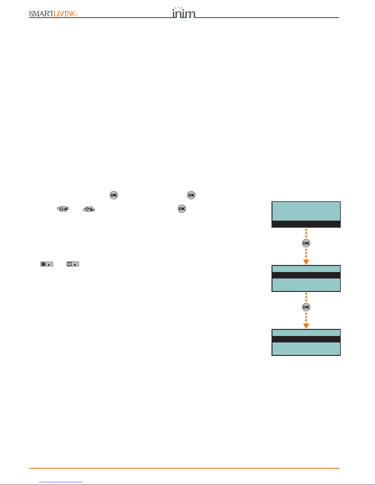
70 Options and programming methods
Anti-intrusion control panels
7-8
Outputs
This programming section describes the programming processes of all the output
parameters.
SmartLiving control panels always provide 3 outputs:
•Relay output
• Open collector output (O.C.) 1
• Open collector output (O.C.) 2
The outputs configured on the Flex5/P and Flex5/U expansion boards are open-collector
outputs, with the exception the one configured on terminal T5 that can be configured as
an analogue output (industrial standard 0-10V).
The 5 outputs on the Flex5/DAC expansion board can be configured as:
• high-power relay output
• Triac ON/OFF output (default setting)
• Triac dimmer output
The terminal pairs of the Flex5/DAC OUT1-OUT2 and OUT3-OUT4 are provided with the
interlock function which is required in applications with, for example, rollerblind motors.
The interlock function inhibits the contemporary activation of the associated terminals.
It is activatable through the respective option which must be enabled for both terminals
in the pair.
Via Keypad
1. Access the “Outputs” section.
Type-in Code
(Installer PIN)
, PROGRAMMING Outputs .
2. Use and to select the output thenpress .
Description
This is the editable output label (device description). At default all the outputs, except
for the 3 outputs on the control panel motherboard, assume the description of the
peripheral they refer to followed by the respective terminal.
Follow the instructions in paragraph 7-7 Zones - Descriptions.
Options
Use and to enable or disable the selected option.
• Norm. closed: this will be the output status during standby.
• Monostable
• Buzzer (beeper): generates a 1Khz signal when the output activates - can be used
to drive a buzzer.
• Blinker: generates an intermittent signal (0.5 sec ON and 0.5 sec OFF) when the
output activates. It can be employed in direct control of a visual signalling device
(e.g. flasher).
• ON afterRestoral: the output does not restore-to-standby (reset) when the
trigger-event clears. This option is useful in situations that require a trigger event for
output activation and a reset event for its deactivation.
This option applies to “Bistable” outputs only. If it is enabled for a bistable output
with reset-event configuration, it will deactivate the output instead of activating it
(refer to paragraph 7-11 Events).
This option is useful in situations that require the output to reveal event “memory”
(event signalling which continues even after the event has cleared). In this case, the
output is deactivated by a different event which restores it directly to standby
(resets the output).
For example:
•• O.C. Output 1 is configured as "ON afterRestoral"
•• the activation of “Mains failure” event is programmed to trigger O.C. Output 1
•• the restoral (reset) of "Valid code"event is programmed to trigger O.C. Output 1
In the event of Mains failure, O.C. Output 1 will activate but will not restore to
standby (reset) when the Mains failure condition clears. It will restore to standby
(reset) only when “CODE 1” is entered a keypad and generates a “Valid code” for the
“CODE 1” event.
• Switching - each time you execute an “activate output” command, the output will
switch status. Therefore, if it is deactivated it will activate and vice versa.
However, each time you execute a “deactivate output” command, the output will
always deactivate.
If you wish to manage this feature through a shortcut, you must use the “Activate
outputs” shortcut.
RELAY 001
Description
Options
Monostable time
PROGRAMMING
Terminals
Zones
Outputs
Outputs
RELAY 001
OUTPUT 001
OUTPUT 002

Installation and programming manual
Options and programming methods 71
• Dimmer - the output is a dimmer output thus the power supplied through the
terminals can be adjusted by the end-user
• Relay Use - the output is a relay output
• Home automation - if the control panel enters programming mode, the activated
output will not return to stand-by status.
• Interlocked This option enables the interlock function on the pair of terminals
which the terminal of the selected Flex5/DAC belongs to (pairs OUT1-OUT2 and
OUT3-OUT4).
In order for this to be valid, this option must be enabled for both terminals in the
pair.
Note
If the stand-by status of the output is determined by the occurrence of an event, the output will
still not return to stand-by status during programming mode.
Note
A declaration as to the type of output which is incoherent with the output itself may cause
malfunction.
Monostable time
This parameter applies to “Monostable” outputs only. This interval can be expressed in
seconds or minutes (see “info” box).
When a “Monostable” output receives an activation signal, it will remain active (On) for
the programmed time, regardless of the status of the trigger-event. In some cases,
“Monostable” outputs can be forced to standby before the programmed monostable
time runs out.
Use keys and and the number keys to set the times.
Via PC
Programming zones via the SmartLeague application is accomplished by the selection
and programming of the terminal configured as output, described in paragraph 7-6
Terminals.
7-9
Walk test
This section provides a quick and easy way of testing all the configured inputs.
After initializing the Walk test, all you need to do is walk through the protected
partitions and then check the detection capacity of the inputs via the system
keypad or SmartLeague software application.
Via Keypad
Type-in the code
(Installer)
, PROGRAMMING Walk test .
On access this section, the full list of configured zones appears on the screen.
As these input zones are violated by the operator carrying out the walk test,
they will be cleared from the list and the keypad will emit a long beep.
You can consider the outcome of test positive when there are no zones left on
the list.
Via PC
Select “Check control panel - Monitoring - Walk test” option from the menu bar.
The display will show a list of all the configured zones and the start test button.
Once you press the test button, the violated zones will be marked by a red dot.
If this value is
expressed in
minutes, there is
an error margin of
1 minute (for example, if
you set 5 minutes, the
period can vary between 4
and 5 minutes).
PROGRAMMING
Zones
Outputs
Walk test
Walk test
Panel T01
Panel T02
Panel T03

72 Options and programming methods
Anti-intrusion control panels
7-10
Telephone
This programming section deals with all the telephone parameters.
The built-in ATS device (alarm transmitting system) provides the following features (in
compliance with EN50131 relating to the notification of information).
• Type B notification apparatus (refer to EN50131-1:2008-02, paragraph 8.6
Notification, Table 10, page 46, Grade 2).
• The ATS2 notification apparatus specified in the table, is characterized by:
•• Transmission time - classification D2 (60 seconds)
•• Transmission time - max. values M2 (120 seconds)
•• Classification time - classification T2 (25 hours)
•• Substitution security - S0 (no detection of device substitution)
•• Information security - I0 (no detection of message substitution)
Via Keypad
Type-in Code
(Installer PIN)
, PROGRAMMING Telephone .
Select number
The Phonebook provides 15 number slots which can be selected by means of keys
and . You can program the following fields for each selected number:
• Number: edit field for the contact number (maximum 20 digits). Accepts also “,” (=
2 second pause), “*” and “#”.
• Description: edit field for the name of the contact person. Follow the instructions in
paragraph 7-7 Zones.
• Type:
•• None - the selected number can receive SMS text messages only
•• Voice - the selected number can receive voice calls and SMS text messages
If the number refers to the Alarm Receiving Centre, assigns the ARC protocol
(reporting format):
•• Ademco 10bps
•• Ademco 14bps
•• Franklin 20bps
•• Radionics 40bps
•• Scantronic 10bps
•• CONTACT-ID
•• SIA - Level 1 SIA is applied This reporting format (protocol) is capable of sending
descriptions of the objects in ASCII characters. if you do not wish to send the
descriptions in ASCII characters, select “No SIA strings” (refer to paragraph 7-5
Panel options). You can set a 4, 5 or 6 digit customer code for this protocol.
•• Ademco Express
•• CESA
•• SIA-IP
Use keys and to select the number type then press .
If a telephone number is “SIA-IP” type, the IP address and port of the SIA-IP receiver
must be entered in the receiver number field in the “Number” section, using the
following format:
xxxyyyzzzttt,ppppp
where:
- “xxxyyyzzzttt” are the 4 octets of the IP address (standard IPv4), each of which should
be written with 3 figures and, if necessary, “0” filler characters and no separation points.
- “ppppp” is the port and should be written with 5 figures and, if necessary, “0” filler
characters.
• Account code: a 4-character alphanumeric code which identifies the caller in
reports to the Alarm Receiving Centre. Some protocols (reporting formats) accept
digits only, whilst others accept also “A”, “B”, “C”, “D”, “E” and “F”, available using
keys .
• Partitions: this option allows you to associate each telephone number with specific
partitions. By selecting the partitions, using Keys and , you enable/disable
the users (who have at least one of these partitions in common with the telephone
number) to modify the number concerned.
PROGRAMMING
Outputs
Walk test
Telephone
Telephone
Select number
Number of rings
Max.num.attempts
Select number
NUMBER 001
NUMBER 002
NUMBER 003
NUMBER 001
Number
Description
Type

Installation and programming manual
Options and programming methods 73
• Options:
•• Receive SMS, this option allows the telephone number to receive an SMS
message from the Nexus GSM module, as well as all other event-related
communications.
•• BackupOnOtherCha , this option, in the event of call failure on a channel,
enables the control panel to carry out call attempts on an alternative channel,
and then retry on the original channel in order to alternate the set number of
attempts.
• Channel, this section allows you to select the channel for the priority routing of a
call in the event of incoherent programming or in the event of the failed accessibility
of the communication device:
•• PSTN
•• Nexus
•• SmartLAN
• Encryption - this section allows you to select the encryption type of SIA-IP
protocol:
•• None
•• AES 128 bit
•• AES 192 bit
•• AES 256 bit
Number of rings
This value determines the number of rings the system allows before picking up an
incoming call.
Max.num.attempts
This value determines the number of calls attempts the system will make before
deleting the contact number from the call queue.
Message repeats
This value determines the number of times the voice message will be played during the
call.
All the above-mentioned values can be programmed as follows:
1. Use keys and to select the field you wish to change, then use the number
keys ( , etc.) to edit the number.
or
Use keys and to increase or decrease the number.
2. Press to confirm and exit.
Via PC
7-11
Events
This programming section deals with all the event-generated output actions.
The control panel recognizes all of the events described in this paragraph and is capable
of generating pre-programmed actions for each event, both when the event occurs and
when it restores/ends.
The actions are:
• activation of outputs
• activation/deactivation of outputs
• event notification via telephone call
• send SMS text messages
• event storage
• management of voice messages
• management of the option of each event
• activation of event related shortcuts
Table 7-5:
Telephone - via SmartLeague software programme
Option Part of the system Template/section
Select number
SmartLiving System - Telephone
Programming
Number of rings
Parameters settings - Telephone line parameters
Max.num.attempts
Parameters settings - Telephone dialer parameters
Message repeats

74 Options and programming methods
Anti-intrusion control panels
Telephone notifications (calls) are queued and sent out in chronological order. However,
some events may need to be notified immediately (for example, use of a code under
duress), therefore, such events can be given priority by selecting the “Priority” option.
Event notification via e-mail requires the use of a SmartLAN/G board (refer to
paragraph 3-10-3 SmartLAN).
Event notification via predefined SMS messages requires the use of a Nexus (refer to
paragraph 7-29-3 Text for SMS messages).
Note
If a list of telephone calls is programmed for the notification of an event as well as SMS
messages, the SMS messages will be sent before the telephone calls.
The following table shows the events the control panel recognizes, the number of
events for each type, the trigger and restoral method of each event and the event
category (Pulse).
Table 7-6:
Event type
Name Occurs when... Restores when ... Number of events
Pulse
events
Control panel
models
Zone alarm
A zone generates an alarm A zone restores
One event for each
zone
no all
Terminal tamper
A terminal detects tamper (short-cir-
cuit or wire cutting)
A terminal restores
One event for each
terminal
no all
Partition alarm
A 24h zone which belongs to the parti-
tion generates an alarm, or a zone
which belongs to the partition generates
an alarm during Away mode.
All the zones belonging to the par-
tition restore (reset).
One event for each
partition
no all
StayPartit.alarm
A zone which belongs to a partition
armed in Stay or Instant mode, gener-
ates an alarm.
All the zones belonging to the par-
tition restore (reset).
One event for each
partition
no all
Partition tamper
A zone which belongs to the partition
detects tamper (short-circuit or wire
cutting).
All the zones belonging to the par-
tition restore (reset).
One event for each
partition
no all
Zone bypass
A zone is inhibited A zone is enabled (switched On)
One event for each
zone
no all
Real-time zone
The electrical status of a zone switches
from standby to alarm
The electrical status of a zone
switches from alarm to standby
One event for each
zone
no
all
The event is independent of the zone type and the armed/disarmed status of
the partitions.
all
Partit.not ready
A zone which belongs to the partition is
not in standby status.
All the zones belonging to the par-
tition are in standby status.
One event for each
partition
no all
Away arm request
A request is made to arm the interior
and perimeter zones of the partition
A request is made to disarm the
partition
One event for each
partition
Yes all
Overtime request
A request is made to arm the partition
in Stay mode (perimeter zones only) or
in Instant mode
A request is made to disarm the
partition
One event for each
partition
Yes all
Partit.awayArmed
The partition interior and perimeter
zones have been armed effectively
The partition will be disarmed
One event for each
partition
no all
Partit.StayArmed
armed
The partition has been armed effec-
tively in Stay or Instant mode
The partition will be disarmed
One event for each
partition
no all
Disarm partition
The partition will be disarmed The partition will be armed
One event for each
partition
no all
Partition reset
A request is made to reset the partition
One event for each
partition
Yes all
Exit time
The partition exit time starts running The partition exit time expires
One event for each
partition
no all
Entry time
The partition entry time is running The partition entry time expires
One event for each
partition
no all
Pre-arm time
The partition Pre-arm time is running The partition Pre-arm time expires
One event for each
partition
no all
Overtime request
A request for overtime relating to the
partition is made
One event for each
partition
Yes all
Chime
A chime zone belonging to the partition
is violated
One event for each
partition
Yes all
Forced arming
At the time of an arming command,
relating to one or more partitions, there
are open zones on the partition/parti-
tions involved, or there are other condi-
tions present which lower system
security, nonetheless, the user arms the
system.
One event for each
partition
Yes all

Installation and programming manual
Options and programming methods 75
Failed to arm
The “OpenZonesArmLock” option is
enabled at the time of a partition arming command and there is at least one
open zone on the partition/s involved.
or
when one or more of the conditions
described in “LossTamp.ongoing” is
present (refer to “FaultForNotReady”,
paragraph 7-27 Other parameters).
One event for each
partition
Yes all
Valid code
A user-code PIN entered at a keypad is
recognized as valid
One event for each
code
Yes all
Valid key
A key used at a reader is recognized as
valid on the reader
One event for each
key
Yes all
Valid Code AtKeyp.
A user-code PIN entered at a keypad is
recognized as valid on the keypad
One event for each
keypad
Yes all
ValidKeyAtReader
A key used at a reader is recognized as
valid on the reader
One event for each
reader
Yes all
Partition code
A user-code PIN entered at a keypad is
recognized as valid on the partition
One event for each
partition
Yes all
Partition key
A key used at a reader is recognized as
valid on the partition
One event for each
partition
Yes all
Failed call
All attempts to call a specific telephone
number have failed
One call to the phone number has
been successful
One event for each
contact telephone
number
no all
Timer activated
The timer is enabled (On) The timer is disabled (Off)
One event for each
timer
no all
Thermostat ON
The activation conditions set for the
keypad thermostat occur.
The deactivation conditions set for
the keypad thermostat occur.
One event for each
keypad
no all
Scenario ON
The status of all the partitions corre-
sponds exactly to the pre-set scenario.
The status of all least one of the
partitions does not correspond to
the pre-set scenario.
One event for each
scenario
no all
ProgrammableEvt
See paragraph 7-11-3 Programmable events no all
Emergency key
One of the emergency-key duos is
pressed
One event for each
emergency-key duo
Yes all
Panic Ev.
The “Panic” shortcut has been acti-
vated.
15 Yes all
Periodic event
The Periodic Event occurs 4 Yes all
Panel opened
The control-panel enclosure is removed
The front of the control-panel is
replaced
1noall
Dislodged panel
The control-panel enclosure is detached
from the wall
The control-panel enclosure is
reattached to the wall
1noall
Zone fuse fault
The zone protection fuse on the control
panel is not operational (blown)
The zone protection fuse on the
control panel restores
1noall
IBUS fuse fault
The I-BUS protection fuse is not opera-
tional (blown)
The I-BUS protection fuse restores 1 no all
Low battery
The backup battery is low
(voltage below 10.4V)
The backup battery is charged
(voltage above 11.4V)
1noall
Mains failure
The primary power supply 230V~ fails
The primary power supply 230V~
is restored
1noall
Expansion tamper
An expansion board signals tamper con-
ditions
Tamper conditions clear on all the
system expansion boards
1noall
Keypad tamper
A keypad signals tamper conditions
Tamper conditions clear on all the
system keypads
1noall
Reader tamper
A reader signals tamper conditions
Tamper conditions clear on all the
system readers
1noall
Sound.flash.Tamp
A sounderflasher connected to the BUS
signals tamper
All the sounderflashers connected
to the BUS reset
1noall
Nexus tamper
The GSM dialer Nexus signals tamper
Tamper conditions clear on the
Nexus
1noall
Tamp. LIVPWR100
For future use
VideoSens.Tamper
For future use
Expansion loss
An expansion board cannot be found on
the BUS
All expansion boards can be found
on the BUS
1noall
Keypad loss
A keypad cannot be found on the BUS
All keypads can be found on the
BUS
1noall
Reader loss
A reader cannot be found on the BUS
All readers can be found on the
BUS
1noall
Table 7-6:
Event type
Name Occurs when... Restores when ... Number of events
Pulse
events
Control panel
models

76 Options and programming methods
Anti-intrusion control panels
Sound.flash.Loss
A sounderflasher cannot be found on
the BUS
All sounderflashers can be found
on the BUS
1noall
Nexus loss
The control panel is unable to communi-
cate the Nexus 100
Communication between the control panel and the Nexus restores
1noall
Nexus LIVPWR100
The control panel is unable to communi-
cate with the LIVPWR100 board
Communication between the con-
trol panel and the LIVPWR100
restores
1no
SmartLiving
G3
VideoSensor loss
For future use
Jamming
Wireless interference detected Wireless interference cleared 1 no all
Low battery WLS
The battery of a least one wireless
detector is running low
All the wireless detectors are run-
ning with sufficient power
1noall
WLS zone loss
Loss of at least one wireless detector
has been signaled (supervisory time-
out)
All the wireless detector are pres-
ent
1noall
Installer code
An Installer PIN entered at a keypad is
recognized as valid
1Yesall
Invalid code
An invalid code is entered at a keypad 1 Yes all
False key
An invalid key is used at a reader 1 Yes all
Nexus fault
The GSM dialer Nexus signals a fault
(see Chapter 9 - Errors and faults)
Fault conditions clear on the Nexus 1 no all
Tel. line down
The land line is not working The land line restores 1 no all
Hard reset
The control panel re-initializes. The system clock may be wrong or not working
properly.
1Yesall
Call queue full
There are no more slots left in the out-
going call queue
1Yesall
Successful call
The call is answered 1 Yes all
Programming
Access to system programming is
authorized
End of system programming 1 no all
Ongoing call
A call is sent A call ends 1 no all
SMSMessageFailed
Nexus failed to send SMS message 1 Yes all
Output fault
An output fails to switch status as com-
manded
1Yesall
Low credit
The credit remaining on the SIM card
inserted in the Nexus is below the mini-
mum credit threshold.
The remaining credit is above the
minimum credit threshold.
1noall
Time modified
There is a change in the date and time.
This event will be recorded together
with the date/time before the change.
There is a change in the date and
time.
This event will be recorded
together with the date/time after
the change.
1noall
Int. Resistance
The internal resistance of the battery
has exceeded the R
i max
value.
Refer to Table 2-2: Control panels -
electrical and mechanical features
The internal resistance of the bat-
tery returned to below the R
i max
value.
1noall
Battery shorted
A short-circuit condition has been
detected on the battery connection ter-
minals
The short-circuit condition is no
longer present
1no
SmartLiving
G3
Battery disconn.
The backup battery is disconnected The backup battery is connected 1 no
SmartLiving
G3
PwSupplyOverload
Output overload is detected on the
power-supply unit
Refer to Table 2-2: Control panels -
electrical and mechanical features
The electrical load returns below
the allowed limit
1no
SmartLiving
G3
PwSupply Overheat
The temperature of the power-supply
unit has exceeded the allowed limit
The temperature of the power-
supply unit is normal
1no
SmartLiving
G3
Ground fault
Leakage to ground is present
The leakage to ground condition is
no longer detected
1no
SmartLiving
G3
Overvoltage “x”
A voltage of over 14.5V has been
detected on terminal “
+AUX
” corre-
sponding to number “x” on the LIVP-
WR100 board.
The normal voltage on the termi-
nal has been restored.
1no
SmartLiving
G3
Overvolt. BUS
A voltage of over 14.5V has been
detected on I-BUS terminal “+” on the
LIVPWR100 board.
The normal voltage on the termi-
nal has been restored.
1no
SmartLiving
G3
Undervoltage
A voltage below 9.8V has been detected
on terminal “
+AUX
” corresponding to
number “x” on the LIVPWR100 board.
The normal voltage on the termi-
nal has been restored.
1no
SmartLiving
G3
Table 7-6:
Event type
Name Occurs when... Restores when ... Number of events
Pulse
events
Control panel
models

Installation and programming manual
Options and programming methods 77
Each event can be associated with 3 voice messages, selected from the message list
(refer to Appendix D, Voice messages).
• Message type
• Message A
• Message B
This feature allows you to create messages which will be played during event-related
voice calls to contact numbers, both at the start and end of the event.
The choice of messages and the number of times they are played depends on the
“AutomaticDialer” settings.
Via Keypad
1. Accessing the “Events” section
Type-in Code
(Installer PIN)
, PROGRAMMING Events .
2. Use keys and to select the event type (if you are dealing with a group
of events, repeat the required operation) and , then press .
3. Select:
• Activation, to programme the actions to be carried out when the event occurs.
• Restoral, to programme the actions to be carried out when the event ends.
4. Successively, the parameters to programme are:
TelephoneNumbers
Programme the call recipient numbers.
Message type
Message A
Message B
Select the number of the message (see Table 7-7: Event-related messages and
Appendix D, Voice messages):
1. Use keys and to select the field you wish to change, then use the number
keys ( , etc.) to edit the number.
or
Use keys and to increase or decrease the number.
Undervoltage BUS
A voltage below 9.8V has been detected
on I-BUS terminal “+” on the LIVP-
WR100 board.
The normal voltage on the termi-
nal has been restored.
1no
SmartLiving
G3
Short circuit “x”
A short-circuit has been detected on
terminal “
+AUX
” corresponding to
number “x” on the LIVPWR100 board.
The short-circuit is no longer pres-
ent.
1no
SmartLiving
G3
Short circuit BUS
A short-circuit has been detected on I-
BUS terminal “+” on the LIVPWR100
board.
The short-circuit is no longer pres-
ent.
1no
SmartLiving
G3
Overload “x”
A load of over 1.5A has been detected
on terminal “
+AUX
” corresponding to
number “x” on the LIVPWR100 board.
The terminal restores to normal. 1 no
SmartLiving
G3
Overload BUS
A load of over 3.5A has been detected
on I-BUS terminal “+” on the LIVP-
WR100 board.
The terminal restores to normal. 1 no
SmartLiving
G3
NoCommunPwSuppl
y
Communication between the power
supply unit and the control panel has
broken down.
Communication between the
power supply unit and the control
panel restores.
1no
SmartLiving
G3
Tel. on number 1
A call has been sent to phone number 1
The call has ended (even in the
event of negative outcome)
1noall
Tel.on number 15
A call has been sent to phone number 15The call has ended (even in the
event of negative outcome)
1noall
Sync.data IP2RX
The IP2RX synchronization process has
been carried out from a keypad (refer
to the User Manual, “Activations”)
1Yesall
IP conn. lost
The IP connectivity test is enabled and
the test result in negative (failed).
A connection attempt has been
successful.
1noall
IP conn. lost
Nexus/G has detected GPRS connectiv-
ity trouble.
The GPRS connectivity is restored. 1 no all
Table 7-6:
Event type
Name Occurs when... Restores when ... Number of events
Pulse
events
Control panel
models
Events
Activation
Restoral
Zone alarm
Panel T01
Panel T02
Panel T03
PROGRAMMING
Walk test
Telephone
Events
Events
Zone alarm
Terminal tamper
Partition alarm

78 Options and programming methods
Anti-intrusion control panels
2. Press to confirm and exit.
The following table shows the voice-message sequence in accordance with the
previously mentioned parameters and options.
Note
If an event is associated with the “Automatic dialer”, the “Type Message” option refers to
messages 261 to 312, that is to say, the messages containing the event descriptions (event
types).
Options
To be activated by keys and :
Class code
This is the CONTACT-ID reporting format Class-Code which corresponds to the event.
Table 7-7:
Event-related messages
“Automatic dialer”
enabled
“Automatic dialer”
disabled
Message type
Plays the message relating to the event type (e.g. “zone
alarm”, “Mains failure”)
This message should not be changed.
You can select any message from 1 to 219
Message A
Blank message, editable
Message B
Contains event details, for events which are not distinctive
(e.g. the “zone alarm” event indicates the zone concerned).
Event Activation
Sequence
1. Message type + 260
2. Message A
3. Message B
4. “Location” (244)
1. Message type
2. Message B
3. “Location” (244)
Sequence in the
event of Restoral
1. “Restoral” (97)
2. Message type
3. Message A
4. Message B
5. “Location” (244)
1. Message A
2. Message B
3. “Location” (244)
Table 7-8:
Event options
Option If enabled If disabled
Event ON to log
When the event occurs, it will be saved to the events log.
When the event occurs, it will not be saved to the events
log.
Event OFF to log
When the event clears, it will be saved to the events log.
When the event clears, it will not be saved to the events
log.
StartPeriodicEv.
When the event occurs, the system will generate Periodic
event number 1.
Silent event
If the event occurs, the system will generate silent calls
which will not be signaled on the keypads.
If the event occurs, the system will generate calls which
will be signaled on the keypads.
Clear call queue
When the event occurs, the system will cancel the outgo-
ing call queue.
Send address
In the case of voice calls, the system will include the
address of the location alarm (refer to the Table 7-7:
Event-related messages)
In the case of voice calls, the system will not include the
address of the location alarm (refer to the Table 7-7:
Event-related messages)
Local Message ON
When the event occurs, the system will play the event-
related voice message on keypad speaker n. 1
Local MessageOFF
When the event occurs, the system will not play the
event-related voice message on keypad speaker n. 1
Automatic Dialer
Refer to the Table 7-7: Event-related messages
Priority
Calls associated with this type of event have priority over
all other calls. Therefore, if a priority event occurs, any
ongoing calls will be interrupted and the priority-event
call will be sent immediately.
Note
This
option is
applicabl
e only
when a
Nexus
device is
installed
ForceAlt.Chann
el
All the programmed event calls will not be made over the
channel indicated by the “Channel” parameter when programming each phone number, but instead will be made
over the alternative channel (refer to paragraph 7-10
Telephone).
Automatic SMS
The dispatched SMS message will consist of the event
description in the Events log
The SMS text message can be selected from the 50 mes-
sages provided by the Nexus device. The SMS text mes-
sage is identified by the “SMS message number/index”,
as described below.
Enable SMS
When the event occurs, the control panel will send an
SMS message to all the duly enabled telephone numbers
(refer paragraph 7-10 Telephone)
When the event occurs, the control panel will not send an
SMS message

Installation and programming manual
Options and programming methods 79
Event code
This is the 2-character alphanumeric code, which corresponds to the event sent the alarm
receiving centre (ARC). For zone and terminal events (alarm, tamper, bypass), the “CCC”
field of the CONTACT-ID protocol counts the number of hard terminals in accordance with
the Hard terminals table (refer to Appendix E, Screw Terminals).
Outputs
When programming the Event-Activation section, you must programme the main output
which will be activated when the event occurs. When programming the Event-Restoral
section, you must programme the main output which will be activated when the event ends.
Select the output from the list (which includes the Relay outputs, OC1, OC2 and the
terminals configured as outputs and also the sounderflashers) and press .
Note
If the output has the “ON afterRestoral” option enabled (refer to paragraph 7-8 Outputs) and it is
programmed on event restoral, the output will deactivate when the event occurs.
For Zone alarm, Terminal tamper, Partition alarm, Stay partition alarm and Partition
tamper events, monostable outputs programmed in the “Outputs” section will restore
these events when, on expiry of the monostable time, the event concerned has
effectively returned to standby status. If the event status restores to standby while the
monostable time is running, the event itself will not be restored.
Other outputs
This section allows activation of added outputs (as well as the output programmed in
the “Outputs” parameter) when the event occurs or restores.
These added outputs can be selected by means of keys and from a
programmable list in the “Added Outputs” section.
OtherOutputsProg
This section allows the creation of the list of outputs (16 for “Activation” or 8 for
“Restoral” to be programmed in the “Other outputs” section.
Note
This is the sole list for the entire control panel and is independent of the type of event.
Use keys and to make your selection and then press to confirm.
SIA Codes
If the event is associated with calls using SIA or SIA-IP protocol, this option allows you to
programme the event code in accordance with SIA Standard, by selecting it from a list.
Use keys and to make your selection and then press to confirm.
An appendix provides an explicative table of all the SIA codes (Appendix G, SIA Codes).
Siren sound types
This section allows you to select the audible-visual signals emitted by the
sounderflashers, when these are programmed in the “Outputs” and “Other outputs”
section.
Please note that the “Tone Type” is a parameter of the event. Therefore, if several
sounderflashers have been programmed in relation to a specific event, they will all emit
the programmed tone when the event occurs. If a sounderflasher has been
programmed in relation to several events, it will emit the last tone type setting received
in order of time.
Use keys and to make your selection and then press to confirm.
For further information regarding the “Outputs”, “Other outputs” and “Tone type” parameters
of each event, refer to Appendix F, Combination of outputs triggered by events.
Via PC
Table 7-9:
Events - via SmartLeague
Option Part of the system Template/section
TelephoneNumbers
SmartLiving System - Events - select a single event
Programming
Message type
Message A
Message B
Options
Class code
Event code
Outputs
Other outputs
Parameters settings - Other outputs

80 Options and programming methods
Anti-intrusion control panels
SMS message number/index
This option can be programmed solely via the SmartLeague software programme.
This option is applies only when a Nexus device is installed and the “Automatic SMS”
option is disabled. It determines which of the 50 available SMS messages will be sent
(refer to paragraph 7-29-3 Text for SMS messages) when the event occurs.
7-11-1
Shortcut on event
A shortcut can be associated with each event, the selected shortcut will activate as soon
as the events activates. This process can be done via the SmartLeague software
program only.
These shortcuts function differently from those which can be activated by the user
(refer to Appendix B, Shortcuts at default) and allow the control panel to activate
automatically determined operations when the event occurs.
The programming phase can be accessed via the SmartLeague, by selecting the event
from the system tree menu (on the left) that is to be assigned to the shortcut on the
respective “Programming” page (on the right). The “Shortcut functions” section
provides check boxes that allow the selection of the shortcut and definition of the
relative parameter:
7-11-2
Output scenarios
The assignment of the activation shortcut of an output scenario to the activation and
deactivation trigger of each event can be done via the SmartLeague software program
only.
The SmartLiving control panel provides 50 output scenarios, each with a maximum of
10 outputs.
Programming occurs in two phases: the first is the definition of the scenarios, the
second is the assignment to the activation and restoral of the event.
SCENARIO DEFINITIONS
From the system tree menu on the left, select the “Events” option, the “Output
Scenarios” list will appear in the “Programming” section on the right.
There are 50 scenarios available in the list. Selecting one of them will allow you to use
the programming area, alongside the list, to configure each of the 10 outputs available.
OtherOutputsProg
SmartLiving System - Events Parameters settings - Outputs
SIA Codes
SmartLiving System - Events - select the event type
Programming - Digital Dialer
Siren sound types
SmartLiving System - Siren pattern
SMS message number/index
Parameters settings - Nexus
Table 7-9:
Events - via SmartLeague
Option Part of the system Template/section
Table 7-10:
Shortcut on event
Shortcuts Function Option
Activate scenario
Shortcut that activates the scenario selected in the check box along-
side.
One of the 30 shortcuts available
Activate output
Shortcut that activates the scenario selected in the check box along-
side.
One of the configured outputs
Deactivate output
Bypass zone
Shortcut that deactivates/activates the zone selected in the check box
alongside.
One of the configured zones
Unbypass zone
Disable code
Shortcut that deactivates/activates the code selected in the check box
alongside.
One of the available codes
Enable code
Disable key
Shortcut that deactivates/activates the key selected in the check box
alongside.
One of the available keys
Enable key
Activate thermostat
Shortcut that activates the keypad thermostat in the operating mode
selected in the check box alongside.
One of the keypads available
Thermostat operating mode
Deactivate thermostat
Shortcut that deactivates the keypad thermostat selected in the check
box alongside.
One of the keypads available
Dimmer up
Shortcut that increases/decreases the set value of the voltage supplied
to the dimmer output selected in the check box alongside.
One of the outputs configured as
dimmer
Dimmer down
Delete alarm memory
Shortcut that deactivates the outputs relative to zone/partition alarm
and tamper events and deletes the partition and system alarm and
tamper memories.
This shortcut operates on the partitions selected for the scenario.
One of the 30 shortcuts available

Installation and programming manual
Options and programming methods 81
For each of these it is necessary to indicate the output (from those configured) and the
activation type:
•
0/100
, percentage value for the dimmer outputs or analogue outputs of a Flex5 expansion.
•
ON
, command that activates the output or changes the activation status if the output is a
“switching” type output.
•
OFF
, command that deactivates the output
•
Force ON
, command that activates the output
•
Toggle
, command that changes the activation status of the output
SCENARIOS ON EVENTS
From the system tree menu on the left, select the event that is to be assigned to the
scenarios on the respective “Programming” page on the right.
The “Output scenarios” section provides two programming fields for the selection of the
scenarios, one relating to activation of the event and the other to its restoral.
7-11-3
Programmable events
A group of events is available for installer programming. Event activation and restoral
depend on a combination of other control panel events based on logical operations,
counters and timers.
On account of their enhanced flexibility, special attention is required during the
programming and testing phases of the programmable events. The effects of the
programmable events must always be rigorously tested.
Each programmable event consists of a structure of mathematical-logical operations,
counters and timers. The programming structure consists of:
• 10 programmable events for SmartLiving 505 and 515 control panels, 30 for
SmartLiving 1050 and 1050L and 50 for SmartLiving 10100L
• 40 timers
• 10 counters
Via PC
This programming process can be done only via the SmartLeague software programme.
Select a programmable event from “SmartLiving System - Programmable event” from
the tree menu on the left, then go to the “Programming” template on the right. The
key (next to the data transfer buttons) opens a window which will allow you the define
the event. This window is divided into two sections:
•Equation
• Timers and counter details
EQUATION
The logical expression of the event includes various parameters, which may have a
“real” value (either “1” or “active” - as in the case of a verified event) or a “false” value
(either “0” or “not active” - as in the case of a restored event):
Table 7-11:
Programmable event
A
Section for the compilation of the logical
expression.
B
Section for the definition of the timers and
counters.
C
Selection field and button for the inclusion of
the verified control-panel event to be included
in the equation.
The restoral of the event is included using the
event followed by the “NOT” operator.
D
Selection field and button for the inclusion of
the timer.
E
Selection field and button for the inclusion of
the counter.
F
Selection field and button for the inclusion of
the button.
G
Keys for the inclusion of the logical operators
in the expression.
H
Keys for the deletion of the entire expression
or the last element of the expression.
I
Field for the visualization of the expression.
J
Key for the commutation of the visualization
mode of the equation (parameters/descrip-
tions of parameters).
K
Field for the addition of eventual notes..
E
C
F
D
A B
J
K
I
H
G

82 Options and programming methods
Anti-intrusion control panels
TIMERS
A timer is a logical expression element (it may have an “active” or “non active” value).
It is characterized by an interval, therefore, you must specify an interval (in seconds)
for each timer you wish to include.
You can select up to four “Start events” (i.e. control panel events which trigger the
timer) and up to four “Reset events” (i.e. control panel events which interrupt the
timer). You can specify the “Edge” for each of the eight events, that is, the status
passage of the selected event (“Activation”, “Reset” or “Both”).
The last two options allow you to choose when the timer will be “active”:
• Timer active on Start event. The timer will become “active” on start, that is, when
a start event occurs, and will remain “active” for the sat time. The timer will become
“non active” when the set time expires or when a reset event occurs.
• Timer active with delay. The timer will remain “non active” on start, that is, when
a start event occurs and will remain “non active” for the specified time. The timer
will become “active” when the specified time expires.
Note
A timer with the “timer active with delay” option enabled will remain “active” until a reset event
makes it “non active” again.
COUNTERS
A counter is a logical expression element. It is characterized by an increasing value
(“Count”). The counter will have a “non active” value until it reaches the set value,
which will take the counter to the “active” value.
You can select up to four “Start events” (i.e. control panel events which increase the
counter value) and up to four “Reset events” (i.e. control panel events which annul the
counter). You can specify the “Edge” for each of the eight events, that is, the status
passage of the selected event (“Activation”, “Reset” or “Both”).
It is necessary to define an “Autoreset” time that will zero the count when, between two
successive increases, a superior time elapses. If you do not desire an “Autoreset” time,
you must set the time at “65535” (already set at default), in order to ensure that the
count never expires.
Note
You should not set an “Autoreset” value of less than 5 seconds.
Once the event programming process is complete and the event is sent to the control
panel, the event programming values will be checked for errors.
EXAMPLES
If you wish to generate an alarm (i.e. activate sounderflashers and dialer calls) when only two
PIRs (DET1 and DET2) go into alarm status within a pre-set time.
• T0000; timer 1 will activate when the “Zone alarm DET1” Start event activates for 30 seconds
• T0001; timer 2 will activate when the “Zone alarm DET2” Start event activates for 30 seconds
• Both conditions must occur together (AND)
T0000 AND T0001
• You must set the activation of the sounderflasher and dialer calls on a similarly-configured
programmable event.
• If the programmable event activates an on-BUS sounderflasher, associate its deactivation with an
event.
If you wish to activate an output for 40 seconds when key 17 is used to arm partition 1, and to
disarm and the same output when the partition disarms.
• T0000; associate timer 1 with the activation of the Start event of key 17 recognition
• T0000; timer 1 with a 40 second timeout, “timer active with delay” option enabled
• T0000; associate timer 1 with the restoral of the reset event of partition 1
• Programmable event 1 must be programmed as:
T0000
• Select the output you wish to activate in concurrence with the programmable event
• If the programmable event activates an on-BUS sounderflasher, associate its deactivation with an
event.
If you wish to receive a telephone call when a zone q, which belongs to partitions 1 and 2, is
violated and one of the two partitions is armed
The automation zone q always generates the zone alarm event (even when the partitions are
disarmed). However, the programmable event will occur only when the zone q is in alarm status
and at least one of the two partitions is armed.
• Configure zone q as “automation” belonging to partitions 1 and 2
• Remove all the outputs and phone calls associated with the “Alarm zone q” event
• The programmable event must be programmed as “Alarm zone q” AND (“Partition 1 armed in away
mode” OR “Partition 2 armed in away mode”):
E0010 AND ( E0790 OR E0791 )
• Associate the programmable event with the telephone call you wish to receive
If you wish to activate a telephone call after 3 consecutive wrong code entries (with a maximum
of 120 seconds between each entry).
• C0000; counter 1 will activate on activation of the “False code” Start event, with a count of 3, 120
second autoreset time
• The programmable event must be programmed as:
C0000
• Associate the programmable event with the telephone call you wish to receive

Installation and programming manual
Options and programming methods 83
If you wish to activate a telephone call and output when at least two detectors out of 5 go into
alarm status.
• The programmable event must be programmed as (“Alarm zone 1” + “Alarm zone 2” + “Alarm zone
3” + “Alarm zone 4” + “Alarm zone 5”)>=2
( E0000 + E0001 + E0002 + E0003 + E0004 ) >= V0002
• Associate the programmable event with the telephone call you wish to receive and the output you
wish to activate.
7-12
Timer
This programming section deals with the 10 system Timers.
Each timer can be programmed to manage:
• the partitions that codes and keypads belong to and have access to the
programming process of the timers via the user menu.
• two scheduled activation times (“ON”) for each day of the week.
• two scheduled deactivation times (“OFF”) for each day of the week.
The SmartLeague software program will allow you program up to 15 exceptions.
A timer can be associated with a:
• Partition - if a partition is associated with a timer which controls automatic-arming
operations (refer to paragraph 5-4 Activations in the User's Manual), it will arm
when the timer switches ON and disarm when the timer switches OFF.
• Code - if a code is associated with a timer, it will be enabled to operate the system
when the timer switches ON, and disabled when the timer switches OFF.
• Key - if a key is associated with a timer, it will be enabled to operate the system
when the timer switches ON, and disabled when the timer switches OFF.
In order to associate timers with any of the above-mentioned objects, it is necessary to
access the respective control-panel programming section.
Note
The timers must be enabled/disabled by the user (refer to paragraph 5-4 Activations in the User's
manual).
On exiting the programming session (via keypad, computer or modem) all the timers will be
enabled automatically. Therefore, if it will be necessary to disable the timers as required.
Via Keypad
1. Accessing the “Timers” section:
Type-in Code
(Installer PIN)
, PROGRAMMING Timers .
2. Use keys and to select the Timer thenpress .
Once the timer has been selected, it will be possible to activate the partitions for
access to programming or the activations for every day of the week:
3. Select the “Partitions” option and press .
4. Select the partitions with access and enable or disable them using and
.
5. Press to confirm and exit.
3. Use and to select the day of the week.
4. Select an activation or a restoral of the timer.
5. Set the selected time (expressed in hours and minutes) by means of keys and
then, using keys and select the number.
6. Press to confirm and exit.
Note
It is also possible to programme timer activation or restoral only.
If you do not wish to programme the timer activation or restoral setting, enter “--:--” in the field
you do not wish to program.
TIMER 001
PARTITION 001
PARTITION 002
PARTITION 002
TIMER 001
Partitions
Sunday
Monday
PROGRAMMING
Telephone
Events
Timers
Timers
TIMER 001
TIMER 002
TIMER 003
TIMER 001
PARTITION 001
PARTITION 002
PARTITION 002

84 Options and programming methods
Anti-intrusion control panels
Via PC
Select an item from “SmartLiving System - Timers” from the tree menu on the left, then
go to the “Parameters settings” template on the right:
The SmartLeague software programme allows you to set up 15 setting exceptions for
each timer. Each “timer exception” allows you to define different On and Off times for
the selected interval (1 or more days, 1 week, etc.). The pre-set times will be applied
for the entire interval. The system does not accept intervals which go over the end of
the year. Therefore, it is impossible to program an interval such as 12th December to
5th January. In such situations, you must program 2 “timer exceptions”, one from 12th
to 31st December and the other from the 1st to 5th January, both with the same On
and Off settings.
The exceptions have priority over the days of the week. For example, If a “timer
exception”, lets say 1st May, falls on a Tuesday the settings programmed for 1st May
will be applied.
Note
The exceptions cannot be programmed via keypad.
7-13
Partitions
This programming section deals with the system Partitions and the respective options
and parameters.
Via Keypad
1. Accessing the “Partitions” section:
Type-in Code
(Installer PIN)
, PROGRAMMING Partitions .
2. Use keys and to select the partition thenpress .
Description
This is the editable partition label (description).
Exit time
A period, expressed in minutes or seconds, during which the user must LEAVE the
partition after arming the system (see the “info” box). If you set “0” in this field, there
will be no Exit time (delay), therefore, any delayed zones, which belong to the partition,
will generate alarms if they are not in standby status when the system arms.
Entry time
A time (expressed in minutes or seconds) the system allows the user to disarm the
partition after violation of a delayed zone (for example, after opening the front door). If
the system is not disarmed within the set time it will generate an alarm (see “info”
box). If you set “0” in this field, there will be no Entry time (delay), therefore, any
delayed zones will generate alarms instantly if they are violated when the system is
armed.
Entry time 2
This is the second Entry time (delay).
Pre-arm time
This is the period (expressed in minutes) before an automatic arming operation (see
“info” box).
In order to comply with EN50131 instructions, the “Pre-arm” time must be set at a
value that is not “0”.
Patrol time
An “Inspection” period (expressed in minutes) which allows patrol-key/code holders
(security staff, night watchmen, etc.) to check the premises (see “info” box ).
All the above-mentioned “times” can be programmed as follows:
1. Use keys and to choose whether to indicate the time in seconds or
minutes (see note opposite).
2. Use keys and to select the field you wish to change, then use the number
keys ( , etc.) to edit the number.
or
Use keys and to increase or decrease the number.
3. Press to confirm and exit.
PARTITION 001
Description
Exit time
Entry time
PROGRAMMING
Events
Timers
Partitions
Partitions
PARTITION 001
PARTITION 002
PARTITION 003
If this value is
expressed in
minutes, there is an
error margin of 1
minute (for example, if you
set 5 minutes, the period can
vary between 4 and 5
minutes).

Installation and programming manual
Options and programming methods 85
Timers
Select the timer you wish to associate with the “auto-am” operations.
Note
Remember to enable auto-arm partition in the section:
User menu
,
Activations .
Forced auto-arm operations may occur, generated by events active at the time of the
auto-arm operation.
Options
• Auto-resetMemory - if enabled by means of the key, each partition arming
operation will reset the partition alarm/tamper memory automatically.
• Auto-arm STAYmode - if enabled by means of the key, the partition will arm
in Stay mode at the pre-set auto-arm time. If disabled by means of the key,
the partition will arm in Away mode at the pre-set auto-arm time.
• StopTelOn Disarm - if enabled, the call queue will clear when the partition disarms.
Via PC
Select an item from “SmartLiving System - Partitions” from the tree menu on the left,
then go to the “Parameters settings” template on the right.
7-14
User Codes
This programming section deals with the user code options/parameters.
The user code PINs must comprise 4, 5 or 6 digits. The PIN of user code n. 1 is “0001”
at default. The PINs of the successive user codes are “0002”, “0003”, etc.
Via Keypad
1. Accessing the" Codes” section:
Type-in Code
(Installer PIN)
, PROGRAMMING Codes .
2. Use and to select the code then press .
Description
This is an editable programming field for the code user's name.
Partitions
Select the partitions the user code is assigned to. Press , to enable the partition
and to disable it.
Options
Use and to enable/disable the code options.
• Partition filter - if this option is enabled, the code will be able to change the
parameters only of codes with a lower rank in the system hierarchy whose partitions
are amongst the partitions assigned to the code being programmed.
For example, if a code is configured as “Master” with “Partition filter” and is assigned
to partitions 1, 3, 5 and 7, it will be able to enable/disable or change the PIN of a
“User” code assigned to partitions 1 and 5 but not the PIN of a “User” code assigned
to partitions 1, 2, and 3.
• Text menu and User menu - the combination of these two options allows
immediate visualization of the menu screens on the keypad displays after
acceptance of a valid user PIN. Refer to the following table.
Table 7-12:
Combinations “text menu” and “user menu”
Case Text menu User menu Description
A
Disabled Enabled
Accesses the user-menu (shown as a list of operations the user
is enabled to perform); at this point the user can scroll the list
using and and select the required option.
B
Disabled Disabled
Visualization of the user-icons associated with function keys
, ..., ; at this point the user can press the required
function key and activate the associated shortcut.
C
Enabled Disabled
Shows the descriptions of the personalized user-icons associ-
ated with function keys. The descriptions of the shortcuts are
shown in place of their associated icons. The user can use
and to scroll the list of shortcut descriptions and
select the desired shortcut, which can be activated by means
of the key.
D
Enabled Enabled The same as “C”
PROGRAMMING
Timers
Partitions
Codes
Codes
CODE 001
CODE 002
CODE 003
User Code
User Code
Manage alarms
Arm/Disarm op.
Voice functions
User Code
Stop alarms
Delete memory
Nexus status
(A)
(B)
(C)

86 Options and programming methods
Anti-intrusion control panels
Note
In all methods of access (A, B and C), the key allows you to access/view the other cases in
succession, see figure.
• AnnounceShortcut - if enabled on a voice capable keypad, the descriptions of all
the shortcuts assigned to the code and associated with the number keys will be
announced after acceptance of the entered PIN.
• Remote access - if enabled, the code PIN can be used to operate the system from
any remote telephone.
If the code PIN is entered on a remote telephone keypad, only the shortcuts associated
with keys 0 to 9 can be used to:
•• Arm/Disarm
•• Stop alarms
•• Clear call queue
•• Delete memory
•• Activate Output
•• Deactiv. Output
•• Listen-in
•• Arming status
Any other type of command will have no effect.
•
Patrol
- if enabled, the code will be able to disable the system for the pre-set “Patrol time”.
•
Fixed length
- if enabled, after typing in a PIN and without pressing the key, the user
will be able to activate the shortcut associated with function key “F12”, programmed via the
“F1/4KeyShortcuts”, described later.
If this shortcut is number 1 (“Arm/disarm”) and all the partitions assigned to the user code
in question are disarmed, the command will arm them, otherwise it will disarm them.
A user code with this option enabled has access to its own menu only after pressing the
key and PIN entry.
F1/4KeyShortcuts
This section allows you to programme up to 12 shortcuts associated with keys , ...,
. After valid PIN entry, the keypad will show the icons that correspond to keys
, ..., and which are associated with these shortcuts. Press the corresponding
key to activate the respective shortcut.
0/9 Key shortcuts
This section allows you to program up to 10 shortcuts associated withkeys , ...,
. After PIN acceptance, the code user can activate the shortcut by pressing the
respective number key.
To assign the shortcuts to the function keys, work through the following steps.
1. Use keys and to select the key you wish to associate with the shortcut
then press .
2. Press then, using keys and , select from the “Type” list the shortcut
you wish to associate with the function key.
3. Press to confirm and exit.
4. If the shortcut is associated with “Arm/Disarm” operations, the application will
ask you to select a scenario. If the associated shortcut is “Activate output” or
“Deactiv. output”, the application will ask you to select the output.
Assigned outputs
This section allows you to enable/disable the outputs the code user can control
manually via the:
User
menu, Outputs ON/OFF .
1. Use keys and to select the desired output.
2. Use keys and to enable/disable manual control of the output for the
code concerned.
3. Press to confirm and exit.
It is possible to program a certain number of outputs which can be activated or
deactivated via keypad without entering a user code. For further details refer to
paragraph 7-28 Activating outputs without authentication.
Timers
This section allows you to assign a timer to the code. The code will be operative only at
the pre-set times.

Installation and programming manual
Options and programming methods 87
Type
This section allows you to assign a level (rank) in the system hierarchy to the selected
code (refer to paragraph 1-6-2 User).
Note
The default level of code number 1 is “Master”; the default level of all the other codes is “User”.
Enable/disable
This section allows you to enable/disable access to the various sections of the User
Menu.
For further details regarding the sections of the User Menu, refer to the User Manual.
The programming steps are identical to those of “Outputs ON/OFF”.
Via PC
Select an item from “SmartLiving System - Users - Codes” from the tree menu on the
left, then go to the “Parameters settings” template on the right.
7-15
Installer codes
This section allows you to program the functions of the 2 installer codes. The user code
PINs must comprise 4, 5 or 6 digits.
Via Keypad
Type-in a valid code
(Installer)
, PROGRAMMING Installer code .
ChangeInst. PIN 1
For security reasons, you must change the PIN of the primary installer code (type-in
twice). The PIN is “9999” at default.
ChangeInst. PIN 2
For security reasons, you must change the PIN of the secondary installer code (type-in
twice). The PIN is “9998” at default.
Inst.code 2
Use keys and to enable/disable the sections of the installer menu the
secondary installer code can access.
Note
In this section, the secondary installer code can access Inst.CodePIN2 section only.
7-16
Keys
This section will allow you to programme the parameters of the digital keys and Air2KF100 wireless keyfobs (for details regarding the wireless keyfobs, refer to the Air2BS200 Transceiver Installation guide).
Via Keypad
Type-in Code
(Installer PIN)
, PROGRAMMING Keys .
Enroll
Each digital key and wireless keyfob must be enrolled separately on the system in order
to allow it to operate. The enrolling procedure is as follows.
1. View the readers in the control panel configuration. Select the reader you wish to
use for the enrollment of the key/s, then press . If you select a reader simulated by the Air2-BS200, a “W” will be shown at the end of the description.
2. Select the digital key you wish to enroll and press . If you are using an nBy/S
or nBy/X reader, all the LEDs will begin to blink to indicate that it is ready to
enroll the key.
3. The keypad will indicate the current description of the digital key concerned.
4. Hold the digital key in the vicinity of the reader and then move it away. For Air2KF100 wireless keyfobs, press simultaneously keys 3 and 4.
5. The keypad will emit a beep to confirm that the digital key has been successfully
enrolled. If you are using an nBy/S or nBy/X reader, the red LED will go On. The
digital key description will go to the next key automatically. This method (from
step 4.) allows you to enroll as many digital keys as the system requires.
PROGRAMMING
Partitions
Codes
Installer Code
Installer Code
ChangeInst. PIN
1
ChangeInst. PIN
Readers
READER 001
READER 002
READER 003
PROGRAMMING
Codes
Installer Code
Keys
Keys
Enroll
Key parameters
Delete key

88 Options and programming methods
Anti-intrusion control panels
6. Once you have completed the enrolling process, press or .
Note
All the enrolled keys will be enabled to operate the system immediately.
Key parameters
This section allows you to programme all the parameters of the selected digital key.
• Description - editable field for the name of the digital key user.
• Partitions - the partitions the digital key is assigned to and therefore can control.
• Options - activated by means of keys and , are:
• Timers - this section allows you to associate a timer with the digital key. The key
will be able to operate the system only when the associated timer is “On”.
• Shortcuts - this section allows you to programme up to 4 shortcuts (F1, F2, F3, F4)
for each key.
The shortcut associated with the key can be one of the following types:
•• None
•• Arm/disarm
•• Stop alarms
•• Clear Call Queue
•• Delete memory
•• Activate Output
•• Deactiv. outputs
•• Overtime
•• Teleservice req.
•• Voice guide
If a digital key is held in the vicinity of an nBy/S or nBy/X reader, the LEDs will run
through a series of visual signals with the following meanings:
Delete key
This section allows you to delete enrolled digital keys from the system configuration.
The enrolled digital keys can be found in the list with the symbol.
1. Use keys and to select the enrolled digital keys you wish to delete.
2. Press to delete the selected digital key.
3. Press to confirm and exit.
Table 7-13:
Key options
Option If enabled If disabled
Patrol
The digital key will be able to disarm specific parti-
tions for patrol purposes.
Maintenance
The digital key will be able to block alarm/tamper
outputs for the time that it is held in front of a
reader.
Use
keyShortcuts
If a digital key is held in the vicinity of a reader, only
the digital key shortcuts will be indicated, and not
the reader shortcuts.
If a digital key is held in the vicinity of a reader,
only the reader shortcuts will be indicated and, if
configured, the first shortcut programmed on the
digital key.
These options do
not apply to
Air2-KF100
wireless
keyfobs.
DisarmNotAllo
wed
If a digital key is held in the vicinity of a reader
when partitions are armed, the Disarm option will be
inhibited (all LEDs Off).
If a digital key is held in the vicinity of a reader
when partitions are armed, the Disarm option will
be allowed (all LEDs Off).
Table 7-14:
Readers - LED visualization
LED indicator sequence
Option: Use keyShortcuts
enabled disabled
1
Red LED On Digital key shortcut F1 shortcut associated with the red LED on the reader
2
Blue LED On Digital key shortcut F2 shortcut associated with the blue LED on the reader
3
Green LED On Digital key shortcut F3
shortcut associated with the green LED on the
reader
4
Yellow LED On Digital key shortcut F4
shortcut associated with the yellow LED on the
reader
5
All LEDs On This sequence does not occur Digital key shortcut F1
6
All LEDs Off
Option: DisarmNotAllowed
enabled disabled
No request to arm ALL the partitions common to
both the key and reader.
Request to arm ALL the partitions common to both
the key and reader.

Installation and programming manual
Options and programming methods 89
Enable/disable
This section allows you to enable/disable the digital keys:
1. Use keys and to select the digital key you wish to enable/disable.
2. Use keys and to enable/disable the selected digital key.
3. Press to confirm and exit.
Via PC
Select an item from “SmartLiving System - Users - Digital keys” from the tree menu on
the left, then go to the “Parameters settings” template on the right.
7-17
Arming scenarios
This section allows you to configure up to different 30 arming scenarios.
Via Keypad
1. Access “Arming scenarios” section.
Type-in Code
(Installer)
, PROGRAMMING Arming scenarios .
2. Use keys and to select the scenario thenpress .
Description
Editable field for the description of the scenario.
Icon
This section allows you to select the icon you wish to assign to the scenario, simply by
indicating the icon number (refer to Appendix B, Shortcuts at default):
1. Use keys and to scroll across the digits.
2. Use the number keys ( , etc.) to edit the number.
3. Press to confirm and exit.
The “Arm” shortcut associated with function key , ... , will visualize the icon
selected in this section.
Partitions
This section allows you to configure the scenarios of all the partitions managed by the
various models.
1. Use keys and to select the partition, then press .
2. Use keys
and to select the operating mode (Away, Stay, Disarm, etc.).
• None - the current operating mode of the partition will not be changed.
• Away - the partition will arm in Away mode (interior and perimeter).
• Stay - the partition will arm in Stay mode (perimeter only).
• Instant - the partition will arm in Instant mode (perimeter only with zero delay).
• Disarm - the partition will disarm.
Output
Each scenario, when applied, can activate one output (via keypad, at reader, over-the-
phone, etc.). Use and to select the output then press .
Note
It is possible to use a scenario to activate an output. This can be done through the Scenarios
section by simply leaving the respective “Partition” programming fields free (None), thus allowing
the association of the Icons with the outputs.
3. Press to confirm and exit.
Via PC
Select an item from “SmartLiving System - Scenarios” from the tree menu on the left, then go
to the “Parameters settings” template on the right.
SCENARIO 001
Description
Icon
Partitions
PROGRAMMING
Installer Code
Keys
Arming Scenarios
Arming Scenarios
SCENARIO 001
SCENARIO 002
SCENARIO 003

90 Options and programming methods
Anti-intrusion control panels
7-18
Shortcuts
This section allows you to setup all of the available shortcuts.
Via Keypad
1. Accessing the “Shortcuts” section:
Type-in Code
(Installer PIN)
, PROGRAMMING Shortcuts .
2. Use keys and to select the shortcut thenpress .
Description
This is the editable label which identifies the shortcut.
Icon
This section allows you to select the icon you wish to represent the scenario, simply by
indicating the icon number (refer to Appendix B, Shortcuts at default):
1. Use keys and to scroll across the digits of the number.
2. Use the number keys ( , etc.) to edit the number.
3. Press to confirm and exit.
Via PC
Select an item from “SmartLiving System - Shortcut icons” from the tree menu on the
left, then go to the “Parameters settings” template on the right.
7-19
Expansions
This section allows you to programme the parameters of the expansions.
Via Keypad
Type-in Code
(Installer PIN)
, PROGRAMMING Expansions .
Enable/disable
This section allows you to add/remove expansions from the I-BUS configuration, by
means of keys and .
ChoosePeripheral
This section allows you to select an expansion and program the descriptions and the
options:
• Description - editable field for the name of the expansion.
• Options - keys and allow you to enable activation of the expansion
buzzer on activation of terminal 1 configured as an output.
Via PC
PROGRAMMING
Keys
Arming Scenarios
Shortcuts
Shortcuts
Arm/Disarm
Stop alarms
Clear Call Queue
Table 7-15:
Expansions - via SmartLeague software programme
Option Part of the system Template/section
Enable/disable
/ Project
ChoosePeripheral
Expansions - select the expansion Programming
PROGRAMMING
Arming Scenarios
Shortcuts
Expansions
Expansions
Enable/disable
ChoosePeripheral

Installation and programming manual
Options and programming methods 91
7-20
Keypads
This section in the installer menu allows you to program the parameters of the keypads.
Not all the keypad parameters can be accessed via the installer menu. Depending on
the type of keypad or programming process, it may be necessary to use the
SmartLeague software program or, in the case of Alien keypads, access the appropriate
section of the keypad functions.
Via Keypad
Type-in Code
(Installer PIN)
, PROGRAMMING Keypads .
Enable/disable
This section allows you to add/remove expansions from the I-BUS configuration, by
means of keys and .
ChoosePeripheral
This section allows you to program the various options of the selected keypad.
• Wireless - This section allows you to start the enrolling process of the wireless
keypad (future use)
• Temp. hysteresis. - this parameter allows you to enter the hysteresis value for the
“Air conditioning” function on the selected keypad (if enabled).
The entered value must be expressed in °C decimals (from a minimum of 0 to a
maximum of 4).
• Description - editable field for the name of the digital key user.
• Partitions - use and to enable/disable the keypad on the system
partitions.
• Options:
•• Temperature off - if this option is enabled, the room temperature will be flashed
in alternation on the display. This option is valid for keypads with built-in
temperature sensors only.
••
SilentExitTime
- enables/disables the buzzer during partition Exit Time.
••
SilentEntryTime
- enables/disables the buzzer during partition Entry time
•• SignalExitTime - enables/disables the buzzer when terminal T1 on the keypad is
activated as an output.
•• Disable bell - enable/disable the buzzer that signals violation of the bell zone
relative to the keypad in question.
•• LED Off in standby - if enabled, this option switches of the relative LEDS after
at least 40 seconds of inactivity on the keypad.
•• NO Superv. WLS - If enabled, this option inhibits fault signalling in the event of
loss of wireless devices.
This option is co-related to the control panel parameter “Wireless Superv.” (refer
to paragraph 7-27 Other parameters).
•• Disable tamp. WLS - If this option is disabled, open/dislodgement tamper on
Air2 devices will not generate the respective events.
• F1/4KeyShortcuts - setting of the shortcuts assigned to keys , ..., .
If you are programming an Alien keypad, this shortcut refers to the position in the
list available in the “Scenarios” section of the Alien keypad you are working on.
Function keys F1 to F12 must be selected separately and programmed as follows:
•• Type - this is the shortcut action which can be selected from those available
(refer to Appendix B, Shortcuts at default). It is necessary to programme an
extra parameter for some shortcuts:
- “Arm/disarm”, this parameter refers to one of the 30 scenarios
- “Activate outputs”, this parameter refers to the output that will be deactivated
- “Deactiv. outputs”, this parameter refers to the output that will be deactivated
Note
The “Listen-in” and “Arming status” will have no effect if the respective command is entered at a
keypad.
If you are programming an Alien keypad, the only type of shortcut that functions is “Arm/disarm”.
•• Options - activated by means of keys and , are:
- Requires code - if enabled, the system will ask for user-code entry before
activating the shortcut. If the system recognizes the entered user code, it will
activate the shortcut command.
- SecurityRiskCode - if you enable this option, you must also enable the
“Requires code” option. When this option is enabled and the selected
shortcut involves a scenario that completely disarms a partition, or switches
a partition from Away mode to Stay mode, the security of your system will
obviously be at risk, therefore, the system will request code entry.
PROG. KEYPADS
KEYP. 001
KEYP. 002 W
KEYP. 003
Keypads
Enable/disable
ChoosePeripheral
PROGRAMMING
Shortcuts
Expansions
Keypads
Keypads
Enable/disable
ChoosePeripheral

92 Options and programming methods
Anti-intrusion control panels
- Confirm - if enabled, the system will ask the user for confirmation (press )
before activating the function-key shortcut. This method draws the users
attention to requested operations that do not require codes, and thus avoids
accidental arm/disarm operations, etc.
This option is not available for Alien keypads.
It is possible to program a certain number of outputs which can be activated or
deactivated via keypad without entering a user code. For further details refer to
paragraph 7-28 Activating outputs without authentication.
Via Alien keypad
Access the “Settings” section by tapping the button , type-in a valid user code in
order to access the “Alien” section.
The complete description of the parameters in this section can be found in paragraph
paragraph 2-3 Keypads in the user manual.
Via PC
The process of programming the graphic interface and maps on the Alien keypad must
be done through the SmartLeague software program.
Once you have selected the keypad from the system tree menu on the left, select
“Touch keypad” as type of keypad. The “General” section, which is the same for all
keypad types, appears with the following sections:
• “Alien graphics”, for the graphic interface setup (backgrounds, buttons, icons)
• “Alien maps”, for the configuration of the graphic maps accessed by means of the
key in the “Maps” section of the “APPs” .
In order to change the Alien parameter settings, your computer must be connected to
the USB port of the keypad.
For a complete description of the programming process of the Alien keypad, refer to the
SmartLeague software manual.
7-21
Readers
This section allows you to programme the reader options.
Via Keypad
Type-in Code
(Installer PIN)
, PROGRAMMING Readers .
Enable/disable
This section allows you to add/remove readers to the I-BUS configuration, by means of
keys and .
If it is a reader simulated by the Air2-BS200, a “W” will be shown at the end of the
description.
ChoosePeripheral
This section allows you to program the various options of the selected reader.
• Description - editable field for the name of the digital key user.
• Partitions - use or to enable/disable the reader on the system partitions.
• Shortcuts - this section allows you to programme the shortcuts associated with the
4 differently-coloured LEDs on the reader. In order:
•• Red LED shortcut
•• Blue LED shortcut
•• Green LED shortcut
•• Yellow LED shortcut
The shortcut associated with the LED can be one of the following types:
•• None
•• Arm/Disarm
•• Stop alarms
•• Clear call queue
•• Delete memory
Table 7-16:
Keypads - via SmartLeague software programme
Option Part of the system Template/section
Enable/disable
/ Project
ChoosePeripheral
Keypads - select the keypad Programming
CONTINUE?OK=YES
Enable/disable
READER 001
READER 002
READER 003
PROGRAMMING
Expansions
Keypads
Readers
Readers
Enable/disable
ChoosePeripheral
Prog. Address

Installation and programming manual
Options and programming methods 93
•• Activate Output
•• Deactiv. output
•• Overtime
•• Teleservice req.
•• View faults
Prog. Address
This section allows you to activate the address programming phase for nBy/S and nBy/X
readers.
Follow the instructions for addressing readers in paragraph 3-3-5 Addressing nBy readers.
Via PC
7-22
Sounders
This section allows you to programme the parameters of the sounderflashers connected
to the I-BUS and enroll wireless sounderflashes.
Wireless sounderflashers can be programmed via the SmartLeague software
programme only.
Via Keypad
Type-in Code
(Installer PIN)
, PROGRAMMING Sounders .
Enable/disable
This section allows you to add/remove sounderflashers from the I-BUS configuration, by
means of keys and .
ChoosePeripheral
This section allows you to programme the various options of the selected
sounderflasher.
•
Wireless
- this section allows you to start the enrolling process of the wireless
keypad.
• Description - editable field for the name of the sounderflasher.
Via PC
7-23
Language
Via Keypad
This option allows you to select the language the system uses in the User and Installer
menus for the descriptions of events, faults, etc. However, the edited descriptions of the
various system elements such as: zone, partitions, outputs, codes, descriptions will
remain unchanged.
Use keys and to select the desired language and to confirm.
Table 7-17:
Readers - via SmartLeague software programme
Option Part of the system Template/section
Enable/disable
/ Project
ChoosePeripheral
Proximity readers - select the reader Programming
Prog. Address
Proximity readers Programming
Table 7-18:
Sounderflashers - via SmartLeague software programme
Option Part of the system Template/section
Enable/disable
/ Project
ChoosePeripheral
Sounders - select the sounder/flasher Programming
PROGRAMMING
Keypads
Readers
Sounders
Sounders
Enable/disable
ChoosePeripheral
PROGRAMMING
Readers
Sounders
Language
Language
Italian
English

94 Options and programming methods
Anti-intrusion control panels
7-24
Messages
This section allows you to record (and playback) all the voice messages. The Table in
the Appendix shows all the pre-recorded messages provided by the SmartLogos30M
voice board.
Via Keypad
1. Accessing the “Messages” section:
Type-in Code
(Installer PIN)
, PROGRAMMING Messages .
2. Use keys and to select the field you wish to change, then use the number
keys ( , etc.) to edit the number.
or
Use keys and to increase or decrease the number.
3. Press .
4. Use keys and to select the instructions for the selected message
thenpress .
Record
Before recording a voice message, you must first select:
• No Message - no recording or playback
• High quality - for superior recording/playback quality
• Average quality - for good recording/playback quality (similar to phone-line
quality).
High quality messages occupy twice the memory space of average quality messages of
the same length.
The recording will start when is pressed, the running recording time (seconds) will
be indicated by a second-counter on the keypad display. If you wish to interrupt the
record/playback operation manually press , otherwise, it will end automatically when
the pre-set time-out expires.
Play
Message playback section. You can adjust the volume during the playback phase using
keys and .
Delete
Delete message section. The control panel will ask for confirmation before deleting the
message, by means of the key.
Via PC
The Parameters settings template of the “SmartLiving System - Voice messages” will allow
you to:
• upload all the voice messages
• download all the voice messages
• format voice board
Select an item from “SmartLiving System - Voice messages” from the tree menu on the
left, then go to the “Programming” template on the right and program the selected
message.
7-25
Default settings
This section allows you to reset to default settings all the control panel parameters,
auto-learn zone balancing values, auto-enroll I-BUS peripherals and restore the event
codes of CONTACT-ID reporting format.
Reset to factory default can be carried out at a keypad via the installer menu (details
follow), or via the control panel PCB, using the following procedure.
1. Disconnect all power to the control panel (mains 230V
~ and backup battery).
2. Short-circuit terminals “2” and “3” of the serial cable connector (refer to Table 2-
8: Mother board - description of parts, I).
3. Power-up the control panel and maintain the short-circuit condition on terminals
“2” and “3” for at least 5 seconds.
4. Restore the short-circuit condition.
Record
0034 sec.
CODING
Empty message
High quality
Average quality
Messages
Record
Play
Delete
PROGRAMMING
Sounders
Language
Messages
Messages
_01 Messages
(Min. 00)
(Min. 485)
Serial port
Terminals to
be short-
2
3

Installation and programming manual
Options and programming methods 95
Within 70 seconds the control panel will reset to default settings, re-enroll all the
peripherals currently on the I-BUS and, if a keypad is connected, will ask you to select
the Language.
Reset to factory default will not clear the events log.
Via Keypad
1. Access the “Default settings” section:
Type in Code
(Installer)
, PROGRAMMING Default settings .
2. Use keys and to select the function thenpress :
Factory data
If you select this option, the control panel will reset entirely to default settings.
ATTENTION!
This operations deletes all the previously programmed parameters.
Learn zone bal.
If you select this option, the control panel will learn (save to memory) automatically all
the balancing settings of all the zones (Patent Pending).
The zone-balancing options are:
• Normally Open
• Normally Closed
• Balancing (Single balancing)
• Double balancing
• Rollerblind with EOL
The balancing settings which are not acquired accurately are:
• Rollerblind without EOL (which is classified as a normally-closed generic zone)
• Double zone without EOL (which is classified as a normally-closed generic zone)
• Double zone with EOL (which is classified as a generic zone with Double balancing)
In order to allow accurate acquisition of the balancing settings of all the zones, you
must:
•• Wire and select the balancing settings of all the zones.
•• Ensure that all the zones are in standby status
•• Select the “Learn zone bal.” option.
•• Verify that the operation has been carried properly and that all the settings are
accurate (if any zones are not in standby status during this process their settings
will not be acquired accurately).
•• Set manually any inaccurate settings.
Autoenroll periph.
If you select this option, the control panel will enroll automatically all the peripherals it
finds on the I-BUS.
CONTACTIDDefault
If you select this option, the control panel will reset to default settings all the event
codes used for the CONTACT-ID protocol (refer to Appendix A, Technical terminology
and Glossary).
CONT-ID enumer.
If you select this option, the control panel (after confirmation) will implement
incremental numbering (from “1”) in the “CCC” field of the CONTACT-ID protocol (refer
to Appendix A, Technical terminology and Glossary) for the event relating to the zone.
SIA defaults
If you select this option, the control panel (after confirmation) will reset all the factory
default settings on SIA parameters of all events.
DeletePrg.events
Press the key to delete all the events saved to the control panel events log
(activation and restoral events):
• All outputs
• All calls
• All options
WLS data reset
Press the key to delete all the data relating to the Air2-BS200 device.
Note
The data relating to the wireless detectors and keyfobs will not reset on the control panel, nor will
the devices simulated by the Air2-BS200 transceiver be deleted from the configuration.
3. The control panel will ask for confirmation of this command (press ).
CONTINUE?OK=YES
PROGRAMMING
Language
Messages
Default settings
Default settings
Factory data
Learn zone bal.
AutoenrolPeriph.

96 Options and programming methods
Anti-intrusion control panels
Via PC
The SmartLeague software programme allows you to reset the control panel default
values only for the following parameters relative to the programming of events:
• digital dialer parameters
• “CCC” field of CONTACT-ID protocol of the zones
• phone calls on activation and restoral
• outputs on activation or restoral
• message playback on keypads on activation or restoral
• SIA protocol parameters
7-26
User functions
This section describes the functions the installer has in common with the user.
Via Keypad
1. Access the “User functions” section:
Type-in Code
(Installer)
, PROGRAMMING User functio ns .
2. Use keys and to select the function then press :
Activations
This section provides information regarding the “Cloud enrollment” option which allows
the SmartLiving panel to access INIM Electronics cloud service.
View
• Events log - allows you to view all the events saved to the log.
• Alarms log - allows you to view all the events relating to zone/partition alarm and
tamper saved to the log.
• Faults log - allows you to view all the fault events saved to the log.
• Arm/Disarm ops. - allows you to view all the arm/disarm operations saved to the
log.
Use key or to scroll the chronological events list. For some events, key
allows you to view the partitions details. For example, the details of an “Arm” command
will show the code and keypad concerned and, if you press , the list of partitions
involved.
• Nexus status - allows you to view (on the display) the following parameters of the
Nexus device:
1° line: GSM network provider (Vodafone, etc.), on the left side and BUS connections
on the right side of the string:
- if nothing appears, it means that the Nexus/G is connected to the BUS
- if the letter “G” appears, it means that the Nexus/G is connected to the BUS
and that the GPRS service is available
- if the letter “C” appears, it means that the Nexus/G is connected to the BUS
and that a teleservice request (TCP connection) or SIA-IP event report is being
sent
- if “
--
” appears, it means that the Nexus is connected to the BUS
2° line: GSM signal reception (value between 1 and 100)
3° line: balance, at the last operation (expressed in the local currency)
4° line: faults present - access the “View-Faults” section for details.
• System voltage - allows you to view the voltage the system uses.
• Zone status - allows you to view the status of all the zones. Use keys and
to scroll the list of accessible zones. The display shows the following zone
parameters:
1° line: zone description
2° line: zone status (“Standby”, “Alarm”, “Short”, “Tamper”), its activation status (“un-
bypassed” - capable of generating alarms, or “bypassed” - incapable of generating alarms)
Table 7-19:
Factory default settings - via SmartLeague software programme
Option Part of the system Template/section
CONTACTIDDefault
SmartLiving System - Events Programming - Maintenance events
CONT-ID enumer.
SmartLiving System - Terminals
Programming - “Rename the CCC in sequential
mode”
DeletePrg.events
SmartLiving System - Events Programming - Maintenance events
Installer Code
18:23 3/30/2017
KEYP. 001
VIEW
Events log
Alarms log
Faults log
PROGRAMMING
Messages
Default settings
User functions
User functions
View
Outputs ON/OFF
Set date/time

Installation and programming manual
Options and programming methods 97
3° line: various indications depending on the device type:
- wired zone; resistance value reading expressed Ohm
- wireless zone; wireless signal reception level
- level of smoke present in the smoke detection chamber of the Air2-FD100
smoke detector, expressed in mdB/m
4° line: level of contamination present in the smoke detection chamber of Air2-FD100
smoke detector (%)
Note
It is advisable to clean the detector when the value exceeds 90%.
• Faults - allows you to view any current faults.
• Panel version - allows you to view the firmware version and model of the
SmartLiving control panel.
Outputs ON/OFF
Allows manual activation/deactivation of the outputs by means of keys and .
Set date/time
Allows you to set the date and time of the control panel.
1. Use key or to select the programming field you wish to change (hour, minutes,
etc.).
2. Use keys and to change the selected field.
3. Press to save and exit.
Via PC
The SmartLeague software programme provides a section which, during a connection to
a SmartLiving control panel, allows you to monitor the entire system in real time and
access some of the above-mentioned parameters.
Select the Check control panel, Monitoring option from the menu bar.
A window containing various sections will open. The sections can be selected by means
of tags, each referring to a different part of the system.
7-27
Other parameters
This option allows you to programme the advanced functions of the control panel.
Via Keypad
1. Access the “Other parameters” section.
Type-in Code
(Installer PIN)
, PROGRAMMING Other parame ter s .
2. Use keys and to select the parameter thenpress :
Periodic Ev.
This options allows you to select one of the four periodic events and set the respective
parameters.
• Time per. Event - this parameter allows you to set the time (hh/mm), day, month
and year of the first “Periodic event” (refer to paragraph 7-11 Events).
Table 7-20:
User functions - via SmartLeague software programme
Option Part of the system
Section of the monitoring
window
Template/section
View/Log
SmartLiving System - Events log Programming
View/Nexus status
Peripheral details - Sounderflashers, isolators and Nexus
Nexus
View/System status
Remote keypad Control panel status
Power Power supply parameters
View/Zone status
Zones
View/Faults present
Remote keypad Control panel status
View/Control panel version
Window heading
Outputs ON/OFF
Zones Outputs ON/OFF
Set date/time
SmartLiving System SmartLiving System Programming

98 Options and programming methods
Anti-intrusion control panels
Note
The time/date setting of this parameter must be later than the control panel clock setting.
• PeriodicInterval - this parameter allows you to set the interval between each
“Periodic events” (expressed in hours).
To disable the “Periodic event”, set “0”.
• Options:
•• Per.Ev Continuous - if enabled, the system will generate the corresponding
periodic event regardless of its initial date/time. The event will be generated
when the programming session is exited, or when the system starts up, and will
be generated continuously when the set period expires.
•• PeriodicEv InMin - if enabled, the interval (period of time) between two
consecutive activations (“Period.Ev.Time”) will be established in minutes and not
hours.
Mains fail.Delay
This parameter allows you to programme the delay, expressed in minutes (see note ),
between mains failure and the “Mains failure” fault event signal.
LocKpadMessTimes
The number of times voice messages, relating to events recorded at the keypad, will be
played (only for keypads with voice functions).
The playback phase can be stopped by pressing any key. If you set a value of “255” the
playback can be stopped by pressing any key, this is the only method of stopping
playback.
OverThePhoneVol.
This is the volume of the voice messages over-the-phone.
Ring sensitivity
This value determines the reception sensitivity of incoming call rings. This option is
useful in situations of bad reception (break up) or noisy lines.
At default this value is set at 60. Accepted values: 1 to 120.
Wireless superv.
This value determines the wireless-device supervision time. Once the pre-set time
expires, the devices which do not respond will be signaled as lost. Accepted values: 12
to 250 minutes (30 minutes at default).
Tel. input gain
This value determines the volume of the incoming call signal. This option is useful in
situations which require better comprehension of DTMF tones and improvement of
teleservice intervention via modem.
Adj. temperature
This parameter will allow you to enter the effective value of the room temperature read
by an external thermometer. This value will replace the keypad temperature reading
and thus allow you to correct the temperature sensor on the keypad you are working on
(valid for keypads with temperature sensors only).
The entered value must be expressed in °C decimals (for example, type in 252 if the
temperature is 25.2 °C).
LowBattery delay
This parameter allows you to programme the delay, expressed in minutes, which will be
applied before “LowBattery” events will be signalled.
LinedownDelay
This parameter allows you to programme the delay, expressed in seconds or minutes,
which will be applied before “LineDown” events will be signalled.
All the above-mentioned parameters can be programmed as follows.
3. Use keys and to select the field you wish to change, then use the number
keys ( , etc.) to edit the number.
or
Use keys and to increase or decrease the number.
FaultForNotReady
This section allows you to select which events, other than zones in alarm status, will be
signaled as system security-risk conditions when the partition arms.
If this value is
expressed in
minutes, there is
an error margin of
1 minute (for example, if
you set 5 minutes, the
period can vary between 4
and 5 minutes).
OverThePhoneVol.
00_ Units
(Min. 010)
(Max. 100)
Tel. input gain
00_ Units
(Min. 001)
(Max. 120)
If this value is
expressed in
minutes, there is an
error margin of 4
minutes (for example, if you
set 7 minutes, the period can
vary between 3 and 7
minutes).

Installation and programming manual
Options and programming methods 99
Following are the events which can be enabled/disabled by means of keys and
:
•Zone fuse fault
• IBUS fuse fault
• Low battery
• Mains failure
• Tel. line down
•Jamming
• Low battery WLS
•WLS zone loss
• Nexus fault
•Detector dusty
•Zone faults
• Sounder faults
• Power faults
•Keypad faults
• LossTamp.ongoing
The last item groups the following events:
•• Panel opened
•• Dislodged panel
•• Expansion tamper
•• Keypad tamper
•• Reader tamper
•• Sound.flash.Tamp
•• Nexus tamper
•• Expansion loss
•• Keypad loss
•• Reader loss
•• Sound.flash.Loss
•• Nexus Nexus
•• Nexus LIVPWR100
• IP conn. lost
4. Press to confirm and exit.
Serial number
Section for the visualization of the Control panel serial number.
Via PC
7-27-1
Telephone line adjustment
The “OverThePhoneVol.” and “Tel. input gain” parameters can be used to correct the
voice functions of the dialer and the DTMF tones. The values of these parameters affect
each other, therefore, and a good result is always a compromise.
If you are not using a GSM interface, you should:
• Adjust one parameter at a time and carry out tests to verify the result.
• Increase/decrease the values in small steps (for example, from 25 to 22 and not
from 25 to 15).
• If the DTMF tones are not recognized, or are recognized with difficulty, decrease the value
of the “Volume Tel.voice” parameter (in small steps of 2 or 3 units) and verify the effect. If
there is no improvement, increase the value of the “VolumeTel. In.” parameter until an
acceptable level is achieved.
Periodic ev.
Time per. Event
PeriodicInterval
Options
PROGRAMMING
Default settings
User functions
Other parameters
Other parameters
Periodic Ev.
Mains fail.Delay
LocKpadMessTimes
Periodic ev.
Periodic ev. 001
Periodic ev. 002
Periodic ev. 003
Table 7-21:
Other parameters - via SmartLeague software programme
Option Part of the system Template/section
Periodic ev.
SmartLiving System
Parameters settings - periodic event
Mains fail.Delay
Parameters settings - I-BUS parameters
LocKpadMessTimes
Keypads Parameters settings - Keypad parameters
OverThePhoneVol.
SmartLiving System Parameters settings - Telephone options
Ring sensitivity
SmartLiving System - Telephone Parameters settings - Telephone line parameters
Wireless superv.
SmartLiving System
Parameters settings - Control panel parameters
Tel. input gain
Parameters settings - Telephone options
LowBattery delay
Parameters settings - I-BUS parameters
LinedownDelay
SmartLiving System - Telephone Parameters settings - Telephone dialer parameters
FaultForNotReady
SmartLiving System Programming - Forced arming faults

100 Options and programming methods
Anti-intrusion control panels
Do not increase the “VolumeTel. In” parameter excessively, as an excessive value
may cause incorrect interpretation of DTMF tones.
• If the volume of the telephone messages is low, increase the “Volume Tel.voice” (in
small steps of 1 or 2 units) and verify the effect. An excessive value of the “Volume
Tel.voice.” parameter may cause incorrect interpretation of DTMF tones.
In most cases, the value of the “Volume Tel.voice” parameter is between 15 and 25,
whereas, the value of the “VolumeTel. In.” parameter is between 20 and 30.
If there is a SmartLinkAdv GSM interface, it is possible to adjust the values of incoming
and of the output volume parameters of the SmartLinkAdv.
Note
Any changes to the value of the SmartLinkAdv incoming volume parameter come into effect
almost 2 minutes after the setting change, therefore, you must allow this time to pass before
verifying the effect.
7-28
Activating outputs without
authentication
It is possible to programme a certain number of outputs which can be viewed and
activated at the keypad without authentication (i.e. without entering a user code).
Access to these outputs depends on the type of keypad in use:
• for keypads with keys, you must activate the “Output control” shortcut (shortcut n.
21: ) associated with one of the , ...,
• for Alien keypads, you must access the “Commands” section by tapping the
button, then the “Domotics” section.
The outputs that can be activated from a keypad with the “NNN” address will be those
associated with a specific user code.
The keypad, code and relative outputs must be programmed in accordance with the
following procedure:
Via Keypad
1. Access the section of the Installer menu for the programming of the “NNN” keypad you wish to associate with the outputs:
Type-in Code (Installer) , PROGRAMMING Keypads ,
Select peripheral , Keypad “NNN”
2. Access the “F1/4KeyShortcuts” section and select a function key
3. Access the “Type” section and associate the selected function key with the “Output control” shortcut.
4. DO NOT ENABLE the “Requires code” option for the shortcut associated with the
function key undergoing programming.
5. Go back to the installer menu and access the “Codes” section.
6. Select the user code shown in the table in accordance with the control panel
model undergoing programming:
7. Access programming of the selected code, at the “Assigned outputs” section.
8. Use keys and to select the outputs from those available on the list.
Table 7-22:
User code number
Keypad number
SmartLiving Model
505, 515 1050 10100
001 026 041 086
002 027 042 087
003 028 043 088
004 029 044 089
005 030 045 090
006 / 046 091
007 / 047 092
008 / 048 093
009 / 049 094
010 / 050 095
011 / 096
012 / 097
013 / 098
014 / 099
015 / 100
Type
ZoneBypass menu
Voice memo
Output control
KEYP. NNN
Type
Options
KEYP. NNN
Partitions
Options
F1/4KeyShortcuts
F1/4KeyShortcuts
F1
F2
F3
 Loading...