

Page 1

SmartLink-P
PSTN dialler
Installation and
programming
manual
PATENT PENDING
Page 2

Installation and programming manual
Copyright
The information contained in this document is the sole property of
INIM Electronics s.r.l. No part may be copied without written
authorization from INIM Electronics s.r.l.
All rights reserved.
Directive 1999/5/CE (R&TTE) compliance.
Hereby INIM Electronics s.r.l. declares that SmartLink-P is in
compliance with the essential requirements and other relevant
provisions of Directive 1999/5/CE.
The full declarations of conformity of the above-mentioned devices
are available at URL: www.inim.biz/dc.html
2
.
Page 3

Installation and programming manual
Table of contents
Chapter 1 Introduction ...................................... 5
Chapter 2 General information ........................... 6
2.1 Manual details 6
2.2 Addressees 6
2.3 Software information 6
2.4 Intellectual property rights 6
2.5 Conventions 6
2.6 Manufacturer's name and address 7
2.7 Device identifier 8
2.8 Warranty 8
2.9 Safety laws 8
Chapter 3 Device management......................... 10
3.1 Transporting goods 10
3.2 Environmental conditions 10
3.3 Unpacking the device 10
Chapter 4 Technical description ........................ 12
4.1 Technical specifications 13
Chapter 5 Internal components ........................ 14
5.1 Terminal board 14
5.2 LED 15
Chapter 6 Device features ............................... 16
6.1 General features 16
6.2 Application 16
6.3 Intrusion control panel 16
6.4 Digital dialer (Contact ID) 17
6.5 Voice dialer 17
6.6 Remote control via DTMF 17
Chapter 7 Installation ..................................... 18
7.1 Installation instructions 18
7.2 Connections 19
Chapter 8 Settings.......................................... 21
8.1 Introduction 21
8.2 Installing the SmartLeague programming
software 21
8.3 SmartLeague software 22
8.4 Recommended programming flow 25
8.5 Set up referencing data 25
8.6 Setting up the SmartLink parameters 29
8.7 Programming the Inputs and Outputs —
IN&OUT 32
3
Page 4

Installation and programming manual
8.8 Programming the SmartLink-P as an intrusion control panel 36
8.9 Programming event generated actions 37
8.10 Programming periodic events 44
8.11 Remote control of SmartLink-P via DTMF
tones 45
Appendix A Wiring diagram of an intrusion-control pan-
el ...................................................47
Appendix B Default settings................................ 49
Appendix C Order codes.....................................50
Notes: ............................................51
4
Page 5

Installation and programming manual
Chapter 1
Introduction
The SmartLink-P is a landline-phone dialer (PSTN).
It is capable of sending alarm reports (Contact ID protocol) over the landline
to Alarm Receiving Centres and customized voice-messages to contact
numbers.
This device greatly enhances the security of control panels which are not
equipped with built-in dialers. It can also be used to provide reduced -size
installations with all main functions of an intrusion-alarm reporting appliance.
Introduction 5
Page 6

Installation and programming manual
General information
2.1 Manual details
Title: SmartLink-P Installation and Programming Manual
• Edition,Version: 1.00
• Month and Year of issue: December 2009
• Order code: DCMIINI0SLINKP
2.2 Addressees
•Installer
• Technical assistance
2.3 Software information
• SmartLeague software version: 3.x.x
• Firmware version: 2.x.x
Chapter 2
2.4 Intellectual property rights
The information contained in this document is private property. All rights
reserved.
No part of this document may be copied or reproduced unless expressly
authorized in writing by INIM Electronics s.r.l., in particular the parts
regarding the device specified in 2.7 Device identifier.
INIM Electronics s.r.l. shall not be responsible for any damage arising from
improper application or use.
2.5 Conventions
2.5.1 Glossary and terminology
Device; apparatus: refers to the device defined in 2.7 Device identifier.
Left, right, behind, above, below: indications using the operator's position
in front of the mounted device as the reference point.
Pulse output: same as "monostable output"
Dialer (phone, digital): same as "communicator"
Qualified personnel
of the respective laws and bylaws regarding service conditions and the
6 General information
: those persons whose training, expertise and knowledge
Page 7

Installation and programming manual
prevention of accidents, are able to identify and avoid all possible situations of
danger.
2.5.2 Graphic conventions
Text in italics: indicates the title of a chapter, section, paragraph, table or figure
in this manual or other published reference.
[Uppercase letters] (e.g.[A]): indicate the device parts
Note:
Attention:
Danger:
The detached notes contain important information about the
respective text.
The attention prompts indicate that total or partial
disregard of the procedure could damage the connected
devices.
The danger warnings indicate that total or partial
disregard of the procedure could injure the operator or
persons in the vicinity.
2.6 Manufacturer's name and address
INIM Electronics s.r.l.
Via Fosso Antico, Centobuchi
63033 Monteprandone (AP) - Italy
Tel: +39 0735 70 50 07
Tel: +39 0735 70 49 12
info@inim.biz - www.inim.biz
General information 7
Page 8

2.7 Device identifier
Alimentazione / Power
LBDTIN4ASLINKP
I
-P
12/2009
Tension / Alimentacion
Consumo / Consumption
Consommation / Consumo
70 mA
13.8 V
Classe di Isolamento /
Insulation class
Insulation class / Clase aislante
MADE
IN
ITALY
Figure 1 - Overview
Product class: PSTN dialer
Model: SmartLink-P
Year of manufacture: 2009
Installation and programming manual
2.8 Warranty
The manufacturer warrants the original purchaser that for a period of 24
months from the date of commissioning, the product shall be free of defects
in materials and workmanship. The warranty does not cover:
• Improper use or negligence
• Damage caused by fire, flood, wind, or lightning
•Vandalism
• Fair wear and tear
INIM Electronics s.r.l. shall, at its option, repair or replace any defective
products. Improper use, that is, use for purposes other than those mentioned
in this manual will void the warranty. For the full details and conditions
regarding the warranty, refer to the purchase order.
2.9 Safety laws
The aim of the instructions in this section is to ensure that the device is
installed and handled properly. This chapter contains vital information. The
installer should be familiar with this section and bring each item to the
attention of the system users.
8 General information
Page 9

Installation and programming manual
2.9.1 Managing electronic devices
The normal motions of any person may generate electrostatic potential of
thousands of volts. Discharge of this current through semiconductor devices
during handling may cause serious damage which although may not be
immediately evident may reduce the reliability of the circuits.
If located in their housings, the electronic circuits of INIM Electronics s.r.l.
products are highly immune to electrostatic discharge.
Do not expose the circuits to damage by removing the modules unnecessarily
from their housings.
1. When removing or handling the boards, hold the board edges only.
2. Do not touch the electronic components, the printed circuits or the metal
parts of the connectors.
3. Do not hand the module to another person without first ensuring that
you both have the same electrostatic potential. This can be obtained by
simply shaking hands.
4. Place the module on an anti-static surface or a conductor surface with
the same potential.
Further information regarding safe working procedures with electronic
appliances can be found under: IEC 61340-5-1 ed IEC/TR 61340-5-2.
2.9.2 Setting up the system
In order to provide adequate protection and instructions for proper use,
security professionals (Installers and maintenance/test technicians) must be
familiar with the operating procedure of this device.
Please read the instructions carefully before installing and/or servicing the
system.
Before first power-up, be sure that the earth connection has been completed
properly on the respective terminal.
The recommended minimum wire cross section for the earth connection is
2.5 mm
2
, that is, unless expressly stated in the additional documentation.
2.9.3 Replacement and disposal of used devices
Replacement
When replacing used devices, disconnect the devices concerned then
complete the connections of the replacement devices in compliance with the
instructions printed on the respective inserts.
Contact your local municipal offices for information regarding the disposal of
used electronic devices.
Disposal
Do not burn used electronic devices, or allow them to pollute the
environment (countryside, rivers, etc.). Electronic devices must be disposed
of in a safe environment-friendly way. In order to avoid short-circuits, take
all the necessary precautions when removing used batteries. Contact your
local municipal offices for information regarding the disposal of batteries.
General information 9
Page 10

Installation and programming manual
Chapter 3
Device management
3.1 Transporting goods
The individual devices are properly packed in cardboard boxes and
transported in extra-strong cartons. However, during storage and handling,
special care must be taken to avoid accidental damage (knocks and falls) and
to protect the boxed device from extreme heat and/or cold.
3.2 Environmental conditions
Temperature limits
-10° / +55°C for transport and storage
+5° / +40°C operating temperature
3.3 Unpacking the device
The goods must be unpacked with care. All waste packaging materials must
be disposed of in compliance with the local laws and bylaws in force.
The device is packed in a cardboard box.
Note:
Inside the box:
• SmartLink-P PCB mounted on one metal and three plastic supports
• The meta box contains:
- 10 resistors @ 15kohm
- 4 frontplate screws
The following accessory items must be ordered separately (see Appendix C
for the order codes):
• SmartLogos60 voice board
• Switching power supply/battery charger (13.8V 1A IPS12015DT)
10 Device management
The 1.2 A/h battery is not included. Ensure you have the
battery on hand before starting.
Page 11

Installation and programming manual
Figure 2 - SmartLogos60 and Switching power supply/battery
charger (IPS12015DT)
Device management 11
Page 12

Technical description
C
E
A
G
D
F
H
H
N
M
I
I
I
I
L
L
L
L
FSLINK 2.01
01/12/2009
QC Passed
Installation and programming manual
Chapter 4
Figure 3 - SmartLink-P: motherboard and backplate
Description of parts
[A] Terminal board
[B] LED indicators
[C] RS232 serial port connector
[D] Buzzer
[E] Battery connectors
[F] Firmware version label
[G] Tamper microswitch
[H] SmartLogos 60 voice board connector
[I] Wall-mount screw locations
[L] Frontplate screw locations
[M] Cable entry
[N] Battery housing
12 Technical description
Page 13

Installation and programming manual
Note:
INIM s.r.l. reserves the right to change, replace, in part or
entirely, the components not strictly relating to the user and
therefore, do not involve the installation process described in
Chapter 7 - Installation.
4.1 Technical specifications
Power supply 13.8Vdc ±10%
PCB operating current draw 40 mA in standby, 70 mA maximum
Maximum current draw on
terminal +AUX
Maximum battery-charge
current
Battery specifications 12V, 1.2Ah
Outputs Maximum 5
Inputs Maximum 5, with 3 programmable
Dimensions (W x H x D) 134 x 220 x 53 mm
400mA
400mA
open-collector outputs @ 150 mA
thresholds
Weight (without battery) 850g
Technical description 13
Page 14

Installation and programming manual
Chapter 5
Internal components
5.1 Terminal board
Figure 4 - Terminal board
Nr. Identifier Description Note
1 +PWR Positive
2-PWR Negative
3 +AUX Ancillary power 12Vdc
4Ground:
reference for signals on terminals;
Negative power
5 IO1 Input/Output terminals 13.8Vdc
6IO2
7IO3
8IO4
9IO5
10 OPEN Tamper protection Refers to the tamper-
11
12 To be connected to the mains earth.
microswitch contact (
‘[G]’)
.
table on page 12,
400mA
150mA
current
draw for
each
terminal
13.8Vdc
100mA
13
14
15 PSTN Land line (PSTN) connection
16
14 Internal components
To be connected to devices which access
the telephone line (e.g. telephones,
alarms, control panels, etc.).
Page 15

Installation and programming manual
2
3
1
Attention:
Note:
The device that supplies power to terminals 1 and 2
must be overvoltage and short-circuit protected.
A custom power supply to terminals 1 and 2 is available on
request. Order code: INIM IPS12015DT. Devices with same
electrical specifications can also be used.
5.2 LED
The SmartLink-P board provides three status LEDs, with the following
meanings.
Figure 5 - LED
LED Colour ON Blinking OFF
1GreenSmartLink-P
operating
2 Red PSTN line trouble PSTN line
3Yellow
Note:
Internal components 15
SmartLink-P
armed
All three LEDs will blink during the programming phase.
Insufficient power
supply
- 1750 mS ON
and 250mS OFF:
SmartLink-P is
armed and
sending a call
- 1750 mS OFF
and 250mS ON:
SmartLink-P is
disarmed and
sending a call
SmartLink-P Off
connected
SmartLink-P is
disarmed and
inactive
Page 16

Installation and programming manual
Chapter 6
Device features
6.1 General features
• 5 terminals used individually as:
- Inputs (alarm channels)
- Outputs (for remote control and/or event signaling)
• 10 phone numbers
• 8 voice messages (with optional SmartLogos60 board)
• Remote/Local Clear-call-queue operations
• Programmable from PC via SmartLeague software application
• Automatic-answerphone function
• Customizable number of Call attempts and Message playbacks
• 'Call feedback' option
• Generates Periodic and Maintenance events
• Events log (last 32 events)
6.2 Application
The device can operate as an:
• Intrusion control panel
Arms/Disarms by local/remote control, activates sounder/flasher
signaling, manages voice calls and Contact ID reports.
• Digital dialer (Contact ID)
Sends event-associated Contact ID reports to alarm receiving centres and/
or other enabled services.
• Voice dialer (SmartLogos60 board required)
Sends event-associated voice messages
• Remote control over-the-phone (via DTMF)
Activates the outputs and reads the status of the inputs
6.3 Intrusion control panel
The intrusion control function uses the IN&OUT terminals (see Figure 4 Terminal board)as follows:
• Terminals 5-8 (IO1-IO4) — inputs or outputs for external device
connections, such as: front door, audible/visual signaling devices, etc.
• Terminal 9 (IO5) — Keyswitch for arm/disarm operations (device not
included)
A typical configuration of the SmartLink-P functioning as an intrusion-control
panel can be found inAppendix A.
16 Device features
Page 17

Installation and programming manual
6.4 Digital dialer (Contact ID)
The Contact ID dialer feature sends Contact ID reports to alarm receiving
centres.
6.5 Voice dialer
The Voice dialer function sends pre-recorded voice messages.
The voice dialer function requires installation of the SmartLogos60 voice
board (accessory item).
6.6 Remote control via DTMF
This function manages commands entered at remote DTMF telephone
keypads.
Accepted commands:
• Input status enquiry
•Activate output
•End call
•Clear call queue
•Arm/Disarm
Device features 17
Page 18

Installation and programming manual
Chapter 7
Installation
7.1 Installation instructions
1. Pull the connection cables through the cable entry, ensure that they do
not obstruct operations.
2. Using the wall-mount screws, attach the backplate to the wall.
Danger:
3. Complete the connections as indicated in paragraph 7.2 Connections.
4. Connect the two wires coming from the external power source or the
optional IPS12015DT to terminals 1 and 2 (+PWR and -PWR).
5. Connect the battery (12V-1.2Ah) to the Red wire (1) and Black (2)
(table on page 12, ‘[E]’) and locate it in its housing.
Attention:
6. Connect the serial cable and carry out the programming process using
the SmartLeague software. On completion of the programming process,
remove the serial cable.
7. Using the screws (supplied), secure the frontplate in place. Be sure that
the battery is not in the way of the screws.
8. On first power up, the device will perform self-diagnosis. If no anomalies
are detected, the device will start to operate normally. The green LED
will go On to indicate that the device is operating normally.
If anomalies are detected, the red LED will signal them as shown in the
table in paragraph 5.2 LED.
Care must be taken not to drill in the vicinity of electrical
wiring, heating ducts and plumbing.
Be sure the polarity is correct.
18 Installation
Page 19

Installation and programming manual
A
B
7.2 Connections
7.2.1 Connecting the land line (PSTN)
Connect the land line (PSTN) to terminals 15 and 16.
7.2.2 Connecting telephone devices
Connect any line-sharing devices (phone, fax, control panel, etc.) to terminals 13
and 14 and connect the land line (PSTN) to terminals 15 and 16.
During normal operating conditions, terminals 13 and 14 are connected
internally to the land line terminals (15 and 16). When the SmartLink-P is
about to make a call, it disconnects the devices connected to terminals 13
and 14 and dials the number on the land line (PSTN). Therefore, for security
reasons, it is advisable to connect the telephone line to terminals 15 and 16
and all other telephone devices to terminal 13 and 14.
7.2.3 Earthing
Terminal 12 must be earthed.
Danger:
This operation is telecommunications network safety
regulations compliant and protects the device against
overload and/or electrical discharge from the external
telephone line.
7.2.4 Connecting the tamper microswitch
Connect terminals 10 and 11 to the external tamper line.
7.2.5 Connecting the IN&OUT terminals
Connect the terminals to the command device/devices to be commanded, as
described in paragraph 8.7 Programming the Inputs and Outputs — IN&OUT.
7.2.6 Connecting the SmartLogos60 board
Figure 6 - SmartLogos60 table
Insert connector [B] of the voice board into the connector on the SmartLinkP board (table on page 12, ‘[H]’). Ensure that connector [A] is positioned to
your right.
Installation 19
Page 20

Installation and programming manual
Insert the telephone-device wire into connector [A].
7.2.7 Connecting an ancillary power supply
The device provides a protected-power-supply source @ 12V (terminal 3).
Complete the connection in accordance with the instructions described in
paragraph 5.1 Terminal board.
7.2.8 Connecting the RS232 PC serial link
Connect the RS232 cable to the respective connector on the SmartLink-P
board (table on page 12, ‘[C]’).
The cable should be connected to the apparatus as shown in the wiring
diagram:
SmartLink-P end
DB9F connector
23
32
44
55
66
77
88
The RS232 link is a custom accessory item. Order code: Link232F9F9. If your
computer is not equipped with a RS232 port, but has a USB port instead, you
can use an RS232-USB adaptor (order code: LINKUSB232CONV).
PC end
DB9F connector
20 Installation
Page 21

Installation and programming manual
Chapter 8
Settings
8.1 Introduction
To program the SmartLink-P you need:
• A computer with the SmartLeague software.
• RS232 link
• An ordinary telephone to record and playback the voice messages on the
SmartLogos60
8.2 Installing the SmartLeague
programming software
8.2.1 Installing SmartLeague from the CD
If included in your purchase order, you will have the SmartLeague
Installation CD containing the software for the respective SmartLink-P
firmware. Check the software version in the menu: ?, Help. New versions of
the SmartLeague software can be downloaded from the INIM electronics Web
address at www.inim.biz.
After installing the SmartLeague software, contact the Web address to find
out about new versions. Internet connection required.
Installation instructions
1. Insert the Installation CD into your service computer.
2. Select 'Computer Resources' on your desktop.
3. Find the CD unit, double click on the icon: the CD contents will be
displayed.
4. Double click on
program window appears.
5. Select 'Continue': the Folder selection window appears.
Note:
6. Press Continue: file installation initialises, the progress bar will indicate
completion.
Note:
Settings 21
Setup.exe: the Welcome to the installation
You should select the suggested folder.
Always complete installation, do not select
the installation phase.
Cancel
during
Page 22

Installation and programming manual
7. Once installation has been completed, the SmartLeague icon will appear
on your desktop (if requested by the user) and in the program
list:
8.2.2 Check for the availability of a new version
of the SmartLeague software.
8. Connect with us at www.inim.biz to find out about SmartLeague software
upgrades.
9. View the differences between the new version and the installed version.
10. Work carefully through the upgrade instructions.
8.2.3 Check for the availability of a new version
of the firmware.
11. Connect with us at www.inim.biz to find out about SmartLink-P firmware
upgrades.
12. Work carefully through the download and installation instructions. All
upgrades come with the revised version of the manual.
8.3 SmartLeague software
SmartLeague is the programming software for INIM systems. The program is
designed to run on your service computer and will allow you to program most
of the SmartLink-P parameters without actually being connected to the
device.
Your service computer must be connected to the mounted powered-up
SmartLink-P during the parameter downloading phase.
The connection cable must be long enough to reach the mounted device
without difficulty. See paragraph 7.2.8 Connecting the RS232 PC serial link.
The parameter settings can be saved to the SmartLeague database and used
for service purposes or as a 'standard configuration' for other SmartLink-P
devices.
During service sessions, you will be able to view and change the SmartLink-P
parameter settings.
8.3.1 General information
SmartLeague is the programming software of the entire INIM electronics
product spectrum. You can configure numerous devices/systems on your
office service computer, regardless of the type of device/system.
You can configure the programming parameters on your office service
computer and download them at leisure to the SmartLink-P.
You can work on several parameter groups ('solutions') at the same time, for
example, you can copy a device/system configuration and download it to
another device/system of the same type. Each solution has its own
configuration file:
22 Settings
Page 23

Installation and programming manual
If you wish to create a 'solution', you must first select the device type and
model:
The start page of the SmartLeague software is connected to the INIM Web
providers. If you are connected to internet, it will show all the updated
information regarding software and firmware upgrades, revised manuals,
instruction inserts and newsletters, etc.
Note:
To change the Web address of the page and reconnection
interval to the website, select
Miscellaneous
.
Settings, Application data,
8.3.2 Setting up the computer serial output
Using the Settings, Application data, Serial Ports menu, check that the
selected settings match the serial cable you intend using for the computer to
SmartLink-P connection.
Settings 23
Page 24

Installation and programming manual
8.3.3 Configuring a new system
1. Create a new solution (select File, New) or open a solution previously
used for a similar system (select File, Open) and save it in the name of
the new customer with a new account code.
2. Customizing the parameter settings.
3. Save (select File, Save) and if necessary, print the details (select File,
Print).
4. Connect the computer to the RS232 serial port of the device.
5. To download the solution (configuration) to the device, select Program,
Download: all three LEDs will blink during this phase.
Note:
If an error occurs during the downloading phase, you will
have to repeat the operation. The new data will overwrite the
previous configuration.
8.3.4 Programming an installed device
1. Connect the computer to the RS232 serial port of the device.
2. Create a new solution (select File, New) or open the current solution
(configuration) of the system (select File, Open).
3. To load the current parameters, select Program, Upload: all three
LEDs will blink during this phase.
4. Customizing the parameter settings.
5. Save the solution (select File, Save) and if necessary, print the details
(select File, Print).
Download the new solution (configuration) to the device, select Program,
Download: all three LEDs will blink during this phase.
Note:
If an error occurs during the downloading phase, you will
have to repeat the operation. The new data will overwrite the
previous configuration.
8.3.5 Viewing the Events log
1. Connect the computer to the RS232 serial port of the device.
2. Create a new solution (select File, New) or open the current solution
(configuration) of the system (select File, Open).
3. To view the contents of the events log, select Log.
4. Click the icon “View log” (bottom left).
5. The recorded events will appear.
Note:
24 Settings
The contents of the event log can be printed or saved to the
database.
Page 25

Installation and programming manual
8.3.6 Print
1. Create the header which will be shown on the printouts (e.g. logo,
company name, etc.).
2. To type in the respective data, select Printer settings, from Settings,
Application settings.
3. Select the icon and click on the file you wish to print.
8.4 Recommended programming flow
The flexibility-optimized SmartLink-P software offers many ways of preparing
the parameters, depending on the type of application.
Generally, you can proceed as follows.
1. Prepare the data:
• phone numbers for Contact ID reports and voice messages
•voice messages
• Caller ID codes
2. Configure the device parameters
3. Configure the inputs and outputs (for intrusion control and normal
applications).
4. Associate the incoming/outgoing calls with specific actions.
5. Program the events which will:
• Send Contact ID reports
• Send voice messages
• Activate/Deactivate the outputs
• Generate constraint
6. Program periodic events
8.5 Set up referencing data
8.5.1 Set up the contact numbers
Figure 7 - Phonebook
The SmartLink-P uses the 10 numbers in the phonebook for the outgoing
voice-message calls and Contact ID reports.
Note:
Settings 25
International numbers must be entered in the following
format: +xxyyyyyyyyy (e.g. “+390611111”).
Page 26

Installation and programming manual
To assign events to a specific phone-contact number, select ‘+’ next to the
progressive number:
Parameter Description
No.
Description
Phone
number
Phone number slot
Description which identifies the event-associated
phone number.
Number including national and, if necessary,
international phone code.
8.5.2 Setting up the voice dialer messages
(SmartLogos60 board required)
Figure 8 - Voice Message table
SmartLink-P manages eight voice messages to communicate recognized
events (trouble, input status change, periodic events, etc.) to the numbers in
the Phonebook.
Note:
More than one voice message can be included in a single call.
This option optimizes the voice message feature. You can
create a group of event messages and a group of messages
associated with the places the events may occur.
For example, as illustrated, you can select Msg4=“Attempted Tamper” and
Msg6=“St Aubin Rd offices" for one call and Msg3=“Attempted Intrusion” and
Msg6=“St Aubin Rd offices” for another call.
Parameter Description
No.
Description
26 Settings
Voice message slot assigned during the recording
phase.
A definition which identifies the event-generated
voice message.
Page 27

Installation and programming manual
Note:
Voice -message playback over-the-phone starts either after
detection of a voice answer from the call recipient or, if the
No voice check
option is enabled, immediately after the
number has been dialed.
Recording voice messages
You can record the voice messages by connecting an ordinary touch-tone
phone to connector J6 on SmartLogos60 board. See also paragraph 7.2.6
Connecting the SmartLogos60 board”.
The recording procedure is as follows:
1. Lift the receiver.
2. Press “1” and wait for 1 beep.
3. Press the number of the message (1 to 8) which you wish to record and
wait for the confirmation beep.
4. Wait for a second beep (which signals the start of the recording) and
record the message (maximum 10 seconds). You can stop recording at
any point by pressing “0”. The end of the recording will be signaled by
two beeps.
5. To record another message press “1”, to listen to the recorded-message
press “2”, or hang up.
The playback procedure is as follows:
1. Lift the receiver.
2. Press “2” and wait for 2 beeps.
3. Press the number of the message (1 to 8) which you wish to listen to and
wait for the confirmation beep.
4. The message playback will start. You can stop playback at any point by
pressing “0”.
5. To listen to another message press “2”, to start the message-recording
phase press “1”, or hang up.
Settings 27
Page 28

Installation and programming manual
8.5.3 Setting up Caller ID codes
Figure 9 - Codes table
The SmartLeague application uses specific codes to identify users who send
DTMF commands over-the-phone to the system, and to identify systems
which send Contact ID report calls to alarm receiving centres.
Parameter Description Note
Installer code
User code
Customer code
28 Settings
This is the access code that
SmartLeague uses during
communications with the
device.
This is the user access code
which the user must enter
when sending DTMF
command calls to the
SmartLink-P.
This is the code which
identifies the SmartLink-P
during Contact ID report
transmissions to alarm
receiving centres.
See paragraph 8.11 Remote
control of SmartLink-P via
DTMF tones.
Page 29

Installation and programming manual
8.6 Setting up the SmartLink parameters
This table contains all the parameters of the SmartLink-P.
Parameter Description Note
Group
Enable
intrusion
protection
parameters
If selected,
the SmartLink-P will operate as
an intrusion control panel. The
inputs and outputs and
associated events will be used for
intrusion control management.
Delay (input/
output)
Intrusion control parameters
Tone check
Pulse dialing
PSTN (land line) parameters
Instant
signaling of
PSTN line-
conditions
down
If the intrusion control panel is
disarmed, it is the interval
between the time of arming and
the instant the device detects
alarm status on an input.
If the intrusion control panel is
armed, it is the time the user has
to disarm the SmartLink-P after
violating a delayed input. If the
user does not disarm the
intrusion control panel before the
delay ends
the SmartLink-P will generate an
alarm event.
If selected, the device will check
for the 'dial tone' on the land line
before dialing the contact
number.
If selected, the device will use
pulse dialing, otherwise it will use
DTMF dialing.
If selected, the device will signal
PSTN line-down conditions in
real-time, otherwise, it will signal
only if the condition lasts for at
least 3 minutes.
See paragraph 8.7
Programming the
Inputs and Outputs —
IN&OUT, Inputs
section,
parameter.
Type
Trouble warning parameters
Settings 29
Page 30

Installation and programming manual
Parameter Description Note
Group
Enable land
line (PSTN)
answerphone
If selected, it will enable remote
control of the device via DTMF
tones over the land line (PSTN).
If SmartLink-P is
connected to a fax
machine or modem,
you must also enable
the
call
Enable double
option.
Enable double
call
Number of
rings
Answerphone parameters
Call all Contact
ID numbers
Useful if the SmartLink-P shares
the line with other telephone
appliances which pick-up after a
programmed number of rings.
To stop a fax machine or modem
from answering a DTMF
maintenance call, first enable the
Double call option then make a
call (allow no more than 3 or 4
rings) then hang up and make a
second call within 60 seconds of
hanging up. The SmartLink-P will
pick up the call on the first ring of
the second call and will be ready
to accept DTMF commands.
Number of rings which must be
detected before answering an
incoming call.
If selected, the device will call
alternately the two or more
numbers associated with an event
(to transmit Contact ID reports)
until all numbers successfully
receive the communication. If not
selected, the device will call until
one number only successfully
receives the communication.
Only if
Enable PSTN
answerphone
option has been
selected.
Program the fax
machine or modem to
answer after the set
Number of rings
.
Call all voice
numbers
Same as
numbers
Call all Contact ID
, for voice message
calls.
Call attempts
The maximum number of call
From 1 to 10.
attempts the SmartLink-P will
make when operating as a dialer.
If a call is unsuccessful (i.e.
unanswered) the SmartLink-P will
retry for the set number of call
Dialer parameters
30 Settings
attempts.
Page 31

Installation and programming manual
Parameter Description Note
Group
Confirm call
If enabled, the SmartLink-P will
consider the voice call successful
when the recipient presses "*" on
the telephone keypad.
Bypass voice
message
Dialer parameters
Hidden call
Dialing parameters
DTMF menu
without code
Simplified
management
of bistable
outputs
Other parameters
check
Replay
If enabled, the SmartLink-P will
start the voice message 5
seconds after dialing the
respective contact number.
Indicates the number of times
voice messages must be played
during a call. If, for example, a
call includes messages 2 and 4
and the Replay message
parameter is set at 5, messages 2
and 4 will be played five times
before the SmartLink-P ends the
call.
If selected, incoming and
outgoing calls will not generate
visual signals on the yellow LED.
If selected, DTMF commands can
be sent without user code entry
during outgoing calls from the
device. Press '#'.
If selected, the SmartLink-P will
restore an event associated
output automatically (restore to
initial status ON or OFF) when the
toggle event clears. This option
applies to bistable outputs
activated by the following events:
1. Low battery
2. PSTN line down
3. Arm
4. Ring
From 1 to 10.
This feature is a useful
way of hiding intrusionpanel generated
communications from
intruders.
If this option is
enabled, it will not be
necessary to program
restoral of outputs
associated with the
respective restoral
events (e.g. Restore
low battery, output
2=OFF)
Settings 31
Page 32

Installation and programming manual
8.7 Programming the Inputs and Outputs —
IN&OUT
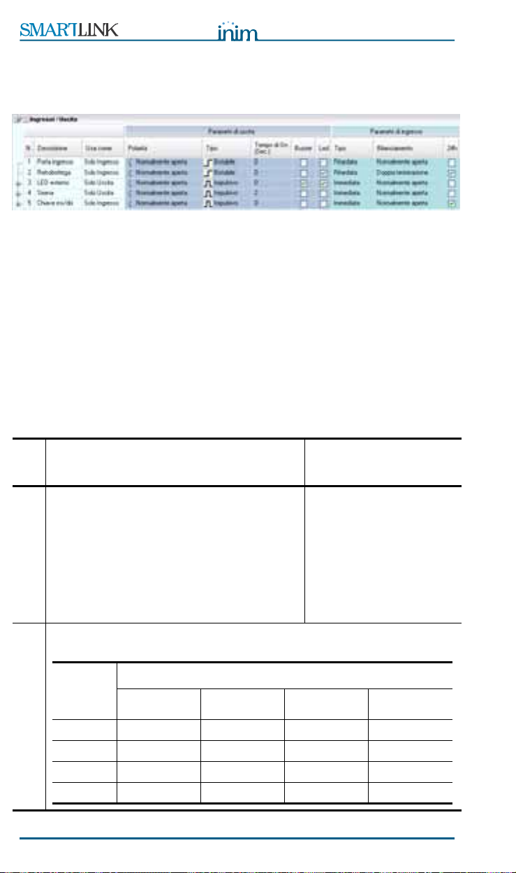
Figure 10 - Inputs/Outputs table
The SmartLink-P provides 5 terminals (IO1, IO2, IO3, IO4, IO5), which can
be used individually as inputs (channels) or outputs.
The Use as drop-down menu will allow you to select the operating mode of
the terminal. If you activate an output using DTMF tones over-the-phone
(refer to paragraph 8.11 Remote control of SmartLink-P via DTMF tones) , it
will be possible to check successful activation by means of the Input/Output
feature (refer to paragraph 8.7.3 Inputs/Outputs).
8.7.1 Inputs
The inputs can be used for devices with two statuses only (active-standby) or
for devices with three or four statuses (e.g. standby, alarm, tamper and
short-circuit).
The four statuses are determined by two balance resistors which determine
the three threshold windows. Each exceeded threshold generates an event
which can be associated with an outgoing Contact ID report, voice message
or activation of outputs and device constraint.
The SmartLink-P inputs determine the following conditions:
• Status 1: line open
• Status 2: line ended with a single 15KOhm resistor
• Status 3: line ended with two 15KOhm resistors in parallel (7.5KW)
• Status 4: line shorted to ground
The characteristics allow management of the normally closed (or open)
contacts and the balanced lines (EOL or DEOL), typical of intrusion control
panels (refer to paragraph 8.8 Programming the SmartLink-P as an intrusion
control panel).
Going above each threshold generates an event which can be associated with
a voice message, Contact ID report, activation of outputs and device
constraint.
At default the SmartLink is configured to use the first 4 terminals (IO1, IO2,
IO3, IO4) as inputs. For the factory default settings relating to the inputs,
refer to Appendix B.
32 Settings
Page 33

Installation and programming manual
8.7.2 Outputs
The Open-Collector, pulse or bistable outputs can also be programmed to
activate the external LEDs or buzzer. In this case, they will operate with
specific characteristics.
The outputs can be activated by:
• events generated by status changes on other outputs or by internal events
(for example: land-line down or low battery)
• DTMF tone sequences
8.7.3 Inputs/Outputs
The IN&OUT terminals can operate as inputs or outputs. This configuration
feature is useful when you wish to activate outputs by remote control and
verify the result (for example, via a voice message) without utilizing another
input channel.
For example you can:
1. Using DTMF tones, activate output 4 — programmed as normally open
and bistable.
2. Configure event 16 (Input 4 status 4 — which is line shorted to ground
of Output 2) to send a voice call and to toggle output 3 to ON status.
3. Result: the remote command will close output 4 to ground. The status
change will be considered the input of the event programmed to trigger
the “send call” and “activate output 3” actions.
Parameter Description Note
Description
Output -
Polarity
Output - Type
Output - ON
Time
Settings 33
The customizable name (identifier)
given to the terminal.
Output standby status Normally open, normally
closed (to ground).
If the output is a pulse output,
activation will change its status for
the set time only. If the output is a
bistable output, activation will
change its status but will not
restore until the output is
deactivated.
For pulse outputs only —
determines the pulse length.
Pulse or bistable.
For example, low battery
event, bistable: the
warning will persist until
the battery is properly
charged. Pulse: the output
generates a pulse to signal
low battery status.
Page 34

Installation and programming manual
Parameter Description Note
Output -
Buzzer
Output - LED
Input – Type
Input –
Balance
To be used when the output is
connected to an external buzzer. In
this case, activation generates an
audible signal (beep) which persists
for the entire ON status (if the
output is a pulse output — for the
set
ON Time
, if the output is a
bistable output — until standby
status is restored). During ON
Time, a signal between 0 and 5V @
1KHz frequency will be present on
the terminal.
To be used when the output is
connected to an external LED. In
this case, activation generates a
visual signal (LED ON) which
persists for the entire ON status (if
the output is a pulse output — for
the set
ON Time
, if the output is
a bistable output — until standby
status is restored).
Enabled only when the SmartLink-P
is used as an Intrusion control
panel.
Enabled only when the SmartLink-P
is used as an Intrusion control
panel.
If you want the LED to
blink, click on the
respective check box.
Blinks @ 2Hz frequency
(0.25 seconds ON an 0.25
seconds OFF). Do not click
on the check box, if you
want the LED to be solid.
See
paragraph 8.8
Programming the
SmartLink-P as an
intrusion control panel
.
Input – 24h
Enabled only when the SmartLink-P
is used as an Intrusion control
panel.
Input –
Threshold 1
The value of the balance resistor
which determines the transition
threshold from status 1 to status 2,
and triggers the status 2 event.
Input –
Threshold 2
The value of the balance resistor
which determines the transition
threshold from status 2 to status 3,
and triggers the status 3 event.
Input –
Threshold 3
The value of the balance resistor
which determines the transition
threshold from status 3 to status 4,
and triggers the status 4 event.
34 Settings
Page 35

Installation and programming manual
Parameter Description Note
Resistance
Calibration
You can view the value of the
resistance that the SmartLink-P
reads on a specific terminal by
clicking on the sensible area of the
terminal concerned.
The button used to calibrate an
input and reduce the effect of loss
of component characteristics.
a
Work carefully through the
following steps:
1. Connect a calibration
resistor (10K, 12K or 15K
as required, between
IN&OUT terminal
concerned and ground
(terminal 4).
2. Connect the SmartLink-P to
a computer.
3. Select the button in the
Resistance column: the
box will show the value
read on the terminal.
4. If the value differs greatly
from the value of the
resistor connected to the
terminal, proceed with the
calibration. If the values
are very similar, calibration
will not be necessary.
5. Otherwise, select
Calibrate: answer YES to
the confirm request.
6. Click on the value of the
resistor used then select
Ok.
SmartLink-P compares the
selected value and the
current value on the input.
It will indicate any notable
difference and request
confirmation to continue.
7. Wait 3-4 seconds: a
calibration done message
appears. Select the button
in the Resistance column
to verify the value on the
terminal after calibration.
Send the parameters to
SmartLink-P before
switching off. This is the
only way to make the
calibration definite!
Calibration is
recommended on systems
using dated components,
in order to allow signals
coming from these
components to have
values suitable to detect
exceeded balance
thresholds and subsequent
status changes.
You can use the View
button in the
Resistance
column at
any time to view the value
of the resistance on a
specific terminal. The
'
Terminal open!'
string
indicates a value of over
30K.
a. Patent pending
Settings 35
Page 36
Installation and programming manual
8.8 Programming the SmartLink-P as an
intrusion control panel
Figure 11 - Inputs/Outputs table
SmartLink-P can operate as an intrusion control panel by simply
programming the inputs and outputs accordingly.
1. Enable the SmartLink-P intrusion control panel option from the
Parameters, Intrusion control parameters table: in this way, input 5
will be set up automatically to manage the keyswitch (normally open).
2. Configure the other four terminals as 'inputs to monitor' and 'outputs to
activate'.
3. Configure the events in the Events table for each status of the two
inputs used.
To view an example of a layout, refer to Appendix A.
Para
meter
Inputs with the
generate the "status-change" event during the
programmed delay (defined in the
control panel parameters
of slow beeps emitted by the buzzer indicate
that the status change has been detected and
the programmed delay is running. Inputs with
Input – Type
the
Instant
instantly and will generate the respective event.
The line-balance type determines the logic of the intrusion control panel input
statuses:
Status
of
input
Status 1
Status 2
Input – Balance
Status 3
Status 4
36 Settings
Description Note
Delayed
attribute will signal status change
Normally
Standby Alarm Alarm Tamper
Alarm Alarm Standby Alarm
Alarm Alarm Short-circuit Standby
Alarm Standby Short-circuit Short-circuit
attribute will not
open
Intrusion
table). A series
balance
Normally
closed
For example, the Entrance
input is delayed long
enough for the user to
reach the arm/disarm
keyswitch of the intrusion
control panel at the
entrance/exit of the
premises.
EOL DEOL
Page 37

Installation and programming manual
Alarm Tamper
Alarm TamperAlarm Tamper
Para
meter
If
24h
is not selected, only Short-circuit and
Description Note
Tamper will be monitored during panel
disarmed status. If
24h
is selected, all
conditions will be monitored, even when the
panel is disarmed.
Input – 24h
DEOL
EOL
Figure 12 - Balance
For example, this option is
useful for duress and
device tamper reports.
Normally open/closed
8.9 Programming event generated actions
Figure 13 - Events table
The Events list is the heart of the SmartLink-P system. The events represent
everything the system is capable of recognizing, from external conditions
(e.g. input signals) and internal conditions (e.g. low battery).
The events can generate the following actions:
Settings 37
Page 38

Installation and programming manual
• Send Contact ID report
• Send voice message
• Activate/Deactivate outputs
• Constraint and commands
The SmartLink-P manages four status-change events per IN&OUT input (i.e.
20 events) and other pre-set events generated by SmartLink-P (e.g. low
battery).
If several events occur at almost the same time, SmartLink-P will create a
Call queue and will deal with the calls in chronological order.
For example, if an alarm is triggered by input (channel) IO1 which is
programmed to generate calls to the first 5 contact numbers in the
phonebook, the device will dial the numbers (1 to 5) in order. If another
alarm occurs in the meantime, even on another channel, the calls will be
placed in the call queue. If calls relating to various alarm events are queuing
to be sent to the same number, SmartLink-P will combine all the respective
alarm messages and send them in a single call.
Refer to paragraph 8.6 Setting up the SmartLink parameters for the settings
relating to the voice dialer, such as: call attempts, message playbacks, call
confirmation and others.
Parameter Description
No.
Description
Intrusion input
logic status
Save event
Event number
Event description
Enabled only when the SmartLink-P is used as an Intrusion
control panel. This shows the statuses (Standby, Alarm,
Short-circuit and Tamper) the input manages in accordance
with the balance type selected in the
table.
If selected, the event concerned will be saved to the
SmartLink-P event log with the respective date, time and
description. The log stores 32 events. Once the log is full, new
events will automatically overwrite the oldest events in the
log. The stored events are available for viewing in the
table, and can be viewed separately from the other
parameters. See paragraph 8.3.5 Viewing the Events log.
Inputs/Outputs
Log
8.9.1 Delete event programming
The event programming can be deleted, for example, if programming errors
occur.
To perform this operation, select, bottom left, Delete, click-on one or more
groups then select Delete: all the selected boxes will be deleted.
38 Settings
Page 39

Installation and programming manual
8.9.2 Send event-triggered voice message
(SmartLogos60 required)
Figure 14 - Events table - Voice messages
You can send one or more voice messages to a specific contact number, for
example, to warn the recipient that intrusion is occurring is underway.
To allow this, the voice messages must be set up as per the instructions in
paragraph 8.5.2 Setting up the voice dialer messages (SmartLogos60 board
required). In this way, the description of the message to send will appear in
the message list.
Parameter Description Note
Voice dialer
Voice
messages
Phone
numbers
Folder containing 'send voice
message' parameters. Double click
to open: columns containing the
successive parameters will appear.
Double click to close.
Check boxes corresponding to the
voice messages defined in the Voice
message table. The message
description appears when you mouse
over the respective number on the
tooltip bar. You can select several
voice messages to be played one
after another. For example, you can
record a single "address" message to
be added to all the event messages.
Check boxes corresponding to the
phone numbers for outgoing calls set
up in the
number description appears when
you mouse over the respective
number on the tooltip bar.
Phonebook
. The phone
=no parameter has
been set
=some parameters
have been set.
See the
numbers
choose whether the
message must reach only
one of the dialed phone
numbers or all of them
successfully.
Call all voice
option to
Settings 39
Page 40

Installation and programming manual
8.9.3 Send an event-triggered Contact ID report
Figure 15 - Events table - Contact ID
Each event can trigger and send a Contact ID report to a specific phone
number.
For example, an input zone alarm event to the Alarm Receiving Centre..
Parameter Description Note
Contact ID
dialer
Protocol
class
Event code
Qualifier
Phone
numbers
Note:
Folder containing Contact ID report
parameters. Double click to open:
columns containing the successive
parameters will appear. Double click
to close.
ContactID protocol class The event
protocol class must be approved by
the central station.
2 digit hexadecimal code The Code must be
New
for a new event,
for a cleared event. In report coding
New
=1 and
Restore
Check boxes corresponding to the
phone numbers for outgoing calls
set up in the
phone number description appears
when you mouse over the respective
number on the tooltip bar.
The code which allows the Alarm Receiving Centre to
recognize the system must be entered in the Codes list (refer
to paragraph 8.5.3 Setting up Caller ID codes).
Phonebook
Restored
=3.
. The
=no parameter has
been set
=some parameters
have been set.
approved by the central
station.
See the
Call all Contact
ID numbers
choose whether the
message must reach only
one of the dialed phone
numbers or all of them
successfully.
option to
40 Settings
Page 41

Installation and programming manual
Setting Contact ID at default
Select Default Contact ID bottom left: SmartLink-P will apply Contact ID
default configuration to all events.
The event default codes are DCS (Digital Communication Standard)
international reporting protocol, for example:
Event
Low battery 3 A2 1
Indicates
•3=trouble
•A2=Low Battery
• 1=New event
Note:
Protocol
class
You can create “model” solutions tailored to the needs of
specific central stations, for each solution you can:
1. select default Contact ID reporting protocol
2. customize the Codes to central station requirements
3. print the Contact ID table using
Event code Qualifier
File, Print
.
Programming the SmartLink-P as an intrusion control
panel
The event associated with status change on input 5 (arm/disarm intrusion
panel) does not have a Contact ID code.
The events associated with status change on the inputs will have Contact ID
codes which depend on the logic status of the input and its balance:
I n p u t l o g i c s t a t u s
Intrusion control
Protocol
class
Event
code
Qualifier
Alarm 1 3A 1
Standby 1 3A 3
Ta m pe r 1 4 4 1
Short-circuit 1 44 1
Settings 41
Page 42

Installation and programming manual
8.9.4 Activate an output in response to an event
Figure 16 - Events table - Outputs
Each event can activate/deactivate a pulse or bistable output.
To allow this, the outputs must be set up beforehand as per the instructions
in paragraph 8.7 Programming the Inputs and Outputs — IN&OUT. In this
way, the output description will appear in the selectable Outputs list.
For example, if an event occurs on an input connected to flood detectors, it
will be possible to cut off the water supply at the mains.
Attention:
Parameter Description Note
Outputs
ON
OFF
Bistable outputs (activated by events) do not deactivate
automatically when the event clears. You must program
deactivation by selecting the respective 'restore' event.
Or use the Simplified management bistable output. See
paragraph 8.7 Programming the Inputs and Outputs —
IN&OUT.
Folder containing the output activation
parameters. Double click to open:
columns containing the successive
parameters will appear. Double click to
close.
Check boxes corresponding to the outputs
configured in the
table. If selected, they will activate the
respective output. The output description
appears when you mouse over the
respective number on the tooltip bar.
Check boxes corresponding to the outputs
configured in the
table. If selected, they will deactivate the
respective output. The output description
appears when you mouse over the
respective number on the tooltip bar.
Inputs/Outputs
Inputs/Outputs
=no parameter
has been set
=some
parameters have
been set.
If the output is a
pulse output,
activation will change
its status for the set
time only.
Deactivation of a
pulse output ends
any ongoing pulse
signal, otherwise, it
has no effect.
42 Settings
Page 43

Installation and programming manual
8.9.5 Implement constraint after event
Figure 17 - Events table - Constraint
Each event can implement constraint and generate commands. For example,
a disarm event can also implement the Clear call queue action.
Parameter Description Note
Options
Clear call
queue
Periodic
warning
constraint
Hide outgoing
call
Folder containing Constraint
parameters. Double click to open:
columns containing the successive
parameters will appear. Double click to
close.
If selected, this event will interrupt the
ongoing call and cancel any event
generated calls.
If selected, this event will generate a
Programmable periodic event
If selected, the visual/audible ongoing
call signal will be hidden when the
event occurs:
•LED On
• Start call event
• End call event
If, for the
events, you select
these events will be saved even if the
audible/visual signal has been
excluded.
Start call
Save event
and
.
End call
,
=no parameter
has been set
=some
parameters have
been set.
For example, this
option is useful when
users want to stop
unnecessary calls
generated by false
alarms.
For example, if you
want to hide
SmartLink-P calls to
the Alarm receiving
Centre during a
robbery.
Settings 43
Page 44

Installation and programming manual
8.10 Programming periodic events
Figure 18 - Programmable events table
You can program recurring events and pre-set events. The Events list
provides two programmable events: a periodic event (e.g. send an 'All's well'
Contact ID report) and an expiration event.
Programming of this window is independent of all the other programming
pages in the software application and takes place when the Initialise button
is selected.
Parameter Description Note
Periodic event
Maintenance
event
Note: The examples are only suggestions. The programmable
The first
generated in accordance with the
set date and time. Successive
periodic events will be generated
in accordance with the number of
hours set for the interval
between events.
SmartLink-P will trigger the
Maintenance event
accordance with the set date and
time.
events are fully customizable.
Periodic event
will be
in
For example, to send an
'All's well' Contact ID
report to the Alarm
Receiving Centre..
SmartLink-P must be
connected to a
computer in order to
implement this
operation.
For example, to send a
'Maintenance' reminder
voice message to the
installer.
44 Settings
Page 45

Installation and programming manual
8.11 Remote control of SmartLink-P via
DTMF tones
SmartLink-P is capable of carrying out over-the-phone commands in DTMF
sequence, during both incoming and outgoing calls for:
• Arm/Disarm Intrusion Control Panel
• Input status enquiry
•Activate output
•Clear call queue
If the Enable PSTN (land line) answerphone option is enabled,
SmartLink-P will respond to incoming DTMF tone sequences over the landline (PSTN), otherwise, DTMF tone sequences will be ignored.
Note:
If you are making an status enquiry call to SmartLink-P, or you are receiving
for example a 'flood alarm' voice call from SmartLink-P, you will automatically
access DTMF mode which, in the case of the 'flood alarm' call, will allow you
to turn off the water supply at the mains.
For land line (PSTN) calls, verify the setting of the
call
option. See paragraph 8.6 Setting up the SmartLink
parameters.
Double
8.11.1 Sending the DTMF tone sequence
If you are calling SmartLink-P:
1. Make the call.
If SmartLink-P is calling you:
1. Press ‘#’
Access the DTMF menu:
2. Wait for 4 feedback beeps (access confirmed)
3. Press ‘#UserCode#’ (e.g. ‘#005122#’) and wait for 2 feedback beeps
(access confirmed). If the code entry is invalid, access will be denied and
indicated by an audible error signal.
4. Press ‘#’ to access the DTMF menu
5. Type in a Control code (‘0’, ‘1’, ‘4’, ‘5’)
6. Work carefully through the specific instructions for each code, as follows.
Note:
Note:
Settings 45
If (from the
code
option is enabled, and you receive a call from the
device, you can omit the user code from the sequence (i.e.
skip steps 3, 4 and 5).
Press ‘#’ at any point to go back to the main menu or ‘*’ to
end the call.
Parameters
table) the
DTMF menu without
Page 46

Installation and programming manual
8.11.2 Arm or disarm the system (#1)
1. Press ‘1’ and wait for a feedback beep. If SmartLink has not been
programmed as an intrusion control panel, it will emit a negative
feedback signal at step 5. of the DTMF sequence.
2. Press ‘1’ to verify the status of the intrusion-control panel or ‘2’ to
change it.
3. If you hear a beep, the intrusion-control panel is disarmed. If you hear a
2 beeps, the intrusion-control panel is armed.
4. Press ‘#’ to go back to step 5. of the DTMF sequence.
8.11.3 Input status enquiry (#4)
1. Press ‘4’ and wait for 2 feedback beeps.
2. Select the input by pressing the respective key: ‘1’ to ‘5’.
3. The number of beeps emitted (1 to 4) corresponds to the status of the
input (Status1, Status2, Status3 or Status4).
4. Select another input by pressing the respective key: ‘1’ a ‘5’ or press ‘#’
to go back to step 5. of the DTMF sequence.
8.11.4 Activating outputs (#5)
1. Press ‘5’ and wait for 2 feedback beeps.
2. Select the output by pressing the respective key: ‘1’ to ‘5’. If the
selected output is associated with and 'Inhibit' event, you will hear an
error signal (bop) and it will be necessary to select another output.
3. If you hear 1 beep, the output will toggle to OFF status when you press
‘#’. If you hear 2 beeps the output will toggle to ON status when you
press ‘#’.
4. Select another output by pressing the respective key: ‘1’ a ‘5’ or press
‘#’ to go back to step 5. of the DTMF sequence.
Note:
The output will not change status when you press the number
key, but only when you press # to confirm the operation. You
cannot control an output which is associated with one or more
events from n. 21 to n. 36. If you attempt to control it, the
device will emit an audible error signal (
bop
).
8.11.5 Clear call queue and end ongoing call (#0).
After initialising the menu, type in “#0”: the device will end the ongoing call
and cancel the calls in the queue.
8.11.6 End ongoing call
After initialising the menu, type in ‘*’: the device will end the ongoing call.
8.11.7 Go back to main menu
After initialising the menu, type in ‘#’: the device will get ready to receive
other DTMF tone commands.
46 Settings
Page 47

Installation and programming manual
Appendix A
Wiring diagram of an intrusion-control
panel
Wiring diagram of an intrusion-control panel 47
Page 48

Installation and programming manual
Caption
• All resistors @ 15K
• Normally-open keyswitch contact
• Sounder/Flasher activated by "positive removed"
• Device must be Earthed (see terminal 12)
Input programming:
IO1-IO2
Type : D e l ay e d
Balance: DEOL
Events 1, 2, 4, 5, 6, and 8 switch output 4 ON
Events 3 and 7 switch output 4 OFF
IO3
Balance: EOL
Events 9, 11 and 12 switch output 4 ON
Event 10 switches output 4 OFF
Outputs programming:
IO4
Type : B i s ta b l e
Polarity: normally open
IO5
Already programmed by the selected parameter Enable intrusion control
The diagram illustrates an application with:
• Two DEOL zones for:
- Connect two detectors (e.g. PIRs, magnetic contacts, etc.).
- Device alarm and tamper must refer to the same input
• One balanced tamper zone for:
- external sounder/flasher tamper detection;
- frontplate removal detection.
• One alarm output, where the open-collector output controls a single
polarity changeover relay for:
- self-powered external sounder/flasher command;
- internal sounder/flasher command;
• keyswitch input to arm/disarm intrusion control panel.
48 Wiring diagram of an intrusion-control panel
Page 49

Installation and programming manual
Appendix B
Default settings
SmartLink-P default settings
Settings:
• The first 4 terminals (IO1, IO2, IO3, IO4) are input channels.
- IO1 and IO2 are programmed to call the first 5 contact numbers in the
phonebook, if they close to ground.
- IO3 and IO4 are programmed to call the second 5 contact numbers in
the phonebook, if they close to ground.
- The fifth terminal (IO5) is a normally open, bistable output which signals
PSTN line-down and Low battery conditions.
• All events saved to Events log.
Enabled Parameters:
• Instant signaling of PSTN line-down conditions
• Message playbacks set at 5
• Call attempts set at 5
• Simplified management of bistable outputs
Codes:
• Installer code 0000
• User code 0001
• Customer code 0001
Restoring factory default settings
Short-circuit pins 2 and 3 of the DB9 connector and power up the board. After
1 second the board parameters, including any input calibrations, will be
restored to default settings.
Default settings 49
Page 50

Installation and programming manual
Appendix C
Order codes
Following are the order codes of INIM Electronics s.r.l. products:
Code Description
DCMIINI0SLINKP Installation and Programming manual
IPS12015DT Switching power supply/battery charger (accessory
item)
Link232F9F9 RS232 link
LinkUSB232CONV RS232-USB adaptor
SmartLeague Programming software, Windows ambient
SmartLink-BG Reserve line generator and GSM network dialer in
SmartLink-BGP Reserve line generator and GSM network and PSTN
SmartLink-G Reserve line generator and GSM network dialer in
SmartLink-GP Reserve line generator and GSM network and PSTN
SmartLink-GWB Reserve line generator and GSM network dialer
SmartLink-P Land line (PSTN) voice dialer
SmartLogos60 Voice board — 60 seconds, eight messages
cream-coloured casing
dialer in cream-coloured casing
black casing
dialer in black casing
without casing
50 Order codes
Page 51

Installation and programming manual
Notes:
Notes: 51
Page 52

INIM Electronics s.r.l.
via Fosso Antico, Centobuchi
63033 Monteprandone, AP - Italy
Tel. +39 0735 70 50 07
Fax. +39 0735 70 49 12
email: info@inim.biz
www.inim.biz
AZIENDA CERTIFICATA ISO9001:2000
DCMIINE0SLINKP-R100-20091222
 Loading...