

INIM Electronics SmartLevel SPS24040, SmartLevel SPS24140 Installation And Programming Manual
Page 1

Installation and Programming manual
1
SmartLevel
Power supply station
Installation and Programming manual
EN 54-4
0051-CPD-0170
0051-CPD-0171
Page 2

2 Copyright
Installation and Programming manual
Copyright
The information contained in this document is the sole property of INIM Electronics s.r.l. No part
may be copied without written authorization from INIM Electronics s.r.l.
All rights reserved.
European directive compliance
This power station has been designed and developed to the highest standards of quality and
performance implemented by INIM Electronics.
This power station must be installed in accordance with the instructions described in this manual
and in compliance with the laws in force.
All power stations from the SmartLevel series are EN54-4 compliant.
All power stationls from the SmartLevel series, and all accessory items and special functions
have IMQ Sistemi di Sicurezza certification, unless otherwise stated.
DCMIINIESPS24-R121-20120210
Page 3

Installation and Programming manual
Table of contents 3
Table of contents
Copyright ............................................................................ 2
European directive compliance ............................................... 2
Table of contents.................................................................. 3
Chapter 1 Introduction......................................................................... 5
1.1 Application and use 5
1.2 The system parts and definitions 6
1.3 The SmartLevel power supply stations 6
Chapter 2 General information .............................................................. 7
2.1 In-box documentation 7
2.2 Document details 7
2.3 Software information 7
2.4 Operator qualifications and Access levels 7
2.5 Intellectual property rights 7
2.6 Disclaimer 7
2.7 Recommendations 8
2.8 Testing the apparatus 8
2.9 Note to the installer 8
2.10 Technical support 8
2.11 Conventions 8
2.12 Manufacturer's name and address 9
2.13 Device labels 9
2.14 Warranty 9
2.15 Safety laws 10
Chapter 3 Device management ........................................................... 11
3.1 Transport of goods 11
3.2 Storage conditions 11
3.3 Unpacking the device 11
Chapter 4 Functions and features ........................................................ 12
4.1 Controlling the Outputs 12
4.2 Controlling the outputs via the Inputs 13
4.3 How to use the power supply station 13
4.4 Protection circuit 14
Chapter 5 Technical description........................................................... 15
5.1 Internal components 15
5.2 Technical specifications 16
Chapter 6 The Frontplate ................................................................... 17
Chapter 7 Installation instructions ....................................................... 18
7.1 Wall mounting 18
7.2 RS485 BUS wiring 18
7.3 Connecting the output channels 19
7.4 Connecting the FAULT output 19
7.5 Connecting the Mains 19
7.6 Connecting the batteries 20
7.7 The thermal probe 21
Chapter 8 Powering up the system ...................................................... 23
Chapter 9 Viewing the display screens ................................................. 24
9.1 Presentation screen 24
9.2 Output status screen 24
9.3 Main menu 25
9.4 Faults screen 25
Page 4

4 Table of contents
Installation and Programming manual
Chapter 10 Programming and maintenance from the panel....................... 26
10.1 Programming operations 26
10.2 Direct Maintenance 27
10.3 Closing a Programming/Maintenance session 27
Chapter 11 Troubleshooting ................................................................. 28
11.1 Current faults list 28
11.2 “Output protection” fault 28
11.3 Battery Faults 29
11.4 Other faults 29
Appendix A Maintenance ...................................................................... 30
Appendix B Order codes....................................................................... 31
Page 5

Installation and Programming manual
Introduction 5
Chapter 1
Introduction
Note: The power supply stations described in this manual have been designed and developed to the highest
standards of quality, reliability and performance. All product components are capable to application
requirements and able to operate in compliance with the related technical specifications when the
temperature external to their enclosures complies with Category 3k5 of EN60721-3-3:1995.
1.1 Application and use
The SmartLevel unit is a constituent part of your fire detection system and is capable of supplying power to
the remote loads of the system. It supplies power to remote loads such as: fire-door magnets, sounders,
emergency signs, linear smoke detectors.
Note: The SmartLevel power supply station is EN54-4 compliant and specifically EN 54-4:1997 A2 which
includes a test regarding the internal resistance of the batteries.
Main features:
• User interface comprising display, buttons and buzzer
• 3 controlled outputs
• Fault relay
• Direct connection to RS485 BUS
The SmartLevel can operate in stand-alone mode using the fault signaling output and on-board data, or
combined mode using the RS485 BUS of an INIM Electronics fire detection system (refer to Chapter 4 -
Functions and features).
Figure 1 - Example of a typical application
Remote control via the RS485 BUS
3 output channels
Maximum power output 0.8A for SPS24040 and 3A for SPS24140
of an INIM fire-detection panel
Page 6

6 Introduction
Installation and Programming manual
1.2 The system parts and definitions
Power supply module: a module, connected to the mains 230 Vac, which supplies a stabilized voltage @
24 V (27.6 V) to the system and the charge source to the batteries. The power-supply module is located
below the mother board and is EN54-4 compliant. The mains voltage (230 Vac) is the primary power
source of the system. See also paragraph 7.5 Connecting the Mains.
Batteries: the secondary power source of the system. The power supply station enclosure houses two lead
batteries @ 12V 7Ah (depending on the model) connected in series. The system monitors the battery
status (efficiency and charge). A fault signal will be generated when voltage overload/underload or
inefficient battery conditions occur (Appendix A2). In the event of primary power (230 Vac) failure, the
batteries will take over, however, they will shutdown automatically if the blackout persists. The automatic
battery shutdown feature prevents irreparable damage to the batteries. See also paragraph 7.6 Connecting
the batteries.
Thermal probe: an accessory tool connected to the panel and attached to the battery pack. This device
monitors the temperature of the battery pack and regulates the battery charge accordingly. See also
paragraph 7.7 The thermal probe.
RS485 BUS: 4 wire BUS which allows the power supply station to be connected directly to INIM fire
detection panels (SmartLoop, SmartLight and SmartLine). Four pole shielded-twisted cable must be used
for all connections. See also paragraph 7.2 RS485 BUS wiring.
1.3 The SmartLevel power supply stations
Product models:
• SPS24040 - Power-supply unit with internal 1.4A @ 27.6V switching power-supply module and housing
for 7Ah, 12V batteries
• SPS24140 - Power-supply unit with internal 4A @ 27.6V switching power-supply module and housing for
17Ah, 12V batteries
Page 7

Installation and Programming manual
General information 7
Chapter 2
General information
2.1 In-box documentation
The power supply station comes with a combined "Installation and Programming Manual" (this document).
If you require extra copies, please contact INIM electronics offices and quote the order number shown in
Appendix B Order codes.
2.2 Document details
• Title: SmartLevel installation and programming manual
• Edition, Issue: 1.21
• Month and year of issue: February 2012
• Manual code: DCMIINIESPS24
• Addressees: the installer company, technical assistance technicians
2.3 Software information
• SmartLevel Firmware Version: 1.0.x
2.4 Operator qualifications and Access levels
The SmartLevel power supply station has been especially designed to comply with EN-54-4 (including the
provisions of EN 54-4:1997/A2:2006). User Access
Level 1: Building occupants
Using the graphic screens, building occupants can view the status of the outputs and the output
voltage. Furthermore, they can view the Events Log, silence the power-supply buzzer, test the
LEDs and reset the power supply station.
Level 3: Authorized technicians appointed by the Installer company.
These technicians can, by means of the necessary tools, remove the frontplate of the power
supply station. They can insert the respective jumpers in order to access and carry out
programming and maintenance. Processing is inhibited during programming sessions,
therefore, the device will be unable to generate any signals whatsoever.
Level 4: Technicians employed by the Manufacturer (INIM Electronics s.r.l.).
These technicians can, by means of special tools, repair or replace the device components.
Note: This manual is for Authorized technicians (Level 3), however, it also describes some information
regarding the end user (level 1).
2.5 Intellectual property rights
The information contained in this document is private property. All rights reserved.
No part of this document may be copied, whether totally or partially, unless expressly authorized in writing
by INIM Electronics, in particular the parts regarding the device specified in paragraph 2.13 Device labels
2.6 Disclaimer
INIM Electronics s.r.l. shall not be responsible for damage arising from improper application or use.
Only qualified personnel (refer to Terminology) should touch this device. Installation must be carried out
strictly in accordance with the instructions described herein, and in compliance with the local fire code in
force.
Page 8

8 General information
Installation and Programming manual
2.7 Recommendations
INIM Electronics recommends that the apparatus be tested on a regular basis (refer to paragraph 2.8
Testing the apparatus).
2.8 Testing the apparatus
This apparatus has been designed to the highest standards of quality and performance. However, it may
fail to function as intended due to the failure of a component. Most problems that prevent the apparatus
from operating as intended can be found by regular testing and maintenance (refer to Appendix A
Maintenance).
2.9 Note to the installer
In order to provide adequate protection and instructions for proper use, you (the installer) should
be familiar with the operating procedure of this device. As the only individual in contact with system users,
it is your responsibility to instruct them on how to use this device properly.
2.10 Technical support
Our professional engineers are readily available to assist you. Call us, and you will be connected right away
to a person who will answer all your questions and provide you with full technical support.
2.11 Conventions
2.11.1 Terminology
Power supply unit: refers to the device defined in paragraph 2.13 Device labels.
Left, right, behind, above, below: refer to the directions as seen by the operator in front of the mounted
device.
Qualified personnel: those persons whose training, expertise and knowledge of the laws and bylaws
regarding service conditions and the prevention of accidents, are able to identify and avoid all possible
situations of danger.
Press: click on a video button, or press a key on the panel keypad.
2.11.2 Graphic conventions
Following are the graphic conventions used in the text. For a description of the graphic conventions relating
to the interface, refer to Chapter 6 - The Frontplate.
Note: The detached notes contain important information regarding the subject in the respective text.
Attention: The attention prompts indicate that total or partial disregard of the procedure could damage
the connected devices.
Danger: The danger warnings indicate that total or partial disregard of the procedure could injure the
operator or persons in the vicinity.
Conventions Example Description
Text in Italics
See
paragraph 5.1
Internal
components
.
Text in italics: indicates the title of a chapter, section, paragraph,
table or figure in this manual or other published reference.
[Uppercase letter] [A] Represent the device parts or video objects.
BUTTON Ok, Esc Computer or user interface keys.
Page 9

Installation and Programming manual
General information 9
2.12 Manufacturer's name and address
INIM Electronics s.r.l.
Via Fosso Antico, Centobuchi
63076 Monteprandone (AP) - Italy
+39 0735 70 50 07
+39 0735 70 49 12
info@inim.biz - www.inim.biz
2.13 Device labels
Figure 2 - Data label
Figure 3 - CE mark
2.14 Warranty
INIM Electronics s.r.l. warrants that for a period of 24 months from the date of installation, the product
shall be free of defects in materials and workmanship. The warranty applies only to defects in parts and
workmanship relating to normal use. It does not cover:
• Improper use or negligence
• Damage caused by fire, flood, wind or lightning
•Vandalism
• Fair wear and tear
Inim Electronics s.r.l. shall, at its option, repair or replace any defective products. Improper use or use for
purposes other than those mentioned herein will void the warranty. For the full details and conditions
regarding the warranty, refer to your purchase order.
LBDTIN4ASPS24040
I
230V~ -15% + 10%
Power / Alimentacion
50/60 Hz
Consumo /
Consumption / Consumo
0.5 A
Isolamento /
Isolation / Aislamiento
Classe
Approvato /
Approved / Aprobado
EN54-4
MADE IN ITALY
SPS24040
0051 CPD 0170
02/2012
Alimentazione /
0051
08
0051 - CPD - 0170
Power supply station
SmartLevel
SPS24040
EN54-4: 1997/ A2: 2006
Power: 230 Vac -15% +10%,
50/60 Hz
Consumption: 0.5 A
Isolation class: I
0051
08
0051 - CPD - 0171
Power supply station
SmartLevel
SPS24140
EN54-4: 1997/ A2: 2006
Power: 230 Vac -15% +10%,
50/60 Hz
Consumption: 0.9 A
Isolation class: I
Page 10

10 General information
Installation and Programming manual
2.15 Safety laws
The aim of the instructions in this section is to ensure that the device is installed and handled properly. This
chapter contains vital information. You (the installer) should be familiar with this section and bring each
item herein to the attention of the end-users.
2.15.1 Compliancy
The SmartLevel power supply station has been especially designed and manufactured to comply with EN
54-4 Fire detection and signaling systems - Power supply devices and the provisions in EN54-4:1997/
A2:2006.
2.15.2 Managing electronic devices
The normal motions of any person may generate electrostatic potential of thousands of volts. Discharge of
this current through semiconductor devices during handling may cause serious damage which although
may not be immediately evident may reduce the reliability of the circuits.
If located in their housings, the electronic circuits of INIM Electronics products are highly immune to
electrostatic discharge.
• Do not expose the circuits to damage caused by unnecessary handling.
• When removing or handling circuit boards, hold the board edges only.
• Do not touch the electronic components, the printed circuits or the metal parts of the connectors.
• Do not hand the board to another person without first ensuring that you both have the same
electrostatic potential. This can be achieved by simply shaking hands.
• Place the board on an anti-static surface or a conductor surface with the same potential.
Further information regarding procedures relating to safety when working with electronic devices can be
found in Directive IEC 60147-0F.
2.15.3 Connecting the device
In order to provide adequate protection and instructions for proper use, security professionals (Installers
and maintenance technicians) must be familiar with the operating procedure of this device.
Please read the instructions carefully before installing the device.
Before first power-up, be sure that the earth connection has been completed properly on the respective
terminal.
The recommended minimum wire cross section for the earth connection is 2.5 mm
2
, that is, unless
otherwise stated in accessory documentation.
2.15.4 Replacement and disposal of used devices
Replacement
When replacing used devices, disconnect the devices concerned then complete the connections of the new
devices in accordance with their instructions.
In order to avoid short-circuits, take all the necessary precautions when removing used batteries.
Disposal
Do not burn used electronic devices, or allow them to pollute the environment (countryside, rivers, etc.).
Electronic devices must be disposed of in a safe environment-friendly way.
When disposing used devices or batteries, contact your local municipal offices for information regarding
their disposal.
Page 11

Installation and Programming manual
Device management 11
Chapter 3
Device management
3.1 Transport of goods
Care must be taken to avoid accidental damage during transport. The boxes should be placed in such a way
as to avoid knocks and falls, and special care must be taken to protect the devices from extreme heat and/
or cold.
3.2 Storage conditions
Temperature limits
• -10° / +55°C for transport and storage
• -5° / +40°C operating temperature
3.3 Unpacking the device
The goods must be unpacked with care. All waste packaging materials must be disposed of in compliance
with the local laws and bylaws in force.
The package contains the SmartLevel power supply station in a metal enclosure.
Note: The lead batteries are not included. Be sure you have them on hand before starting.
When you remove the four screws and metal-frontplate, you will find:
• The SmartLevel motherboard, mounted on a plastic support which bridges the two sides of the metal
enclosure.
• The power-supply module mounted on the backbox. The power-supply module is already connected to
the SmartLevel motherboard.
• A plastic bag containing the battery wires.
The thermal probe (battery-charge optimizer) is an accessory item which must be purchased separately
(refer to Appendix B Order codes).
Page 12

12 Functions and features
Installation and Programming manual
Chapter 4
Functions and features
4.1 Controlling the Outputs
The power-supply outputs can be controlled locally, via the on-board inputs B1, B2 and B3 or remotely, via
the RS485 BUS of an INIM Fire detection panel.
The outputs follow the "OR" logic of the status of their command inputs, refer to the following Table.
You can define the standby status of each output using the Booster option in the programming menu (refer
to paragraph 10.1.1 Setting up the Booster parameters):
1. Standby-ON
Under these circumstances, there will be 24V (ON) across the terminal when the output is in standby
status and 0V (OFF) when the output activates. This is the setting at default.
2. Standby-OFF
Under these circumstances, there will be 0V (ON) across the terminal when the output is in standby
status and 24V (OFF) when the output activates.
You can also classify the output as monostable, in this way, it will be possible to define the output activation
time (ON Time). Once the set activation time expires, the output will restore to standby status
automatically but cannot be re-activated until the cause of activation clears.
If the activation time is not defined (“--”), the output will restore to standby status only when the cause of
activation clears.
Figure 4 - Output activation
Note: The outputs will be blocked automatically when you insert the programming jumper.
Command input Remote command via RS485 BUS Output
Open (standby) OFF (default) Standby
Open (standby) ON Active
Closed (active - default) OFF (default) Active
Closed (active - default) ON Active
OR
Station
inputs
BUS
RS485
OUTPUT
ACTIVE
Standby-ON Standby-OFF
0V 24V
Page 13

Installation and Programming manual
Functions and features 13
4.2 Controlling the outputs via the Inputs
Outputs OUT1, OUT2 and OUT3 are controlled respectively by inputs B1, B2 and B3.
The inputs are normally open (standby status), therefore, activation occurs when they are short-circuited
to GND.
4.3 How to use the power supply station
4.3.1 Stand-alone
In this operating mode the power-supply station is self-controlled, therefore, the outputs are managed via
the inputs. Fault conditions are signaled through the fault relay (FAULT output), which switches from
standby status to active status when faults occur.
4.3.2 Combined with an INIM Fire detection panel
There are two ways of connecting power supplies to INIM Fire detection panels, via:
•Loop connection
• RS485 BUS connection
Loop connection
This connection method allows the fire-defection panel to manage the power-supply outputs and fault
signals. The power-supply stations must be connected to the loop via one or more input/output modules
located inside the power supply station enclosure. The details of fault events can be viewed on the power
supply station display.
The following wiring diagram shows a loop connection using an input/output module of the INIM Electronics
ENEA series.
Figure 5 - Wiring diagram of a loop connection using a EM312SR module
Connecting the power supply station to an RS485 BUS
SmartLevel power-supply units are equipped with terminals which allow direct connection to the RS485
BUS of INIM fire detection panels. If any other devices are connected to the RS485 BUS, the power
supplies must be connected in parallel to them. The INIM fire detection panel will communicate with the
power supplies using a noise-immune communication protocol.
This connection method is designed to keep the control panel voltage isolated from the power-supply
station voltage.
The INIM fire-detection panel can enroll the power supply station, control its outputs as described in the
Table in paragraph 4.1 Controlling the Outputs and monitor its status (output and fault status). For details
regarding the respective wiring refer to paragraph 7.2 RS485 BUS wiring.
Note: If the power supply station is the last device on the BUS, you must insert the jumper JP3 in the EOL
position.
RED
RED ORANGE
GOLD
Page 14
14 Functions and features
Installation and Programming manual
4.4 Protection circuit
The outputs are protected against short-circuit and overload (Imax=3.7A) by a protection circuit (circuit
breaker) which operates in the same way as a fuse.
If the protection circuit intervenes, the power supply station will signal the fault and protect the interrupted
line before making three attempts to re-activate it.
• If the fault condition (overload) clears, the output channel voltage will restore to 24V (ON).
• If the fault condition is still present after the third attempt, the power supply station will leave the
output at 0V (ALERT).
The three attempts to re-activate the line will be carried out at 2, 5 and 10 seconds from the start of the
fault.
In the event of a fault, follow the procedure described in paragraph 11.2 “Output protection” fault.
Figure 6 - OUT1 channel protected by fuse
Note: The protection circuit will continue to operate even when the PROG jumper is inserted.
OUT1 OUT2 OUT3
Page 15

Installation and Programming manual
Technical description 15
Chapter 5
Technical description
5.1 Internal components
Figure 7 - The SmartLevel motherboard
Main components
[A] RS485 BUS terminals for direct connection to INIM Fire detection panels
[B] Input terminals (B1, B2, B3)
[C] Output channel terminals (OUT1, OUT2, OUT3)
[D] RS485 BUS EOL jumper
[E] Voltage-free fault relay (FAULT)
[F] Connector for the earth wire of the power-supply module
[G] Power-supply module connector
[H] Battery connector
[I] Thermal probe connector
[J] Earth-fault bypass jumper—if the jumper is removed, earth faults will not be signaled.
[K] Programming jumper (PROG)
[L] Buzzer
C
D
E F
G H
I
J
K
L
A B C C
Page 16

16 Technical description
Installation and Programming manual
Note: INIM s.r.l. reserves the right to change, replace, in part or entirely, the components not strictly relating
to the installation procedure described in Chapter 7 - Installation instructions.
5.2 Technical specifications
Specifications SPS24040 SPS24140
AC power 230 Vac (-15% + 10%) 50/60 Hz
Maximum current draw 230V 0.5 A 9 A
Maximum nominal current draw of the power supply
station (I max. a)
0.8 A 2.8 A
Maximum nominal current draw of the power supply
station while battery charging is not required (I max. b)
1.2 A 3.6 A
Minimum current draw 0 A 0 A
Nominal output voltage 27.6 V
Maximum battery-charge current 0.4 A 1 A
Battery specifications 2 x 12V, 7 Ah 2 x 12V, 17 Ah
2 x 12 V/7 Ah YUASA NP-12 FR or similar with case
flame class UL94-V2 or higher
Output voltage 18V - 27.6V
Switching power-supply fuse (F2) F 6.3 A 250V F 8 A 250V
Power-supply fuse (F1). Replacement of this fuse must
be caried out at factory.
T 3.15 A 250V T 3 A 250V
Maximum output current ripple 1%
Operating temperature -5°C ... 40°C
Dimensions 325 x 325 x 80 mm 497 x 380 x 87 mm
Weight 2.8 6
Page 17

Installation and Programming manual
The Frontplate 17
Chapter 6
The Frontplate
Figure 8 - User Interface
Keys
[A]
S/T/Ok/Esc
Navigate through the menus on the display. The way these keys work depends on the
context. Refer to Chapter 10 - Programming and maintenance from the panel.
LED ON Solid: ON Blinking: Note
[B] Display LCD Refer to Chapter 9 - Viewing the display
screens.
[C] GUASTO
(giallo)
Indicates an active
fault condition. The
display will provide
the fault details.
Indicates a restored
fault condition in
memory. To view the
restored fault condition
details, consult the
events log using the
Main menu (Level 1-Building occupants).
The fault memory will clear automatically
(LED Off) when the control panel resets
(Level 1).
[D] UNITA’
LOGICA
(giallo)
Indicates that the
control panel CPU is
not operating
properly. The power
supply station must
be returned to the
manufacturer for
repair.
Indicates that the CPU
has re-initialized (due
to control panel
shutdown or a fault
condition).
Danger: If the CPU LED
“blinks”, the efficiency
of entire system must
be tested. The CPU LED
will go Off when the
control panel resets
(Level 1).
[E] ON
(verde)
Indicates that the
system is operating
(On).
This LED will go Off in the event of
combined primary (230 V ac) and
secondary (batteries) power failure.
A
B
C
D
E
Page 18

18 Installation instructions
Installation and Programming manual
Chapter 7
Installation instructions
7.1 Wall mounting
1. Before attaching the backbox to the wall, pull the wires through the wire entry and ensure they do not
get in way of operations.
2. Using the wall plugs, attach the backbox to the wall.
Danger: Do not to drill in the vicinity of electrical wiring, heating ducts and plumbing.
7.2 RS485 BUS wiring
Figure 9 - Connecting the RS485 BUS
1. Use a 4 pole shielded-twisted cable.
2. The cable length between the INIM panel and the SmartLevel power supply station must not exceed 1000m.
3. Connect one end of the cable shield to the control panel earth terminal.
Note: The terminals of the SmartLevel power-supply module are isolated electrically from the RS485 BUS of
the fire-detection panel.
In order to allow the fire-detection panel to distinguish between the various SmartLevel power-supply units
on the RS485 BUS, you must assign a different address to each. When assigning addresses refer to
paragraph 10.1.3 Addressing the power supply station on the RS485 BUS.
The end-of-line jumper (JP3) should be in the EOL position only when the power supply station is the last
device on the RS485 BUS.
Figure 10 - Jumper positions
SmartLetUSee/LCD
REPEATERS
SmartLevel
POWER STATION
SmartLine-EXT
EXTINGUISHING
CONTROL PANEL
SmartLoop
CONTROL PANEL
EOL jumper position for the end-
of-line power supply unit
Jumper position for power-
supply units along the line
Page 19

Installation and Programming manual
Installation instructions 19
7.3 Connecting the output channels
Outputs OUT1-2-3 supply 24V (27.6V) and a maximum current of 0.8A for the SPS24040 model and 2.8A
for the SPS24140 model. These outputs can be used to power external devices.
These outputs can be managed via inputs B1, B2, B3 or via the RS485 BUS of an INIM fire-dectection panel
(refer to paragraph 4.1 Controlling the Outputs).
Use NON-shielded cable. The wire section should be compatible with the wire length and load connected to
the output.
7.4 Connecting the FAULT output
The FAULT output provides a voltage-free terminal which switches 1A 30V loads. The relay is energized
during standby status and closes its common contact to NC. During fault events, the NC contact opens and
the common contact closes to NO. The common contact closes to NC only when all fault conditions clear or
when the PROG jumper is inserted.
7.5 Connecting the Mains
The power-supply module (located under the motherboard) provides the power source to the entire system
and recharges the batteries.
The power-supply module must be connected to a separate line on the electrical switch board. The line
must be protected by a fire-code compliant circuit breaker.
The earthing system must be compliant with the local safety laws in force.
7.5.1 Technical specifications
• Primary power source: 230 V ac (-15% + 10%) 50/60 Hz
• Maximum current draw: 0.5 A for the SPS24040 and 0.9 A for the SPS24140
7.5.2 Wiring
Figure 11 - Connecting the Mains
Danger: Ensure that the Mains power is switched OFF before starting this procedure.
1. Connect the wires to the power-supply terminal board [A].
2. Using a plastic cable tie, bunch the wires together and attach them firmly to the cable hook [B] on the
backbox.
Attention: Wiring circuits must not be commingled without proper separation. Adhere to the connection
wiring in the diagram.
A
B
Page 20

20 Installation instructions
Installation and Programming manual
7.6 Connecting the batteries
The enclosure provides housing for two 12V lead batteries: 7 Ah for the SPS24040 model and 17 Ah for the
SPS24140 model. The two batteries must be connected in series, in such way as to supply 24 V.
Using the battery connection wire, connect the two batteries together then connect the batteries to the
power-supply module using the respective wire (included):
Figure 12 - Connecting the batteries
1. Connect the connection wire [A] to the two batteries.
2. Connect the wire [B] to the batteries.
Attention: Ensure that cable polarity is correct.
3. Connect the battery wire connector [C] to the power-supply module.
Attention: Ensure that connector polarity is correct.
The batteries are the secondary power supply of the system. The power supply station monitors the battery
status (efficiency and charge). The battery-test circuit of the power supply station operates as follows:
• Efficiency test
The battery-test circuit checks the efficiency of the batteries by simulating load current demand at 10
minute intervals. If the batteries fail to meet the load demand, the power supply station will signal a
Batt.discon. fault.
Additionally, the efficiency of the batteries is gauged by the value of their internal resistance (in
compliance with EN54-4:1997/A2). If this resistance reaches 2 Ohm, the power supply station will signal
a “
Batt.inef.” fault.
• Battery test
The battery-test circuit monitors the battery status (efficiency and charge) continuously. The battery-test
circuit can detect anomalies such as:
- A high charge voltage (“
Overload.”). This is signaled when the battery charge reaches 30V (the test
will not be carried out during mains failure conditions).
- A low charge voltage (“
Underload.”). This is signaled when the battery charge drops below 25V (the
test will not be carried out during mains failure conditions).
- In the event of mains failure, the power supply station will still monitor the battery voltage
continuously. If the voltage drops below 22.8 V, the power supply station will generate a “
Low batt.”
event. The event will end when the voltage restores to 24.6 V.
A
B
B
C
A
D
Page 21

Installation and Programming manual
Installation instructions 21
• Deep discharge shutdown
If a mains failure event lasts for a long period, causing the battery voltage to drop below 18 V, the power
supply station will shutdown the batteries in order to avoid permanent damage.
7.7 The thermal probe
Attention: In order to validate IMQ-SISTEMI DI SICUREZZA certification (Italian Safety and Quality
Certification) and EN 54-4 compliancy, use of a thermal probe is mandatory.
The thermal probe (accessory item) regulates the charging process in accordance with the battery
temperature. Use of a thermal probe prevents overheating and the consequent damage to the batteries.
7.7.1 Connecting the thermal probe
1. Disconnect the batteries.
2. Disconnect the output channels of the power supply station.
3. Connect the thermal probe to the connector (table on page 15, “[I] and Figure 12 - Connecting the
batteries, [D]).
4. Attach the thermal probe to one of the batteries, in such way as to provide optimized heat-transfer
measurements.
5. Hold a thermometer against the probe and measure the probe temperature.
6. Using the following graph, find the value the measurement will be based on.
Figure 13 - Charge voltage in accordance with the Battery temperature
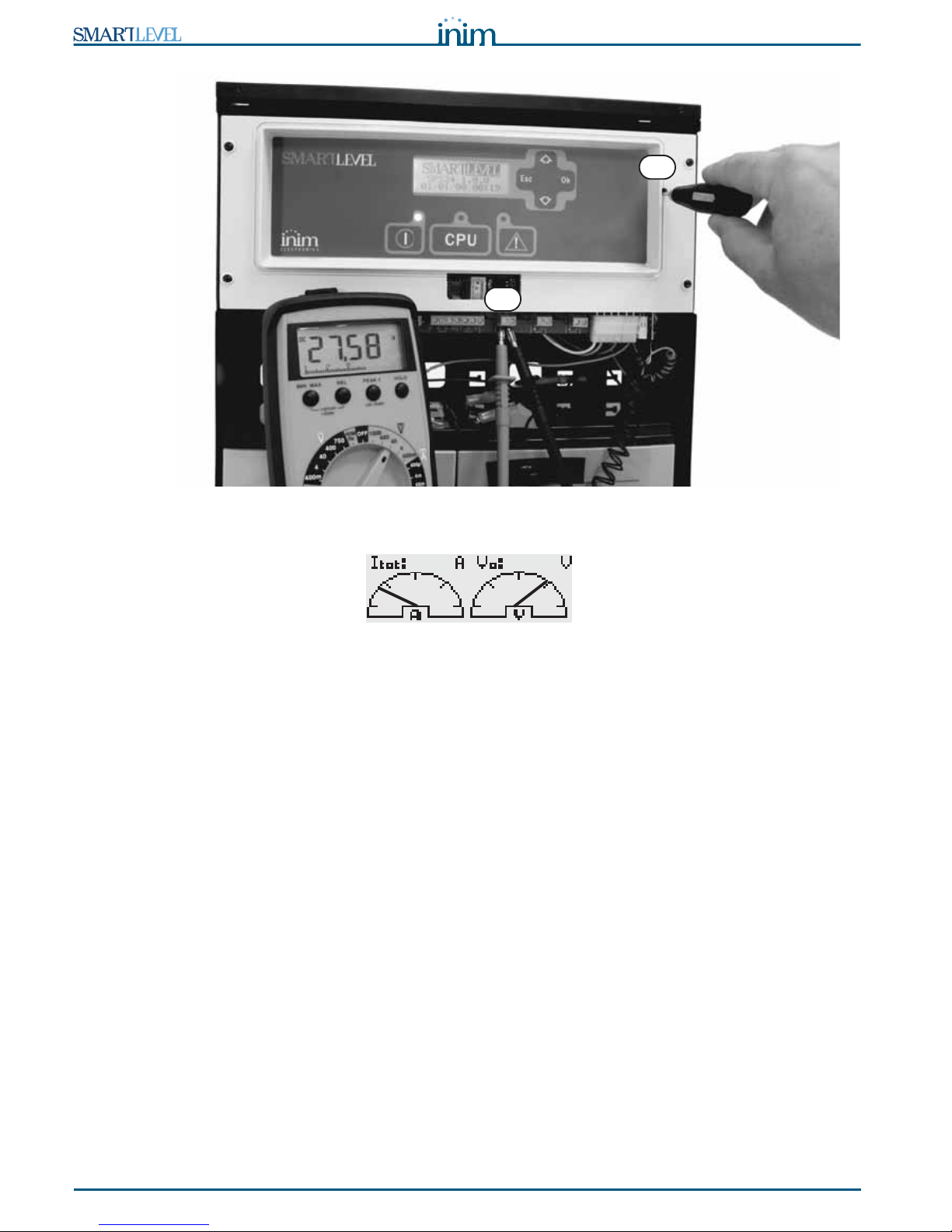
7. Using the graph (refer to paragraph 9.2 Output status screen), or a tester on OUT [B], measure the
voltage. If the voltage is incorrect, use the trimmer [C] to adjust it to the correct value.
25,5
26
26,5
27
27,5
28
28,5
29
0 5 10 15 20 25 30 35 40 45 50
°C
Volt
Page 22
22 Installation instructions
Installation and Programming manual
Figure 14 - Charge voltage adjustment using a tester
Figure 15 - Charge voltage adjustment from the station using the graphic tester
B
A
27.6
1.0
Page 23

Installation and Programming manual
Powering up the system 23
Chapter 8
Powering up the system
1. Connect the batteries.
The green ON LED will light to indicate that the power supply station is operative.
The CPU LED will blink to indicate that the board is stabilizing.
2. The power supply station will start working after several seconds and the display will show the
Language selection screen.
Figure 16 - Selecting the language
The CPU LED goes Off.
3. Power up the power supply station from the mains.
If the power supply station is not powered up within two minutes, the display will show the “
Mains
fail.” message and the FAULT LED will go On solid. When the fault clears, the LED will blink to indi-
cate that the fault has been saved to the memory.
4. Check for the presence of faults. If the fault persists, check all wiring sections thoroughly (refer to
Chapter 11 - Troubleshooting).
5. Clear all fault events.
6. Access the main menu (refer to Chapter 9 - Viewing the display screens) and, using the scroll keys,
select “
Reset station” and press Ok.
7. After reset operations, all the LEDs should go OFF, with the exception of the green ON LED.
8. The display will show the presentation screen.
Figure 17 - Presentation screen
9. Press Ok to view the Main menu. Using the scroll key T , select the “
Test LEDs” option from the
menu. Press and hold Ok and ensure that all the LEDs go On.
Select language
Ok to confirm
SPS24 1.0.0
11/11/11 08:08
Page 24

24 Viewing the display screens
Installation and Programming manual
Chapter 9
Viewing the display screens
You can navigate on the display screens using keys S, T, Ok and Esc.
Figure 18 - Navigating on the display screens
9.1 Presentation screen
This screen will appear on first powerup and after every reset operation. It shows the model, firmware
version and date and time.
9.2 Output status screen
A series of screens will indicate the status of outputs OUT1, OUT2 and OUT3.
• Electrical-current value: indicates the realtime electrical-current value of each output.
• Electrical-current and voltage values: indicates the total realtime electrical-current value of the
outputs (the sum of the electrical currents of the 3 outputs) and the realtime voltage on the outputs.
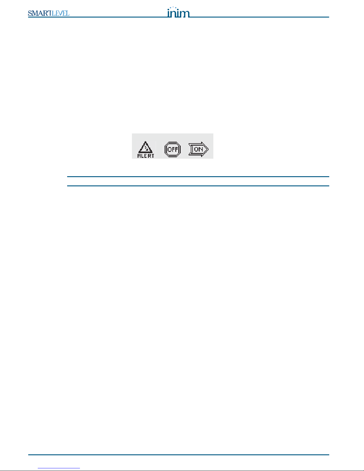
• Output status: indicates the ON, OFF or Alert status (protection active) of each output.
Output status Description
ON 24V across the terminals
OFF 0V across the terminals
ALERT The channel is protected
Presentation screen
SPS24 1.0.0
08/08/08 08:08
0.9A 0.5A 1.2A
28.0
Fault 01/11
Batt.discon.
Output status screen
2.6
OUT1 OUT2 OUT3
Faults screen
Log
LED test
Reset
Main menu
Page 25

Installation and Programming manual
Viewing the display screens 25
9.3 Main menu
This menu will allow you to carry out programming/maintenance operations and view the Events log.
9.3.1 Testing the LEDs and buzzer
From station: Ok, LED test, Ok
The 3 LEDs on the panel will go On and the buzzer will emit an audible signal for the whole time the Ok
button is pressed.
9.3.2 Viewing the events log
From station: Ok, Log, Ok
All the recorded events (maximum 100) are arranged in chronological order. Use keys S and T to scroll the
list.
The log records the following events:
• Reset events (reset power supply station)
• Reset factory settings (restore to default)
• Output status
• Activation/Restoral of all faults events
9.3.3 Resetting the power supply station
From station: Ok, Reset, Ok
The power supply station will reset when you press Ok.
Note: The successive options on the Main menu are available only when the PROG jumper is inserted.
9.3.4 Maintenance
From station: Ok, Maintenance, Ok
This option will allow you to access the maintenance section (refer to paragraph 10.1 Programming
operations).
9.3.5 Programming
From station: Ok, Programming, Ok
This option will allow you to access the settings section (refer to paragraph 10.2 Direct Maintenance).
9.4 Faults screen
This screen lists the current fault conditions of the power supply station (refer to Chapter 11 Troubleshooting).
This screen is active only when fault conditions are present.
Page 26

26 Programming and maintenance from the panel
Installation and Programming manual
Chapter 10
Programming and maintenance from the panel
This chapter describes the device configuration procedure.
Access to the programming and maintenance sections is allowed only when the PROG jumper is inserted:
1. Remove the frontplate
2. Insert the PROG jumper.
3. The Main menu provides the “
Maintenance” and “Programming”
sections.
While this status is active, the power supply station will be unable to
signal faults.
10.1 Programming operations
From station: Ok, Programming, Ok
This sequence will access the programming menu.
10.1.1 Setting up the Booster parameters
From station: Ok, Programming, Ok, Booster, Ok
This section will allow you to setup the parameters relating to output channel control.
At default all the outputs are set as “Standby-ON” with an undefined activation time (“--m --s”).
10.1.2 Power supply unit options
From station: Ok, Programming, Ok, Options, Ok
Navigate through the programming fields and set the new values.
Standby status This programming field will allow you to select the standby status of the output (24V or 0V).
Press Ok to select the activation method, then press Esc to save the setting and exit.
Standby-ON When the output is in standby status (refer to the table in paragraph 4.1
Controlling the Outputs) it will be at 24V (activation value = 0V).
Standby-OFF When the output is in standby status (refer to the table in paragraph 4.1
Controlling the Outputs) it will be at 0V (activation value = 24V).
Activation
Time.
Using keys S and T this programming field will allow you to select an output and define its
activation time (duration).
The maximum time is 20 minutes. You can increase the value in steps of 5 seconds using the
Ok key. Press Esc to save the setting and exit.
Note: The PROG jumper must be inserted during the entire programming phase.
Mains failure
delay (Delay
mainsFail.)
This is a programmable delay (0 to 30 minutes) which runs between the start of the mains failure
event and the actual fault signal. This delay avoids unnecessary signaling of brief 'Mains failure'
events.
Default setting 2 minutes.
Use the Ok key to increase this value. Esc to confirm.
Format You can choose the screen date format. Using keys S and T, select the desired format then
press Ok to save the setting and exit.
At default the format is dd/mm/yy.
Language This programming field will allow you to select the desired language. The screen will appear
automatically on first startup, that is, if the language has not already been selected.
Using keys S and T, .select the desired language the press Ok to save the setting and exit.
LED test
Reset
Maintenance
Programming
Page 27

Installation and Programming manual
Programming and maintenance from the panel 27
10.1.3 Addressing the power supply station on the RS485 BUS
From station: Ok, Programming, Ok, Address RS485, Ok
This programming section will allow you to assign addresses to all the power-supply stations on the RS485
BUS of the INIM fire detection panel.
Select an address from 01 a 16 (the default address is 01). If more than one SmartLevel power supply
station is connected to the RS485 BUS, each must have a different address.
Press Ok to assign the desired address. Press Esc to save the setting and exit.
10.1.4 Reset default (factory settings)
From station: Ok, Programming, Ok, Default data, Ok
If you select this option, you will be asked to confirm the operation. If you press OK, all the settings will
reset to default (factory settings).
10.2 Direct Maintenance
From station: Ok, Maintenance, Ok
This section will allow you to carry out software maintenance using the power supply station interface.
10.2.1 Time and Date
From station: Ok, Maintenance, Ok, Time and date, Ok
Using keys S and T, select the desired field then press Ok to modify the value.
Press Esc to save the setting and exit.
10.2.2 Booster ON/OFF
From station: Ok, Maintenance, Ok, Booster ON/OFF, Ok
This section will allow you to modify the output channels directly and view the status of the circuit
breakers. Using keys S and T, select the desired output then adjust it to requirements using the Ok key.
If the selected output is set as
ON, it will have a value of 24V. If the selected output is set as OFF it will
have a value 0V.
If the
In prot. string appears, it means that the corresponding protection circuit has switched the output
Off due to either short-circuit or overload (a charge that exceeds specifications). Under these
circumstances, follow the procedure described in paragraph 11.2 “Output protection” fault.
10.3 Closing a Programming/Maintenance session
Once all operations are complete, remove the PROG. jumper to end the programming session.
The power supply station will be fully operative and the display will show the presentation screen.
Parameter Default value
Mains failure delay 2 minutes
Output activation time (ON Time) Undefined
Standby status of the outputs 24V
Power Supply unit address on the RS485 BUS 01
Language You must select the language at
first startup
Page 28

28 Troubleshooting
Installation and Programming manual
Chapter 11
Troubleshooting
Attention: Only authorized operators Level 3 may rectify faults.
11.1 Current faults list
If faults occur, the power-supply station will provide the fault details on the display.
The first line on the screen shows the chronological order number of
the fault over the total number of active faults (the example shows the
first of six faults). The line below indicates the type of fault concerned.
Keys S and T will allow you to scroll the faults list.
To access the faults list from the presentation or status screen pressing Esc. To exit the faults list and step
back to the presentation or status screen press Ok.
Note: The list is not available when there are no fault conditions to report.
11.2 “Output protection” fault
This occurs when the power supply station forces the outputs to OFF
status (0V) as a means of protection.
Protection status can be triggered by short-circuit or overload (a
charge that exceeds specifications) on the output concerned.
There are two ways of restoring this fault, as follows.
• From the Maintenance menu
1. Insert the PROG Jumper.
2. From station: Ok, Maintenance, Ok, Booster ON/OFF, Ok
the power supply station will reset the Fault LED and the Fault relay.
3. Set the protected output to OFF.
4. Clear the fault on the output circuit in question.
5. Set the protected output to ON and wait until the power supply station restores the output
automatically. If the condition persists for more than 10-15 seconds, repeat the operation.
6. When the fault restores, exit the Maintenance menu (remove the PROG jumper).
• Using control inputs
1. Using the inputs (which control the outputs), force the output to OFF (0V) status in order to protect the
circuit. In this way, the Fault LED and the Fault relay will remain active.
2. Clear the fault on the output circuit.
3. Re-activate the output via the respective input, or carry out a reset operation (From the station: Ok,
Reset, Ok). Wait until the power supply station restores the protection status automatically. If the
condition persists for more than 10-15 seconds, repeat the operation.
4. When the fault restores, the Fault LED will start to blink to indicate that the fault details have been
saved to the memory. To stop the LED from blinking, reset the power-supply station. Re-activation via
reset (refer to point 3.) is unnecessary.
Fault 01/06
Batt.discon.
Fault 01/01
Protec. OUT1
OUT1 OUT2 OUT3
Page 29

Installation and Programming manual
Troubleshooting 29
11.3 Battery Faults
11.3.1 Battery Disconnected or Inefficient
The battery is not connected (“Batt.discon.”) or has failed the
battery efficiency test (“
Batt.inef.”) (EN 54-4:1997 A2).
1. Allow the batteries to charge for several hours.
2. If the fault signal persists, disconnect the batteries from the panel and test them separately.
3. If just one of the batteries has a voltage below 12.5 - 13 V:
• Replace the faulty battery only.
• Allow the batteries to charge for several hours.
• Ensure that the fault has cleared.
4. If both batteries are @12.5 - 13 V, it means both batteries are inefficient (even though the voltage
without load is correct).
• Replace both batteries.
• Allow the batteries to charge for several hours.
• Ensure that the fault has cleared.
• With the batteries disconnected, ensure that the voltage on the battery connector ([B] in Figure 14 -
Charge voltage adjustment using a tester) on the power supply station is:
-27.6 V if the battery is not equipped with a thermal probe or,
-the value indicated in the graph Figure 13 - Charge voltage in accordance with the Battery
temperature, if the battery is equipped with a thermal probe.
• If the value is incorrect, use the trimmer ([C] in Figure 14 - Charge voltage adjustment using a tester)
to adjust it.
11.3.2 Low Battery
The batteries are running low.
This signal should be present only during primary power source failure
(Mains 230 Vac). Mains power must be restored in order to charge the
batteries.
11.3.3 Overload/Underload
The batteries have been improperly charged (the charge voltage does
not comply with product specifications (“
Underload.” or
“
Overload.”).
The power supply station triggers this signal when the primary power
source (mains) is present but the battery charge is insufficient. If this
occurs, check the output voltage of the power supply station and
adjust the battery-charge voltage.
11.4 Other faults
The display shows the message: Meaning
Mains fail.
Primary power failure (230 Vac).
Ground fault
Voltage dispersion to earth has been detected.
Fault 01/01
Batt.inef.
Fault 01/01
Low Batt.
Fault 01/01
Underload
Page 30

30 Maintenance
Installation and Programming manual
Appendix A
Maintenance
The following operations must be carried out regularly.
1. Using a damp lint-free cloth, remove any dust that may have gathered on the control panel (do not use
any kind of cleaning product or solvent!).
2. From station, press Ok, LED test, Ok to check the proper operating capability of the LEDs and buzzer.
3. Check the battery efficiency and change them if necessary.
4. Check the integrity of all wires and connections.
5. Ensure that there are no extraneous objects inside the control panel.
Note: Points 1 and 2 can be carried out by the users, however, all other points must be carried out by
qualified technicians only.
Page 31

Installation and Programming manual
Order codes 31
Appendix B
Order codes
Following are the order codes of INIM Electronics s.r.l. products:
Code Description
SPS24040 1.4A - 27.6V SmartLevel power supply station in metal enclosure with user
interface
SPS24140 4A - 27.6V SmartLevel power supply station in metal enclosure with user
interface
BPS24040 1.4A - 27.6V Switching power-supply module in metal enclosure with housing
for 2 x 7Ah, 12V batteries
BPS24140 4A - 27.6V Switching power-supply module in metal enclosure with housing for
2 x 17Ah, 12V batteries
IPS24040 1.4A - 27.6V Switching power-supply module
IPS24140 4A - 27.6V Switching power-supply module
DCMIINIESPS24 Installation and Programming Guide for SmartLevel power-supply units
ProbeTH Thermal probe for battery charge optimization
Page 32

32 Order codes
Installation and Programming manual
 Loading...