


Installation and User manual
EN 54-2
EN 54-4
EN 54-21
0051
0051-CPR-1754
F-COM
Telephone communicator
Installation and User manual
DCMIINIEFCOM-100-20190716
1

Telephone communicator
INIM Electronics s.r.l. (Seller, Our, Us) warrants the original purchaser that this
product shall be free from defects in materials and workmanship under normal
use for a period of 24 months. As INIM Electronics s.r.l. does not install this
product directly, and due to the possibility that it may be used with other
equipment not approved by Us; INIM Electronics s.r.l. does not warrant against
loss of quality, degradation of performance of this product or actual damage that
results from the use of products, parts or other replaceable items (such as
consumables) that are neither made nor recommended by INIM Electronics. Seller
obligation and liability under this warranty is expressly limited to repairing or
replacing, at Seller's option, any product not meeting the specifications. In no
event shall INIM Electronics s.r.l. be liable to the purchaser or any oth er person for
any loss or damage whether direct or indirect or consequential or incidental,
including without limitation, any damages for lost profits, stolen goods, or claims
by any other party caused by defective products or otherwise arising from the
incorrect or otherwise improper installation or use of this product.
This warranty applies only to defects in parts and workmanship relating to normal
use. It does not cover:
• damage arising from improper maintenance or negligence
• damage caused by fire, flood, wind or lightning
•vandalism
• fair wear and tear
INIM Electronics s.r.l. shall, at its option, repair or replace any defective products.
Improper use, that is, use for purposes other than those mention ed in this man ual
will void the warranty. Contact Our authorized dealer, or visit our website for
further information regarding this warranty.
INIM Electronics s.r.l. shall not be liable to the purchaser or any other person for
damage arising from improper storage, handling or use of this product.
Installation of this Product must be carried o ut by qualified pers ons appointed by
INIM Electronics. Installation of this Product must be carried out in accordance
with Our instructions in the product manual.
The information contained in this document is the sole property of INIM
Electronics s.r.l. No part may be copied without written authorization from INIM
Electronics s.r.l.
All rights reserved.
Warranty
Limited
warranty
Copyright
2

Installation and User manual
Table of
contents
Warranty . . . . . . . . . . . . . . . . . . . . . . . . . . . . . . . . . . . . 2
Limited warranty. . . . . . . . . . . . . . . . . . . . . . . . . . . . . . . 2
Copyright . . . . . . . . . . . . . . . . . . . . . . . . . . . . . . . . . . . . 2
Table of contents . . . . . . . . . . . . . . . . . . . . . . . . . . . . . . 3
Chapter 1 General information. . . . . . . . . . . . . . . . . . . . . . . . . . . . . 5
1-1 Manufacturer's details . . . . . . . . . . . . . . . . . . . . . . . . . . . . . . . . . . . . . 5
1-2 About this manual . . . . . . . . . . . . . . . . . . . . . . . . . . . . . . . . . . . . . . . 5
1-3 Included documents . . . . . . . . . . . . . . . . . . . . . . . . . . . . . . . . . . . . . . 5
Chapter 2 Device description. . . . . . . . . . . . . . . . . . . . . . . . . . . . . . 6
2-1 Unpacking the box . . . . . . . . . . . . . . . . . . . . . . . . . . . . . . . . . . . . . . . 6
2-2 Technical description . . . . . . . . . . . . . . . . . . . . . . . . . . . . . . . . . . . . . 7
2-3 CE Mark . . . . . . . . . . . . . . . . . . . . . . . . . . . . . . . . . . . . . . . . . . . . . . 9
Chapter 3 Installation . . . . . . . . . . . . . . . . . . . . . . . . . . . . . . . . . . . 10
3-1 Wall-mounting . . . . . . . . . . . . . . . . . . . . . . . . . . . . . . . . . . . . . . . . . . 10
3-2 Connecting the switching power supply. . . . . . . . . . . . . . . . . . . . . . . . . 10
3-3 Mounting the Antenna . . . . . . . . . . . . . . . . . . . . . . . . . . . . . . . . . . . . 12
3-4 Telephone connections . . . . . . . . . . . . . . . . . . . . . . . . . . . . . . . . . . . . 12
3-5 Connecting to a PC. . . . . . . . . . . . . . . . . . . . . . . . . . . . . . . . . . . . . . . 13
3-6 Connecting the terminals . . . . . . . . . . . . . . . . . . . . . . . . . . . . . . . . . . 1 3
Chapter 4 First startup . . . . . . . . . . . . . . . . . . . . . . . . . . . . . . . . . . 18
4-1 Guided programming (initial setup wizard) . . . . . . . . . . . . . . . . . . . . . . 18
Chapter 5 Using the communicator . . . . . . . . . . . . . . . . . . . . . . . . . 20
5-1 Users . . . . . . . . . . . . . . . . . . . . . . . . . . . . . . . . . . . . . . . . . . . . . . . . 20
5-2 User interface . . . . . . . . . . . . . . . . . . . . . . . . . . . . . . . . . . . . . . . . . . 20
5-3 Language used by the user interface . . . . . . . . . . . . . . . . . . . . . . . . . . 22
5-4 Signals on the display. . . . . . . . . . . . . . . . . . . . . . . . . . . . . . . . . . . . . 23
5-5 Main menu . . . . . . . . . . . . . . . . . . . . . . . . . . . . . . . . . . . . . . . . . . . . 24
Appendix A Events . . . . . . . . . . . . . . . . . . . . . . . . . . . . . . . . . . . . . . 25
Appendix B Simplified declaration of conformity. . . . . . . . . . . . . . . . . . 28
WEEE. . . . . . . . . . . . . . . . . . . . . . . . . . . . . . . . . . . . . . . 31
3

Telephone communicator
4

Installation and User manual
GENERAL INFORMATION
Manufacturer: INIM Electronics s.r.l.
Production plant: Centobuchi, via Dei Lavoratori 10
Comune: 63076, Monteprandone (AP), Italy
Tel.: +39 0735 705007
Fax: +39 0735 704912
e-mail: info@inim.biz
Web: www.inim.biz
The persons authorized by the manufacturer to repair or replace the parts of this
system have authorization to work on INIM Electronics brand devices only.
Manual code: DCMIINIEFCOM
Revision: 1.00
• Installation and User manual (this manual)
• Programming manual
The manuals are supplied with the apparatus and can be downloaded from the
“Download” section of the Website: www.inim.biz. The installation manual is
included in the package. To order further copies contact the offices at INIM
Electronics.
Chapter 1
1-1Manufacturer's details
1-2About this manual
1-3Included documents
General information 5

DEVICE DESCRIPTION
The F-COM is a universal autonomous telephone communicator, certified in
accordance with EN 54-21 and EN 54-4 standards. It is to be used with fire
detection control panels manufactured both by Inim Electronics and other
manufacturers.
It is capable of operating as:
• fire alarm transmission device (device E for EN 54-1)
• fault signal transmission device (device J for EN 54-1)
The communicator operates autonomously:
• It detects control panel alarm and fault events through input terminals, as
well as its own internal events.
In Appendix A you can find the complete list of events generated.
• Activates programmable outputs.
• Makes voice calls over the PSTN line or GSM mobile network.
The default voice messages can be replaced by recorded custom messages.
• Sends digital messages using Con tact ID pr otoco l (over the PST N line o r GSM
mobile network) and SIA-IP (over mobile data network).
• Sends SMS messages over GSM network.
The default messages can be replaced by custom text messages.
• Provides communication feedback through the ALARM ACK output terminal
and LED signals.
Telephone communicator
Chapter 2
INIM does not ensure full availability of all the GSM functions described in this
manual for the various combinations of GSM service provider, SIM type and
telephone set used.
ATTENTION!
2-1Unpacking the box
The device is packed in a cardboard box which contains:
• The F-COM inside its metal enclosure
• A bag containing the installation kit comprising:
- 3 x 3k9 Ohm 1/4W resistors
- 5 x 100 Ohm 1/4W resistors
- 1 x 1500 Ohm 1/4 W resistor
-1 jumper
- battery connection wires
-thermal probe
- ring terminal for the connection to Ground
•Antenna
• Installation manual (this manual)
The installation kit does not include:
• 12V 1.3A/h batteries
•SIM Card
Be sure to have these items on hand before starting the installation procedure.
6 Device description
Note

Installation and User manual
A2
A2
A2
A2
A2
A2
A2
A2
A2
A2
A2
A2
A2
A2
A2
A2
2-2Technical description
O
P
Q
A2
E
F
A2
A
B
C
A2
D
G
A2
H
A2
I
O
A2
P
Q
J
K
A2
O
A2
L
F
M
A2
N
A2
R
Q
P
A
B
C
D
E
F
G
RESET button to restart the communicator
H
FACTORY button to restore factory settings
I
Signalling LEDs
Display
Navigation buttons
USB Port
SIM card connector
Antenna connector
Terminal board
Table 1: Description of parts
J
K
L
M
N
O
P
Q
R
Power supply
Mains power terminals
Ground connection point
Battery terminals
Thermal probe
Cable entry hole
Frontplate anchor hole
Backplate anchor hole
Battery housing
Device description 7
Q
P

Telephone communicator
N
230V ~ 50/60 Hz
AC I
nput
Table 2: Terminal board
n. icon/identifier function
1
2, 3 L.E.
4, 5 L.I.
6ALARM ACK
7OUT1
8FAULT
9, 13 -
10, 11, 12 IOx
14, 15 ALARM CALL
16, 17 FAULT CALL
Table 3: Technical specifications
Supply voltage
Maximum absorption from the 230V line
AC mains input terminals
Telephone line connection terminals
Output terminal for confirmation of receipt of an alarm
Programmable output terminal (by default it activates in
Output terminal that activates in the presence of
Programmable input/output terminals
Input terminal for the activation of alarm communications
Input terminal for the activation of fault communications
Ground terminal
Internal telephone line terminals
communication
the event of a connection fault)
communicator faults
Ground reference
230V~ (-15% + +10%)
50/60Hz
0.5A
Nominal output voltage
Maximum current supplied by
the power-supply module
Main board current absorption
Battery specifications
Minimum flammability class of casing
Maximum internal resistance of battery (R
Battery shutdown tension
Internal fuse of power supply module
Maximum output current ripple
Operating temperature
Enclosure protection class (EN 60529)
Classification in accordance with EN 54-21
Dimensions (H x W x D)
Weight (without batteries)
8 Device description
for external loads and main board
Output voltage
Insulation class
total
for battery charging
during standby
during alarm
)
i max
27.6V
2.1A
0.6A
1.5A
50mA
150mA
2 x 12V / 1.3Ah
UL94-V2
2.7Ohm
19 / 27.6V
19V
T 3.15A 250V
1%
from -5°C to 40°C
I
IP30
Type 2
260 x 200 x 55mm
1500g

Installation and User manual
2-3CE Mark
,1,0(OHFWURQLFVVUO
9LD'HL/DYRUDWRUL)UD]&HQWREXFKL
0RQWHSUDQGRQH$3,WDO\
&35
(1$$
(1
)&20
Alarm transmission and fault warning routing equipment with embedded
power supply equipment for use with fire detection and fire alarm systems
3RZHUVXSSO\SHUIRUPDQFH
7UDQVPLVVLRQSHUIRUPDQFH
2SHUDWLQJUHOLDELOLW\
'XUDELOLW\RI
RSHUDWLQJUHOLDELOLW\
)RUWKHLQIRUPDWLRQUHTXLUHGE\SRLQWVHHGDWDFRQWDLQHGLQWKLV
PDQXDO
)RUWKHLQIRUPDWLRQUHTXLUHGE\SRLQWVHHGDWDFRQWDLQHGLQWKLV
PDQXDO
$GGLWLRQDOLQIRUPDWLRQDFFRUGLQJWR(1
installed in buildings
(VVHQWLDOIHDWXUHV
7KHUPDOUHVLVWDQFH
9LEUDWLRQUHVLVWDQFH
+XPLGLW\UHVLVWDQFH
(OHFWULFDOVWDELOLW\
$GGLWLRQDOLQIRUPDWLRQDFFRUGLQJWR(1
3HUIRUPDQFH
3$66
3$66
3$66
3$66
3$66
3$66
3$66
Device description 9

INSTALLATION
The installation must be carried out in full compliance with local fire regulations,
with the laws and provisions in force, and in accordance with the relative
instructions and guidelines.
The communicator should be located in a place that is:
•Dry
• Away from electromagnetic interference (electrical equipment, heating units,
air-conditioning units, radio transmitters, etc.) and metal objects.
Check that the GSM network signal of the selected provider is adequate.
1. Remove the securing screws and frontplate (table 1, P).
2. Using the back of the enclosure (table 1, Q), mark the anchor screw locations on the wall. Be sure not to drill in the vicinity of electrical wiring or
plumbing/gas pipes, etc.
3. Insert the screw anchors (recommended size 6mm).
4. Pull the connection wires through the wire entry (table 1, O).
5. Using the respective screws, attach the box to the wall.
6. Complete the connections with the terminals.
7. Replace the frontplate.
Telephone communicator
Chapter 3
3-1Wall-mounting
ATTENTION!
power supply
3-2Connecting the switching
The F-COM must be powered via the 230V~ mains power supply, with necessary
use of the two backup batteries.
3-2-1Mains power 230V~
For the power supply from the network, it is necessary to provide a separate line
deriving from the electrical distribution panel. The line must be protected by a
safety-standards compliant circuit breake r (trip switch).
The Grounding system of the site must be made in accordance with the current
regulations in force.
Use extreme caution when connecting to the primary power source. Danger of
electric shock.
10 Installation
ATTENTION!

Installation and User manual
A2
A2
A2
A2
A2
A2
A2
A2
A2
A2
A2
A2
A2A2
A2A2
E
+
-
+
-
A
B
G
C
D
F
I
H
J
K
1. Connect the mains power supply to the terminals on the power-supply
module ([A],table 1, K).
For a safety standards compliant system, the Line must be connected to terminal
“L” and the Neutral conductor to terminal “N”.
The power supply must come directly from an electrical distribution panel via a
reserved line. This line must be protected by a suitable sectioning device as
required by the local standards and laws in force.
The electrical system of the building must have a magneto-thermal switch as an
additional protection against overcurrents and short circuits.
The end of a stranded wire must not be consolidated with soft soldering in points
where the wire is subjected to contact pressure.
2. Crimp the earth line wire to the eyelet terminal [B].
3. Secure the wire with the eyelet to the control panel using the ground connection screw [C].
4. Ensure that the terminal “ ” of the power supply module [D]], the main
board [E] and the frontplate [F] are connected to Ground.
The earthing system must comply with current regulations regarding electrical
safety in the systems.
A protective earth connection ensures that all exposed conductive surfaces are at
the same electrical potential as the earth surface, in order to avoid the risk of
electrical shock when a person touches a device in which an insulation fault has
occurred. In the event of an insulation fault, a protective earth connection will
generate a high fault current which in turn will trigger an overcurrent protection
device (fuse) and disconnect the power supply.
5. Ensure that low-current safety or signal lines DO NOT come into contact
with points with potentially dangerous currents.
Using a plastic cable tie, bunch the wires together and secure them to one
of the wire hooks on the backplate of the enclosure [G].
The connection wires (to the mains supply and also any other wires inside the
cabinet) must be secured to the cable hooks on the backplate by means of plastic
cable ties. Use cable with double isolation for the connection to the electrical
mains.
Note
ATTENTION!
Installation 11

Telephone communicator
an INIM control panel, it is necessary to insert the E-FAULT jumper of the power
supply.
The metal enclosure of the communicator is capable of housing two 12V 1.3Ah
lead batteries. The two batteries must be connected in series, in such a way as to
supply 24V.
1. Place the batteries into the battery compartment inside the enclosure ( table
1, R).
2. Using the battery wire ([H]), connect the batteries together.
3. Connect the wire coming from the power supply ([I] table 1, M) to the battery terminals ([D]).
Ensure that the polarity is correct.
Red - positive
Black - negative
The connection of the batteries before the mains voltage is present will not
activate the system. Once the mains voltage is supplied, the p ower-sup ply modul e
will connect the batteries automatically and initialize the circuits which manage
them.
4. Position the thermal probe ([K], table 1, N). The thermal probe must be
positioned on the side of the battery and held in place by a strip of tape.
The lead batteries provide the secondary power source that will power the F-COM
and the devices connected to its outputs when the primary power source is not
present.
1. Remove the antenna from the bag.
2. From above the enclosure, insert the antenna cable into its appropriate
placement (table 1, O).
3. Fit the antenna in the placement adapted for network reception using the
magnetic base or by attaching it to the wall by means of the two anchor
screws.
4. Using the ancillary wire, connect the antenna wire to appropriate connector
on the main board (table 1, F).
EN54To satisfy EN 54 standard requirements, when the communicator is not used with
3-2-2Connecting the batteries
ATTENTION!
3-3Mounting the Antenna
3-4Telephone connections
Connect the PSTN line (Public Switched Telephone Network) to the “L.E.”
terminals. (2 and 3, tabella 2 "Terminal board").
The F-COM is protected against damage caused by lightening strikes.
Connect any telephone apparatus to the “L.I.” terminals. (4 and 5).
43215
L.E. L.I.
12 Installation
Note

Installation and User manual
INPUT
3900Ohm
orange,
white, red
100Ohm
brown,
black, brown
ALARM/FAULT CALL
supervised
INPUT
ALARM/FAULT CALL
non-supervised
It is necessary to connect to a PC equipped with the F-COM-STUDIO software for
the programming, layout and monitoring of the system the F-COM is connected to.
The connection with the PC can be achieved through a USB cable inserted into the
appropriate connector on the main board (table 1, D).
Once the F-COM is connected, the driver for the installation of the USB device
recognized by the PC is available in the F-COM-STUDIO software installation
folder, specifically in the following folder (in the case of a default installation):
C:\Program Files\F-COM-STUDIO\drivers\
Use shielded cable with the necessary number of cond uctors
Proper section (minimum 0.5mm², maximum 2.5 mm²)
Compliant with local standards and laws in force
3-5Connecting to a PC
3-6Connecting the terminals
EN54For the connection of the input/output terminals use:
connection
The “ALARM CALL” and “FAULT CALL” inputs are to be used for the start
communication signals relating to fire alarms and control panel faults.
These inputs can be supervised by connecting the appropriate balancing
resistance, and are compatible with the communicator output on Inim fire
detection panels.
The illustrated resistance values (3900 and 100Ohm) are thos e r equired when the
default input threshold values are used.
Since thresholds are programmable via the software, the installer can choose the
balancing resistance values.
When supervision is enabled, the occurrence of open and short-circuit conditions
will generate an “Interconnection fault”.
Following is the connection of the communicator with a SmartLine fire-detection
control panel manufactured by Inim Electronics, for alarm and fault
communications:
3-6-1ALARM CALL and FAULT CALL
Installation 13

For SmartLine control panels it is necessary to enable the “O utput to faul t w arning
FAULT
CALL
RELAY
NONC
C
ZONE 4
I/O
AUX R
1500Ohm
brown,
green, red
100Ohm
brown, black,
brown
SmartLine
F-COM
ALARM
CALL
DIALER
SmartLine
F-COM
3900Ohm
orange,
white, red
Load
External
power
supply 30V=
max
routing equipment” option using SmartLeague software, above version 3.5.1.6.
•Polarity:
- Normally Open (default)
-Normally Closed
•Supervision:
- Enable (default)
-Disabled
• Programmable thresholds
The “FAULT CALL” terminal is a J function input for the signalling of faults.
If you desire to maintain an EN54-21 standard compliant system, DO NOT disable
terminal supervision.
The voltage applied to the “ALARM CALL” and “FAULT CALL” terminals must be
between 0 to 3.3V=.
Telephone communicator
PROGRAMMING
OPTIONS
EN54The “ALARM CALL” terminal is an E function input for the signalling of alarms.
and OUT1 terminals
3-6-2Connecting ALARM ACK, FAULT
The three outputs, “ALARM ACK”, “FAULT” and “OUT1” are open-collector outputs
capable of driving maximum 150mA / 30V=.
The following wiring diagram illustrates connections for the activation of a load
when an output closes to ground.
OUTPUT
14 Installation

Installation and User manual
The outputs can be supervised.
The “Interconnection fault” is activated in the event of:
• open-collector output open, if the load to positive is not detected or when a
short-circuit to ground is detected
• open-collector output closed, in the event of an internal fault
Table 4: Output functions
terminal activation deactivation
Activates each time an alarm communication is
ALARM ACK
Activates in the eve nt of one or more faults:
FAULT
Activates in response to the events confi gured for
OUT1
•Polarity
- Normally Open (default for “ALARM ACK” and “OUT1”)
- Normally Closed (default for “FAULT”)
•Supervision
- Enabled
- Disabled (default)
• Monostable/Bistable
• Monostable duration
“ALARM ACK” and “FAULT” cannot be programmed as monostable; “OUT1” is
bistable at default.
At default it activates when the “Interconnection
confirmed from remote:
- in the case of a voice call when the
*
” key is pressed on the telephone in
“
use
- in the case of a digital communication,
on reception of the “ACK” signal
- interconnection fault
- battery fault
-no battery
- power supply fault
- mains failure
- ground fault
- programming fault
-PSTN fault
- SIM fault
- insufficient SIM credit
- mobile network fault (GSM)
- mobile network data fault
this output (refer to Appendix A).
fault” occurs.
If configured as bistable, this output is restored
when the communicato r is rea rm e d.
If configured as bistable, the output will restore
At default it restores when the “Intercon nection
when all the faults restore.
It restores when the event configured for this
output restores (refer to Appendix A).
fault” restores.
PROGRAMMING
OPTIONS
3-6-3Connecting IOx terminals as
inputs
The three terminals, “IO1”, “IO2” and “IO3” are configured as inputs at default.
These terminals can be supervised by connecting the appropriate balancing
resistances. The illustrated resistance values (3900 and 100Ohm) are those
required when the default input threshold values are used.
Since thresholds are programmable via the software, the installer can choose the
balancing resistance values.
Installation 15

Telephone communicator
INPUT
INPUT
Terminal IOx
non supervised
3K9Ohm
orange,
white, red
When supervision is enabled, the occurrence of open and short-circuit conditions
will generate an “Interconnection fault”.
Each "IOx" terminal has an internal resistor, a "pull-up" resistor, which allows to
change the contact reference (to ground or positive) according to the
programming.
Therefore, there are 4 ways of connecting a contact to an IOx input:
• normally-closed contact referred to ground (negative removed)
• normally-open contact referred to ground (negative applied)
• normally-closed contact referred to positive (positive removed)
• normally-open contact referred to positive (positive applied)
It is possible to associate one of the functions in the following table to each input:
function input activated note
Stop alarm communications
Stop fault communications
Stop other types of communications
(generic or supervision)
Disable alarm communications
Disable fault communications
Disable other communication types
(generic or monitoring)
Force call to cellular channe l
Force calls to PSTN
Rearm
Table 5: IOx functioning as input
If the input is activated, the specified
communication types will be cancelled
from the call queue and a n y on go ing ca lls
communication types wil l be disabled.
If the input is activated, it will force the
communicator to use the mobile network
If the input is activated, it will force the
communicator to use the PSTN line for
- terminates ongoing communications
- switches off the “ACK” LED and
- terminates audible alarm and fault
- deactivates the “ALARM ACK” output
- deactivates the programmable
will be terminated.
If the input is activated, the specified
for voice and Contact ID calls.
voice and Contact ID calls.
Activation of the input:
and cancels any communications in
the call queue
yellow blinking on the “Power” LED
(that indicates “System restart”)
signalling (on buzzer), the signalling
will restart when a new alarm or
fault signal event occurs
outputs (“OUT1”, “IOx”)
One or more communication types can
One or more communication types can
Forcing will have no effect if at the
configured as “Force calls to PSTN” is
Forcing will have no effect if at the
configured as “Force calls to cellular
restorable events w il l be co nsid e red
however, in order to allow the output
to be deactivated, it is necessary for
all the associated events to restore.
Terminal IOx
supervised
100Ohm
brown,
black, brown
CONTACT
REFERENCE
be selected.
Default for terminal “IO2”.
be selected.
Default for terminal “IO3”.
same moment another input
active.
same moment another input
channel” is active.
The monostable outputs will
deactivate unconditionally.
For Bistable outputs , the no n-
“zeroed” (refer to Appendix A),
Default for terminal “IO1”.
16 Installation

Installation and User manual
If none of the functions in the table are associated with an input, the activated
actions will be those specified by events/actions programming (refer to Appendix
A).
•Polarity:
- Normally Open contact (default)
-Normally Closed contact
•Supervision:
- Enabled
- Disabled (default)
• Contact reference
- Ground (default)
- Positive
• Programmable thresholds
When the “IOx” terminals are programmed as inputs, the voltage applied must be
between 0 and 3.3V=.
If set as an output, the “IOx” terminal operates as an open-collector output,
capable of driving maximum 150mA / 30V=.
These terminals can be programmed to activate in the presence of events as per
event/action programming (refer to Appendix A)
The outputs can be supervised.
The “Interconnection fault” is activated in the event of:
• open collector output open, if the load to positive is not detected or if a short
circuit to ground is detected)
• open-collector output closed, in the event of an internal fault
PROGRAMMING
OPTIONS
3-6-4Connecting IOx as outputs
•Polarity
-Normally Open
-Normally Closed
•Supervision
- Enabled
-Disabled
• Monostable/Bistable
• Monostable duration
PROGRAMMING
OPTIONS
Installation 17

FIRST STARTUP
To perform a correct first startup operation, work carefully through the following
steps.
During the completion of wiring, do not power the F-COM or any connected
devices, neither via mains (230V a.c.) nor battery.
1. Attach the F-COM to the wall.
2. Connect the antenna.
3. Connect the input and output terminals to the fire detection system.
4. Connect the telephone line (if required).
5. Insert the SIM card (if required).
6. Connect the primary power source (230V~).
7. Connect the backup batteries.
Start the initializing phase.
8. Follow the guided programming wizard on the screen.
(initial setup wizard)
On first startup of the communicator or restoring of factory data, the display
provides the user with a fast programming guide.
By following this guided procedure and configuri ng at least one telephone contact,
thanks to the actions programmed at default (refer to Appendix A), the F-COM will
be able to:
• make voice calls for the activation of ALARM CALL and FAULT CALL terminals;
• send SMS texts and digital communications (Contact ID, SIA-IP, IP2RX) for
the activation of ALARM CALL and FAULT CALL terminals as well as for the
activation/reset of the important internal events of the communicator.
Telephone communicator
Chapter 4
ATTENTION!
4-1Guided programming
The steps of the guided procedure are:
1. Language selection: Italian or English (default)
2. Setting the date and time
3. Configuration of phone contact n.1
4. Configuration of phone contact n.2
The configuration of the contacts initially r eq ui r es t he t yp e and , b ased on t hi s , the
parameter settings:
Table 6: Fast configuration of contacts
Contact type Required parameters
T elephone number
Voice
SMS Telephone number
18 First startup
Preferential channel (PSTN or mobile)
Supervision period

Installation and User manual
Table 6: Fast configuration of contacts
Contact ID
SIA-IP
IP2RX
T elephone number
Preferential channel (PSTN or mobile)
Account code
Supervision period
IP address
Port
Account code
Supervision period
IP address
Port
Account code
Supervision period
be enabled and the maximum period must be 24 hours.
5. Configuration of access to the mobile data network.
The last step is implemented only when the type of one of the set contacts is SIAIP or IP2RX. APN, username and password will be requested.
After entering this data the communication channel of the mobile data network
will be enabled.
EN54In order to guarantee compliance with the EN 54-21 standard, supervision must
First startup 19

Telephone communicator
Chapter 5
USING THE
COMMUNICATOR
5-1Users
The F-COM communicator manages different access levels to the device, distinct
from the system usability limitations.
Each user must have an access PIN the first digit of which characterizes the
typology and cannot be changed:
Table 7: Access levels
description permissions access mode
Access to the viewing of:
Advanced user PIN
carry out the battery test.
programming options.
Standard user
Advanced user
Installer
- diagnostic information
- fault details
-events log
The same permissions as the standard user, plus the possibility to
change some program ming options relating to the contac ts:
- telephone numbers
- communication protocol
- IP address, port, account code
The same permissions as the standard user, plus the possibility to
By means of the programming software, change all the
User PIN
Default 000000
Default 111111
Installer PIN
Default 222222
5-2User interface
F-COM inim.biz
CARRIER
20/05/2019 18:23:00
ENTER PIN: [ ]
Table 8: Signalling LEDs
Icon description activation signal
- Flashing green, indicates an ongoing
Telephone
line
20 Using the communicator
Indicates that the communicator is
engaged in an ongoing call on the
PSTN channel or the presence of a
PSTN fault.
communication on the PSTN, different from an
alarm communication.
- Flashing red, indicates an ongoing alarm
communication on the PSTN.
- Solid yellow, indicates a fault on the PSTN line
(line down on “L.E. terminals”)

Installation and User manual
Table 8: Signalling LEDs
Icon description activation signal
- Flashing green, indicates an ongoing
communication on the GSM network, different
from an alarm communication.
- Flashing red, indicates an ongoing alarm
Mobile net-
work
ACK alarm
Interconnec-
tion fault
Power-sup-
ply fault
Indicates that the communicator is
engaged in a call on the mobile
network or the presence of a mobile
Indicates a fault in the connections
Signals power-supply faults and the
network fault.
Indicates receipt or not of the
confirmation of receipt of a fire
alarm communication or a voice
with the control panel or a fault
message.
during supervision of phone
contacts.
“System restart” event.
communication on the GSM network.
- Solid yellow, indicates a fault on the mobile
network:
-Not registered to the network
-No SIM
-Insufficient signal
-Data network connection fault
-Insufficient credit
- Solid red, indicates that an alarm
communication has received confirmation of
receipt.
- Solid yellow, indicates that an alarm
communication has not received confirmation
of receipt.
- Solid yellow, indicates a fault detected during
supervision of the connection terminals
(ALARM CALL, FAULT CALL, ALARM ACK,
OUT1, FAULT, IO 1, IO2, IO3) or telephone
contacts.
- Flashing yellow, in the event of one or more
faults detected by the power supply.
- Flashing yellow, indicates that system restart
has occurred. This signal has priority over the
other.
ON
Icon description function
OK
Right / Down
Left / Up
Esc
description function
RESET
FACTORY
Indicates that the communicator is
Table 9: Interface buttons
- Access sub-menus
- Confirm entered data
- If pressed on the PIN entry template, enter “3”
- If pressed and held (for over 1 second), it accesses
the LED test
- Navigation menu
- If pressed on the PIN entry template, enter “2”
- Navigation menu
- If pressed on the PIN entry template, enter “1”
- Exit the sub-menus
- Cancel the data entering
- If pressed on the PIN entry template, enter “0”
- Pressing and holding (for over 1 second) steps back
to the main menu
Table 10: Buttons on the main board
Pressing for more than 5 seconds forces restoral of the
On.
Forces the communicator to restart.
programming options.
- Solid green, communicator functioning.
Using the communicator 21

Table 11: Audible signalling from buzzer
X
Tone description signal
Reject
“bop”
Confirm
“beep”
Alarm
Fault
The “Sound on event” option (disabled at default) enables audible alarm and fault
signals on the buzzer.
The audible “confirm” or “deny” operation signals (“beep” or “bop” emitted by the
buzzer) are enabled by the “Keys audio feedback” option (enabled at default).
500Hz, 200ms Operation on user interface rejected
3kHz, 50ms Operation confirmed on user interface
• It will activate upon activation of the ALARM CALL
terminal.
• It will deactivate:
2kHz
On 200s
Off 200s
2kHz
On 1s
Off 1s
- on the pressing of OK,
- on communicator rearm
- on receipt of an alarm ACK
- on restore of the ALARM CALL terminal, if the
“Alarm restore follows the input” option is
enabled.
The alarm signal has priority over the fault signal.
• It will activate:
- on detection of an internal communicator fault
- on activation of the FAULT CALL terminal
• It will deactivate:
- on the pressing of OK,
- on communicator rearm
- upon restore of all internal communicator
faults and the FAULT CALL terminal
Esc, Up
Esc, Up
or
or
Down
Down
interface
Table 12: Navigating on the display
Display Conventions
Telephone communicator
5-3 Language used by the user
INFO
PROG. V.: 1
FW. V.: 1.00.00.00
SN: SNSNSNSNSNSN
MAIN MENU
FAULTS >
ACTIONS >
OPTIONS >
The line highlighted in negative (black background and white
An arrow pointing to the right indicates that pressing the
writing) indicates the current selecti on.
The arrow buttons are used to move to the previous/next
button accesses a sub-menu.
Pressing the
element.
Esc
key steps back from the sub-m enu.
OK
ACTIONS
REARM !
STOP ALARM COM. !
An exclamation mark indicates that pressing the
immediately activates the sel ected action.
OK
button
ST OP FAUL T COM . !
OPTIONS
SOUND ON EVENT [X]
AUDIO FEEDBACK [ ]
PSTN [ ]
22 Using the communicator
The symbol in square brackets indicates the enablement of the
-[X] option enabled
- [ ] option disabled
the OK button changes the status of the op tion.
option:

Installation and User manual
VOICE
S
Display Conventions
PHONEBOOK (01 )
(TYPE:)
()
MOBILE DATA NET
(APN PASSWORD: )
(PAS )
Table 13: Editable lists and fields on the display
A text in round bracke ts indicates a list of items. The text
The highlighted text (in negative) indicates that the selected list
In this mode the arrow keys can be used to move to the
previous/next item and the
A text in square brack ets indicates an editable field.
The highlighted text (in negative) indicates that the editable field
The highlighted character is the new character that will be
entered when the
In this mode the arrow keys can be used to select the character
to be entered from a list which depends on the type of field
(number, text, IP address, date/time, etc.).
Pressing the
indicates the item.
is in edit mode.
OK
and exit edit mode.
is selected and in edit mode.
Esc
key the editable field exits the edit mode.
key to select the current item
OK
button is pressed.
MOBILE DATA NET
(APN PASSWORD: )
(PAS )
During normal operating conditions of the F-COM communicator, the LCD display
shows the status of the communicator and any faults.
Communica-
tor status
display line
F-COM inim.biz
Stand-by
CARRIER H
20/05/2019 18:23:00
ENTER PIN: [ ]
T ypically the last item in the list of char acters that can be entere d
Pressing
Table 14: Signalling LEDs
1° line: Product name and manufacturer
2° line: Service provider, GSM signal strength and radio ac-
3° line: Date / Time
4° line: Access PIN field
is an arrow to the left.
OK
when this symbol is selected deletes the last
character entered.
During stand-by conditions the communicator shows basic
cess technology:
- G) GSM / GPRS (2G / 2.5G)
-E: EDGE (2.75G)
- 3G: UMTS (3G)
- H) HSPA (3.5G)
information:
F-COM inim.biz
Ongoing
faults
CARRIER
INTERCONN. FAULT
In the presence of one or more faults, the third line shows the fault
description.
ENTER PIN: [ ]
When the communicator is carrying out a communication, the
respective details are shown on the display:
cation
Ongoing com-
munication
EVENT COMMUNICAT:
FIRE ALARM
CONTACT: 01
ENTER PIN: [ ]
1° line: Wording “EVENT COMMUNICAT:”
2° line: Event description
3° line: Index of telephone contact recipient of the communi-
4° line: Access PIN field
5-4Signals on the display
Using the communicator 23

Telephone communicator
When the display shows the field for PIN entry (4th line), the communicator
buttons assume the enter-digit function (from 0 to 3).
Once a valid access PIN has been entered, the display shows the main menu
which varies according to the level of the user:
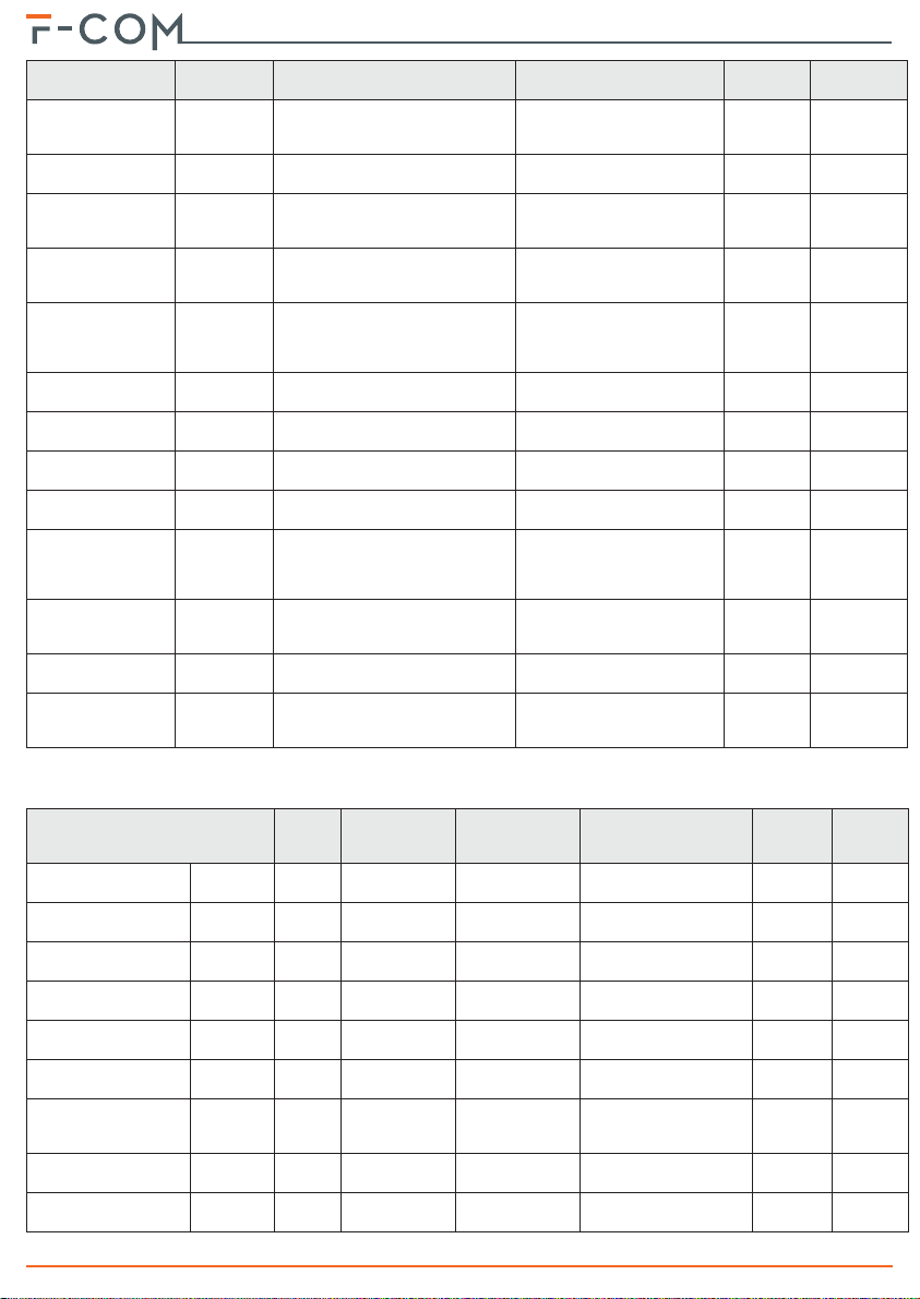
Table 15: Main menu
available for
Item
Faults Yes Yes Yes
Actions Yes Yes Yes
Options No Yes Yes
Phonebook No Yes Yes
Mobile data
network
Date/Time Yes Yes Yes
Language No Yes Yes
Change my
PIN
Events log Yes Yes Yes
Info Yes Yes Yes
Stan-
dard
user
Yes Yes Yes
Advance
d user
No Yes Yes
Installer
description
Section to view the details of ev entual faults.
•Rearm the communicator
• Stop alarm communications
• Stop fault communications
• Stop other types of communications
• Forward remaining credit request
• Force the battery diagnostics update
• Sound on event
•Key press tone
• PSTN channel activation/deactivation
• GSM channel activation/deactivation
• Mobile data network channel activation/deactivation
Section that allows changes the most common programming options
related to telephone contacts: telephone numbers (or IP address/
Section for mobile data network programming: APN, username and
Section for language selection (concerns the user interface and
• Programming version
•Firmware version.
• Communicator serial number
• GSM network diagnostics
• Power supply diagnostics
• Battery diagnostics
Section to perform the following operations:
This last action is available only for the installer
Section to change the following programming options:
port), preferential channel, account code.
password
Section to change the date and time
default voice and SMS messages)
Section to change the PIN of the logged-in user
Section to view the events log
Section to view the following information:
- Registration: home, roaming, none
- Signal strength
- Last credit reading
- Switching power supply voltage
- Output current
- Indication “IN CHARGE” or “IN DISCHARGE”
- Battery voltage
- Current absorbed or supplied by the battery
Note
5-5Main menu
24 Using the communicator

Installation and User manual
Appendix A
EVENTS
The events managed by the communicator are listed in the table below.
The “Events log” column indicates whether the event activation and event
restored data is recorded in the events log.
The “Activate Actions” column indicates whether the communicator can be
programmed to trigger an action when the event occurs.
The “Restores...” column is empty for non-resettable events.
Event Type Activates… Restores... Events log
ALARM CALL Input Alarm
FAULT CALL Input Fault
IO1 Input Generic on activ ation of input IO1 on restore of input IO1 Yes Yes
IO2 Input Generic on activ ation of input IO2 on restore of input IO2 Yes Yes
IO3 Input Generic on activ ation of input IO3 on restore of input IO3 Yes Yes
Output Generic on activation of an output terminal
Interconnection fault Fault
Battery trouble Fault
Missing battery Fault when the battery is disconnected
Power supply trouble Fault
Mains fault Fault when the mains supply fails
Ground fault Fault
Data corruption Fault
System restart Fault
Rearm Generic when the communicator rearms Yes Yes
Factory default Generic
Programming Generic
Changed date/time Generic
PIN entered Generic
Wrong PIN Generic when a wrong PIN is entered Yes Y es
on activation of the ALARM CALL
on activation of the FAULT CALL
when a supervised terminal is
when the battery is inefficient,
discharged or short-ci rcuited
when the power supply is absent,
overloaded or overheated
when leakage to ground is
when the programming data is
when the communicator is
when programming restores to
at the start of a programming
when the communicator date/time
when a user/installer PIN is
input
input
shorted or open
detected
corrupted
restarted
factory default data
session
is refreshed
recognized
on restore of the ALARM
CALL input
on restore of the FAULT CALL
when no terminal is in fault
when the battery has no
when the power supply is
when leakage to ground is no
when the progr amm ing da ta
on exiting a programming
input
on restore of an output
terminal
status
problems
when the battery is
connected
free of problems
when the mains supply
restores
longer detected
is valid
session
Yes Yes
Yes Yes
Yes No
Yes Yes
Yes Yes
Yes Yes
Yes Yes
Yes Yes
Yes Yes
Yes Yes
Yes Yes
Yes No
Yes No
Yes Yes
Yes Yes
Activate
actions
Events 25
Telephone communicator
Event Type Activates… Restores... Events log
T elephone line
trouble
SIM Error Fault
Insufficient SIM
Credit
GSM trouble Fault
Mobile data network
trouble
Communications
cancelled
Communications
enabled/disabled
Communication
started
Communication
confirmed
Failed
communication
Contact supervision
trouble
Code 0 diagnostic
information
Code 1 diagnostic
information
Fault
Fault
Fault
Generic
Generic
Generic at the start of a communication Yes No
Generic
Generic
Fault
Diagnostics
Diagnostics
when the presence of the
telephone line is no longer
detected
when the presence of a GMS SIM
is not detected
when the remaining credit is less
than the programmed threshold
when the communicator fails to
connect to the GSM network or
the signal is weak
when the SIM is not enabled for
data traffic or the communicator
cannot connect to the data
when communications in pr ogress
on confirmation of receipt of a
when a communication is not
confirmed (if the communic ator is
communication is not confirmed
by a supervised telephone contact
when the presence of diagnostic
when the presence of diagnostic
network
are cancelled
when communications are
disabled
communication
programmed to request
confirmation)
when the periodic test
information is detected
information is detected
when the presence of the
telephone line is detected
when the presence of a GM S
SIM is detected
when the remaining credit is
more than the programmed
threshold
when the communicator
connects properly to the GSM
connects to the data network
telephone contacts confi rm
receipt of a communication
network
when the communicator
when communications are
enabled
when all supervised
when the presence of
diagnostic information is
detected
Activate
actions
Yes Yes
Yes Yes
Yes Yes
Yes Yes
Yes Yes
Yes No
Yes No
Yes No
Yes No
Yes No
Yes No
Yes No
Some of the events listed above have actions which are programmed at default.
Event Output Contacts Voice calls SMS text message
ALARM CALL Input activation
FAULT CALL Input activation
Interconnection fault activation
Interconnection fault
Battery fault
No battery
Power supply fault
Mains failure
Ground fault
26 Events
activation/
restore
activation/
restore
activation/
restore
activation/
restore
activation/
restore
activation/
restore
Contacts #1 and
None
None
None
OUT1 None None Empty None None
None
None
None
None
None
#2
Contacts #1 and #2“Fire system
Contacts #1 and #2“Fire system
Contacts #1 and
#2
Contacts #1 and
#2
Contacts #1 and
#2
Contacts #1 and
#2
Contacts #1 and
#2
“Fire alarm” “Fire alarm” 110 FA
trouble”
trouble”
None
None
None
None
None
“Fire system fault” 300 FT
“Interconnection fault” 380 FT
“Battery trouble”/
“Restore battery trouble”
“Missing battery”/
“Restore missing battery”
“Power supply trouble” /
“Restore power supply
trouble”
“Mains fault” / “Restore
mains fault”
“Ground fault” / “Restore
ground fault”
Contact
ID event
SIA-IP/
IP2RX
event
309 YT / YR
311 YM / YR
300 YP / YQ
301 AT / AR
310 UT / UR

Installation and User manual
Event Output Contacts Voice calls SMS text message
Telephone line down
SIM Error
Insufficient SIM Credit
GSM fault
Mobile data network
fault
activation/
restore
activation/
restore
activation/
restore
activation/
restore
activation/
restore
None
None
None
None
None
Contacts #1 and
#2
Contacts #1 and
#2
Contacts #1 and
#2
Contacts #1 and
#2
Contacts #1 and
#2
None
None
None
None
None
“T elephone line trouble” /
“Restore telephone line
trouble”
“SIM error” / “Restore
SIM error”
“SIM credit low” /
“Restore SIM credit low”
“GSM trouble” / “Restore
GSM trouble”
“Mobile data network
trouble” / “Restore
mobile data trouble”
Contact
ID event
SIA-IP/
350 LT / LR
350 YS / YK
350 YS / YK
350 YS / YK
350 YS / YK
IP2RX
event
Events 27

SIMPLIFIED
DECLARATION OF
CONFORMITY
Hereby, INIM ELECTRONICS S.R.L. declares that the radio equipment type F-COM
is in compliance with Directive 2014/53/EU.
The full text of the EU declaration of conformity is available at the following
internet address: www.inim.biz
BG: ǹ ȕȈșȚȖȧȡȖȚȖ INIM ELECTRONICS S.R.L. ȌȍȒȓȈȘȐȘȈ, ȟȍ ȚȖȏȐ ȚȐȗ
ȘȈȌȐȖșȢȖȘȢȎȍȕȐȍ F-COM ȍ Ȋ șȢȖȚȊȍȚșȚȊȐȍ ș ǬȐȘȍȒȚȐȊȈ 2014/53/ǭǹ.
ǾȧȓȖșȚȕȐȧȚ ȚȍȒșȚ ȕȈ ǭǹ ȌȍȒȓȈȘȈȞȐȧȚȈ ȏȈ șȢȖȚȊȍȚșȚȊȐȍ ȔȖȎȍ ȌȈ șȍ ȕȈȔȍȘȐ ȕȈ
șȓȍȌȕȐȧ ȐȕȚȍȘȕȍȚ ȈȌȘȍș: www.inim.biz
CS: Tímto INIM ELECTRONICS S.R.L. prohlašuje, že typ rádiového zaĜízení F-
COM je v souladu se smČrnicí 2014/53/EU.
Úplné znČní EU prohlášení o shodČ je k dispozici na této internetové adrese:
www.inim.biz
DA: Hermed erklærer INIM ELECTRONICS S.R.L., at radioudstyrstypen F-COM er
i overensstemmelse med direktiv 2014/53/EU.
EU-overensstemmelseserklæringens fulde tekst kan findes på følgende
internetadresse: www.inim.biz
DE: Hiermit erklärt INIM ELECTRONICS S.R.L., dass der Funkanlagentyp F-COM
der Richtlinie 2014/53/EU entspricht.
Der vollständige Text der EU-Konformitätserklärung ist unter der folgenden
Internetadresse verfügbar: www.inim.biz
ET: Käesolevaga deklareerib INIM ELECTRONICS S.R.L., et käesolev
raadioseadme tüüp F-COM vastab direktiivi 2014/53/EL nõuetele.
ELi vastavusdeklaratsiooni täielik tekst on kättesaadav järgmisel
internetiaadressil: www.inim.biz
EL: ưİ IJdžnj ȺĮǏǎǘıĮ ǎ/dž INIM ELECTRONICS S.R.L., įdžNJǙnjİLj ǗIJLj ǎ
ǏĮįLjǎİǍǎȺNJLjıNjǗǐ F-COM ȺNJdžǏǎǁ IJdžnj ǎįdžDŽǁĮ 2014/53/ƪƪ.
Ʒǎ ȺNJǀǏİǐ ljİǁNjİnjǎ IJdžǐ įǀNJǔıdžǐ ıǑNjNjǗǏijǔıdžǐ ƪƪ įLjĮIJǁLJİIJĮLj ıIJdžnj ĮljǗNJǎǑLJdž
LjıIJǎıİNJǁįĮ ıIJǎ įLjĮįǁljIJǑǎ: www.inim.biz
ES: Por la presente, INIM ELECTRONICS S.R.L. declara que el tipo de equipo
radioeléctrico F-COM es conforme con la Directiva 2014/53/UE.
El texto completo de la declaración UE de conformidad está disponible en la
dirección Internet siguiente: www.inim.biz
FI: INIM ELECTRONICS S.R.L. vakuuttaa, että radiolaitetyyppi F-COM on
direktiivin 2014/53/EU mukainen.
EU-vaatimustenmukaisuusvakuutuksen täysimittainen teksti on saatavilla
seuraavassa internetosoitteessa: www.inim.biz
FR: Le soussigné, INIM ELECTRONICS S.R.L., déclare que l'équipement
radioélectrique du type F-COM est conforme à la directive 2014/53/UE.
Le texte complet de la déclaration UE de conformité est disponible à l'adresse
internet su ivante: www.inim.b iz
Telephone communicator
Appendix B
28 Simplified declaration of conformity

Installation and User manual
HR: INIM ELECTRONICS S.R.L. ovime izjavljuje da je radijska oprema tipa F-
COM u skladu s Direktivom 2014/53/EU.
Cjeloviti tekst EU izjave o sukladnosti dos tupan je na sljede üoj internetskoj adresi :
www.inim.biz
HU: INIM ELECTRONICS S.R.L. igazolja, hogy a F-COM típusú rádióberendezés
megfelel a 2014/53/EU irányelvnek.
Az EU-megfelelĘségi nyilatkozat teljes szövege elérhetĘ a következĘ internetes
címen: www.inim.biz
LT: Aš, INIM ELECTRONICS S.R.L., patvirtinu, kad radijo šrenginiž tipas F-COM
atitinka Direktyvą 2014/53/ES.
Visas ES atitikties deklaracijos tekstas prieinamas šiuo interneto adresu:
www.inim.biz
LV: Ar šo INIM ELECTRONICS S.R.L. deklarŋ, ka radioiekŅrta F-COM atbilst
Direktŝvai 2014/53/ES.
Pilns ES atbilstŝbas deklarŅcijas teksts ir pieejams šŅdŅ interneta vietnŋ:
www.inim.biz
MT : B'dan, INIM ELECTRONICS S.R.L., niddikjara li dan it-tip ta' tagřmir tar-
radju F-COM huwa konformi mad-Direttiva 2014/53/UE.
It-test kollu tad-dikjarazzjoni ta' konformità tal-UE huwa disponibbli f'dan l-
indirizz tal-Internet li œej: www.inim.biz
NL: Hierbij verklaar ik, INIM ELECTRONICS S.R.L., dat het type radioapparatuur
F-COM conform is met Richtlijn 2014/53/EU.
De volledige tekst van de EU-conformiteitsverklaring kan worden geraadpleegd op
het volgende internetadres: www.inim.biz
PL: INIM ELECTRONICS S.R.L. niniejszym oĞwiadcza, Īe typ urządzenia
radiowego F-COM jest zgodny z dyrektywą 2014/53/UE.
Peány tekst deklaracji zgodnoĞci UE jest dostĊpny pod nastĊpującym adresem
internetowy m: www.inim.biz
PT: O(a) abaixo assinado(a) INIM ELECTRONICS S.R.L. declara que o presente
tipo de equipamento de rádio F-COM está em conformidade com a Diretiva 2014/
53/UE.
O texto integral da declaração de conformidade está disponível no seguinte
endereço de Internet: www.inim.biz
RO: Prin prezenta, INIM ELECTRONICS S.R.L. declară că tipul de echipamente
radio F-COM este în conformitate cu Directiva 2014/53/UE.
Textul integral al declaraΌiei UE de conformitate este disponibil la următoarea
adresă internet: www.inim.biz
SK: INIM ELECTRONICS S.R.L. týmto vyhlasuje, že rádiové zariadenie typu F-
COM je v súlade so smernicou 2014/53/EÚ.
Úplné EÚ vyhlásenie o zhode je k dispozícii na tejto internetovej adrese:
www.inim.biz
SL: INIM ELECTRONICS S.R.L. potrjuje, da je tip radijske opreme F-COM skladen
z Direktivo 2014/53/EU.
Celotno besedilo izjave EU o skladnosti je na voljo na naslednjem spletnem
naslovu: www.inim.biz
SV: Härmed försäkrar INIM ELECTRONICS S.R.L. att denna typ av
radioutrustning F-COM överensstämmer med direktiv 2014/53/EU. Den
fullständiga texten till EU-försäkran om överensstämmelse finns på följande
webbadress: www.inim.biz
Simplified declaration of conformity 29

Telephone communicator
30 Simplified declaration of conformity

Installation and User manual
Information on electrical and electronic device disposal
The barred bin symbol found on the equipment or its box indicates that the
product must be discarded separate from other waste at the end of its working
life.
Therefore, the user must take the decommissioned equipment to suitable
electrical and electronic waste disposal centers.
In alternative to independent management, the equipment to be discarded can be
taken to the dealer upon purchase of a similar new device.
Electronic devices sized under 25 cm can be taken to electronic product dealers
with at least 400 m2 store surface free of charge without any purchase obligation.
Suitable collection for subsequent recycling, processing and compatible
environmental disposal contributes in avoiding potential negative effects on the
environment and health and promotes the reuse and/or recycling of equipment
materials.
(applicable in countries with recycling systems)
WEEE
31

Telephone communicator
Via dei Lavoratori 10, Loc. Centobuchi
63076 Monteprandone (AP) ITALIA
Tel. +39 0735 705007 _ Fax +39 0735 704912
info@inim.biz _ www.inim.biz
32
ISO 9001 Quality Management
certified by BSI with certificate number FM530352
 Loading...