

INID XS series, SmartReader XS PIN, MultiSmart XS PIN, SmartReader XS, MultiSmart XS Installation Manual
...
INID XS readers Installation Manual
Models
number name interfaces
article
number
5040C INID SmartReader XS PIN WG/C&D/TTL + RS485 500-5040C
5000C INID SmartReader XS WG/C&D/TTL + RS485 500-5000C
5045C INID MultiSmart XS PIN WG/C&D/TTL + RS485 500-5045C
5005C INID MultiSmart XS WG/C&D/TTL + RS485 500-5005C
5240C INID SmartProx XS PIN WG/C&D/TTL + RS485 500-5240C
5200C INID SmartProx XS WG/C&D/TTL + RS485 500-5200C
Classifications
UL 294: destructive attack level IV, line security level I,
endurance level IV, standby power level I
ULC S319: class III
Specifications
Dimensions
143 x 50 x 25 mm / 5⅝ x 2 x 1 inch
Operating temperature
-25° to 65° C / -15° to 150° F
Protection class
IP54 Complete protection against contact, protection
against dust deposit.
Protection from splashed water.
Power Supply
All models 7.0 - 24 Volt DC
models
Watts
mA
at V
min
at 12 VDCat V
max
avg peak avg peak avg peak avg peak
5000C INID SmartReader XS 1,50 2,35 215 340 125 200 65 100
5040C INID SmartReader XS PIN 1,50 2,55 215 365 125 215 65 110
5005C INID MultiSmart XS 1,50 2,35 215 340 125 200 65 100
5045C INID MultiSmart XS PIN 1,50 2,55 215 365 125 215 65 110
5200C INID SmartProx XS 0,85 2,00 125 290 75 170 40 85
5240C INID SmartProx XS PIN 0,85 2,00 125 290 75 170 40 85
Note: Ohms’ Law may be used to estimate current at other voltages.
Parts included (1 each)
Reader front
Mounting backplate
Enclosure screw (Torx #8)
Installation manual
Certifications
CE, FCC, IC, UL, ULC
FCC ID: YAB-MSX SRDR (MultiSmart XS readers)
YAB-SPX SR DR (SmartProx XS readers)
YAB-SRXSR DR (SmartReader XS readers)
IC: 8908A -MSXSRD R (MultiSmart XS readers)
8908A- SP XSRD R (SmartProx XS readers)
8908A- SRXSRDR (SmartReader XS readers)
Consult your National Authority if any authorization is needed for
these products.
Warning (part 15.21)
Changes or modifications not expressly approved by the party
responsible for compliance could void the user’s authority to operate
the equipment.
Compliance statement
This device complies with part 15 of the FCC Rules and with the
Industry Canada license-exempt RSS standard(s).
Operation is subject to the following two conditions:
(1) this device may not cause harmful interference, and
(2) this device must accept any interference received, including
interference that may cause undesired operation.
Le présent appareil est conforme aux CNR d’Industrie Canada
applicables aux appareils radio exempts de licence. L’exploitation est
autorisée aux deux conditions suivantes :
(1) l’appareil ne doit pas produire de brouillage, et
(2) l’utilisateur de l’appareil doit accepter tout brouillage
radioélectrique subi, même si le brouillage est susceptible d’en
compromettre le fonctionnement.
Information to the User (Part 15.105 (b))
Note: This equipment has been tested and found to comply with the
limits for a Class B digital device, pursuant to part 15 of the FCC Rules.
These limits are designed to provide reasonable protection against
harmful interference in a residential installation. This equipment
generates, uses and can radiate radio frequency energy and, if not
installed and used in accordance with the instructions, may cause
harmful interference to radio communications. However, there is no
guarantee that interference will not occur in a particular installation. If
this equipment does cause harmful interference to radio or television
reception, which can be determined by turning the equipment off and
on, the user is encouraged to try to correct the interference by one or
more of the following measures:
— Reorient or relocate the receiving antenna.
— Increase the separation between the equipment and receiver.
— Connect the equipment into an outlet on a circuit different from that
to which the receiver is connected.
— Consult the dealer or an experienced radio/TV technician for help.
Complies with: CAN ICES-3 (B)/NMB-3(B)
Operation
When a credential is read successfully, the LED bar lights briefly, the
sounder sounds a short tone and the credential associated code is sent
to the Host system.
The LED bar and sounder are also controllable by the Host system.
When a PIN is entered the data is sent to the Host system; at each key
press a click sound is produced and the LED bar lights briefly. The
backlight of the PIN code lights up after a successful credential read, or
at the first key press.
Reader output formats are determined by the personalization of the
credential and/or configuration of the reader; on SmartReader and
MultiSmart readers the behaviour of the LED bar and sounder can be
modified through configuration.
When the reader detects a tamper status, the LED bar flashes red and
the tamper output is activated; on SmartReader and MultiSmart
readers this behaviour can be modified through configuration.
Document 100.14.IS.01 v1.30, effe ctive from SN1632-0001 page 1 of 2 printed on Aug 8, 2016
INID BV
Overweg 5
1713 HX Obdam
The Netherlands
Phone: +31 (0)226 450 009
Web: www.inid-readers.com
INID XS readers Installation Manual
Cable specifications
Shi elded ca ble is requ ired for ULC S3 19 compl iance.
The use of stranded conductors cable is highly recommended.
Restrict oversizing the cable to a maximum of two sizes.
interface
max. cable length min. conductor size
1)
meters feet mm
2
AWG
Wiegand
61 200
0.25 24
91 300
152 500 0.34 22
Clock / Data 25 80
0.25 24
TTL serial 1.5 5
RS485 (cable power)
61 200 0.25 24
152 500 0.34 22
RS485 (local power) 1220 4000 0,16 25
1)
With a 12 V supp ly. With a 24 V supply, minimum conductor size is AWG 24 (0.25mm2) for
all interfaces and len gths.
For locally powered readers the minimum conductor size is AWG 25 (0.16mm2) for all
interfaces and lengths.
Connector Assignments
interface
connector position
1 2 3 4 5 6 7 8
Wiegand LED1-green LED2-red D1 D0 BUZZER TAMPER GND POWER
Clock/Data LED1-green LED2-red DATA CLOCK BUZZER TAMPER GND POWER
TTL serial LED1-green LED2-red TXD TXE RXD TAMPER GND POWER
RS485
standard LED1-green LED2-red
TRX+ TRX-
N.C.
TAMPER GND POWER
OSDP INPUT 1 INPUT 2 INPUT 3
Caution
Floating communication lines may cause spurious emissions, invalidating certification.
Ensure all communication lines are properly biased and terminated.
SmartProx XS DIP switch settings
1 2 3 4 5 6 7
factory default:
all switches off.
card
type
output
format
PIN
format
1)
off off H-PX & A-PX
off on EM4102
on off PX light
on on QKEY
off off off AUTO (H-PX & A-PX only)
off off on WG 26
off on off WG 32
off on on WG 34
on off off WG 37
on off on WG 40
on on off WG 42
on on on ABA 10
off off WG 4
off on WG 8
on off WG 4+4
on on CLK/DTA trk2 ABA
Note
Selecting AUTO format for cards EM4102, PX light or QKEY will cause
unpredictable behaviour.
1)
Not functional in readers without PIN pad.
Installation instructions
All wiring shall be in accordance with appliccable
codes and regulations
(USA: ANSI/NFPA70; Canada: CSA C22.1)
1. Determine an appropriate position for the reader; a height of
140 cm (55 inches) above floor level on the doorjamb at the lock
side of the door is recommended.
Observe applicable building codes and safety regulations in
determining the reader position.
Notes:
╺ Mounting readers in close proximity of each other wil reduce
performance. The minimum recommended mounting distance
side-by-side or back-to-back is 125mm (5”). Closer mounting will
reduce performance, or cause unintentional reads on the other
reader; magnetic shielding may be necessary in that case.
╺ Mounting the reader on a metal surface will reduce performance,
a plastic separator of at least 6mm (¼”) is recommened.
╺ See Application Note AN100.14001 on the INID website for more
details.
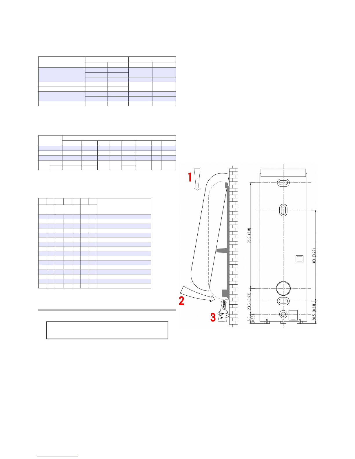
2. Drill two pilot holes for mounting the backplate and one hole for the
cable, see drawing for measurements.
3. Pull the cable trough the hole in the backplate; protect the cable
against sharp edges and any damage from chafing.
4. Mount the backplate using flat head screws with a shank size of
4mm (5/32”, #7) or smaller; other screw types or sizes may cause
irrepairable damage to the reader.
5. Prepare the end of the cable and wires, eliminating any loose or
frayed strands; for stranded conductors, the use of ferrules is highly
recommended.
Keep the wire ends as short as practical.
6. Connect the wires to the connector according to the interface type.
Wire ends, termination resistor leads and optional permanent links
shall be kept as short as possible.
Use an appropriate sized screwdriver and do not over-tighten the
connector screws.
7. Place the reader front section over the hinge of the backplate (see
drawing) and close the reader, keeping the wiring in the lower part
of the reader housing. DO NOT use excessive force, retract the
cable if necessary.
8. Test the reader: apply power and present a valid credential. The
LED bar should flash and the sounder should produce a short tone
indicating a successful read. If the Host system is connected to the
LED bar and sounder inputs these should follow the functionality of
the Host system.
Note:
The reader must be fully closed or the tamper circuit will
activate, indicated by a flashing LED bar.
9. The reader front can now be secured to the backplate using the
supplied enclosure screw.
use ON LY flat head screws, maximum shank size 4mm (5/32”, #7)
Document 100.14.IS.01 v1.30, effe ctive from SN1632-0001 page 2 of 2 printed on Aug 8, 2016
 Loading...