

Page 1
NGRP-AOLF Installation manual
DISCLAIMER:
This procedure is only to be carried out by
personnel trained and authorized by INID.
Scope
This document is valid for NGRP-AOLF modules model 4000 and 4000A; since the modules only differ in
antenna appearance and not in installation details only model 4000 is shown in the photos.
Prerequisites
‣ Always disconnect the power supply of the unit.
‣ Perform these actions on an ESD-safe workbench in a suitable location.
‣ Take appropriate measures against ESD damages of the equipment.
Required equipment:
‣ Torx® #6 screwdriver, manual type recommended
‣ Soldering iron (40-60 Watts pencil-type recommended) with lead-free compatible tip (1.5mm chisel-
type recommended)
‣ Lead-free solder wire, 0.7mm rosin-core recommended
Recommended equipment:
‣ Torx® #8 screwdriver, manual type recommended (required for removing reader from wall)
‣ De-soldering wick, 1 à 2mm width recommended
‣ Needle-nosed pliers or fine-pointed tweezers
Step by step instructions
A. DISASSEMBLY
1. Unpackage the reader and remove the
backplate and connector, or, remove the
reader from the wall and disconnect it.
2. Protect the reader housing from scratches
or other damage.
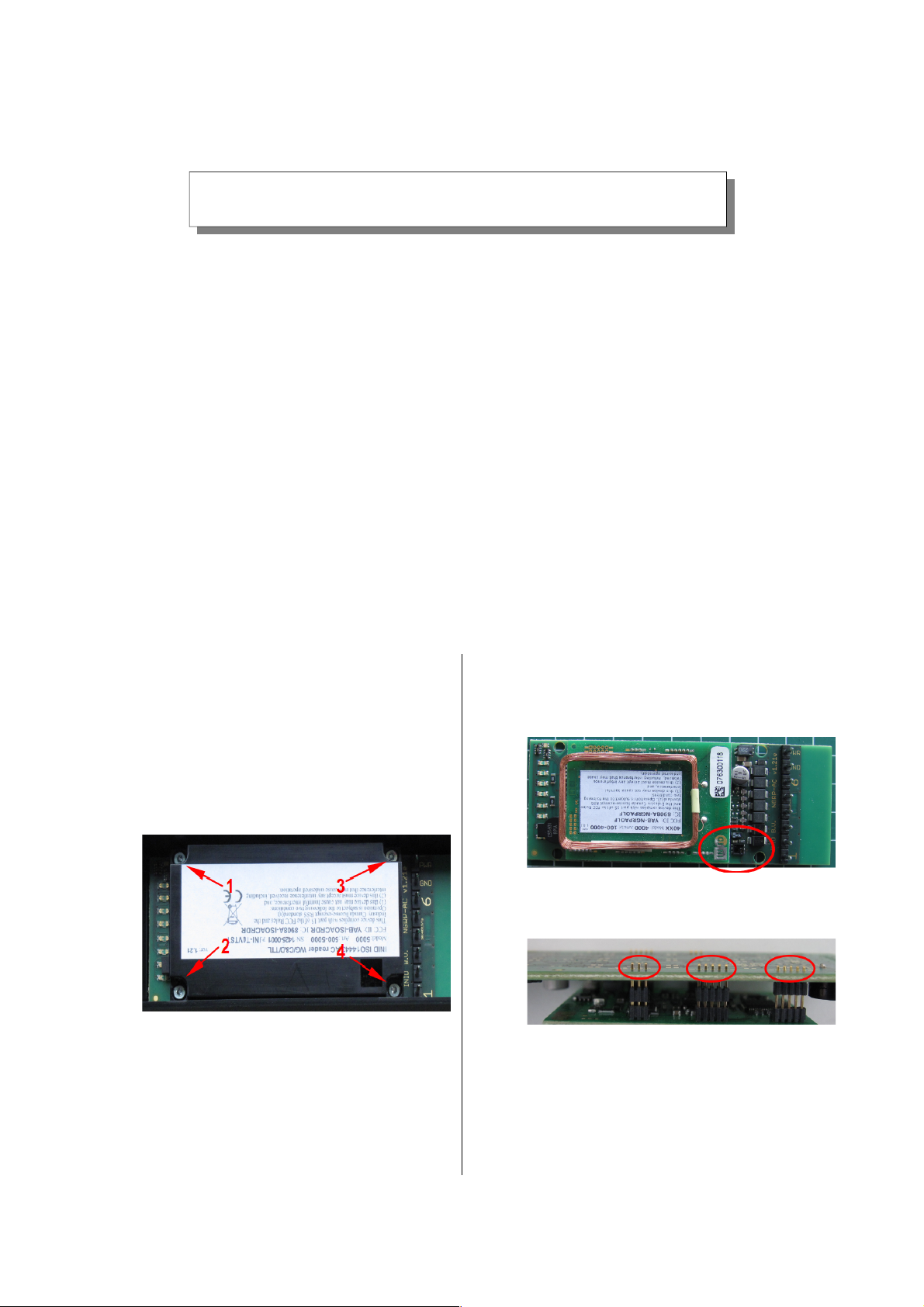
3. Remove the four screws that keep the
electronics cover onto the reader in the
order specified:
4. Remove the electronics cover.
5. Remove the printed circuit board from the
reader.
B. MOUNTING & CHECK
1. Fit the NGRP-AOLF module onto the reader
printed circuit board. Pay attention to the
correct orientation :
2. Make sure that all pins are properly lined
up and inserted to the correct depth; the
pins should not protrude more than 1mm:
3. Solder all the pins to the main board using
lead-free solder.
4. Connect power to the reader PCB, the
reader should start op normally.
If not, check for shorts or cold joints on
soldering and correct where necessary.
v2.03a, May 29, 2015 1/2 (c) INID BV All rights reserved
Page 2

NGRP-AOLF Installation manual
C. RE-ASSEMBLY
1. Place the reader printed circuit board with
the NGRP-AOLF module back in the reader
enclosure.
2. Replace the product label, or, alternatively,
add the correct additional product label
(shown is the additional label for model
4000):
3. Reposition the electronics cover over the
four screw posts, observe correct
orientation.
4. Replace the four electronics cover screws in
the reverse order listed in step A4.
Attempt to engage the old thread and
avoid excessive force to prevent damage to
the housing and screw posts.
D. PROGRAMMING & VERIFICATION
1. Connect power to the reader and load the
parameters for the low frequency module
2. Perform a functionality test with the
appropriate ISO14443 and low frequency
proximity cards.
E. FINISHING
1. Repackage the reader with the appropriate
manual(s) and affix the correct label to the
box, or, remount the reader to the wall.
Warning (part 15.21)
Changes or modifications not expressly approved
by the party responsible for compliance could void
the user’s authority to operate the equipment.
Compliance statement
This device complies with part 15 of the FCC Rules
and with the Industry Canada license-exempt RSS
standard(s).
Operation is subject to the following two conditions:
1) this device may not cause harmful interference,
and
2) this device must accept any interference
received, including interference that may cause
undesired operation.
Le présent appareil est conforme aux CNR
d’Industrie Canada applicables aux appareils radio
exempts de licence. L’exploitation est autorisée aux
deux conditions suivantes :
l’appareil ne doit pas produire de brouillage, et
l’utilisateur de l’appareil doit accepter tout
brouillage radioélectrique subi, même si le
brouillage est susceptible d’en compromettre le
fonctionnement.
v2.03a, May 29, 2015 2/2 (c) INID BV All rights reserved
INID BV
Overweg 5
1713 HX Obdam
The Netherlands
T: +31 (0)226 450 009
W: www.inid-readers.com
 Loading...