

Page 1
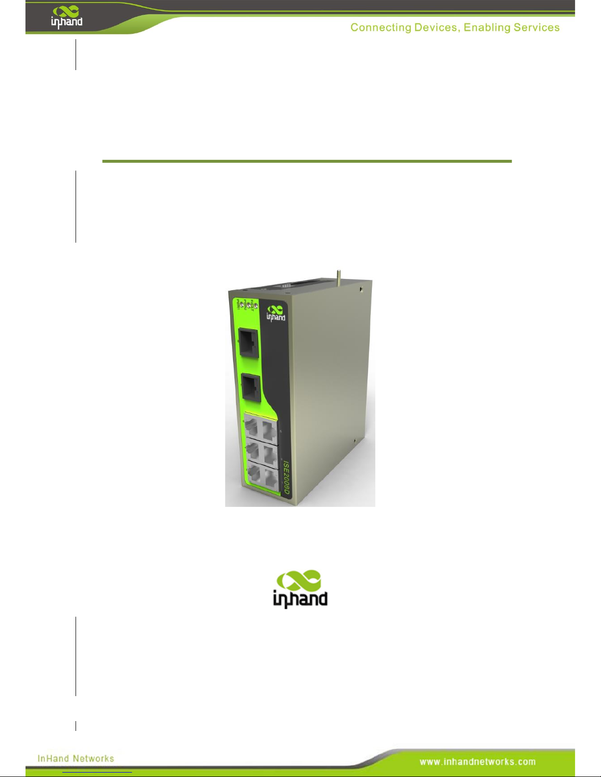
InSwitch Industrial Ethernet Switch
ISE Series User Manual
Version 3.5
InHand Networks
Page 2
User’s Manual for InSwitch ISE Series Products
Copyright Statement
copyright © 2016 InHand Networks. All right reserved and no reproduction
allowed without permission. Subjet to change without warning.
Trademark
InHand and InHand Networks are registered trademarks InHand Networks and all
other trademarks or registered trademarks in the manual belong to corresponding
manufacturers.
Disclaimer
InHand shall not be taken responsible for any modification of contents of the manual
made without permission.
This manual may contain some technical or printing errors due to human error. These
errors will be corrected periodically and will be avoided in reprint.
InHand reserves hereby the right to amend this manual without further notice to users.
Please log in our website or contact our business agent directly for revision status of
the manual.
Contact Information for Technical Support
3900 Jermantown Rd., Suite 150
Fairfax, VA 22030
USA
T: +1-703-348-2988
F:+1-703-348-2988
Page 3
Safety Instructions
The product has excellent and reliable performance within its designed use, however
damage to the ISE switch should be avoided.
Please read the manual carefully and keep it for later reference.
Please pay attention to the follows when using the equipment:
Do not place the equipment close to water or wet places.
Do not place anything on power cable, which shall be kept out of reach.
Do not cover, tie or wrap-up the power cable in order to prevent fire.
Inspect the power cable and other connections regularly to ensure they are
not damaged and well connected.
Please keep the socket and plug of the optical fiber clean ,and do not looking
directly the into cross section of optical fiber during operation of the equipment.
Keep the equipment clean and wipe with soft cotton cloth when necessary.
Unless other wise instructed in the manual, please do not try to repair the
equipment by yourself.
Please disconnect power source immediately under the following circumstances and
then contact InHand Networks.
Entering of water into the equipment.
Physical damage to the equipment or cracking of the casing.
Abnormal equipment behavior or a complete change in performance.
Gas, smoke or noise generated by the equipment.
Page 4
Brief Introduction to the ISE Manual
The manual is applicable for ISE2005D, ISE2008D,ISE2016D,ISE3005D,
ISE3008D,ISE3009D,ISE3010D,ISE3018D of ISE series products.
The manual contains the following chapters:
Package contents . List of goods that should be contained in packing box of
the equipment.
Product introduction. Brief introduction of the product and outstanding
features thereof.
Front panel and dimension. Front panel diagram and dimension of each and
every product of ISF series are provided.
Installation. Installation method is given in details to guide users to install the
equipment correctly.
Cable connection. Description of correct methods for connecting power
cables and communication cables.
Introduction of functions. Detailed description of features and uses.
Specifications and parameters. Description of codes and standards observed
by the product, and product specifications and parameters.
Networking models. Briefly explain the common networking models for the
ISE series switch.
Readers are instructed to read the contents carefully when the following icons are
present in the manual. Example of the icons are listed in the following table.
Note: Supplementary to main text.
Warning: Function may not be available or damage of equipment may
occur if operational instructions are not followed.
Danger: Bodily injury may occur if operation instruction is not
followed.
Page 5
Contents
ISE Series User Manual .................................................................................................................. 1
Safety Instructions ............................................................................................................................ 3
Brief Introduction to the ISE Manual ................................................................................................ 4
II. Product Introduction ..................................................................................................................... 8
2.1 General ................................................................................................................................ 8
2.2 Outstanding Product Features ............................................................................................. 8
III. Front Panel and Dimension ......................................................................................................... 9
3.1 ISE2005D ............................................................................................................................ 9
3.2 ISE2008D .......................................................................................................................... 12
3.3 ISE2016D .......................................................................................................................... 14
3.4 ISE3008D .......................................................................................................................... 16
3.5 ISE3009D .......................................................................................................................... 18
3.6 ISE3010D .......................................................................................................................... 20
3.7 ISE3018D .......................................................................................................................... 22
IV. Installation ................................................................................................................................. 25
4.1 Instruction for DIN-Rail Installation ................................................................................. 25
4.1.1 DIN-Rail Mounting ................................................................................................ 25
4.1.2 DIN-Rail Removal ................................................................................................. 25
4.2 Instruction for Wall mounting ........................................................................................ 26
4.2.1 Wall mount ............................................................................................................. 26
4.2.2 DIN-Rail Dismount ................................................................................................ 27
V. Ethernet Cables and Wiring ........................................................................................................ 28
5.1 10/100Base-T(X) port ....................................................................................................... 28
5.2 100Base-FX port ............................................................................................................. 30
5.3 1000Base-X, 1000Base-T(X) SFP Port ........................................................................... 30
5.4 Power Source .................................................................................................................... 32
5.5 Grounding Protection ........................................................................................................ 34
5.6. Alarm ................................................................................................................................ 35
VI. Functions and Features ............................................................................................................. 36
6.1 LED Indicator Codes ........................................................................................................ 36
6.2. Dip Switches .................................................................................................................... 37
6.3 Introduction to Alarms ...................................................................................................... 38
VII. Specifications .......................................................................................................................... 39
VIII. Networking Mode .................................................................................................................. 40
8.1 Networking of Single Set of Equipment ........................................................................... 40
8.2 Networking of Multiple Sets of Equipment ...................................................................... 41
Appendix 2 Glossary of Terms........................................................................................................ 42
Appendix 3 FCC STATEMENT ....................................................................... 错误!未定义书签。
Appendix 4 Important Safety Information ...................................................................................... 44
Page 6
Page 7
I. Package Contents
Common accessories are provided for each set of ISE series products (as shown in list
of standard accessories). Please check our package carefully after taking delivery and
contact InHand sales personnel in a timely manner if any piece is missing or
damaged.
In addition, InHand can also provide users with optional accessories as per different
field conditions and customer requirements. Please refer to list of optional accessories
for details.
Standard Accessories
Accessory
Qty.
Description
Industrial Ethernet
switch
1 Device
InSwitch ISE series switch
Product documents
1 Package
Optical disk
DIN-rail
1 Piece
Fixed type switch
Product warranty
statement
1 Sheet
Warranty period is 5 years.
Optional accessories
Accessory
Qty.
Description
220VAC-24VDC
adapter
1 Set
InSwitch ISF series switch
1m optical
jumper wire
1 Piece
For user testing
Installation
accessorions
1 Set
1 piece wall-mounting accessory and 4
screws
Page 8
II. Product Introduction
2.1 General
The ISE1005D series switches are designed for applications in electric power,
transportation, industrial control and other severe industrial environments. They
integrates a wide temperature range, high voltage tolerance, enterprise-class
forwarding performance, high-bandwidth, strong cabinet, protected industrial circuits
and other industrial features. They are capable of plug and play, and can satisfy
reliability requirements in the harsh industrial environment.
2.2 Outstanding Product Features
High-performance Ethernet switch technology:
IEEE802.3/802.3u/802.3x
Flow control (full duplex and half duplex flow control)
Automated speed and duplex negotiation
Broadcast storm protection
Store-and-forward switching mode
10/100M full duplex/half duplex MDI/MDI-X self adaptive
Reliable and steady operation in severe electrical environments:
Passed high-standard electromagnetic compatibility tests
Zero packet loss under intensive electromagnetic interference
Suitable for application under various severe conditions and environment:
Working temperature: -40~85 ℃
Relative humidity: 5%~95% (free of condensation)
IP40 protection class, fully enclosed and seamless type metal cabinet, and
fanless cooling
Pollution degree 2
Satisfying industrial installation requirement:
Standard industrial DIN rail or wall-mount type installation
Industrial power source terminal or I/O terminal
PCB protection coating available
Network reliability enhanced with redundancy and alarms:
Page 9
Dual power-supply redundant inputs
A warning can be produced via relay after power supply failure and
interruption of port connections
III. Front Panel Layout and Dimensions
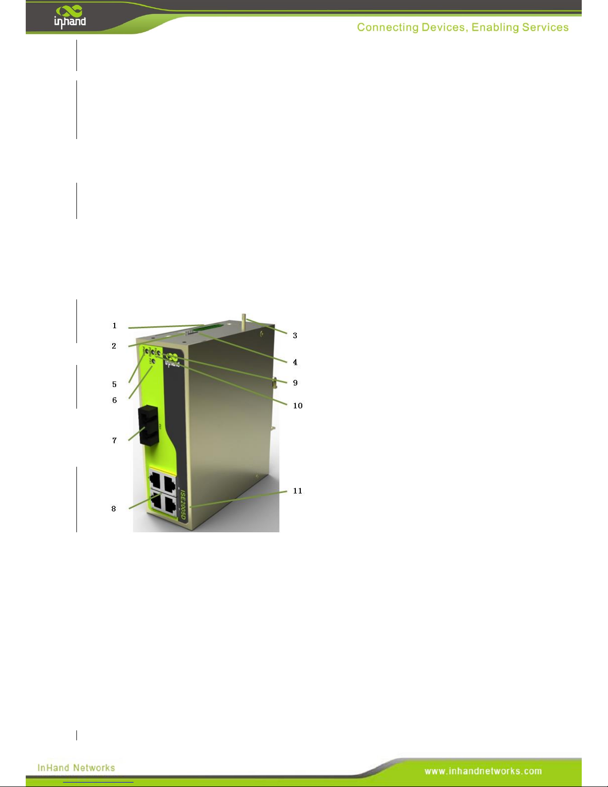
3.1 ISE2005D
Front Panel Layout
1. Power source connection and alarm
connection terminal
2. DIP switch
3. Grounding screw
4. Cover plate
5. Power source one indicator lamp
6. FX2 LINK/ACT indicator lamp
7.100Base-FX single mode/multimode
FC/SC/ST interface FX1
8. 10/100Base-T(X) RJ45 interface
9. Alarm indicator lamp
10. Power source two indicator lamp
11. InSwitch model number
Page 10
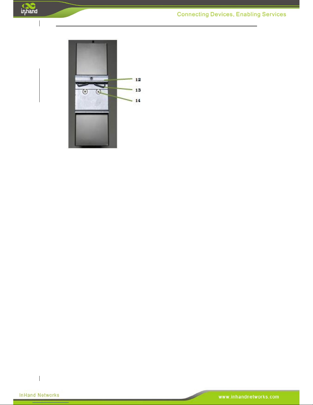
12. DIN-rail bracket upper lip
13. Clamping spring
14. DIN-rail bracket attachment screw
Page 11
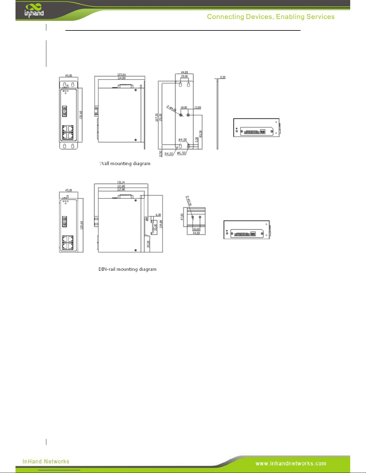
Structural Dimensions
(Units: mm)
Page 12
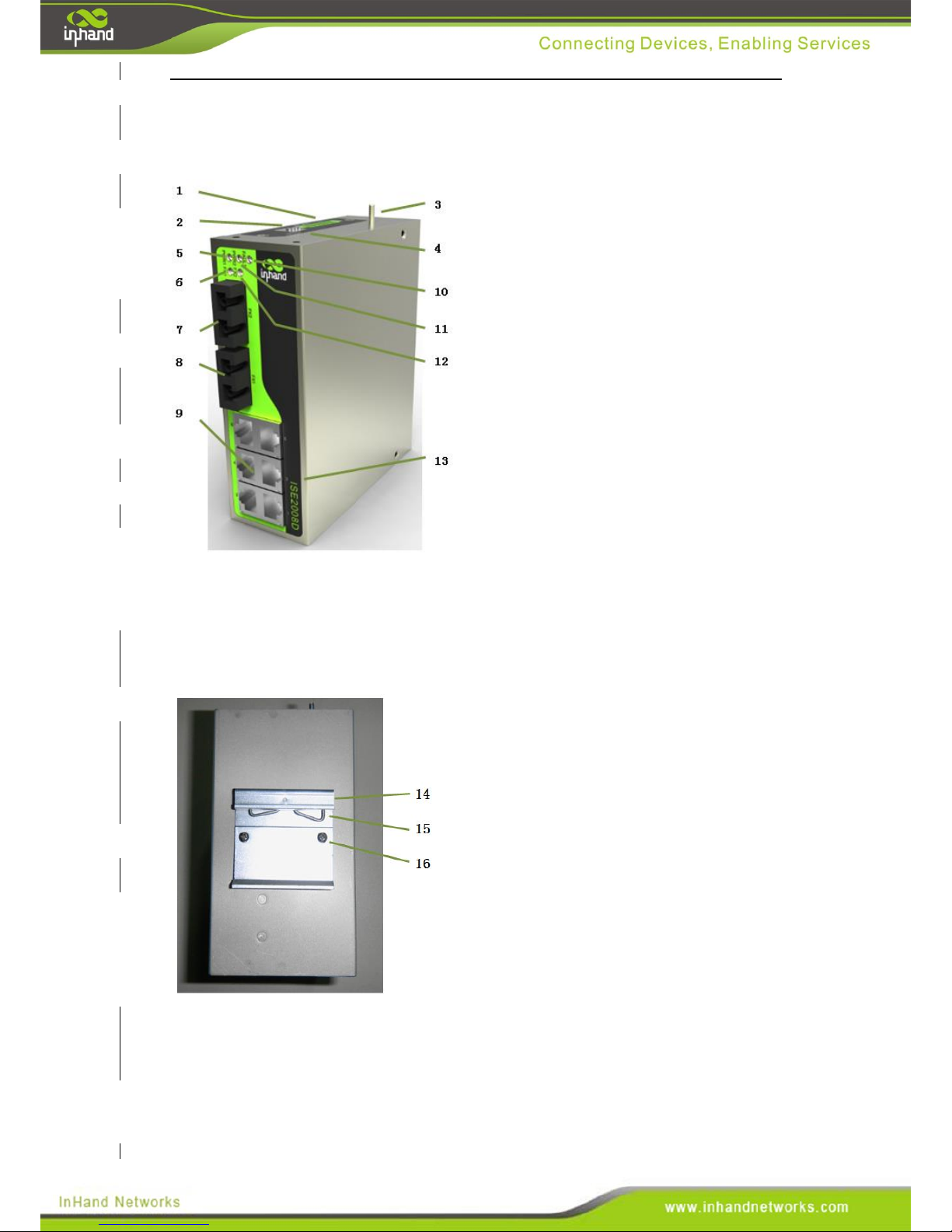
3.2 ISE2008D
Front Panel Layout
1. Power source connection and alarm
connection terminal
2. Dip switch
3. Protective grounding screw
4. Cover plate
5. Power source one indication lamp
6. Optical port FX1 LINK/ACT
indication lamp
7. 100Base-FX single mode/multimode
FC/SC/ST interface FX1
8. 100Base-FX single mode/multimode
FC/SC/ST interface FX2
9. 10/100Base-T(X) RJ45
10. Alarm indication lamp
11. Power source two indication lamp
12. Optical port FX2 LINK/ACT
indication lamp
13. InSwitch model number
14. DIN-rail bracket upper lip
15. Clamp spring
16. DIN-rail bracket attachment screw
Page 13
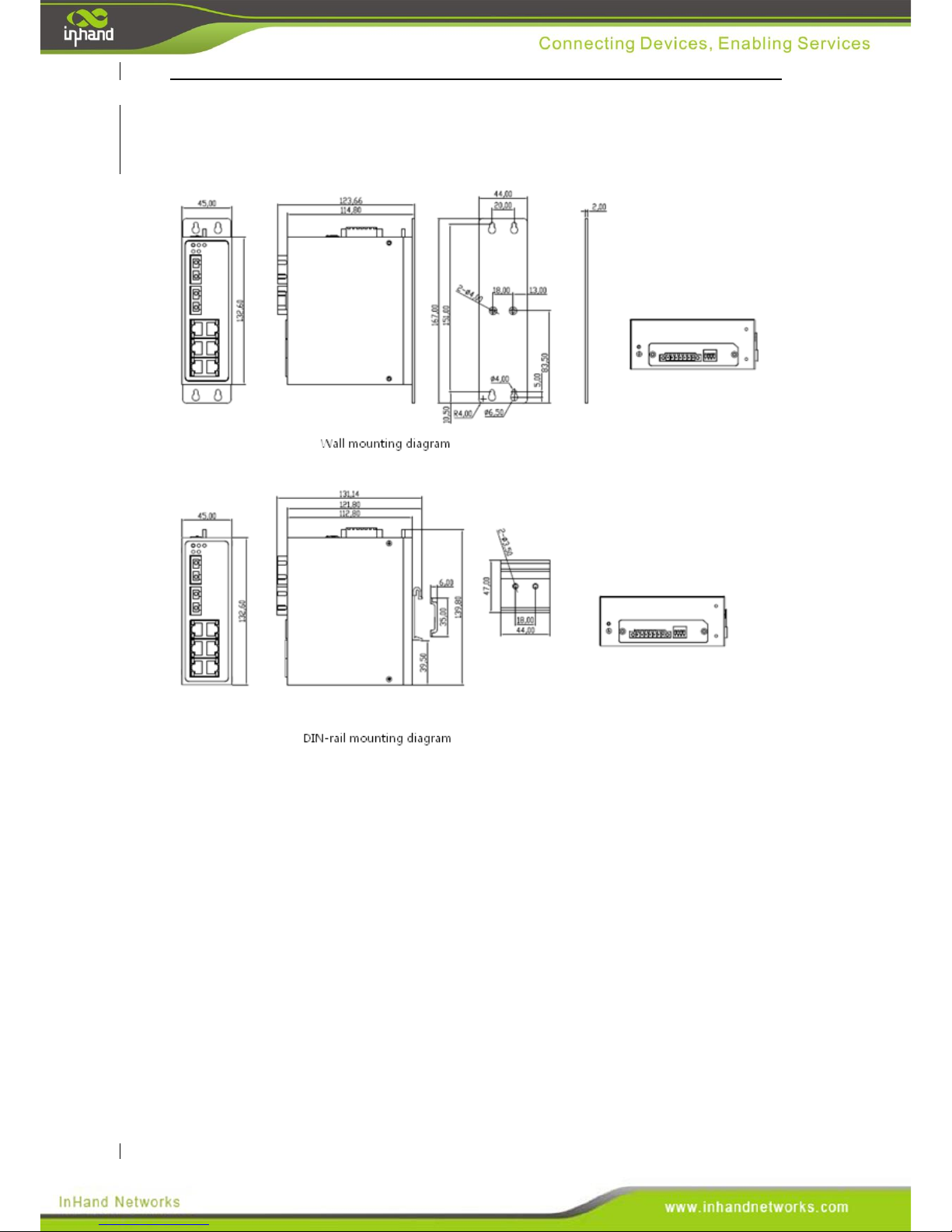
Structural Dimensions
(Units: mm)
Page 14
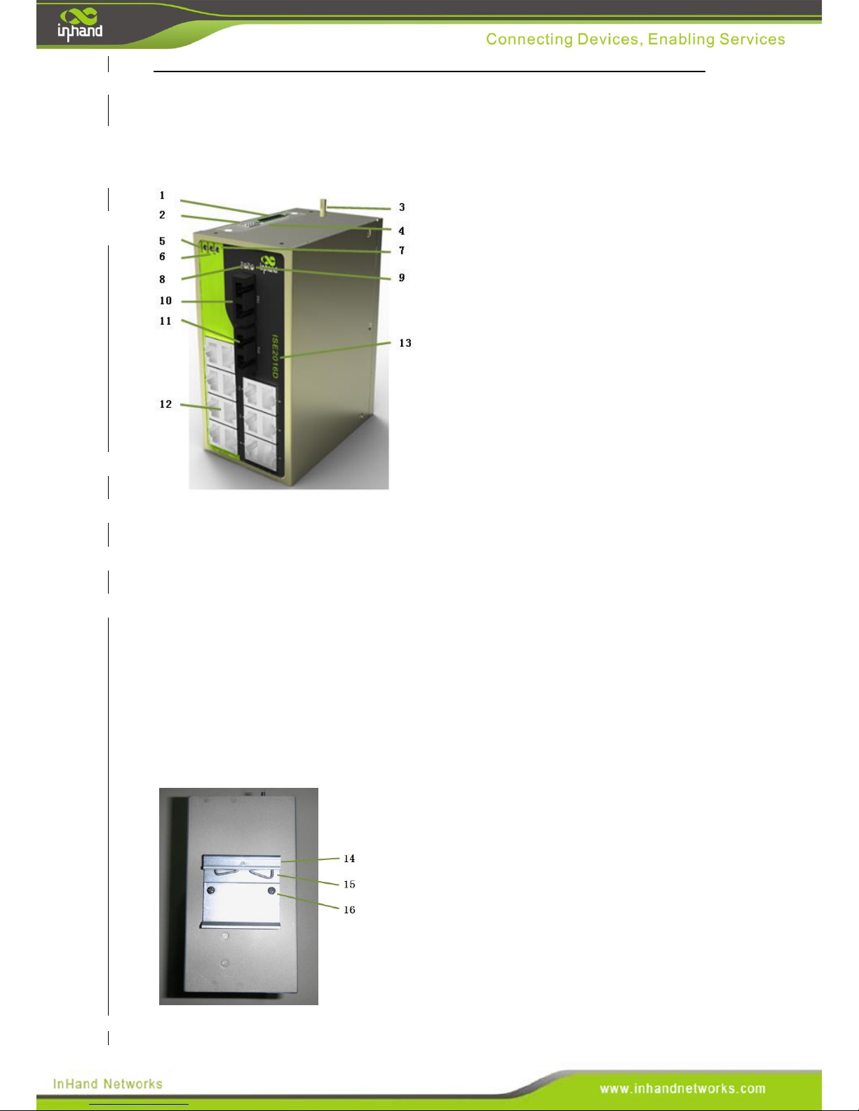
3.3 ISE2016D
Front Panel Layout
1. Power source connection and alarm
connection terminal
2. Dip switch
3. Grounding screw
4. Cover plate
5. Power source one indication lamp
6. Power source two indication lamp
7. Alarm indication lamp
8. Optical port FX1 LINK/ACT
indication lamp
9. Optical port FX2 LINK/ACT
indication lamp
10. 100Base-FX single mode/multimode
FC/SC/ST interface FX1
11. 100Base-FX single mode/multimode
FC/SC/ST interface FX2
12.10/100Base-T(X) RJ45 port
13. InSwitch model number
14. DIN-rail bracket upper lip
15. Clamp spring
16. DIN-rail bracket attachment screw
Page 15
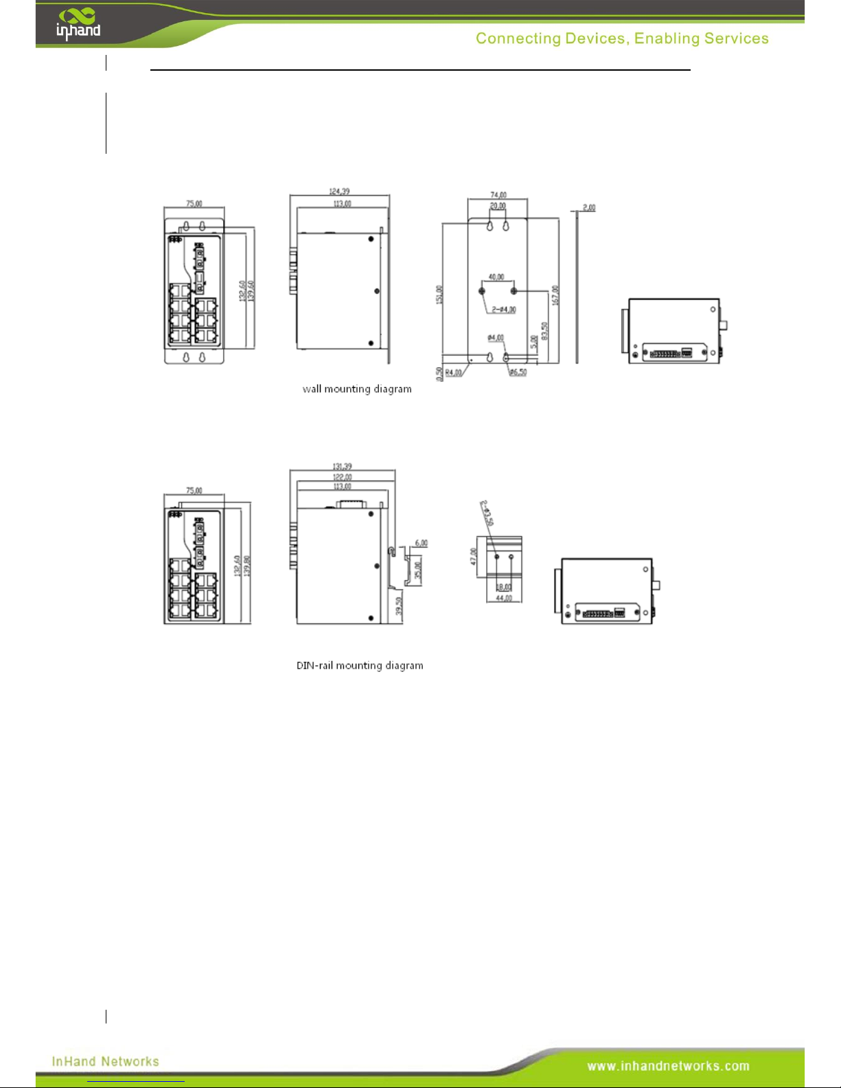
Structural Dimensions
(Units: mm)
Page 16
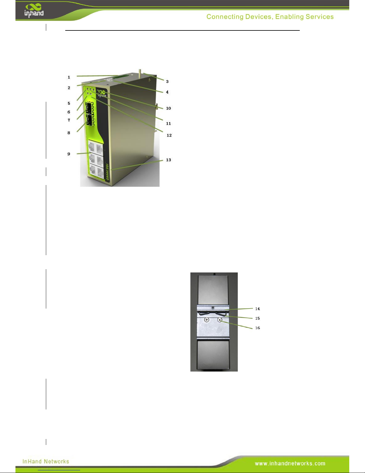
3.4 ISE3008D
Front Panel Layout
1. Power source connection and alarm
connection terminal
2. Dip switch
3. Grounding Screw
4. Cover plate
5. Power source one indication lamp
6. GX1 LINK/ACT indication lamp
7. 1000Base-X, 1000Base-T(X) SFP
port GX1
8. 1000Base-X, 1000Base-T(X) SFP
port GX2
9. 10/100Base-T(X) RJ45 port
10. Alarm indication lamp
11. Power source two indication lamp
12. GX2 LINK/ACT indication lamp
13. InSwitch model number
14. DIN-rail bracket upper lip
15. Clamp spring
16. DIN-rail bracket attachment screw
Page 17
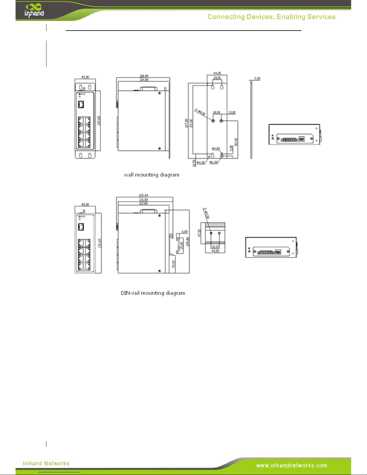
Structural Dimensions
(Units: mm)
Page 18
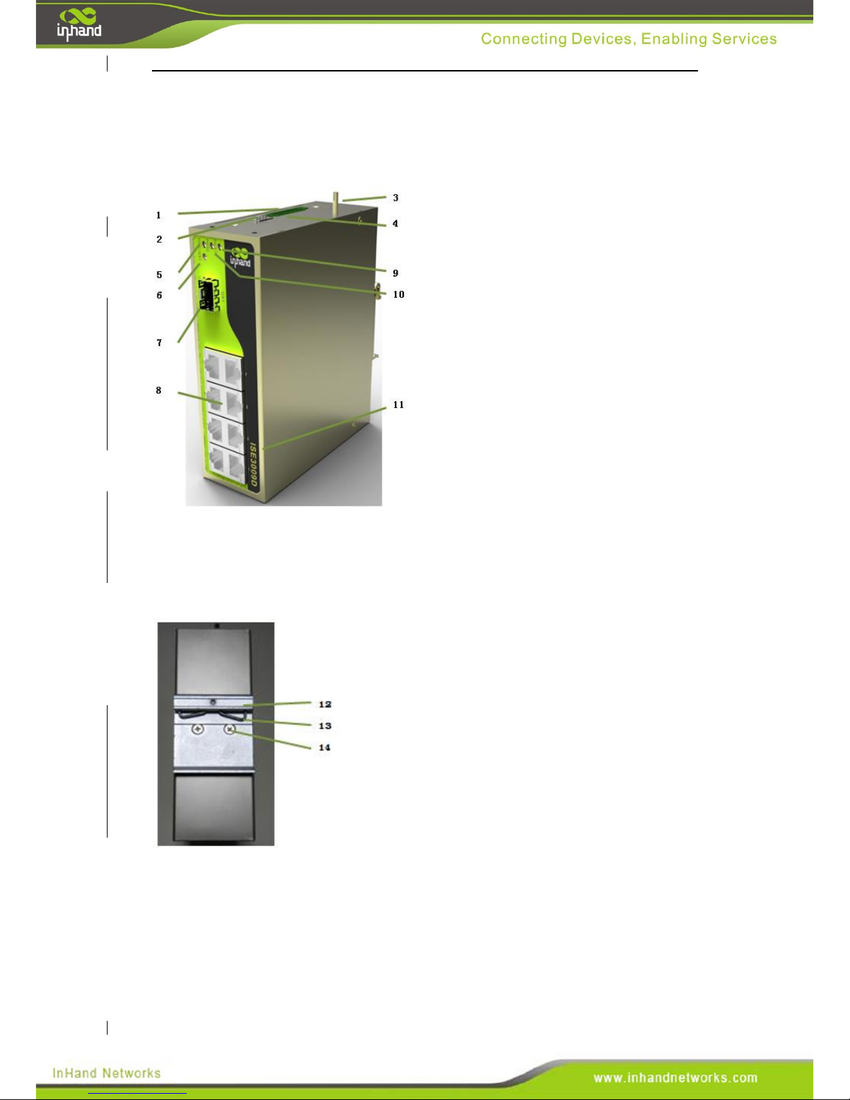
3.5 ISE3009D
Front Panel Layout
1.Power source connection and alarm
connection terminal
2. Dip switch
3. Grounding Screw
4. Cover plate
5. Power source one indication lamp
6. GX1 LINK/ACT indication lamp
7. 1000Base-X, 1000Base-T(X) SFP
port GX1
8. 10/100Base-T(X) RJ45 port
9. Alarm indication lamp
10. Power source two indication lamp
11. InSwitch model number
14. DIN-rail bracket upper lip
15. Clamp spring
16. DIN-rail bracket attachment screw
Page 19
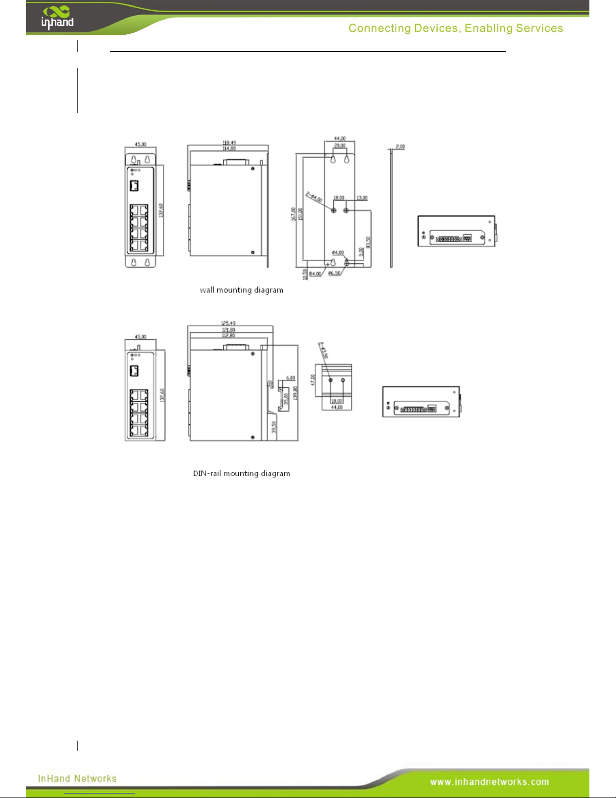
Structural Dimensions
(Units: mm)
Page 20
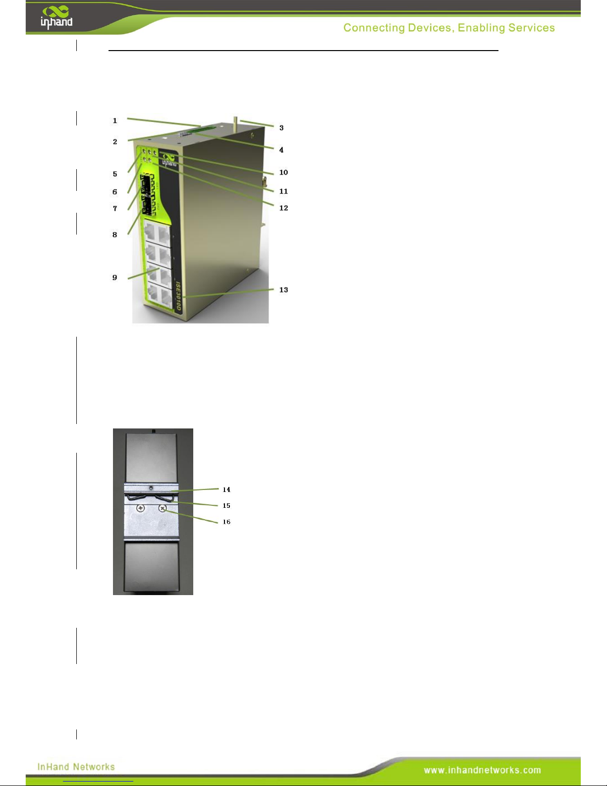
3.6 ISE3010D
Front Panel Layout
1. Power source connection and alarm
connection terminal
2. Dip switch
3. Grounding screw
4. Cover plate
5. Power source one indication lamp
6. GX1 LINK/ACT indication lamp
7.1000Base-X, 1000Base-T(X) SFP
interface GX1
8.1000Base-X, 1000Base-T(X) SFP
interface GX2
9. 10/100Base-T(X) RJ45 port
10. Alarm indication lamp
11. Power source two indication lamp
12. GX2 LINK/ACT indication lamp
13. InSwitch model number
14. DIN-rail bracket upper lip
15. Clamp spring
16. DIN-rail bracket attachment screw
Page 21
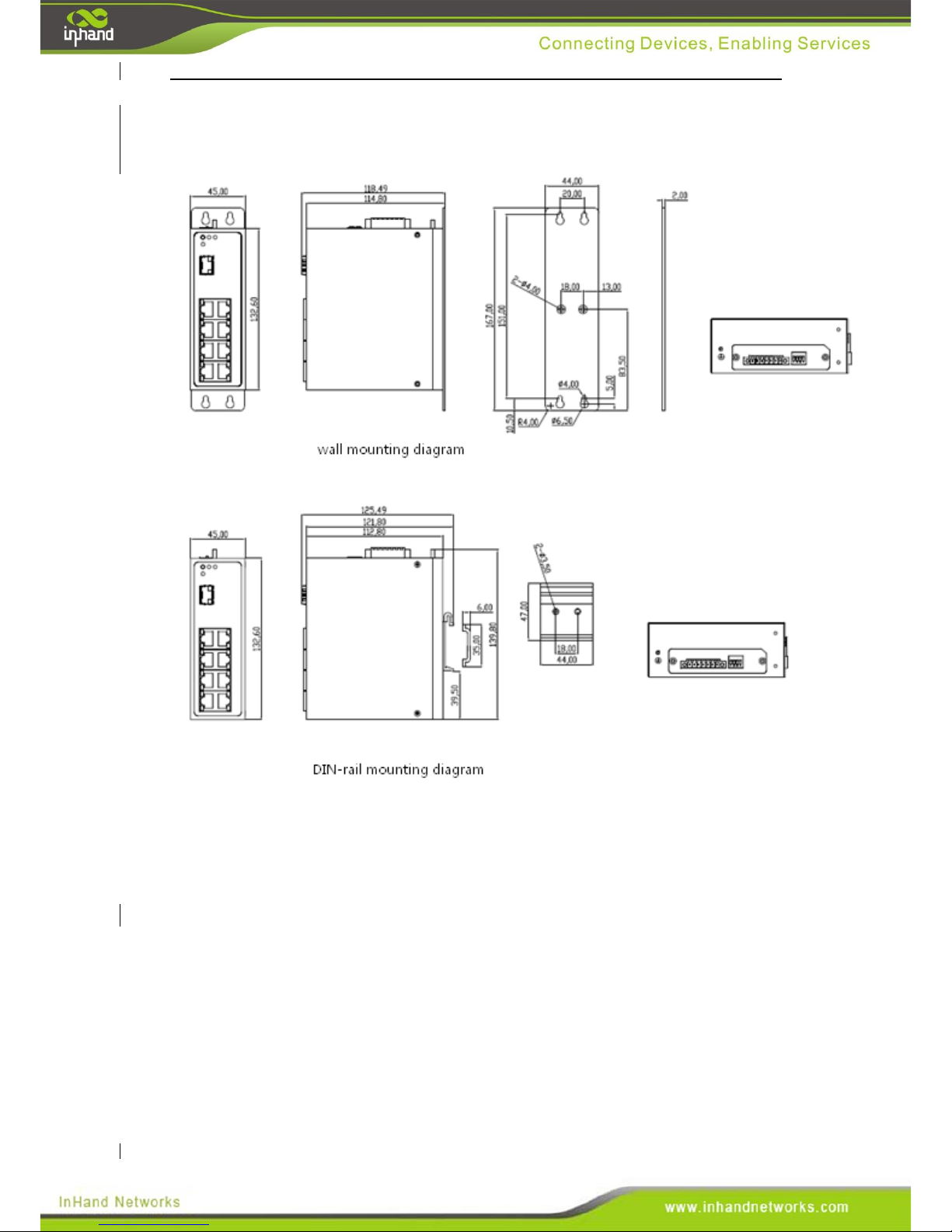
Structural Dimensions
(Units: mm)
Page 22
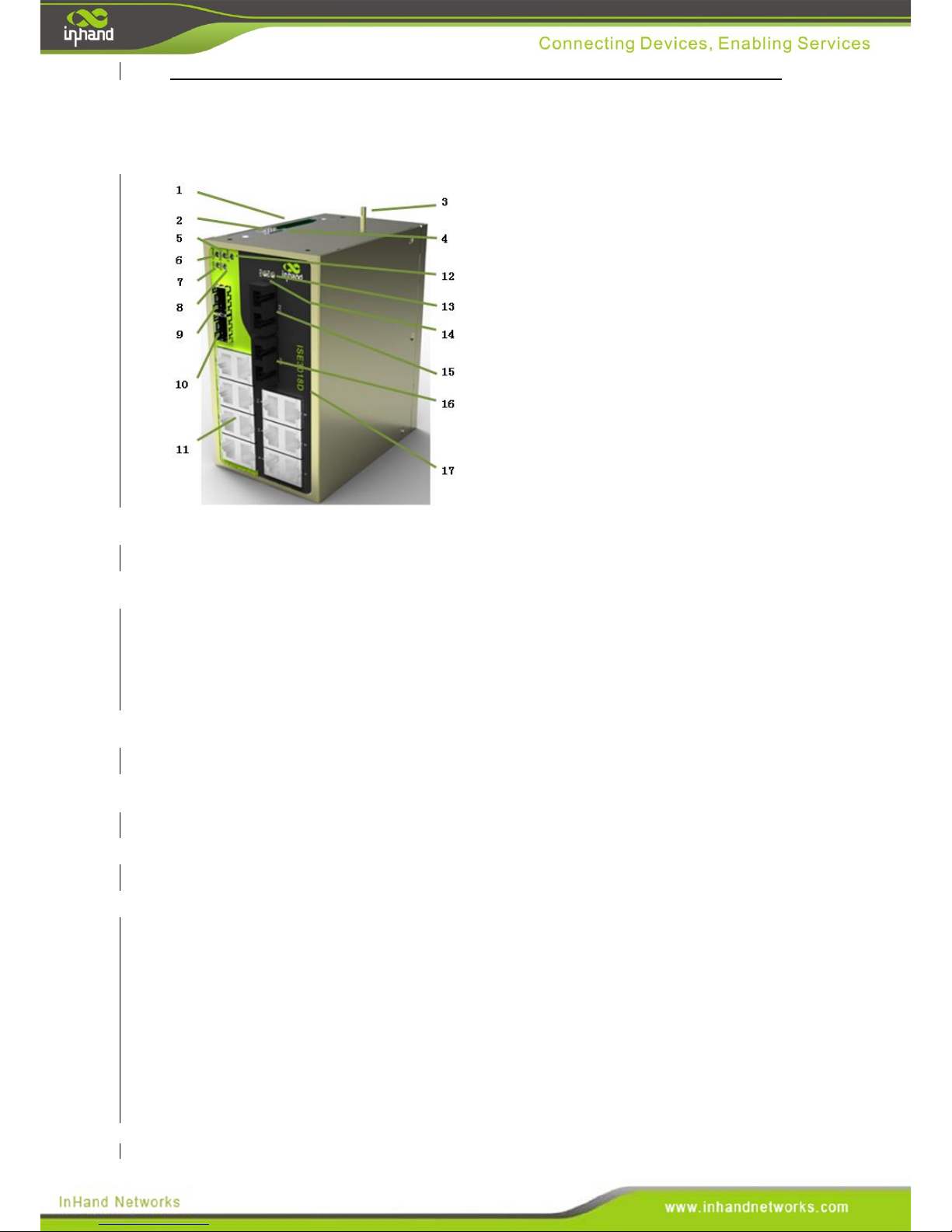
3.7 ISE3018D
Front Panel Layout
1. Power terminal
2. Dip switch
3. Grounding screw
4. Cover plate
5. Power source two indication lamp
6. Power source one indication lamp
7. GX1 LINK/ACT indication lamp
8. GX2 LINK/ACT indication lamp
9.1000Base-X,1000Base-T(X) SFP
interface GX1
10.1000Base-X,1000Base-T(X) SFP
interface GX2
11.10/100Base-T(X) RJ45 port
12. Alarm indication lamp
13. Optical port FX2 LINK/ACT
indication lamp
14.Optical port FX2 LINK/ACT
indication lamp
15.100Base-FX single mode/multimode
FC/SC/ST interface FX1
16.100Base-FX single mode/multimode
FC/SC/ST interface FX2
17. InSwitch model number
Page 23
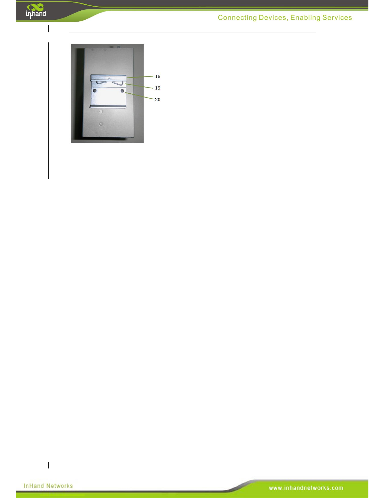
18. DIN-rail bracket upper lip
19. Clamp spring
20. DIN-rail bracket attachment screw
Page 24
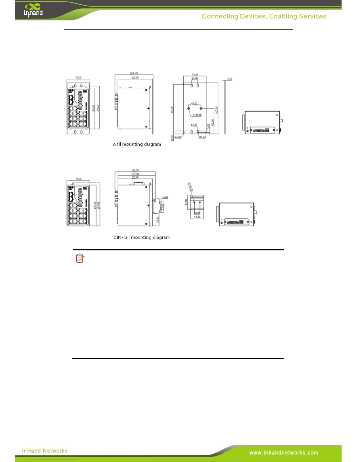
Structural Dimensions
(Units: mm)
Note:
1. Some product models have optional copper and fiber ports. Therefore, one part
number is used as an example in the layout sections. The models have optional
ports:
ISE1005D:1 100M fiber/copper port optional, 4 100baseT(x)
ISE2005D:1 100M fiber/copper port optional, 4 100baseT(x)
ISE2008D:4 100M fiber/copper port optional, 4 100baseT(x)
ISE3008D:1 1000M fiber port, 3 100M fiber port,4 100baseT(x)
ISE3009D:1 1000M fiber port, 8 100baseT(x)
ISE5005D:1 100M fiber/copper port optional, 4 100baseT(x)
Page 25
IV. Installation
Installation Requirement
Power source requirements: 24 VDC (12~48 VDC). Attention shall be paid
to power voltages.
Operating temperature: -40~85 ℃
Storage temperature: -40~85 ℃
Relative humidity 5%~95% (non-condensing).
Grounding resistance requirement: less than 1 Ω.
Avoid direct sunshine and keep away from heat sources or intensive
electromagnetic interference.
Inspect for availability of cable and joints required for installation.
4.1 Instruction for DIN-Rail Installation
4.1.1 DIN-Rail Mounting
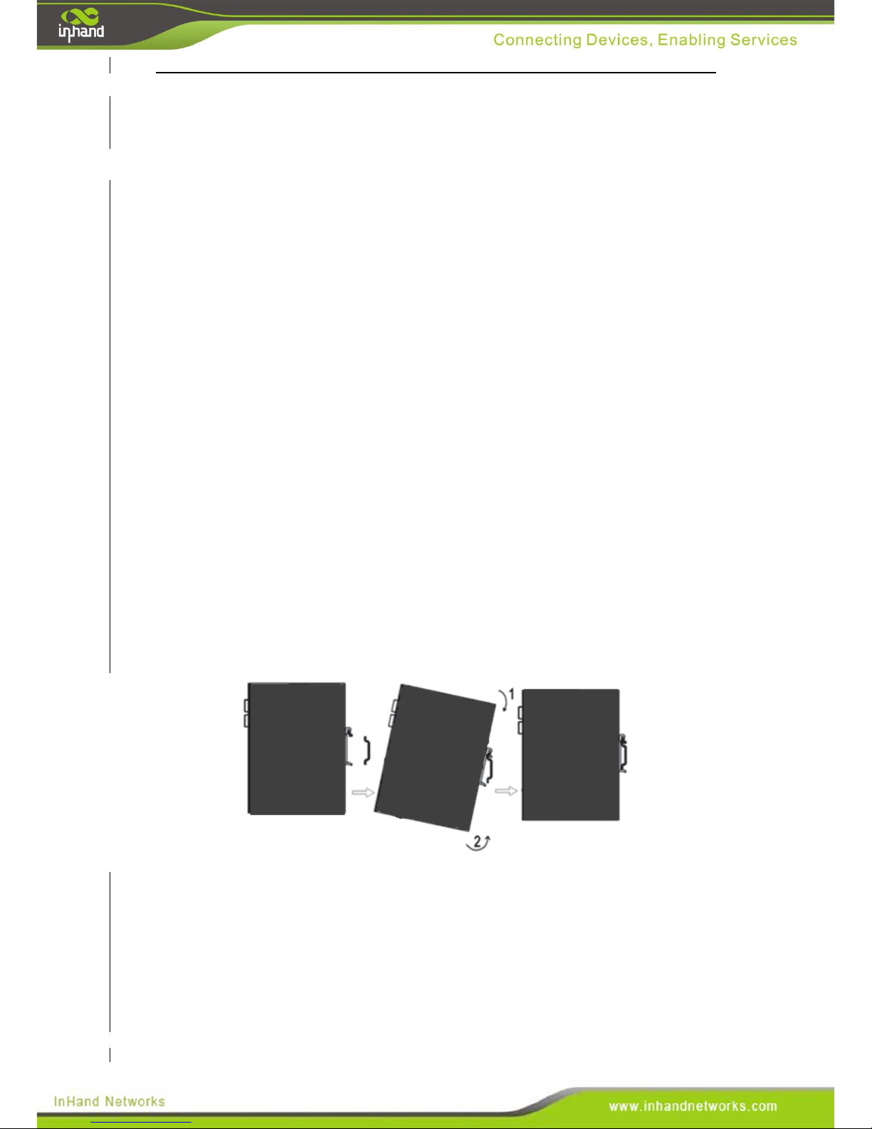
Step 1: Select a place to install the device, and make sure there is sufficient space.
Step 2: Hook the upper lip of the bracket onto the DIN-rail.
Step 3: While pushing down to compress the clips, push the bottom part of the switch
towards the wall.
4.1.2 DIN-Rail Removal
Step 1: As the arrow 1 shows, pull down on the device to compress the bracket clips.
Step 2: Pull the bottom of the device away from the wall until is unsnaps from
the DIN-rail.
Step 3: Unhook the device from the DIN-rail.
Page 26
4.2 Instruction for Wall mounting
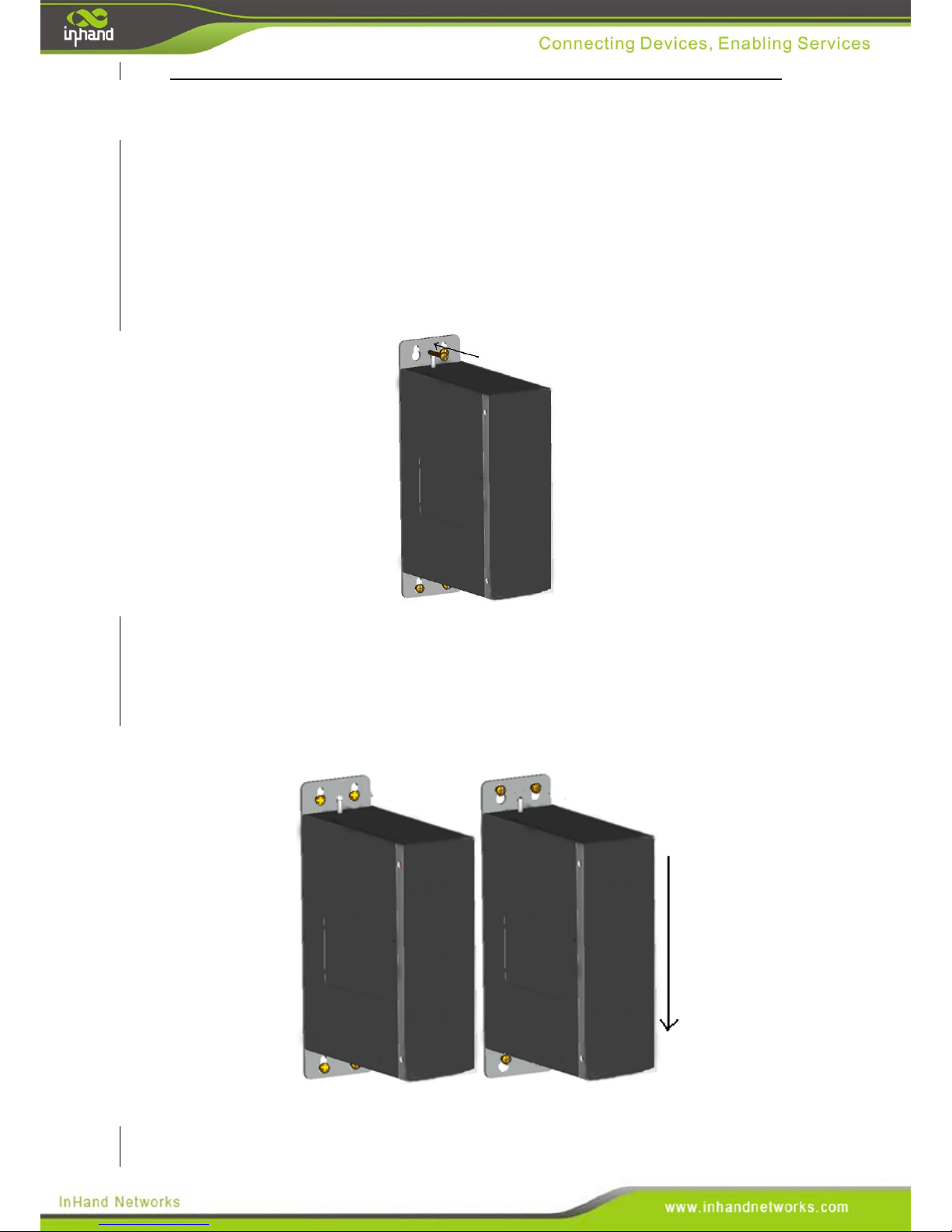
4.2.1 Wall mount
Follow these steps:
Step 1: Install the wall-mounting plate onto the switch.
Step 2: Locate the screws which are packaged with the wall mounting plate. Fix
screws in the mounting position as shown by the arrows in Figure 4-3.
Figure 4-3 Mount the Device on the Wall
Step3: After installing the screws, pull the switch into the position as shown in Figure
4-4.
Figure 4-4
Page 27
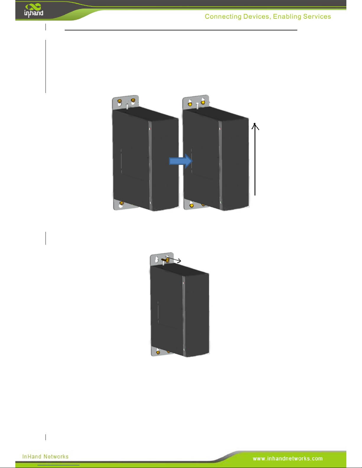
4.2.2 DIN-Rail Dismount
Step1: Use a screwdriver to loosen the screws, so that the switch can freely move up
and down.
Step2: Lift switch to the position shown in Figure 4-5.
Figure 4-5
Step3: Hold the switch up and remove the four screws.
Figure 4-6
Page 28
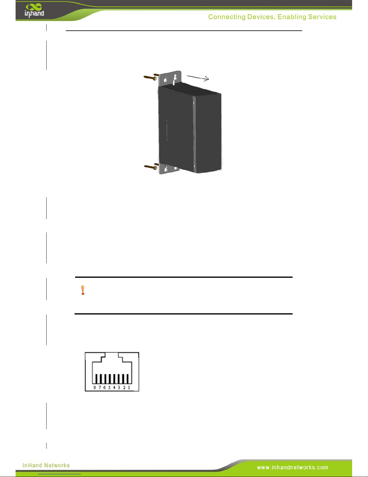
Step 3b: Alternatively, do not remove the screws, and directly remove the switch by
lifting while gently pulling it away from the wall, as shown in figure 4-7.
Figure 4-7
V. Ethernet Cables and Wiring
5.1 10/100Base-T(X) port
The RJ45 interface automatically detects 10/100Base-T(X) and MID/MDI-X
protocols. The RJ-45 ports may be connected with either a straight-through or
crossover cable and can automatically compensate for either type.
Attention: Standard CAT5 or CAT5e types twisted pair cabling shall be
used.
Image of an RJ45 interface
Page 29
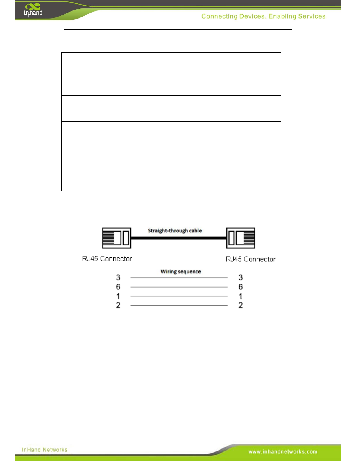
Description of pins on 10/100Base-T(X) port
Pin
MDI
MDI-X
1
Positive terminal for data
transmission(TD+)
Positive terminal for data receiving
(RD+)
2
Negative terminal for data
transmission(TD-)
Negative terminal for data receiving
(RD-)
3
Positive terminal for data
receiving(RD+)
Positive terminal for data transmission
(TD+)
6
Negative terminal for data
receiving(RD-)
Negative terminal for data transmission
(TD-)
4,5,7,8
Not used
Not used
100Base-TX Straight-through cable
Page 30
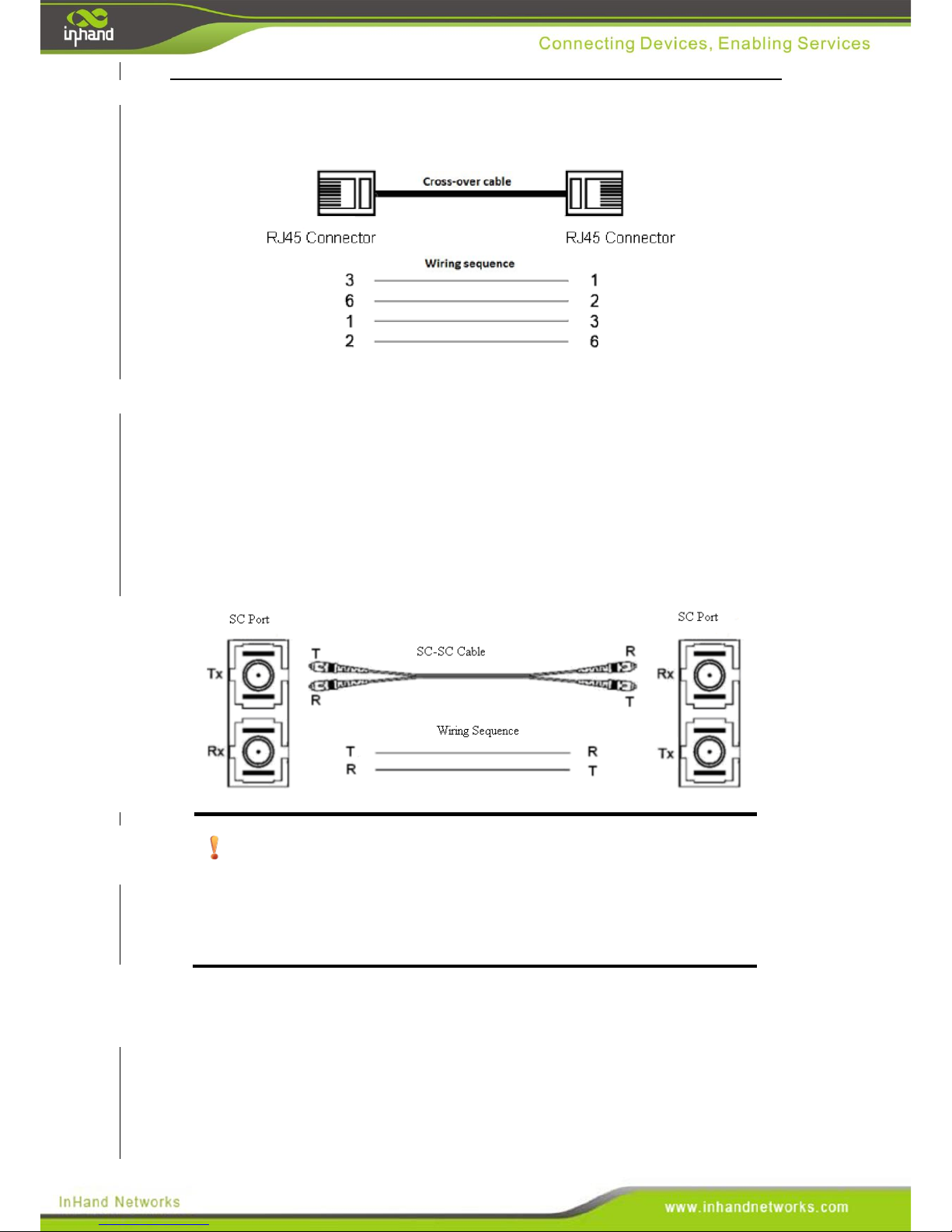
100Base-TX cross-over cable
5.2 100Base-FX port
Carefully plug in the optical cables and polish the connectors if nessecary. Rough
handling and repeated use can damage the cable and connectors.
Ensure that both ends of the fiberoptic cable are correctly wired. The Tx port of the
home terminal shall be connected to Rx port of the opposite terminal, and the Rx of
the home terminal shall be connected to Tx port of the opposite terminal. Here, the SC
port is used as an example for wiring optical cable connections. The process for
connecting ST, FC and LC cables are the same as SC.
Attention:
When both ends of the fiberoptic cable are plugged in, but the port LEDs do
not blink, check that the wiring is correct. The Rx and Tx cables may be
switched.
5.3 1000Base-X, 1000Base-T(X) SFP Port
The SFP port supports either a gigabit SFP optical module (1000Base-X) or gigabit
SFP electric module, 1000Base-T(X), depending on network requirements.
Page 31
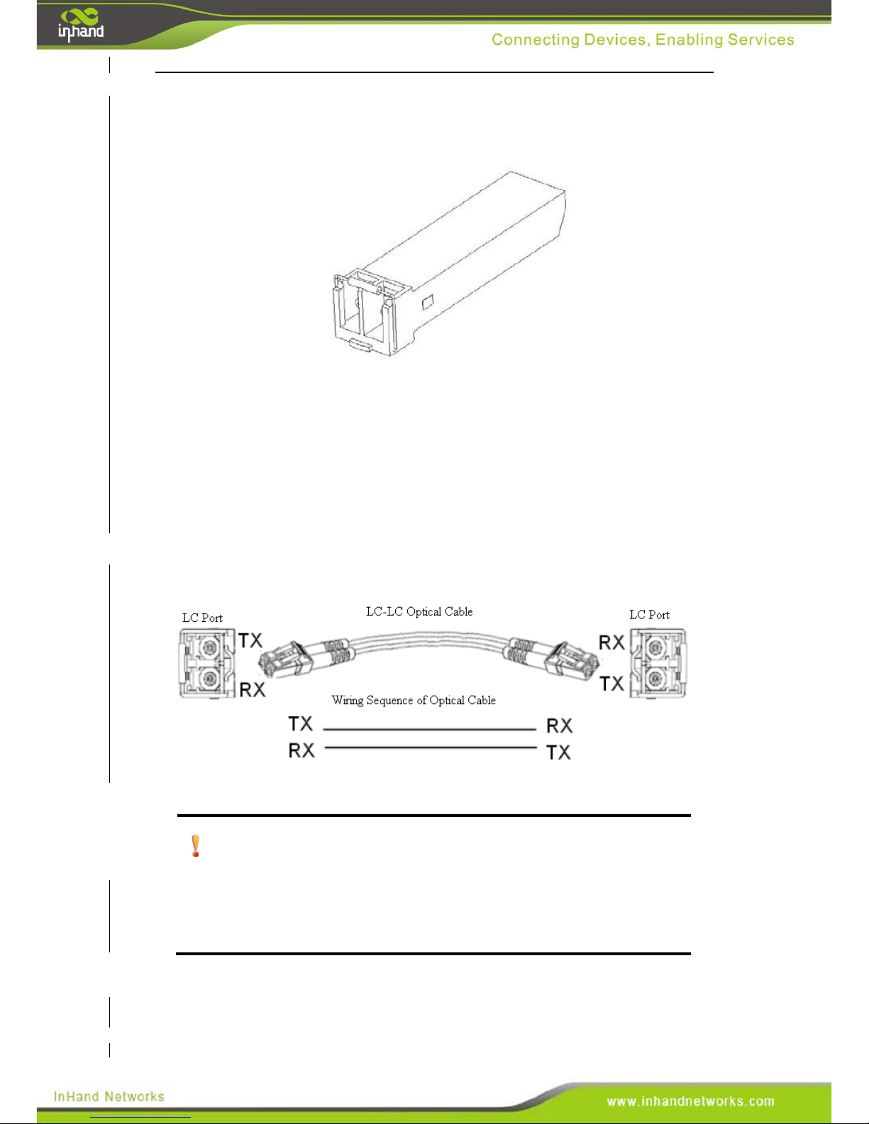
Gigabit SFP optical module
A typical gigabit SFP optical module is shown in the following diagram:
LC interface is adopted for gigabit SFP optical module, including receiving port (Rx)
and transmission port (Tx).
Optical cable connection steps:
Step 1: Plug a SFP optical module into the SFP slot.
Step 2: To onnect an optical cable, connect the Rx of the home port to the Tx of
the opposite port, and connect the Tx of the home port to the Rx of the opposite
port, as shown in the following diagram:
Attention:
When both ends of the fiberoptic cable are plugged in, but the port LEDs do
not blink, check that the wiring is correct. The Rx and Tx cables may be
switched.
Page 32
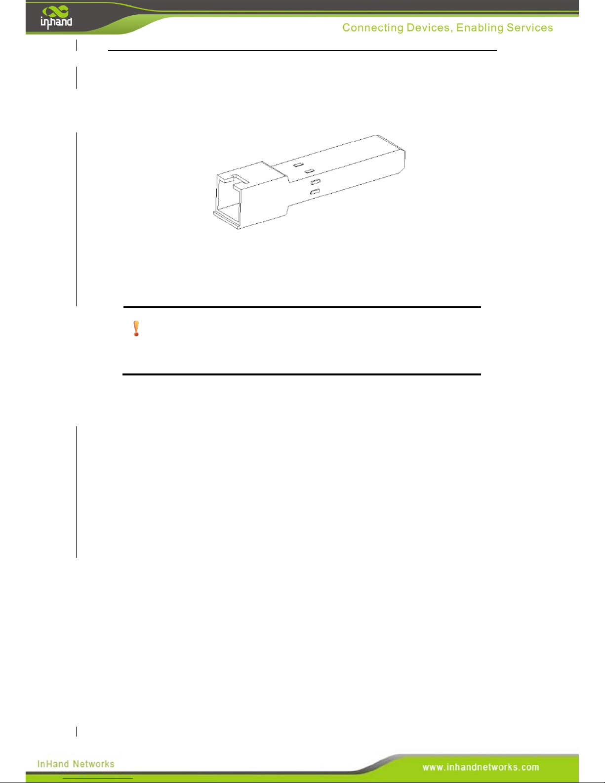
Gigabit SFP electric module
Typical gigabit SFP electric module is shown in the following diagram.
The steps for connecting network cables to an SFP electric module are as follows:
Step 1: Plug the SFP electric module into the SFP slot.
Step 2: Connect both ends with an Ethernet cable.
Attention:
CAT5, CAT6 or CAT7 types of twisted pair cable shall be used.
5.4 Power Source
The InSwitch ISE series allow for dual redundant power supplies on it’s industrial
terminal block. Dual power supply connections allow users to provide more
redundancy and fallback options for important nodes. The terminal block allows
industrial and electric power users to employ the existing power supply in an
enclosure. Simply wire the power supply’s positive negative and ground into the
power terminal to power on the switch.
Page 33
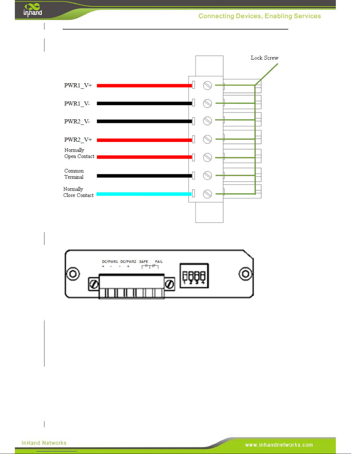
The wiring schematic for the industrial power terminal is shown below.
The terminal block is shown in the following schematic.
Wiring Method:
Step 1: Unplug the terminal-block from the switch.
Step 2: Insert the cables into the terminal before tightening screw.
Step 3: Insert the terminal-block back into the switch before fastening the flange
screws. The method for screwing down the block is shown below.
Page 34
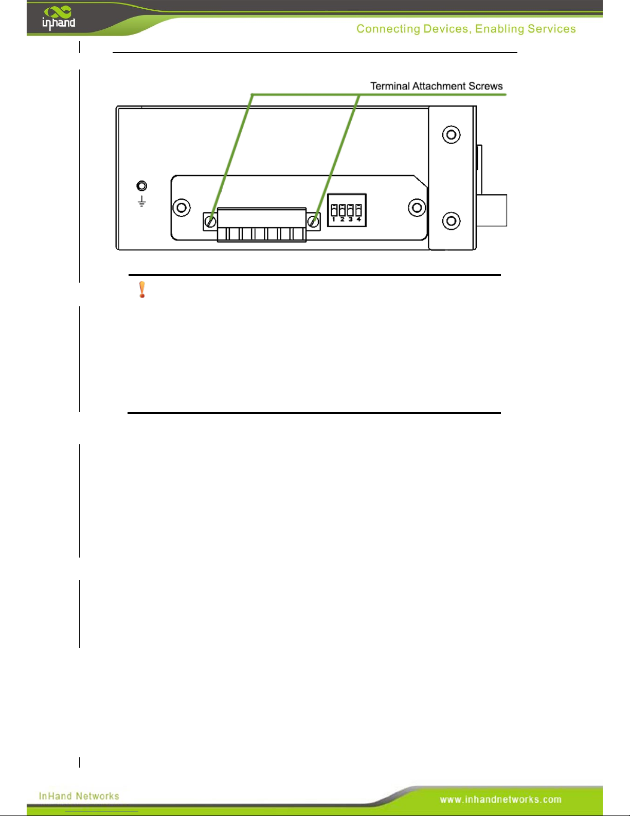
Attention
Power supply wire diameter and torque:
Minimum cross-section of wire, AWG/kcmil 28
Maximum wire cross-section,AWG/kcmil 16
Minimum applied torque, 0.22 Nm
Maximum applied torque, 0.25 Nm
5.5 Grounding Protection
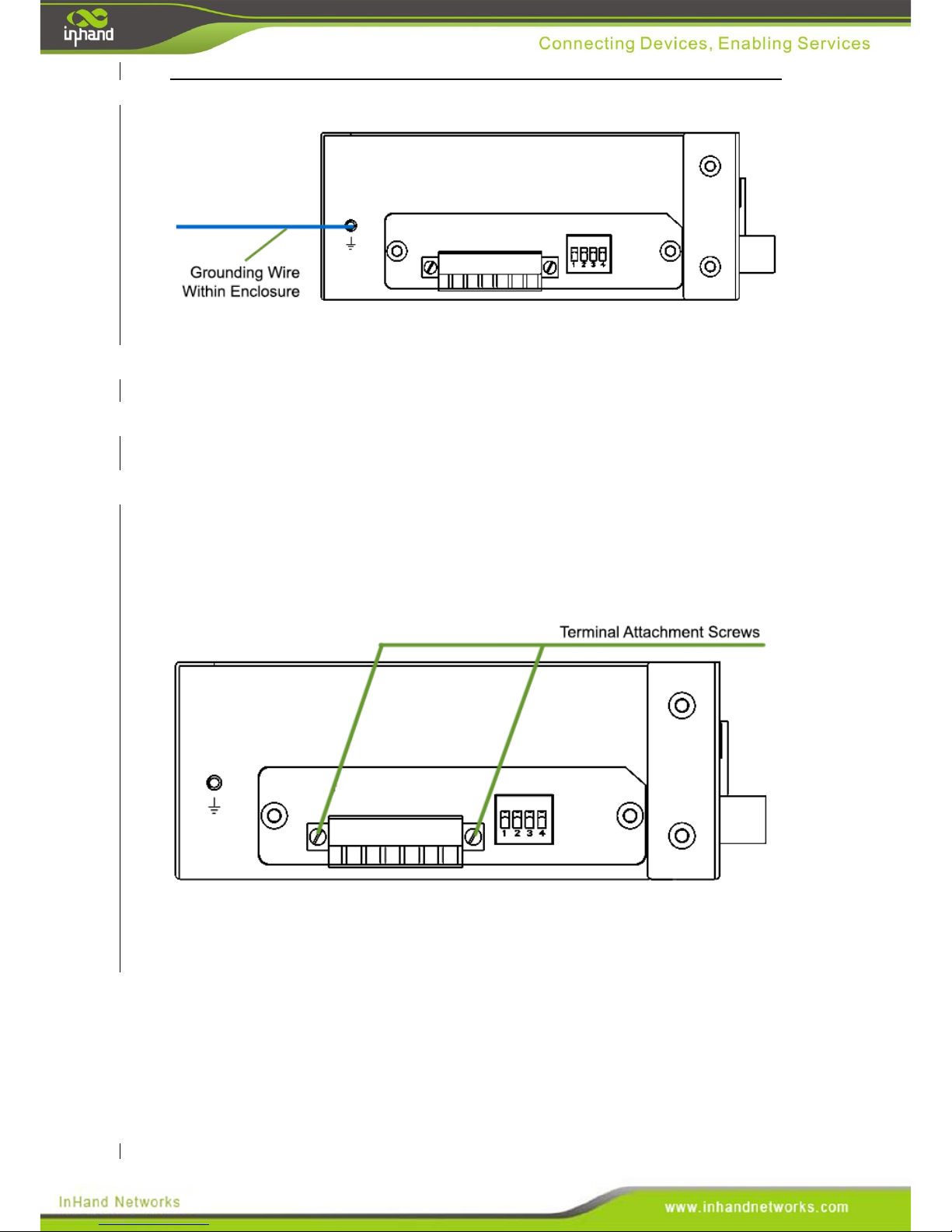
ISE InSwitches have a metal case and grounding screw for protection from electrical
surges, discharges, electrical fields and magnetic fields. To make sure the electrial
protection of the switch is functioning well, connect the grounding screw to an
existing power supply or any designated grounding area.
Wiring Method:
Step 1: Unscrew the grounding screw.
Step 2: Wrap the grounding wire around the screw.
Step 3: Tighten the grounding screw.
Page 35
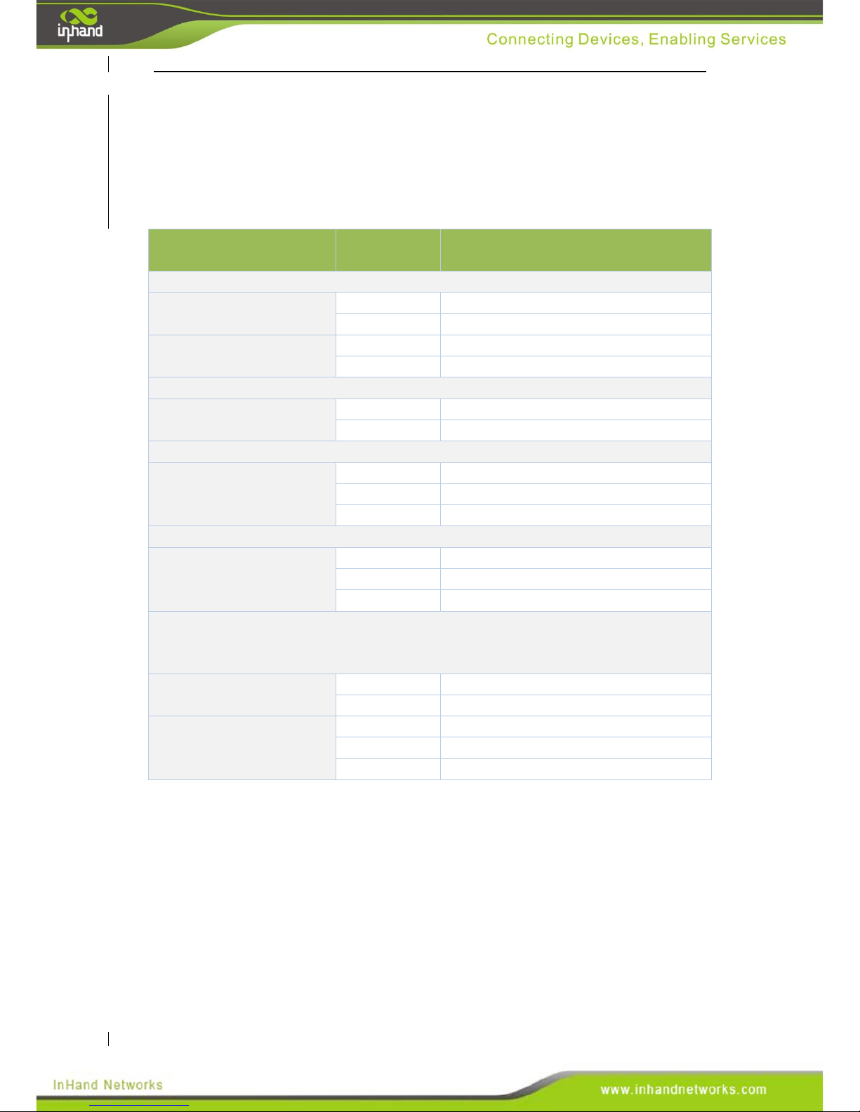
5.6. Alarm
Please refer to chapter 6.3 “Introduction to alarms” for a detailed description of the
alarm function.
Wiring Method:
Step 1: Unplug the terminal-block from the switch.
Step 2: Plug the alarm cable into the terminal before tightening the screw.
Step 3: Plug the terminal into the switch and tighten down the attachment screws.
Step 4: Change the alarm-related dip switch to the desired positions. Please refer to
6.2 “Dip Switch” for more information on the dip switches.
Page 36
VI. Functions and Features
6.1 LED Indicator Codes
A variety of LED indicators are located on the front panel of the switch. Please see the
table below for definitions on each indicator.
Name of Indication
Lamp
Lamp State
ISE Equipment State
Power source indication lamp
PWR1
On
Connection of power source 1 normal
Off
Connection of power source 1 failure
PWR2
On
Connection of power source 2 normal
Off
Connection of power source 2 failure
Alarm indication lamp
FAULT
On
Switch equipment in alarm state
Off
Switch equipment in normal state
1000Base-X,1000Base-T(X) indicator lamp
GX1
…
GXn
On
Port connected
Flash
Data passing through
Off
Interruption of port connection
100Base-FX indicator lamp
FX1
…
FXn
On
Port connected
Flash
Data passing through
Off
Interruption of port connection
10/100Base-T(X) indicator lamp
Each 10/100Base-T(X) RJ45 interface is provided with a red lamp and a green lamp.
The red lamp indicates port rate, and the green lamp indicates port connection state.
Red lamp
On
Port connected
Off
Interruption of port connection
Green lamp
On
Optical port connected
Flash
Data passing through
Off
Interruption of port connection
Page 37
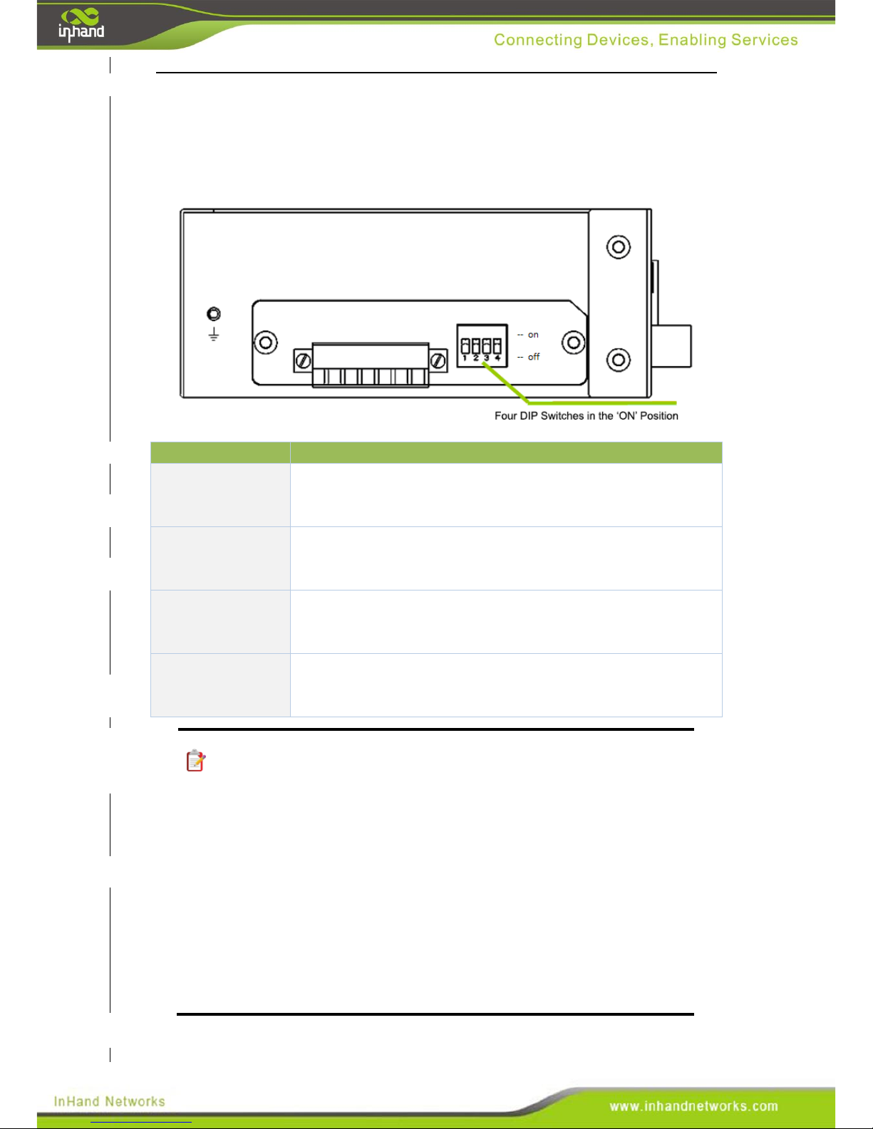
6.2. Dip Switches
There are four DIP switches located on the top panel of the InSwitch. Each DIP switch has either
an ON or OFF state, controlling one of the switches functions. In the following diagram, all of the
switches are in the ON state.
Dip Switch
Corresponding Functions
Switch 1
Connection disruption alarm for optical port one
OFF = Disabled
ON = Enabled
Switch 2
Connection interruption alarm for optical port two
OFF = Disabled
ON = Enabled
Switch 3
Broadcast storm control function
OFF = Broadcast storm control disabled
ON = Broadcast storm control enabled
Switch 4
Flow control
OFF = Flow control disabled
ON = Flow control enabled
Note:
For type ISE2XXX products, switches one and two corresponds to
alarms for disrupted connections on FX1 and FX2 respectively. If the
FX2 port is not included on your model number, then dip-switch 2 is not
used.
For type ISE3XXX products, position 1 and 2 corresponds to alarm
for disrupted connections on GX1 and GX2 respectively. If the GX2
portis not included on your model number, then dip-switch 2 is not used.
If an optical port is not included on your specific model, then both
switches one and two are not used.
Page 38
6.3 Introduction to Alarms
Two abnormal events are defined for ISE series products: loss of connection and
power supply failure. Either of these events will trigger an alarm.
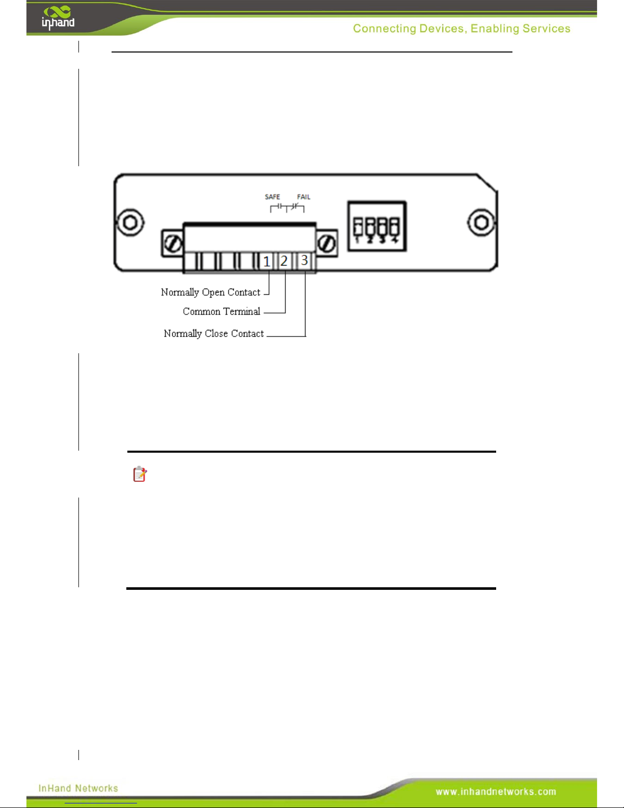
The relay is provided with three contacts: open by default, closed by default and one
common terminal. The ports are shown in the following diagram.
When the switch is in a normal operational state, the two ports corresponding to
SAFE will become a closed circuit (switched on), and the two ports corresponding to
FAIL will become an open circuit (switched off) state. When the switch is not
powered on or undergoing an abnormal operation status, the two ports corresponding
to SAFE will be an open circuit (switched off), and the two ports corresponding to
FAIL will be a closed circuit (switched on). Alarm output: 2A@30VDC.
Note:
Port connectivity interruption alarms can be enabled or disabled via the
dip switch, but the main power source fault alarm is always enabled.
When an alarm event occurs, a triggered relay will maintain the alarm
state. The relay will return to a normal state only after all alarm events
have been corrected.
Page 39
VII. Specifications
The specifications of the ISE industrial Ethernet switch are given in the following
table.
System Index
Parameter Introduction
Switching properties
Supports IEEE802.3 and IEEE 802.3u
Switching mode: Store-and-forward mode
Inherent time delay for forwarding: under 4 µs
Electromagnetic
compatibility
IEC 61000-4-2 (static electricity), class 3
IEC 61000-4-3 (radiating electric filed), class 3
IEC 61000-4-4 (pulse packet), class 3
IEC 61000-4-5 (surge), class 3
IEC 61000-4-6 (conducted emission), class 3
IEC 61000-4-8 (power frequency magnetic filed), class 4
Power source
Input voltage: 24VDC (12~48VDC) redundant input s
Alarm relay output
Maximum voltage 220 VDC
Maximum current 2A
Maximum switching power 60W
Mechanical properties
Physical dimensions:
Size of narrow body type: 45mm×132.6mm×112mm
(W×H×D)
Size of wide body type: 75mm×132.6mm×112mm
(W×H×D)
Housing material: Galvanized corrosion resistant steel
Housing surface treatment: Powder coating
Installation mode: Industrial rail clamps and wall mounting
options
Heat dissipation mode: Fanless heat dissipation
Protection class: IP40
Impact: IEC60068-2-27
Vibration: IEC60068-2-6
Free falling: IEC60068-2-32
Weight:
Narrow body type: <0.6kg
Wide body type: <0.9kg
Working environment
Working temperature: -40 ~ 85 ℃
Storage temperature: -40 ~ 85℃.
Humidity: 5%~95% (free of condensation)
MTBF
35 years
Warranty period
5 years
Page 40
VIII. Networking Mode
8.1 Networking of Single Set of Equipment
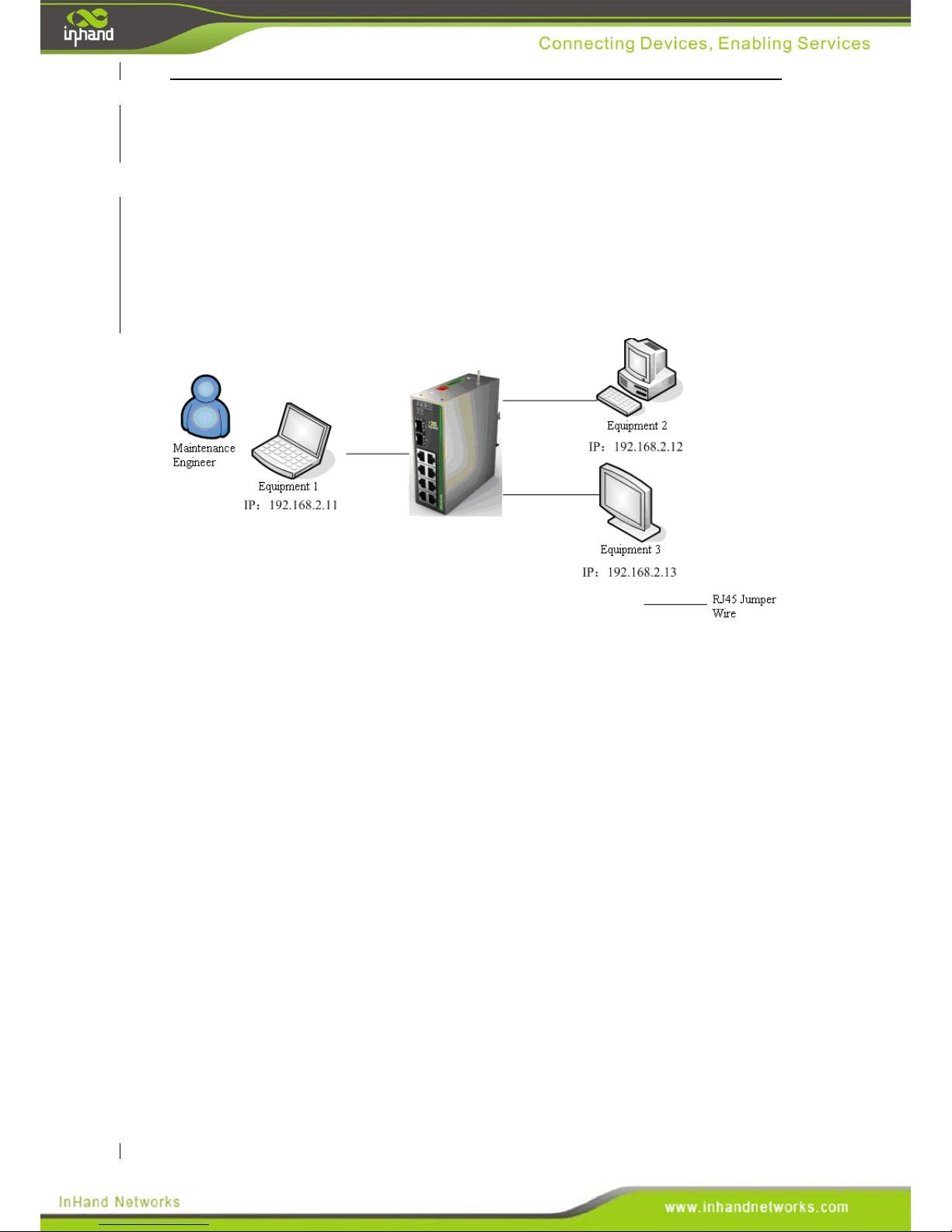
To communicate between device one, two and three, connect them all to the switch
and configure the correct IP addresses. All device on a single switching network must
share the same subnet of IP addresses, for instance 192.168.2.x/24. X can be any
value from 1 to 255. An example topology is shown below:
Page 41
8.2 Networking of Multiple Sets of Equipment
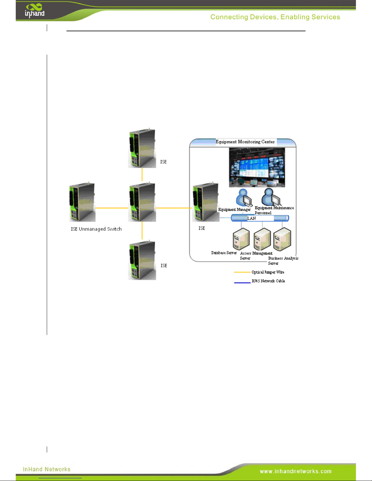
InSwitch ISE industrial Ethernet switch provides 10/100Base-T(X) Ethernet RJ45
ports or 100Base-FX or 1000Base-GX fiber ports for connecting switches and
devices.Each port may be connected to a device or another switch. The InSwitch ISE
industrial Ethernet switch have 100Base-FX(1000Base-GX optional ) single
mode/multimode fiber ports for compatibility with fiber optic cables. Fiber optic rings
are widely used in Elecric power, transportation, energy, water treatment and
industrial automatic control. A networking example is shown below:
Page 42
IX. Appendix
Appendix One: Glossary of Terms
Abbreviation
Full English Name
Meaning
100Base-TX
100Base-TX
100 Mbps baseband Ethernet specification uses
two pairs of category 5 twisted-pair cables.
They can provide a maximum transmission rate
of 100Mbits per second.
10Base-T
10Base-T
10Mbps baseband Ethernet specification uses
two pairs of twisted-pair (category 3/4/5
twisted pair) connections, one of which will be
used for sending data and the other for
receiving data, They support a maximum
transmission rate of 10Mbits per second.
DDNS
Dynamic Domain
Name
Service
Dynamic Domain Name Service can assign and
retrieve the domain name of a dynamic, public
IP address.
DHCP
Dynamic Host
Configuration
Protocol
Dynamic Host Configuration Protocol
dynamically assigns the IP addresses, subnet
mask, gateway and other information to hosts
on a network.
DNS
Domain Name
Service
Domain Name Service resolves a domain name
into an IP address. DNS information is
distributed hierarchically between DNS servers
throughout the Internet. When we visit
a website, DNS server views the domain name
sending the request and searches for the
corresponding IP address. If the DNS server
can not find the IP address, it will submit the
request to the superior DNS server and
continue to search for the IP address. For
example, the IP address corresponding to the
domain name www.yahoo.com is
216.115.108.243.
Firewall
Firewall
A firewall protects your computer or local area
network from malicious attacks from internet.
Page 43
MAC
address
Media Access
Control address
A Media Access Control address is the
permanent physical address assigned by the
manufacturer to the device. It is composed of 6
pairs of hexadecimal digits. For example:
00-0F-E2-80-65-25. Each network device has a
global unique 48-bit MAC address.
NAT
Network
Address
Translation
Network Address Translation allow multiple
hosts to access the internet on a single public IP
address. Without NAT, only one host may be
assigned a public IP. NAT also helps protect
the local network from external threats.
Ping
Packet Internet
Grope
Ping tests connectivity from a host to a remote
host using ICMP packets. It is a very common
and easy tool to use.
QoS
Quality of
Service
Quality of Service is a technology used to solve
the problems of network delay and obstruction.
In case of network overload or congestion, QoS
can ensure that important traffic will not be
delayed or discarded, while ensuring efficient
operation of network.
RJ-45
RJ-45
Standard plug for connecting Ethernet
switches, hubs, routers, and other devices.
Straight-through cable and crossover cable may
be used with this interface.
Route
Route
A router routes packets between networks
based on an IP address. A route is the path
between those two networks. Routing is a
layer-three only, while local networks are
layer-two only.
SNMP
Simple Network
Management
Protocol
SNMP is a protocol for remote management of
device on the network. It defines a series of
messages, methods and syntax used to achieve
remote management.
TCP
Transfer
Control
Protocol
Transfer Control Protocol is a
connection-oriented and reliable transport layer
protocol.
TCP/IP
Transmission
Control
Protocol/Internet
Protocol
Transmission Control Protocol/Internet
Protocol is the cluster of basic communication
protocols for network communication. TCP / IP
defines a set of protocols, including not only
TCP and IP.
Telnet
Telnet
A character-based interactive program used to
access a remote host. Telnet allows the user to
remotely login and manage the device.
Page 44
UDP
User Datagram
Protocol
User Datagram Protocol is a non-connection
oriented based transport layer protocol.
WAN
Wide Area
Network
Wide Area Network is a data communication
network covering a relatively wide
geographical scope, e.g. the Internet.
LAN
Local Area
Network
Local Area Network generally refers to the
internal network like a home network or
internal network of a business.
Appendix Two: Important Safety Information
This product is not intended for use in the following circumstances
Area(s) where radio transmission equipment (such as cell phone) are not
permitted.
Hospitals, health care facilities and area(s) where cell phones are restricted by
law.
Gas stations, fuel storage and places where chemical are stored.
Chemical plants or places with potential explosion hazard.
Any metal surface that may weaken the radio signal level.
RF safety distance
For GPRS router, the compliance boundary distance is r=0.26m for GSM
900MHz and r=0.13m for DCS 1800 MHz.
For HSUPA router, the compliance boundary distance is r=0.26m for GSM
900MHz and
r=0.13m for DCS 1800 MHz, r=.0.094 for WCDMA 900MHz, r=0.063 for
WCDMA 2100MHz.
Warning
This is a class A product. In a domestic environment this product may cause
radio interference in which case the user may be required to take adequate
measures.
WEEE Notice
The Directive on Waste Electrical and Electronic Equipment (WEEE), which
entered into force as European law on 13th February 2003, resulted in a major
change in the treatment of electrical equipment at end-of-life.
The purpose of this Directive is, as a first priority, the prevention of WEEE,
and in addition, to promote the reuse, recycling and other forms of recovery of
such wastes so as to reduce disposal.
Page 45

The WEEE logo (shown at the left) on the product or on its box indicates that
this product must not be disposed of or dumped with your other
household waste. You are liable to dispose of all your electronic or
electrical waste equipment by relocating over to the specified collection point
for recycling of such hazardous waste. Isolated collection and proper recovery
of your electronic and electrical waste equipment at the time of disposal will
allow us to help conserving natural resources. Moreover, proper recycling of
the electronic and electrical waste equipment will ensure safety of human
health and environment.
For more information about electronic and electrical waste equipment disposal,
recovery, and collection points, please contact your local city centre,
household waste disposal service, shop from where you purchased the
equipment, or manufacturer of the equipment.
 Loading...