

Page 1

1 / 92
IG601 Intelligent Gateway
User Manual
InHand Networks
www.inhandnetworks.com
Version: v2.4
September 2017
Copyright © 2016. All rights are reserved by InHand Networks and its licensors. Without the written
permission of the Company, no unit or individual is allowed to excerpt, reproduce or transmit in any
form part or all of the contents in the manual.
Page 2

2 / 92
INHAND and InHand are trademarks of InHand Networks. The trademarks of other
companies, product logos and trade names in the manual are possessed by their respective owners.
The contents of this manual may be changed due to product version upgrade or other reasons. InHand
reserves the right to modify the contents of this manual without any notice or prompt. This manual is
only used as the guidance. InHand makes every effort to provide accurate information in this manual,
but InHand does not guarantee that there is no error in the manual. All statements, information and
recommendations in this manual do not constitute any express or implied warranty.
Page 3
3 / 92
Preface
Welcome to the IG601 series industrial gateway user manual. This manual will guide you on how to
configure the IG601.
This preface includes the following contents:
Intended Users
Conventions in the Manual
Obtaining Documentation
Technical Support
Feedback
Intended Users
This manual is intended for the following users:
Network architects
On-site technical support
Network administrators
Any other network staff
Conventions in the Manual
To help guide the reader, the manual will use the following conventions.
Format
Description
< >
Content in angle brackets “< >” indicates a button name. For example, the <OK>
button.
“”
“” indicates a window name or menu name. For example, the pop-up window “New
User.”
>>
A multi-level menu is separated by the double brackets “ >>.” For example, the
multi-level menu File >> New >>Folder indicates the menu item [Folder] under the
sub-menu [New], which is under the menu [File].
Various Signs
The manual also uses a variety of eye-catching signs to indicate the places where special attention
should be paid. The significances of these signs are as follows:
Attention indicates something very important. Improper operation may
cause data loss or damage to the device.
Page 4
4 / 92
Detailed description of certain features.
Obtaining Documentation
The latest product information is available on the InHand website, www.inhandnetworks.com .
Specific documentation can be found in these areas:
Support >> Technical Support: Product information on hardware installation, software upgrade,
configuration, manuals and more are available.
Products >> Industrial Intelligent >> IG601: An introduction to the Intelligent Gateway, along
with manuals, data sheets, a quick guide, and other support documentation. Other products can be
found by browsing through the products menu.
Support >> Software Download: Software updates, webinars and technical papers are available
for download.
Technical Support
InHand is invested in supporting our products with fast and reliable customer service. Feel free to email.
E-mail: [email protected]
Website: www.inhandnetworks.com
Feedback
If you have any comments or questions on your products, please send us feedback via email.
E-mail:[email protected]
Your feedback is vital to improving our products.
Page 5

5 / 92
Contents
Preface ................................................................................................................................................. 3
IG601 Introduction ............................................................................................................................ 7
1.1 Overview ................................................................................................................................ 7
1.2 Product Features ..................................................................................................................... 7
Login Gateway ................................................................................................................................... 9
2.1 Establish Network Connection ................................................................................................ 9
2.1.1 Automatic acquisition of IP address .............................................................................. 9
2.1.2 Set a static IP address ................................................................................................. 12
2.2 Test the network connection between the supervisory PC and InGateway. ............................ 13
2.3 Disconnect from the Proxy Server. ........................................................................................ 15
Web Configuration ........................................................................................................................... 17
3.1 Login the Web Configuration Page of Gateway .................................................................... 18
3.2 System .................................................................................................................................. 19
3.2.1 Basic Setup ................................................................................................................ 20
3.2.2 Time .......................................................................................................................... 20
3.2.3 Serial Port .................................................................................................................. 21
3.2.4 Admin Access ............................................................................................................ 22
3.2.5 System Log ................................................................................................................ 25
3.2.6 Config Management ................................................................................................... 26
3.2.7 System Upgrade ......................................................................................................... 28
3.2.8 Reboot ....................................................................................................................... 29
3.2.9 Logout ....................................................................................................................... 29
3.3 Network ............................................................................................................................... 30
3.3.1 Dialup/Cellular Connection ........................................................................................ 30
3.3.2 LAN .......................................................................................................................... 34
3.3.3 DNS ........................................................................................................................... 35
3.3.4 DDNS ........................................................................................................................ 36
3.3.5 Static Routes .............................................................................................................. 38
3.4 Service ................................................................................................................................. 39
3.4.1 DHCP Service ............................................................................................................ 39
3.4.2 DNS Relay ................................................................................................................. 40
3.4.3 VRRP: Virtual Router Redundancy Protocol .............................................................. 41
3.4.4 Device Manager ......................................................................................................... 42
3.4.5 DTU .......................................................................................................................... 44
3.4.6 Modbus to SMS ......................................................................................................... 46
3.4.7 SMS Alarm Rules ...................................................................................................... 48
3.4.8 Mbsms Variable Template .......................................................................................... 53
3.4.9 SMS ........................................................................................................................... 53
3.5 Firewall ................................................................................................................................ 54
3.5.1 Basic .......................................................................................................................... 54
3.5.2 Filtering ..................................................................................................................... 55
3.5.3 Port Mapping ............................................................................................................. 56
3.5.4 Virtual IP Mapping ..................................................................................................... 57
Page 6

6 / 92
3.5.5 DMZ (All Port Mapping) ........................................................................................... 58
3.5.6 MAC-IP Bundling ...................................................................................................... 59
3.6 QoS ...................................................................................................................................... 60
3.6.1 Bandwidth Control ..................................................................................................... 60
3.6.2 IP Bandwidth Limit .................................................................................................... 61
3.7 Tools .................................................................................................................................... 62
3.7.1 Ping ........................................................................................................................... 62
3.7.2 Trace Route ................................................................................................................ 63
3.7.3 Link Speed Test ......................................................................................................... 64
3.8 Status ................................................................................................................................... 65
3.8.1 System ....................................................................................................................... 65
3.8.2 Modem ...................................................................................................................... 66
3.8.3 Network Connections ................................................................................................. 67
3.8.4 Route Table ................................................................................................................ 68
3.8.5 Device List ................................................................................................................ 69
3.8.6 Modbus PLC .............................................................................................................. 69
3.8.7 Log ............................................................................................................................ 69
3.9 VPN ..................................................................................................................................... 70
3.9.1 IPSec ......................................................................................................................... 71
3.9.2 GRE Tunnels ............................................................................................................. 74
3.9.3 L2TP Client ............................................................................................................... 75
3.9.4 PPTP Client ............................................................................................................... 76
3.9.5 OpenVPN .................................................................................................................. 77
3.9.6 Certificate Management ............................................................................................. 79
4. Applications .................................................................................................................................. 81
Appendix I FAQ ............................................................................................................................... 82
Appendix II Command Lines .......................................................................................................... 84
Appendix III Description of LED .................................................................................................... 91
Page 7

7 / 92
IG601 Introduction
This chapter includes the following parts:
Overview
Product Features
1.1 Overview
The InGateway601 (IG601) combines 3G networks, intelligent protocol conversion, and VPN
technology to create a product designed for remote maintenance and management. The IG601 features
remote communication between the controller and data center, which provides an ingress (or gateway)
for the remote diagnosis and maintenance of the machines. The controller technicians can construct
large-scale networks for remote maintenance of equipment. The IG601 can also be employed as a
communication gateway for equipment to coordinate with each other.
With the IG601, technicians in the office can remotely program field PLCs, monitor variables and
receive alerts in real time. The IG601 supports both communications via the PLCs Ethernet port and
via the serial port. IG601 also supports status queries, PLC controls and alarm message via SMS. The
IG601 series utilizes the ubiquitous cellular network to the fullest and opens new horizons in remote
management and machine to machine communication.
1.2 Product Features
Designed for the Communication of Industrial Equipment
SMS Function:
SMS Alarm: users can receive timely alarm message when PLC exception occur in field.
SMS Check and Control: users can remotely monitor and control PLC.
PLC Collaboration: PLCs can communicate with each other via SMS, ensuring more PLCs
work collaboratively.
Remote Maintenance
Users can achieve PLC’s remote programming via secure channel (serial/Ethernet pot)
Remote Monitoring:
Page 8

8 / 92
IG601 can check real-time operating status (variable) and send it to data center regularly
through 3G/2G network. Users can check PLC’s operation and alarm messages anywhere via
internet.
Industrial Design
In the aspects of EMC, anti-static grade, anti-surge level and wide temperature range, IG601
meet the requirements of industrial and operate easily under harsh environments.
Metal enclosure. IP30.
All EMC grade reach level 3.
Ethernet port supports 1.5kv isolation transformer protection
Serial port support 15kv ESD protection.
Wide temperature range: -30℃~70℃.
Wide voltage range: DC: 12-24V.
Complete Security
Data Transmission Security
InGateway 601 uses encrypted channel to communicate with remote controller, enabling the
process of updating PLC program enjoys high level of encryption, which is comparable to
that of the financial industry.
Network Protection Security
With powerful firewall features, InGateway601 supports SPI State Inspection, Secure Shell
(SSH), Intrusion Protection, DDoS Defense, Attack Defense, IP-MAC binding, etc, protecting
the equipment against external network attack.
Equipment Management Security
Multi-level authorization security mechanism realizes centralized authentication and authorization
management of equipment.
Page 9
9 / 92
Login Gateway
This chapter covers the following:
Establish Network Connection
Test the connection between supervisory PC and InGateway
Cancel the Proxy Server
2.1 Establish Network Connection
2.1.1 Automatic acquisition of IP address
Please set the supervisory PC to “automatic acquisition of IP address” and “automatic acquisition of
DNS server address,” which is the default configuration of Windows. This way, the InGateway
automatically assign an IP address to the supervisory PC using DHCP.
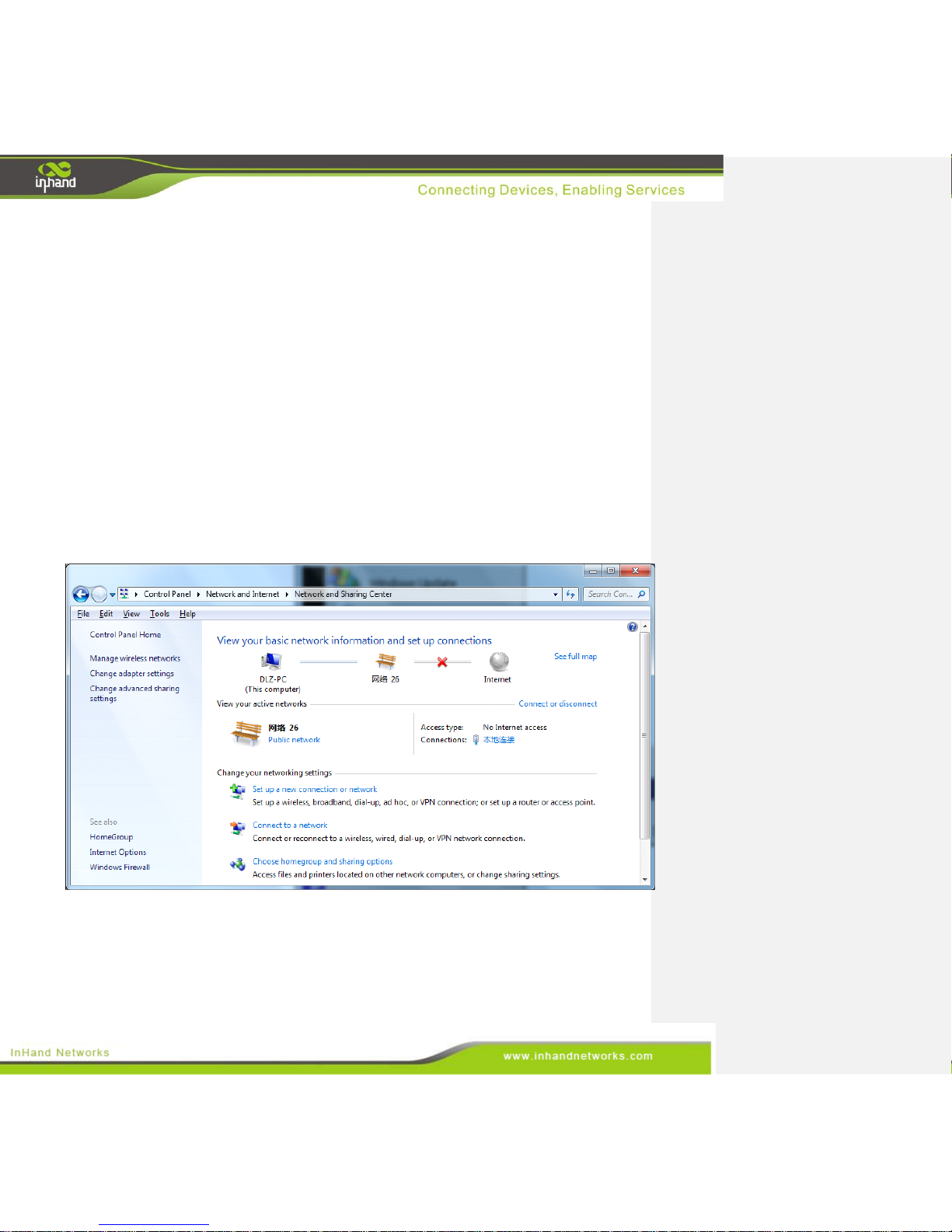
Open “Control Panel”, double click “Network and Internet” icon, and enter “Network and Sharing
Centers”
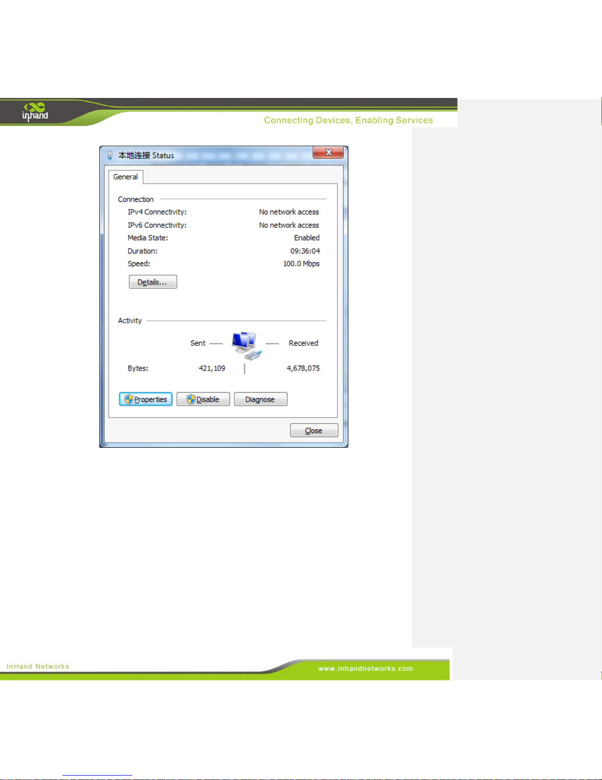
Click the button <Local Connection> to enter the window “Local Connection Status”
Page 10
10 / 92
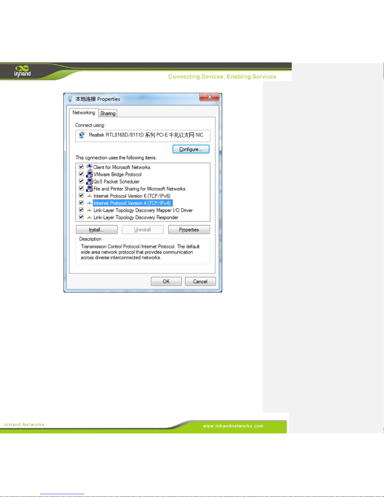
Click <Properties> to enter the window “Local Connection Properties”, as shown below.
Page 11
11 / 92
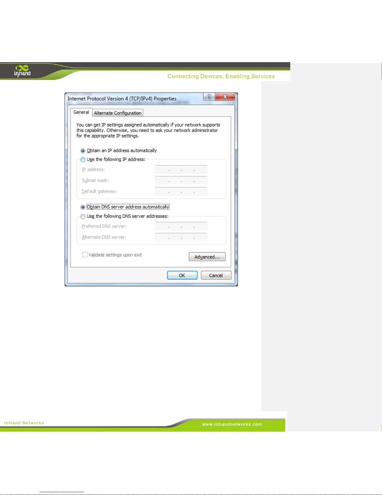
Select “Internet Protocol Version 4 (TCP/IPv4).” Click <Properties> to enter “Internet
Protocol Version 4(TCP/IPv4) Properties.” Select “Obtain an IP address automatically”
and “Obtain DNS Server address automatically,” then click <OK> to complete the process,
as shown below.
Page 12
12 / 92
2.1.2 Set a static IP address
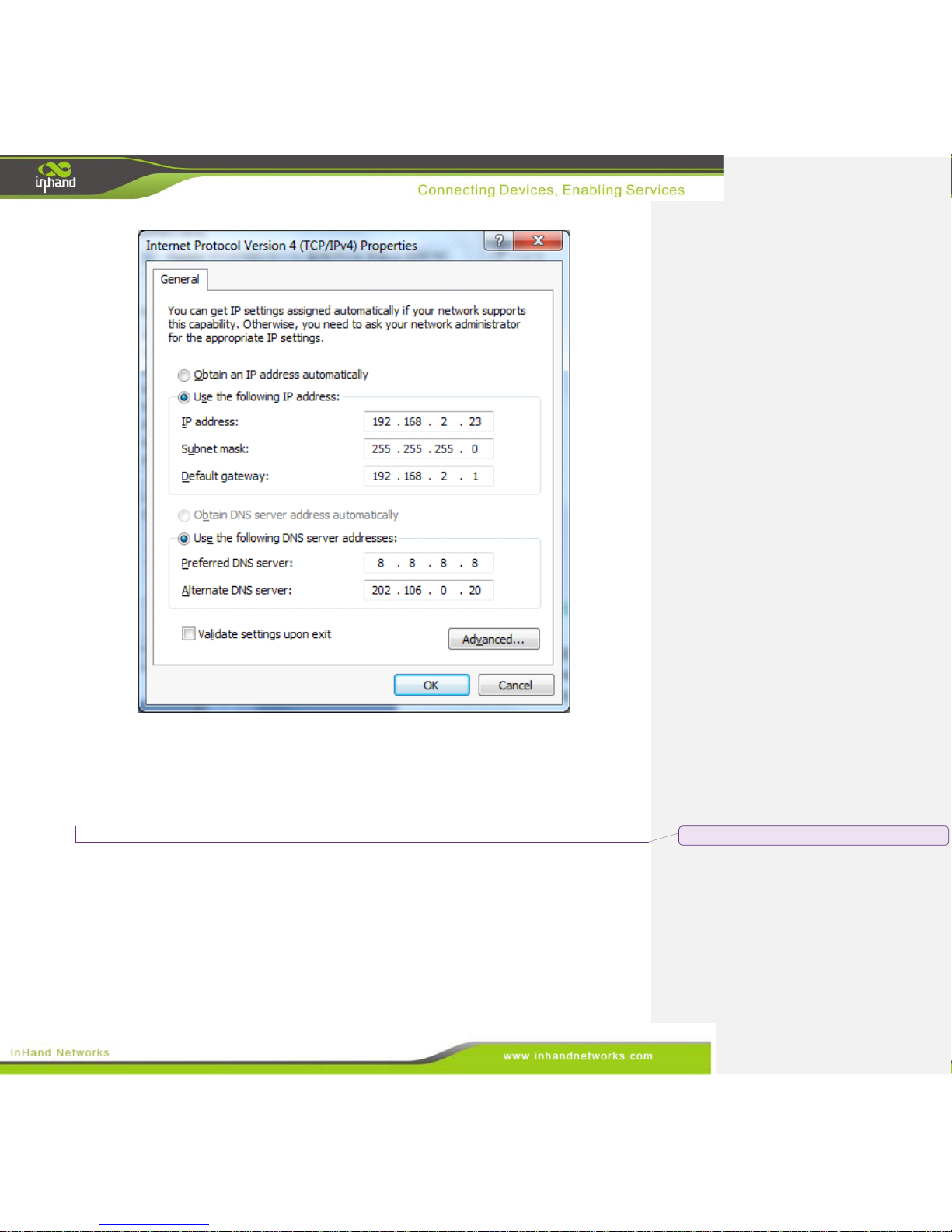
Please set the supervisory PC’s IP address in the same subnet as the gateway FE (or fast Ethernet) port.
In this example, the default IP address of gateway FE port is 192.168.2.1, and the subnet mask is
255.255.255.0. Enter the “Internet Protocol Version 4 (TCP/IPv4) Properties” window. Then,
select “Use the following IP address”, type the IP address (arbitrary value between 192.168.2.2 -
192.168.2.254), subnet mask (255.255.255.0), and default gateway (192.168.2.1) into the text boxes.
Finally, click <OK> to finish setting a static IP, as shown below.
Page 13
13 / 92
2.2 Test the network connection between the supervisory PC and
InGateway.
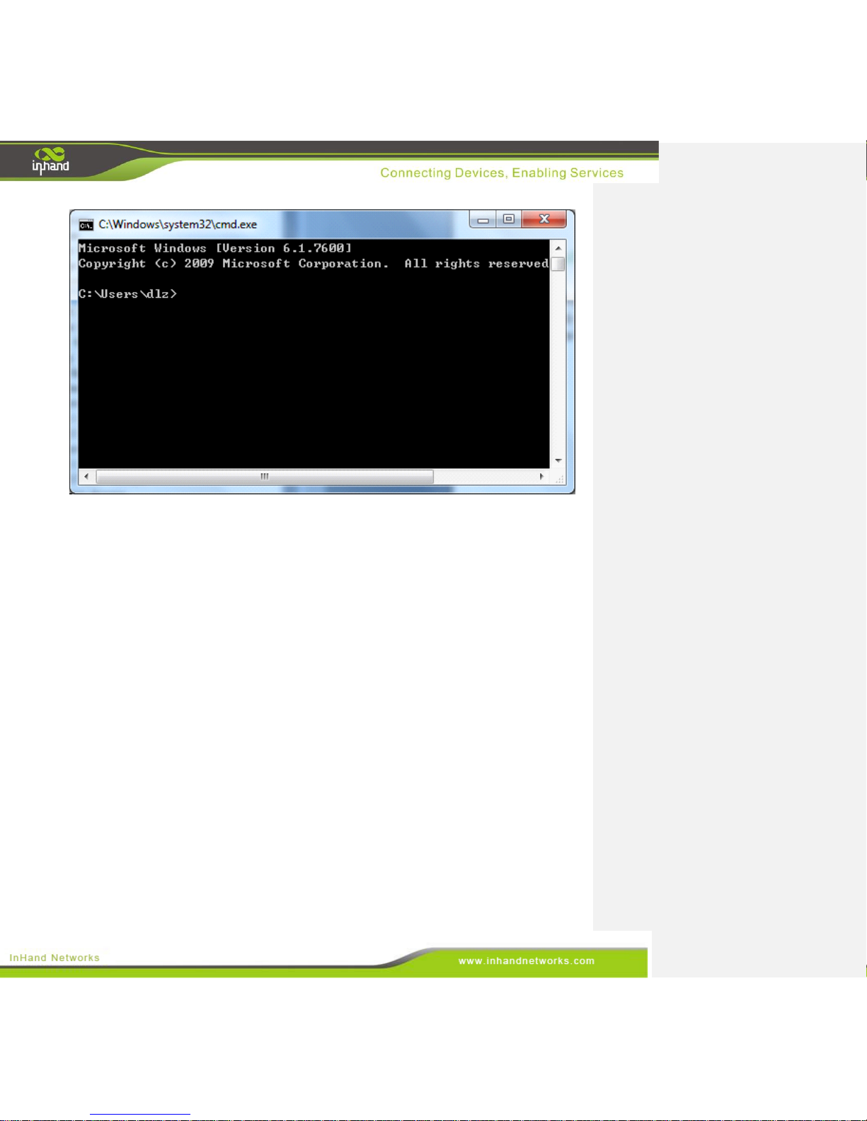
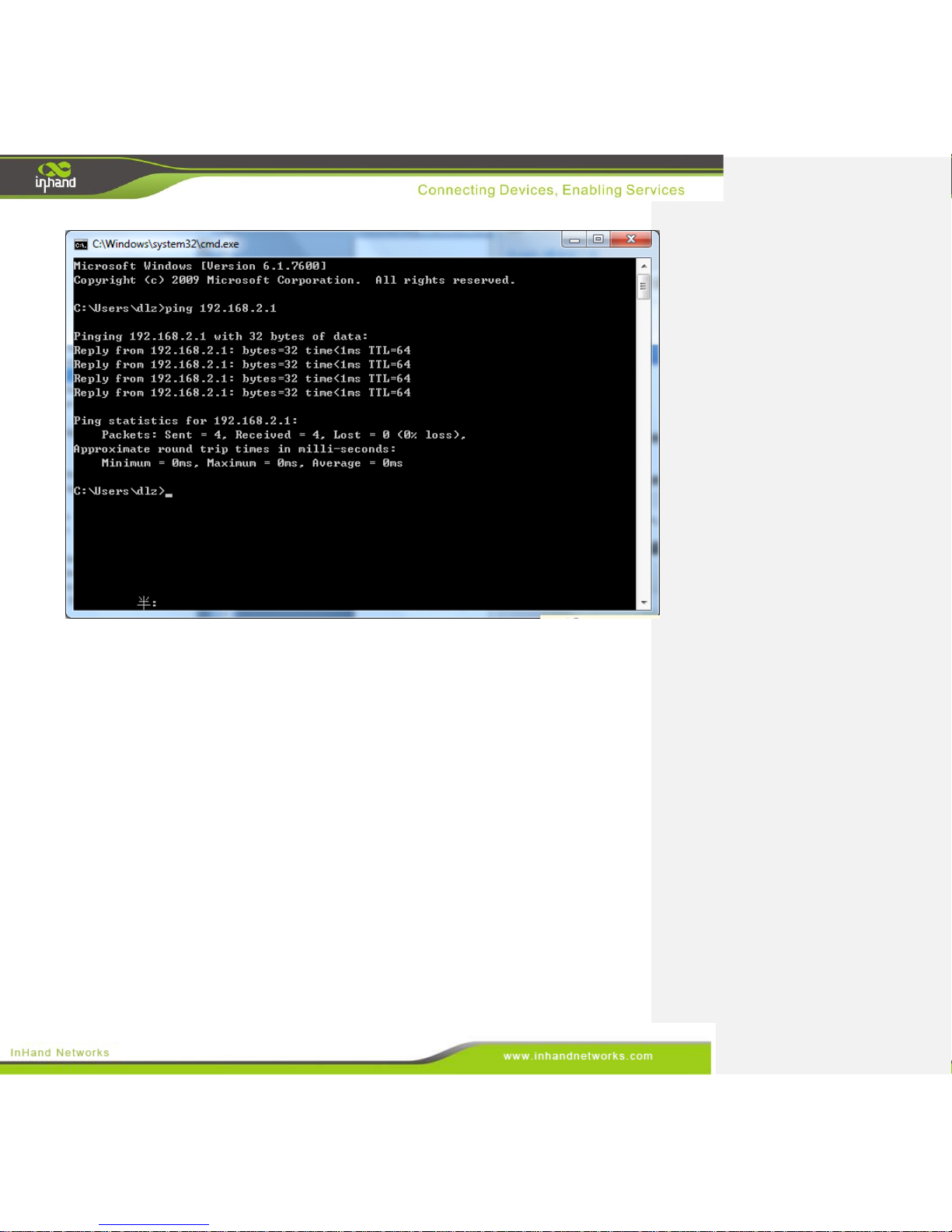
1) Click the button <Start> at the lower left corner. Type “cmd” into the field, and run cmd.exe.
批注 [Unknown A1]: More inconsistent font.
Page 14
14 / 92
2) Enter “ping 192.168.2.1” and click the <OK> button. (192.168.2.1 is the default IP address of the
InGateway). If the connection is good, you will see four returned packets. If there is no response,
be sure to check your connection and your supervisory PC's network settings.
Page 15
15 / 92
2.3 Disconnect from the Proxy Server.
If the supervisory PC uses a proxy server to access the Internet, it is necessary to disconnect from the
proxy and remove any proxy settings. The operating steps are as follows:
Open Internet Explorer.
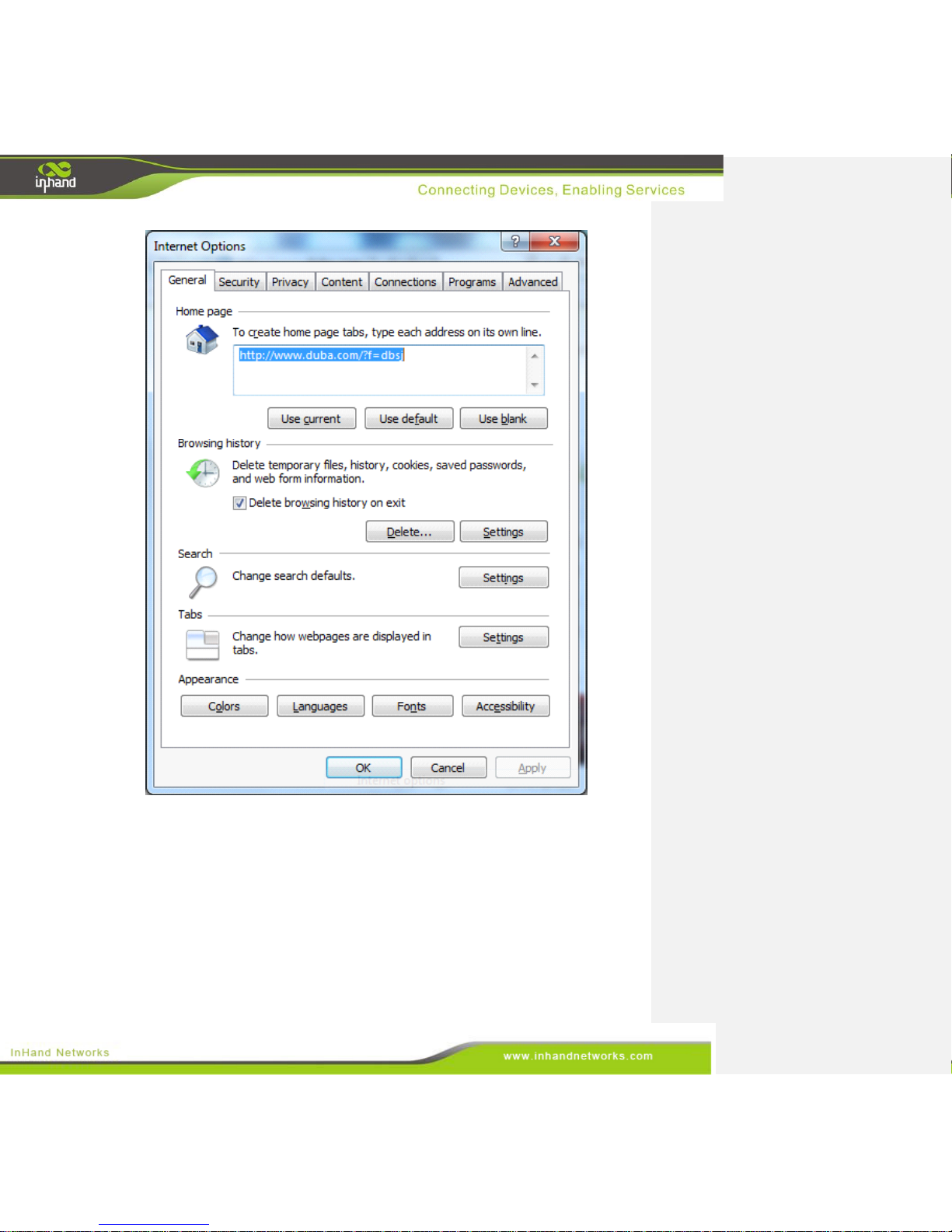
Select Tools>>Internet Options to enter the window “Internet Options”.
Page 16
16 / 92
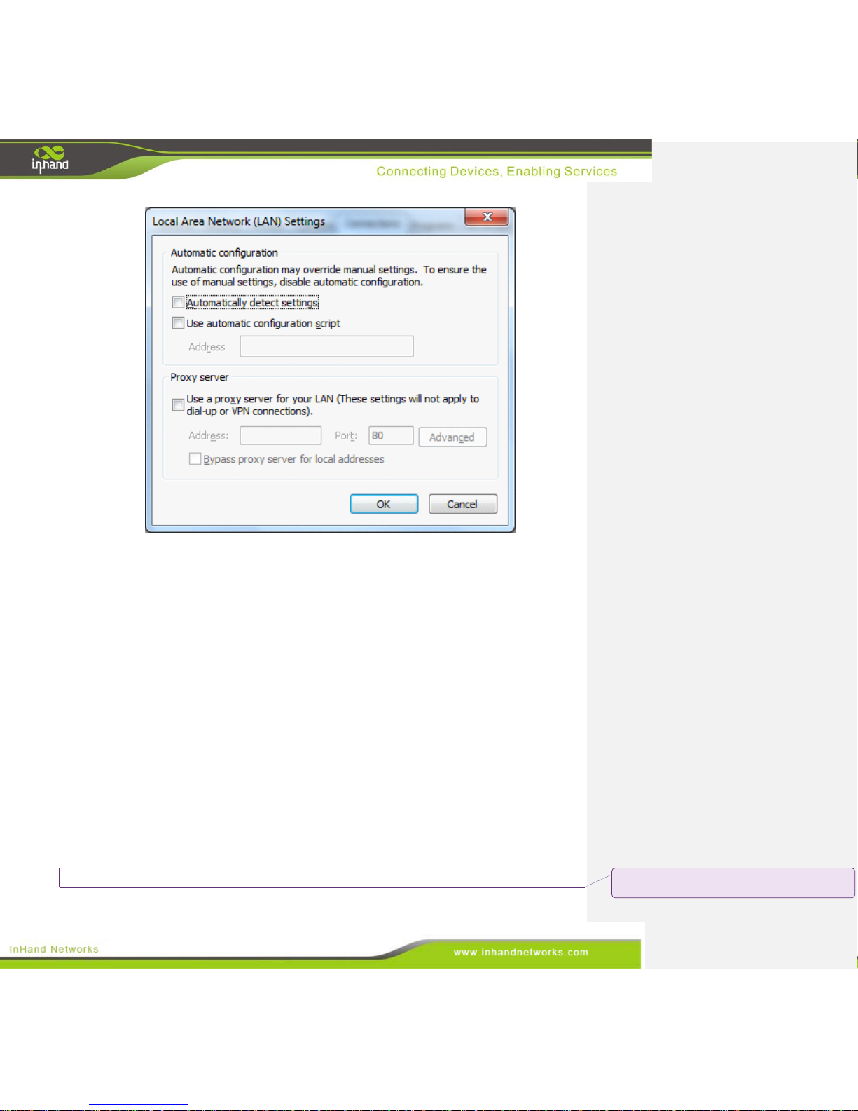
Select the tab “Connect” and click the button <LAN Setting(L)> to enter the window “LAN
Setting.” If the option “Use a Proxy Server for LAN” is checked, uncheck it. Click the <OK>
button and continue to the web configuration section of the manual.
Page 17
17 / 92
Web Configuration
This chapter covers the following contents:
批注 [Unknown A2]: This section seems like it has been
localized already. It only needed light editing.
Page 18
18 / 92
Logging in the Browser Interface
System
Network
Service
Firewall
QoS
Tools
Status
3.1 Login the Web Configuration Page of Gateway
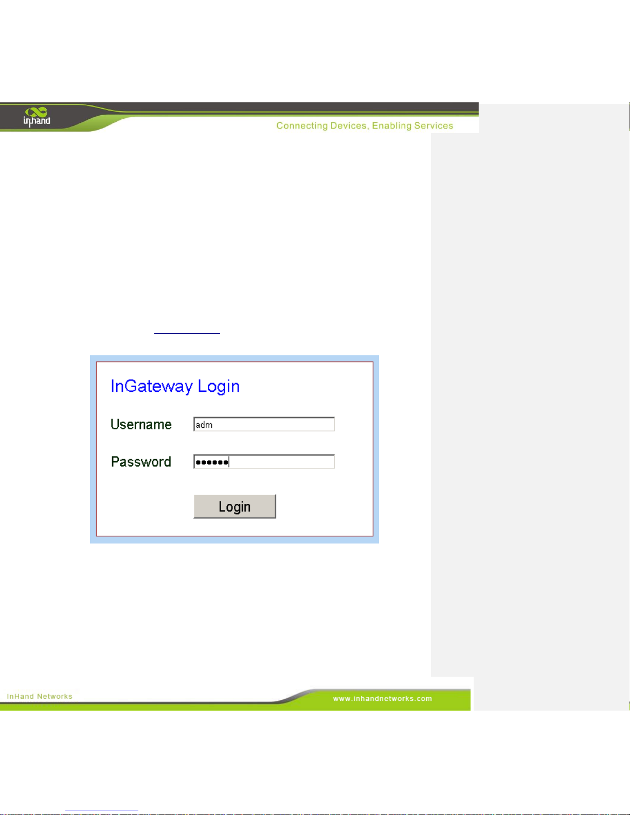
Run the Web browser, enter “http://192.168.2.1” in the address bar, and press Enter to skip to the Web
login page, as shown below. Enter the “User Name” (default: adm) and “Password” (default: 123456).
Click button <Login> or directly press Enter to enter the Web configuration page, as shown below.
Page 19
19 / 92
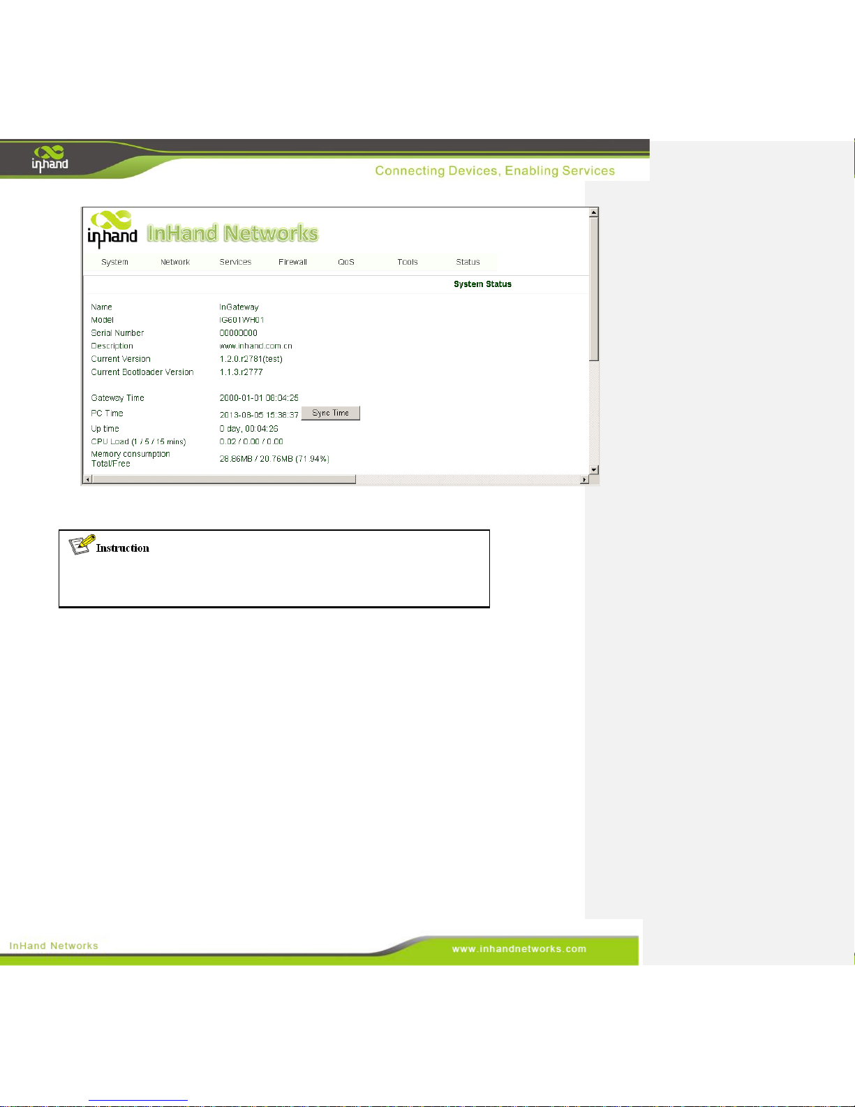
Click <Sync Time> to synchronize the gateway's clock with the system time of the host.
For security, it is highly recommended that you modify the default password after
your first login. Store the password information in a secure location.
3.2 System
The system configuration process involves nine steps:
• Basic Setup
• Time
• Serial Port
• Admin Access
• System Log
• Configuration Management
• Update
• Reboot
• Logout
Page 20
20 / 92
3.2.1 Basic Setup
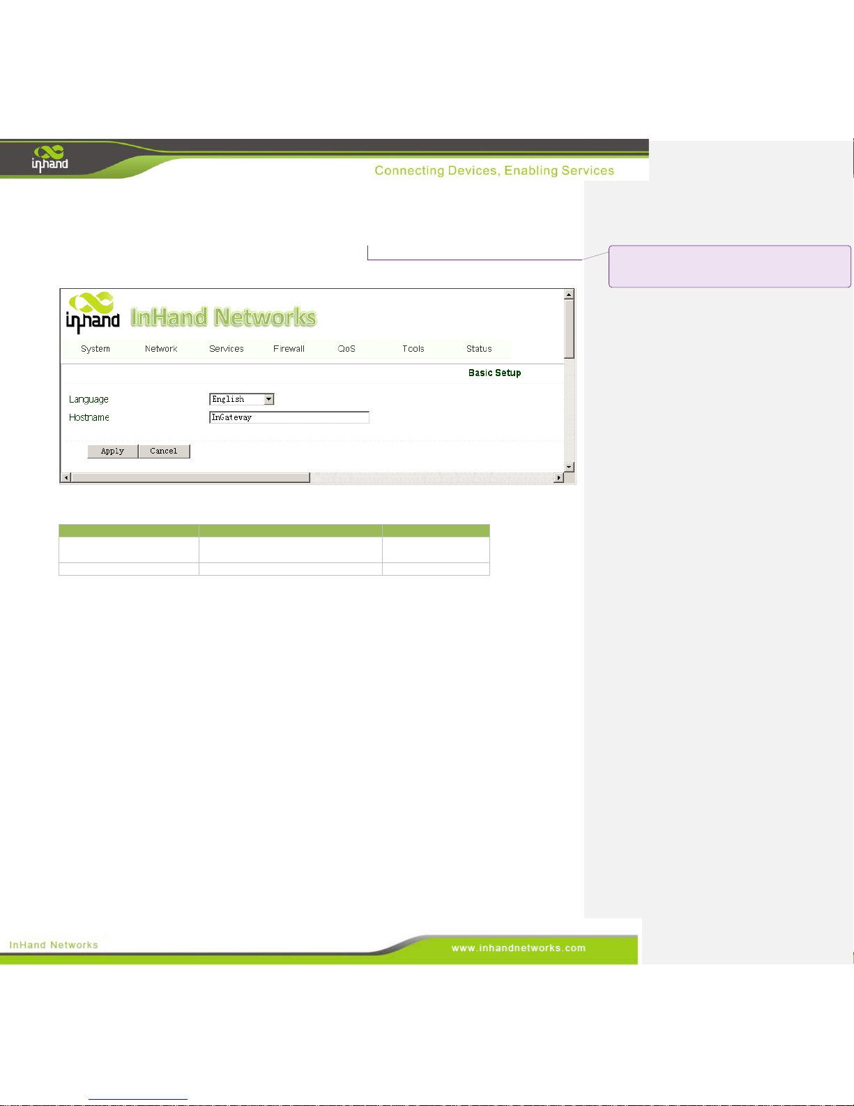
From the navigation panel, select System >> Basic Setup, then enter the “Basic Setup” page, as
shown below.
Page description is shown below:
Parameters
Description
Default
Language
Select the language of configuration
page
English
Hostname
Set the name of InGateway
Gateway
3.2.2 Time
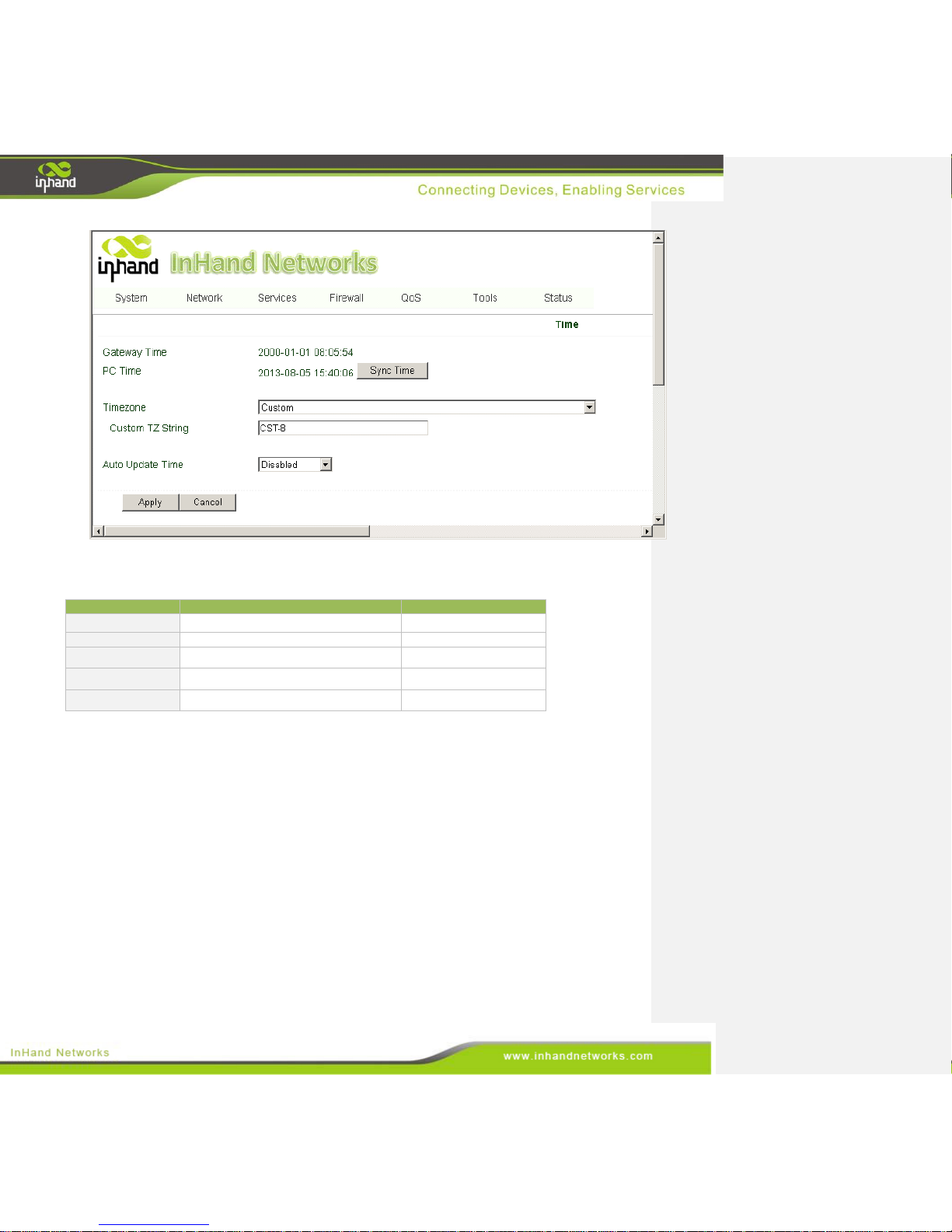
In order to ensure the coordination of the gateway and other devices, users need to set the system time
and time zone correctly. From the navigation panel, select System >> Time then enter the “Time”
webpage, as shown below. Click <Sync Time> to synchronize the time of the gateway with the system
time of the host.
批注 [Unknown A3]: This is inconsistent with the
previous part of the document, but it actually is much
cleaner looking.
Page 21
21 / 92
The terms are explained below:
Parameters
Description
Default
Gateway Time
Display the system time of Gateway
2000-01-01 08:16:47
PC Time
The current time of supervisory PC
N/A
Timezone
Set time zone
Custom
Custom TZ String
Set the time zone of the Gateway
CST-8
Auto update Time
Time Update Interval
Disabled
3.2.3 Serial Port
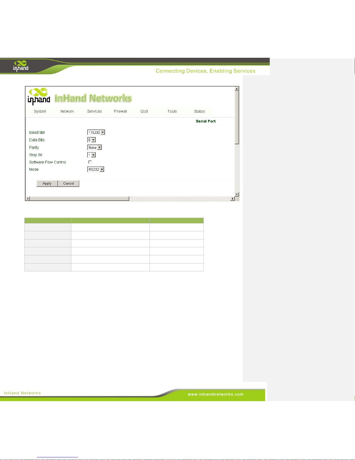
On the serial port settings config page, users need set the serial configuration of the gateway with the
same parameters as the connected device. If users are using software similar to PuTTY, users should set
their serial configs the same as the settings below.
From the navigation panel, select System >> Serial Port, then enter “Serial Port” page, as shown
below.
Page 22
22 / 92
Page description is shown below:
Parameters
Description
Default
Baud Rate
Serial baud rate
115200
Data Bit
Serial data bits
8
Parity
Set parity bit of serial data
None
Stop Bit
Set stop bit of serial data
1
Software Flow Control
Enable Software Flow Control
Disable
Mode
Select serial type
RS232
3.2.4 Admin Access
HTTP
HTTP (Hypertext Transfer Protocol) is used for transferring web pages on Internet. After enabling
HTTP service on device, users can log on via HTTP and access the device using a web browser.
HTTPS
HTTPS (Secure Hypertext Transfer Protocol) supports SSL (Security Socket Layer) and encrypts data
transfers. This prevents man-in-the-middle attacks when data passes either through the local network or
across the internet.
Page 23

23 / 92
TELNET
Telnet protocol provides telnet and virtual terminal functions through a network. The device supports
both a client mode and a server mode. In client mode, the telnet client sends request to the telnet server,
creating a session. While in server mode, the device supports Telnet connections for incoming clients,
allowing for remote access.
Console
The console port, also called the access or serial port, refers for initial configuration and subsequent
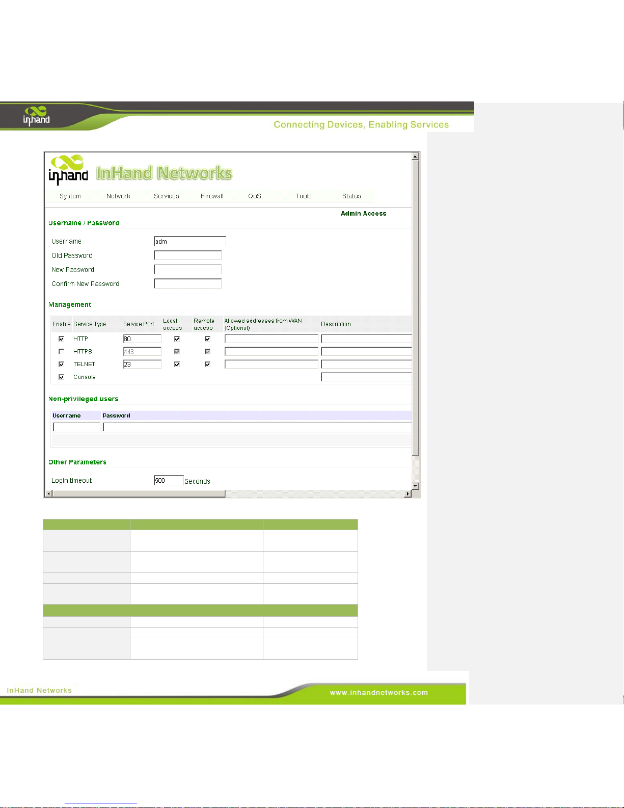
management of a device. It has the same terminal as the telnet client. From the navigation panel, select
System >> Admin Access, then enter “Admin Access” page, as shown below.
Page 24
24 / 92
Page description is shown below:
Parameters
Description
Default
Username
Username for configuration web
login .
adm
Old Password
To change the password, users
must input the old one.
N/A
New Password
Input new password.
N/A
Confirm New
Password
Input the new password again.
N/A
Management:HTTP/HTTPS/TELNET/Console
Enable
Select to enable HTTP.
Enabled
Service Port
Select management port.
80/443/23/N/A
Local Access
Enable—allow management of
the IG601 over the local network,
Enabled
Page 25
25 / 92
or LAN.
Disable—forbid management of
the IG601 over LAN.
Remote Access
Enable—allow management of
the IG601 over the WAN, or
internet.
Disable—forbid management on
a WAN connection.
Enabled
Allowed Access
from WAN
(Optional)
Set the range of IP address that is
allowed access over a WAN
connection. For example
192.168.2.1/30 or 192.168.2.1 -
192.168.2.10.
(HTTP/HTTPS/TELNET)
N/A
Description
Describe the parameters of
management (non-influence to
IG601)
N/A
Parameters
Description
Default
Non-priviledged Users(Console login)
Username
Technician defines a new
username.
N/A
Password
User define the password
N/A
Other Parameters
Log Timeout
Log Timeout
Log Timeout
In “Username/Password” section users can modify username and password.
However, these accounts will be non-privileged, meaning the new users cannot
create new username. A non-privileged account may only do web logins.
In “Non-privileged Users” section, we can create multiple usernames.
Technicians can utilize multiple usernames while logging on a IG601 via serial
port or Telnet.
3.2.5 System Log
A remote log server can be set through “System Log Settings,” and all system logs will be uploaded to
the remote log server through the gateway. This makes remote log software, such as Kiwi Syslog
Daemon, is a necessity on the host.
Page 26
26 / 92
Kiwi Syslog Daemon is free log server software for Windows, which can receive, record and display
logs from host (such as gateway, exchange board and Unix host). After downloading and installing
Kiwi Syslog Daemon, it mus be configured through the menus “File >> Setup >> Input >> UDP.”
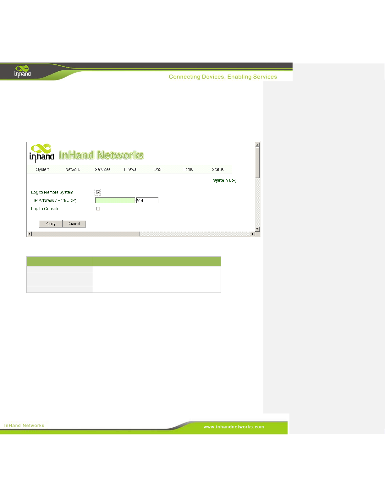
From the navigation panel, select System >> System Log, then enter “System Log” page, as shown
below.
Page description is shown below:
Parameters
Description
Default
Log to Remote System
Enable remote log server
Disable
IP address/Port (UDP)
Set the IP and Port of remote log server
N/A/Port:
514
Log to Console
Print the log to console.
Disable
3.2.6 Config Management
Users may import an old configuration or backup the current configuration.
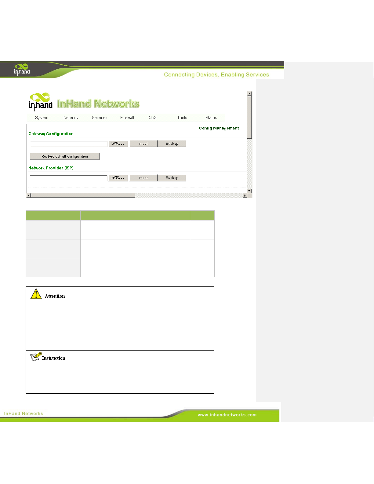
From the navigation panel, select System >> Config Management, then enter the “Config
Management” page, as shown below.
Page 27
27 / 92
Page description is shown below:
Parameters
Description
Default
Gateway
Configuration
Import/Backup configuration
N/A
Restore default
configuration
Click to reset IG601. To complete the reset,
users need to reboot the IG601.
N/A
Network Provider
(ISP)
The technician must configure the local APN,
username, password, and other configs the
same as their ISP.
N/A
Be sure to check imported configs for incorrect formats and completeness. When
importing, the system will filter the improperly formatted commands and save the
correct configuration. The good configs will later be serially executed in order after
system reboot. The system will not get into expected state in the case that the
imported configuration is not arranged according to an effective order.
In order not to affect the operation of the current system, when performing an
import configuration and restore default configuration, users need to restart the
gateway to make the new configuration to take effect
Page 28
28 / 92
3.2.7 System Upgrade
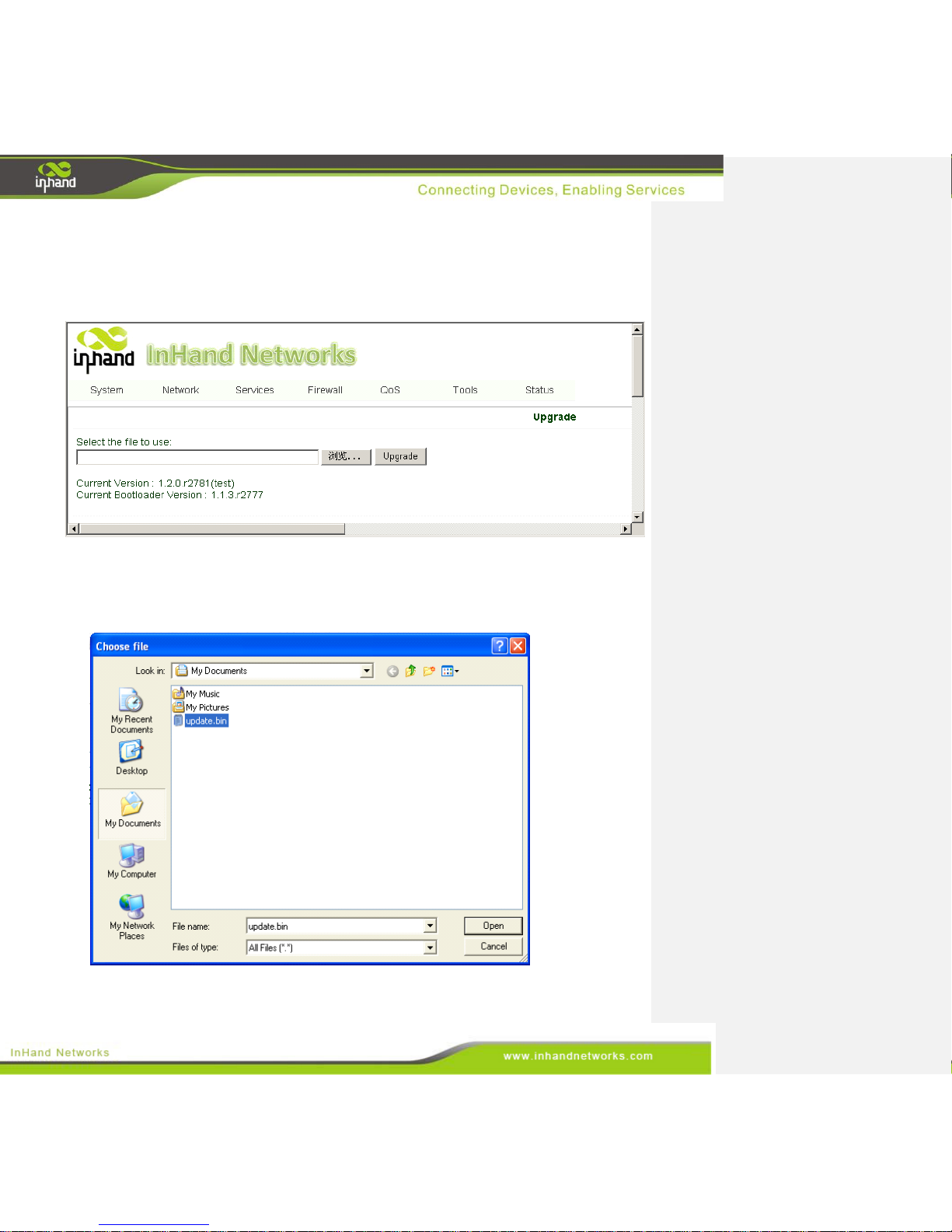
From the navigation panel, select System >> Upgrade, then enter the “Upgrade” page, as shown
below.
To upgrade the system, click the System, tab then <System upgrade> to enter upgrade page, then
follow the steps below:
Step one: Click <Browse> choose the upgrade file, and then click <Open>, as shown below:
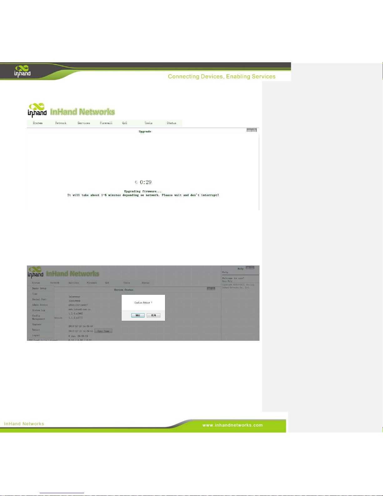
Step Two: Click <Update> and then click <OK> to begin updating. Make sure your screen matches the
Page 29
29 / 92
picture below.
Step Three: Upgrade firmware succeed, and click <Reboot> to restart the IG601.
3.2.8 Reboot
If users need to reboot system, please click the System tab, then <Reboot> and click <OK> to restart
the system.
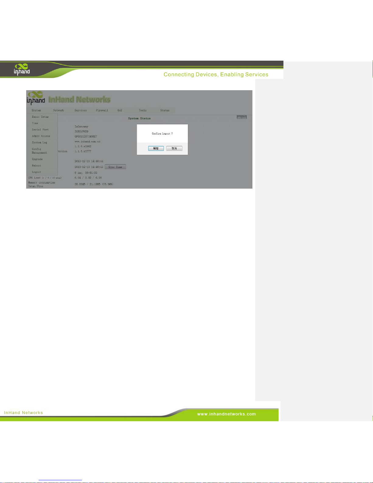
3.2.9 Logout
If users want to logout, click System >> Logout, and then click <OK>.
Page 30
30 / 92
3.3 Network
This section covers network settings include Dialup/Cellular, LAN, DNS, DDNS, and Static Routes.
3.3.1 Dialup/Cellular Connection
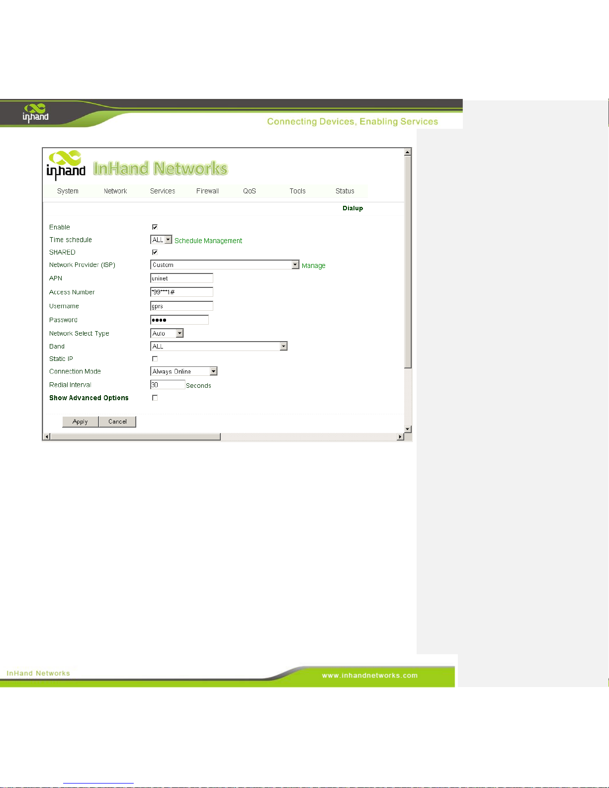
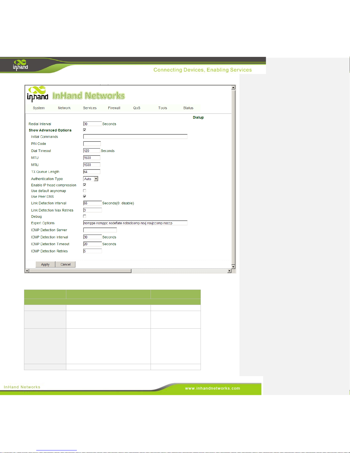
With following configuration, IG601 can access the internet through the wireless cellular network.
From the navigation panel, select Network >> Dialup, then enter the “Dialup” tab, as shown below.
Page 31
31 / 92
Page 32
32 / 92
Terminology is listed below:
Parameters
Description
Default
Basic Config
Enable
Enable PPP dialup.
Enable
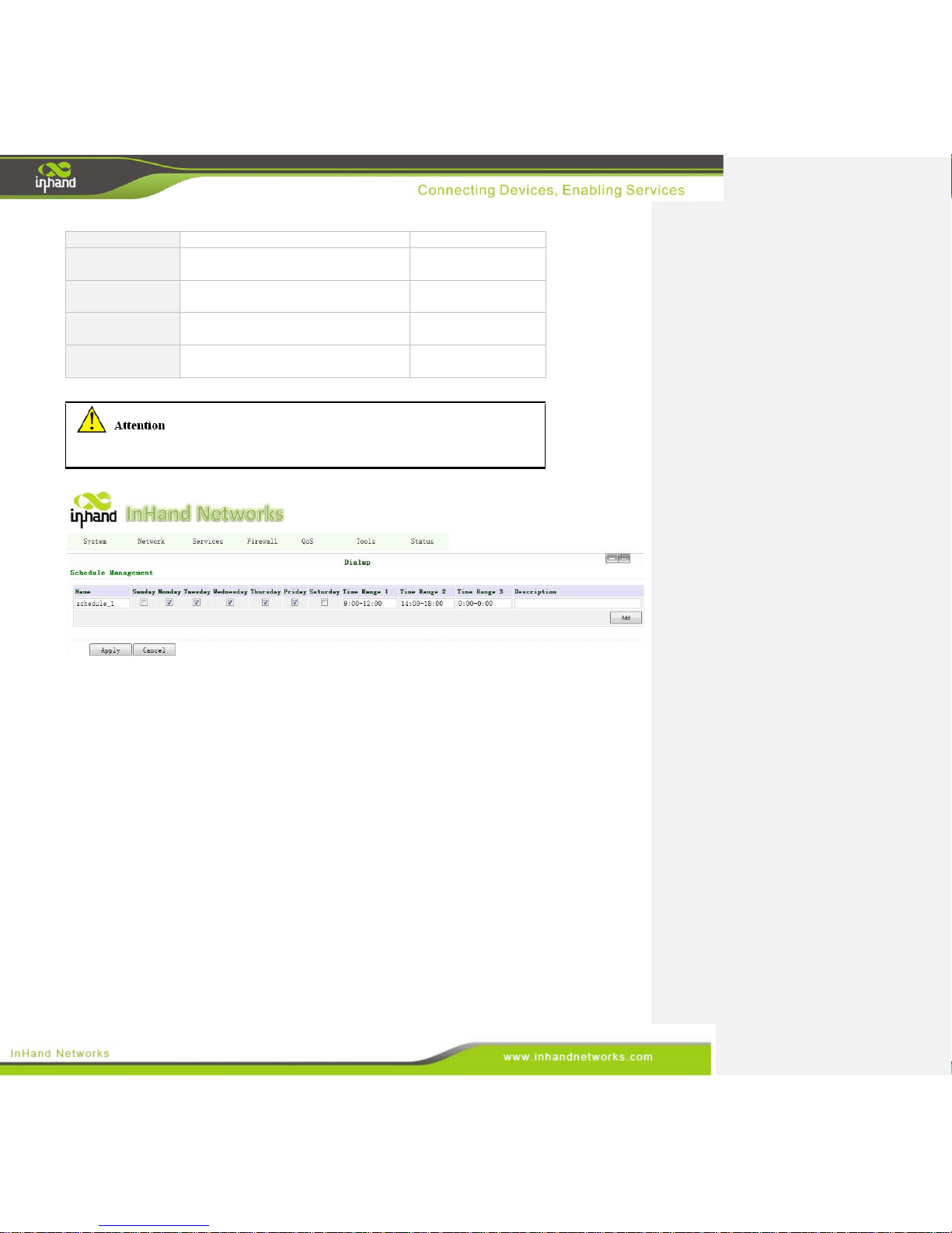
Time Schedule
Select timetable for online and offline.
We need defined timetable through
“Schedule Management” in advance.
ALL
SHARED
Enabled—enable “NAT,” or network
address translation. Local addresses
can be translated to global WAN
address on a one-to-many basis.
Disable—disable “NAT.”
Enable
ISP
Select local ISP, if not listed here,
Customer
Page 33

33 / 92
please select “Customer.”
APN
APN provided by your Local ISP
Uninet
Access Number
Dialup phone number provided by
your Local ISP.
*99#/*99***1# /
#777
Username
Some APNs need a username and
password to complete the PPP
connection, but not every APN needs a
username.
GPRS
Password
Some APNs need a username and
password to do the PPP connection,
but not every APN needs a password.
GPRS
Network Select
Type
Choose mobile network type. The
available options are “auto”, “2G
only” and “3G only.”
Auto/ 2G only / 3G
only
Static IP
Enable a static IP if your SIM card can
get a static IP address.
Disable
Connection Mode
It may be set to either “Always
Online,” “Connect On Demand,” or
“Manual.”
Always Online
Redial Interval
When a dialup fails, InGateway will
redial after an interval.
30 seconds
Advanced Options
Initial Commands
Used for advanced parameters.
N/A
PIN code
Set the use of the SIM card PIN code.
N/A
Dial Timeout
Set dialup timeout. The IG601 will
reboot after timeout.
120 seconds
MTU
Set max transmit unit, or max frame
size. Set this number to 1500 for
normal frames and larger for little big
frames.
1500
MRU
Set max receive units.
1500
TX Queue Length
Set length of transmit queue.
64
Authentication
Type
Select either Auto, PAP or CHAP. This
is nessecary for some ISP connections.
Auto
Enable IP header
compression
Enable IP header compression
Enable
Use default
asyncmap
Enable default asyncmap, and PPP
advanced option.
Disabled
Use Peer DNS
Use the assigned DNS server.
Enable
Link Detection
Interval
Set the Link Detection Interval.
55 seconds
Link Detection
Max Retries
Set the max retries if a link detection
failed.
3
Debug
Enable debug mode.
Disable
Expert Option
Provide extra PPP parameters,
normally user don't need to set these.
Options include: nomppe nomppc
nodeflate nobsdcomp novj novjccomp
N/A
Page 34
34 / 92
noccp.
ICMP Detection
Server
Set the ICMP Detection Server. Blank
represents none.
Blank
ICMP Detection
Interval
Set the ICMP Detection Interval.
30 seconds
ICMP Detection
Timeout
Set ICMP Detection Timeout (IR6X1
will reboot if ICMP time out)
20 seconds
ICMP Detection
Max Retries
Set the max number of retries if ICMP
failed
5
Configure the device's schedule to set any downtime.
To set the devices schedule, go into the “Dialup” window, enter the “Schedule Management” page.
3.3.2 LAN
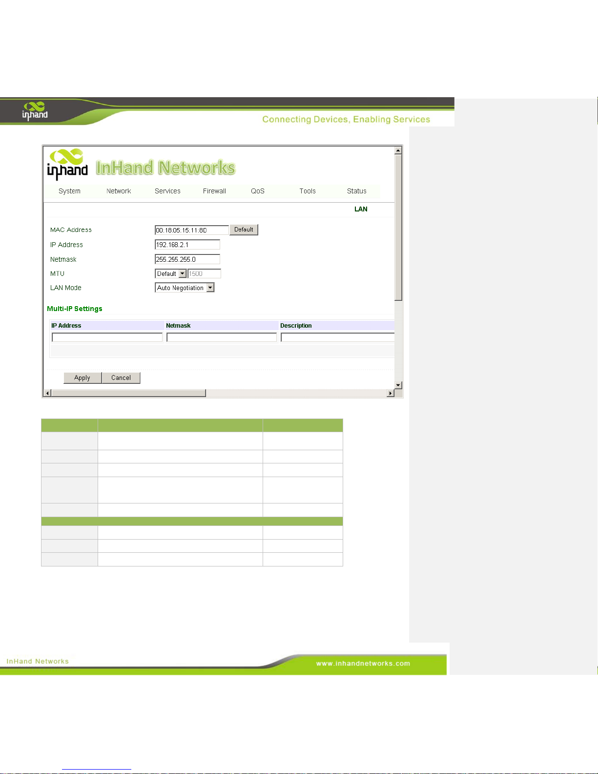
To create a static LAN connection, go into the navigation panel, select Network >> LAN, then enter
the “LAN” page, as shown below.
Page 35
35 / 92
The settings are explained below:
Parameters
Description
Default
MAC Address
The host MAC address in LAN, which is provided
by the manufacturers.
00:18:05:15:11:8D
IP Address
Set the IP Address in LAN
192.168.2.1
Net mask
Set the subnet mask of a local network.
255.255.255.0
MTU
Set MTU length options to either Default or
Manual. 1500 is the normal frame size for Ethernet
v2.
1500
LAN Mode
100M Full/duplex,100M Half/duplex.
Auto Negotiation
Multi-IP Settings
IP Address
Set additional IP Address of LAN
N/A
Netmask
Set netmask of LAN
N/A
Description
Description about this IP address
N/A
3.3.3 DNS
At the core of the internet lies DNS or the domain-name system. It employs a distributed database
(DDB) to map domain names and IP addresses across the web. DNS makes it convenient to access the
Page 36
36 / 92
internet, so that instead of memorizing IP numbers, people can use words to make domain-names.
The device supports the following two functions through the domain name configuration service:
DNS Server: the device can function as a local DNS Server.
DNS relay: as a DNS agent, the device can transfer DNS request and response messages between
the DNS client and server, while and executing domain name analysis in place of the DNS Client.
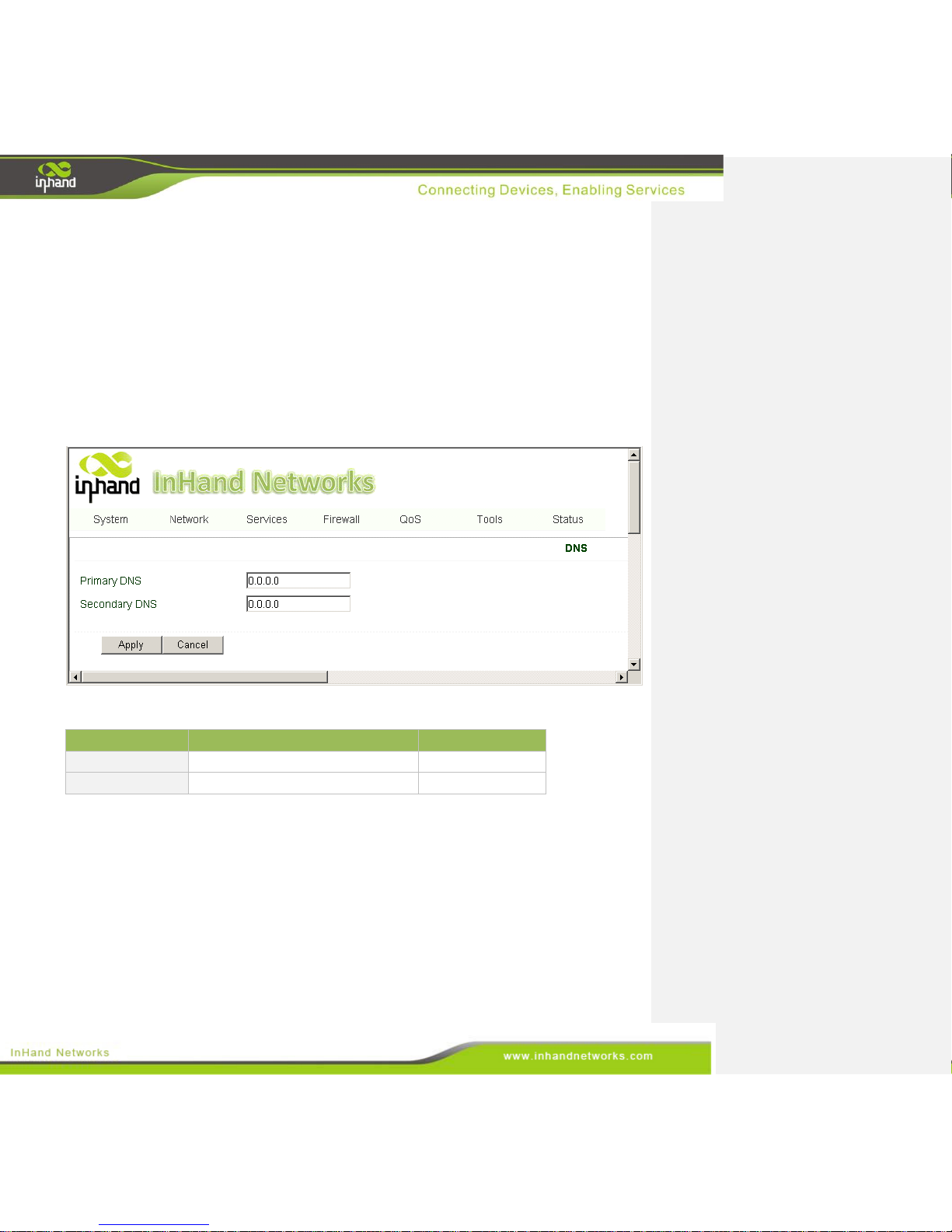
To begin setting up the DNS client, find the navigation panel, select Network>>DNS to enter into the
“DNS” window and manually set the DNS information. If the DNS information is empty, it can be
found via dialup. Generally, users will only need to set the dialup DNS settings if they have static
routes on the gateway.
Page description is shown below:
Parameters
Description
Default
Primary DNS
Set Primary DNS
N/A
Secondary DNS
Set Secondary DNS
N/A
3.3.4 DDNS
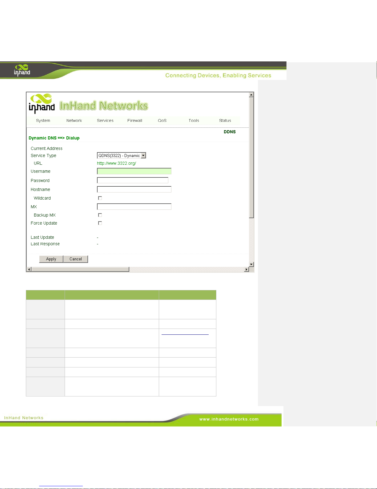
DDNS (Dynamic Domain Name Server) automatically adds DNS entries to a server in real time.
DDNS automatically logs IP addresses and host-names to its database when hosts connect to the
network. When hostnames have been recorded, they may be used in the place of IP addresses. DDNS
will be particularly useful in an IPv6 environment.
To set up DDNS, go into the navigation panel, select Network >> DDNS, then enter “DDNS” page, as
shown below.
Page 37
37 / 92
Page description is shown below:
Parameters
Description
Default
Current
Address
Show the current IP address
Blank
Service Type
Select DDNS Provider
Disabled
URL
Automatically generate, users do not
need to set
http://www.3322.org/
Username
Registered username for DDNS
N/A
Password
Registered password for DDNS
N/A
Hostname
Registered hostname for DDNS
N/A
Wildcard
Set whether the server supports
wildcards
Disabled
Page 38
38 / 92
MX
Whether to update the mailbox record
N/A
Backup MX
Whether to update the mailbox record
Disabled
Force Update
Force update records after modifying
the settings
Disabled
3.3.5 Static Routes
Static routes are created manually and have many different uses. After the static route is set, packets
will be transferred to appointed routes. Engineers can create simpler networks by using static routes in
place of RIP or OSPF, and ensure greater network reliability. The proper setting and use of static
routing can also improve the performance of a network and guarantee bandwidth for important network
applications.
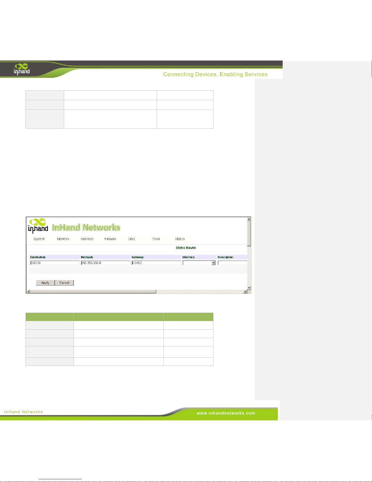
From the navigation panel, select Network >> Static Route, then enter “Static Route” page, as shown
below.
Page description is shown below:
Parameters
Description
Default
Destination
Set IP address of the destination
0.0.0.0
Net Mask
Set subnet mask of the destination
255.255.255.0
Gateway
Set the gateway of the destination
N/A
Interface
Users can select which interface accesses
the destination
N/A
Description
Describe a static route
N/A
Page 39
39 / 92
3.4 Service
In the service section, this manual covers nine configurations, including DHCP service, DNS relay,
VRRP, Device Manager, DTU, Modbus to SMS, SMS alarm rules, and Mbsms variable template.
3.4.1 DHCP Service
DHCP (Dynamic Host Configuration Protocol) is a network protocol for LAN utilizing UDP and TCP.
DHCP automatically distributes IP addresses for either a local network or network service provider, and
can aid network administrators in managing all the computers on a network. A DHCP server refers to a
computer managing DHCP standard in a network. It distributes IP addresses once the work station logs
on and ensures that no duplicate IP addresses are assigned. DHCP Server dramatically simplifies
network management tasks, and is a necessity in today's network.
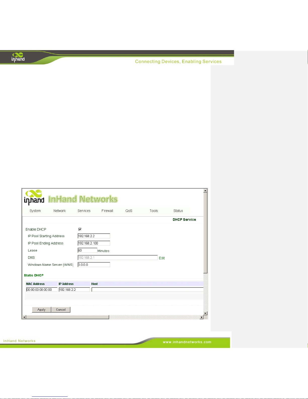
To enable the DHCP server, find the navigation panel, select Services >> DHCP Service, then enter
“DHCP Service” page, as shown below.
Page 40
40 / 92
The page is described below:
Parameters
Description
Default
Enable DHCP
Check to enable DHCP.
Enable
IP Pool
Starting
Address
Set the starting IP address of DHCP
pool.
192.168.2.2
IP Pool Ending
Address
Set the ending IP address of DHCP
pool.
192.168.2.100
Lease
Set the valid time lease of IP address
obtained by DHCP
60 minutes
DNS
Set DNS Server
192.168.2.1
Windows
Name Server
(WINS)
Set the WINS binding.
0.0.0.0
Static DHCP
MAC Address
Set the MAC address of a designated
IP address.
00:00:00:00:00:
00
IP address
Set the static IP address of the host.
192.168.2.2
Host
Set the hostname.
N/A
3.4.2 DNS Relay
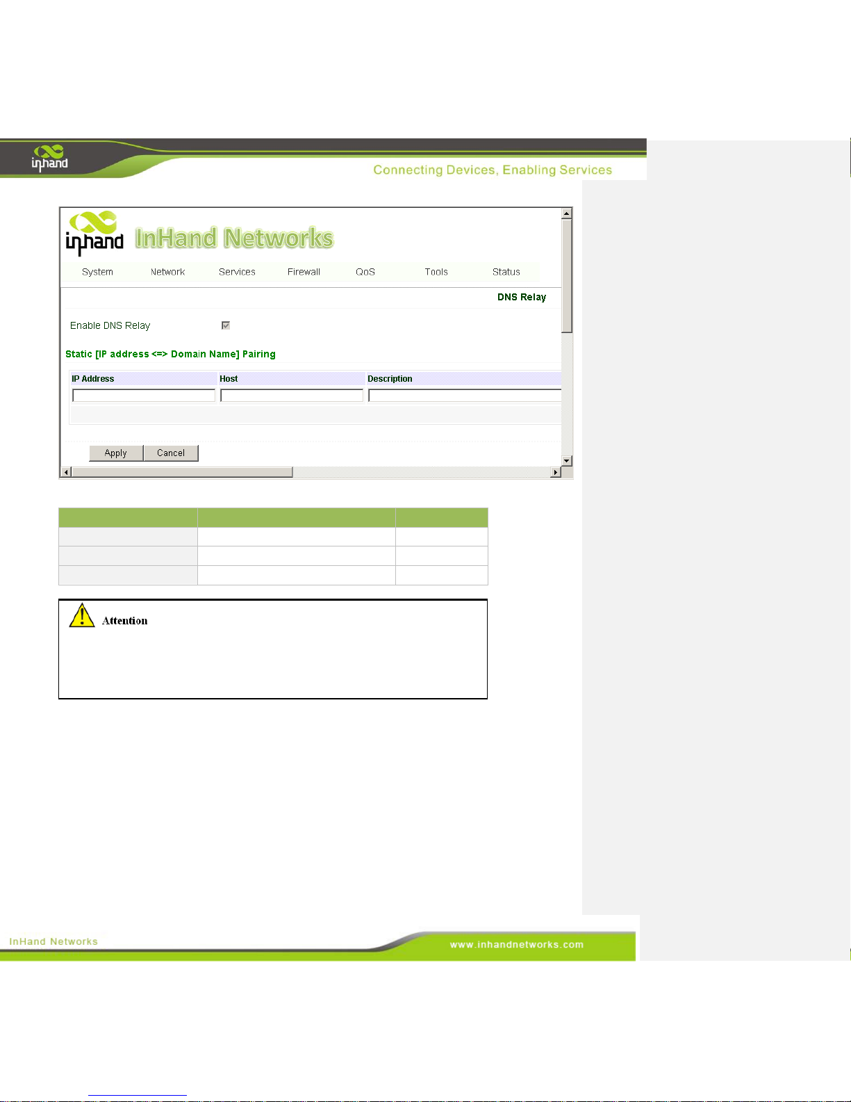
DNS forwarding: DNS forwarding is open by default. You can set the specified [Domain Name <=> IP
Address] to let IP address match with the domain name, thus allowing access to the appropriate IP
through accessing to the domain name.
From navigation panel, select Network >>DNS, then enter “DNS Relay” page, as shown below.
Page 41
41 / 92
The page description is shown below:
Parameters
Description
Default
IP Address
Map an IP to a hostname.
N/A
Host
Set the name of DNS entries.
N/A
Description
Describe DNS entry.
N/A
When enabling DHCP, the DHCP relay is also enabled automatically. Relay
cannot be disabled without disabling DHCP.
While using dynamic DNS, the DNS relay service should be turned on.
A maximum of twenty IP to domain-name pairs may be configured.
3.4.3 VRRP: Virtual Router Redundancy Protocol
VRRP is a protocol for allowing automatic failover and redundancy in routers. It creates a “virtual
router,” meaning multiple physical routers can be assigned to one gateway or one host. The main
gateway controls the IP of the virtual gateway and routes packets to virtual IP addresses. If the main
gateway drops, a dynamic failover process elects a new gateway. The IP address of the virtual gateway
can be set as the default gateway for hosts, because it is the first hop. The benefit of using VRRP is
serviceability. The network administrator can avoid the configuration of dynamic routing or routing
discovery protocol on each host. VRRP packet is sent encapsulated in IP packet.
Page 42
42 / 92
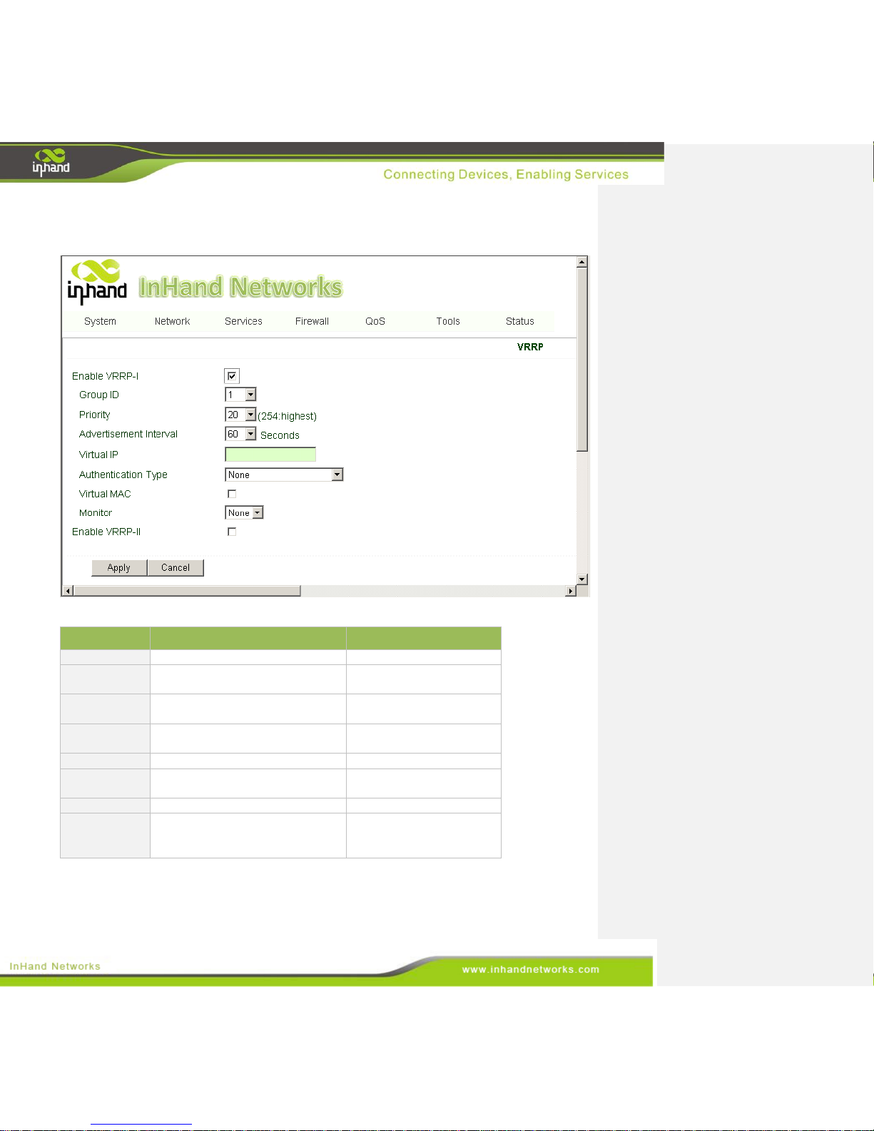
To enable VRRP, go to the navigation panel, select Services >> VRRP, then enter “VRRP” page, as
shown below.
The page description is shown below:
Parameters
Description
Default
Enable
Check to enable VRRP.
Disable
Group ID
Select a group id of gateway (range
1-255).
1
Priority
Select a priority for the gateway
(range 1 - 254).
20 (bigger number stands
for higher priority)
Advertisement
Interval
Set an advertisement interval.
60 sec
Virtual IP
Set a Virtual IP address.
N/A
Authentication
Type
Choose between "None" or
Password type.
None
Virtual MAC
Select to enable.
Disable
Monitor
Select WAN to start monitoring
WAN interface traffic; select None
do not monitor.
None
3.4.4 Device Manager
The device manager, or DM, is the InHand intelligent cloud platform for network management service.
Page 43
43 / 92
You can remotely manage your IG601, find the current status and so on.
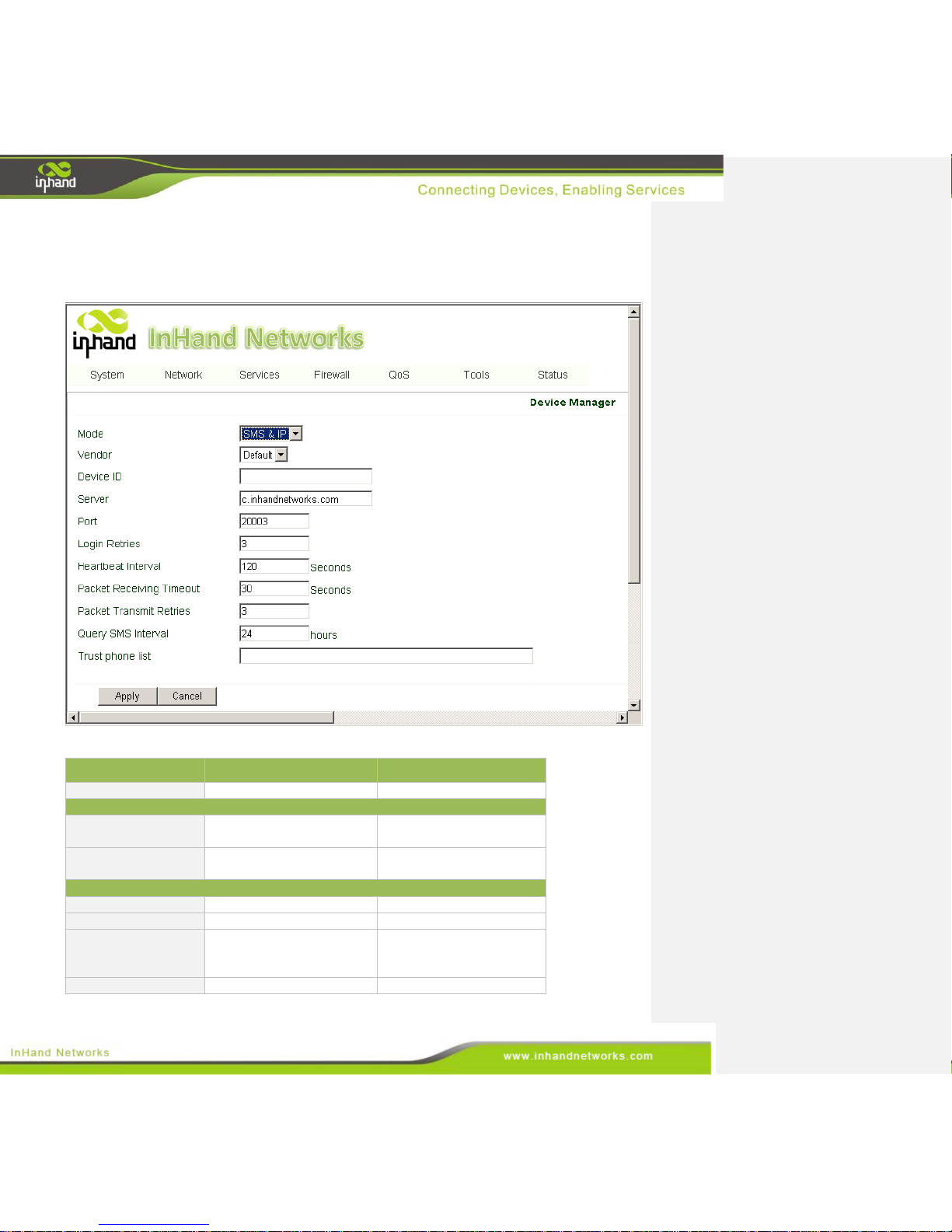
To configure the device manager, go to the navigation panel, select Services >> Device Manager, then
enter “Device Manager” page, as shown below.
Terms are described below:
Parameters
Description
Default
Mode
SMS+IP is recommended.
Disable
Only SMS
Query SMS Interval
Set how frequently to check
SMS.
24 hours
Trust Phone List
Add trusted cell phone list,
also known as a white list.
N/A
SMS+IP
Vendor
Set a vendor name.
Default
Device ID
Set a device ID.
N/A
Server
Set a device manager server
IP:
g.inhandnetworks.com
c.inhandnetworks.com
Port
Set a port for device
20003
Page 44
44 / 92
manager.
Login Retries
Set login retries
3
Heartbeat Interval
Set interval of heartbeats.
120 seconds
Packet Receiving
Timeout
Set the timeout for dropped
packets.
30 seconds
Packet Transmit
Retries
Set packet transmit retries.
3
Query SMS Interval
Set how long to check SMS.
24 hours
Trust phone list
Set a trusted cell phone list.
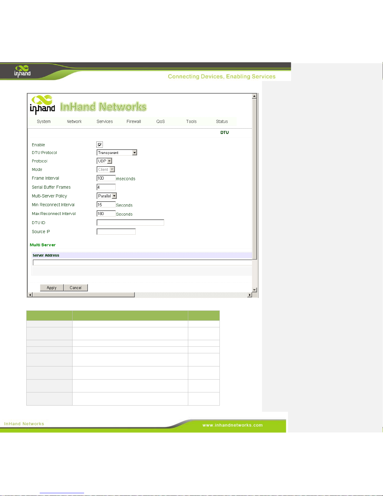
3.4.5 DTU
If you connect a serial device to IG601, you need enable the DTU converter. IG601 can support a
multi-protocol uplink to allow conversion of serial data and IP data. Users must select the correct serial
mode on the window “Serial Port” from the navigation tab “System.”
To enable the DTU, go into top navigation panel, select Services >> DTU, then enter “DTU” page, as
shown below.
Page 45
45 / 92
The page is described below:
Parameters
Description
Default
Enable
Check to enable the DTU.
Disable
DTU Protocol
Set the DTU protocol. Please see more in related
Quick Guide.
Transparent
Protocol
TCP and UDP are both options.
UDP
Mode
Set the DTU as a client or server.
Client
Frame Interval
Set the frame interval.
100
mseconds
Serial Buffer
Frames
Set the number of serial buffer frames.
4
Multi-Server
Policy
Choose either parallel or poll options.
Parallel
Min Reconnect
interval
Set the minimum reconnect interval.
15s
Page 46
46 / 92
Max Reconnect
interval
Set the maximum reconnect interval.
180s
DTU ID
Set the ID of the DTU. It's only available when
using DC protocol.
N/A
Source IP
Set the Source IP.
N/A
3.4.6 Modbus to SMS
InGateway inquires the variables status of the PLC every ten seconds and saves them into RAM.
These variables will be the SMS response sent after a query. After receiving a control SMS, InGateway
sends the control command to the PLC and waits for a response. The response is sent from the PLC and
then InGateway sends the response to the user.
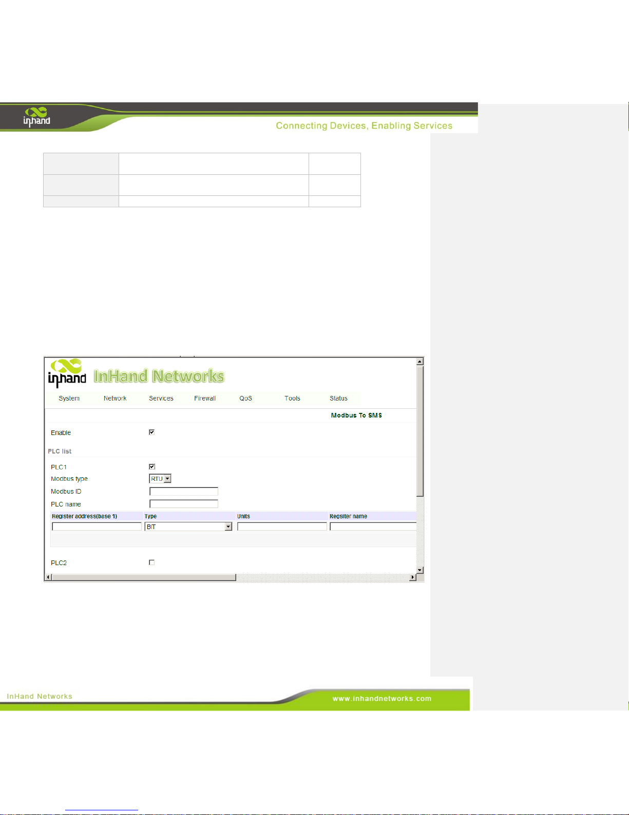
To enable SMS, find the navigation panel, select Services >> Modbus to SMS to enter into the
“Modbus to SMS” page. After you add your PLC here, the daemon of IG601 periodically queries the
PLC variables and cache to memory.
Follow the five steps below to configure the PLC parameters:
Step 1: Click ‘Enable’ in ‘Service>>Modbus to SMS’
Step 2: Unfold configuration item of “PLC List” and click the PLC to be used, and configure one by
one. 8 PLCs could be added on this page.
Step 3: Configure the specific parameters of PLC, each PLC can be added to 32 variables.
Page 47
47 / 92
1) Set the Modbus type: RTU and TCP are available.
2) Under RTU type, configure the slave address of each PLC, namely the ‘Modbus ID.’ It may be
assigned a value from 1 to 247. Under TCP mode, configure the IP address and port number of
PLC.
3) Configure name of the PLC, using a maximal length of 16 bytes. Specific PLC name will be
used in SMS.
4) PLC Authen: set authentication password to ensure the PLC is tamper-evident. As the password
is saved to register 40100-40103, the register 40100-40103 cannot be used when configuring
register.
5) New Variables:
First column is register address (from 1). 0xxxxx is for discrete inputs. 1xxxxx is for a
coil. 3xxxxx is for the incoming register, and 4xxxxx indicates a holding register.
Second column is the variable type, supporting BIT, WORD, DWORD, FLOAT, INT16,
INT32 and INT64.
Third column is the units of variable with maximum length of 8 bytes. This value will
appear in SMS, and you can leave this field empty. The unit of BIT variables should be
configured according to HH/LL format, HH represents the corresponding unit of “1,” LL
represents the corresponding unit of “0.” The units of other types of variables will appear
directly in SMS.
Fourth column is register name with a maximum length of eight bytes. Users can define
names for each variable and this field must be filled. The variable address will be replaced
by variable name in SMS.
PLC ID in IG601 cannot be repeated, neither can PLC names.
Variable names cannot be repeated in one PLC variable list.
Each PLC should be defined with ID, name and at least one variable.
Click “Add” to add new variables.
Step 4: Repeat step 3 and add more PLCs.
Step 5: Click <Apply> button, save and apply the new configuration.
Page 48
48 / 92
3.4.7 SMS Alarm Rules
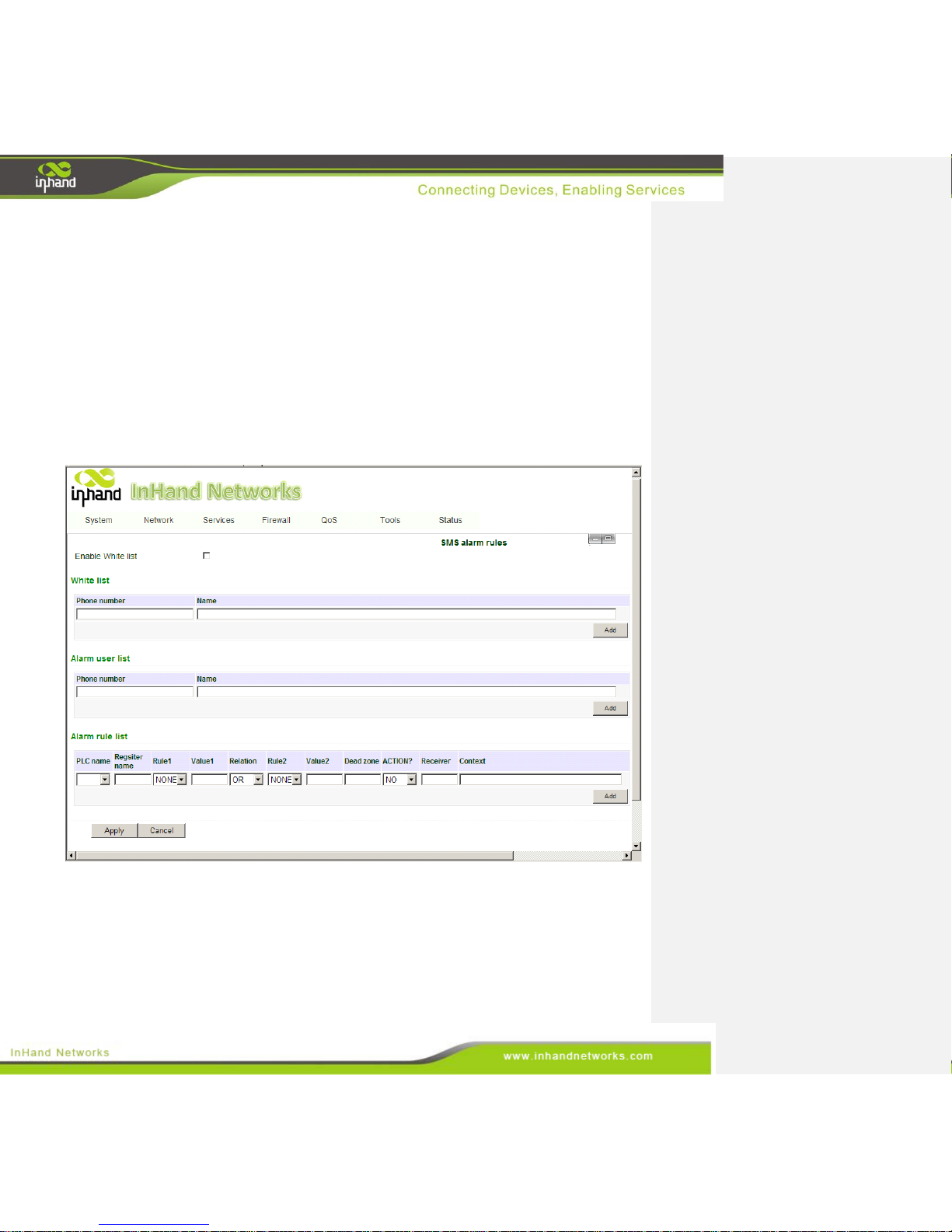
IG601 supports the configuration of up to one-hundred alarm rules, that when triggered send an alarm
message to user’s mobile phone. User can set the alarm rules, and adjust the SMS receiver in the alarm
menu. The IG601 will collect different variables depending on the alarm rules set by the user. When a
variable matches the rules, IG601 will send an SMS alarm to all users on the “alarm user list”. IG601
can also send user-defined SMS to designated users.
There is timestamp and WAN IP settings, users can define SMS contents.
From the navigation panel, select Services >> SMS Alarm Rules, then enter the “SMS Alarm Rules”
window, as shown below. After setting SMS, click the <Apply> to save and apply the configuration.
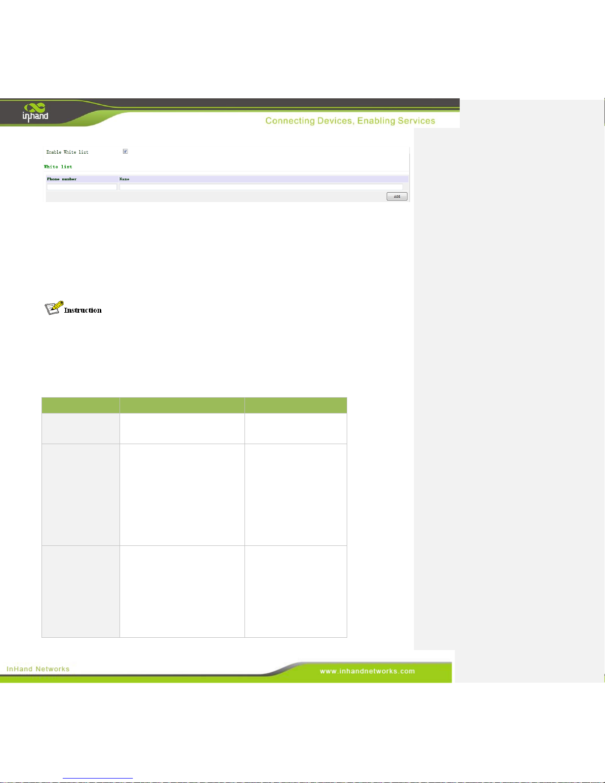
3.4.7.1 Enable White list
The IG601 is capable of receiving a control and inquiry SMS from any user. In order to improve
security, users can enable the white list function. After the white list is set, the IG601 only processes
SMS from users on the white list, meaning any other SMS will be dropped.
Page 49
49 / 92
Up to 10 users may be whitelisted.
The first column is a telephone number, with a length ranging from 1 to 16 bytes, and is mandatory.
The second column is the user name, with a length ranging from 0 to 16 bytes, and is optional.
After enabling the “Modbus to SMS” function, IG601 can identify two types of SMS commands sent
by the users on the white list. The IG601 performs an action corresponding to different commands and
then sends a response to the SMS user.
Users can send SMS to IG601 via mobile phone or SMS modem. Two types of SMS formats and
response message are as follows:
The SMS to inquire state
Users can send the following SMS command to inquire the IG601 operating status and the register
values of the PLC.
Request
Response Message
Description
GET
plc1 connected
plc2 disconnected
Inquire about the name
and status of all PLCs
connected to the IG601.
GET plc1_name,
plc2_name…
plc1 OUTPUT1=on
OUTPUT2=off
plc2 OUTPUT3=on
OUTPUT4=on
Inquire about the PLC
variables with names of
plc1_name, plc2_name.
The plcX_names are
parameter. Users can
query different PLC
variables by modifying
the plcX_name. Different
PLCs are separated by a
comma.
GET plc1_name
register1
register2,
plc2_name
register3
register4,…
Plc1 register1=5 register2=6
plc2 register3=1.8 register4=2.2
This command finds the
value of a variables under
a PLC named
plcX_name. The
plcX_name and registerX
are parameters. Users can
find the name of
corresponding variables
by trying different
Page 50
50 / 92
perameter commands. By
entering multiple
registers, multiple
variables can be found at
the same time. Different
PLCs are separated by
comma.
Request
Response Message
Description
ALARM
Alarm total: 55, #53 date-time
context1, #54 date-time
context2, #55 date-time context3
Find a count of historical
alarm records and return
the latest three historical
alarms.
ALARM 2-3
Alarm total: 55, #2 date-time
context1, #3 date-time context2,
#4 date-time context3
Inquire about historical
records within the
appointed number range.
It can request maximum
of five historical records
each time.
NETSATUS
Signal strength(dBm):xx,
Network status: Registered to
home network
Learn the network status.
MSGSTATUS
Received message: 10, Sent
message: 15, Failed sent
message: 0, Unauthorized
message: 7
Inquire about the SMS
statistics.
WHITELIST
WHITELIST ON|OFF
Inquire about the startup
status of the white list.
The SMS to perform actions
User can send the following SMS command to do the configuration via SMS.
Request
Response Message
Description
SET plc1_name
register1=xxx
register2=xxx,
plc2_name
register3=xxx
register4=xxx…
Succeed:
Set register1 to xxx
set register2 to xxx
set register3 to xxx
set register4 to xxx
For a PLC named
plc1_name, set the register
value to xxx. The plcX_name
and registerX are both
parameters. User can set the
corresponding variables by
configuring these parameters
in the command line. Such
commands can set multiple
variables synchronously.
Different PLCs are separated
by comma.
ALARM CLEAN
ALL
Delete 1-55 alarm
SUCCESS
Delete all the historical alarm
records.
Page 51
51 / 92
ALARM CLEAN xxxx
Delete xx-xx alarm
SUCCESS
Delete the historical records
within the a range.
WHITELIST ON|OFF
WHITELIST ON|OFF
Start or stop using a white
list.
ADD 13812345678
ADD 13812345678 OK
Add users to the alarm list.
DELETE
13812345678
DELETE 13812345678
OK
Delete users on an alarm list.
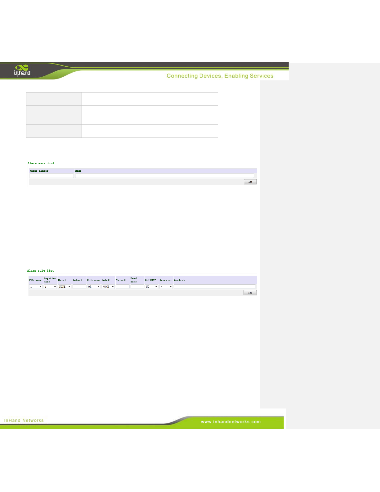
3.4.7.2 Alarm User List
Up to ten alarm recipients can be added to the “alarm user list.”
Mobile phone numbers are filled in the first column, and may range from 1 to 16 bytes long. This
column must be filled; otherwise users cannot be added.
User names are filled in the second column, and may range from 0 to 16 bytes long. This column
may be left empty.
Telephone numbers cannot be repeated.
3.4.7.3 Alarm Rule List
In this section of interface, the technician will create an "alarm rule list.” Each line defines an alarm
rule and a maximum of one-hundred alarm rules can be configured. The technician will match
mathematical expressions and compare values to a variable in each rule. To set an alarm rule follow
these steps:
Select a PLC in the first column. Any PLC previously setup in the “Modbus to SMS” chapter of
this manual will appear in a drop-down menu.
Select a variable name in the second column, and the corresponding variable of the PLC will
appear above it. The technician will compare values to this variable.
Compare the variable to a value by selecting an operator in the third column. The available options
are: NONE, >, >=, <, <=, = and !=.
Define the first value in the fourth column. This value will be compared to the main variable. For
Page 52
52 / 92
example, temperature >= 200 means that when the temperature is greater than or equal to 200, an
alarm will be sent.
Define the relationship between the first expression and the second expression in the fifth column
by selecting OR, AND or XOR.
Select a second operator in the sixth column. The options that can be selected are: NONE, >, >=, <,
<=, = and !=.
Define a second value in the seventh column.
In the eighth column, the user must define a dead zone, which acts as a buffer. After the alarm is
trigger, it will not be sent until the variable exceeds the dead zone value. It is only effective for
numerical, non BIT values. Set the value to zero to eliminate the dead zone.
In the ninth column titled “ACTION?,” users may select “YES” to enable user-defined alarm
message, user need define the alarm message on “Context” in the eleventh column. Otherwise, the
default alarm message will be sent. The maximum length for a short message is 140 bytes.
The mobile phone number of a recipient is input in the tenth column.
A user-defined alarm message may be set in the eleventh column. When triggered, this message
will be sent in the form of an SMS.
The alarm SMS are divided into two types:
If the selection for “ACTION?” in the ninth column is NO, the system will send the automatically
generated defaulted alarm short message. The message will be defined by the variable, for example:
“Alarm plc2 OUPUT=on,” or “Alarm plc AB_VOLT=238V.”
If the selection of “ACTION?” is YES, the system will send a user-defined alarm.
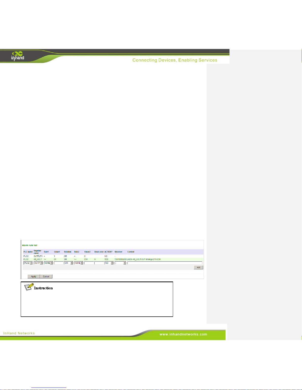
Below is an example of an alarm rule:
The first rule states that when the OUTPUT1 of plc2 changes from 1 to 0 or from 0
to 1, trigger the alarm and send the alarm SMS to all users in
the “alarm user list.”
Page 53
53 / 92
The second rule states that when the variable value of AB_VOLT in plc2 is less
than or equal to 20 or greater than or equal to 230, trigger the
alarm and send the user-define SMS to the user ‘13810556243.’
In other words, when AB_VOLT is between 20 and 230, plc2 is
in normal operating conditions.
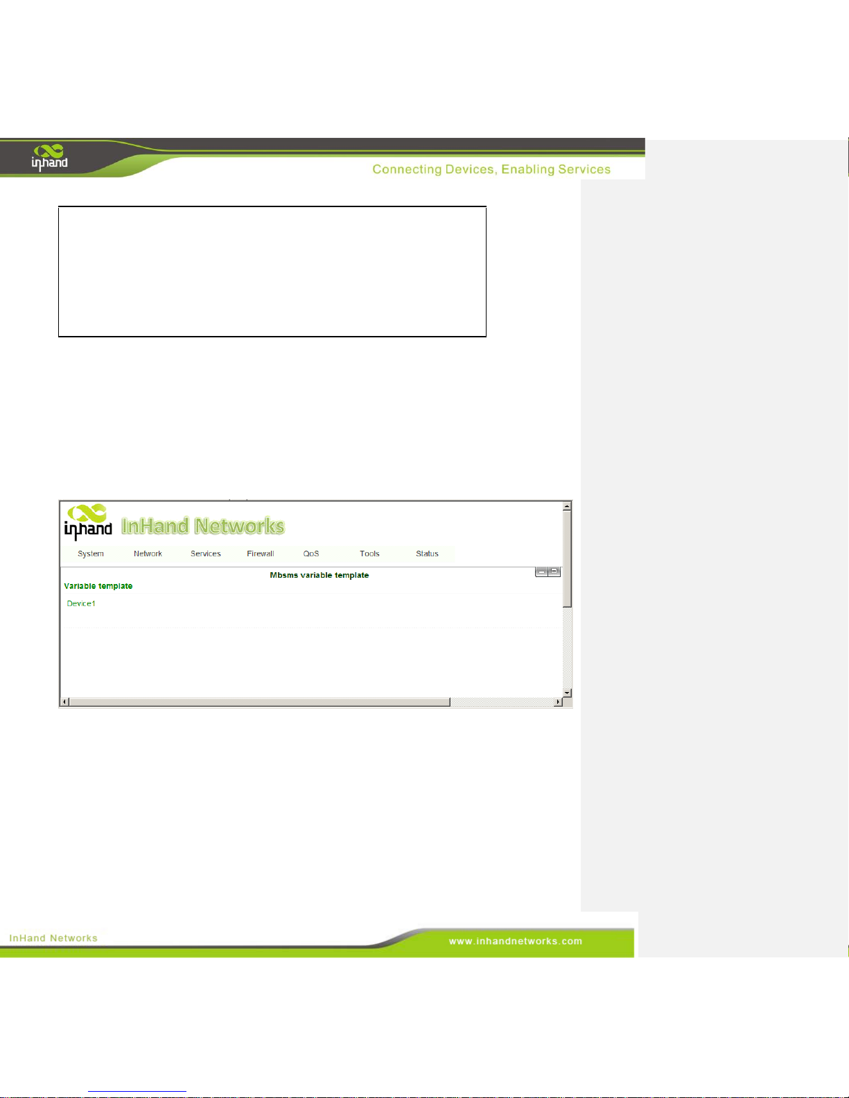
3.4.8 Mbsms Variable Template
Users can download a PLC variable template file which you might have added in section 3.3 “Modbus
to SMS.” A template file is composed of all the variables in a PLC, and the IG601 supports up to eight
templates.
To configure the Mbsms template, go into the navigation panel, select Services >> Mbsms Variable
Template, then enter “Variable Template” page, which is shown below.
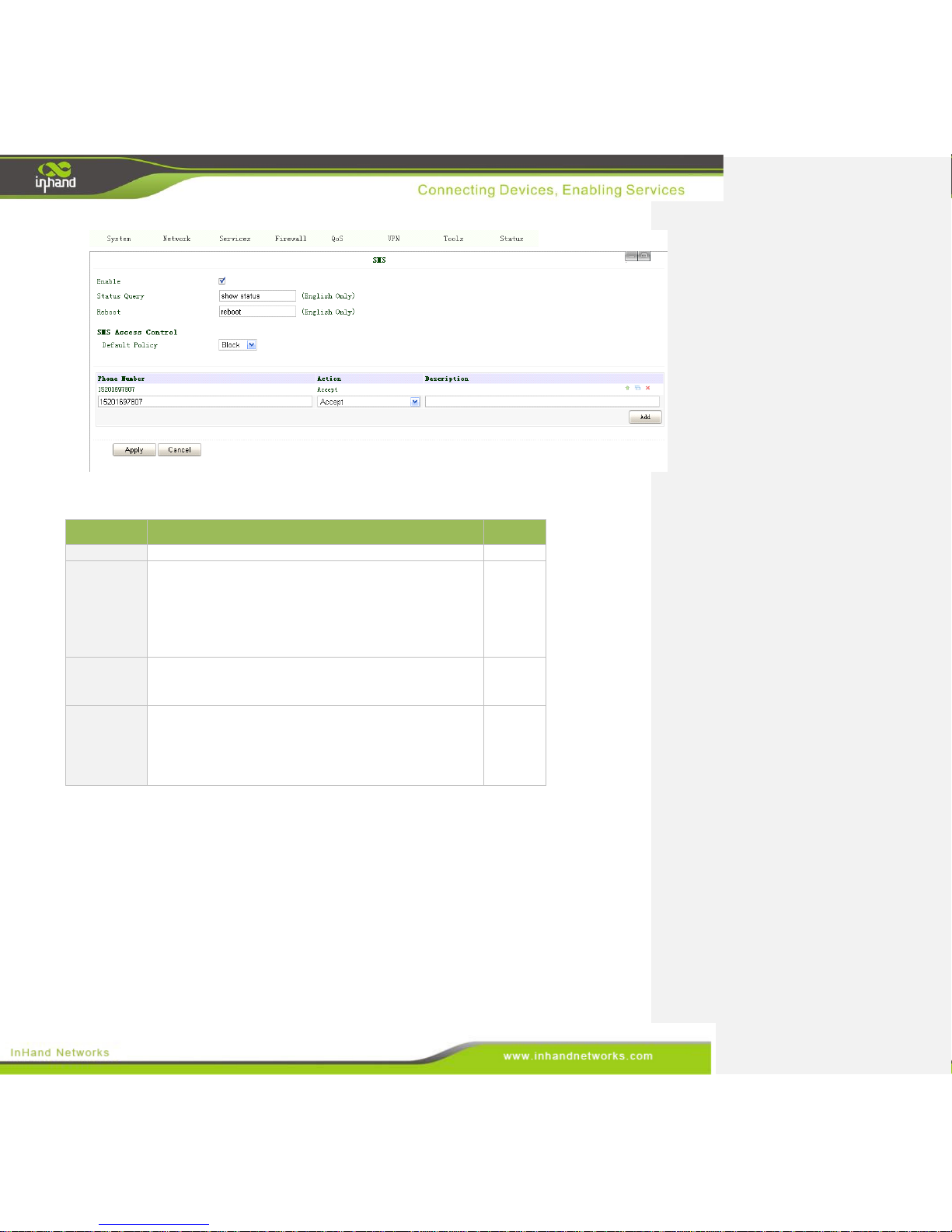
3.4.9 SMS
User can do a status check and reboot the IG601 through SMS. After setting a user-defined message in
the SMS config window, users can see the device's status or reboot the device. Statistics like signal
strength, IP address, and uptime, among others, may be used to analyze the device.
To configure SMS, find the navigation panel, select Services >> SMS, then enter “SMS” page, as
shown below.
Page 54
54 / 92
The page description is shown below:
Parameters
Description
Default
Enable
Click to enable SMS.
Disable
Status
Query
This is user defined. After configuration, the user sends
the predetermined message to IG601, which will send
status information to user’s mobile phone.
The information include :Host: (SN); Uptime: (the uptime
of router for this time of reboot); State: (Online/Offline);
LAN: (Up) (LAN IP)
N/A
Reboot
This is user defined as well. After configuration, the user
will send a user-defined message to the IG601 which will
then restart.
N/A
Default
Policy
This accepts by default. If the mobile phone number is
empty, the IG601 will execute the SMS command from
any mobile phone number. If a phone number is entered
into the field, the IG601 will execute SMS commands
from the configured mobile phone number.
Accept
3.5 Firewall
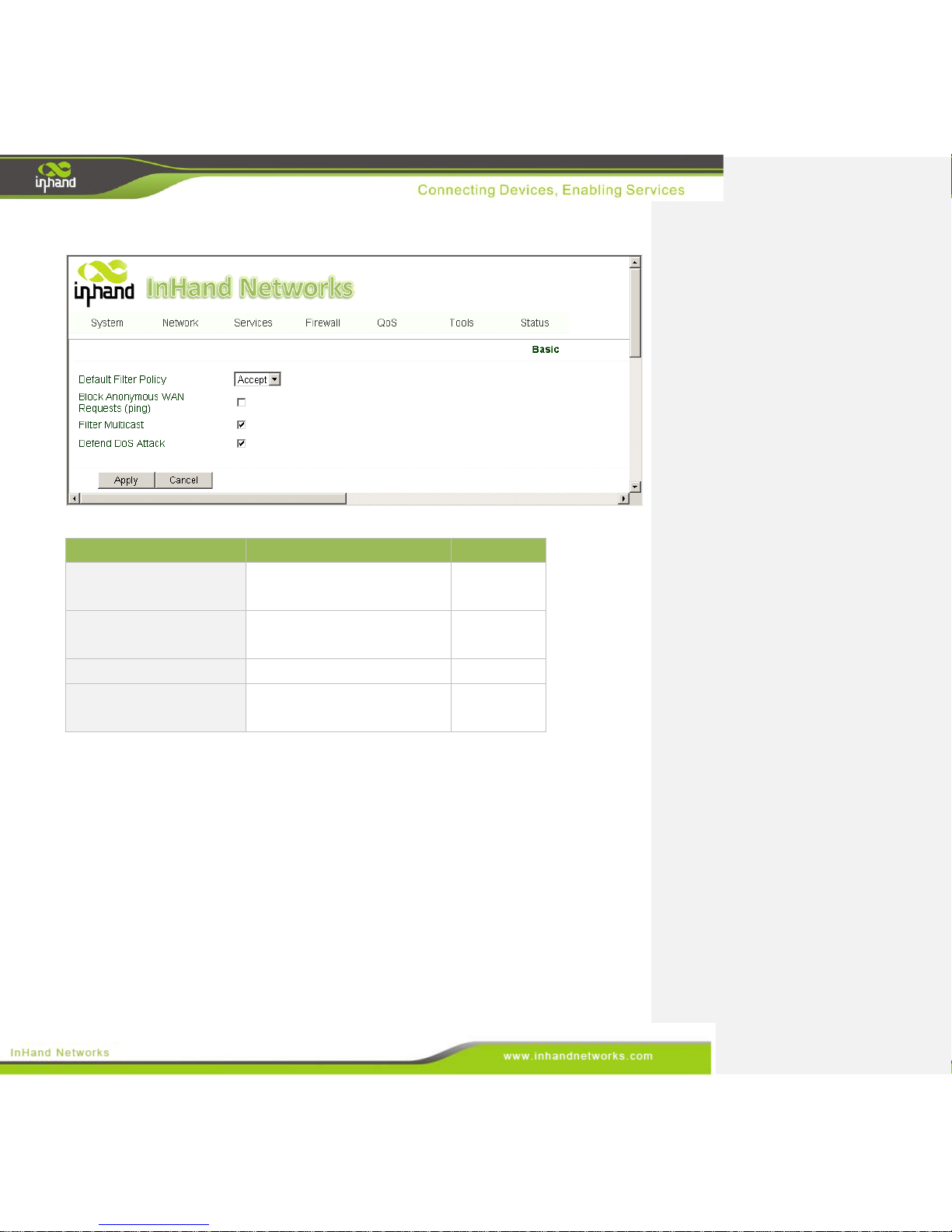
3.5.1 Basic
A firewall is necessary for blocking out malicious packets from the internet. On today's internet,
security is more important than ever, which is why the IG601 is well equipped to protecting the local
network and provide a security barrier from external threats.
To configure the firewall, go to the navigation panel, select Firewall >> Basic, then enter the “Basic”
Page 55
55 / 92
config page, as shown below.
The page description is shown below:
Parameters
Description
Default
Default Filter Policy
Choose to either “Accept” or
“Block” filtering.
Accept
Block Anonymous WAN
Request (ping)
Check to deny anonymous ICMP
ping requests.
Disable
Filter Multicast
Check to filter multicast packets.
Enable
Defend DoS Attack
Select to enable DoS attack
prevention.
Enable
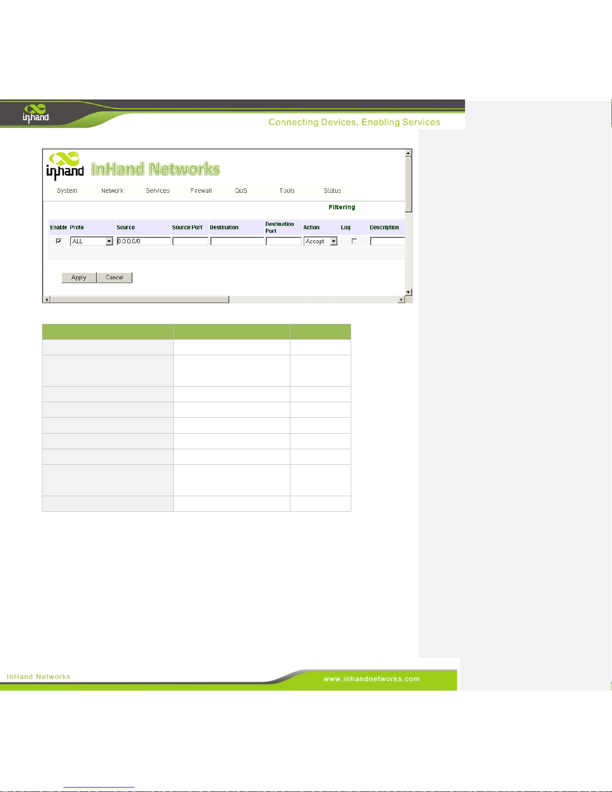
3.5.2 Filtering
Access control has the following functions:
Prevent unwanted users from accessing network resources.
Permitting staff to access network resources.
Preventing staff from accessing the wrong network resources.
To enable Access Control From the navigation panel, select Firewall >> Filtering, then enter
“Filtering” page, as shown below.
Page 56
56 / 92
Page description is shown below:
Parameters
Description
Default
Enable
Check to enable filtering.
Enable
Protocol
The available options are:
TCP, UDP, ICMP, and all.
All
Source IP address
Set the source IP address.
0.0.0.0/0
Source Port
Set the source port.
N/A
Destination IP
Set the destination IP address.
N/A
Destination Port
Set the destination port.
N/A
Action
Select either accept or block.
Accept
Log
log can print the access IP
address
Disable
Description
Describe your configuration.
N/A
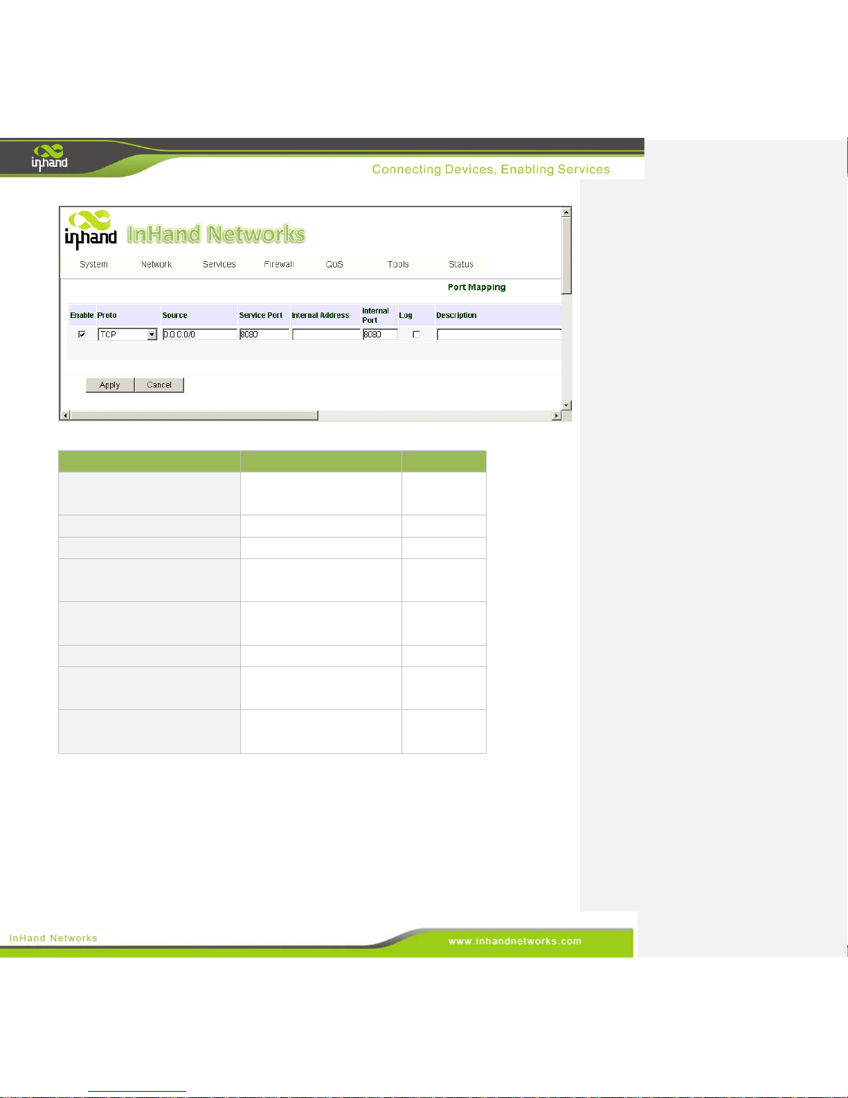
3.5.3 Port Mapping
The IG601 support Network Address and Port Translation. It allows remote computers (for example,
computers on the Internet) to connect to the local device that linked to LAN interface.
To configure port mapping, go into the navigation panel, select Firewall >> Port Mapping, then enter
“Port Mapping” page, as shown below.
Page 57
57 / 92
Page description is shown below:
Parameters
Description
Default
Enable
Check to enable port
mapping.
Enable
Protocol
Select either TCP or UDP.
TCP
Source
Set an external source IP.
0.0.0.0/0
Service Port
Set the external port of
service.
8080
Internal Address
Set the internal IP for
mapping.
Blank
Internal Port
Set the mapping port.
8080
Log
Click to enable a log about
port mapping.
Disable
Description
Write a description to avoid
future confusion.
Blank
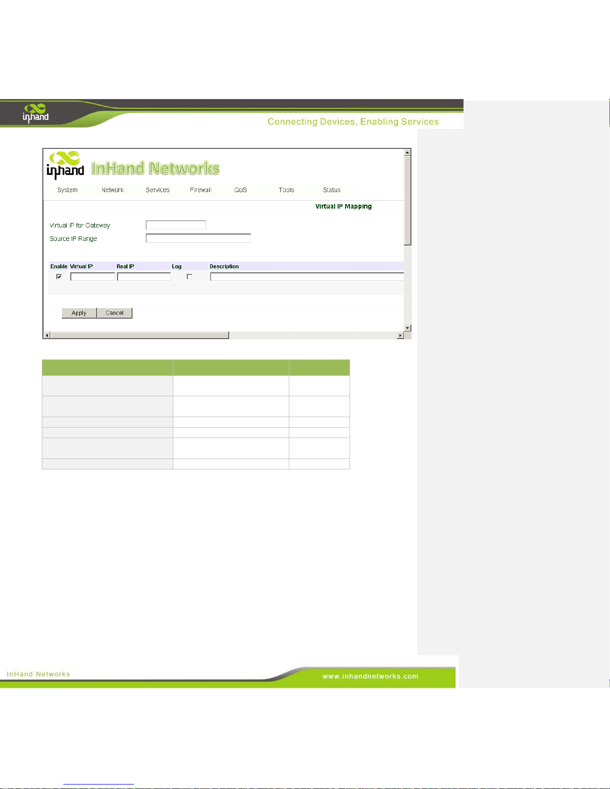
3.5.4 Virtual IP Mapping
After a PC in LAN has been assigned a virtual IP, external hosts can access it via a virtual IP.
The functions usually work with VPN.
To enable virtual IP mapping, go into the navigation panel, select Firewall >> Virtual IP Mapping,
then enter the “Virtual IP Mapping” page, as shown below.
Page 58
58 / 92
Page description is shown below:
Parameters
Description
Default
Virtual IP for Gateway
Set a virtual IP for the
InGateway.
Blank
Source IP Range
Set range of the external
source IP addresses.
Blank
Virtual IP
Set an external virtual IP.
Blank
Real IP
Set a real IP.
Blank
Log
Enable a log of virtual IP
events.
Disable
Description
Describe this configuration.
Blank
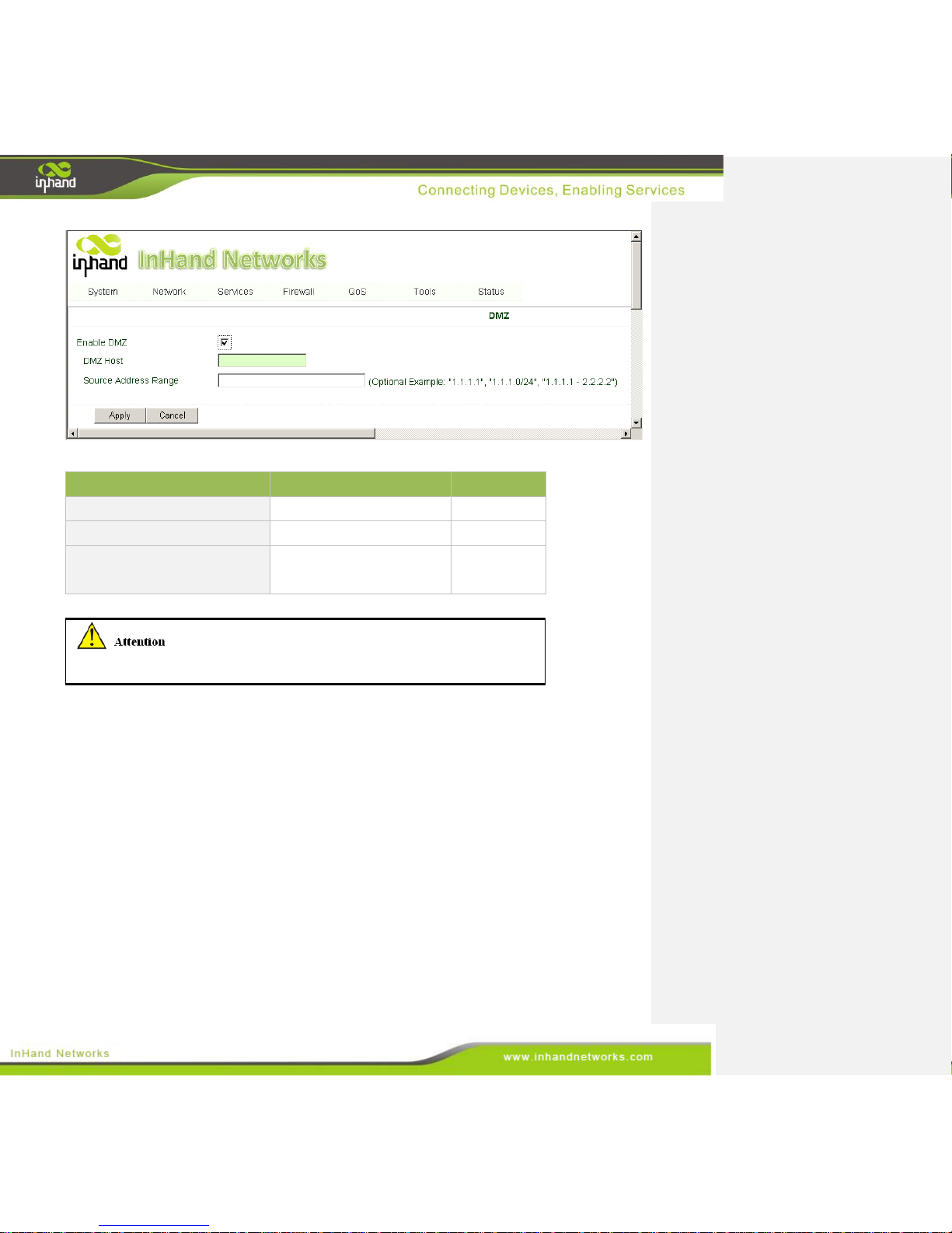
3.5.5 DMZ (All Port Mapping)
DMZ is like a virtual server, the all port of router map to the DMZ host
From the navigation panel, select Firewall >> DMZ, then enter “DMZ” page, as shown below.
Page 59
59 / 92
The page description is shown below:
Parameters
Description
Default
Enable DMZ
Check to enable the DMZ.
Disabled
DMZ Host
Set the host IP of a DMZ.
Blank
Source Address Range
Set a range of restricted
source IP addresses.
Blank
The IG601's management port should never be mapped to a DMZ.
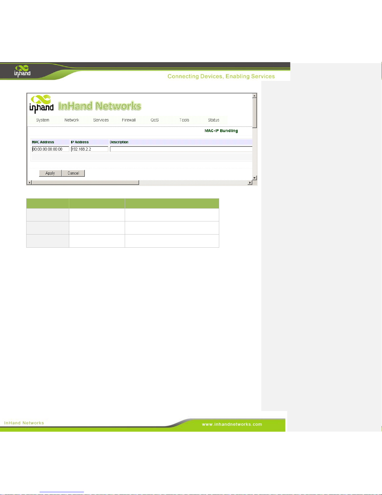
3.5.6 MAC-IP Bundling
When a firewall denies all access to the external network, only a PC with MAC-IP bundling can access
the internet.
From the navigation panel, select Firewall >> MAC-IP Bundling, then enter the “MAC-IP Bundling”
page, as shown below.
Page 60
60 / 92
The page description is shown below:
Parameters
Description
Default
MAC Address
Set the bundling PC's
mac address.
00:00:00:00:00:00
IP Address
Set the bundling PC's
IP address.
192.168.2.2
Description
Describe this
configuration.
Blank
3.6 QoS
This chapter covers QoS, or Quality of Service. QoS is a set of services that ensures bandwidth
availability for sensitive applications. These services includes bandwidth control and IP bandwidth
limits.
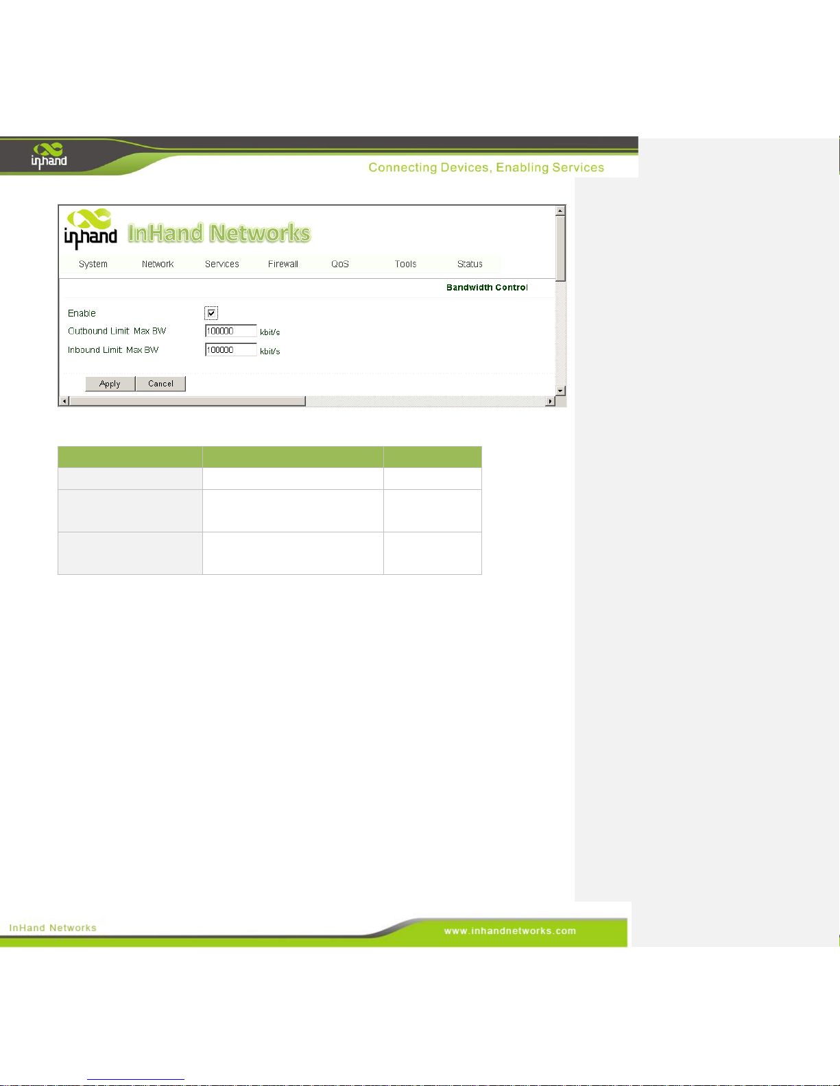
3.6.1 Bandwidth Control
Bandwidth control set a limit on the upload and dowload speeds when accessing external networks.
To configure bandwidth control, go into the navigation panel, select QoS >> Bandwidth Control, then
enter “Bandwidth Control” page, as shown below.
Page 61
61 / 92
The page description is shown below:
Parameters
Description
Default
Enable
Check to enable.
Disable
Outbound Limit Max
Bandwidth
Set the maximum upload rate.
100000kbit/s
Inbound Limit Max
Bandwidth
Set the download bandwidth limit.
100000kbit/s
3.6.2 IP Bandwidth Limit
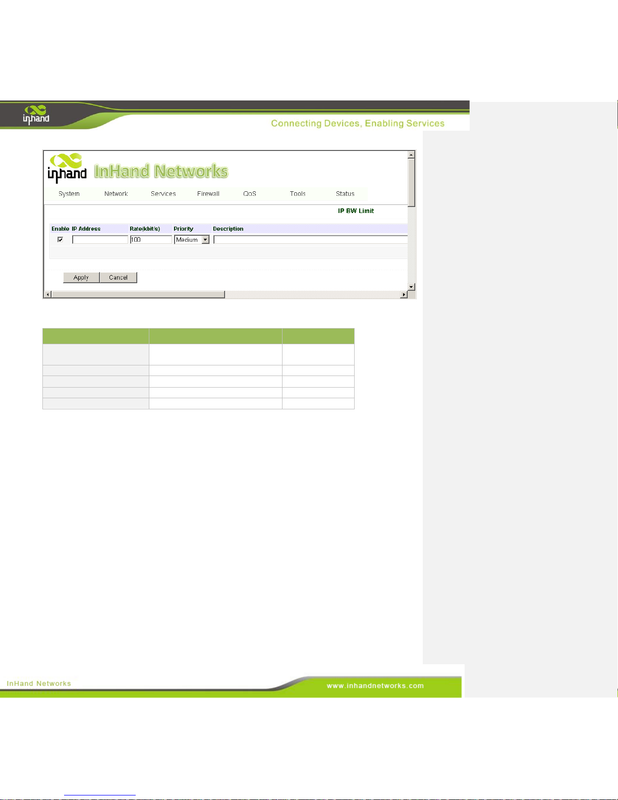
Technicians may limit the bandwidth on individual hosts and devices by setting IP based bandwidth
limits.
To configure the IP bandwidth limit, go to the navigation panel, select Firewall >> IP BW Limit, and
then enter the “IP BW Limit” page, as shown below.
Page 62
62 / 92
The page description is shown below:
Parameters
Description
Default
Enable
Check to enable an IP bandwidth
limiter.
Enable
IP Address
Set the IP address to be limited.
N/A
Rate(kbit/s)
Set the bandwidth limit or rate.
100kbit/s
Priority
Set the priority.
Medium
Description
Describe the configuration.
N/A
3.7 Tools
The IG601 comes with several tools to help admins diagnose network problems, including:
• Ping
• Trace route
• Link Speed Test
3.7.1 Ping
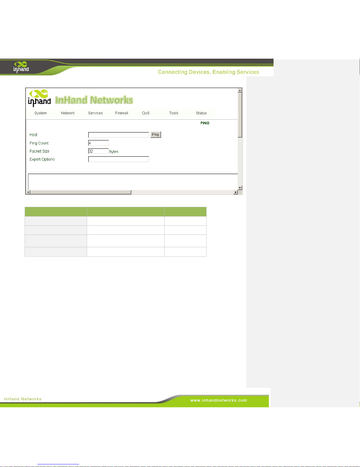
Ping a tool many technicians are familiar with. It simply sends ICMP packets across the network to a
remote host, and then retransmits an ICMP packet back to the original sender.
To do a ping, enter the navigation panel, select Tools>>Ping, then enter the “Ping” page, as shown
below.
Page 63
63 / 92
Page description is shown below:
Parameters
Description
Default
Host
Destination IP for the ping.
N/A
Ping Count
Number of pings sent.
4 times
Packet Size
The size of the ping packet sent.
32B is recommended.
32 Bytes
Expert Options
Advanced parameters
N/A
3.7.2 Trace Route
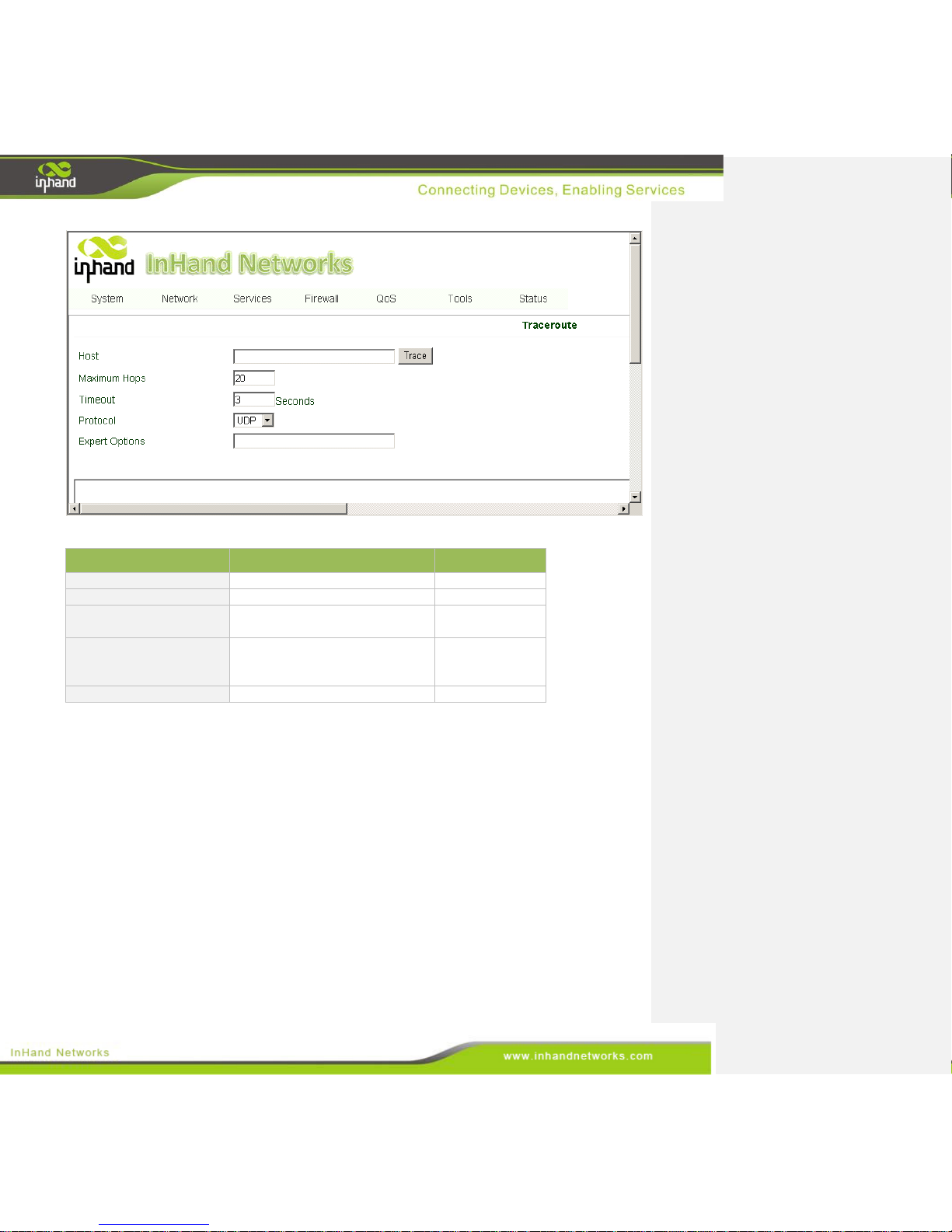
The trace route tool sends an ICMP or UDP packet to a remote host. Each time the packet is routed
onto a different network, that router will return a response. Trace route allows network engineers to
diagnose routing problems.
To preform a trace route, go to the navigation panel, select Tools>>Traceroute, then scroll down to the
“Traceroute” page, as shown below.
Page 64
64 / 92
The page description is shown below:
Parameters
Description
Default
Host
The destination for trace route.
N/A
Max Hops
Set the maximum number of hops.
20
Time Out
Set the timeout for dropped
packets.
3 sec
Protocol
Choose between ICMP and UDP
protocol. ICMP may be blocked
on some networks.
UDP
Expert Options
Advanced parameters
N/A
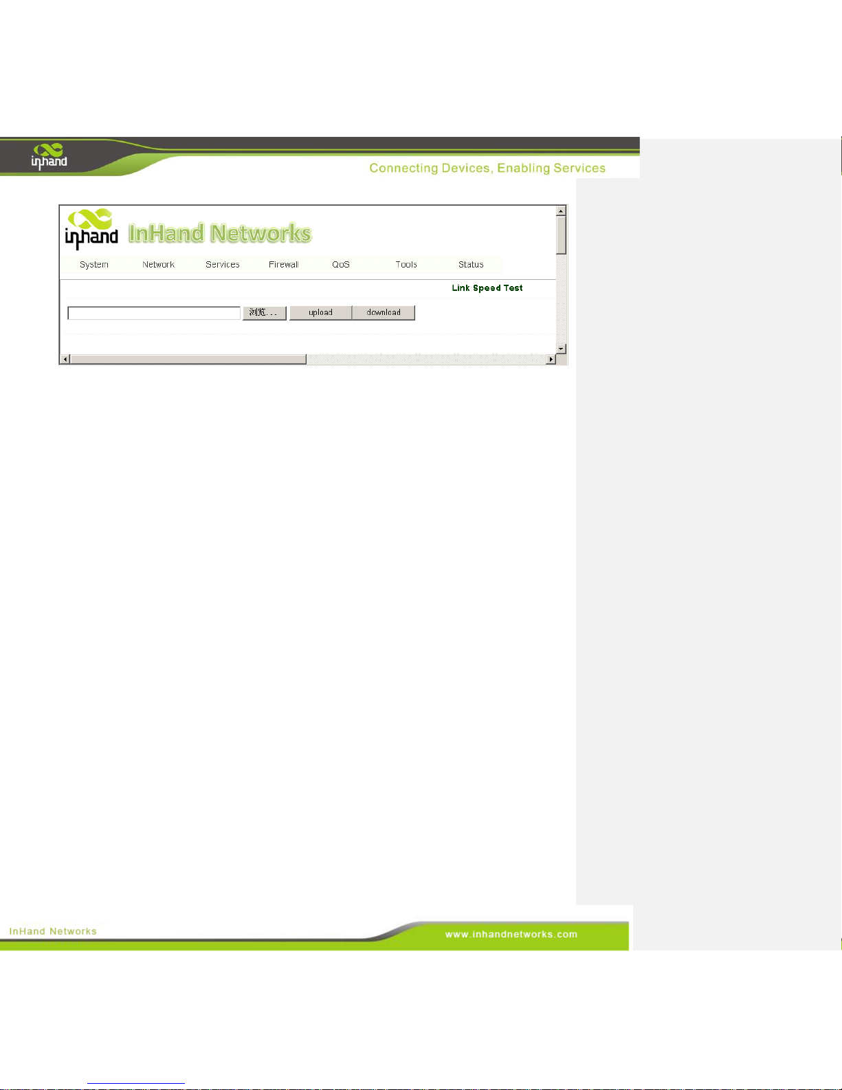
3.7.3 Link Speed Test
The IG601 uses a simple upload and download to test the link speed.
To start the speed test, enter the navigation panel, select Tools>>Link Speed Test, then enter “Link
Speed Test” page, as shown below.
Page 65
65 / 92
3.8 Status
The status chapter covers the following:
• System
• Modem
• Network Connections
• Routing Table
• Device List
• ModbusPLC
• Event Logs
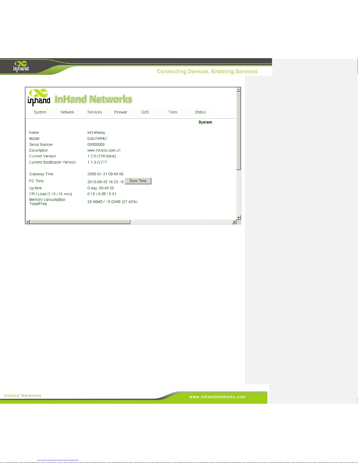
3.8.1 System
From navigation panel, select Status >> System, then enter the “System” page, as shown below. This
page displays system statistics, including Name, Model, Current Version, Gateway Time, PC Time, UP
Time, CPU Load, Memory Consumption, etc. Technicians may click the <Sync Time> button to
synchronize the gateway with the system time of the host, as covered in the set-up chapter.
Page 66
66 / 92
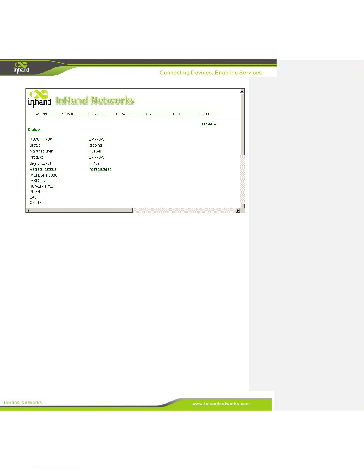
3.8.2 Modem
From navigation panel, select Status >> Modem, then enter “Modem” page, as shown below. This
page shows Modem status, including Signal Level, Register status, etc.
Page 67
67 / 92
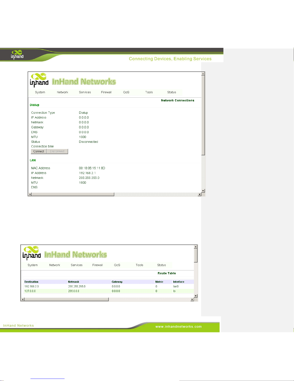
3.8.3 Network Connections
From navigation panel, select Status >> Network Connections, then enter “Network Connections”
page, as shown below. This page shows the connection status of Dialup and LAN.
Page 68
68 / 92
3.8.4 Route Table
From navigation panel, select Status >> Route Table, then enter “Route Table” page, as shown below.
This page shows the route table of IG601.
Page 69
69 / 92
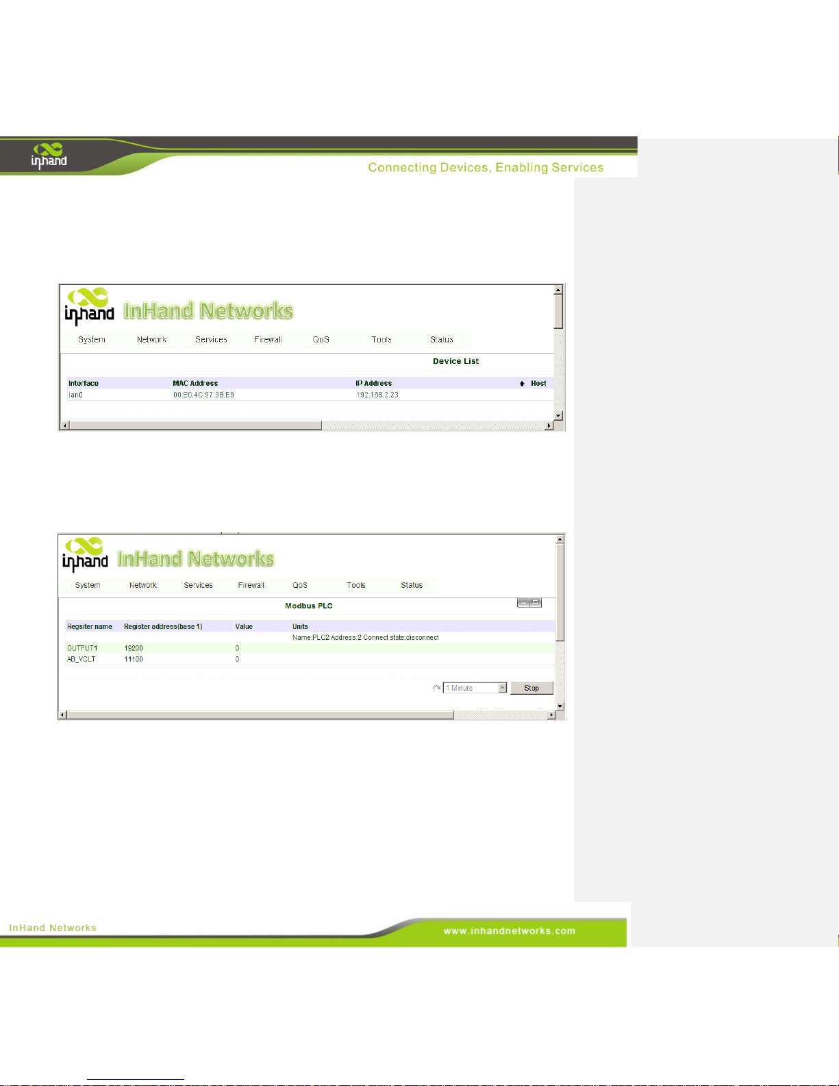
3.8.5 Device List
From navigation panel, select Status >> Device List, then enter “Device List” page, as shown below.
This page shows the device link of IG601.
3.8.6 Modbus PLC
From navigation panel, select Status >> Modbus PLC, then enter “Modbus PLC” page, as shown
below. This page shows the parameters of Modbus PLC linked with IG601.
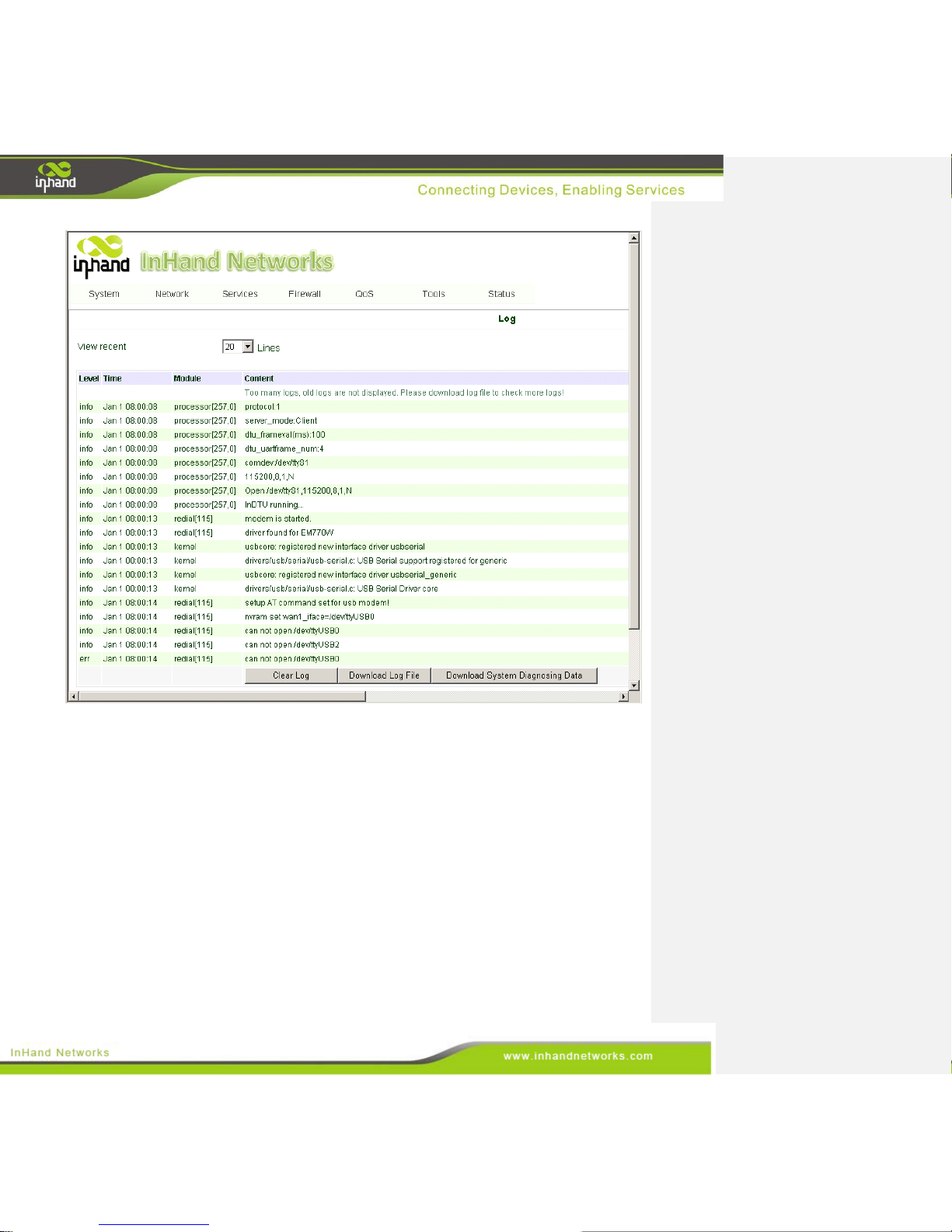
3.8.7 Log
From navigation panel, select Status >> Log, then enter “Log” page, as shown below. This page show
system log, including Download Log File.
Page 70
70 / 92
3.9 VPN
VPN is a new technology that rapidly developed in recent years with the extensive application of
Internet. It is for building a private dedicated network on a public network. 'Virtuality" mainly refers to
that the network is a logical network.
Two Basic Features of VPN:
Private: the resources of VPN are unavailable to unauthorized VPN users on the internet; VPN can
ensure and protect its internal information from external intrusion.
Virtual: the communication among VPN users is realized via public network which, meanwhile can
be used by unauthorized VPN users so that what VPN users obtained is only a logistic private
network. This public network is regarded as VPN Backbone.
Page 71
71 / 92
Fundamental Principle of VPN
The fundamental principle of VPN indicates to enclose VPN message into tunnel with tunneling
technology and to establish a private data transmission channel utilizing VPN Backbone so as to realize
the transparent message transmission.
Tunneling technology encloses the other protocol message with one protocol. Also, encapsulation
protocol itself can be enclosed or carried by other encapsulation protocols. To the users, tunnel is
logical extension of PSTN/link of ISDN, which is similar to the operation of actual physical link.
3.9.1 IPSec
To build IPSec VPN tunnels, users need to set up IPSec and then add VPN tunnels.
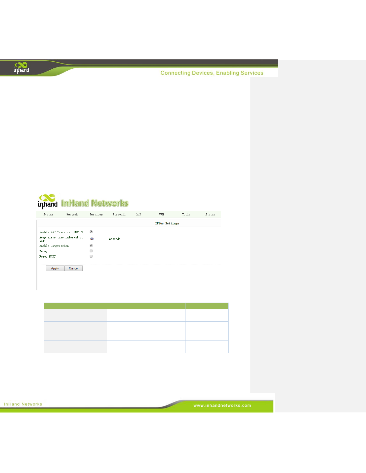
3.9.1.1 IPSec Settings
From navigation panel, select VPN>>IPSec, then enter “IPSec Settings” page, as shown below.
Page description is shown below:
Parameters
Description
Default
Enable NAT-Traversal
(NATT)
Normally enable NATT; unless
there is no NAT routing
Enable
Keep alive time interval of
NATT
Set alive time interval
60 seconds
Enable Compression
Click to enable
Enable
Debug
Click to enable
Disable
Force NATT
Click to enable
Disable
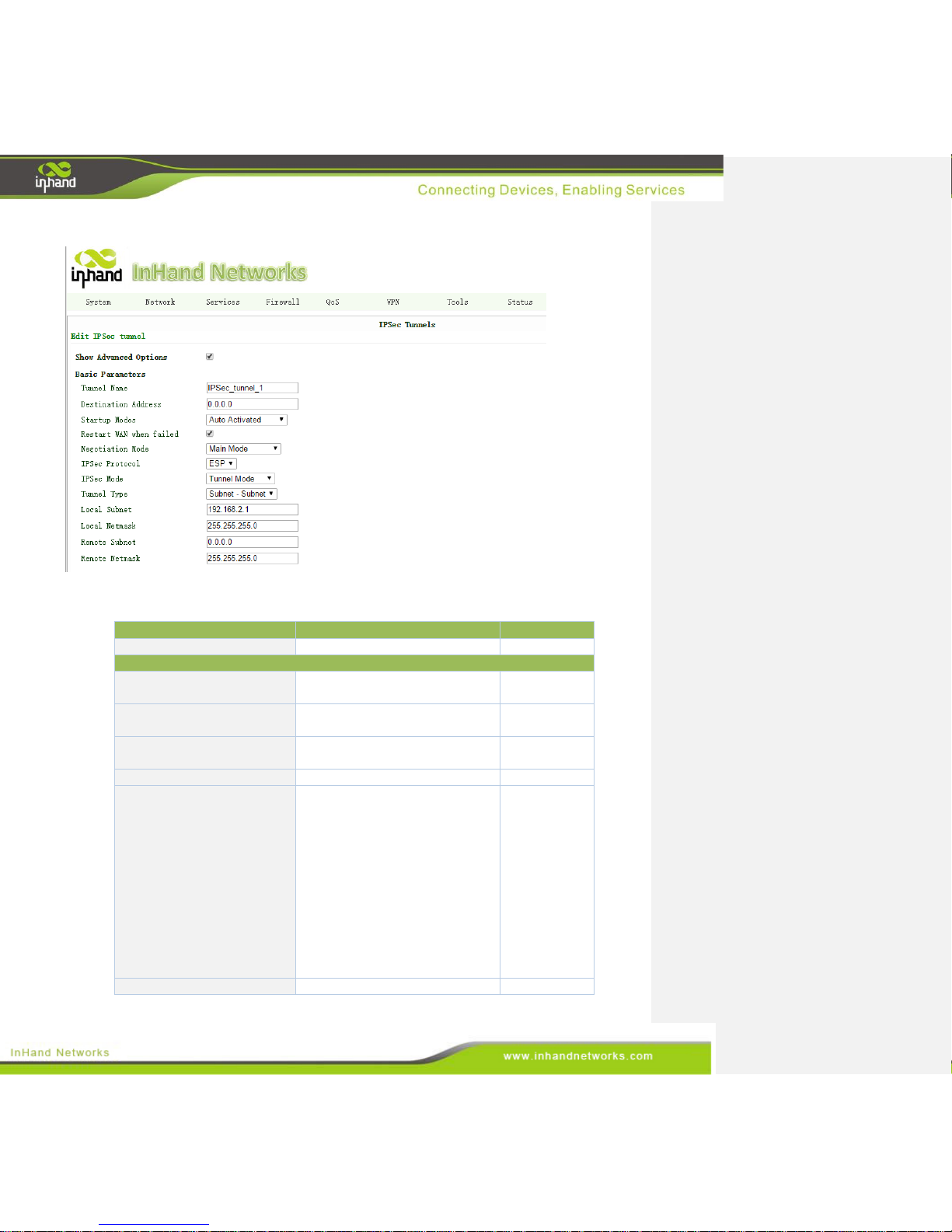
3.9.1.2 IPSec Tunnels
From navigation panel, select VPN>>IPSec Tunnels, click <add>, as shown below.
Page 72
72 / 92
Page description is shown below:
Parameters
Description
Default
Show Advanced Options
Advanced Options
Disable
Basic Parameters
Tunnel Name
Name the tunnel
IPSec_tunnel_
1
Destination Address
Set the destination address of
IPSec VPN server
0.0.0.0
Startup Modes
Auto Activated/Triggered by
Data/Passive/Manually Activated
Auto
Activated
Restart WAN when failed
Click to enable
Enable
Negotiation Mode
Main mode: as an exchange
method of IKE, main mode shall
be established in the situation
where stricter identity protection
is required.
Aggressive mode: as an exchange
method of IKE, aggressive mode
exchanging fewer message, can
accelerate negotiation in the
situation where there is no strict
requirement on identity
protection.
Main Mode
IPSec Protocol (Enable
AH: protect integrity and
ESP
Page 73

73 / 92
Advanced Options)
authenticity of data packet from
hacker intercepting data packet or
inserting false data packet on the
internet.
ESP: encrypt the user data
needing protection, and then
enclose into IP packet for the
purpose of confidentiality of data.
IPSec Mode (Enable
Advanced Options)
Tunnel Mode: besides source
host and destination host, special
gateway will be operated with
password to ensure the safety
from gateway to gateway.
Transmission Mode: source host
and destination host must directly
execute all passwords operations
for the purpose of higher work
efficiency, but comparing with
tunnel mode the security will be
inferior.
Tunnel Mode
Tunnel Type
Host-Host, Host-Subnet, SubnetHost, Subnet-Subnet
Subnet-Subnet
Local Subnet
Set local subnet
192.168.2.1
Local Netmask
Set local netmask
255.255.255.0
Remote Subnet
Set remote subnet
0.0.0.0
Remote Netmask
Set remote netmask
255.255.255.0
Phase 1 Parameters
IKE Policy
Select IKE policy
3DES-MD5-
DH2
IKE Lifetime
Set IKE lifetime
86400
seconds
Local ID Type
FQDN/ User FQDN/IP
IP address
Remote ID Type
FQDN/User FQDN/ IP
IP address
Authentication Type
Shared Key or Certificate
Shared Key
Key (only for Shared Key)
Set IPSec VPN key
N/A
Phase 2Parameters
IPSec Policy
Select IKE policy
3DES-MD5-
96
IPSec Lifetime
Set IKE lifetime
3600 seconds
Perfect Forward Secrecy
(PFS)
The exposure of one key will not
affect the data security protected
by other keys.
Disable
Link Detection Parameters
DPD Interval
Used for detection interval of
IPSec neighbor state.
After initiating DPD, If receiving
60 seconds
Page 74
74 / 92
end can not receive IPSec
cryptographic message sent by
peer end within interval of
triggering DPD, receiving end can
make DPD check, send request
message to opposite end
automatically, detect whether IKE
peer pair exists.
DPD Timeout
Receiving end will make DPD
check and send request message
automatically to opposite end for
check. If it does not receive IPSec
cryptographic message from peer
end beyond timeout, ISAKMP
Profile will be deleted.
180 seconds
ICMP Detection Server
Set ICMP detection derver
N/A
ICMP Detection Local IP
Set ICMP detection local IP
N/A
ICMP Detection Interval
Set ICMP detection interval
60 seconds
ICMP Detection Timeout
Set ICMP detection timeout
5 seconds
ICMP Detection Max Retries
Set the max number of retries if
ICMP failed
10
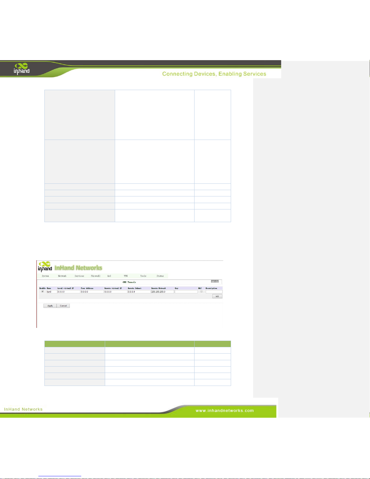
3.9.2 GRE Tunnels
From navigation panel, select VPN>>GRE then enter “GRE Tunnels” page, as shown below.
After basic settings, click <Add>.
Page description is shown below:
Parameters
Description
Default
Enable
Click to enable
Enable
Name
Set GRE tunnel name
tun0
Local virtual IP
Set local virtual IP
0.0.0.0
Peer address
Set peer address
0.0.0.0
Remote virtual IP
Set remote virtual IP
0.0.0.0
Remote Subnet
Set remote subnet
0.0.0.0
Page 75
75 / 92
Remote Netmask
Set remote netmask
255.255.255.0
Key
Set tunnel key
N/A
NAT
Click to enable NAT
Disable
Description
Add description
N/A
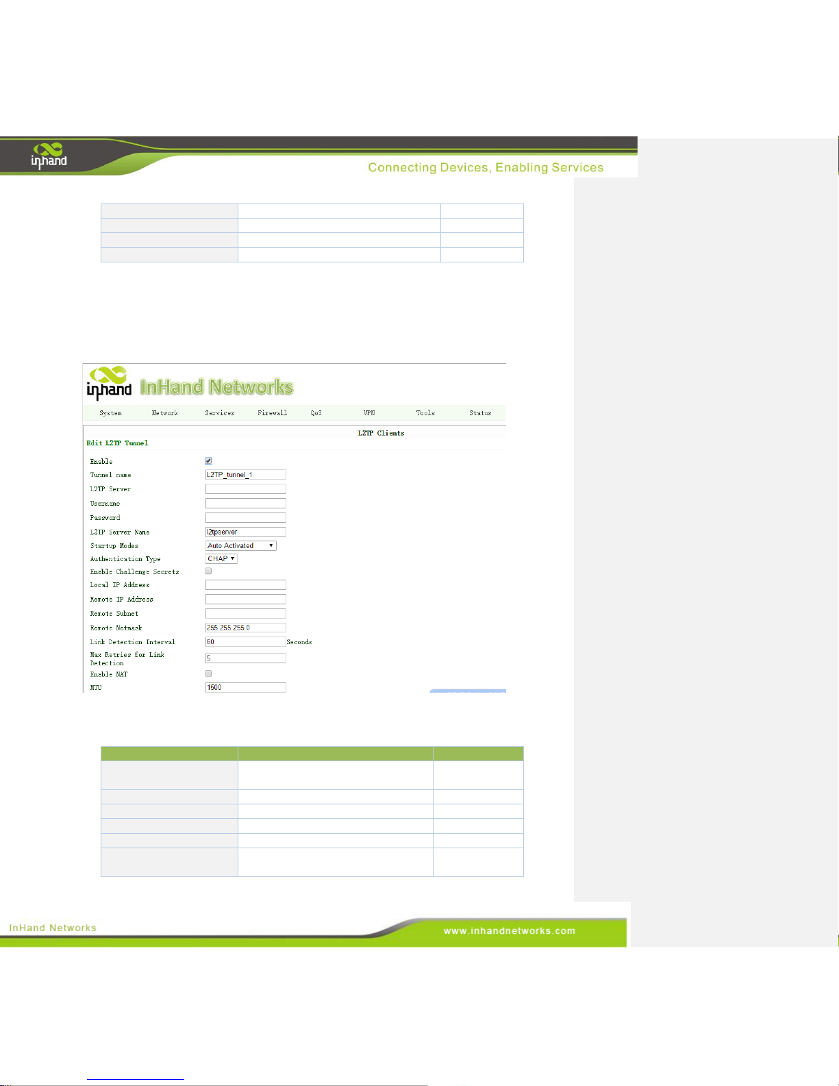
3.9.3 L2TP Client
From navigation panel, select VPN>>L2TP, then enter “L2TP Clients” page, click <Add> and
enter “Edit L2TP Tunnel” page, as shown below.
Page description is shown below:
Parameters
Description
Default
Tunnel name
Set tunnel name
L2TP_TUNNE
L_1
L2TP Server
Set server address
N/A
Username
Set username
N/A
Password
Set password
N/A
L2TP Server Name
Set server name
l2tpserver
Startup Mode
Auto Activated/Triggered by
Data/Manually Activated
Auto Activated
Page 76
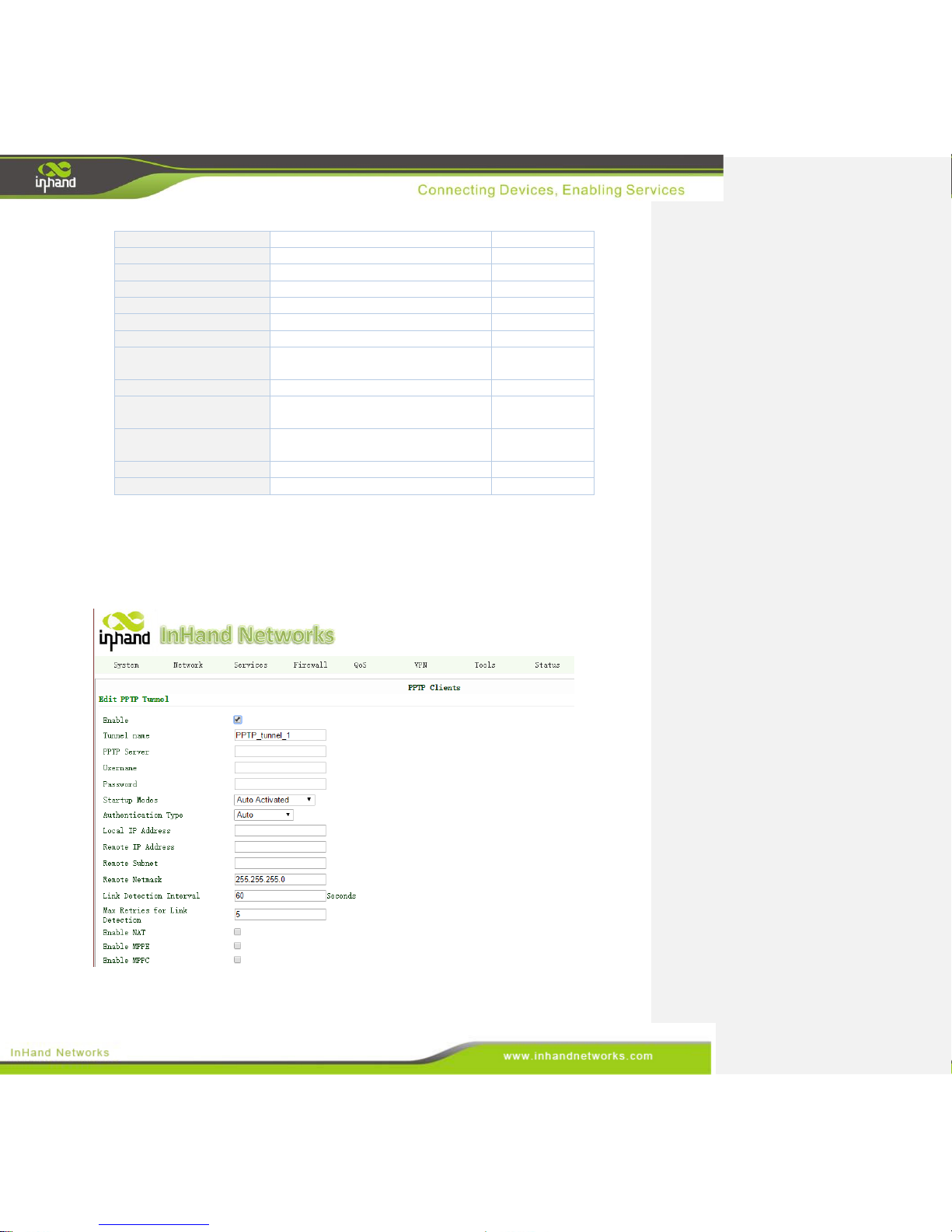
76 / 92
Authentication Type
CHAP or PAP
CHAP
Enable Challenge secrets
Click to enable
Disable
Local IP Address
Set local IP address
N/A
Remote IP Address
Set remote IP address
N/A
Remote Subnet
Set remote subnet
N/A
Remote Netmask
Set remote netmask
255.255.255.0
Link Detection Interval
Set link detection interval
60
Max Retries for Link
Detection
Set the max number of retries
5
Enable NAT
Click to enable
Disable
MTU
Set maximal transmission unit, unit
in byte
1500
MRU
Set maximal receiving unit, unit in
byte
1500
Enable Debug
Click to enable
Disable
Expert Options
Set expert options
N/A
3.9.4 PPTP Client
From navigation panel, select VPN>>PPTP, then enter “PPTP Clients” page, click <Add> and
enter “Edit PPTP Tunnel” page, as shown below.
Page description is shown below:
Page 77

77 / 92
Parameters
Description
Default
Tunnel name
Set tunnel name
PPTP_tunnel_1
PPTP Server
Set PPTP server address
N/A
Username
Set username
N/A
Password
Set password
N/A
Startup Mode
Auto Activated/Triggered by
Data/Manually Activated
Auto Activated
Authentication Type
Auto/CHAP/PAP/ MS-CHAPv1/
MS-CHAPv2
Auto
Local IP Address
Set local IP address
N/A
Remote IP Address
Set remote IP address
N/A
Remote Subnet
Set remote subnet
N/A
Remote Netmask
Set remote netmask
255.255.255.0
Link Detection Interval
Set link detection interval
60 seconds
Max Retries for Link
Detection
Set the max number of retries
5
Enable NAT
Click to enable
N/A
Enable MPPE
Click to enable
N/A
Enable MPPC
Click to enable
N/A
MTU
Set maximal transmission unit, unit
in byte
1500
MRU
Set maximal receiving unit, unit in
byte
1500
Enable Debug
Click to enable
N/A
Expert Options
For InHand R&D team
N/A
3.9.5 OpenVPN
3.9.5.1 OpenVPN
From navigation panel, select VPN>>OpenVPN, then enter “OpenVPN Tunnels” page, click
<Add> and enter “Edit OpenVPN Tunnel” page, as shown below.
Page 78
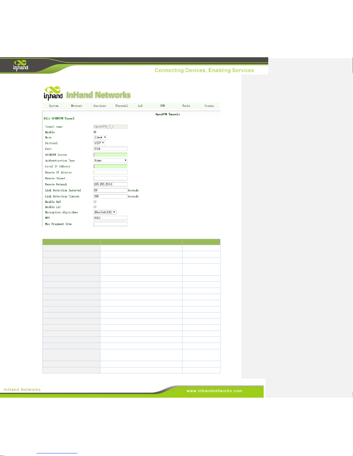
78 / 92
Page description is shown below:
Parameters
Description
Default
Tunnel name
Set tunnel name
OpenVPN_T_1
Enable
Click to enable
Enable
Mode
Client or Server
Client
Protocol
Same with the protocol of remote
server
UDP
Port
Input port
1194
OPENVPN Server
Input remote server IP address
N/A
Authentication Type
Select type
None
Local IP Address
Set local IP address
N/A
Remote IP Address
Set remote IP address
N/A
Remote Subnet
Set remote subnet
N/A
Remote Netmask
Set remote netmask
255.255.255.0
Link Detection Interval
Set link detection interval
60 seconds
ICMP Detection Timeout
Set ICMP detection timeout
300 seconds
Enable NAT
Click to enable
Disable
Enable LZO
Click to enable
Disable
Encryption Algorithms
Same with the server
Blowfish(128)
MTU
Set maximal transmission unit, unit
in byte
1500
Max Fragment Size
Set max fragment size
N/A
Debug Level
Set debug level
Warn
Page 79
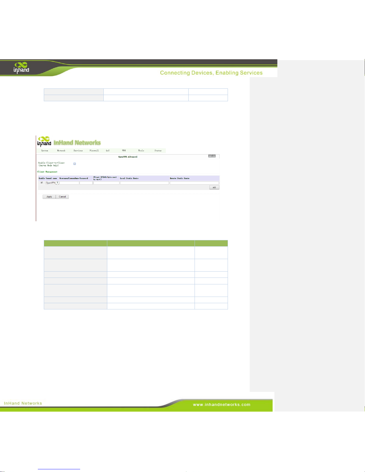
79 / 92
Interface Type
TUN-data packet, TAP-data frame
TUN
Expert Options
For InHand R&D team
N/A
3.9.5.2 OpenVPN Advanced
From navigation panel, select VPN>>OpenVPN Advanced, then enter “OpenVPN Advanced”
page, click <Add> and click <Apply>, as shown below.
Page description is shown below:
Parameters
Description
Default
Enable Client-Client
(Server Mode Only)
Available only user server mode
Disable
Tunnel Name
Set tunnel name
OpenVPN_T
_1
Username/CommonName
User define
N/A
Password
User define
N/A
Client IP (4th byte must be
4n+1)
Set client IP
N/A
Local Static Route
Set static route from server to client
N/A
Remote Static Route
Set static route from client to server
N/A
3.9.6 Certificate Management
From navigation panel, select VPN>> Certificate Management, then enter “Certificate
Management” page, as shown below.
Page 80
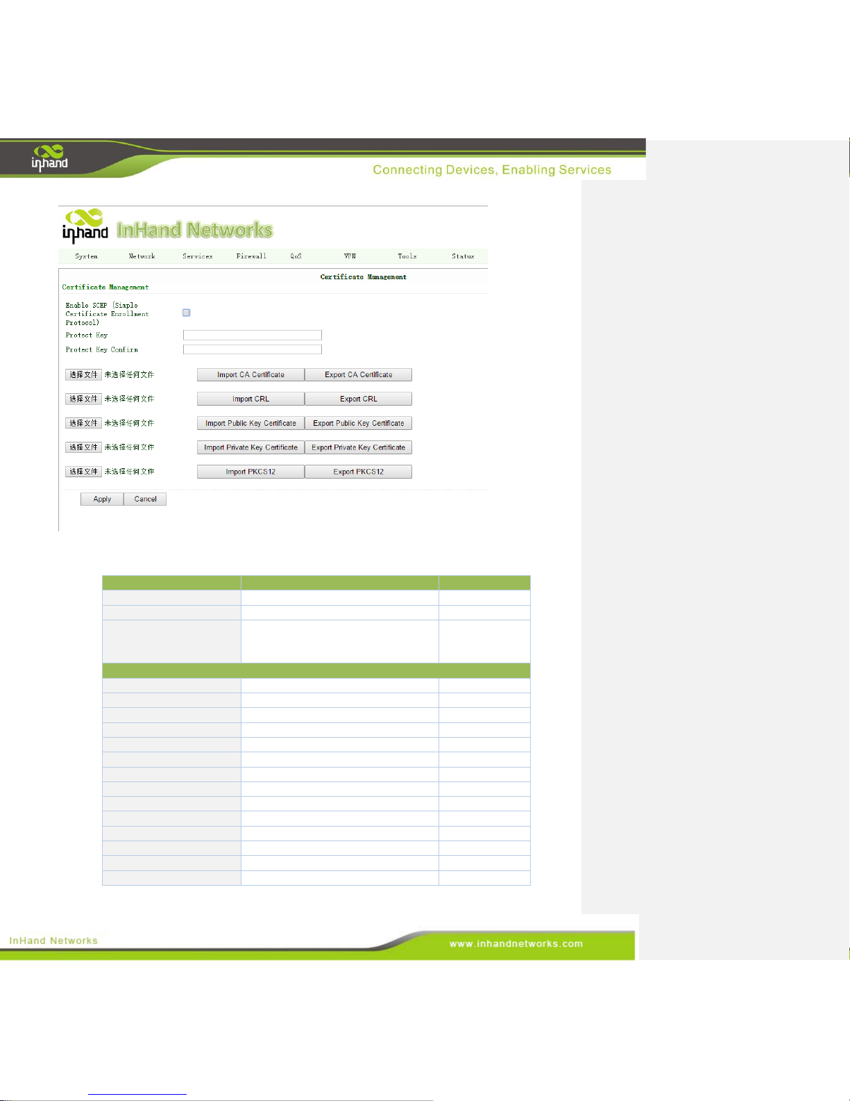
80 / 92
Page description is shown below:
Parameters
Description
Default
Protect Key
Set protect key
N/A
Protect Key Confirm
Confirm protect key
N/A
Enable SCEP (Simple
Certificate Enrollment
Protocol)
Click to enable
Disable
SCEP Parameters
Force to re-enroll
Click to enable
Disable
Server URL
Set sever URL
N/A
Common Name
Set common name
N/A
FQDN
Set FQDN
N/A
Unit 1
Set unit 1
N/A
Unit 2
Set unit 2
N/A
Domain
Set domain
N/A
Serial Number
Set serial number
N/A
Challenge
Set challenge
N/A
Challenge Confirm
Challenge confirm
N/A
Unstructured address
Set unstructured address
N/A
RSA Key Length
Set RSA key length
1024
Poll Interval
Poll interval
60 seconds
Poll Timeout
Poll timeout
3600 seconds
Page 81
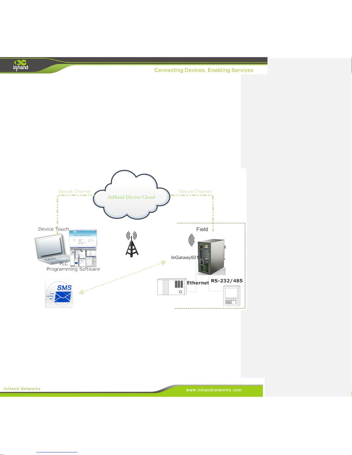
81 / 92
4. Applications
With the development of industry and the popularity of automated equipment, equipment
manufacturers are now facing increasingly large amount of maintenance work and other problems like:
How to prevent unexpected downtime of automation equipment? How to monitor the operating status
of the device? How to reduce engineer's travel for maintenance? InHand Networks, combining market
and user’s needs, provides complete remote maintenance solutions for automation equipment. As a
gateway, IG601 build a secure channel between remote equipment, device cloud platform and
maintenance engineers. Please see the network diagram below:
Page 82

82 / 92
Appendix I FAQ
1, InGateway is powered on, but can`t access Internet through it?
Please check:
Whether the InGateway is inserted with a SIM card.
Whether the SIM card is enabled with data service, whether the service of the SIM card is
suspended because of an overdue charge.
Whether the dialup parameters, e.g. APN, dialup number, username and password are correctly
configured.
Whether the IP Address of your computer is the same subnet with InGateway and the gateway
address is InGateway LAN address.
2, InGateway is powered on, have a ping to detect InGateway from your PC and find packet loss?
Please check if the network crossover cable is in good condition.
3, Forget the setting after revising IP address and can`t configure InGateway?
Method 1: connect InGateway with serial cable, configure it through console port.
Method 2: Locate the RESET button on the device; Turn on the device’s power; within 10 seconds,
press and hold RESET button; When ERR LED is on, release the RESET button; Within a few seconds,
ERR LED should go off; then press and hold the RESET button again; When the ERR LED blinks,
release the RESET button; If the ERR LED goes off, that means InGateway601 is now restoring to
factory default settings; You can log in using the 192.168.2.1.
4, After InGateway is powered on, it frequently auto restarts. Why does this happen?
Please check:
Whether the module works normally.
Whether the InGateway is inserted with a SIM card.
Whether the SIM card is enabled with data service, whether the service of the SIM card is
suspended because of an overdue charge.
Whether the dialup parameters, e.g. APN, dialup number, username and password are correctly
configured.
Whether the signal is normal.
Whether the power supply voltage is normal.
5, Why does upgrading the firmware of my InGateway always fail?
Page 83

83 / 92
Please check:
When upgrading locally, check if the local PC and InGateway are in the same network segment.
When upgrading remotely, please first make sure the InGateway can access Internet.
6, After InGateway establishes VPN with the VPN server, your PC under InGateway can connect
to the server, but the center can`t connect to your PC under InGateway?
Please make sure the firewall of your computer is disabled.
7, After InGateway establishes VPN with the VPN server, Your PC can`t connect to the server?
Please make sure “Shared Connection” on “Network=>WAN” or “Network=>Dialup” is enabled in the
configuration of InGateway.
8, InGateway is powered on, but the Power LED is not on?
Check if the protective tube is burn out.
Check the power supply voltage range and if the positive and negative electrodes are correctly
connected.
9, InGateway is powered on, but the Network LED is not on when connected to PC?
When the PC and InGateway are connected with a network cable, please check whether a network
crossover cable is used.
Check if the network cable is in good condition.
Please set the network card of the PC to 10/100M and full duplex.
10, InGateway is powered on, when connected with PC, the Network LED is normal but can`t
have a ping detection to the InGateway?
Check if the IP Address of the PC and InGateway are in the same subnet and the gateway address is
InGateway LAN address.
11, InGateway is powered on, but can`t configure through the web interface?
Whether the IP Address of your computer is the same subnet with InGateway and the gateway
address is InGateway LAN address.
Check the firewall settings of the PC used to configure InGateway, whether this function is shielded
by the firewall.
12, The InGateway dialup always fails, I can`t find out why?
Please restore InGateway to factory default settings and configure the parameters again.
13, How to restore InGateway to factory default settings?
1. Locate the RESET button on the device;
2. Turn on the device’s power; within 10 seconds, press and hold RESET button;
Page 84

84 / 92
3. When ERR LED is on, release the RESET button;
4. Within a few seconds, ERR LED should go off; then press and hold the RESET button again;
5. When the ERR LED blinks, release the RESET button; If the ERR LED goes off, that means
InGateway601 is now restoring to factory default settings;
6. You can log in using the 192.168.2.1.
Appendix II Command Lines
1 Help Command
Help command can be obtained after entering help or “?” into console, “?” can be entered at any time
during the process of command input to obtain the current command or help from command parameters,
and command or parameters can be automatically complemented in case of only command or
command parameter.
1.1 Help command
[Command] help [<cmd>]
[Function] get help from command
[View] all views
[Parameter]<cmd> command name
[Example]
enter: help
Get the list of all current available command.
enter: help show
Display all the parameters of show command and using instructions thereof.
2 View Switchover Command
2.1 enable
[Command] enable [15 [<password>]]
[Function] Switchover to privileged user level.
[View] Ordinary user view.
[Parameter]15 User right limit level, only supports right limit 15 (super users) at
current.
<password> Password corresponded to privileged user limit level, hint of password
inputting will be given in case of no entering.
[Example] Enterenable adm in ordinary user view
Switchover to super users and the password 123456
2.2 disable
[Command] disable
[Function] Exit the privileged user level.
[View] Super user view, configure view
[Parameter] No
[Example] Enter disable in super user view
Return to ordinary user view.
2.3 end and !
[Command]end or !
[Function] Exit the current view and return to the last view.
[View] Configure view.
[Parameter] No
Page 85

85 / 92
[Example] Enter end in configured view
Return to super user view.
2.4 exit
[Command]exit
[Function] Exit the current view and return to the last view (exit console in case that it is ordinary user)
[View] all views
[Parameter] No
[Example]
enter exit in configured view
Return to super user view.
enter exit in ordinary user view
Exit console.
3 Check system state command
3.1 show version
[Command] show version
[Function] Display the type and version of software of the gateway
[View] all views
[Parameter] No
[Example] enter: show version
Display the following information:
Type : display the current factory type of IG601
Serial number : display the current factory serial number of IG601
Description : www.inhandnetworks.com
Current version : display the current version of IG601
Current version of Bootloader: display the current version of IG601
3.2 show system
[Command] show system
[Function] display the system information of IG601
[View] all views
[Parameter] No
[Example] enter: show system
Display the following information
Example: 00:00:38 up 0 min, load average: 0.00, 0.00, 0.00
3.3 show clock
[Command] show clock
[Function] display the system time of IG601
[View] all views
[Parameter] No
[Example] enter: show clock
Display the following information:
For example Sat Jan 1 00:01:28 UTC 2000
3.4 show modem
[Command] show modem
[Function] Display the MODEM state of IG601
[View] all views
[Parameter] No
[Example] Enter: show modem
Display the following information:
Page 86

86 / 92
Modem type
state
manufacturer
product name
signal level
register state
IMSI number
Internet state
3.5 show log
[Command] show log [lines <n>]
[Function] display the system log of IG601 and display the latest 100 logs in default.
[View] all views
[Parameter]lines <n> limits the log numbers displayed, wherein, n indicates the latest n logs in case
that it is positive integer and indicates the earliest n logs in case that it is negative integer and
indicates all the logs in case that it is 0.
[Example] enter: show log
Display the latest 100 log records.
3.6 show users
[Command] show users
[Function] display the user list of IG601.
[View] all views
[Parameter] No
[Example] input: show users
Displayed user list of system is as follows:
User:
------------------------------------------------* adm
-----Wherein, user marked with * is super user.
3.7 show startup-config
[Command]show startup-config
[Function] Display the startup-config of IG601
[View] super user view and configuration view
[Parameter] No
[Example] enter: show startup-config
Display the starting configuration of system.
3.8 show running-config
[Command] show running-config
[Function] display the operational configuration of IG601
[View] super user view, configuration view
[Parameter] No
[Example] Enter: show running-config
Display the operational configuration of system.
4 Check the Command of Internet State
4.1 show interface
[Command] show interface
[Function] Display the information of port state of IG601
Page 87

87 / 92
[View] all views
[Parameter] No
[Example]enter: show interface
Display the state of all ports.
4.2show ip
[Command] Show ip
[Function] Display the IP status of IG601
[View] all views
[Parameter] No
[Example] enter: Show ip
Display system ip status
4.3 show route
[Command] Show route
[Function] Display the routing list of IG601
[View] all views
[Parameter] No
[Example] enter: Show route
Display system routing list
4.4 show arp
[Command] show arp
[Function] Display the ARP list of IG601
[View] all views
[Parameter] No
[Example] enter: show arp
Display the ARP list of system
5 Internet Testing Command
IG601 has provided ping, telnet and traceroute for internet testing.
5.1 ping
[Command]ping <hostname> [count <n>] [size <n>] [source <ip>]
[Function] apply ICMP testing for appointed mainframe.
[View] all views
[Parameter]<hostname> tests the address or domain name of mainframe.
count <n> testing times
size <n> tests the size of data package (byte)
source <ip> IP address of appointed testing
[Example] enter: ping www.g.cn
Test www.g.cn and display the testing results
5.2 telnet
[Command] telnet <hostname> [<port>] [source <ip>]
[Function] telnet logs in the appointed mainframe
[View] all views
[Parameter]<hostname> in need of the address or domain name of mainframe logged in.
<port>telnet port
source <ip> appoints the IP address of telnet logged in.
[Example] enter: telnet 192.168.2.2
telnet logs in 192.168.2.2
Page 88

88 / 92
5.3 traceroute
[Command] traceroute <hostname> [maxhops <n>] [timeout <n>]
[Function] test the acting routing of appointed mainframe.
[View] all views
[Parameter]<hostname> tests the address or domain name of mainframe
maxhops <n> tests the maximum routing jumps
timeout <n> timeout of each jumping testing (sec)
[Example] enter: traceroute www.g.cn
Apply the routing of www.g.cn and display the testing results.
6 Configuration Command
In super user view, IG601 can use configure command to switch it over configure view for
management. Some setting command can support no and default, wherein, no indicates the setting
of cancelling some parameter and default indicates the recovery of default setting of some
parameter.
6.1 configure
[Command] configure terminal
[Function] switchover to configuration view and input the configuration at the terminal end.
[View] super user view
[Parameter] No
[Example] enter configure terminal in super user view
Switchover to configuration view.
6.2 hostname
[Command] hostname [<hostname>]
default hostname
[Function] Display or set the mainframe name of IG601
[View] Configuration view
[Parameter]<hostname> new mainframe name
[Example]
enter hostname in configuration view
Display the hostname name of IG601.
enter hostname MyGateway in configuration view
Set the IG601 hostname to MyGateway.
enter default hostname in configuration view
Recover the IG601 hostname to the factory setting.
6.3 clock timezone
[Command] clock timezone <timezone><n>
default clock timezone
[Function] set the time zone information of IG601.
[View] Configuration view
[Parameter]<timezone> timezone name, 3 capitalized English letters
<n> time zone deviation value, -12~+12
[Example]
enter clock timezone CST -8 in configuration view
The time zone of IG601is east eighth area and the name is CST (China’s standard time).
enter default clock timezone in configuration view
The time zone of IG601 is recovered to the factory setting.
6.4 clock set
Page 89

89 / 92
[Command]clock set <YEAR/MONTH/DAY> [<HH:MM:SS>]
[Function] set the date and time of IG601.
[View] Configuration view
[Parameter]<YEAR/MONTH/DAY> date, format: Y-M-D
<HH:MM:SS > time, format: H-M-S
[Example] enter clock set 2009-10-5 10:01:02 in configuration view
The time of router set is 10:01:02 of Oct. 5th, 2009 morning.
6.5 ntp server
[Command]ntp server <hostname>
no ntp server
default ntp server
[Function] set the customer end of internet time server
[View] configuration view
[Parameter]<hostname> address or domain name of mainframe of time server
[Example] enter sntp-client server pool.ntp.org in configuration view
Set the address of internet time server pool.ntp.org.
6.6 config export
[Command]config export
[Function] export config
[View] Configuration view
[Parameter] N/A
[Example]
enter config export in configuration view
The current config.is exported.
6.7 config import
[Command]config import
[Function] import config
[View] Configuration view
[Parameter] N/A
[Example]
enter config import in configuration view
The config.is imported
7 System Management Command
7.1 reboot
[Command] reboot
[Function] System restarts.
[View] super user view, configuration view
[Parameter] No
[Example] enter reboot in super user view
System restarts.
7.2 enable username
[Command] enable password [<name>]
[Function] modify the username of super user.
[View] configuration view
[Parameter]<name> new super user username
[Example] enter enable username admin in configuration view
The username of super user is changed to admin.
Page 90

90 / 92
7.3 enable password
[Command] enable password [<password>]
[Function] modify the password of super user.
[View] configuration view
[Parameter]<password> new super user password
[Example] enter enable password in configuration view
Enter password according to the reminder.
7.4 username
[Command] username <name> [password [<password>]]
no username <name>
default username
[Function] set user name, password
[View] configuration view
[Parameter] No
[Example]
enter username abc password 123 in configuration view
Add an ordinary user, the name is abc and the password is 123.
enter no username abc in configuration view
Delete the ordinary user with the name of abc.
enter default username in configuration view.
Delete all the ordinary users.
Page 91

91 / 92
Appendix III Description of LED
Operation Status:
STATUS
WARN
ERROR
Description
Green
Yellow
Red
On
On
Off
Power on
Blink
On
Off
Power on succeed
Blink
Blink
Off
Dialing
Blink
Off
Off
Dialing succeed
Blink
Blink
Blink
Upgrading
Blink
On
Blink
Reset Succeed
Signal Status:
Green LED 1
Green LED 2
Green LED 3
Description
Off
Off
Off
No signal detected
On
Off
Off
Signal strength 1-9(signal
weak, please check antenna)
On
On
Off
Signal strength 10-19(signal
medium)
On
On
On
Signal strength 20-31(signal
strong)
Ethernet Port Status:
Yellow LED
Green LED
Description
On
On
ETH 100M, normal, no data transmission
Blinking
On
ETH 100M, normal, with data transmission
On
Off
ETH 10M, normal, no data transmission
Blinking
Off
ETH 10M, normal, with data transmission
POWER Status:
POWER Red LED
Description
On
Power connected
Off
No power connection
MODEM Status:
Page 92
92 / 92
MODEM Green LED
Description
On
Modem in normal status
Off
Modem abnormal
 Loading...