

Ingrasys iSC-NVR2316-T, iSC-NVR2532-T, iSC-NVR2532-U, iSC-NVR2532-R, iSC-NVR2532-A User Manual
...
SmartVIEW NVRs
User Manual
Copyright © Ingrasys Technology Inc. All rights reserved.
iSC-NVR2316-T / iSC-NVR2532-T
iSC-NVR2532-U / iSC-NVR2532-R
iSC-NVR2532-A / iSC-NVR2532-D
Version 1.5

About This Document
This manual is intended for administrators and users of iSC-NVR2532-U/R/A/D/T and
iSC-NVR2316-T. It covers configuration of storage and SmartVIEW configuration, as well as
instructions for using and managing SmartVIEW NVRs on your mobile devices. Later versions
of this document will be posted on the official website, as required.
The use of video surveillance devices can be prohibited by laws that vary from country to
country. It is the user’s responsibility to ensure that the operation of such devices is legal
before installing this unit for surveillance purposes.
Version history
Version
Description
Date
1.5
First release
2014-06-10

Legal Notices
Ingrasys Technology Inc. reserves the right to modify product specifications without
notification. The contents of this document may be modified without notification.
The trademark of SmartVIEW is the property of Ingrasys Technology Inc. All other trademarks,
registered trademarks, and product names mentioned in this document are the properties of
their respective owners. In addition, the “TM” symbols are omitted in this document.
The iPhone and iPad trademarks are the property of Apple Inc. All other trademarks,
registered trademarks, and product names mentioned in this document are the properties of
their respective owners. In addition, the “TM” symbols are omitted in this document.
Liability
Every care has been taken in the preparation of this manual. Ingrasys cannot be held
responsible for any technical or typographical errors and reserves the right to make changes
to the product and manuals without prior notice. Ingrasys makes no warranty of any kind
with regard to the material contained within this document, including, but not limited to, the
implied warranties of merchantability and fitness for a particular purpose. Ingrasys shall not
be liable or responsible for incidental or consequential damages in connection with the
furnishing, performance or use of this material.
Support
Should you require any technical assistance, please contact your reseller or SI. If your
questions cannot be answered immediately, please forward your queries through the
appropriate channels to ensure a rapid response.

Introduction
SmartVIEW is a series of user-friendly Windows-based NVRs which can manage up to 32
channels with just one server. It provides powerful local display functionality with up to 32
channels live view and 16 channel playbacks. The whole series of SmartVIEW NVR provides
completed hardware solutions for user to choose what’s the best for their application is,
include both rack mount and tower desktop types.
For remote monitoring, user can log-in NVR built-in remote web client interface or iOS
mobile APP Eye2GO, to access to their monitoring system anytime and anywhere.
Furthermore, with our “Internet Service” and “UPnP” functions, user can easily access NVR
data from internet. For Eey2GO, user can monitor multiple NVRs on Eye2GO APP at a time, or
monitor single NVR from web client.

Table of Contents
1 System Overview ............................................................................. 6
1.1 How to start? ............................................................................................................. 6
1.2 Hardware interface .................................................................................................... 7
2 System Setting ............................................................................... 12
2.1 SysGuard .................................................................................................................. 12
2.2 RAID Setting ............................................................................................................. 15
2.3 Add Storage ............................................................................................................. 19
2.4 Change System Language ........................................................................................ 21
3 SmartVIEW initialization ................................................................ 23
3.1 Installation Wizard ................................................................................................... 23
3.2 Exit the system ......................................................................................................... 28
3.3 Log Off and Switch Login User ................................................................................. 29
4 Live view ....................................................................................... 30
4.1 The Live view page ................................................................................................... 30
4.2 About the SmartVIEW System Version .................................................................... 36
4.3 System Information ................................................................................................. 37
4.4 Two-way audio chat and broadcast control............................................................. 38
4.5 Digital PTZ ................................................................................................................ 39
4.6 Snapshot Browsing .................................................................................................. 40
4.7 Speed Dome Camera Control .................................................................................. 41
4.8 Screen Layout .......................................................................................................... 46
4.9 Event Display............................................................................................................ 47
5 System Settings ............................................................................. 49
5.1 System Configurations ............................................................................................. 49

5.2 Storage Settings ....................................................................................................... 51
5.3 User Account Management ..................................................................................... 53
5.4 Hardware Monitoring .............................................................................................. 59
5.5 IP Camera Management .......................................................................................... 60
5.6 Group Settings ......................................................................................................... 70
5.7 Sequence Settings ................................................................................................... 72
5.8 SMS / Email Settings / FTP Settings ......................................................................... 75
5.9 DO (Digital Output) Settings .................................................................................... 77
5.10 Sensor Settings ........................................................................................................ 79
5.11 Event Action Settings ............................................................................................... 81
6 Playback & Log search ................................................................... 84
6.1 Playback ................................................................................................................... 84
6.2 Event Log Query ....................................................................................................... 99
7 Network Service Configuration .................................................... 101
8 Internet Service Configuration ..................................................... 104
9 Remote web client ...................................................................... 105
9.1 Log-in and Live View page ..................................................................................... 105
9.2 Remote event search ............................................................................................. 108
9.3 Remote video playback.......................................................................................... 109
10 Backup Player .............................................................................. 111
11 Eye2GO ....................................................................................... 113
12 . Abbreviation and definition ....................................................... 113

6
1 System Overview
1.1 How to start?
Following steps are for bringing on this system from storage setting to starting recording and
live viewing. Details will be described in following contents.
Hardware preinstall & power on
RAID setting
(for iSC-NVR2532-R/A/D)
Windows partition setting
Enable SysGuard
NVR quick setting by Installation wizard
Enjoy your surveillance system
7
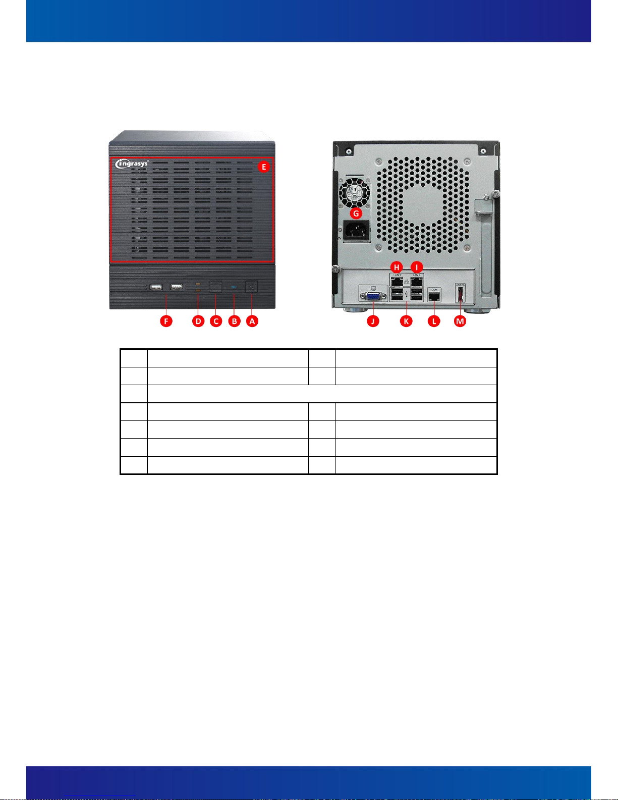
1.2 Hardware interface
(1) NVR2316-T
A
Power switch
B
Power LED
C
Reset button
D
System read/write LED
E
Front cover for 4 x 3.5” lockable HDD trays
F
2 x USB 2.0
G
Power socket
H
LAN
I
LAN
J
VGA
K
4 x USB 2.0
L
COM
M
E-SATA

8
(2) NVR2532-T
A
Power switch
B
Power LED
C
Reset button
D
System read/write LED
E
Front cover for 4 x 3.5” lockable HDD trays
F
2 x USB 2.0
G
Power socket
H
Audio Jack
I
COM1
J
COM2
K
VGA
L
DVI-D
M
HDMI
N
LAN
O
LAN
P
4 x USB 2.0

9
(3) NVR2532-U
A
Power switch
B
Alarm mute button
C
Fan failed LED
D
Power LED
E
4 x 3.5” HDD tray
F
Power socket
G
Audio Jack
H
COM1
I
COM2
J
VGA
K
DVI-D
L
HDMI
M
LAN
N
LAN
O
4 x USB 2.0

10
(4) NVR2532-R / NVR2532-A (Redundant PSU)
A
Power switch
B
System reset button
C
Alarm mute button
D
System R/W LED
E
Power LED
F
System Alarm LED
G
LAN1 LED
H
LAN2 LED
I
2 x USB 2.0
J
16 x 3.5” HDD tray
K
Power socket
L
Audio Jack
M
COM1
N
COM2
O
VGA
P
DVI-D
Q
HDMI
R
LAN
S
LAN
T
4 x USB 2.0
NVR2532-R
NVR2532-A (Redundant PSU)

11
(5) NVR2532-D
A
Power button
B
System reset button
C
Alarm mute button
D
Power LED
E
System Alarm LED
F
LAN1 LED
G
LAN2 LED
H
2 x USB 2.0
I
24 x 3.5” HDD tray
J
Power socket
K
Audio Jack
L
COM1
M
COM2
N
VGA
O
DVI-D
P
HDMI
Q
LAN
R
LAN
S
4 x USB 2.0

12
2 System Setting
2.1 SysGuard
To prevent from any exception and keep high performance for the SmartVIEW NVR, the
operation system is built with Microsoft Window Embedded 7 and the system drive (Drive C)
is protected with FBWF (File Base Write Filter). If you want to change any settings of
Windows operating system (i.e. storage, network IP address, system time zone, system
date/time, computer name … etc.), you MUST follow the steps to apply changes.
Please do the 4 steps below before using SmartVIEW NVR.
Notice : For the system safety, you have to enable the SysGuard for running SmartVIEW
NVR after changing settings on Windows operation system.
○1 Choose not to enable SysGuard
when warning message pops up.
○4 System auto reboot
○2 Change settings
○3 Enable SysGuard
13
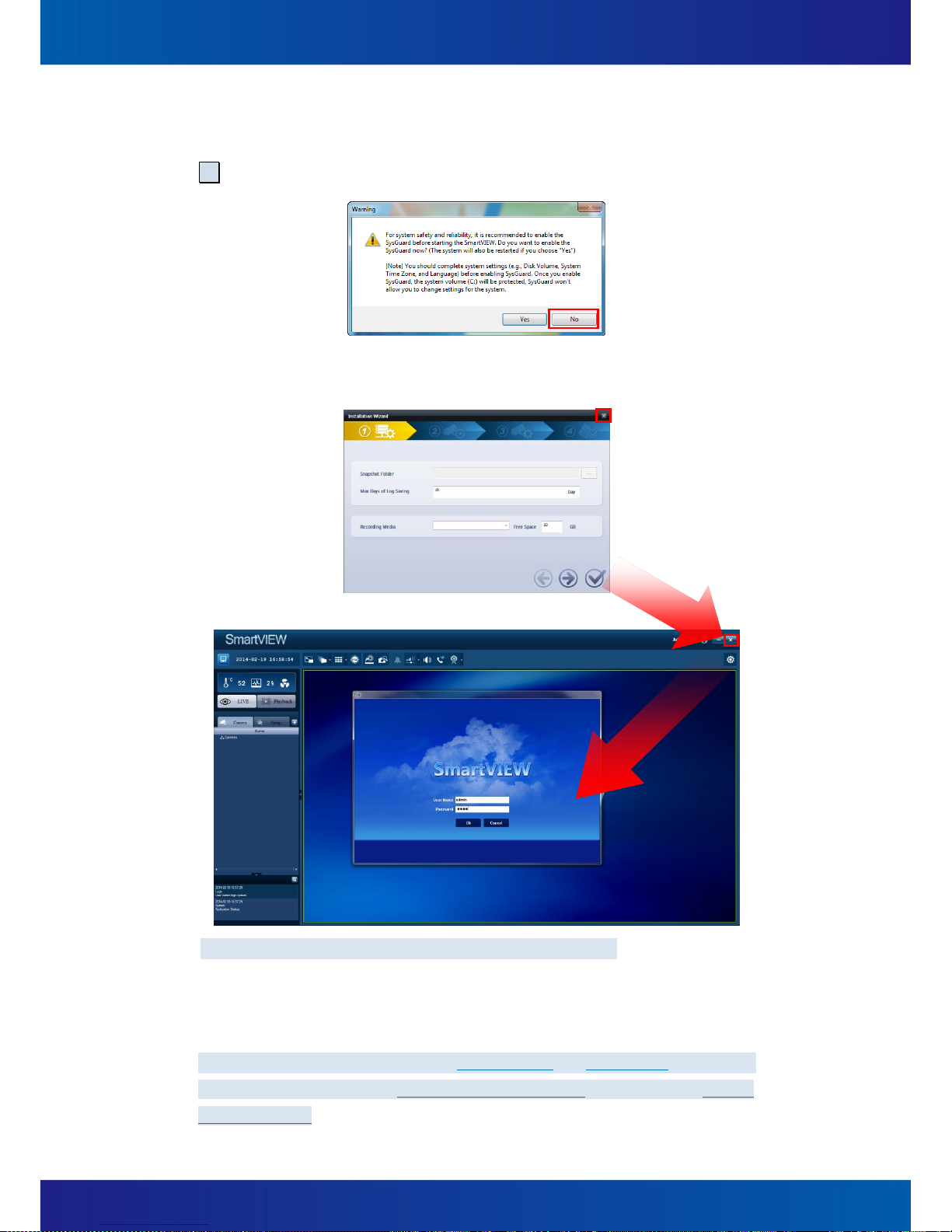
(1) You should disable the SysGuard before changing the system settings.
After system start up, system will pop out a warning message automatically, please click
No to disable the SysGuard.
(2) Close Install action Wizard and SmartVIEW for changing Windows operation system
settings.
Notice:Default user name is admin, default password is 1234
You can change the system settings after disabling SysGuard. In this session, all the
changes of the system settings would be applied and the system is not under protection
until the SysGuard is enabled.
Notice:The most important setting is to create RAID and format disks, SmartVIEW
Installation Wizard will apply 1st available drive letter (e:) automatically as default
Recording Media

14
(3) Double click on the shortcut of system desktop and click Yes to enable the
SysGuard. System will be restarted automatically.
(4) If your SmartVIEW is already running and SysGuard is enabled, you may open the
SysGuard program and select Disable the SysGuard function and click OK. Then, click
Yes . The system will be restarted to disable the SysGuard. After system reboot, please
refer to above steps to change settings.
15
2.2 RAID Setting
Notice : For NVR2532-R / NVR2532-A / NVR2532-D Only.
If you are using NVR2316-T, NVR2316-K, or NVR2532-T, please Skip to Chapter 2.3 directly.
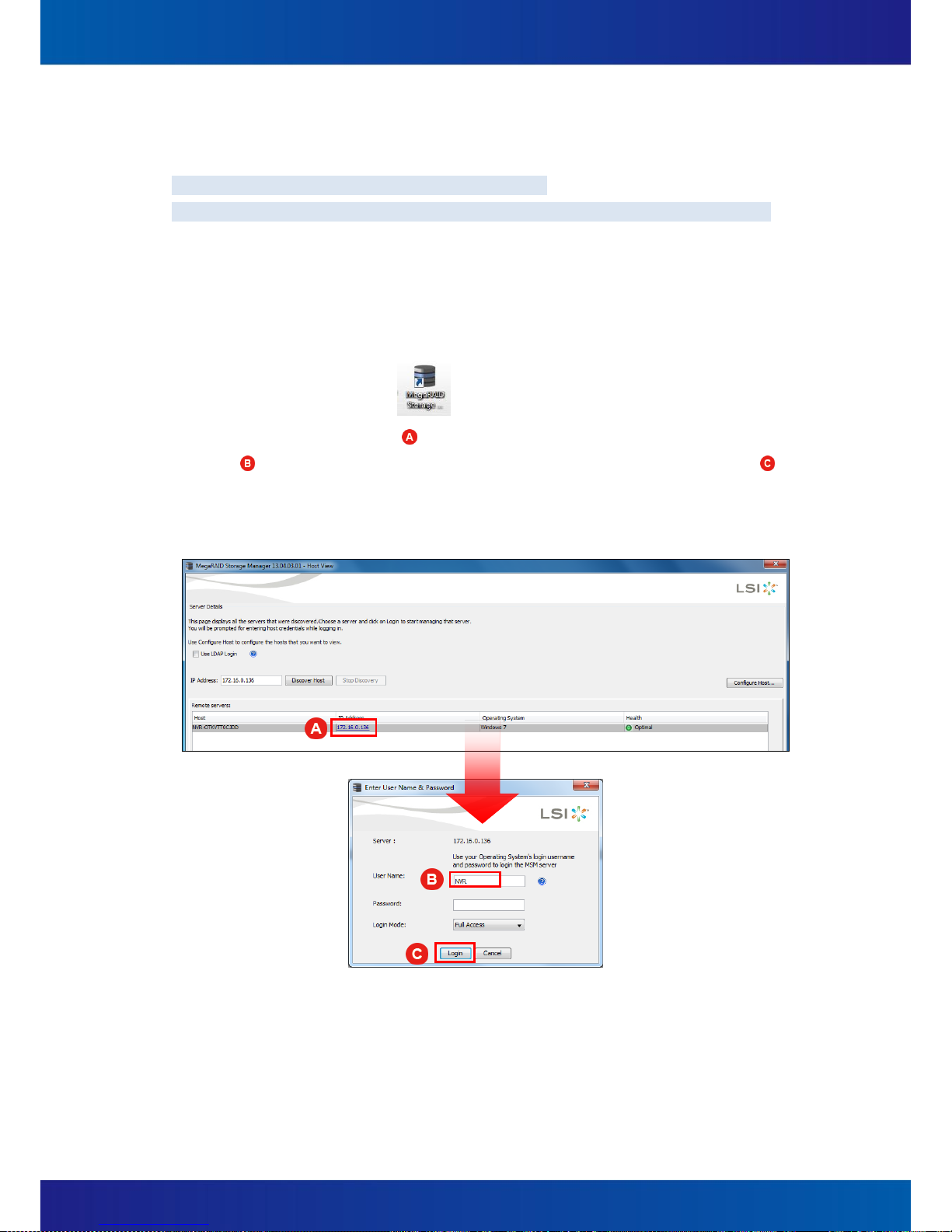
(1) Login MegaRAID Storage Manager
A. Insert all hard drives to the trays.
B. Power on the system.
C. Please disable the SysGuard (Refer to Chapter 2.1) before changing the RAID
settings.
D. Double click on the icon on the Windows desktop to open the MegaRAID
Storage Manager.
E. Click on IP Address link ( ) under Remote servers list to type User Name “NVR”
( ) and password (There’s no password in the default setting) then click Login ( )
button to login MegaRAID Storage Manager.

16
(2) RAID configuration
You will enter the main console of MegaRAID Storage Manager.
A. Select to Physical tab and make sure every hard disks you installed in your
SmartVIEW NVR’s front slots are all “Unconfigured Good” (like )
B. Right click on LSI MegaRAID SAS 9260-4i ( ) and choose Create Virtual Drive.
C. Create Virtual Drive – Choose mode will pop up, please select on Simple and click
Next button.

17
D. Create Drive Group – Drive group and Virtual drive settings will pop up, please
select RAID 5 ( ), then click Next ( ) button to create RAID.
E. Create Virtual Drive - Summary window will pop up to confirm all settings are
correct, and then click Finish and OK to complete settings.

18
F. Please make sure all HDD you configured are online ( ).
G. These hard drives will be regarded as one single disk in Windows7 operation
system.
Now you may go to initialize the disk and create new volumes through right click
mouse at WindowsComputer and select on ManageDisk Management.
Please be aware of the recommended maximum volume size is less than 2TB for
the best performance of database.
(3) Enable SysGuard
Please execute SmartVIEW and enable the SysGuard. The system will be under
protection after system is restarted.

19
2.3 Add Storage
SmartVIEW NVR is capable to install up to 24 hard drives as recording storages. To keep the
system working normally, you should operate steps as the following for adding recording
storages:
Notice:If you are using NVR2532-R/A/D and your RAID setting has been just done, please
jump to step (5) directly.
(1) Insert all hard drives to the trays.
(2) Power on the system.
(3) Please disable the SysGuard (Refer to Chapter 2.1) before add storage of SmartVIEW.
(4) For storage volume setting in Windows, you may go to initialize the disks and create
new volumes through right click mouse at Windows Computer and select on
Manage Disk Management. Please be aware of the recommended maximum
volume size is less than 2TB for the best performance of database.
(5) After disk volumes were created properly, system will pop-up window as following
picture. Please close the AutoPlay window.

20
(6) Double click on the icon on the Windows desktop to enable SysGuard, after
reboot, SmartVIEW will be started automatically, you may go to Chapter 7. About
“Quick Setting” to add camera directly or click Setup , expand System menu and
select Storage to add more storages if you already added cameras and have many drive
letters.
Notice: More details are described in the Chapter 5.2 of the Users’ Manual.

21
2.4 Change System Language
If you want to change the system language, please follow the steps to change the operating
system display language and system locale
(1) Please disable the SysGuard (Refer to Chapter 2.1) before changing the system settings.
(2) The system will be restarted to disable the SysGuard.
(3) Open the Control Panel Click Region and Language .
(4) Click Keyboards and Languages ( )and select a proper display language ( ).

22
(5) Click Administrative.
(6) Click the button, Change system locale…
(7) Select a proper system locale and click OK .
Notice:STOP!! A Change System Local dialog box as the following would be shown.
Please DO NOT click any button on this dialog box. Just ignore it.
(8) Double click on the shortcut of system desktop, then click Yes to enable the
SysGuard, system will be restarted automatically.
(9) The system change (language setting) would be applied after the system reboot.

23
3 SmartVIEW Initialization
3.1 Installation Wizard
Once the SmartVIEW software has been lunched first time after completing Windows
system settings and enabling SysGuard, the Installation Wizard will be also automatically
started. This wizard will help users to easily configure the system setting values (ex.
Snapshot Folder, Max Record Days, Recording Media, and the Free Space of the recording
media) and Cameras Discovery.
Users are able to set: (Figure 3-1~Figure 3-5)
(1) System Setting (Figure 3-1)
Snapshot Folder:To assign a folder to store snapshot pictures.
Max Record Days:To specify the maximum days for reserving event logs.
Recording Media:To assign a storage partition for video / audio recording data.
Free Space:To specified the reserved space of this partition that assigned for storing
recording data
and will be disabled (gray) until any available recording storage is installed.
Figure 3-1

24
OK:To start using SmartVIEW immediately and leave the wizard.
NEXT:To enter the next step of the wizard.
PREV:To back the previous step of the wizard.
Exit:To exit the wizard without saving.
(2) Cameras Discovery
(3) Users are able to complete most basic and important settings on adding a camera. By
Cameras Discovery, users can find all cameras in local network and then complete basic
setting easily. (Figure 3-2)
Discovery:To start the cameras discovery procedure.
Figure 3-2

25
Recording (Figure 3-3):To turn on / off the video recording function.
(Users are needed to prepare the storage of recording for each camera in the system
configuration.)
Add (Figure 3-3):To specify whether the camera to be managed or not.
Figure 3-3
Note: User can choose to finish the setting and enter SmartVIEW main console after
this step. If user wants to have detail setting, please go to next step.
26
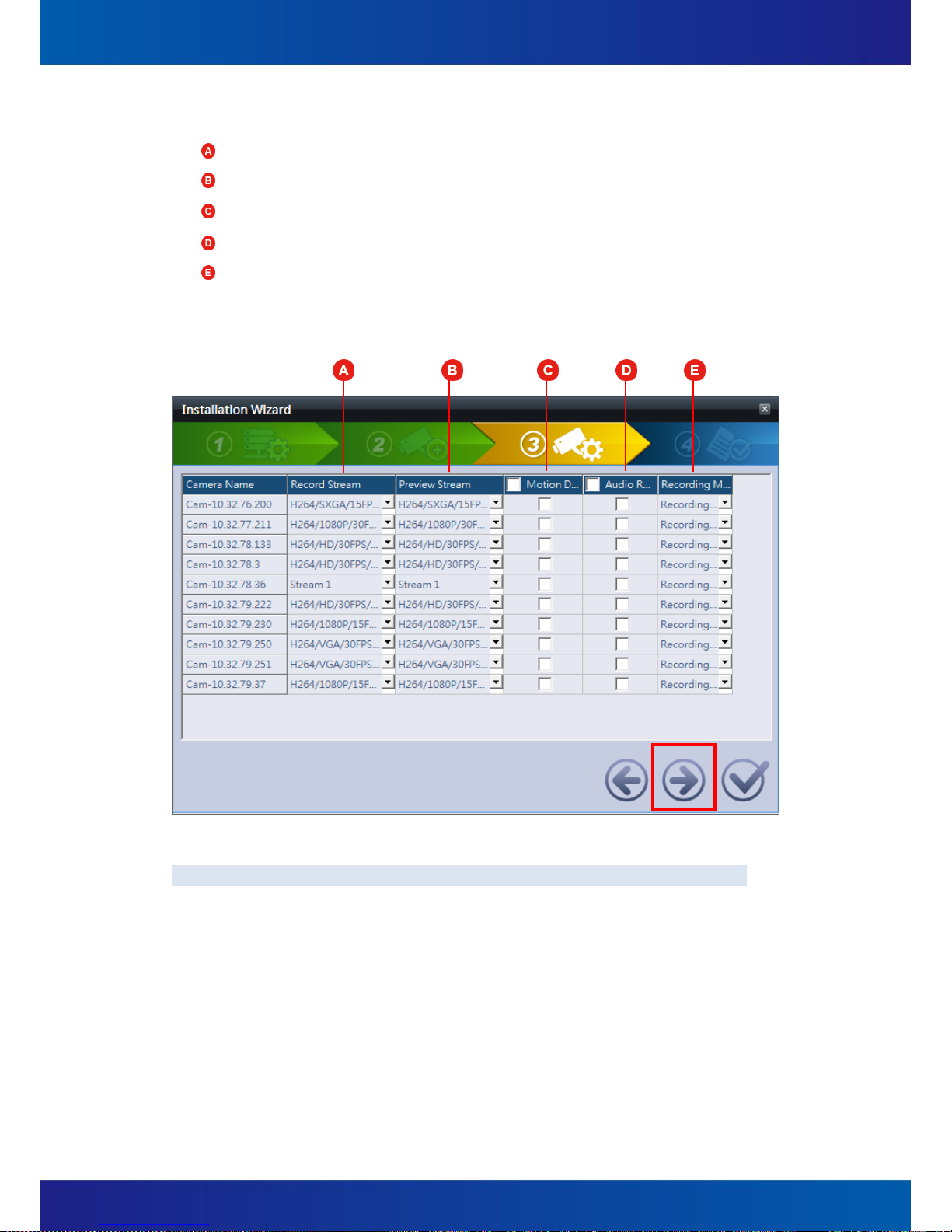
(4) Cameras Setup (Figure 3-4)
Record Stream:To assign a stream for recording.
Preview Stream:To assign a stream for previewing.
Motion Detecting:To turn on / off the motion detecting function.
Audio Recording:To turn on / off the audio recording function.
Recording Mode:To specify the recording mode. (Full-time Recording / Event-driven
Recording)
Figure 3-4
Notice:All of these settings are also to be modified later in the System Configuration.

27
(5) Confirmation Step (Figure 3-5)
Figure 3-5

28
3.2 Exit the system
If user wants to exit from this program, on the main page of SmartVIEW software, click on
the icon Exit AP (Figure 3-6a, ), then a dialog box which is titled Exit will be pop-up
(Figure 3-6b) and you will need an authorized account to exit system. In the Exit dialog box,
you may click the button Cancel to give up exiting system.
Figure 3-6a
Figure 3-6b

29
3.3 Log Off and Switch Login User
In the main page of SmartVIEW software, click on the icon Switch User (Figure 3-6a, ),
a dialog box which is titled Switch User will be pop-up (Figure 3-7) and you will need an
authorized account to exit system. In the Switch User dialog box, you may click the button
Cancel to give up log off system.
Figure 3-7

30
4 Live view
4.1 The Live view page
Users are able to monitor the real-time videos on the Live View page; users can also query
the system event log, monitor the system Hardware status, or control PTZ (pan/tilt/zoom) of
the speed dome cameras.
Figure 4-1
System information
Main content
System status & Source of content
Cross-channel functions

31
Figure 4-1a
(1) To display live video, just drag channels or a whole group from the channel tree (Figure
4-1a, ) and drop into any video display window.
(2) To drag and drop the videos, users are able to re-arrange the channel display order.
(3) Double-clicking any video will enlarge this channel into a single-cannel layout.
Double-clicking the video again will let the video restore to the original layout. This
feature is both provided in the Live View page and Playback page.
(4) Click on the icon will make the video display become full-screen. Click “ESC” on
user’s keyboard will make it back to the original display status. (Figure 4-1a, )
(5) Real-time video snapshot:Move the mouse cursor to the upper left corner of any
video window, the mouse cursor would become a “camera” icon and users are able to
take snapshots by clicking the “camera” icon (Figure 4-1b, ). Users are also able to
open the “Snapshot Viewer” to browse the snapshots. To open the Snapshot Viewer,
users may move the mouse cursor in any video window and click the right button of the
mouse, and then select the “Snapshot” item (Figure 4-1c).
Note: User can also refer to Chapter 4.6 for more detail of snapshot functionality.

32
Figure 4-1b
(6) Click the right button of the mouse on a channel’s video window (Figure 4-1c), users are
able to do other operations like:
Figure 4-1c
Reconnect:Manually reconnect this channel if there’s trouble of video displaying.
Record Stream:Display for record stream of this channel on live view
Preview Stream:Display for preview stream of this channel on live view
Manual Recording:Users can manually start/stop recording despite of the current
recording mode of that channel and search in the playback page. About the duration
of an event, it will be defined as the time span from the starting to the stopping of
the manual recording.

33
Snapshot:Snapshots browsing for all channels and all time
Digital PTZ:Digital zooming
Keep aspect ratio:Change the video displaying ratio to its original ratio rather than
filling the video window
Popup windows:Users can select this item to open another pop-up video window
for an important channel. Besides, all of the right-click functions mentioned above
for the real-time videos are also available in this Popup window. (Figure 4-1d)
Figure 4-1d

34
Duplicate:Duplicate a channel display on another one. (Figure 4-1e)
Figure 4-1e
Remove:Remove the channel.
Page:While the number of the real-time videos is more than the max. videos of the
current video layout, the SmartVIEW system is capable to automatically paging these
channels. For example, there’s totally 30 channels user wants to display, but the
layout user selected is 16, so all of the channels displayed will be divided into 2
pages, the page 1 is for channel 1 to channel 16, and the page 2 is for channel 17 to
channel 30.

35
Figure 4-2a
Camera list: Drag any camera in this list into the video display window and the camera’s
live video can be displayed instantly. An icon is located on the left of each camera name
(Figure 4-2a, ), it would help users to aware the statuses of cameras. There are 3 kinds
of status (Figure 4-2b) and users are able to click the icons to get more details about the
cameras’ statuses (Figure 4-2a, ):
Figure 4-2b

36
4.2 About the SmartVIEW System Version
In the Live View page of SmartVIEW software, click on the icon (Figure 4-3a, ), which
is located at the upper right corner, a dialog box which is titled SmartVIEW will be pop-up
(Figure 4-3b).
Figure 4-3a
Figure 4-3b

37
4.3 System Information
In the main page, a set of indicator about the system information is located at the upper left
part of the Live View page (Figure 4-4). User are not only able to be informed the system
temperature ( ) and the CPU loading ( ) but also be notified any abnormal speed of the
system fans with a “RED” fan icon and an alarm sound from the system buzzer ( ). User
may configure for hardware monitoring in the Configurations -> System -> H/W Monitor.
Notice:The status of fan will have notification once one of the system fans break down.
Figure 4-4

38
4.4 Two-way audio chat and broadcast control
Select a real-time camera video, click the icon (Figure 4-5, ), users are able to create a
voice chat between the SmartVIEW system side and the selected camera side. If users are
going to listen to the audio of this channel, just click the icon (Figure 4-5, ). If user
wants to start audio broadcasting from client PC’s microphone for multiple channels, please
click on icon and then check on the channels you want to broadcast (Figure 4-5, ).
Notice: Only one voice communicate function can be turn on at the same time and a
specific icon ( for “2-way audio chat”, for “Audio Broadcast”) will be shown at
the lower-left Conner of the specific channel video.
Figure 4-5

39
4.5 Digital PTZ
Select a real-time camera video, click the right button of the mouse, users are able to turn
on / turn off the digital zooming function of the specific channel video by clicking the item,
Digital PTZ (Figure 4-6, ). In the enabled mode of Digital PTZ (Zooming), a “PiP
(Picture-in-Picture) Window” which is marked with a red border (Figure 4-7, ) will be
shown at the lower-right corner of the specific channel video (Figure 4-6). This PiP Window
intended to help users to know the relative position and size about the zooming window.
Users can change the scale of zooming by scrolling the wheel of the mouse. Users are also
able to change the displaying region by dragging and dropping the main window and the
position relationship will be shown with a blue-border rectangle (Figure 4-7, ).
Figure 4-6
Figure 4-7

40
4.6 Snapshot Browsing
Select a real-time video and right click of the mouse, users are able to take a snapshot
(Figure 4-8a, ) for the video and click the icon (Figure 4-8, ) to open a window to
browse all manual snapshot images. Users are able to browse recorded files with a specific
channel No. and time, (Figure 4-9). By double-clicking one of the thumbnails which are
located at the lower-left corner of the Snapshot Viewer.
Figure 4-8 Figure 4-8a
Figure 4-9

41
4.7 Speed Dome Camera Control
(1) In the Live View page, a set of control button for PTZ Controlling is provided (Figure
4-11) which is located at the top part of the Live View page (Figure 4-10, ). Users are
able to control the direction, zooming scale, focus, preset positions, and the speed of
speed dome cameras.
Figure 4-10

42
Figure 4-11
Direction:Pan and tilt in 8 directions and patrolling control.
Speed:The speed setting of moving for speed dome cameras, the right to accelerate
and the left compared to slow down.
Zooming Control:Press the icon can forward the scaling to reduce the
monitoring region (Zoom-in), press the icon can zoom back to enlarge the
monitored area (Zoom-out).
Focus:Focus function of speed dome cameras, press the icon is about the
lens focal point closer to the icon will be a focal point to pull away.
Preset Position: Press the icon to setup a “Preset Position” (Figure
4-11, ), press the icon to move to a “Preset Position” (Figure 4-11, ).

43
(2) The following steps will guide you to set the automatic cruise of the speed dome or
cameras with a PT head:
A. Enable the PTZ control functions for a PTZ camera:
(A) Open the Configurations page.
(B) Select a specific Speed Dome Camera item in the IP Camera tree list.
Notice:The speed dome camera will be listed under the node, “IP Camera”,
(Figure 4-12).
(C) Switch tab to General, and check the PTZ Enable.
(D) Users will also need to set the following setting for an “IP Camera”:
“Protocol”, “Baud Rate”, “Address ID”, and "Home Position" (Figure 4-12).
Figure 4-12
B. Setup the preset point (Figure 4-13)
(A) Click the PTZ icon which is located at the Live View page (Figure 4-13, ).
(B) Adjust the PTZ angle of the cameras to focus at a specific range which you
want to monitor. (Figure 4-13)
(C) Click on the Set button and a dialog box which is named “PRESET” will be
pop-up. (Figure 4-13, )
(D) Select the “Preset” No. and input an appropriate description for the specific
“Preset Position”. Click the button Set Preset to setup a preset position or
click column “Descriptions” for updating descriptions for this preset point.
(Figure 4-13, )
(E) Click the button OK to complete the setting. (Figure 4-13, )

44
Figure 4-13
C. Setup automatic scan (patrolling)
(A) Open the Configurations page.
(B) Select a specific PTZ Camera item in the IP Camera tree list.
(C) Switch tab to General, and click the button Auto Scan and a dialog box
Auto-Scan Setting will be pop-up.
Figure 4-14
45
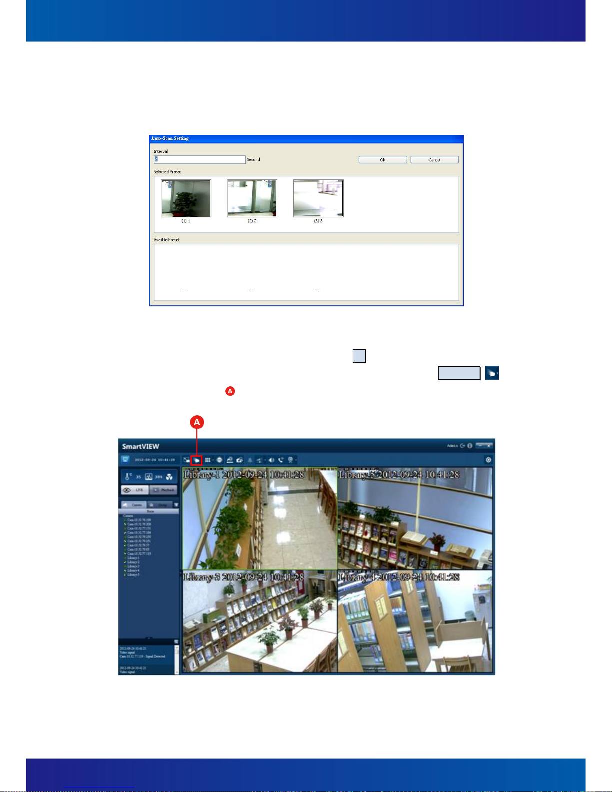
(D) In the Auto-Scan Setting dialog box, users can change the interval of scanning.
(E) Users are also able to drag and drop one or some preset position(s) from the
Available Preset to the Selected Preset.
Figure 4-15
(F) After completing the above steps, click the OK button.
(G) You may start / stop the Auto Scan function by click the button Sequence
(Figure 4-16, ), which is located at the top part of the Live View page.
Figure 4-16

46
4.8 Screen Layout
In the main page, click the icon (Figure 4-17, ) to pop-up a layout box. Users are able
to select a specific layout (1, 4, 8, 9, 16, and so on) in this layout box. Users can also set
specific real-time channel video to "full screen", or change every video displayed by "group"
or "sequence" playback.
Figure 4-17

47
4.9 Event Display
(1) Real-time logs display
User is able to see latest event logs on the main console of live view page’s left down corner
(Figure 4-18 ) and can enlarge the log display area to see more logs at a time by clicking
the button (Figure 4-18 ) .
Figure 4-18
(2) View historical events
By clicking the button at Figure 4-18 the “View Event History” window will pop out. Use
can enter search criteria include start/end date/time and event type, event status, device
name, and device port (for DIO-related events). When all search criteria is set, click Search
and results will be displayed.
If user wants to export a report for event logs, click Save and all logs user found can be
exported as an Office Excel file. If user wants to print out logs, just click Print.
Figure 4-19

48
All types of event user can search is as Table 4-1.
Event type
Event status
System
System leave, application startup, exit
application, change configuration, create server
fail
Login
Log in, log out, authentication fail
Record
Recording space full, recording storage regain
space, record failed
Connect
Remote view connected/disconnected, remote
play connected/disconnected, RTSP remote client
connected/disconnected, RTSP playback
connected/disconnected
Motion/Sensor
/Manual record
(by device)
Video signal
Video loss, video detected
E-Mail/SMS/FTP
Sent successfully, fail to send
Table 4-1

49
5 System Settings
5.1 System Configurations
Click the Setup icon ( ) which is located at the Live View page (Figure 5-1, ) and a
dialog window which is titled Configurations will be pop-up (Figure 5-2). Users are able to
set system configurations as the following:
Figure 5-1
(1) Shutdown the system when program exit (Figure 5-2, )
Once this setting item has been checked, the computer system will be automatically
shut down (power-off) after the program is exited.
(2) Host Name (Figure 5-2, )
This name will show on the central management system NVMS (Network Video
Management System), you can use the name to recognize which SmartVIEW NVR once
you have many SmartVIEW NVRs need to manage.
(3) Save Interval (Figure 5-2, )
This value defines the file length (in minute) of each video data file. The default value is
5 minutes and 8 types of length (1 / 3 / 5 / 10 / 15 / 20 / 25 / 30) are available. For
example, if this configuration has been set to 3 minutes, the SmartVIEW system will
create a new recording data file every 3 minutes (per each available channel).

50
(4) Auto Login (Figure 5-2, )
If this configuration is enabled, the SmartVIEW system will be login with the selected
account after each starting of the operation system. The installation will automatically
create a default account (with an “Administrative” permission) whose user name is
“Admin” and the password is “1234”, users will need to login with an authorized
account and password at each system starting, if this configuration has not been
checked.
(5) Enable Remote Reboot (Figure 5-2, )
If this configuration is enabled, any HTTP connection with the input password will
trigger system to reboot. Ex.:
A. http:// SmartVIEW IP address {:Port Number} / Reboot.cgi
B. Input the correct password.
C. The operation system will be rebooted.
(6) Reboot (Figure 5-2, ): Users can configure the SmartVIEW system to automatically
reboot on a weekly day and time. If this configuration is enabled, please do not set any
password for the default login account unless you do not want the SmartVIEW system
be automatically logged in after the SmartVIEW system rebooting.
Figure 5-2
Notice: Any changes in this Configurations Page won’t be saved until the OK button has
been clicked.

51
5.2 Storage Settings
To add, modify, delete storage setting groups for streaming data file. Instructions:
Click the Setup icon ( ) and a dialog window which is titled Configurations will be
pop-up. Click System / Storage in the tree view item, (Figure 5-3) to adjust the following
configurations:
(1) Max. Event Record Days
The number of days (1~365) for the video recording files saving. Once any recording
file has been kept longer than the duration user set, it will be deleted automatically by
the SmartVIEW system.
(2) Snapshot folder
The folder for saving snapshot pictures.
Figure 5-3
(3) Add Storages
Storage Media Setting:Set a path for recording data files saving. To click the Add
button, a dialog box Storage Device will be pop-up (Figure 5-4). To check the items
of the Storage table to assign partitions to be storages and to check the items of the
Information table to assign cameras’ streaming to be stored in this storage group.
Recycle:If this item is checked, once the available spaces of the storages are less
than the settings value (Storage Reserved Size), the older recording files will be
deleted automatically by the SmartVIEW system with the deleting unit of one hour.
(Figure 5-4, ).

52
Storage Only for Event Clip:If this item is checked, the recording files would be only
saved while any event occurred. (Figure 5-4, )
Figure 5-4
(4) Modify Storages
Select one of the storage device in the Storage Lib (Figure 5-3, ) which you want to
modify, and then click the Edit button, a dialog box Storage Device will be pop-up
(Figure 5-3). Modify the settings (just like the “Instruction (3): Add Storages”
described) and click the OK button finally to apply settings.
(5) Delete Storages
Select one of the Storage Device in the Storage Tab which you want to delete, and
then click the Delete button, a confirm dialog box Storage Device will be pop-up
(Figure 5-5). Just click the Yes button to process the deleting or click the No button to
back the last page.
Figure 5-5
Notice:For each camera which is enabled to record, please make sure that each
camera is assigned with proper storages.

53
5.3 User Account Management
To add, modify, delete “User” and “Authority Group”.
Instructions:
It is recommended to create some authority groups before creating users, and then assign
users to the specific authority groups. To do these, you will need to click the Setup icon
( ) and a dialog window which is titled Configurations will be pop-up. Click System /
Authority Group in the tree view item, (Figure 5-6) to adjust the following configurations:
Figure 5-6
(1) Add Authority Groups
The Authority Groups can be regarded as the classification of user privileges; users can
achieve permissions management through inheritance from different Groups. Once the
permissions of an Authority Group are changed, the permissions (channel permissions,
system privileges) of all the users that inherited from the Authority Group are also
changed.
(2) If a specific Authority Group is deleted, all the users that inherited from the Authority
Group are also deleted unless there is any the user has been assigned with any
individual permission and it will be remained.
(3) There is a special Authority Group, which is named “Supervisor” and it has been
already created by the SmartVIEW system, which won’t be listed in the “Authority
Group” page but the “Authority Group” of the “User” page.

54
(4) To create / modify an Authority Group, please refer to the following steps:
A. Enter the “Name” for the Group in the “Group Name” field.
B. Set Permissions for Channels – In the “Channel authorization” table, users are able
to assign permissions independently for each channel. The permissions include:
(A) Local Preview:Be authorized to open the local real-time video. This permission
is required to browse the local snapshot pictures.
(B) Local Playback:Be authorized to operate the local playback.
(C) Local PTZ:Be authorized to operate the local PTZ controlling. The permission of
“Local Preview” is required to authorize this permission.
(D) Remote Preview:Be authorized to preview the video this channel remotely.
The right of browsing snapshot remotely will also be granted.
(E) Remote Playback:Be authorized to operate the playback remotely.
(F) Remote PTZ:Be authorized to operate the PTZ controlling remotely. But the
permission of “Remote Preview” has to be granted first in order to enable this
permission.
(G) Local Data Export:Be authorized to local export data (Recording data backup,
save snapshot, print snapshot, saving video as AVI files). But the permission of
“Local playback” has to be granted first in order to enable this permission.
(H) Remote Data Export:Be authorized to export data (Recording data backup,
save snapshot, print snapshot, saving video as AVI files) remotely. But the
permission of “Remote playback” has to be granted first in order to enable this
permission.
Notice: Users are able to check all the permissions by checking the check box
which is nearby the channel number (Figure 5-6, ). Users are also able to
check all the channels to grant a specific permission by clicking the check box
which is near by the permission (Figure 5-6, ).
C. Set Permissions for System – In the Authorization table (Figure 5-6, ); users are
able to grant permissions for the SmartVIEW system operating. The permissions
include:
(A) System Shutdown:Be authorized to exit the SmartVIEW system.
(B) View Log:Be authorized to browse the event log of the SmartVIEW system.
(C) Export Log:Be authorized to export (saving as, printing) the event log of the
SmartVIEW system.
(D) Local Setup:Be authorized to change the configurations of the SmartVIEW
system.
(E) Local DO Control:Be authorized to control the digital output devices of the
SmartVIEW system.

55
(F) Remote Setup:Be authorized to change the configurations of the SmartVIEW
system remotely.
(G) Remote DO Control:Be authorized to control the digital output devices of the
SmartVIEW system remotely.
D. Duplicate Authority Groups
If you want to create an Authority Group which is similar to any existing Authority
Group, you can duplicate a new Authority Group from the existing one first, and
then modify the settings for the new one. The steps as the following:
(A) Tap the existing authority group you want to duplicate.
(B) Enter a new name for the new Authority Group in the Group Name field.
(C) Click the button Copy , and a new Authority Group would be successfully
created (duplicated).
(D) Tap the new Authority Group which is just been created, adjust the permission
settings of channels and system.
(E) Click the button Update to complete and apply the operation.
E. Update Authority Groups
To modify an existing Group, the steps as the following:
(A) Select the item which is to be modified first
(B) Adjust the permission settings of channels and system.
(C) Click the Update button to apply the setting.
(5) Add a user (Figure 5-7)
Each user must be inherited at least from one Group (or more than one Group). All of
the inherited permissions are granted (union operation) and cannot be removed. A
user is not only granted with inherited permissions but can also be granted with
non-inherited permissions. Non-inherited permissions can be granted or removed to
any users. The inherited permissions do not affect the non-inherited permission unless
the user is operating actions which involved non-inherited permissions.
A. Enter the Basic Information of User (in the Base Data tab) (Figure 5-7, )
(A) User Name:The name of account. Alpha letters, numbers, special symbols
(1~50 characters) are accepted.
(B) Password:The password of account, 1~50 characters are accepted.
(C) E-Mail:The e-mail address of the user.
(D) Phone number / Mobile Phone Number:Only numbers (0~30 characters) are
accepted.

56
Figure 5-7
(E) Once you complete the above items, please select at least one Authority
Group in the Authority data tab, and then click the Add button to create a
new account. (Figure 5-8, )
(F) You can select an account which is listed in the table Authority Information
(Figure 5-8, ) and then modify settings for updating.
(G) You can also select an account which is listed in the Authority Information
table and click the button Delete to delete it.
Figure 5-8

57
B. Set Information of Permissions
(A) Select inherited permissions of Authority Group
Check one or more (at least one) Authority Group from the Authority Group.
(Figure 5-9, ).
(B) Grant additional non-inherited permissions
Check the non-inherited permissions from the Channel Authorization (Figure
5-9, ) and Authorization. (Figure 5-9, ).
Figure 5-9
(C) Duplicate accounts
If you want to add a new account by copying permissions and other settings
from an exist account, you may select the account which you want to duplicate
and modify the user name and finally click the button Copy to complete the
account-duplicating.
(D) Delete accounts
Select the user which you want to delete and click the button Delete, and then
click the button Yes in the confirmation dialog box (Figure 5-10) to confirm the
deleting.
Figure 5-10

58
(E) Update accounts
Select a user which is to be updated, modify the information and click the
button Update to apply the change.

59
5.4 Hardware Monitoring
The SmartVIEW system provides monitoring of the CPU temperatures and fan status.
Instructions:
Click the Setup icon ( ) and a dialog window which is titled Configurations will be
pop-up. Click the tree view item, System / H/W Monitor (Figure 5-11), to adjust the
following configurations:
(1) Max CPU Temperature:The high-temperature warning for CPU. The default value is 80.
(Figure 5-11, )
(2) Temperature Unit:Celsius (
o
C) or Fahrenheit (oF). (Figure 5-11, )
(3) Fan Speed:If this item is checked, the system will automatically get real-time speed of
the fan; (Figure 5-11, )
(4) System Fan Monitor:If this item is checked, the SmartVIEW system will alert users while
any speed of fan is less than the setting value. (Figure 5-11, )
Figure 5-11

60
5.5 IP Camera Management
Click the Setup icon ( ) and a dialog window which is titled Configurations will be
pop-up. Click the tree view item, IP Camera (Figure 5-12), to adjust the following
configurations:
(1) Manually add an IP camera (Figure 5-12):
Vendor / Model:Specify a proper vendor and model.
Channel / Camera ID:The SmartVIEW system will automatically assign these two
items.
IP Address:The IP address for the connected IP camera.
Camera Name:A name or description for the IP camera.
Account / Password:The account and password for the IP camera.
After complete the above items ( to ), users are able to get the profile of the
specific camera by click the button Get IP Camera Profile .
Record Stream / Preview Stream:Select proper properties for the record stream
and preview stream. The values of properties would be just noticed as “Stream 1” /
“Stream 2” unless users click the Get IP Camera Profile.
Specify a proper storage for the IP camera.
Finally, click the Add IP Cameras to apply the above settings.
Figure 5-12

61
(2) Automatically Find IP Cameras:
A. Click on the Find IP Cameras (Figure 5-12, ) button, a wizard named Add Camera
will be started. The wizard is able to help users to easily discover cameras which
are connected to the network. To start the discovery, just click the 00000icon
(Figure 5-13, ). After few seconds, any available camera will be listed in the
table. By checking the corresponding check-box, users can not only add them to be
a managed IP camera but also specify the default setting of Recording (Figure
5-14).
B. In each step of this wizard, users are able to click the icon to switch next page,
click the icon to back to the previous page, click the icon to cancel and
close the wizard, or click the icon to finish the wizard and apply changes.
Figure 5-13
Figure 5-14

62
C. In the next step ○
2
of the wizard (Figure 5-15), users are able to setup the default
options of cameras. All these settings will also be modified later.
Recording/Preview stream:Choose a stream for previewing or recording from
available streams of a channel.
Motion Detection:To enable full-area motion detection or no motion detection.
Audio Recording:To enable audio recording or not.
Recording Mode:Choose to enable full-time recording or event recording
(with motion detection, DI events etc.).
Figure 5-15
Storage: Choose a specific storage media for recording. (This column would not
be displayed on the first time running of Installation Wizard.)
Figure 5-16

63
D. In the next page ○
3
of the wizard (Figure 5-16), all cameras to be added which
user checked in the page ○1 and their option settings would be listed in the table
for confirming. Users are able to modify those settings or finish the procedure.
E. Users are able to click the (Figure 5-17) icon which in the Live View page to
open this Discovery Wizard.
Figure 5-17
(3) Modify the IP Camera settings:
A. Connection (Figure 5-18).
(A) Click at the main page, choose a channel and choose on the Connection
Setting button a dialog box Camera Connection Setting will be pop-up (Figure
5-19). Users can modify the IP Address, HTTP Port, Account, and Password,
and finally click the OK button to complete the modification.
Figure 5-18

64
Figure 5-19
(B) Click on the Camera Setting button, the Web user interface of the camera will
be opened (Figure 5-20), after editing, click Save and close the internet
browser.
Figure 5-20
(C) Click the Delete Camera button, a confirm dialog box will be pop-up to confirm
the deleting (Figure 5-21). Check for the deletion-related items and click Yes to
delete the selected camera according to user’s requirement.

65
Figure 5-21

66
B. General (Figure 5-22)
Figure 5-22
Camera Enable:When checked, the channel will be activated.
Camera Name:A name or description for the camera.
Font Display Size, Font Display Color:The font size and font color settings for
the OSD on the real-time video.
Record Stream:To specify a proper stream for recording
Preview Stream:To specify a proper stream for previewing.
Video Record Enable:Enable or not to record the video.
Audio Record Enable:Enable or not to record the audio.
Record when event occurred only:If this item is checked, the recording won’t
be started unless any event occurred.
PTZ Enable:Enable or not the controlling of PTZ for a speed dome camera or a
c amera with a PT Head.
Pre-record time / Post Record time:It defines the length of time for event
recording. The system default value is 3 seconds for pre-recording and 10
seconds for post recording. This function usually works with the motion
detection or other events related to cameras. Once any event occurred, 3
seconds of video will be recorded before the occurring time of event (can be
set between 0~10 seconds), and 10 seconds of video will be recorded after
the occurring time(can be set between 0 and 3600 seconds), in this example,
the entire length of recording is totally 13 seconds.

67
Record Schedule:Users can specify the recording schedule by weekdays or
dates (Figure 5-23), the default value is always record, select Schedule mode
first, you may use mouse to hold the edge of time bar (Blue for normal
record, Yellow for event record) to change the time become shorter or
longer (Figure 5-24), and then click OK button to save the new schedule.
Figure 5-23
Figure 5-24

68
C. Motion:(Figure 5-25).
Motion Enable:To check it to enable the motion detection function.
Local (Software) or IP camera’s Motion Detection:You may select the motion
detection event source from Camera or SmartVIEW to operate that.
Event Interval Time:If several events occurred within Event Interval Time, all
of the events will be treated as a single event. This default value is 10 seconds
and can be set between 0 ~ 3600 seconds.
Sensitive:This setting defines the sensitivity of the motion detection. This
default value is 80 and the value can be set between 1~100. The higher value
means the higher sensitivity.
Add Action Zone:Click this button to create a zone for motion detection.
Select Whole Zone:Click this button to set the whole area on the video
become detection zone.
Delete Action Zone:Click this button to specify a zone which is disabled for
motion detection.
Delete All Zone:Click this button to disable all motion detection zones in the
picture.
Motion detection schedule:To set when to enable/disable the motion
detection according to weekday/hours or calendar date. (Refer to Figure 5-26)
Notice:One channel can only have one detection zone; therefore no matter
how many zones are drawn in a channel, they will all be regarded as one
irregular-shaped zone.
Figure 5-25

69
Figure 5-26

70
5.6 Group Settings
User can create, update, duplicate, and delete channel groups in this section. Instructions:
Click the Setup icon ( ) and a dialog window which is titled Configurations will be
pop-up. Choose Group in the function tree (Figure 5-27) to adjust the following
configurations:
(1) Add a group
Group Name:
Input a name for the Camera Group.
Select Camera:
Users can select several cameras join the group by simply dragging a camera
which is listed in the Camera list and dropping it in the Select Camera list. Repeat
this drag-and-drop process until you have selected all cameras you want to be in
this group, and finally click the Add button to complete the operation.
Figure 5-27

71
(2) Duplicate Groups
Select the group (which is listed in the Group list) you want to duplicate and click on
the Copy button to create a new group, and then you can assign a new name for the
new group.
(3) To delete the group
Select the group (which is listed in the Group list) you want to delete and finally click
on the Delete button to delete it.
(4) Update Group
Select the group (which is listed in the Group list) you want to update, modify the
contents, and then click the Update button to update the group information.
72
5.7 Sequence Settings
To provides the “Recursive Playing” function across camera groups. The “Sequence” can be
created, updated, duplicated, and deleted by users.
Instructions:
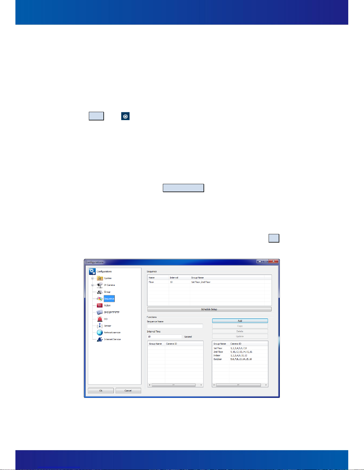
Click the Setup icon ( ) and a dialog window which is titled Configurations will be
pop-up. Click the tree view item, Sequence (Figure 5-28), to adjust the following
configurations:
(1) Create Sequences
A. Sequence Name:A name or a description of this Sequence mode.
B. Interval Time:This time is defined the time how long to wait to switch to the next
Group (Camera Group) to display.
C. Schedule Setup:Click the Schedule Setup button, users can assign different
Sequences by a weekly or daily schedule (Figure 5-29). Therefore, desired
sequence mode will be automatically started and stopped in the period defined by
the user.
D. Enter Sequence Name and Interval Time for the new Sequence and drag Groups
from the right list and drop them into the left list, and finally click the Add button
to complete the creation of Sequence.
Figure 5-28

73
Figure 5-29
(2) Duplicate Sequences
Select the Sequence (which is listed in the Sequence list) you want to duplicate and
click on the Copy button to create a new Sequence.
(3) Delete Sequences
Select the Sequence (which is listed in the Sequence list) you want to delete and click
on the Delete button, a confirm dialog box Sequence Setting will be pop-up (Figure
5-30), click Yes to complete the deletion or click No to cancel this deletion.
Figure 5-30
(4) Update Sequences
Select the Sequences (listed in the Sequences list) you want to update, modify the
contents, and finally click the "Update" button to update the Sequences information.

74
(5) Start Sequencing
In the Live View page, click the icon (Figure 5-31, ), and then the list of available
sequence modes will show up, just select one to start the sequence. Click on the mode
again to stop it. (Figure 5-31)
Figure 5-31

75
5.8 SMS / Email Settings / FTP Settings
Set configurations for SMS, E-Mail, and FTP. If any Action Definitions involved SMS, SMTP, or
FTP, these configurations must be set correctly. Instructions:
C lick the Setup icon ( ) and a dialog window which is titled Configurations will be
pop-up. Click the tree view item, SMS\SMTP\FTP (Figure 5-32), to adjust the following
configurations:
Figure 5-32
(1) SMS settings
A. SMS:SMS function is enabled when checked,
B. Serial Port Number:Select a port can be used to send SMS.
C. Baud Rate:The system defaults to 115200, system provides 2400 / 4800 / 9600 /
19200 / 38400 / 57600 / 115200 / 230400 a total of eight kinds of users based on
the need for choice.
(2) SMTP (E-Mail) settings
A. Host Name:Enter the FQDN (Fully Qualified Domain Name) of the host.
B. Port:Enter the port number of the host.
C. Authentication Mode:“True” (YES) or “FALSE” (NO) to authenticate the account
while sending.
D. Account / Password:Username / Password.
76
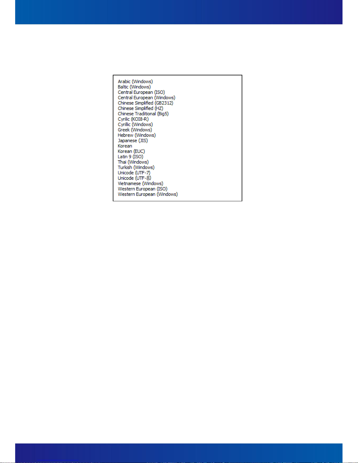
E. Language Code:The encoding code. The system default is Unicode (UTF-8) and the
following are available:
Figure 5-33
F. Sender E-Mail:Users can assign an e-mail address of the sender here.
G. Sender name:Users can assign a name of the sender here.
(3) FTP settings
A. Host Name:Enter the FQDN (Fully Qualified Domain Name) of the host.
B. Port:Enter the port number of the host.
C. Account / Password:Username / Password.
D. Remote Directory:The name of a directory which is the destination directory for
uploading. This directory will be automatically created in the home directory.
E. Passive:Check this check box if the FTP site is in Passive Mode.

77
5.9 DO (Digital Output) Settings
Configure digital output devices that are connected to IP Cameras. For example, speakers,
alarms, etc. Instructions:
Click the Setup icon ( ) and a dialog window which is titled Configurations will be
pop-up. Click the tree view item, DO (Figure 5-34), to adjust the following configurations:
(1) Add a device
Device Name:Select a name of the master device which DO device connected to
IP camera.
Device Port:The port number of the master device.
Device Description:Descriptions of the DO device.
Click the Add button to add a new device.
Figure 5-34

78
(2) Delete the device
Select a DO Device which is to be deleted from the DO Device list, click the Delete
button, a confirmation dialog box (Figure 5-35) will be pop-up, just click the Yes button
or complete the deleting.
Figure 5-35
(3) Update the device
Select a desired DO Device which user need to updated from the DO Device list, modify
the contents, and then click on the Update button to complete the updating.

79
5.10 Sensor Settings
This instruction describes how to create, delete, or update the configurations about sensors
(ex., Door Sensor, Smoke Detector, etc.):
Click the Setup icon ( ) and a dialog window which is titled Configurations will be
pop-up. Click Sensor on the tree view items (Figure 5-36) to adjust the following
configurations:
(1) Add a sensor device
Enable:If this box is un-checked, SmartVIEW will not process the notification
from this sensor.
Device Name:Select a name of the master device which DI device physically
connected to like IP camera.
Device Port:The port number of the master device.
Device Description:A description for the sensor device.
Add:After finishing of the above settings, users can click the Add button to add a
new sensor device.
Mode:Users are able to select one mode to define a time segment (weekly or
specific days), a description, an interval, and a delay time for the sensor.
Figure 5-36

80
(2) Remove the sensor device
Select a sensor device which is to be deleted from the Sensor Device list first, and then
click the Delete button, a confirmation dialog box will be pop-up (Figure 5-37). Just
click the Yes button to complete the deleting or click the No button to cancel.
Figure 5-37
(3) Update a sensor device
Select a sensor device which is to be updated first, modify the settings, and finally click
the Update button to complete the updating.

81
5.11 Event Action Settings
Define a variety of response actions for every types of event. For example, to turn on a siren
linked on an IP camera for 10 seconds while any motion detection occurred, or to send an
e-mail to the administrator to alert him that a hard drive disk is going to be broken, etc…
And one event can be set to trigger multiple actions!
Instructions:
Click the Setup icon ( ) and a dialog window which is titled Configurations will be
pop-up. Click Action (Figure 5-38) to adjust the following configurations:
Figure 5-38

82
(1) Description: A name or a description of the Action.
(2) Event Type: The type of the trigged event (Table 5-1). For Motion Detection, Sensor,
and Camera Signal, the items Device Name and Device Description are required.
Event Type
Status
Record
Recording space full
Recording storage regain space
Motion
Motion
Sensor
Sensor
Video Signal
Video loss
Video Detected
Table 5-1
(3) Device Name:A name of the device that the event belongs to.
(4) Device Description:A name of the device that the event belongs to.
Notice: Please refer to Section 5.100 Sensor Settings.
(5) Action Interval:If the same event occurred within a period of event interval more than
one time, all of the events will be treated as a single event. This default value is 10
seconds and the value can be set between 0 ~ 3600 seconds.
(6) Action Setup:Click on the Action Setup button to open a dialog box titled Action Item
Setting (Figure 5-39 ). Users can set an action definition by selecting actions.
A. DO:Digital Output, to trigger external digital devices attached on IP camera. For
example, siren and alarm light, speaker, etc.
Notice: Refer to Section 0 DO (Digital Output) Settings.
B. PTZ:To drive the specific speed dome camera to aim a specific position for a
specific time.
Notice: Refer to Sections 4.7 Speed Dome Camera Control and Section 5.11 Event
Action Settings (PTZ related information)
C. E-Mail:To send an email to relevant person.
D. SMS:To send a SMS text message to relevant person.
Notice: Refer to Section 0 SMS / Email / FTP Settings.
E. HTTP Call:To perform a CGI calling to a specific HTTP web site.
F. Video Clip:To start saving a video clip of a specific camera.
G. Snap Shot:To snapshot a picture and save it to a specific folder.

83
H. Play Sound:To play a user-defined sound.
I. Display:To pop-up a window with user-defined live video of a channel with
optional auto-countdown to close window; or to display the real-time videos of a
specific camera or a camera group for a user-defined time replacing the original
previewing video channel temporarily.
J. Execute App:To execute a specific application on this local server.
Figure 5-39
(7) After setting, finally click the Add button to complete the creation.
(8) If user wants to add another action for this event, click the empty row on action list
(Figure 5-39 ) and then repeat the process of adding a new action.
(9) Duplicate Action:
Select the Action which you want to duplicate, modify the Action Settings, click the
button Copy, you can create another new Action.
(10) Delete Action:
Select the Action which you want to delete, click the button Delete, and then click the
Yes button in the confirmation dialog box to confirm the deleting.
(11) Update Action:
Select the Action which you want to update, then modify the Action Settings and click
the button Update to apply the change.

84
6 Playback & Log search
6.1 Playback
Users can playback and query out desired time spot by date/ time, events, snapshots, and
bookmarks, or process an “Smart Search” by motion detection analysis toward recording
file.
Instructions:
In the Live View page of the SmartVIEW system, click the Playback icon ( )
and the page will be switched for the Playback View page (Figure 6-1, ).
Figure 6-1

85
Figure 6-2
Notice: An authorized permission is required to do the following about playback operation.
(1) Date / Time Search
A. Click on the Search By Time icon ( ) (Figure 6-2, ), pop-up the Search By
Time dialog box (Figure 6-3)
Figure 6-3

86
B. In the calendar box (upper part of the Search by Time), the date which is marked
with green background indicates there are some recordings have been saved.
C. In the camera-time-schedule list (lower part of the Search by Time), the time
segment which is marked with blue background indicates the corresponding
camera has recording files at the time segment. There is a vertical blue line which
indicates the base time of the playback.
D. Users are able to move the blue base time line to any time, and then click the
Search button, the Search by Time dialog box will be closed and the base time of
the playback is changed correspondingly.
E. Press the icon (Figure 6-2, ) will start playback of the video.
(2) Event Search
A. Firstly, select a camera which is to be searched on the main console of playback.
B. Click on the Event Search button, Search by Event dialog box will be pop-up
(Figure 6-4).
C. After specifying the condition (date, time, event type, etc.), click the Search button,
it will list the event log about the camera.
D. For the event log, there are four types:
Motion:Be trigged by motions detected.
Sensor:Be trigged by sensors active.
Video Signal:Be trigged by videos missed or recovered.
Manual Record:Be trigged by users’ Manual Recording.
Figure 6-4

87
E. Select an event log and click the Select button, the Search by Event will be closed
and the playback time will be jumped to the time of the event, and automatically
start to play.
F. If save video clip for this channel was set when setting event action, user will be
able to see a “ ” mark next to the event log in the Search by Event dialog box.
Then user can directly select on the log with video clip and click the Play button, a
video window will pop out and the event video clip will aquatically start to play.
(3) Smart Search
It can help users to analysis and check a specific area in the recording files with a
specific time segment.
To start an Smart Search process, users should select a camera which is to be analyzed
first, and then click the Search By Smart in the Playback View page (Figure 6-5, ),
and assign the conditions (date, time, sensitivity, and interval) in the Search By Smart
{name of camera} dialog box.
Figure 6-5

88
Figure 6-6
A. Select Motion Area:Click this button to define the areas for motion detection
(Figure 6-7).
To add a new detecting area, check the Add Motion Zone check-box first, and
then start to assign which part to be added.
To delete a detecting area, check the Delete Motion Zone check-box first, and
then start to assign which part to be deleted.
To add all the detection area, click on the Select Whole Motion Zone button.
To delete all the detection area, click on Delete All Motion Zone button.

89
Figure 6-7
B. After assigning the detecting zones, click on Search button (Figure 6-8, ), you
can analyze the selected zone on the recording video and search results will be
displayed on the dialog. Click on one of these results, and click on select button
(Figure 6-8, ) to return to main console of playback and automatically start to
play from the event time spot.
C. If you want to stop the event searching process, click Stop (Figure 6-8, ) button.
Figure 6-8
90
Figure 6-9
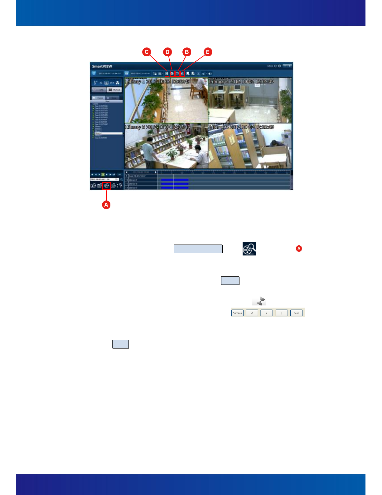
(4) Thumbnail search
A. In the playback view page, select a channel you want to execute thumbnail
search. And then click the Thumbnail Search icon ( ) (Figure 6-9, ). A
“Thumbnail search {Camera name}” dialog box will be pop-up. (Figure 6-10)
B. Select the date and start time for this search, and enter a valid interval (the time
interval between each thumbnail) and click on Search button.
C. Thumbnails will be displayed on the left upper side of the dialog with their time
under the image. If thumbnail can’t be retrieved, the icon ( ) will be shown.
D. Video preview: Click on any thumbnail and click
for video previewing from the time spot of that thumbnail with
forward/backward playing, pause, and go to next or previous time spot.
E. Click Select and you will go back to the Playback View page, the time bar will be
jumpped to the time of the selected thumbnail and automatically start to play.

91
Figure 6-10
(5) Print
In the Playback View page, select a camera from one of playing channels, and then click
on the Print icon ( )(Figure 6-9, ), it will bring on an Image Edit {camera name}
dialog box (Figure 6-11), modify the following information, then click the "Print" button,
and select Print image size, you can have the picture print out.
Rotation:180 degree rotating for this photograph.
Crop:Select a region on the photo by dragging & dropping, then click on this button,
this area can be enlarged and rest of the area will be deducted.
Revert:Restore for the previous change.
Show Date / Name:Put Camera Name and Date / time on the picture.
Save with watermark:User can choose to overlay a watermark on the image. Click
on Watermark and a dialog (Figure 6-12) will be pop-up with all related
configuration. Afterward, click “ok” to save all configurations and close the dialog.
Then if user check on “Show Watermark” check box, the image will be save with
watermark successfully.
HSL effects:To adjust the picture’s Brightness and Saturation instantly. Click "Reset"
button to restore to default.
RGB effects:To adjust the picture's color scheme with the level of red, green and
blue. Click "Reset" button to restore to default.

92
Print:After all above settings are done, press “Print”, select the size of the actual
printing, and click “ok” to activate the printing.
Figure 6-11
Figure 6-12
Notice: To use the Photo Print functions, the privilege of local data export is required.
(6) Save Video (as AVI)
In the Playback View page, select a camera from one of playing channels, and then click
the Save Video icon ( ) (Figure 6-9, ), pop-up Save Video {camera name}

93
dialog box (Figure 6-13). After finishing the following settings, press Save and set the
storage path, the AVI file will be saved successfully.
To set the start/end date/time of the video saving period, user can input the
date/time manually, or select from event’s time, from manual snapshot search’s
time, or from a bookmark.
Displays watermark: Save AVI movies with watermark overlay. Check the Show
Watermark check box, and click Watermark for detail settings.
Display Name / Date: Check for displaying the camera’s Name and Date/time on
the image.
Notice: To enable the function of Save Video, the right of “local data export” must be
granted first. The progress of saving and the date/time of on-going data will be
displayed in the “Progress” column.
Figure 6-13
(7) Save image
In the playback page, select a camera from one of playing channels, and then click on
the Save Image icon ( )(Figure 6-9, ), it will bring on an Image Edit {camera
name} dialog box (Figure 6-14), modify the following information, then click the Save
button on upper side of this dialog, you can have the picture saved and the dialog will
be closed.
Rotation:180 degree rotating for this photograph.

94
Crop:Select a region on the photo by dragging & dropping, then click on this button,
this area can be enlarged and rest of the area will be deducted.
Revert:Restore for the previous change.
Show Date / Name:Put Camera Name and Date / time on the picture.
Save with watermark:User can choose to overlay a watermark on the image. Click
on Watermark and a dialog (Figure 6-12) will be pop-up with all related
configuration. Afterward, click OK to save all configurations and close the dialog.
Then if user check on Show Watermark check box, the image will be save with
watermark successfully. (Figure 6-12)
HSL effects:To adjust the picture’s Brightness and Saturation instantly. Click Reset
button to restore to default.
RGB effects:To adjust the picture's color scheme with the level of red, green and
blue. Click Reset button to restore to default.
Notice: To enable the function of Save Image, the right of “local data export” must be
granted first.
Figure 6-14

95
(8) Backup
A. In the Playback View page (or Live View page), click the Save Backup icon
( )(Figure 6-9, ), a Backup dialog box will be pop-up (Figure 6-15) with two
options – Back up to the Hard Disk or Burn to CD :
Figure 6-15
B. Click on the Back up to the Hard Disk button will be pop-up Backup to Hard Disk
dialog (Figure 6-16). To set the start/end date/time of the backing up, user can
input the date/time manually, or select from event’s time, from manual snapshot
search’s time, or from a bookmark. If user chooses Burn to CD , the same dialog
will also pop out with only some slight difference (Figure 6-17).
C. Click on Detect Burn Volume, estimated data size according to user’s configuration
will be brought out.
D. Click Burn or Start to backup, the backup will be started and users can check the
backup progress on the progress bar on the lowest side of this dialog.

96
Figure 6-16
Figure 6-17

97
Figure 6-18
(9) Bookmark
Users are able to make bookmarks during video playback when finding any important
moment in the record. Users are also able to jump the playback to a specific moment
which has marked as a bookmark.
A. Add a bookmark (Figure 6-19)
Click on the icon ( ) (Figure 6-18, ), a dialog Add Bookmark will be pop-up.
Enter the name of the bookmark and click Save to save this bookmark.
B. Playback by Bookmark (Figure 6-20)
(A) Click the icon ( ) (Figure 6-18, ). The menu of Bookmark will be
pop-up.
(B) Choose one and press Select, the time axis of playback will be jumped to the
time of the bookmark you selected. Then click the on the Playback View
page, the video will start to playback from the time user selected.
(C) To delete a bookmark, choose a bookmark you want to delete and press
Delete.

98
Figure 6-19
Figure 6-20

99
6.2 Event Log Query
In the Live View page of the SmartVIEW, click on the View Log icon ( ) (Figure 6-21, )
to bring up the View Log dialog box (Figure 6-22). Users are able to query the log with one
or some filters (ex. Date, Start / End time, Event type / status, etc.), and then click Search,
the logs will be brought out immediately. Afterward, users are able to save as CSV format or
print it out.
Figure 6-21
Figure 6-22
 Loading...