

Inglis Washer-Dryer Installation Instructions Manual
If washer/dryer
does not operate...
• Check that the circuit breaker is not
tripped or the house fuse blown.
• Check that power supply cord is plugged
into wall receptacle.
• Check that washer lid or dryer door is
closed.
• Check that the round shipping piece has
been removed.
• Check that controls are set in a running or
When moving the
washer/dryer...
• Disconnect the power supply cord.
Tape power supply cord securely to
washer/dryer.
• Tape the dryer drum to the front panel.
Tape the lint screen in place. Tape the
dryer door closed.
• Wedge a blanket between the tub ring
and cabinet top to restrict tub movement.
• Turn front leveling legs all the way in.
If you need
assistance...
Check your Use and Care Guide for a tollfree number to call, or call the dealer from
whom you purchased this appliance. The
dealer is listed in the Yellow Pages of your
phone directory under ”Appliances —
Household — Major — Service and Repair.”
When you call, you will need the washer/
dryer model number and serial number. Both
numbers can be found on the model/serial
Part No. 3405982
Four-Wire Laundry System
Washer•Dryer – 240 Volt
Installation Instructions
IMPORTANT:
Installer: Leave Installation Instructions
with the homeowner.
Homeowner: Keep Installation Instructions
for future reference.
Save Installation Instructions for local
electrical inspector’s use.
IMPORTANT:
Read and save
these instructions.
Electrical Shock Hazard
Electrical ground is required.
Do Not ground to a gas pipe.
Improper connection of the equipment-
grounding conductor can result in a risk of
electrical shock.
Check with a qualified electrician if you are
not sure this washer/dryer is properly
grounded.
Do Not change the power supply cord plug.
If it will not fit the outlet, have a proper
outlet installed by a qualified electrician.
Do Not have a fuse in the neutral or
grounding circuit.
Do Not use an extension cord with this
washer/dryer.
Failure to follow these instructions could
result in death or electrical shock.
Tools and materials
needed for
installation:
Panel A
level
Phillips
screwdriver
utility knife
duct
tape
Electric Shock Hazard
It is the customer’s responsibility:
To contact a qualified electrical installer.
To assure that the electrical installation is
adequate and in conformance with the
Canadian Electrical Codes, and all local
codes and ordinances.
Failure to follow these instructions can
result in death or electrical shock.
Fire Hazard
For your safety, the information in this
manual must be followed to minimize the
risk of fire or explosion or to prevent
property damage, personal injury or loss
of life.
Do Not use or store gasoline, paint,
thinners and other flammable materials
near washer/dryer. Fumes from such
materials could result in fire or explosion.
Never install washer/dryer up against
draperies or curtains or on carpet. To do
so may result in a fire.
Keep any and all items from falling or
collecting behind the washer/dryer.
Failure to do so may result in a fire.
Replace all access panels before
operating washer/dryer.
Failure to follow these instructions may
result in a fire.
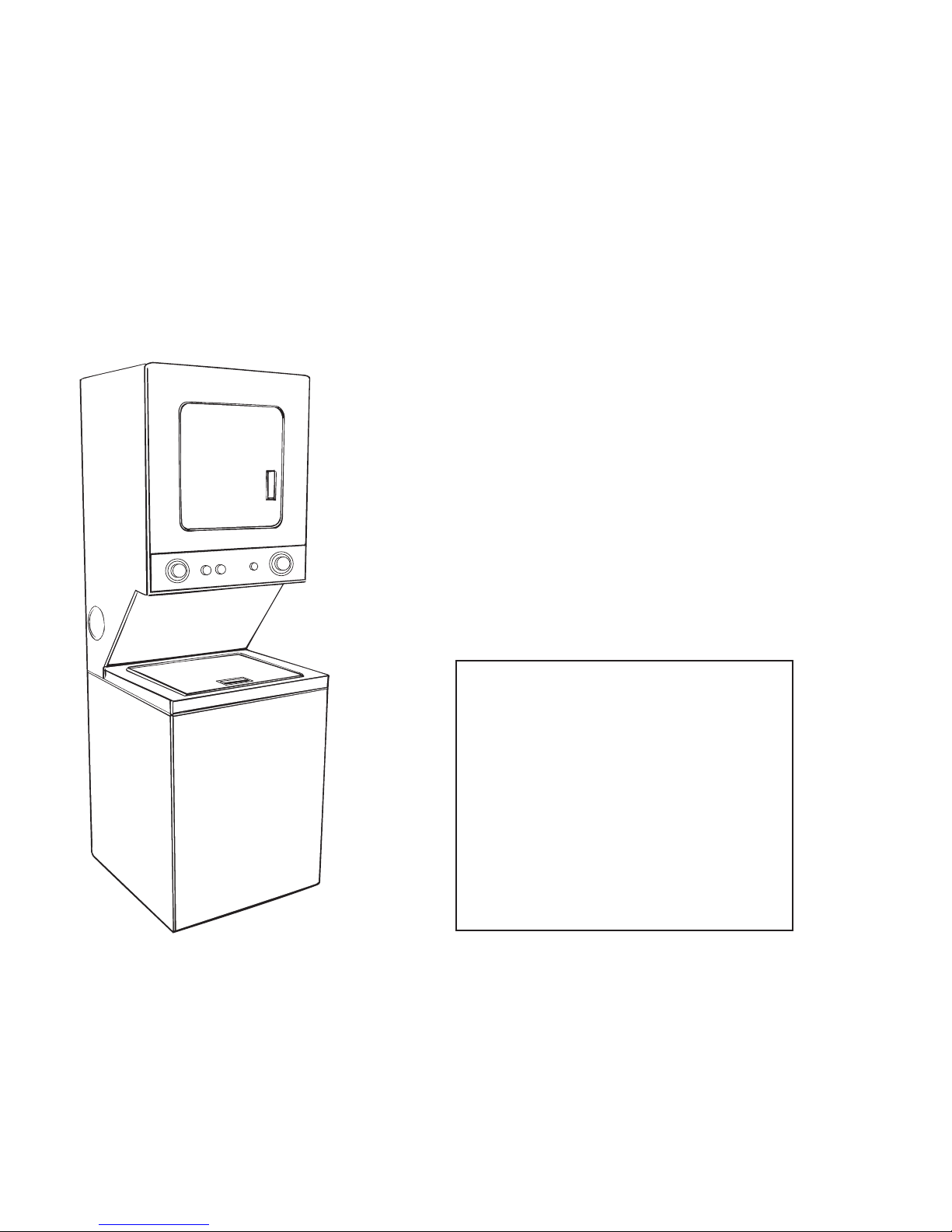
Before you start...
Check location where washer/dryer will be
installed. Proper installation is your
responsibility. The washer/dryer must not be
installed or stored in an area where it will be
exposed to water and/or weather. Make
sure you have everything necessary for
correct installation.
Location should be large enough to fully
open dryer door 90°. (See Panel E for
“Recessed and closet installation
instructions” and “Product dimensions.”)
Check utilities: Proper electrical supply
must be available. See “Electrical
requirements”, Panel A.
Important : Observe all governing
codes and ordinances.
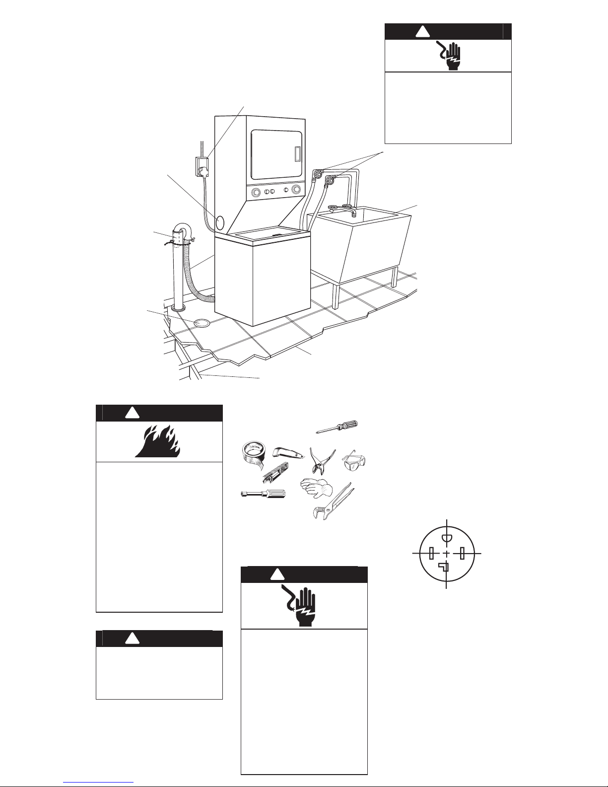
Grounded electrical outlet within (1.5m) 5 ft
of the center rear of cabinet is required. See
“Electrical requirements,” Panel A.
Dryer may be exhausted
from rear or left or right side.
Exhausting through the side
requires Side Exhaust Kit Part
No. 279823. See “Exhaust
requirements,” Panel B.
Standpipe drain system
needs a 5 cm (2 in)
diameter standpipe
with a minimum carryaway capacity of
64.4 litres (14.2 Imperial
gallons) per minute.
Top of standpipe must
be at least 71.1 cm
(28 in) high and no
higher than 121.9 cm
(48 in) from floor.
Floor drain system
requires a siphon
break, Part No.
285320, available
from your authorized
parts distributor.
10.2 cm (4 in)
metal exhaust
duct is required.
Level floor: Maximum
slope under
washer/dryer,
2.5 cm (1 in).
Hot and cold water faucets must be within
1.2 meters (4 feet) of the back of the
washer/dryer and provide water pressure of
34 to 690 kPa (5-100 psi).
Water heater: Set to deliver 60°C (140°F)
water to the washer.
Drain hose
may also be
installed to a
laundry tub
or floor drain
system.
See Panel D.
1/4" socket wrench
or nut driver
Check code requirements. Some codes limit
or do not permit the installation of
washer/dryer in garages, closets, mobile
homes and sleeping quarters. Contact your
local building inspector.
If a longer drain hose is
needed, Drain Hose Part
No. 388423, and Hose
Connection Kit Part No. 285442,
are available from your
authorized parts distributor.
Support: Floor must be sturdy enough
to support washer/dryer weight with
water and clothes of 170 kg (375 lb).
!
WARNING
!
WARNING
!
WARNING
Electrical
requirements
OBSERVE ALL GOVERNING CODES AND
ORDINANCES
1. A four-wire, single-phase, 120/240-volt,
60-Hz, AC only electrical supply is required
on a separate 30-ampere circuit, fused on
both sides of the line. (Time-delay fuse or
circuit breaker is recommended.)
2. This washer/dryer is equipped with a fourwire, 30-amp rated flexible-type power
supply cord. It must be plugged into a
mating 30-amp receptacle (NEMA-type
14-30R). See Figure 1.
Use 30-amp receptacle where local codes
permit flexible-type supply cord (pigtail).
G
Y
X
W
14-30R
4-wire receptacle
Figure 1
SEE RECESSED AND CLOSET
INSTALLATION INSTRUCTIONS
ON PANEL E .
Laundry tub drain system needs
a 75.7 litres (16.7 Imperial
gallons) laundry tub. Top of tub
must be at least 71.1 cm (28 in)
high and no higher than 121.9
cm (48 in) from floor.
Do Not store or operate washer/dryer
below 0°C (32°F) (some water may
remain in washer). Proper operation of
dryer cycles requires temperatures above
7°C (45°F). See Use & Care Guide for
“Winterizing” information.
Injury Hazard
More than one person is required to lift,
tilt, or move this washer/dryer because of
its weight and size.
Failure to follow these instructions may
result in injury.
!
WARNING
slip-joint
pliers that
open
to 3.8 cm
(1-1/2")
minimum
gloves
pliers
safety glasses
Panel B
Exhaust requirements
Fire Hazard
Do Not use non-metal, flexible duct.
Do Not use metal duct smaller than
10.2 cm (4 in) in diameter.
Do Not use exhaust hoods with magnetic
latches.
Check that exhaust system is not longer
than specified. Exhaust systems longer
than specified will:
— Accumulate lint.
— Shorten the life of the product.
— Reduce performance and result in
longer drying times and increased
energy usage.
Failure to follow specifications may result
in a fire.
Do Not exhaust the dryer into a chimney,
furnace, cold air duct, attic or crawl space,
or any other duct used for venting.
Clean the exhaust system every year.
Do Not install flexible duct under wall,
ceiling or floor materials.
Accumulated lint could be fuel for a fire or
cause moisture damage.
Exhausting your dryer indoors is Not
recommended. The moisture and lint
indoors may cause:
— Lint to gather inside and around the
dryer and be a fuel for fire.
— Moisture damage to woodwork,
furniture, paint, wallpaper, carpet,
etc.
— Housecleaning problems and
possible health problems.
Failure to follow these instructions could
result in fire damage, injury or health
problems.
If using an existing exhaust system, clean lint
from entire length of exhaust system. Make
sure exhaust hood is not plugged with lint.
The exhaust system should be inspected and
cleaned yearly.
Replace any vinyl or metallized plastic foil
exhaust duct with rigid metal or flexible
metal duct.
!
WARNING
The exhaust duct can
be routed up, down,
left, right or straight out
the back of the washer/
dryer. Space
requirements are
provided on Panel E
and on the rear panel of
the washer/dryer. Use
the straightest path you
can, to avoid 90˚ turns.
Use duct tape to seal all
joints. Do Not use screws to
secure duct.
10.2 cm (4 in)
rigid metal pipe
is preferred. Plan
installation to use the
fewest number of
elbows and turns.
Metal flexible duct must
be fully extended and supported when the
dryer is in its final position. DO NOT KINK OR
CRUSH THE DUCT. The metal flexible duct
must be fully extended to allow adequate
exhaust air to flow.
Allow as much room as possible when using
elbows or making turns. Bend duct gradually
to avoid kinking. Remove excess flexible
duct to avoid sagging and kinking that may
result in reduced air flow.
For exhaust configurations other than those
listed in chart, the back pressure MUST not
exceed 0.5 cm (0.2 inches) water column at
the back of the washer/dryer. The back
pressure should be checked by a qualified
technician.
For exhaust systems not covered by the
exhaust length chart, see Service Manual,
Part No. 603197, available from your
authorized parts distributor.
Service check: The back pressure in any
exhaust system used must not exceed
0.5 cm (0.2 inches) of water column
measured with an incline manometer at the
point that the exhaust duct connects to the
dryer.
The maximum length using a 5.1 cm x 15.2 cm
(2 in x 6 in) rectangular duct with 2 elbows and a
6.4 cm (2-1/2 in) exhaust hood is 2.4 m (8 ft).
Exhausting the dryer outside is
recommended. Recessed installation that is
not exhausted outside must use Exhaust
Deflector Kit Part No. 694609, available from
your authorized parts distributor. See
“Recessed and closet installation
instructions,” Panel E, for unobstructed air
opening requirements.
If the washer/dryer is installed in a confined
area such as a bedroom, bathroom or
closet, it must be exhausted to the outside
and provision must be made for enough air
for combustion and ventilation. Check
governing codes and ordinances. Also refer
to the “Recessed and closet installation
instructions” on Panel E.
An exhaust hood should cap
the exhaust duct to prevent
exhausted air from returning
into dryer. The outlet of the
hood must be at least
30.5 cm (12 in) from the
ground or any object that
may be in the path of the
exhaust.
10.2 cm (4 in) outlet hood is preferred.
However, a 6.4 cm (2-1/2 in) outlet may be
used with short systems only. A 6.4 cm
(2-1/2 in) outlet can result in longer drying
times than other hood types. For permanent
installation, a stationary exhaust system is
required.
Mobile home exhaust requirements: The
washer/dryer must have an outside exhaust.
If the dryer is exhausted through the floor
and the area under the mobile home is
enclosed, the exhaust system must terminate
outside the enclosed area. Extension
beyond the enclosure will prevent lint and
moisture buildup under the mobile home.
Exhausting the dryer through
the side of the washer/dryer
requires the use of Side
Exhaust Kit Part No. 279823.
Follow kit instructions for
proper exhaust installation.
Mobile home installation
Injury Hazard
More than one person is required to lift,
tilt or move the washer/dryer because of
its weight and size.
Failure to follow this instruction may
result in injury.
!
WARNING
Truck only from the rear to prevent product
damage.
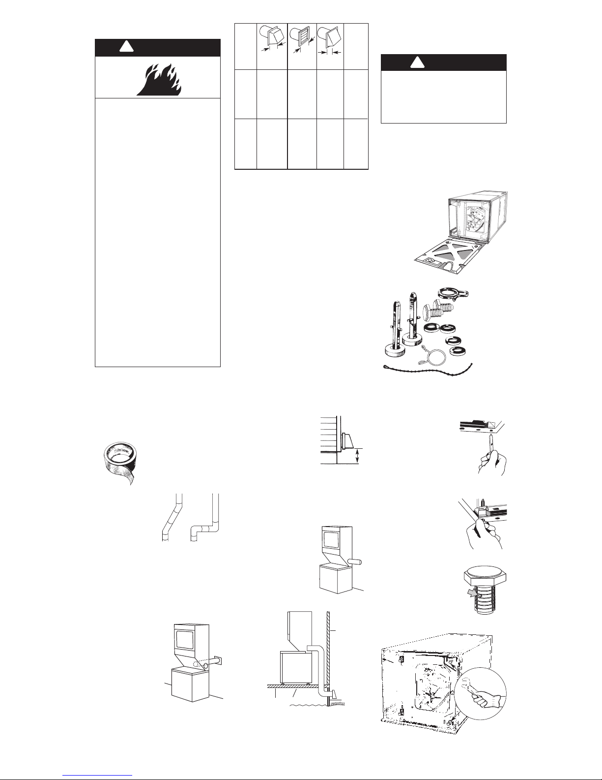
Now start...
With washer/dryer in laundry
area.
• 4 legs
• 1 drain hose
clamp
• 1 plastic
beaded strap
• 4 flat, waterhose washers
• 1 small clamp
rear legs
good
exhaust air flow
better
30.5 cm
(12 in)
minimum
front legs
13.1 m
(43 ft)
10.1 m
(33 ft)
7.0 m
(23 ft)
5.5 m
(18 ft.)
9.1 m
(30 ft)
7.3 m
(24 ft)
4.9 m
(16 ft)
3.1 m
(10 ft.)
12.5 m
(41 ft)
9.5 m
(31 ft)
6.4 m
(21 ft)
5.5 m
(18 ft.)
8.8 m
(29 ft)
7.0 m
(23 ft)
4.6 m
(15 ft)
2.7 m
(9 ft.)
7.3 m
(24 ft)
5.5 m
(18 ft)
3.1 m
(10 ft)
Not
recommended
11.0 m
(36 ft)
7.9 m
(26 ft)
4.9 m
(16 ft)
Not
recommended
0
1
2
3
0
1
2
3
rigid
metal duct
Maximum
length of
10.2 cm
(4 in) dia.
duct
flexible
metal duct
10.2 cm
(4 in)
10.2 cm
(4 in)
6.4 cm
(2-1/2 in)
NUMBER
OF 90°
TURNS
6.With one of the
front legs in hand, check
the ridges for a diamond
marking. That's how far the
leg is supposed to go into
the hole. Start to screw the
legs into the holes in the
front corners by hand.
4.Insert a rear-leveling
leg into the hole in the rear
corner on the bottom of the
washer/dryer. Push leg in until it
snaps into place. Do the same
same thing with the other leveling
leg in the other rear corner.
5.Push up one leg;
check to see that the other
leg goes down. Check the
other leg the same way. (If
legs do not adjust, repeat
Step 4.)
Use slip-joint pliers to finish turning the front
legs until you reach the diamond mark.
2.Remove
shipping cardboard
base.
1.Put on safety glasses and gloves.
Maximum length of the exhaust system
depends upon the type of duct used,
number of elbows and the type of exhaust
hood. The maximum length for both rigid
and flexible duct is shown in the chart.
3.Remove parts from plastic
package. Check that all parts were
included.
floor
skirting
outside
wall
enclosed area
 Loading...