

Ingersoll-Rand P425AWIR, XP375AWIR, HP375AWIR, VHP300AWIR, P600WIR Electrical/electronic Service Manual
...Page 1
ELECTRICAL/ELECTRONIC
SERVICE MANUAL FOR
P425AWIR (7/120)
XP375AWIR (9/110)
HP375AWIR (10/105)
VHP300AWIR (14/85)
P600WIR
HP450WIR
VHP400WIR
Portable Power
P.O. Box 868 -- 501 Sanford Ave
Mocksville, N.C. 27028
www.portablepower.irco.com
Book No. 22235428 (11/03)
Page 2

TABLE OF CONTENTS
SECTION1.......ManualDescription
SECTION2.......GeneralInformationAndOperationalTheory
SECTION3.......ServiceTools
SECTION4.......ElectronicSystemsTroubleshooting
Procedures And Techniques
SECTION5.......SystemSchematicDiagrams
SECTION6.......ElectronicComponent Location Drawings
SECTION7.......IndividualCircuitDiagrams
SECTION8.......ElectricalConnector Information
SECTION9.......ElectricalPartsList
SECTION10......AlertsandShutdownsList
SECTION11......RecommendedSpareParts
SECTION 12 IR Engine....
Book No. 22235428 (11/03)
1()
P425AWIR Family Electrical Manual
Page 3

SECTION 1
MANUAL DESCRIPTION
Thismanualcontainsall of the information concerning the electrical and electronic systems for
theP425 Familyof compressors. It providesall information necessary to service, troubleshoot
and order parts for this machine.
It is organized into 12 sections.
Sections 2 -- 4 cover systems operation and troubleshooting procedures.
Sections 5 -- 7 have location diagrams, drawings of specific circuits and systems schematics.
Section8 hasinformation concerningthe electricalconnectors used,including removaland re-
placement.
Section 9 contains the parts list with ordering information.
Section 10 contains the list of Alerts and Shutdowns.
Section 11 contains a list of recommended spare parts for servicing.
Section 12 contains engine information.
Book No. 22235428 (11/03)
2()
P425AWIR Family Electrical Manual
Page 4

SECTION 2
GENERAL INFORMATION
and
OPERATIONAL THEORY
Book No. 22235428 (11/03)
3()
P425AWIR Family Electrical Manual
Page 5

GENERAL INFORMATION AND OPERATIONAL
THEORY
General
The P425 Family of machines has an electronic
monitor and control system to provide discharge air
pressure control and engine and package monitor
functions. The system uses the WEDGE controller to
perform these functions. The electrical system
connects all the necessary switches, sensors and
transducers to the WEDGE controller in order for it to
perform the monitor and control functions.
The WEDGE is attached to the control panel with four
#10 size nuts.
ThefirstfunctionoftheWEDGEcontrolleristoscanall
analog and digital inputs at a fixed interval. These
inputsarescannedevery50milliseconds. Theanalog
values are then compared against minimum and
maximum values and an ALERT or SHUTDOWN is
issued,ifavalue is outofrange. The variousALERTS
and SHUTDOWNS are listed in Section 10 of this
manual.
WEDGE Controller
The WEDGE controller is the heart of the machine
monitor and control system. It provides data
collection, alarming and control functions for
compressor operations. It is a microcontroller based
unit with analog and digital inputs and outputs.
The WEDGE controller is attached to the back of the
control panel. The LED annunciators are part of the
front panel of the WEDGE. They can be seen through
the laminate on the front of the control panel.
The second function of the WEDGE controller is
machine discharge pressure control. The WEDGE
monitorstheregulationsystemairpressureandvaries
the engine throttle to maintain the setpoint discharge
air pressure. The setpoint pressure is set using the
regulator on the separator tank.
The third function of the WEDGE controller is to
communicate with the diesel engine via the J1939
CAN network. Itretrievesdiagnosticinformation over
J1939.
Book No. 22235428 (11/03)
4()
P425AWIR Family Electrical Manual
Page 6

SOLENOID VALVES
SPEED SENSOR
FUEL LEVEL SWITCH
PRESSURE TRANSDUCERS
TEMPERATURESENSORS
BATTERY STARTINGAND
CHARGING SYSTEM
W1W1
P425/P600 HARNESS SYSTEM SCHEMATIC
24VDC HEATERS
CONTROL PANEL SWITCHES
INTERFACE
ENGINE ECM DIAGNOSTIC
HOURMETER
ESTOP SWITCHES
FIGURE 2--1
W1
GAUGES
P4
W1
CONTROL PANEL HARNESS
Book No. 22235428 (11/03)
WEDGE
Controller
5()
P1
P425AWIR Family Electrical Manual
Page 7
J1--34
WEDGE
CONTROLLER
J1--35
J1--24
J1--38
J1--13
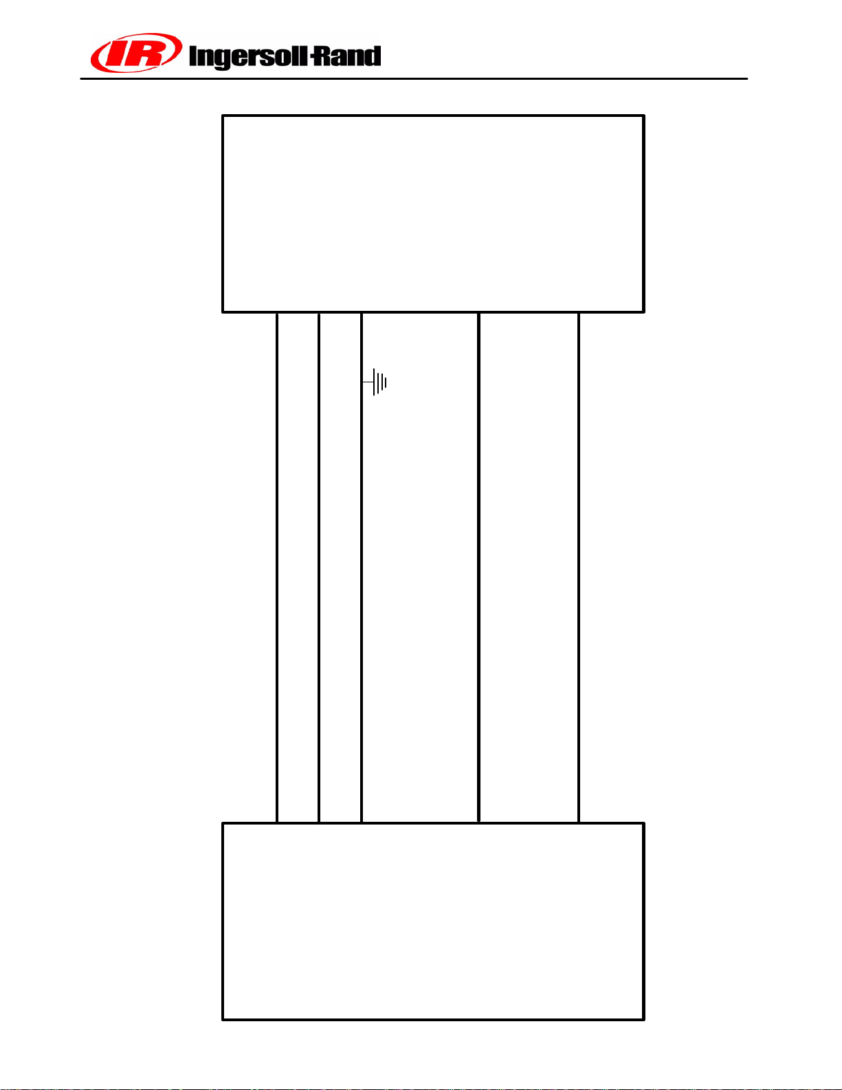
WEDGE TO ENGINE INTERFACE
IR ENGINE
CAN LO
J50--G1
CAN HI
CANSHLD
J50--J1
IR
41RD5AE
KEY SWITCH
J50--A2
61IRF8TE
ENGINE
ANALOG THROTTLE
ANALOG THROTTLE RANGE = 1.10VDC (1400RPM) TO 3.7VDC (2400 RPM)
J50--F2
FIGURE 2--2
Book No. 22235428 (11/03)
6()
CONTROLLER
P425AWIR Family Electrical Manual
Page 8
WEDGE
CONTROLLER
P6
R5
R4
ENGINE DIAGNOSTICS JACK
J57
TERMINATOR
TERMINATOR
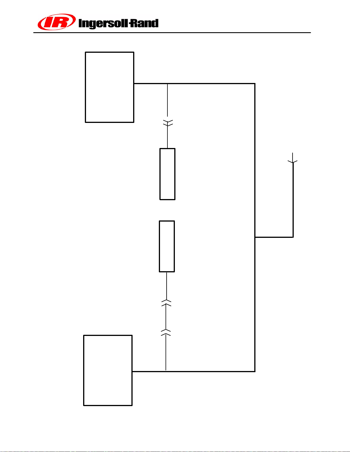
P425/P600 J1939 CAN COMMUNICATIONS SCHEMATIC
ENGINE ECM
Book No. 22235428 (11/03)
P1 1
P10
7()
FIGURE 2--3
P425AWIR Family Electrical Manual
Page 9

The wedge uses an analog signal to communicate
withtheJohnDeere engine.Thissignalhasa range of
1.1V to 3.7V. This range corresponds to an engine
speed range of 1400 to 2400 RPM.
Figure 2--2 shows the signals between the engine
controller and the WEDGE controller.
Sensors and Transducers
The electronics system contains sensors and transducersthatareusedtocollectdata from the compressor. The temperature is measured by a thermistor.
Thisdeviceexhibitsa changeinresistanceasthetemperature changes. The resistance causes an input
voltage change to the WEDGE controller input and is
interpreted as a temperature change.
The electronics system also uses pressure transducerstomeasurecompressorpressurechanges. These
devices have an output signal of .45 VDC to 4.5 VDC,
corresponding to 0 psi and the maximum measured
psi for a particular device. The maximum pressure
transducer ranges are 100 or 225 psi. The 100 and
225 psi devices are gauge pressure devices. These
transducers are provided with 5 VDC excitation to
power the device. These are three wire devices: excitation, signal and ground.
Digital Inputs and Outputs
The WEDGE controller scans digital inputs such as
switch contacts. These are either “ON” (24VDC) or
“OFF” (0 VDC). These digital inputs are connected to
switches within the package such as the key start
switch, air filter switches and IQ filter switches.
The WEDGE controller provides 24 VDC digital
outputsto control solenoids,start compressor andDC
heaters. These are 24 VDC “ON” and 0 VDC “OFF”.
They are current limited and short circuit protected.
TheWEDGEvariestheanalogsignalfrom1.25to4.25
volts,correspondingto1400 to2100RPM. Thissignal
is used with the John Deere engine. The frequency
throttle signal is used with the Cummins engine and
thepulsewidth modulated signal is used with the CAT
engine.
Pressure Control
The discharge pressure is controlled by manipulating
theengine speed andcompressor inlet valveposition.
Theinletvalvepositioniscontrolledpneumaticallyand
the engine speed is determined by the WEDGE controller.The WEDGE measures the pneumatic system
regulation pressure and computes an engine throttle
setting.Thisthrottle settingissent totheengineviathe
frequencythrottle, Analog,PWM or J1939throttle, depending on which technique is used. The engine controller will control engine speed to this throttle setting.
Electronic Engine -- P425 Family of Machines
The P425 Family of machines contains an emissions
certifieddiesel engine. Inordertomeet the emissions
requirements, the engine has an electronic control
system.
The control system handles all monitor, alarm and
controlfunctions for the engine. The WEDGEcontroller communicates with the engine controller over the
J1939 CAN network.
The WEDGE controller sends throttle settings to the
engineandreceivesdiagnosticandruntimedatafrom
the engine over the J1939 CAN network. An analog
throttle interface is currently used with the engine.
Figure 2--2 shows the connections between the
WEDGE controller and the engine controller.
Controller Outputs
The WEDGE controller has four types of outputs: frequency, pulse width modulated, analog and 24VDC
digital (ON/OFF). The analog output is used as the
throttle signal to the engine.
Book No. 22235428 (11/03)
8()
P425AWIR Family Electrical Manual
Page 10

J1939 Data Link
The CAN network is a single pair shielded cable
located with the W1 main harness. Figure 2--3 shows
a layout of the CAN harness or “backbone” as it is
referredto. The termination resistors(Terminator)are
important to prevent reflections on the transmission
line and must be in place for the network to function
properly.
Theenginediagnostics connectorislocatedonthe left
side of the engine. This is used to connect the engine
manufacturer’sservicetoolstotheCANnetwork. This
connector also provides 24 VDC to power these
service tools.
Electrical System
Theelectrical systemconsists of thewiring harnesses
and associated electrical devices such as relays,
switches, lights, solenoids and alarm horn. There is
one wiring harnesses in the P425 machine.
The electrical circuits are protected using ATC style
fuses. A fuse should only be replaced with one of the
same rating. Replacing a fuse with one of a large
rating could lead to harness damage. If a fault occurs
andthecircuitdoes nothavetheappropriatesizefuse,
wires could be burned in the harness and damage
other circuits.
Machine ID
Software versions 1.60 and greater use software to
setthe machine ID. Versionsless than 1.60usean ID
resistor plug, R2. The ID plug is located behind the
control panel box on the W1 harness trunk. The
resistor plugs are molded in colors for easy
identification. Refer to Section 7, Individual Circuit
Diagrams and the page entitled R @ MACHINE ID
PLUG for details.
It is recommended that all machines be upgraded to
Version1.60orgreater.Thesoftware setmachineIDis
much more reliable than the resistor plug.
P/N 22199061 W1 Chassis Main Harness
Theschematicdiagramsshow theconnectionsfor this
harness. Figure 2--1 is a system schematic showing
harnessconnectionwithdevicesandcontrollers. Section 8 includes information on connectors used in the
harness.
Book No. 22235428 (11/03)
9()
P425AWIR Family Electrical Manual
Page 11

PT1:
PT2:
U1:
RT1:
RT2:
K1:
KEY ELECTRICAL COMPONENTS FUNCTION
PT1 is a 0--225 psi gauge pressure transducer that measures discharge air pressure.
PT2 is a 0--100 psi gauge pressure transducer that measures regulation system pressure.
U1 is resistive level detector that measures the fuel level in the fuel tank.
Itprovidesa continuous reading of fuel level. Italso has a switch for low fuellevel andlow fuelshutdown.
These switches connect to WEDGE.
RT1 is a 10K ohm Thermistor temperature sensor that measures separator tank temperature.
Its range is --30 to 255_ F.
RT2 is a 10K ohm Thermistor temperature sensor that measures airend discharge temperature.
Its range is --30 to 255_F.
K1 is SPST, 24VDC relay used to activate the engine starter.
K2:
K2 is a SPST, 24VDC relay used to activate the engine inlet heater.
Book No. 22235428 (11/03)
10()
P425AWIR Family Electrical Manual
Page 12

CONTROL PANEL
DIAGNOSTIC SHUTDOWN (Standard)
1. Compressor Fault: Indicates shutdown due
to compressor system fault. Refer to fault
code list in Section 10.
2. Engine Fault: Indicates shutdown due to
engine fault. Refer to fault code list in Section
10.
3. Hourmeter: Indicates machine operating
hours.
4. Discharge Air Pressure Gage: Indicates
pressure in receiver tank, psi (kPa).
5. Fuel Level Gage: Indicate fuel level in tank.
CONTROLS
6. PowerSwitch: Flip“ON” to activate systems
7. Service Air Switch: After warm--up, PUSH.
Book No. 22235428 (11/03)
(Standard)
prior to starting. Flip ’off” to stop engine.
Providesfull air pressure atthe service outlet.
OPTIONAL CONTROLS
8. Engine Speed Gauge: Indicates engine
speed.
9. DischargeAirTemp.Gauge: Indicatesin_F
and _C. Normal operating range:
185_F/85_C to 248_F/120_C.
10. Engine Oil Pressure Gauge: Indicates
engine oil pressure psi (kPa).
11. Engine Water Temp Gauge: Indicates
coolant temperature with normal operating
range from 180_F/82_C to 210_F/99_C.
12. Voltmeter: Indicates battery condition.
13. Spare
14. Wait to Start Lamp
11()
P425AWIR Family Electrical Manual
Page 13

OPERATIONAL INFORMATION
Power “ON” at Control Panel:
1. Key switch signal (24VDC) supplied to engine controller by WEDGE controller
Engine Start--up:
When the key is switched to the engine crank position:
1. K1 auxiliary start relay is energized.
2. Run/Start solenoid valve (L1) is opened (energized).
Note: Run/start solenoid stays open for 10 seconds after the key is released if the engine does not start.
When the engine speed reaches 600 RPM (engine start declared):
1. Engine speed is set to 1600 RPM.
When the engine speed reaches 1450 RPM:
1. Unloader solenoid valve is opened (energized), L2.
2. Run/Start solenoid valve is closed (de--energized, L1).
When the separator tank pressure reaches 50 psi:
1. Run/Start solenoid valve is opened (energized), L1.
After 5 seconds:
1. Engine speed is set to idle (1400 RPM if air end discharge temperature is approximately
150 degrees F or (if J1939 CAN is functioning) the engine coolant is 100 degrees F.
Otherwise, the engine idle stays at 1500 RPM.
Loading:
When the “Service Air” s witch is pushed:
1. Engine speed is set to 2400 RPM
When engine speed reaches 2200 RPM:
1. Run/Start solenoid valve is closed (de--energized).
After 2 seconds and if the regulation system pressure is 4 psi or greater:
1. Compressor pressure control is engaged.
Book No. 22235428 (11/03)
12()
P425AWIR Family Electrical Manual
Page 14

READING AND SETTING THE DISPLAY
UNITS
The WEDGE has four choices for display units:
_F, PSI
_C, Bars
_C, kPa
_C, Kg/cm2
To determine which units the WEDGE has been configured for:
1. With the machine power off (Key turned OFF)
2. Press and hold the “Service Air” Switch
3. Turn the key switch directly to the crank position.
4. Hold these switch positions until the 4 digit LED display on the WEDGE goes blank.
5. Release “Service Air” switch, release key switch to “ON”.
Units will be displayed for 2 s econds after which the current selection will be displayed as:
_F, PSI will be displayed as “PSI”
_C, Bars will be displayed as “bAr”
_C, kPa will be displayed as “HPA”
_C, Kg/cm2 will be displayed as “H9C”
To change the units setting:
1.With theWEDGE showingthe currentsetting, pressandrelease the“Service Air”switch untilthedesired setting
appears on the display.
2. Once it appears, do not release the “Service Air” switch. Hold it in the ON position until the WEDGE restarts.
This will select units selection that was displayed.
3. Release the “Service Air” switch. The compressor is ready to start.
Book No. 22235428 (11/03)
13()
P425AWIR Family Electrical Manual
Page 15

WEDGE SERVICE DIAGNOSTICS
The WEDGE controller provides a diagnostic capability that allows various internal parameters to be viewed on
the 4--digit LED display.These can be accessed with the machine stopped or while it is operating. If the machine
is stopped, the “Service Air” switch on the control panel is used to toggle through the list of parameters. If the machine is operating, the “Start” position of the key switch is used. Toview the parameters, toggle the switch or key
and a number (2--20) will appear on the LED display. After 3 seconds, it will extinguish and the parameter will be
displayed. The toggle only works in the ascending order direction, but it will wrap around and start over.
Display Parameter Remarks
2 RPM From Engine Flywheel Sensor
3 Engine RPM Filtered RPM Value
4 Reg. Sys. Pressure PSI
5 Sep. Tank Pressure PSI
6 Discharge Temperature Deg F
7 Sep. Tank Temperature Deg F
8 Engine Target RPM Wedge Signal to Engine
9 Machine Type *
10 Engine Coolant Temp. From CAN, Deg F
11 Engine Oil Temp. From CAN, Deg F
12 Engine Oil Pressure From CAN, PSI
13 Intake Manifold Temp. From CAN, Deg F
14 RPM From CAN
15 Fault Code List Cummins/CAT codes
16 Throttle Position
17 Boost Pressure
18 Engine Hours
19 Load At Speed Percent
20 Set Machine ID
Book No. 22235428 (11/03)
14()
P425AWIR Family Electrical Manual
Page 16

ENTERING MACHINE ID FOR WEDGE CONTROL SYSTEMS with V1.60 or Greater Software
For machines with the WEDGE controller mounted inside the control panel/instrument panel box, the “Service
Air” switch is used to enter the machine ID. Disconnect the fuel level gauge (located in the fuel tank) before
starting the process and reconnect once the process is completed.
For machines with the WEDGE controller mounted in the engine compartment, the rocker switch beside the
WEDGE is used to enter the machine ID.
For the instructions below, the “Service Air” or rocker switch will be referred to as the “data input switch”.
1. Examine the machine data plate to confirm the machine model.
Using the machine model and the machine models list on page 2 of this document, locate the proper
machine ID.
2. Turn power to the ”ON” position. Machine must not be operating.
3. Toggle the data input switch twice and the number “2” will appear on the WEDGE 4--digit LED display.
Continue to toggle the switch until the number “9” is reached. Read the machine ID on the
display, if it matches the proper machine ID in Step 1, stop. If not, proceed to step 4.
4. Continue to toggle the switch until number “19” is reached. Push and hold the data input switch and the
number“20” willappear.Continue toholdthe switch.After 1second,the currentmachine IDwillappear in
the display. Continue to hold for 9 more seconds and a blinking “--” will appear. Release the switch.
5. Togglethedatainputswitch, thedisplaywillshow“0”.Togglethedata inputswitchuntiltheproper machine
ID appears on the display, then stop the toggle sequence.
6. Waituntil the controller performs a reset function (or power up) (approximately 10 seconds). At reset, the
controllerdisplayfirstgoesblank,thenal110annunciato rLED’slight,the4--digitLEDdisplayshowsall8’s,
thedisplay then shows the installed software version and finally the display goes blank and the engine oil
pressureand alternatorLED begin flashing.At thispoint thecontrollerhas storedthemachine IDselected
in step 5.
7. Using the data input switch, toggle to service diagnostic number “9”.
The number “9” will appear for 1 second and then the machine ID will appear. The ID should be the same
as the one entered in steps 4--6. If not, go back to step 4 and enter the ID again.
Book No. 22235428 (11/03)
15()
P425AWIR Family Electrical Manual
Page 17

ESA Models/Wedge Machine
ID
Models
7/120,9/110. 10/105, 14/85 7
7/170. 10/125.14/115 8
9/230,9/270,9/300. 12/235 5
17/235,21/215 6
MSA Models/Wedge Machine
ID
Models
P425AWIR, XP375AWIR, HP375WIR 7
VHP300AWIR
P600WIR, HP450WIR, VHP400WIR 8
XP1060WCU, HP935WCU, MHP825WCU 5
VHP750WCU
XHP750WCU 6
MHP825WCAT, VHP750WCAT 2
XP1060HACAT,XP950HACAT
SHP825WCAT, XHP750WCAT. XHP650WCAT 3
HP1300CWCU,HP1600CWCU 0
XHP1170WCU 1
XHP1070AWCAT, XHP1170WCAT. XHP1170SCAT 4
HP1600WCAT 9
Machine ID
Machine ID
SIRC Models/Wedge Machine
ID
Models
P1060WCAT, XP950WCAT, HP935WCAT 2
MHP825WCAT .VHP750WCAT
XHP750WCAT 3
Book No. 22235428 (11/03)
16()
Machine ID
P425AWIR Family Electrical Manual
Page 18

SECTION 3
SERVICE TOOLS
Book No. 22235428 (11/03)
17()
P425AWIR Family Electrical Manual
Page 19

SERVICE TOOLS
Service Tools
The following special tools are recommended to perform service procedures in this manual. The tools can
be purchased from Ingersoll Rand or other sources as listed.
Tool Tool Description
22216691 Digital Multimeter (Fluke 87)
Used to measure electrical circuits; Volts, amps, ohms
54729660 Packard Weather--Pack Terminal Removal Tool
Used to repair Packard Electric Weather--Pack Connectors
54699632 Deutsch Terminal Removal Tool (Blue)
Used to repair Deutsch connectors
54699640 Deutsch Terminal Removal Tool (Red)
Used to repair Deutsch connectors
54699624 Deutsch Terminal Removal Tool (Yellow)\
Used to repair Deutsch connectors
22216667 Deutsch Terminal Crimp Tool (HDT--48--00)
Used to crimp Deutsch connector terminals
54729710 Electrical Contact Cleaner
Used to clean electrical contacts and connectors
54729728 PDA Service Tool
Used to load software & extract service and fault logs
54699616 Deutsch Terminal Removal Tool
Used to repair Deutsch connectors
54749544 RTD Simulator Plug
Used to test RTD circuits
54749551 Thermistor Simulator Plug
Used to test thermistor circuits for INTELLISYS controller systems
22073878 Thermistor Simulator Plug
Used to test thermistor circuits for WEDGE controller systems
54749635 Connector Repair Kit
Used to make connector repairs for Deutsch and Packard Electric Connectors
54699657 Deutsch Terminal removal Tool
Used to repair Deutsch connectors
54749643 Packard Metri--Pack Terminal Removal Tool
Used to repair Packard Electric connectors
Book No. 22235428 (11/03)
18()
P425AWIR Family Electrical Manual
Page 20

22168868 Pressure Transducer Simulator
Used to test pressure transducer circuits
22147540 Test Adapter Kit Test adapters for various connectors to be
Used when making electrical measurements
22146393 Removal Tool Kit Assortment of most used Deutsch removal tools
22216675 Deutsch Crimp Tool (DTT --20--00)
Used to crimp Deutsch connector terminals
22216683 Packard Electric Crimp Tool (12155975)
Crimps 150 and 280 series pins
22255947 Packard Electric Crimp Tool (12039500)
Crimps 150 series pull to seat pins
22216709 Fluke Test Lead Set (TL20)
Contains needle probes, alligator clips, test leads
heat shrink tubing that are used on harnesses
22216725 Fluke Insulation Piercing Probe (AC--89)
Used to connect to a wire for measurements
22216733 Fluke Meter Case (C25)
Case for Fluke 87 meter including storage for test leads and probes
54740675 RS232 Heavy Duty Serial Cable
Connects lap top computer or PDA Service Tool
to WEDGE or Intellisys controller
22252969 Wire Terminal Kit
Contains a selection of terminals with
corresponding heat shrink tubing that are used on harnesses
22281588 Connector Wrench
22282107 5/32 “T” hex screwdriver wrench
22282172 1/4” Flex Shaft Nutdriver
Used to remove ECM connector on J ohn Deere engines
22252993 WEDGE Connector Kit
Includes the 40--pin connector housing and pins for the harness connector
22253009 CAN Communications Adapter
Converts RS232 to J1939 CAN, used with lap top computer
or PDA Service T 001
22253017 Adhesive Heat Shrink Assortment
Selection of most used heat shrink sizes
Book No. 22235428 (11/03)
19()
P425AWIR Family Electrical Manual
Page 21

22221303 Service Tool Kit
Kit consists of the following P/N’s: 22216691 22216667
22216675 22216683 54729660 54749643 54699657
22146393 22147540 22073878 54749635 22168868
22216709 22216725 22216733 54740675
22254775 ATC Fuse Assorlment Kit
Kit contains 5, 7--1/2, 10, 15,20,25, and 30 Amp fuses
22254734 Packard Crimp Tool (12014254) Crimps Sealed
Weather Pack Connector pins
Book No. 22235428 (11/03)
20()
P425AWIR Family Electrical Manual
Page 22
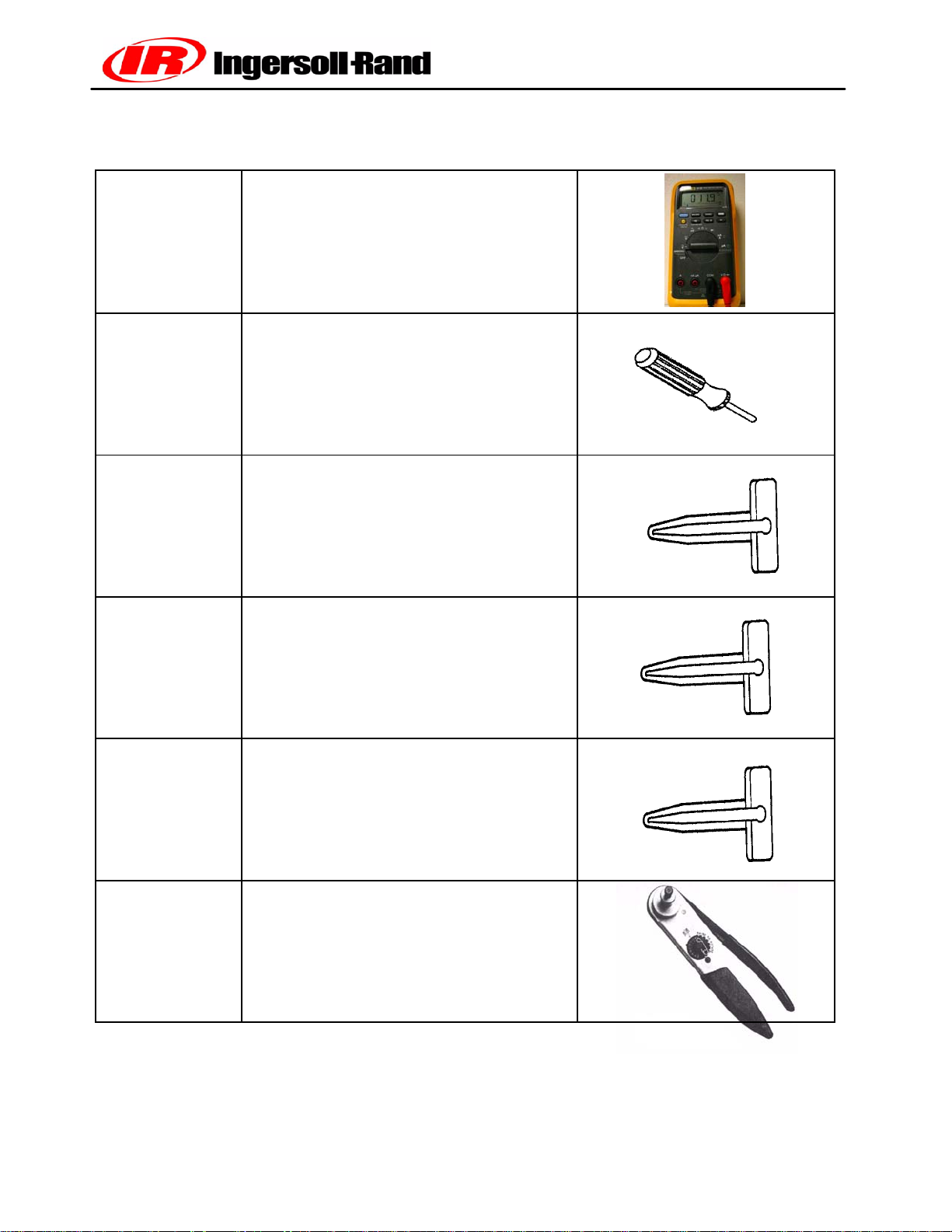
Tool No. Tool Description Tool Illustration
22216691
54729660 Weather--Pack Terminal Removal Tool
54699632 Deutsch Terminal Removal Tool (Blue)
54699640 Deutsch Terminal Removal Tool (Red)
Digital Multimeter
54699624 Deutsch Terminal Removal Tool (Yellow)
22216667 Deutsch Crimp Tool
Book No. 22235428 (11/03)
21()
P425AWIR Family Electrical Manual
Page 23

54729710
54729728 PDA Service Tool
54699616 Deutsch Terminal Removal Tool
54749544 RTD Simulator Plug
Electrical Contact Cleaner
22073878 Thermistor Plug
54749635 Connector Repair kit
54699657 Deutsch Terminal Removal Tool
Book No. 22235428 (11/03)
22()
P425AWIR Family Electrical Manual
Page 24
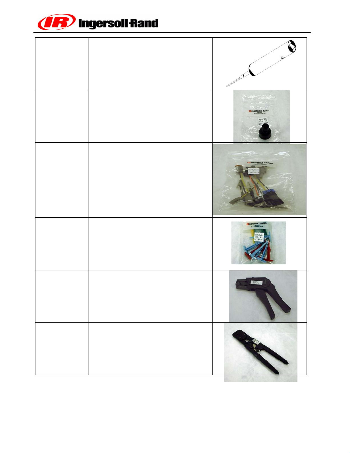
54749643
Packard Metri--Pack Removal Tool
22168868 Pressure Transducer Simulator
22147540 Test Adapter Kit
22146393 Removal Tool Kit
22216675 Deutsch Crimp Tool
22216683 Packard Electric Crimp Tool
Book No. 22235428 (11/03)
23()
P425AWIR Family Electrical Manual
Page 25
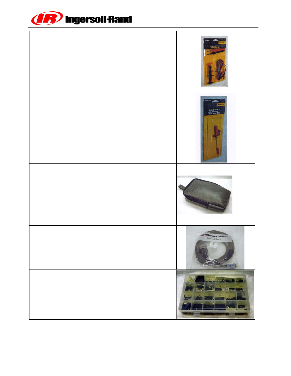
22216709
Fluke Test Lead Set
22216725 Fluke Insulation Piercing Probe
(single probe)
22216733 Fluke Meter Case
54740675 RS232 Serial Cable
22253969 Wire Terminal Kit
Book No. 22235428 (11/03)
24()
P425AWIR Family Electrical Manual
Page 26
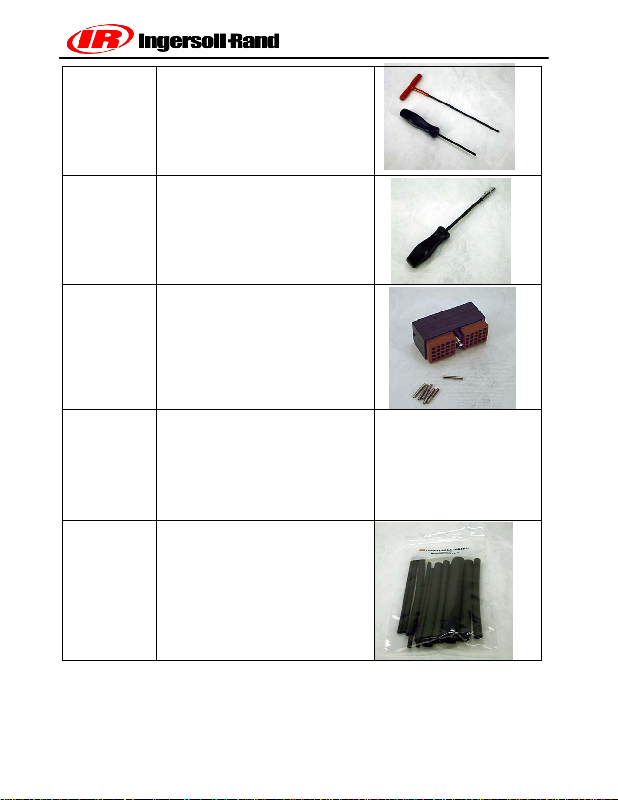
Connector Wrenches
22281588
22282172
22282172 1/4’’ Flex Shaft Nutdriver
22252993 WEDGE Connector Kit
22253009 CAN Communications Adapter
22253017 Adhesive Heat Shrink Assortment
Book No. 22235428 (11/03)
25()
P425AWIR Family Electrical Manual
Page 27
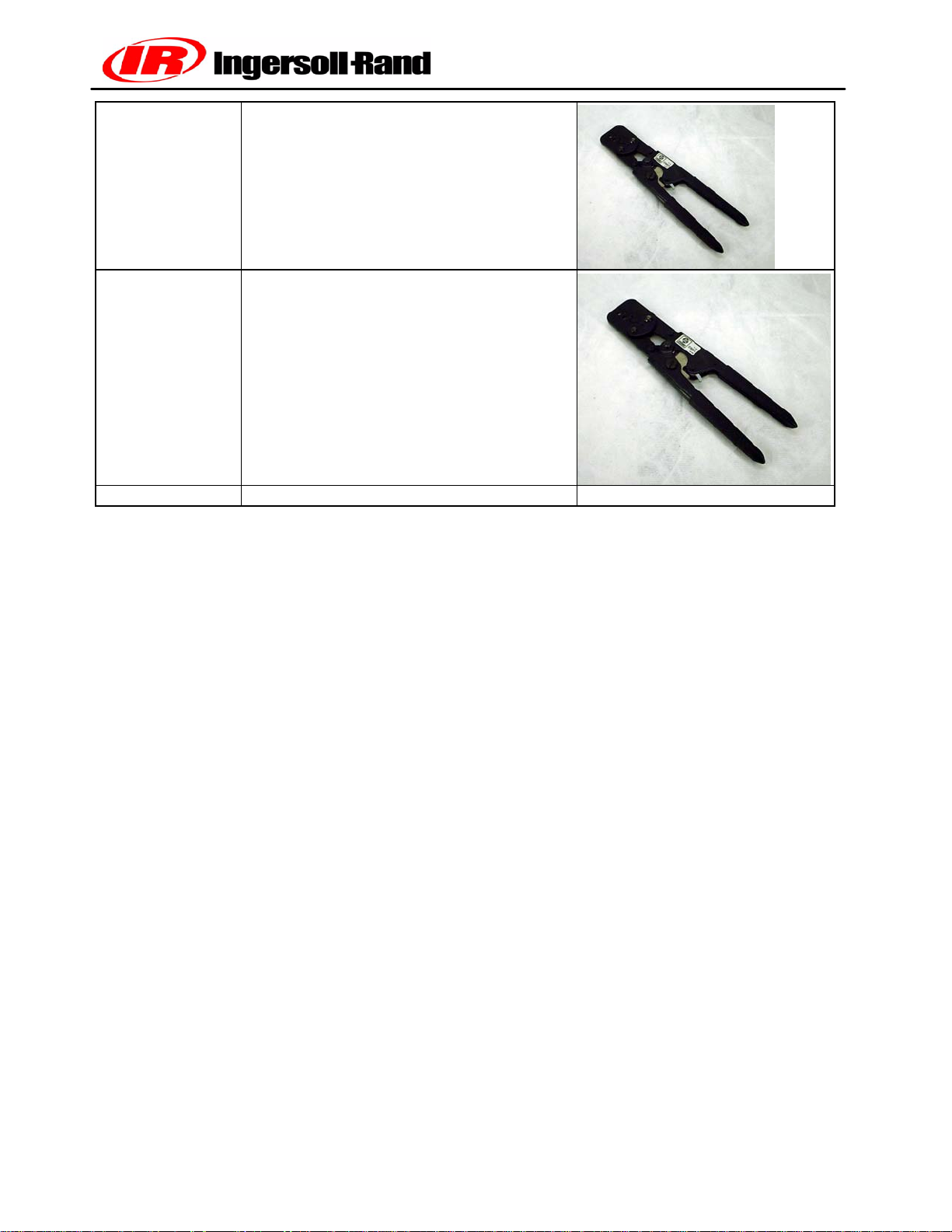
22255947
22254734 Packard Electric Crimp Tool
Packard Electric Crimp Tool
Book No. 22235428 (11/03)
26()
P425AWIR Family Electrical Manual
Page 28

SECTION 4
ELECTRONIC SYSTEMS TROUBLESHOOTING
PROCEDURES AND TECHNIQUES
Book No. 22235428 (11/03)
27()
P425AWIR Family Electrical Manual
Page 29

General
A thorough analysis of the problem is the key to successful troubleshooting. The more information known
about a problem, the faster and easier the problem can be solved.
Troubleshooting charts are included to act as a guide to the troubleshooting process. They are organized so
the easiest and most logical things are performed first. It is not possible to include all the solutions to problems
that can occur or list all possible problems. The charts are designed to stimulate a thinking process that will
lead to solution of the problem.
Basic Troubleshooting Steps
• Collect all facts concerning the problem
• Analyze the problem thoroughly
• Relate the symptoms to the basic electrical / electronic systems and components
• Consider any recent repairs that could relate to the problem
• Double check before replacing components
• Review the controller fault log for clues as to the problem
• Determine the cause of the problem and make a thorough repair
Book No. 22235428 (11/03)
28()
P425AWIR Family Electrical Manual
Page 30

MEASURING VOLTAGE, RESISTANCE,
FREQUENCY AND DUTY CYCLE
General Measuring Guidlines:
Since the electrical system uses sealed connectors and splices, access of test points can be difficult. It is recommended that a test probe kit be used to access the signals to prevent damage to wires and connectors.
Back probing connectors and insulation piercing test probes can cause damage that can cause future failures.
Measuring Voltage:
A digital voltmeter is recommended to make measurements. Voltage measurements are made by connecting
the RED + lead to the desired signal and the BLACK lead to the common. The test lead connections must be
secure or incorrect readings will result. Use circuit common for the Black lead, not chassis ground or other
metal connection. Circuit common will be any of the BROWN wires or battery negative can be used.
IMPORTANT INFORMATION
DO NOT USE MACHINE FRAME, SHEET METAL, PIPING OR OTHER METAL COMPONENTS AS COMMON OR GROUND WHEN MAKING VOLTAGE OR FREQUENCY
MEASUREMENTS.
Measuring Resistance:
Extra care must be taken when making resistance measurements. Testprobe connections are crucial to correct readings. Ensure the test probe makes a solid connection with the wire(s) or connector pin(s) under test.
the test probe kit may help with these types of measurements. Make sure system power is turned OFF while
making resistance measurements.
Measuring Frequency:
Frequency is measured in the same manner as voltage, but the meter is set for “HZ” or frequency. Good connections are important or false readings will occur.
Measuring Duty Cycle:
To measure duty cycle, setup the meter as if measuring frequency or voltage. Select the “%” or duty cycle
function and take the measurements. As of the date of this writing, Fluke is the only known digital voltmeter
that has the duty cycle feature. The Fluke Model 87 Digital Meter has the duty cycle function.
Book No. 22235428 (11/03)
29()
P425AWIR Family Electrical Manual
Page 31
TROUBLE SHOOTING FLOW CHART
Control panel key is turned to “ON” position,
WEDGE controller annunciator lamps and 4
digit LED display do not come on
B
WEDGE controller annunciator lamps & 4
digit LED display initialize OK but alternator
lamp and engine oil pressure lamps do not
blink.
B
Engine cranks but will not start
Check F1 fuse
Check operation of switch S1
Check wiring from S1 to WEDGE controller
Check battery voltage, ensure battery disconnect switch is turned ON
J1939 CAN communications not working –
Check for 24VDC key switch at engine, CAN
network wiring problem
Ensure 24VDC power to engine ECM
Check connector pins
Ensure key switch (24VDC) at engine
Frozen fuel cooler or associated piping
Estop button pressed (ESA units) or
Estop jumpers not making connection
Clear active engine fault code
B
Engine does not crank when key turned to
crank position
B
Compressor fails to load
when “Service Air” switch pressed
Book No. 22235428 (11/03)
Check switch S1
Check relay K1
Check starter solenoid
Check starter motor
Check WEDGE output to K1 relay
Check battery voltage
Check Run/Start valve operation
Verify frequency throttle signal at engine
Check “Service Air” switch operation
30()
P425AWIR Family Electrical Manual
Page 32

COMPRESSOR FAULT CODES
DESCRIPTION AND TROUBLESHOOTING
Following, are the descriptions of the COMPRESSOR fault codes. These are indicated when the
“COMPERSSOR MALFUNCTION” lamp is illuminated. The compressor malfunction lamp is
shown on the control panel picture in Section 2 of this manual. It is indicated by Item number 9.
The engine fault codes are indicated by the “ENGINE MALFUNCTION” lamp that is located under
the “COMPRESSOR MALFUNCTION” lamp.
The engine fault codes are listed in Section 10 of this manual.
Be sure to determine which malfunction lamp is illuminated before beginning the troubleshooting
process.
31
Page 33
COMPRESSOR CODE 1
Engine Speed Less Than 800 RPM
Explanation:
The WEDGE has received an engine speed less than 800 RPM for 30 seconds.
Effect:
Code 1 is a shutdown condition and will shutdown the machine.
TROUBLESHOOTING STEPS
Code 1
Action Result
Check engine fault codes for an engine
shutdown. Check for engine fuel system
restriction (filter).
32
Page 34
COMPRESSOR CODE 2
Engine Speed Greater Than 1900 RPM
Explanation:
The WEDGE has received an engine speed greater than 1900 RPM for 30
seconds.
Effect:
Code 2 is a shutdown condition and will shutdown the machine.
TROUBLESHOOTING STEPS
Code 2
Action Result
Check engine fault codes for an engine
shutdown.
33
Page 35
COMPRESSOR CODE 3
Engine Crank Time Exceeded
Explanation:
The engine crank time has exceeded 15 seconds.
Effect:
Code 3 is a shutdown condition and will shutdown the machine.
TROUBLESHOOTING STEPS
Code 3
Action Result
Crank engine for less than 15 seconds.
34
Page 36
COMPRESSOR CODE 5
Engine Oil Temperature
Explanation:
The WEDGE has received an engine oil temperature greater than 252 Deg F
Effect:
Code 5 is an ALERT condition and will not halt machine operation.
TROUBLESHOOTING STEPS
Code 5
Action
Step1:
Refer to the engine manufacturer’s service manual for
instructions.
Result
35
Page 37
COMPRESSOR CODE 6
Engine Intake Manifold Temperature
Explanation:
The WEDGE has received an engine intake manifold temperature greater than
180 deg F.
Effect:
Code 6 is an ALERT condition and will not halt machine operation.
TROUBLESHOOTING STEPS
Code 6
Action
Step1:
Refer to the engine manufacturer’s service manual for
instructions.
Result
36
Page 38
COMPRESSOR CODE 8
Water in Fuel
Explanation:
The WEDGE has received a water in fuel indication from the engine.
Effect:
Code 8 is an ALERT condition and will not halt machine operation.
TROUBLESHOOTING STEPS
Code 8
Action
Step1:
Check the machine fuel system and engine fuel filters.
Step 2:
Refer to the engine manufacturer’s service manual for
instructions.
Result
37
Page 39
COMPRESSOR CODE 10
Engine Not Responding To Throttle Command
Explanation:
The engine has not responded to a request from the WEDGE for engine speed
change during engine start. This ALERT will only occur during the idle speed
time, right after engine start.
Effect:
Code 10 is an ALERT condition and will not shutdown the machine. The
machine will not perform properly due to the low speed condition.
Throttle Circuits:
C
M
U
M
NS
I
E
N
G
I
E
C
N
O
N
T
RO
L
L
E
R
J3-22 J1-38
W131
Freq Throttle
Blu
WEDGE
CONTROLLER
C
A
T
E
N
I
G
N
C
O
E
N
T
R
O
L
L
E
R
J2-10 J1-38
W131
PWM
Throttle
Blu
WEDGE
CONTROLLER
R
I
E
N
I
G
E
N
C
O
N
T
R
O
L
L
R
E
J50-F2 J1-13
W054
Analog
Throttle
Blu
WEDGE
CONTROLLER
38
Page 40

Circuit Description:
As shown in the circuits above, the WEDGE provides three types of throttle
outputs: frequency, PWM and analog.
TROUBLESHOOTING STEPS
Code 10
Action
Step1:
Measure the throttle signal at the engine connector.
Result
If signal not present, check wiring
and verify throttle output at
WEDGE.
Step 2:
Engine may not be able to fuel properly due to restricted fuel
filters
Step 3:
Verify correct machine ID plug is installed. If so, verify
resistance value of ID plug and its connection to WEDGE
controller.
Step 4:
Check connector pins at WEDGE controller and connector at
engine controller for corrosion.
Replace fuel filter (s)
39
Page 41
COMPRESSOR CODE 11
Too Many Start Attempts During Auto Start
Explanation:
The WEDGE has made three attempts to start the machine as commanded by
the Auto Start Stop controller. The machine failed to start.
Effect:
Code 11 is a SHUTDOWN condition and will shutdown the machine.
TROUBLESHOOTING STEPS
Code 11
Action
Step1:
Check the machine fuel system and engine fuel filters.
Step 2:
Check the condition of the machine batteries.
Step 3:
Cycle machine power, activate the Auto Start input so the
machine will make another start attempt. Machine will go
through 3 crank cycles to attempt start before a Code 11 is
issued.
Result
40
Page 42
COMPRESSOR CODE 29
Engine shut itself down: reason unknown
Explanation:
The engine has shut down. The WEDGE did not shut down the engine.
Effect:
Code 29 is a SHUTDOWN condition and will shutdown the machine.
TROUBLESHOOTING STEPS
Code 29
Action
Step1:
Check the machine fuel system and engine fuel filters. Check
for loose fittings in the fuel piping that could allow air to be
drawn into the fuel system.
Step 2:
Verify the throttle signal from the WEDGE is continuously
supplied to the engine.
Step 3:
Verify battery + and – connections to the engine controller,
inspect harness connections and measure voltage drop at
engine ECM.
Step 4:
In the case of the I-R (John Deere) engine, check the
connections for the crank sensor which is mounted at the front
of the engine. Loose pin connections in the connector will
cause code 29.
Result
A quick drop in the throttle signal
could cause the engine to stop
41
Page 43
COMPRESSOR CODE 31
Low Air End Oil Pressure (HP1600 Only)
Explanation:
The WEDGE received a closed contact from pressure switch S9, located
in the air end on the HP1600 machine. This indicates a low oil pressure in the
air end.
Effect:
Code 31 is a shutdown condition and will shutdown the machine. The
cause of the low air end oil pressure must be repaired to continue machine
operation.
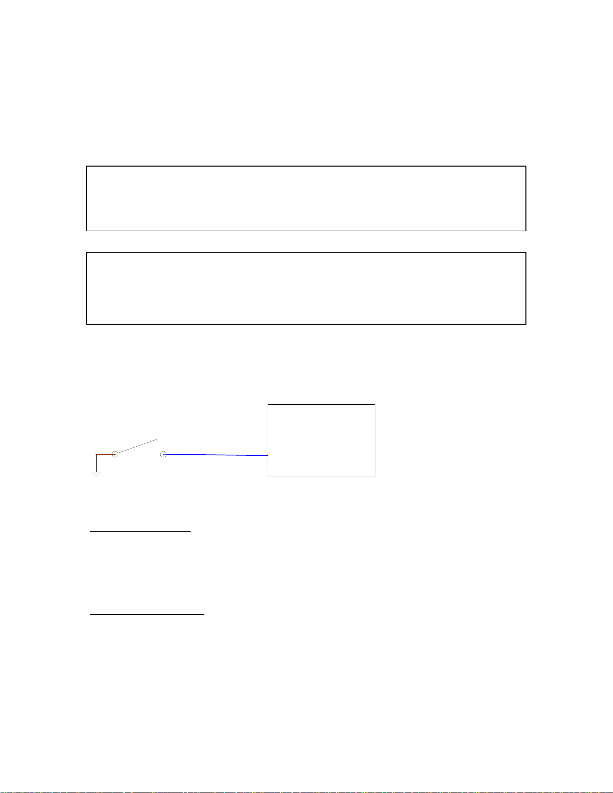
S9 Pressure Switch Circuit:
S9
Blu
J1-21
WEDGE
CONTROLLER
Circuit Description:
Switch S9 is a 12 psi, normally open pressure switch. If the pressure falls below
12 psi, the switch will close, indicating to the WEDGE controller a low air end oil
pressure.
Component Location:
S9 is located in the back of the air end.
42
Page 44

TROUBLESHOOTING STEPS
Code 31
Action
Step1:
Check the air end oil pressure with a mechanical gauge.
Result
If > 12 psi, replace S9
If not, there is a harness or
WEDGE problem.
43
Page 45
COMPRESSOR CODE 32
RT2, Discharge Temperature Sensor Fault
Explanation:
The WEDGE has received an out of limits reading from the RT2 temperature
sensor. This reading could be on the high or low end of the range. It is
out of the normal range for temperature measurement.
Effect:
Code 32 is a shutdown condition and will shutdown the machine.
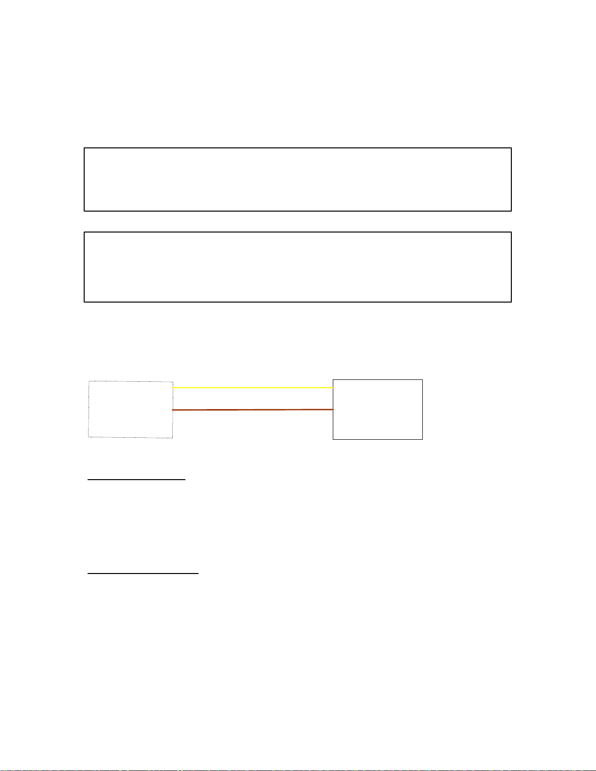
RT2 Temperature Sensor Circuit:
1
W066
Yel
J1-5
R
T
2
T
m
e
p
r
e
t
a
u
e
r
S
n
e
s
r
o
W025
2
Brn
J1-6
WEDGE
CONTROLLER
Circuit Description:
The thermistor temperature sensor connects to the WEDGE controller as shown
in the schematic above. The temperature range of RT2 is –30 to 255 degrees F.
The thermistor is a 10K ohm device.
Component Location:
RT2 thermistor is located in the airend discharge pipe.
44
Page 46

TROUBLESHOOTING STEPS
Code 32
Action
Step1:
Substitute the thermistor simulator (I-R # 22073878) for RT2
Use the WEDGE service diagnostics to read the value for RT2
It should be approximately 32 degrees F.
Result
Should read approx. 32 Deg F
If not, there is a harness or
WEDGE problem.
45
Page 47
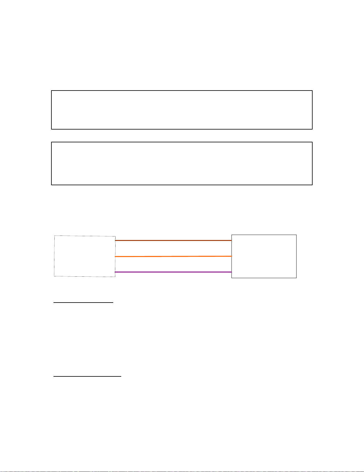
COMPRESSOR CODE 33
PT1 Pressure Transducer Sensor Fault
Explanation:
The WEDGE has received an out of limits reading from the PT1 pressure
transducer. This reading could be on the high or low end of the range. It is
out of the normal range for pressure.
Effect:
Code 33 is an ALERT condition and will not shutdown the machine. If the
Transducer is defective, the machine could shutdown due to an out of
range pressure
PT1Pressure Transducer Circuit:
A
W099
Gnd
Brn
J1-8
P
T
1
P
r
e
s
s
u
r
T
e
r
a
n
s
d
u
c
e
r
C
W098
B
W101
Sig
+5 VDC
Orn
Vio
J1-7
J1-10
WEDGE
CONTROLLER
Circuit Description:
The pressure transducer is a 3-wire device that connects to the WEDGE
controller as shown in the schematic above. The violet wire (W101) is the 5 VDC
excitation supply. This is spliced in the harness near the breakout for the
harness branch that goes to the separator tank. The “sig” wire is the output
signal that has a range o .45 to 4.5 volts DC. The pressure range of this
transducer is 0 – 100 psig.
Component Location:
PT1 pressure transducer is located in the top of the separator tank.
46
Page 48

TROUBLESHOOTING STEPS
Code 33
Action
Step1:
Substitute the pressure transducer simulator (I-R # 22168868)
for PT1. Use the WEDGE service diagnostics to read the value
for PT1. It should be approximately 30 – 50 psi.
Result
Should read 30 – 50 psi.
If not, there is a harness or
WEDGE problem.
47
Page 49
COMPRESSOR CODE 34
Separator Tank Pressure Greater Than 20 psi at Crank
Explanation:
The WEDGE has received a pressure from PT1 that is greater than 20 psi at
The time of engine crank.
Effect:
Code 34 is a shutdown condition and will not allow the engine to crank. Once
The separator tank bleeds down below 20 psi, engine crank will be allowed.
48
Page 50
COMPRESSOR CODE 35
Machine Over Pressure Condition
Explanation:
The WEDGE has received a pressure from PT1 that is greater than 175 psi.
Effect:
Code 35 is a shutdown condition and will shutdown the machine. The separator
tank high pressure has been exceeded.
TROUBLESHOOTING STEPS
Code 35
Action Result
Verify PT1 pressure transducer is reading
correctly.
The pressure simulator (IR#22168868) can
be substituted for PT1. This will verify
operation of harness and WEDGE controller.
Using the simulator, PT1 on the WEDGE
Diagnostics should read 30-50 psi.
49
Page 51
COMPRESSOR CODE 36
Safety Valve Open
Explanation:
The WEDGE has received a switch closure from S14. This indicates the
separator tank safety valve has opened.
Effect:
Code 36 is a shutdown condition and will shutdown the machine.
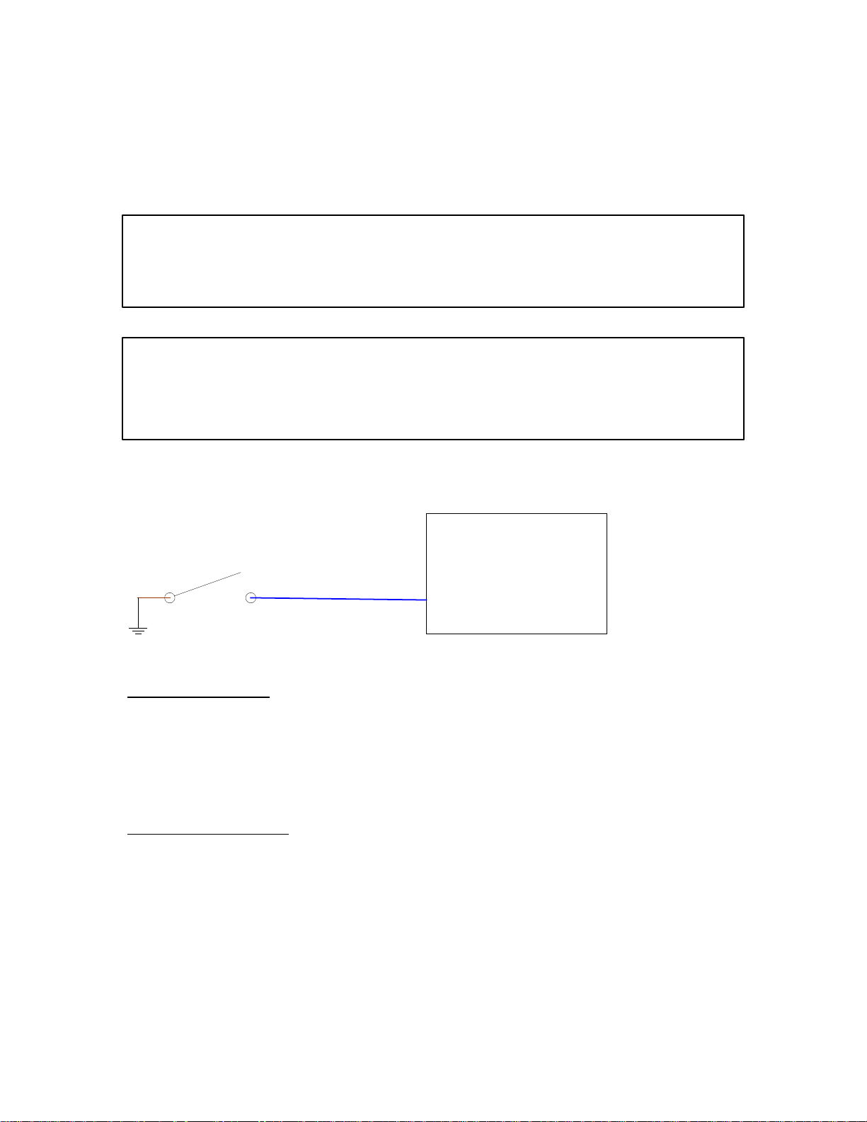
S14 Pressure Switch Circuit:
S14
WEDGE
W239
W237
Blu
J1-11
CONTROLLER
Circuit Description:
S14 is a normally open, 12 psi pressure switch. When the safety valve opens,
S14’s pressure is raised above 12 psi and the switch closes. This grounds the
WEDGE input, indicating the safety valve has opened.
Component Location:
S14 is screwed into the outlet of the safety valve.
50
Page 52

TROUBLESHOOTING STEPS
Code 36
Action Result
Verify PT1 pressure transducer is reading
correctly.
51
Page 53
COMPRESSOR CODE 50
Separator Tank Temperature
Explanation:
The WEDGE has received a separator tank temperature from RT1 that is
greater than 247 degrees F.
Effect:
Code 50 is a shutdown condition and will shutdown the machine.
TROUBLESHOOTING STEPS
Code 50
Action
Step1:
Check for package air inlet restrictions.
Step 2:
Check for dirty or clogged coolers.
Result
52
Page 54
COMPRESSOR CODE 51
Machine ID Not Valid
Explanation:
The WEDGE has not received a reading from the machine ID plug.
Effect:
Code 51 is a shutdown condition and since a valid machine ID has not been
received the machine will shutdown.
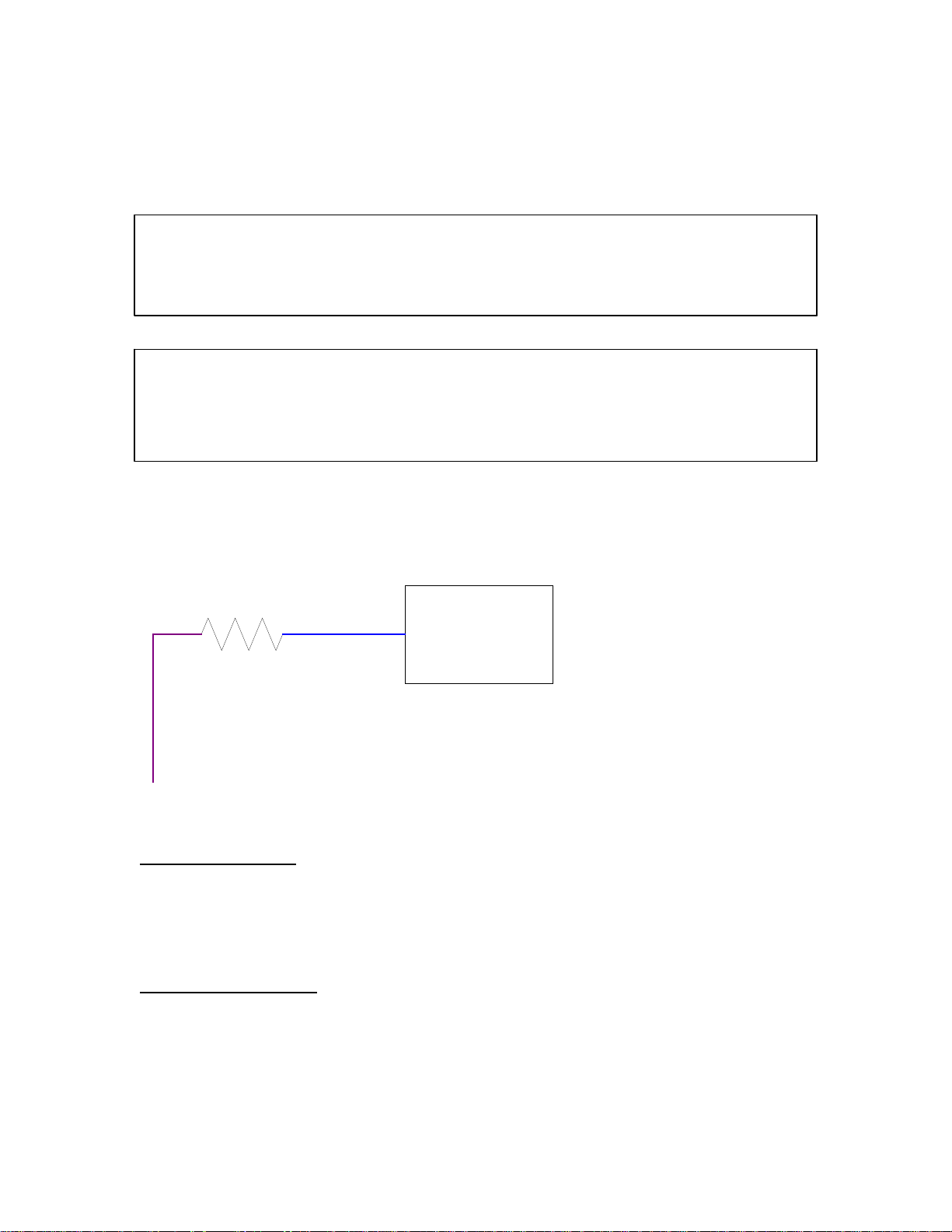
Machine ID Plug Circuit:
R2
BLU
VIO
+ 5 VDC
J1-15
WEDGE
CONTROLLER
Circuit Description:
The machine ID plug is a resistor plug connected to one of the analog inputs to
the WEDGE. % VDC is connected to the other pin of the resistor. The resistor
values are different for each machine model.
Component Location:
The machine ID plug is located behind the control panel box, inside the machine.
53
Page 55
TROUBLESHOOTING STEPS
Code 51
Action
Step1:
Make sure an ID plug is installed.
Step 2:
If an ID plug is installed, remove it and measure its resistance.
Step 3:
Check for corrosion at ID Plug Pins.
Result
The ID plug resistance values are
listed in the “Individual Circuit
Diagrams” section of this service
manual.
54
Page 56
COMPRESSOR CODE 53
RT1, Discharge Temperature Sensor Fault
Explanation:
The WEDGE has received an out of limits reading from the RT1 temperature
sensor. This reading could be on the high or low end of the range. It is
out of the normal range for temperature measurement.
Effect:
Code 53 is a shutdown condition and will shutdown the machine.
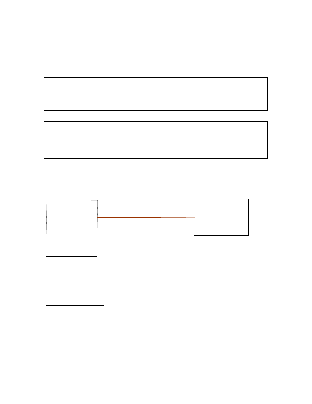
RT1 Temperature Sensor Circuit:
1
W067
Yel
J1-4
R
T
1
T
m
e
p
r
e
t
u
a
r
S
e
n
e
s
o
r
W024
2
Brn
J1-6
WEDGE
CONTROLLER
Circuit Description:
The thermistor temperature sensor connects to the WEDGE controller as shown
in the schematic above. The temperature range of RT1 is –30 to 255 degress F.
The thermistor is a 10K ohm device.
Component Location:
RT1 thermistor is located in the side of the separator tank.
55
Page 57

TROUBLESHOOTING STEPS
Code 53
Action
Step1:
Substitute the thermistor simulator (I-R # 22073878) for RT1
Use the WEDGE service diagnostics to read the value for RT1
It should be approximately 32 degrees F.
Result
Should read appx. 32 Deg F
If not, there is a harness or
WEDGE problem.
56
Page 58
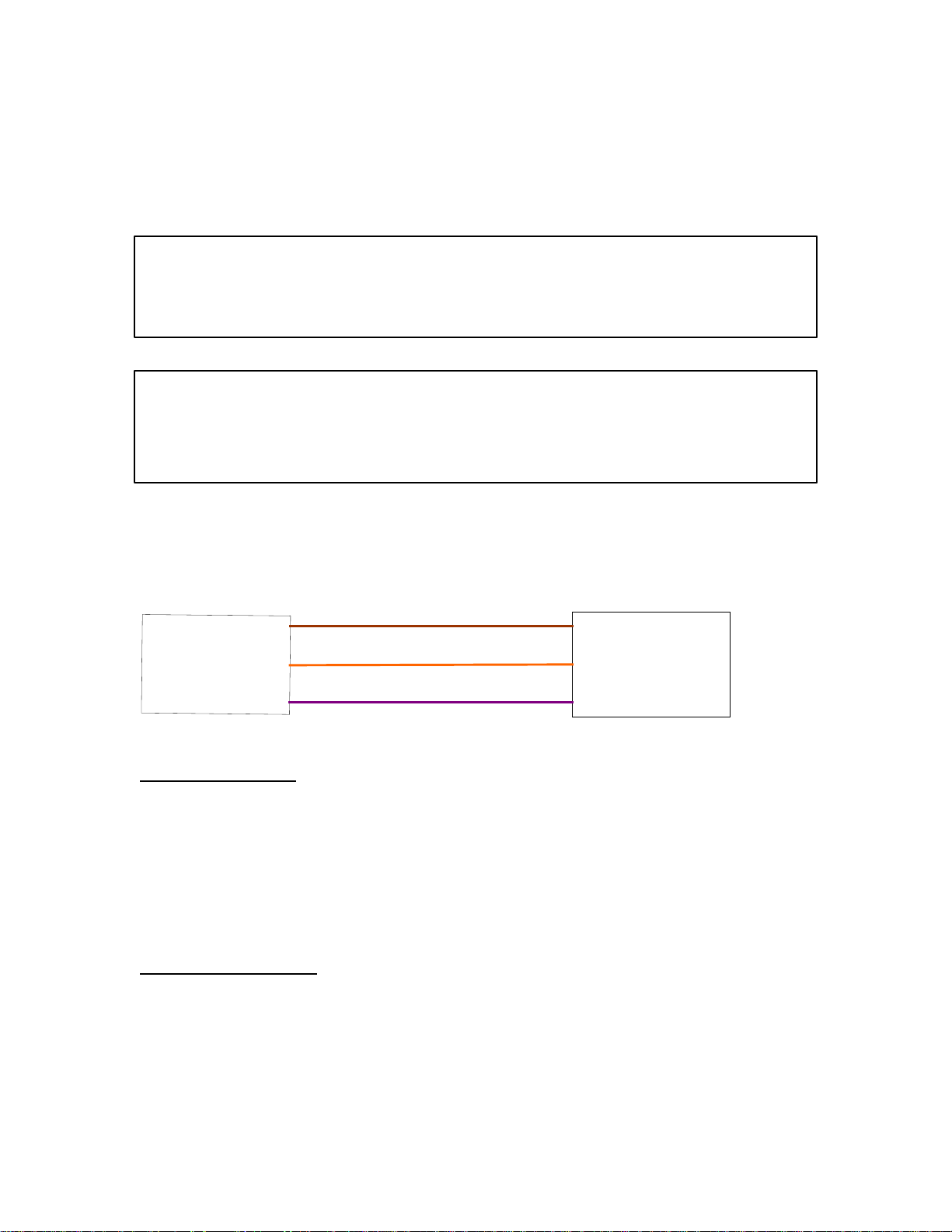
COMPRESSOR CODE 54
PT2 Regulation System Sensor Fault
Explanation:
The WEDGE has received an out of limits reading from the PT2 pressure
transducer. This reading could be on the high or low end of the range. It is
out of the normal range for pressure.
Effect:
Code 54 is an ALERT condition and will not shutdown the machine.
PT2 Pressure Transducer Circuit:
A
W21
Gnd
Brn
J1-8
P
2
T
P
e
s
r
s
e
r
u
T
a
r
s
n
u
d
c
e
r
C
W100
W101
B
Sig
+5 VDC
Orn
Vio
J1-9
J1-10
WEDGE
CONTROLLER
Circuit Description:
The pressure transducer is a 3-wire device that connects to the WEDGE
controller as shown in the schematic above. The violet wire (W101) is the 5 VDC
excitation supply. This is spliced in the harness near the breakout for the
harness branch that goes to the separator tank. The “sig” wire is the output
signal that has a range o .45 to 4.5 volts DC. The pressure range of this
transducer is 0 – 100 psig.
Component Location:
PT2 pressure transducer is located in the pneumatic circuit near the compressor
inlet valve.
57
Page 59

TROUBLESHOOTING STEPS
Code 54
Action
Step1:
Substitute the pressure transducer simulator (I-R # 22168868)
for PT2. Use the WEDGE service diagnostics to read the value
for PT2. It should be approximately 30 – 50 psi.
Result
Should read 30 – 50 psi.
If not, there is a harness or
WEDGE problem.
58
Page 60
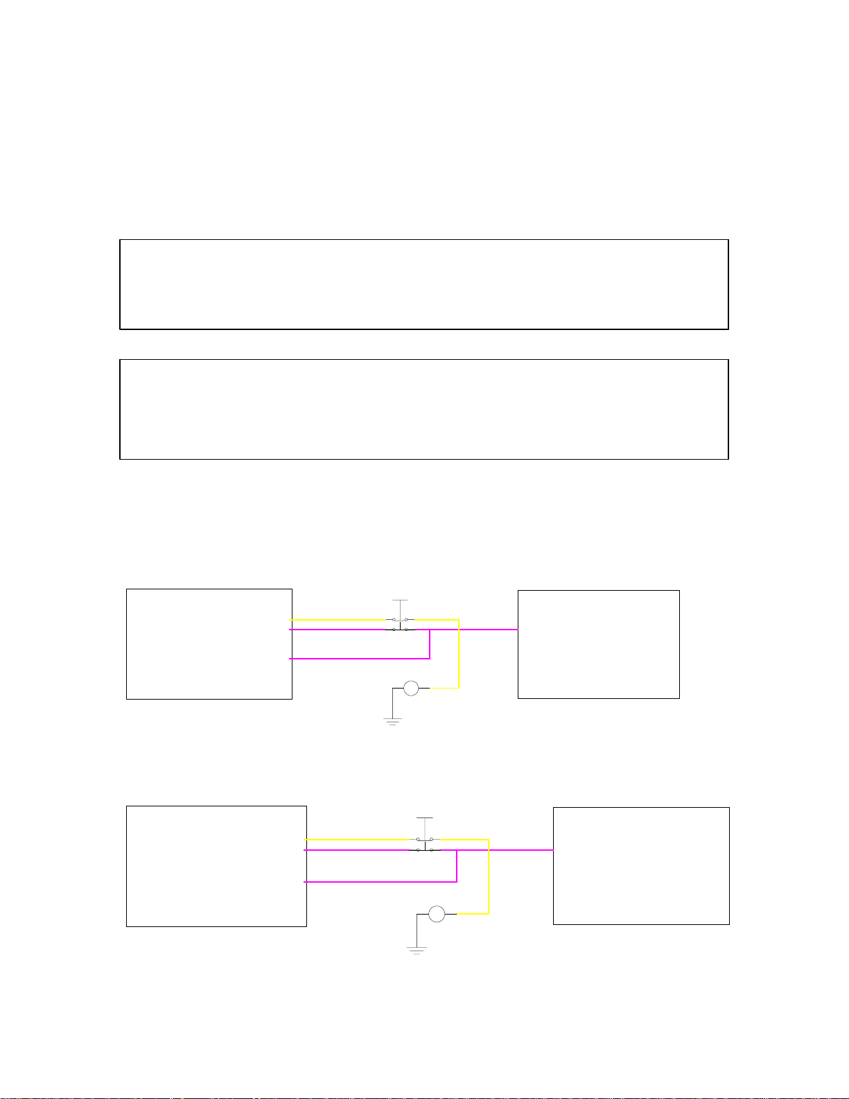
COMPRESSOR CODE 55
Estop Button
Explanation:
The WEDGE has received an indication that the emergency stop button has
been pressed.
Effect:
Code 55 is a shutdown condition and will shutdown the machine. If the machine
Is in the cranking mode when estop is pressed, the starter will be disengaged
simultaneously with engine key switch signal turn off.
Emergency Stop Button Circuit:
S4
Yel
Vio
34
K1
J2-38
Vio
CUMMINS
ENGINE
CONTROLLER
WEDGE
CONTROLLER
J1-28
J1-24
J1-22
2
1
S4
2
Yel
1
34
K1
J2-26
Vio
CAT
ENGINE
CONTROLLER
WEDGE
CONTROLLER
J1-28
J1-24
J1-22 Vio
59
Page 61
Circuit Description:
The estop button is in series with the engine key switch signal and the auxiliary
start relay, K1. Pressing the button opens both of these circuits simultaneously.
The WEDGE reads a sense input that is connected to the estop button to
determine if the estop button is pressed.
Component Location:
The estop button is located above the machine control panel on the front of the
machine.
TROUBLESHOOTING STEPS
Code 55
Action
Step1:
If the estop button is installed, determine if it is pressed.
Step 2:
If the estop button is not installed, a jumper plug will be
installed in the harness at the connection point for the estop
button, P9.
Result
Release the estop button to
operate the machine.
Verify the jumper plug is functional
Step 3:
Perform a continuity check of the harness wires from the
WEDGE through the jumper plug to the engine connector.
60
Page 62
COMPRESSOR CODE 56
Minimum Pressure Not Met
Explanation:
The separator tank has not reached 50 psi within 20 seconds from time engine
starts.
Effect:
Code 56 is an ALERT condition and will not halt machine operation.
TROUBLESHOOTING STEPS
Code 56
Action
Step1:
Check air piping system for restriction.
Step 2:
Verify engine speed has increased to 1800 rpm when Service
Air switch is pressed.
Result
61
Page 63
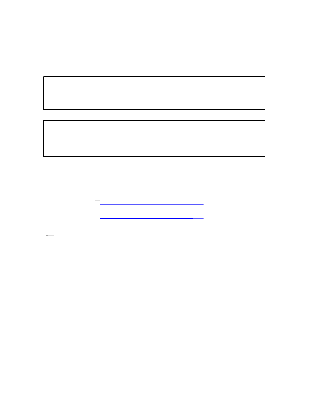
COMPRESSOR CODE 70
Serial Communications
Explanation:
The WEDGE controller cannot communicate with an external computer over the
RS232 serial link.
Effect:
This code can only occur when a laptop computer or PDA Service Tool is
Connected to the WEDGE. The WEDGE may otherwise be functional and
This event may not be mission disabling.
RS232 Communications Circuit:
J5-B
5
J
S
R
2
2
3
o
C
n
n
e
o
t
c
r
J5-A
TXD
RXD
J1-33
J1-32
WEDGE
CONTROLLER
Circuit Description:
The RS232 serial communications link is used for re-programming the WEDGE controller and is
the communications port used with the PDA Service Tool. The J5 connector contains the RS232
port. It is normally located very close to the WEDGE. There are two signals associated with the
RS232, TXD and RXD. TXD is the transmit signal and RXD is the received signal.
Component Location:
The J5 harness connector is located near the WEDGE controller.
62
Page 64
TROUBLESHOOTING STEPS
Code 70
Action
Step1:
If the current RS232 device (laptop computer, etc.) will not
communicate with the WEDGE, substitute another RS232
device. Note: The second device must have proper software
loaded to communicate with the WEDGE.
Result
If second device will not
communicate with WEDGE,
replace the WEDGE
63
Page 65
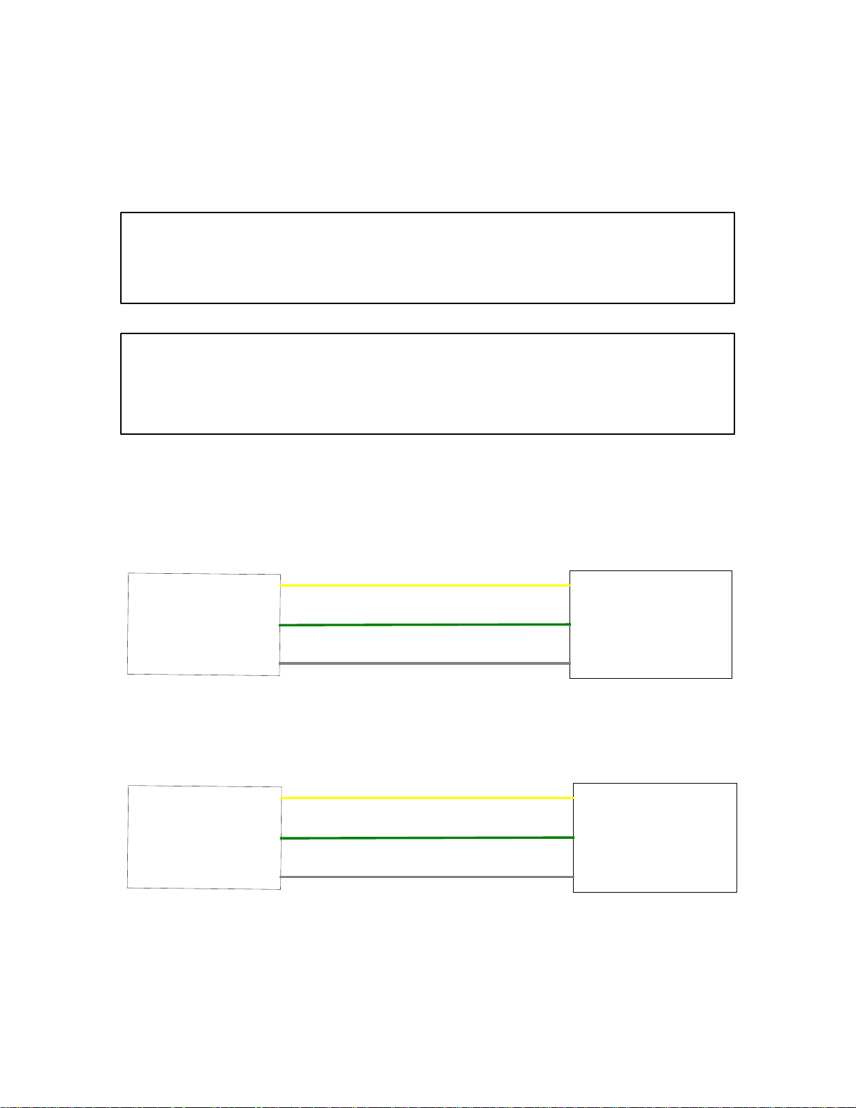
COMPRESSOR CODE 71
CAN Communications
Explanation:
The WEDGE controller cannot communicate with the engine controller. The
J1939 CAN (Controller Area Network) broadcast of engine parameters cannot
be received.
Effect:
The WEDGE will not be able to display engine parameters using the diagnostic
Display function. The compressor will continue to operate since Code 71 is an
ALERT condition.
CAN Communications Circuit:
J2-46
W151
CANH
Yel
J1-35
C
M
U
M
I
N
S
E
N
G
I
N
NT
E
R
O
L
L
E
R
C
O
J2-37
J2-36
W152
W199
CANL
SHLD
Grn
Gry
J1-34
J1-1
WEDGE
CONTROLLER
J2-17
C
AT
E
N
G
N
I
NT
E
R
O
L
L
R
E
C
O
J2-18
J2-16
W151
W152
W150
CANH
CANL
SHLD
Yel
Grn
Gry
J1-35
J1-34
J1-1
WEDGE
CONTROLLER
64
Page 66
J50-G1
J
o
n
h
D
e
e
r
E
C
O
NT
e
N
G
I
N
E
R
O
L
L
E
R
J50-F1
CANH
CANL
SHLD
Yel
Grn
Gry
J1-35
J1-34
J1-1
WEDGE
CONTROLLER
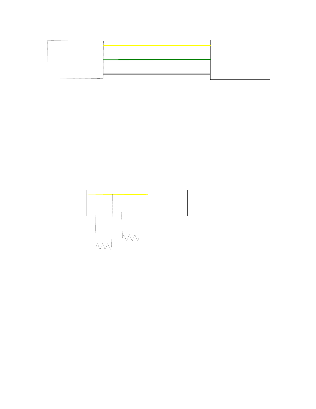
Circuit Description:
The CANH, CANL and SHLD wires are a cable that is located in the main harness. CANH refers
to CAN HI and CANL refers to CAN LO and SHLD is the shield of the CAN cable. This is the
cable that carries the communications between the engine and WEDGE controller and any other
devices that are connected to the CAN cable. This cable is also referred to as the CAN Network
since it may have multiple devices connected to it.
The CAN network has two terminating resistors, one located near the engine controller and one
near the WEDGE controller. The value of each of these resistors is 120 ohms. They are
connected in parallel, as shown below, across the network. The resistors are mounted in a
special Deutsch connector. One connector is tagged R4 and the other is tagged R5.
CANH
CUMMINS
ENGINE
CONTROLLER
CANL
WEDGE
CONTROLLER
R4
R5
Component Location:
The Cummins engine controller is located on the left side of the engine. Connector J2 is located
on the left side of the controller and is the OEM connector. The machine harness (P2) plugs into
the J2 connector. The CAT controller is located on the left side of the engine. The harness P2
connector plugs into the CAT J61 customer connector located near the controller.
The WEDGE controller is mounted to the machine control panel on the back side. Resistor R5 is
stubbed out of the harness near the engine controller and resistor R4 is stubbed out of the
harness near the WEDGE controller.
65
Page 67

TROUBLESHOOTING STEPS
Code 71
Action Result
Step 1:
Verify P1 harness connector pins 34, 35, and 1 are firmly seated into
The connector at the WEDGE controller.
Step 2:
Verify P2 harness connector pins 37, 46, and 36 for Cummins engine
or pins 17, 18, and 16 for CAT engine are firmly seated into the
connector at the engine electronic controller.
Step 3:
Setup the digital multimeter to read ohms. (Refer to the section in this
manual on how to use the multimeter). Disconnect P1 harness
connector from the WEDGE controller. If the engine is a Cummins,
disconnect the P2 harness connector from the engine controller.
If the engine is a CAT engine, leave P2 connected to the engine
Controller.
Connect one of the multimeter test leads to P1-34 and the other test
Lead to P1-35.
Step 4:
If you did not get the results of Step 3, there is a problem with the wiring
harness. This problem could be a defective splice, broken wire or
defective wire connection at a pin. The CANH and CANL wires should
be tested for continuity from P1 to P2. The resistor stub outs should be
tested for continuity.
Step 5:
Setup the multimeter to read DC volts. (Refer to the section in this
manual on how to use the multimeter). The harness should be
connected to the engine controller and the WEDGE controller.
Turn the machine power to the “ON” position, but do not start the
engine.
Using insulation piercing probes (I-R P/N 22216725),
connect the red multimeter lead to P1-34 wire and connect the black
multimeter lead to the battery negative post or one of the brown wires
on the back of the control panel.
Meter should read
approximately 60 ohms. If so,
go to Step 5. If not, go to Step
4.
Make harness repairs as
necessary.
66
Page 68

Disconnect the test lead from P1-34 wire and connect to P1-35 wire.
Multimeter should read
approximately 2.5 volts DC.
Multimeter should read
approximately 2.5 volts DC.
If 2.5 volts cannot be read,
replace WEDGE controller. If
WEDGE controller is OK,
harness should be checked as
outlined in Step 4.
67
Page 69
COMPRESSOR CODE 73
Auto Start Stop Controller Communications Failure
Explanation:
The WEDGE has not been able to communicate with the Auto Start Stop
controller for 17 seconds. A communications failure is determined.
Effect:
Code 73 is an ALERT condition and will not stop the machine. The Auto Start
system may not function properly due to communications failure.
TROUBLESHOOTING STEPS
Code 73
Action
Step1:
If CAN communications is OK with the engine, check the CANpower stub connection for the Auto Start module. If CAN with
the engine is not working, check CAN wiring in harness.
Step 2:
Verify the Auto Start controller has power and ground.
Step 3:
Replace the Auto Start module.
Result
68
Page 70

69
Page 71

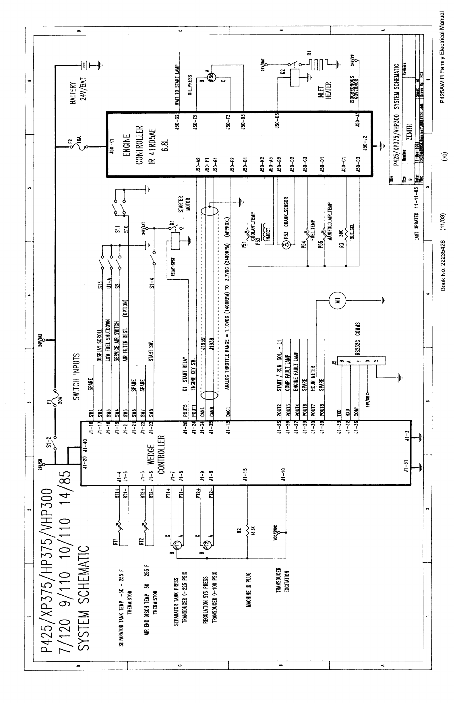
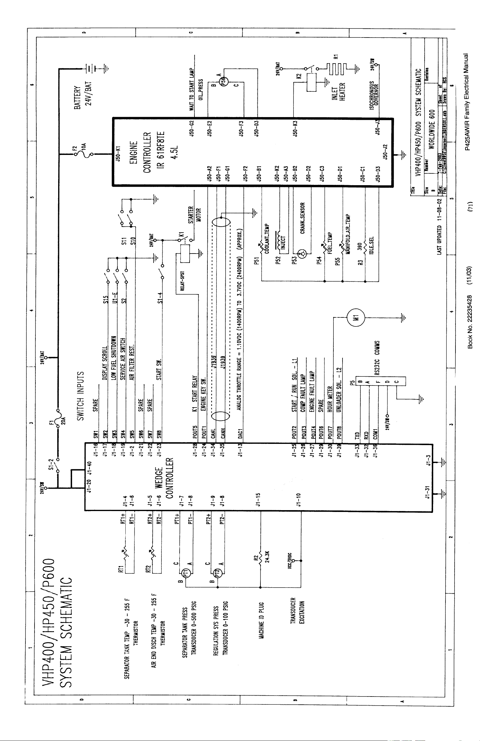
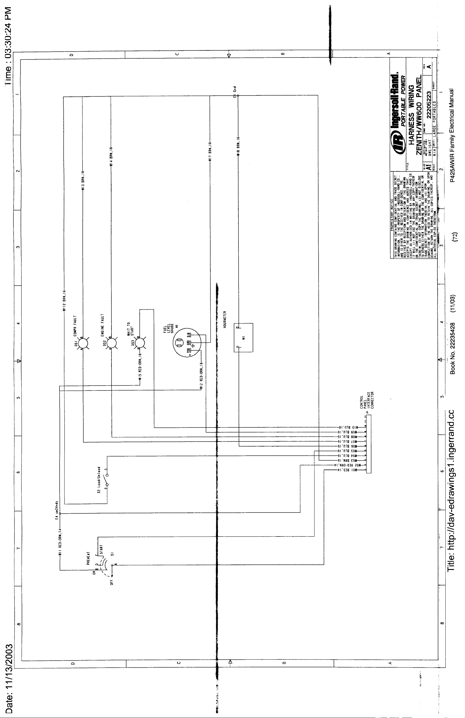
SECTION 5
SYSTEM SCHEMATIC DIAGRAMS
Book No. 22235428 (11/03)
69()
P425AWIR Family Electrical Manual
Page 72
Page 73
Page 74
Page 75
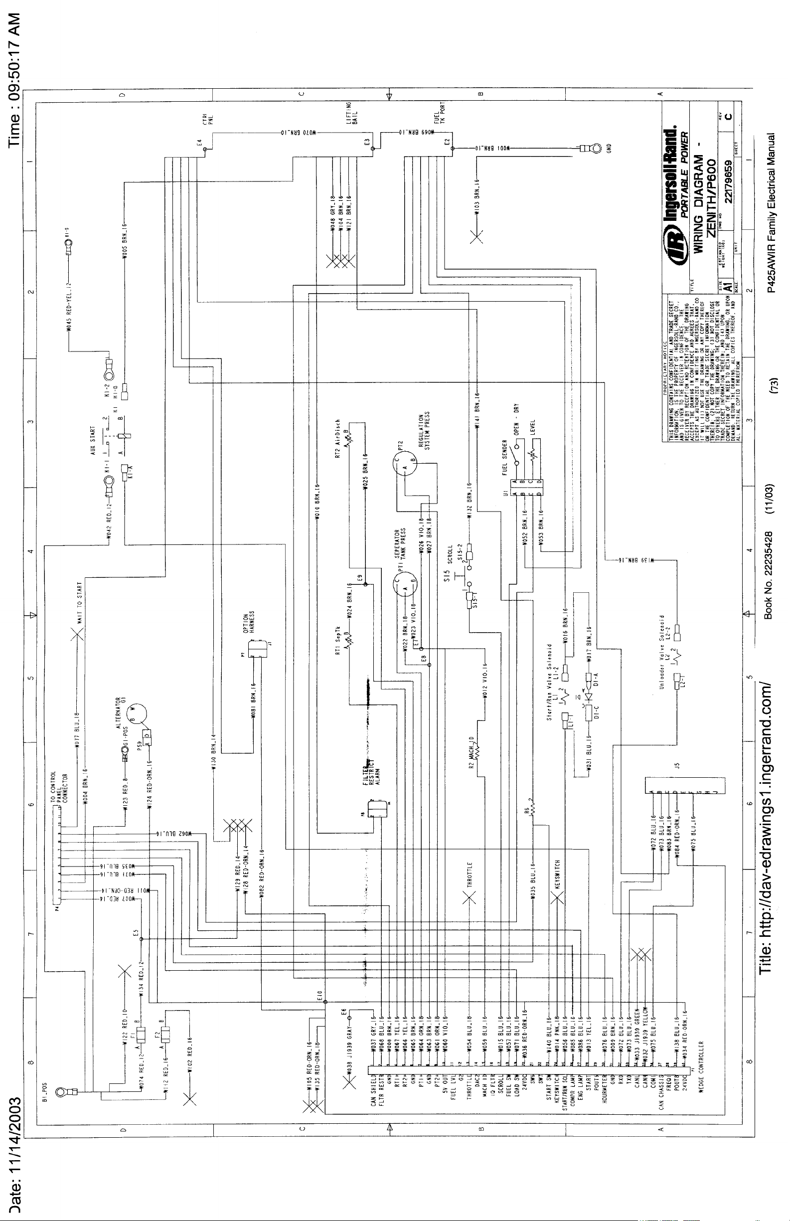
Page 76
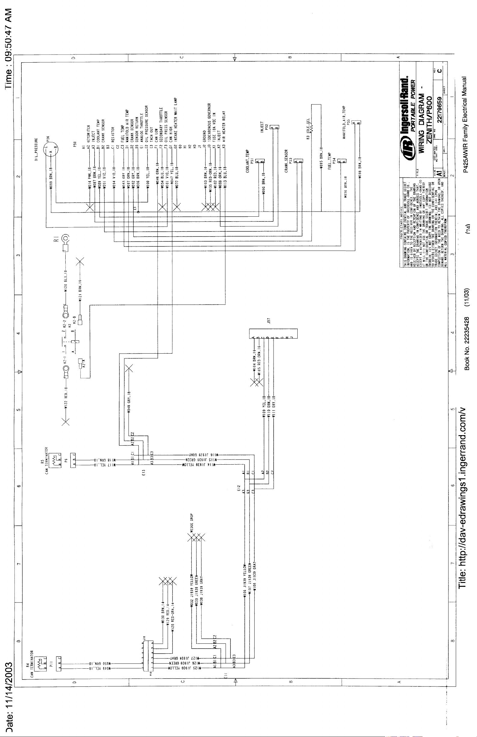
Page 77

SECTION 6
ELECTRONIC COMPONENT
LOCATION DRAWINGS (not available)
Book No. 22235428 (11/03)
75()
P425AWIR Family Electrical Manual
Page 78

HARNESS CONNECTOR LOCATIONS
J1: Located on back of WEDGE controller
J50: 30 pin connector located on engine electronic controller
P4: 12 pin connector located on back of control panel box
P6: 3 pin connector for termination resistor on CAN backbone near Engine electronic controller
J57: 9 pin connector for engine datalink service, located near engine controller
P11: 3 pin connector for termination resistor on CAN backbone near batteries
J5: 9 pin connector for RS232 communications, located behind control panel
P7: 2 pin connector for option harness located behind control panel
Book No. 22235428 (11/03)
76()
P425AWIR Family Electrical Manual
Page 79

SECTION 7
INDIVIDUAL CIRCUIT DIAGRAMS
Book No. 22235428 (11/03)
77()
P425AWIR Family Electrical Manual
Page 80
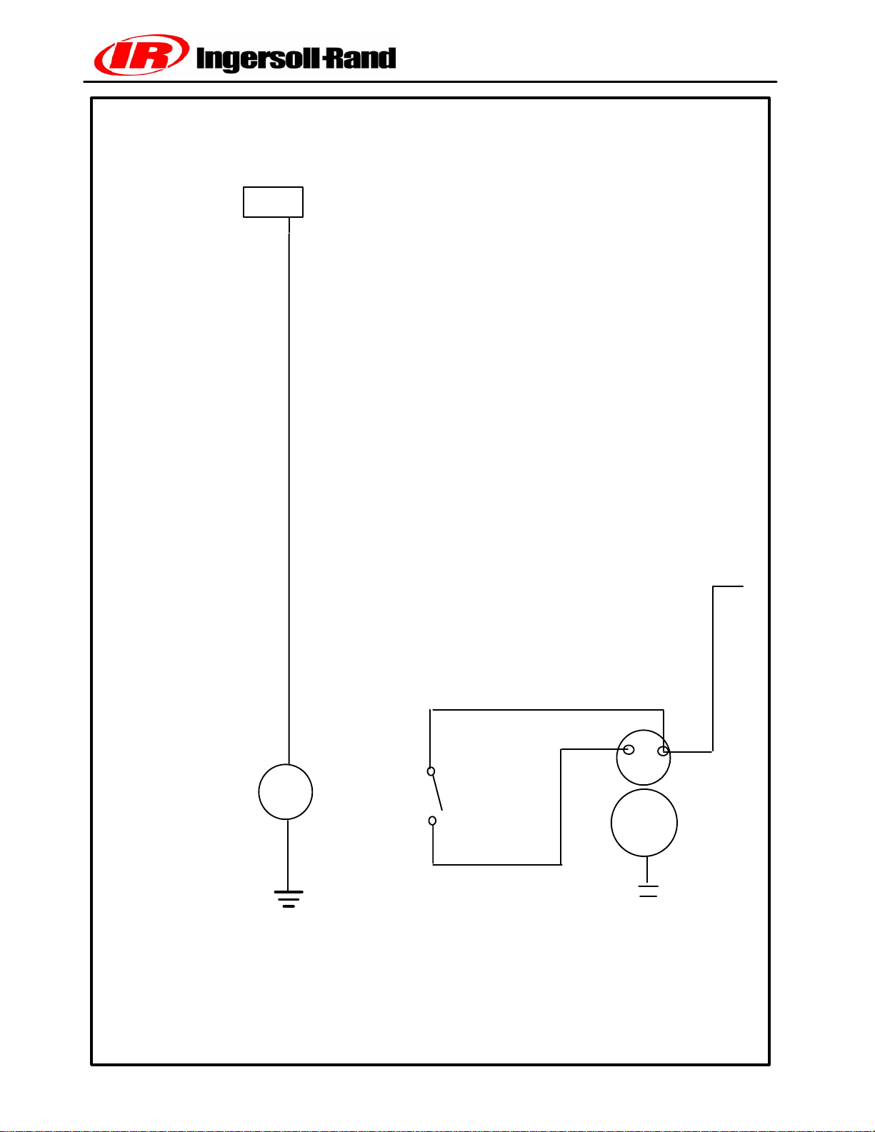
ENGINE START CIRCUIT
WEDGE
J1--28
P1--28
YEL
WO13
CHART A1
START
RELAY
K1
-- -- -- -- -- -- -- --
W005
BRN
W042 RED
1
K1
2
W045 Red--Yel
S
24VDC
B+
STARTER
B1
M
Book No. 22235428 (11/03)
78()
V1.5
P425AWIR Family Electrical Manual
Page 81

CIRCUIT DESCRIPTION
The WEDGE drives the engine starter through the auxiliary start
relay, K1.
K1 is mounted on the lifting rail near the engine.
K1 has a single set of contacts that connect to the starter solenoid.
The control signal leaving the WEDGE on J1--28 passes through the
W1 harness and through a jumper plug. The jumper plug is replaced
with an ESTOP switch for ESA versions.
CIRCUIT TROUBLESHOOTING
If the starter will not engage during a crank cycle, check the voltage
at the coil of K1 during the crank cycle. It should be 14--22VDC. If
voltage is not at K1, check for voltage back through the ESTOP
jumper and to the WEDGE.
If voltage is at K1 coil, verify voltage is sent to the starter solenoid
by K1 contact.
Voltage available at the starter solenoid during a no--crank condition
indicates a starter problem.
Book No. 22235428 (11/03)
79()
P425AWIR Family Electrical Manual
Page 82
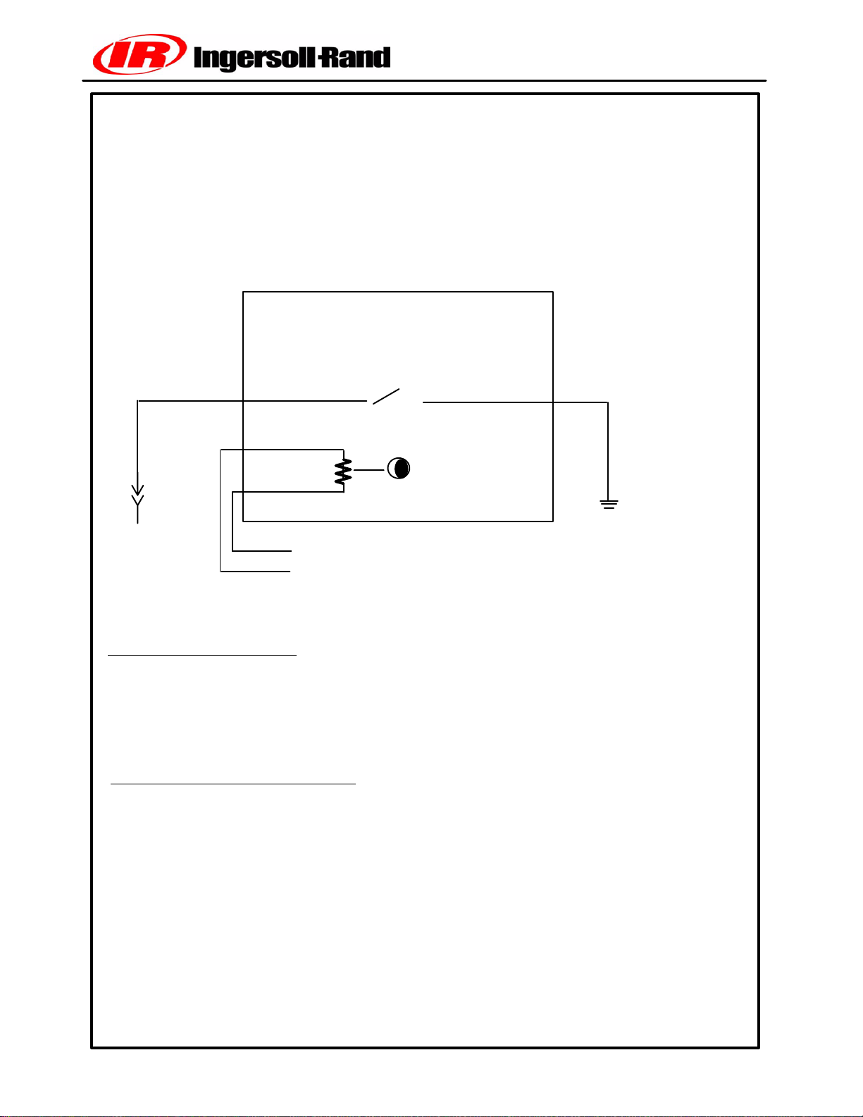
FUEL SENDER CIRCUIT
CHART B1
W057
BLU
P1--18
J1--18
WEDGE
A
B
A
o
→
to control panel fuel level
→
to ground
o
U1
Fuel Level Sender
B
W052
BRN
CIRCUIT DESCRIPTION
The fuel sender is a resistive device that sends a 10--180 ohm signal to the fuel gauge
indicating fuel level. It also contains two switches, one for low fuel level and another
that will shutdown the machine when the fuel reaches this level. These two switch
inputs connect to the WEDGE controller.
CIRCUIT TROUBLESHOOTING
If the fuel reading appears incorrect, check the fuel level in the tanks to see if it
corresponds with the gauge. If not, remove the fuel sender and disconnect the
harness plug. Connect an ohmeter across terminals A and B on the Packard
Weather--Pack connector. Tilting the sender tube should produce resistance
reading between 10 and 180 ohms. If not, replace the sender.
The two switches can be checked with the sender removed from the tank. Use an
ohmeter to verify switch operation. Tilting the sender tube back and forth should
activate the switches.
Book No. 22235428 (11/03)
80()
P425AWIR Family Electrical Manual
Page 83
RT1 SEPARATOR TANK TEMPERATURE
CIRCUIT
CHART C1
Temp_C
Temp_F
--20 --4 25,490
--10 14 18,088
--5 23 12,221
0 32 9,369
5 41 7,240
15 59 4,427
25 77 2,786
40 104 1460
60 140 668.7
70 158 467.2
90 194 241.0
100 212 177.5
105 221 153.1
110 230 132.8
Resistance
(Ohms)
WEDGE
CONTROLLER
J1--4
W1 P1--4
YEL
W1 W067
1
RT1
SEPARATOR TANK
TEMP SENSOR
2
BRN
W1 W024
W1 P1--6
J1--6
WEDGE
CONTROLLER
CIRCUIT DESCRIPTION
Separator tank temperature is read by RT1 thermistor. It is mounted in the side of the
separator tank and connects to the W1 harness. The temperature range is --30 to
255_F.
CIRCUIT TROUBLESHOOTING
If the WEDGE Controller has an incorrect reading for the RT1 channel, disconnect the
thermistor and install the Thermistor Simulator Plug (IR# 22073878) into the harness
connector. Read the channel again and it should read 32 degrees F ± 5 degrees
(0C ± 3C). If the reading is correct, replace the thermistor. If not, disconnect the
WEDGE Controller P1 connector. Connect an ohmmeter between pins P1--4 and
P1--6. The ohmmeter should read 33.2K ohms ±1%. If the reading is correct, replace
the WEDGE Controller. If not, there is a problem with the W1 harness or the P1--4,
P1--6 connector pins.
Book No. 22235428 (11/03)
81()
P425AWIR Family Electrical Manual
Page 84
RT2 AIREND DISCHARGE TEMP
CHART D1
WEDGE
CONTROLLER
Temp_C
Temp_F
--20 --4 25,490
--10 14 18,088
--5 23 12,221
0 32 9,369
5 41 7,240
15 59 4,427
25 77 2,786
40 104 1460
60 140 668.7
70 158 467.2
90 194 241.0
100 212 177.5
105 221 153.1
110 230 132.8
Resistance
(Ohms)
J1--5
W1 P1--5
YEL
W1 W066
1
RT2
AIREND DISCHARGE
TEMP SENSOR
2
BRN
W1 W025
W1 P1--6
J1--6
WEDGE
CONTROLLER
CIRCUIT DESCRIPTION
Airend discharge temperature is read by RT2 thermistor. It is mounted in the airend
discharge piping and connects to the W1 harness. The temperature range is --30 to
255_F.
CIRCUIT TROUBLESHOOTING
If the WEDGE Controller has an incorrect reading for the RT2 channel, disconnect the
thermistor and install the Thermistor Simulator Plug (IR# 22073878) into the harness
connector. Read the channel again and it should read 32 degrees F ± 5 degrees
(0C ± 3C). If the reading is correct, replace the thermistor. If not, disconnect the
WEDGE Controller P1 connector. Connect an ohmmeter between pins P1--5 and
P1--6. The ohmmeter should read 33.2K ohms ±1%. If the reading is correct, replace
the WEDGE Controller. If not, there is a problem with the W1 harness or the P1--5,
P1--6 connector pins.
Book No. 22235428 (11/03)
82()
P425AWIR Family Electrical Manual
Page 85
PT1 SEPARATOR TANK
PRESSURE CIRCUIT
CHART E1
W1
HARNESS
WEDGE
CONTROLLER
A
GND
C
SIG (+)
J1--8
J1--7
P1--8 BRN
W022
P1--7 ORN
W064
PT1
SEPARAT OR TANK
PRESSURE TRANSDUCER
B
5VDC+
J1--10
P1--10 VIO
W023
CIRCUIT DESCRIPTION
The WEDGE reads separator tank pressure from PT1. It is a gauge pressure
transducer mounted on the separator tank. The WEDGE provides 5 VDC excitation
voltage to pin B (+5) and pin A (GND). The pressure signal on pin C connects to the
WEDGE input. The signal range is .45 to 4.5 volts. The transducer range is 0 to 225
psig.
CIRCUIT TROUBLESHOOTING
To verify the operation of PT1, connect a gauge in parallel with it. The test gauge
should be at least 1% accuracy to match the accuracy of PT1. Use the WEDGE
diagnostics to display the readings of PT1. If PT1 does not track the test gauge,
replace it.
Book No. 22235428 (11/03)
83()
P425AWIR Family Electrical Manual
Page 86
PT2 REGULATION SYSTEM
PRESSURE CIRCUIT
CHART F1
W1
WEDGE
CONTROLLER
HARNESS
A
GND
C
SIG (+)
PT2
REGULATION SYSTEM
PRESSURE TRANSDUCER
J1--8
J1--9
P1--8 BRN
W027
P1--9 ORN
W061
B
J1--10
P1--10 VIO
5VDC+
W026
CIRCUIT DESCRIPTION
The WEDGE reads regulation system pressure from PT2. It is a gauge pressure
transducer mounted near the inlet unloader. The WEDGE controller provides 5 VDC
excitation voltage to pin B (+5) and pin A (GND). The pressure signal on pin C
connects to the WEDGE input. The signal range is .45 to 4.5 volts. The transducer
range is 0 to 100 psig.
CIRCUIT TROUBLESHOOTING
To check the operation of PT2, connect a gauge in parallel with it. The test gauge
should be at least 1% accuracy to match the accuracy of PT2. Use the WEDGE
diagnostics to display the readings of PT2. If PT2 does not track the test gauge,
replace it.
Book No. 22235428 (11/03)
84()
P425AWIR Family Electrical Manual
Page 87
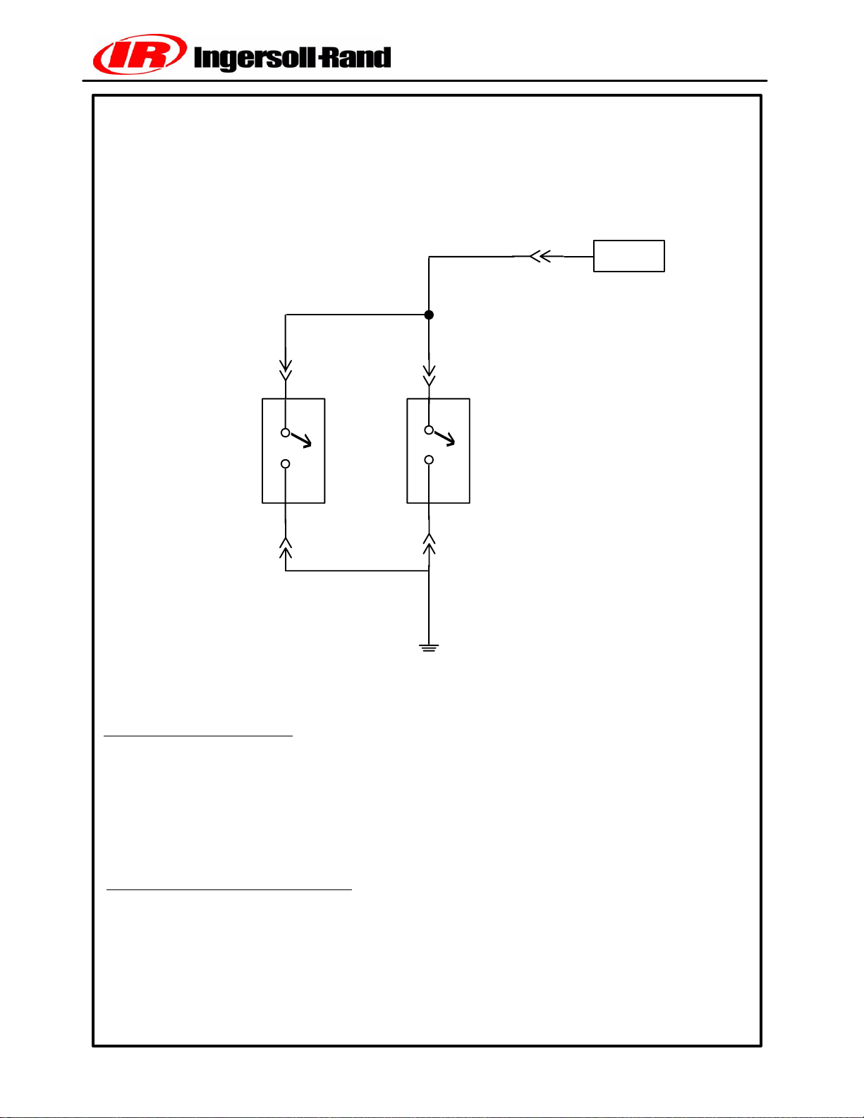
S10, S11 AIR FILTER SWITCHES
CHART I1
S10--1
S10
W068 BLU
P1--2 J1--2
W162
BLU
S11--1
S11
W163
BRN
W010
BRN
WEDGE
CIRCUIT DESCRIPTION
The WEDGE reads the air filter switches, S10 and S11. S10 is connected to the
compressor air filter and S11 is connected to the engine air filter. These are normally
open switches and close when the air filter restriction reaches 20 inches of water.
The switches provide a ground connection to an opto coupler input on the WEDGE
controller.
CIRCUIT TROUBLESHOOTING
To verify the circuit operation, another type of switch can be substituted for the filter
switch, or a wire jumper can be used to activate the circuit. Disconnect S10 and S11
and install the test switch or jumper. Closing the test switch or installing the jumper
should activate the circuit, and the “Air Filter” alarm light on the control panel should
light. Forcing the alarm lamp to turn on and off will verify proper circuit operation.
Book No. 22235428 (11/03)
85()
P425AWIR Family Electrical Manual
Page 88

R2 MACHINE ID PLUG
CHART J1
WEDGE
J1--15
P1--15
W059
BLU
R2--1
R2 Resistor
Machine ID Plug
R2--2
W012
VIO
+5 V
CIRCUIT DESCRIPTION
The machine ID plug is used to indicate to the WEDGE controller which type of
machine is connected. The plug consists of a resistor and is connected to one of the
WEDGE analog inputs. The resistor plugs are color coded for easy identification. Refer to table below for color codes. The WEDGE reads the ID plug at power up. If it
cannot read the plug or reads an invalid voltage, a shutdown will be issued with fault
code 51.
The ID plug can be removed and checked with an ohmeter. The table below lists the
resistance values associated with various machines.
ID Plug Color
Grey
Resistance Ω
45300
Machine Model
P425
Book No. 22235428 (11/03)
86()
P425AWIR Family Electrical Manual
Page 89

SECTION 8
ELECTRICAL CONNECTOR INFORMATION
Book No. 22235428 (11/03)
87()
P425AWIR Family Electrical Manual
Page 90

CONNECTOR PARTS INFORMATION
The following is a list of the connector parts used with the harnesses and devices on the HP1600/1300 machine.
Mostconnectorsconsist of1 to4itemsperside (harnessordevice).Thedevices canbelocatedonthe schematics
and then referenced to this list. A connector repair kit, I--R P/N 54749635, containing terminals and housings, is
available for repairs.
Part Manufacturer Part Number
Thermistor Connector:
(RT1, RT2)
Harness Socket Terminal Packard
Harness Housing Packard
Pressure Transducers:
(PT1 -- PT2)
Harness Female Terminal Packard Metri--Pack 54750500
Harness Housing Packard Metri--Pack 54750518
Fuel Level Sender:
(U1)
Harness Female Terminal Packard Weather Pack 54750526
Harness Housing Packard Weather Pack
Sensor male Terminal Packard Weather Pack 54750542
Sensor Housing Packard Weather Pack
Cable Seal Packard Weather Pack 54750567
WEDGE Serial Port / Engine
Diagnostic Port:
J8
Harness Pins Packard
Engine OEM 30 Pin Conn:
Harness Pin Packard
Harness Housing
J1939 CAN Cable:
Harness Socket Deutsch 54699566
Harness Housing Deutsch 54750633
Book No. 22235428 (11/03)
88()
P425AWIR Family Electrical Manual
Page 91

REMOVAL TOOL USAGE
Terminal
Part Number Manufacturer Removal Tool No. Manufacturer
Crimp Tool No.
54699541 Deutsch 54699632 22216667
54699558 54699632 22216667
54699582 54699640 22216675
54699590 54699640 22216675
54750500 Packard Metri--Pack 54749643 12155975
54750674 54749643 12155975
54750526 Packard Weather Pack 54729660 12155975
54750542 54729660 12155975
54699525 Deutsch 54699624 22216667
54699509 54699616 22216667
54699533 54699624 22216667
54699566 54699632 22216667
Book No. 22235428 (11/03)
89()
P425AWIR Family Electrical Manual
Page 92
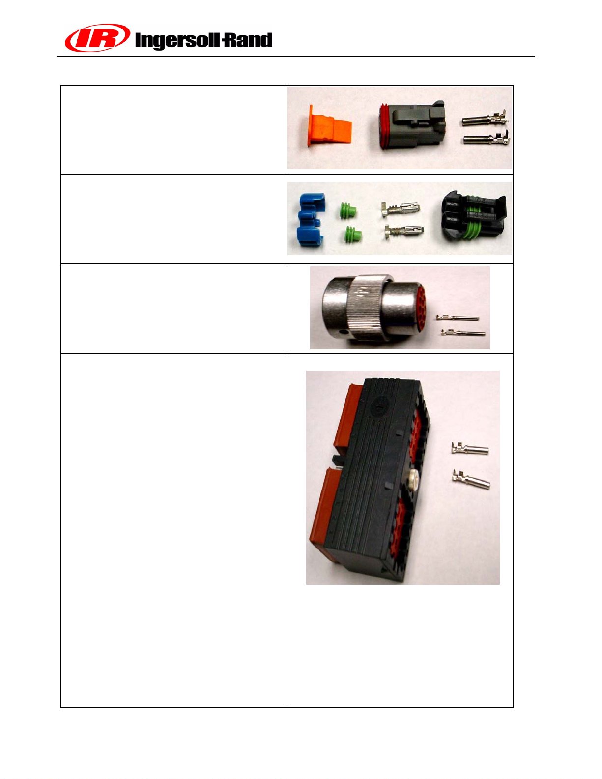
Deutsch DT Series Connector
(Note the orange wedgelock)
Packard Metri Pack Series Connector
(Note the green wire seals and blue Terminal
Position Assurance Connection)
Deutsch HD Series Connector
Deutsch DRC Series Connector
It is very important that connectors be properly
assembled. Use of the correct pin crimp tool is
required to ensure high quality terminations. The
manufacturer’s instructions must be followed as to
selection and use o f crimp tools. Improper crimps
not only provide unreliable connections but can
damage the connector housing.
Troubleshooting Harnesses -- For extensive harness troubleshooting, a detailed schematic will be
required. Splice location details can be very useful
since problems do occur at splices.
The proper test adapters are recommended for
harness troubleshooting. Some examples of these
are shown in Section 2 concerning multimeters.
Use of these adapters will prevent harness damage during testing.
The first item to perform during harness troubleshooting is a physical inspection of the harness
for damage. Look for cut or frayed conductors,
melted insulation and conductors pulled from connectors.
The next item to check is connector pin seating.
Ensure the connector pins in the circuit under test
are properly seated in the connector housing. A
tug on the wire should confirm this.
If the harness is not physically damaged and all
connector pins are seated, perform a continuity
check of the circuit conductors. The ohmeter function of the multimeter can be used for this test.
Check to ensure there are not any ground
faults or conductor shorts to ground.
Finally, measure the signals on the circuit
under test. Start at the point of origin of the
signal and verify at as many points along the
harness as possible, ending at the termination
point.
Book No. 22235428 (11/03)
90()
P425AWIR Family Electrical Manual
Page 93
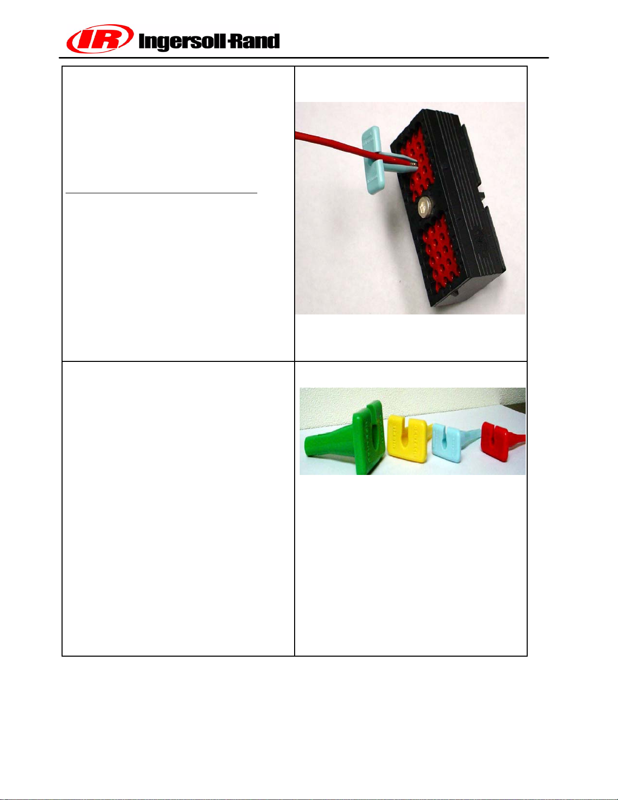
Use of Harness Tools
These pictures describe the proper methods of
use of harness tools.
Proper removal tool usage is shown in the above
picture. The removal tools are color coded as to
wire size. The Table below lists the colors and
wire sizes.
Removal
Tool Color Wire Size IR
P/N
Red 20--24 54699640
Blue 16--18 54699632
Yellow 12--15 54699624
Green 8--10 54699616
The wire is placed into the slot on the removal tool
and the tool is slid along the wire inserted into the
back of the connector. Gently pull on the wire as
the tool is pushed into the connector. The pin
should release from the connector. To insert a pin,
push it into the connector until it locks.
Removal Tools
This picture shows the various removal tools for
the Deutsch connectors.
The following two pages will show how the
Deutsch crimp tools are to be used. One is used
for machined contacts and the other for stamped
and formed contacts.
Book No. 22235428 (11/03)
91()
P425AWIR Family Electrical Manual
Page 94
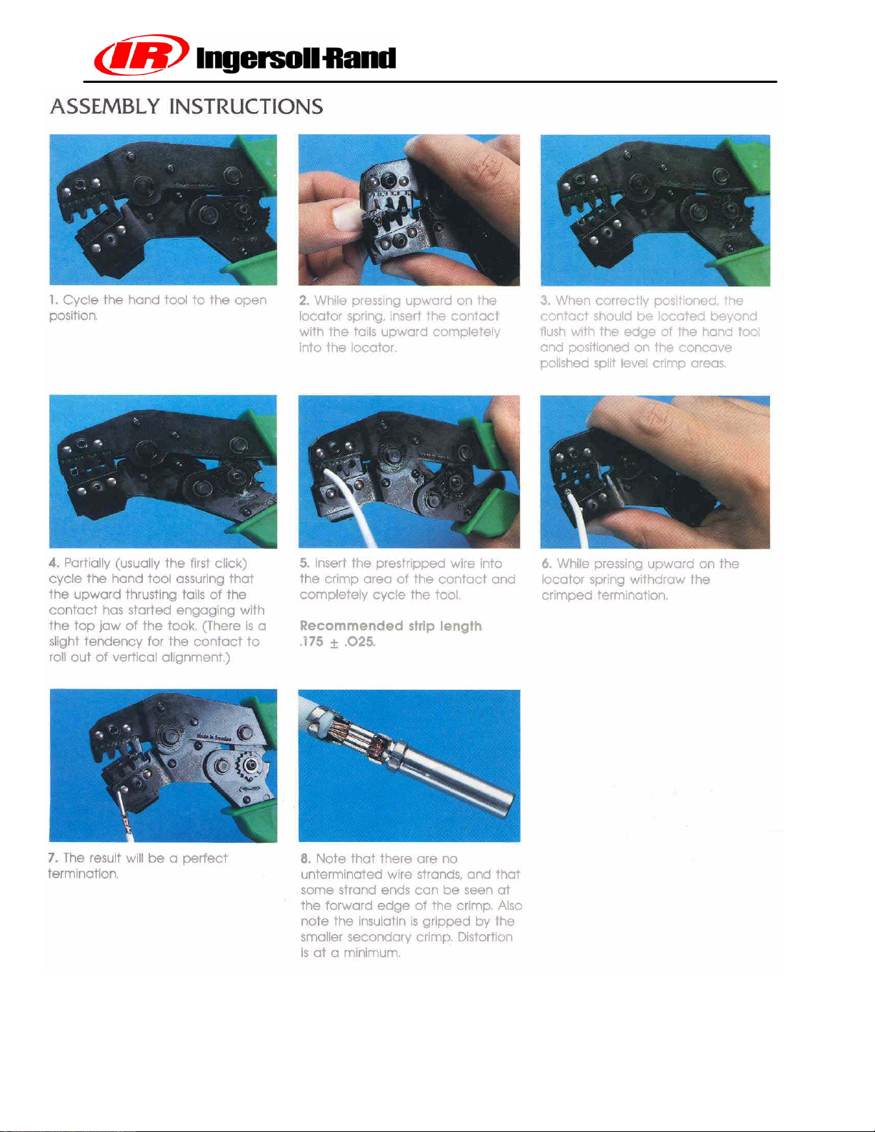
Book No. 22235428 (11/03)
92()
P425AWIR Family Electrical Manual
Page 95
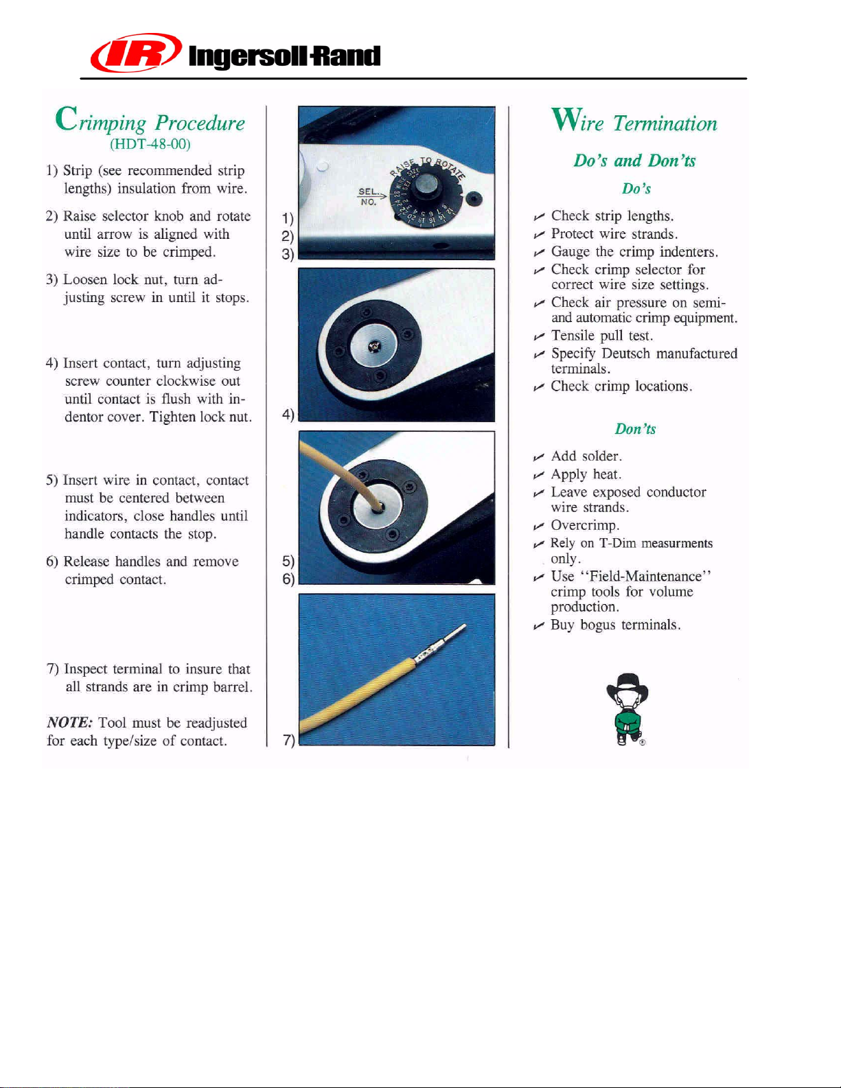
Book No. 22235428 (11/03)
93()
P425AWIR Family Electrical Manual
Page 96
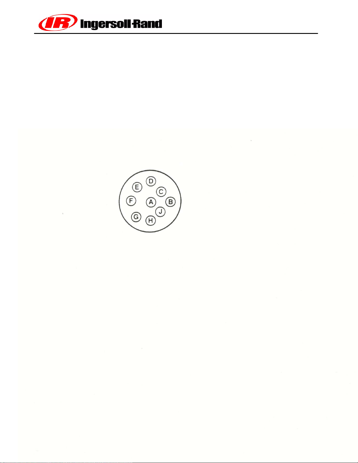
Circular connectors J5 and J8 pinout. J5 is located near the Wedge Controller and
J8 is located near the engine controller. The pinout of these connectors is
the same, however, they are keyed differently.
(View from front side, non--wire side)
Book No. 22235428 (11/03)
94()
P425AWIR Family Electrical Manual
Page 97

SECTION 9
ELECTRICAL PARTS LIST
Book No. 22235428 (11/03)
95()
P425AWIR Family Electrical Manual
Page 98

ELECTRICAL PARTS LIST
Ref Designator Description Part Number
PT1 Sep. Tank Pressure Xducer 54496773
PT2 Reg. Pressure Xducer 36920825
RT1, RT2 Temperature Sensor 36898922
L1 Start/Run Solenoid 36840841
K1, K2 SPST Relay 36853521
Engine Ground Strap 35578194
U1 Fuel Level Sender 54731427
WEDGE Controller 22173579
W1 Chassis Harness 22199061
F1 ATC 20 AMP Fuse 36792083
F2 ATC 10 AMP Fuse 22071591
S15 Diagnostic Switch 54475777
D1 Diode 35376169
R2 Machine ID Plug 22201354
Book No. 22235428 (11/03)
96()
P425AWIR Family Electrical Manual
Page 99

SECTION 10
ALERTS AND SHUTDOWNS LIST
Book No. 22235428 (11/03)
97()
P425AWIR Family Electrical Manual
Page 100
ALERT/SHUTDOWN CONDITIONS Software V1.60
ALERT SHUTDOWN
CODE
Engine Speed < Min. RPM 1 CPRSR Malf 30
Engine Speed > Max. RPM 2 CPRSR Malf 30
Engine Crank Time Exceeded 3 CPRSR Malf 0
Engine Oil Temperature> 252 deg. F 5 CPRSR Malf. 0--6
Intake Manifold Temperature> 180 deg. F 6 CPRSR Malf. 0--7
Water In Fuel 8 CPRSR Malf. 5,6
Engine Not Responding to Throttle Cmd. 10 CPRSR Malf. All
Too Many Start Attempts during Autostart 11 CPRSR Malf 0 All
Engine Shuts Itself Down: reason unknown 29 CPRSR Malf 0 All
Low AE Oil Pressure 31 CPRSR Malf 20 0,2,5
Disch. Temp (RT2) Sensor Fault 32 CPRSR Malf 10 All
Separator Tank (PT1) Sensor Fault 33 CPRSR Malf. All
Separator Tank Pressure >20 PSI during start
attempt (Engine will not crank)
Machine Over Pressure 35 CPRSR Malf 1 0--6
Safety Valve Open 36 CPRSR Malf 2 0--6
Sep. Tank Temp > 247 degrees F 50 CPRSR Malf 3 All
Machine ID Not Valid 51 CPRSR Malf 0 All
Sep. Tank Temp. (Rt1) Sensor Fault 53 CPRSR Malf 10 All
Reg. System Pressure (PT2) Sensor Fault 54 CPRSR Malf. All
Estop Button Pushed 55 CPRSR Malf. 0--6 55 CPRSR Malf 3 0--6
Minimum Pressure Not Met 56 CPRSR Malf. All
Serial Comm. Problem 70 CPRSR Malf. All
CAN Bus Problem 71 CPRSR Malf. All
Auto Start/Stop Module Failure -- No Comm
for 17 seconds
Dedicated Lights:
Low Fuel Level Fuel Level 0--6 Fuel Level 3 All
Air Filter Restriction Soiled Filter
Low Battery Voltage Battery Charging
Engine Oil Pressure < 18 PSI Low Engine Oil
Low Coolant Level Engine Coolant
Engine Coolant Temp > = 215 deg F. High Engine
Engine Coolant Temp> = 220 deg F. High Engine
IQ Filter Restriction IQ Filter Re-
High Discharge Temp.(RT2 > 247 deg. F) High Comp.
73 CPRSRMalf. All
LIGHT
(BLINKS)
Condition
Pressure
Level
Temp
Machine
ID
All^
All
All
0,1,5, 6%
All
CODE
34 CPRSR Malf 0 0--6
LIGHT
(STEADY)
Temp
striction
Temp.
DELAY
(sec)
10 All
3
3 All
Machine
ID
All#
All$
All!
0--6@
CAN Derived Data =
Book No. 22235428 (11/03)
98()
P425AWIR Family Electrical Manual
 Loading...