

Page 1
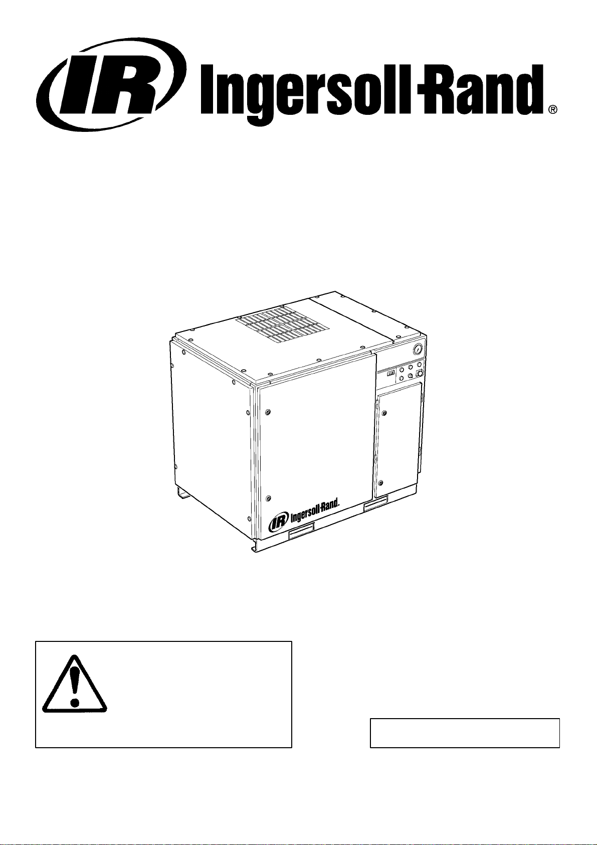
SSR UP6 15, UP6 20, UP6 25, UP6 30
60Hz
OPERATION AND MAINTENANCE MANUAL
This manual contains
important safety information
and must be made available
to personnel who operate and
maintain this machine.
0110190126 –>SERIAL No :
C.C.N. : 22083729 US
DATE : MARCH 2002
Page 2

2
CONTENTS & ABBREVIATIONS
CONTENTS
1 AIRCARE WARRANTY
2 CONTENTS
3 FOREWORD
4 DECALS
9 SAFETY
10 GENERAL INFORMATION
12 INSTALLATION / HANDLING
20 OPERATING INSTRUCTIONS
24 MAINTENANCE
29 TROUBLE SHOOTING
ABBREVIATIONS & SYMBOLS
#### Contact Ingersoll–Rand for serial number
–>#### Up to Serial No.
####–> From Serial No.
* Not illustrated
{ Option
NR Not required
AR As required
SM Sitemaster/Sitepack
HA High ambient machine
WC Watercooled machine
AC Aircooled machine
ERS Energy recovery system
T.E.F.C. Totally enclosed fan cooled motor (IP54)
O.D.P. Open drip proof (motor)
BR Brazilian
CA Canadian French
CN Chinese
DE German
DK Danish
ES Spanish
FI Finnish
FR French
GB English
GR Greek
IT Italian
MX Mexican
NL Dutch
NO Norwegian
PT Portuguese
SE Swedish
US English (USA)
SSR UP6 15, UP6 20, UP6 25, UP6 30
Page 3
FOREWORD
3
The contents of this manual are considered to be proprietary and
confidential to Ingersoll–Rand and should not be reproduced without
the prior written permission of Ingersoll–Rand.
Nothing contained in this document is intended to extend any
promise, warranty or representation, expressed or implied, regarding
the Ingersoll–Rand products described herein. Any such warranties or
other terms and conditions of sale of products shall be in accordance
with the standard terms and conditions of sale for such products, which
are available upon request.
This manual contains instructions and technical data to cover
routine operation and scheduled maintenance tasks by operation and
maintenance staff. Major overhauls are outside the scope of this
manual and should be referred to an authorised Ingersoll–Rand service
department.
The design specification of this machine has been certified as
complying with E.C. directives. Any modification to any part is
absolutely prohibited and would result in the CE certification and
marking being rendered invalid.
All components, accessories, pipes and connectors added to the
compressed air system should be:
. of good quality, procured from a reputable manufacturer and,
wherever possible, be of a type approved by Ingersoll–Rand.
. clearly rated for a pressure at least equal to the machine maximum
allowable working pressure.
. compatible with the compressor lubricant/coolant.
. accompanied with instructions for safe installation, operation and
maintenance.
Details of approved equipment are available from Ingersoll–Rand
Service departments.
The use of non–genuine spare repair parts other than those included within the Ingersoll–Rand approved parts list may create hazardous conditions over which Ingersoll–Rand has no control. Therefore
Ingersoll–Rand does not accept any liabilitity for losses caused by
equipment in which non–approved repair parts are installed. Standard
warranty conditions may be affected.
The intended uses of this machine are outlined below and examples
of unapproved usage are also given, however Ingersoll–Rand cannot
anticipate every application or work situation that may arise.
IF IN DOUBT CONSULT SUPERVISION.
This machine has been designed and supplied for use only in the
following specified conditions and applications:
. Compression of normal ambient air containing no known or
detectable additional gases, vapours. or particles
. Operation within the ambient temperature range specified in the
GENERAL INFORMATION section of this manual.
The use of the machine in any of the situation types listed in
table 1:–
a) Is not approved by Ingersoll–Rand,
b) May impair the safety of users and other persons, and
c) May prejudice any claims made against Ingersoll–Rand.
TABLE 1
Use of the machine to produce compressed air for:
a) direct human consumption
b) indirect human consumption, without suitable filtration and purity
checks.
Use of the machine outside the ambient temperature range
specified i n the GENERAL INFORMATION SECTION of this manual.
Use of the machine where there is any actual or foreseeable risk of
hazardous levels of flammable gases or vapours.
Use of the machine fitted with non Ingersoll–Rand approved
components.
Use of the machine with safety or control components missing or
disabled.
The company accepts no responsibility for errors in translation of
this manual from the original English version.
Ingersoll–Rand reserves the right to make changes and
improvements to products without notice and without incurring any
obligation to make such changes or add such improvements to
products sold previously.
SSR ULTRA PLUS COOLANT is a registered trademark of
Ingersoll–Rand Company USA.
COPYRIGHT 2002
INGERSOLL–RAND COMPANY
SSR UP6 15, UP6 20, UP6 25, UP6 30
Page 4

DECALS4
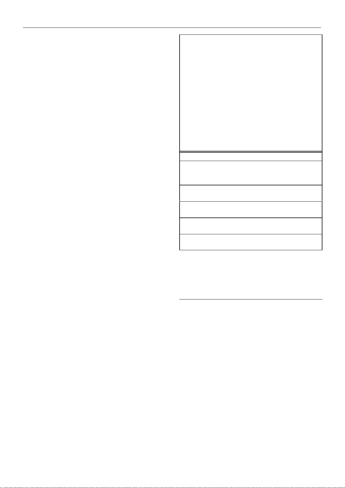
ISO SYMBOLS
GRAPHIC FORM AND MEANING OF ISO SYMBOLS
Prohibition / Mandatory Information / Instructions Warning
Use fork lift truck from this side only. RESET Do not use fork lift truck from this side.
Emergency stop. On (power). Off (power).
AUTOMATIC RESTART MAINTENANCE MAINTENANCE PROHIBITED
FRAGILE KEEP DRY THIS WAY UP
USE NO HOOKS NO SIDE CLAMPS HOURS
SSR UP6 15, UP6 20, UP6 25, UP6 30
Page 5
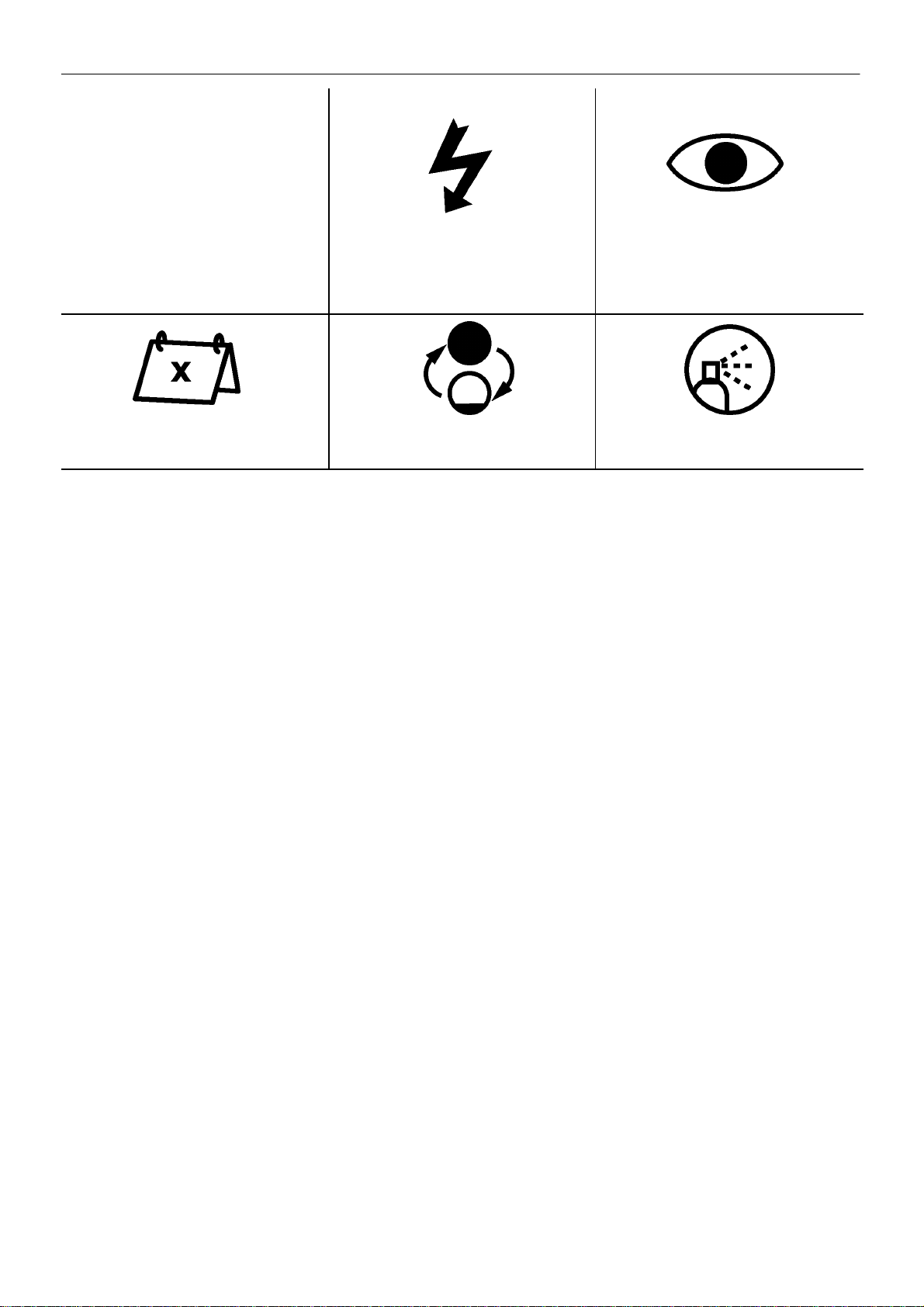
Use ULTRA–Plus Coolant only
Failure to use the specified coolant may
result in damage to the machine
DECALS 5
POWER INSPECT
Every X months, if sooner than required by
operating hours
CHANGE / REPLACE CLEAN
SSR UP6 15, UP6 20, UP6 25, UP6 30
Page 6
DECALS6
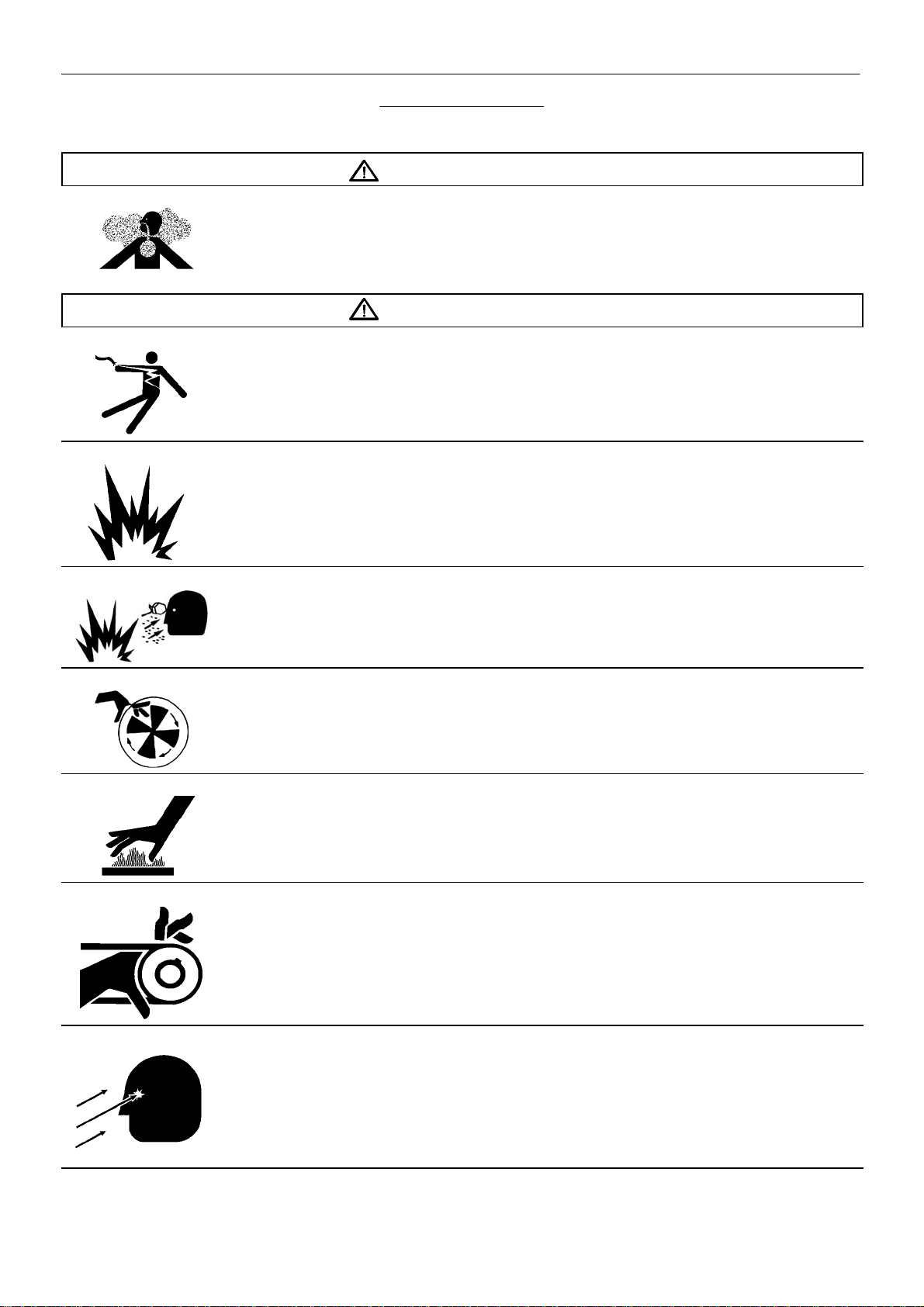
ANSI SYMBOLS
GRAPHIC FORM AND MEANING OF ANSI SYMBOLS
DANGER
INTAKE AIR. Can contain carbon monoxide or other contaminants. Will cause serious injury or death. Ingersoll–Rand
air compressors are not designed, intended or approved for breathing air. Compressed air should not be used for
breathing air applications unless treated in accordance with all applicable codes and regulations.
WARNING
HAZARDOUS VOLTAGE. Can cause serious injury or death. Disconnect power and bleed pressure from tank before
servicing. Lockout/Tagout machine. Compressor must be connected to properly grounded circuit. See Grounding
Instructions in manual. Do not operate compressor in wet conditions. Store indoors.
RISK OF FIRE OR EXPLOSION. Electrical arcing from compressor components can ignite flammable liquids and
vapors which can result in serious injury. Never operate the compressor near flammable liquids or vapors. If used to
spray flammable materials, keep compressor at least 20ft away from the spray area.
HIGH PRESSURE AIR. Rusted tanks can cause explosion and severe injury or death. Receiver under perssure.
Operator should relieve tank pressure before performing maintenance. In addition to automatic drain, operate manual
drain valve weekly. Manual drain valve located at bottom of the tank.
MOVING PARTS. Can cause serious injury. Do not operate with guards removed. Machine may start automatically.
Disconnect power before servicing. Lockout/Tagout machine.
HOT SURFACES. Can cause serious injury. Do not touch. Allow to cool before servicing. Do not touch hot
compressor or tubing.
EXPOSED MOVING BELTS AND SHEAVES.
Can cause severe injury or death.
Do not operate without guard in place. Disconnect power before servicing.
Lockout/Tagout machine.
SSR UP6 15, UP6 20, UP6 25, UP6 30
Air flow exhaust may contain flying debris.
Safety protection should be worn at all times.
Page 7
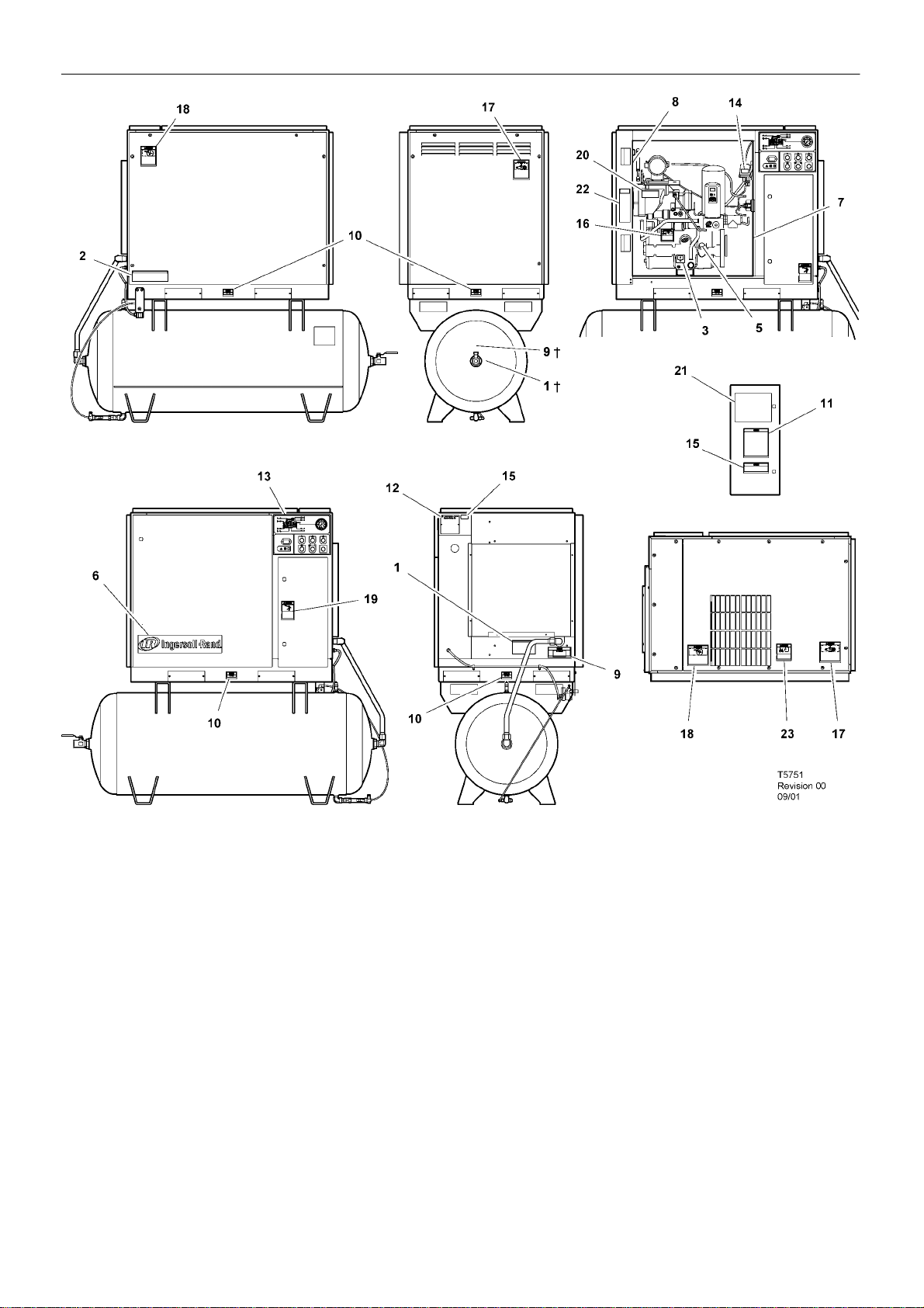
60 Hz Units
DECALS
INSIDE PACKAGE
7
VIEW BACK
VIEW FRONT
Item ccn Qty. Description Item ccn Qty. Description
1 32343519 1 Decal, warning contaminated air
Located near air discharge port of receiver
tank on tank mounted units
2 32343576 1 Decal, air receiver auto–drain
3 93166460 1 Decal, coolant drain
4 –
5 32343071 1 Decal, filler cap ultra plus
6 54499306 1 Decal, Ingersoll–Rand signature
horizontal 20“
7 32343063 1 Decal, maintenance parts
8 30286686 1 Decal, notice rotation
VIEW LEFT
INSIDE STARTER DOOR
VIEW TOP
VIEW RIGHT
9 32343543 1 Decal, notice air discharge
Located near air discharge port of receiver
tank on tank mounted units
10 93171262 4 Decal, notice lift here
11 32343493 1 Decal, overload setting IEC starter
12 SPEC 1 Specifications, compressor package
13 32342669 1 Decal, starter box
14 32017469 1 Decal, voltage 120/1/60
† Optional position
SSR UP6 15, UP6 20, UP6 25, UP6 30
Page 8
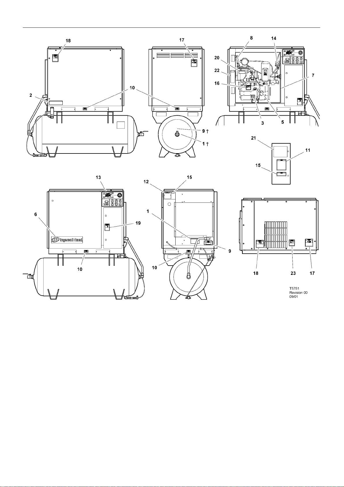
8
60 Hz Units
DECALS
INSIDE PACKAGE
VIEW BACK
VIEW FRONT
Item ccn Qty. Description Item ccn Qty. Description
15 32017436 1 Decal, voltage 230/3/60
32018475 1 Decal, voltage 200/3/60
32236481 1 Decal, voltage 380/3/60
32017444 1 Decal, voltage 460/3/60
32177305 1 Decal, voltage 575/3/60
16 32343527 1 Decal, warning high pressure
17 32343535 1 Decal, warning moving belts
18 32343550 1 Decal, warning exposed fan
VIEW LEFT
INSIDE STARTER DOOR
VIEW TOP
VIEW RIGHT
19 32343568 1 Decal, warning hazardous voltage
20 32343584 1 Decal, warning hot surface
21 32343634 1 Decal, wiring schematic DOL 60Hz
32343642 1 Decal, wiring schematic Star Delta 60Hz
22 32343907 1 Decal, lock and tag out
23 32343899 1 Decal, warning flying debris
† Optional position
SSR UP6 15, UP6 20, UP6 25, UP6 30
Page 9

SAFETY
9
DANGER!
Hazard that WILL cause DEATH, SEVERE INJURY or substantial
property damage if ignored. Instructions must be followed precisely to
avoid injury or death.
WARNING!
Hazard that CAN cause DEATH, SEVERE INJURY or substantial
property damage if ignored. Instructions which must be followed
precisely to avoid injury or death.
CAUTIONS!
Cautions call attention to instructions which must be followed
precisely to avoid damaging the product, process or its surroundings.
NOTES
Notes are used for supplementary information.
BREATHING AIR PRECAUTION
Ingersoll–Rand air compressors are not designed, intended or
approved for breathing air. Compressed air should not be used for
breathing air applications unless treated in accordance with all
applicable codes and regulations.
General Information
Ensure that the operator reads and understands the decals and
consults the manuals before maintenance or operation.
Ensure that the Operation and Maintenance manual is not removed
permanently from the machine.
Ensure that maintenance personnel are adequately trained,
competent and have read the Maintenance Manuals.
Do not point air nozzles or sprayers toward anyone.
Compressed air and electricity can be dangerous. Before
undertaking any work on the compressor, ensure that the electrical
supply has been isolated and the compressor has been relieved of all
pressure.
Wear eye protection when operating or servicing compressor.
All persons positioned near to operating machinery should be
equipped with hearing protection and given instructions on its use in
accordance with workplace safety legislation.
Make sure that all protective covers are in place and that the
canopy/doors are closed during operation.
The specification of this machine is such that the machine is not
suitable for use in flammable gas risk areas.
Installation of this compressor must be in accordance with
recognised electrical codes and any local Health and Safety Codes.
The use of plastic bowls on line filters can be hazardous. Their
safety can be affected by either synthetic lubricants, or the additives
used in mineral oils. Ingersoll –Rand recommends that only filters with
metal bowls should be used on a pressurised system.
Compressed air
Compressed air can be dangerous if incorrectly handled. Before
doing any work on the unit, ensure that all pressure is vented from the
system and that the machine cannot be started accidentally .
Ensure that the machine is operating at the rated pressure and that
the rated pressure is known to all relevant personnel.
All air pressure equipment installed in or connected to the machine
must have safe working pressure ratings of at least the machine rated
pressure.
If more than one compressor is connected to one common
downstream plant, effective isolation valves must be fitted and
controlled by work procedures, so that one machine cannot accidently
be pressurised / over pressurised by another.
Compressed air must not be used for a direct feed to any form of
breathing apparatus or mask.
The discharged air contains a very small percentage of compressor
lubricant and care should be taken to ensure that downstream
equipment is compatible.
If the discharged air is to be ultimately released into a confined
space, adequate ventilation must be provided.
When using compressed air always use appropriate personal
protective equipment.
All pressure containing parts, especially flexible hoses and their
couplings, must be regularly inspected, be free from defects and be
replaced according to the Manual instructions.
Compressed air can be dangerous if incorrectly handled. Before
doing any work on the unit, ensure that all pressure is vented from the
system and that the machine cannot be started accidentally .
Avoid bodily contact with compressed air .
All safety valves located in the separator tank must be checked
periodically for correct operation.
Do not over–pressurize the receiver tank or similar vessels beyond
design limits.
Do not use a receiver tank or similar vessels that fail to meet the
design requirements of the compressor. Contact your distributor for
assistance.
Do not drill into, weld or otherwise alter the receiver tank or similar
vessels.
Materials
The following substances are used in the manufacture of this
machine and may be hazardous to health if used incorrectly:
. preservative grease
. rust preventative
. compressor coolant
AVOID INGESTION, SKIN CONTACT AND INHALATION OF
FUMES
Transport
When loading or transporting machines ensure that the specified
lifting and tie down points are used.
Lifting equipment must be properly rated for the weight of the
compressor.
Do not work on or walk under the compressor while it is suspended.
Electrical
Keep all parts of the body and any hand–held tools or other
conductive objects, away from exposed live parts of the compressor
electrical system. Maintain dry footing, stand on insulating surfaces
and do not contact any other portion of the compressor when making
adjustments or repairs to exposed live parts of the compressor
electrical system.
WARNING
Any electrical connections or adjustments should only be
made by a suitably qualified electrician
Close and lock all access doors when the compressor is left
unattended.
Do not use extinguishers intended for Class A or Class B fires on
electrical fires. Use only extinguishers suitable for class BC or class
ABC fires.
Attempt repairs only in clean, dry, well lighted and ventilated areas.
Connect the compressor only to electrical systems that are
compatible with its electrical characteristics and that are within it’s rated
capacity.
Condensate disposal
As waste water regulations vary by country and region it is the
responsibility of the user to establish the limitations and regulations in
their particular area. Ingersoll–Rand and its associated distributors are
happy to advise and assist in these matters.
For further information, consult Material Data Sheets APDD 772 for
ULTRA–Plus Coolant.
SSR UP6 15, UP6 20, UP6 25, UP6 30
Page 10
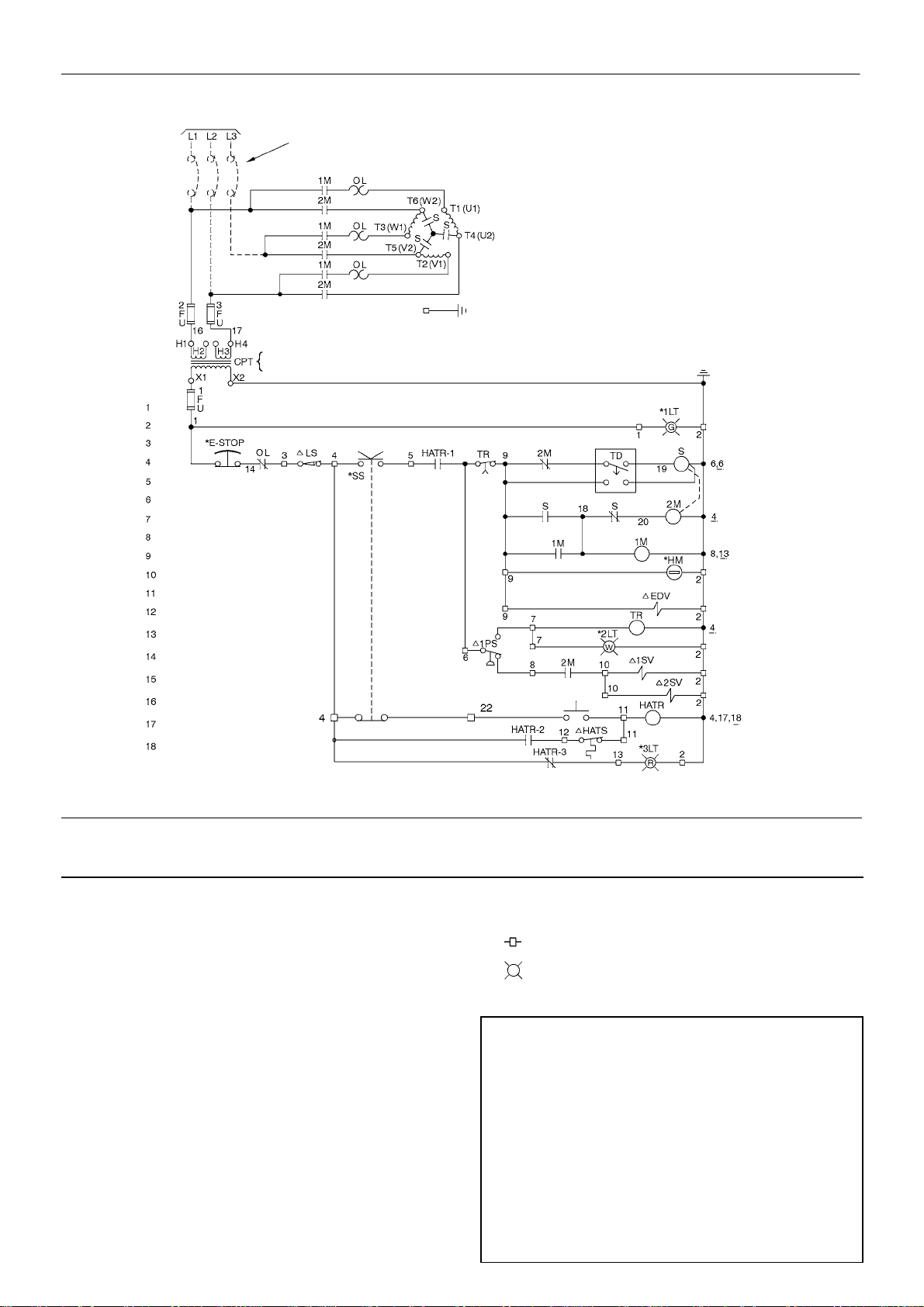
10
GENERAL INFORMATION
TO SUPPLY
SEE NOTES 1 & 2
SEE TRANSFORMER NAMEPLATE FOR
LINE
NUMBER
WIRING CONNECTION REQUIREMENTS.
* WYE (STAR) DELTA
MOTOR
(OPEN TRANSITION)
85583417
Rev. B
LEGEND
CPT
n EDV
*E–STOP
FU
*HM
HATR
n HATS
n LS
M
OL
n PS
*SS
S
n SV1
n SV2
Transformer, control
Valve, electric drain
Button, emergency stop
Fuse
Hourmeter
Relay, high air temperature
Switch, high air temperature
Switch, belt tension
Coil, motor starter
Overload, motor starter
Switch, pressure
Switch, selector
Coil, second motor starting
Valve, load solenoid N.C.
Valve, blow down solenoid N.O.
OFF ON
“POWER ON”
“STAND BY”
*RESET
“HI TEMP SHUTDOWN”
TD
TR
Relay , Delta starting
Relay, auto restart time delay (6 min)
Terminal points
*
Light, transformer type
NOTES
1. Approved fused disconnect or circuit breaker per code
requirements must be provided by customer.
2. Dashed lines represent wiring by customer.
3. Sizing of electrical components not supplied by Ingersoll–Rand is
the responsibility of the customer and should be done in
accordance with the information on the compressor data plate
and local electrical codes.
4. Unit will not restart automaticlly after power outage.
5. Circuit shown in normal position de–energized.
6. All wiring to be in accordance with local codes.
SSR UP6 15, UP6 20, UP6 25, UP6 30
Page 11
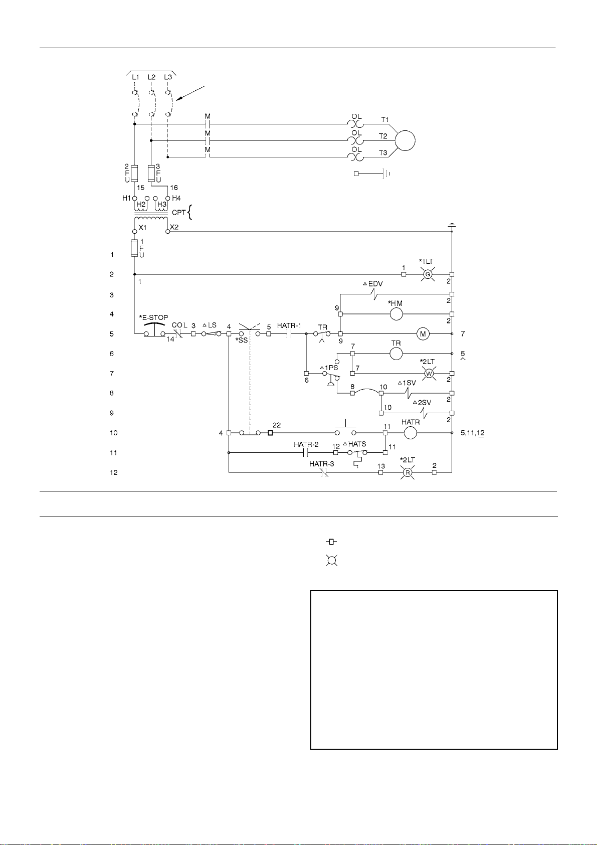
LINE
NUMBER
TO SUPPLY
SEE NOTES 1 & 2
SEE TRANSFORMER NAMEPLATE FOR
WIRING CONNECTION REQUIREMENTS.
OFF ON
GENERAL INFORMATION
COMPRESSOR
* MOTOR
“POWER ON”
11
85583409
Rev. B
LEGEND
CPT
n EDV
*E–STOP
FU
*HM
HATR
n HATS
n LS
M
OL
n PS
*SS
n SV1
n SV2
Transformer, control
Valve, electric drain
Button, emergency stop
Fuse
Hourmeter
Relay, high air temperature
Switch, high air temperature
Switch, belt tension
Coil, motor starter
Overload, motor starter
Switch, pressure
Switch, selector
Valve, load solenoid N.C.
Valve, blow down solenoid N.O.
“STAND BY”
*RESET
“HI TEMP SHUTDOWN”
TR
Relay, time delay (6 min)
Terminal points
*
Light, transformer type
NOTES
1. Approved fused disconnect or circuit breaker per code
requirements must be provided by customer.
2. Dashed lines represent wiring by customer.
3. Sizing of electrical components not supplied by Ingersoll–Rand is
the responsibility of the customer and should be done in
accordance with the information on the compressor data plate
and local electrical codes.
4. Unit will not restart automaticlly after power outage.
5. Circuit shown in normal position de–energized.
6. All wiring to be in accordance with local codes.
SSR UP6 15, UP6 20, UP6 25, UP6 30
Page 12
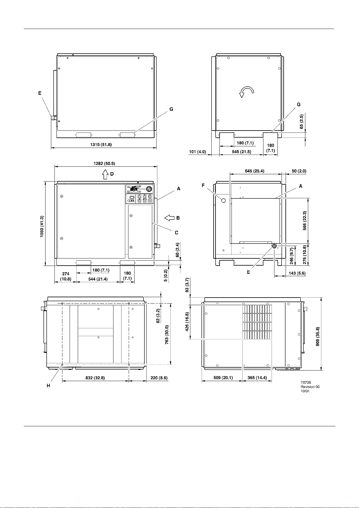
12
BASE MOUNTED UNITS
INSTALLATION / HANDLING
ROTATION
VIEW REAR
VIEW LEFT
VIEW FRONT
VIEW BOTTOM
KEY
A Pre filter
B Compressor and cooling air intake
C Starter box
D Cooling air exhaust
E 1.00” NPT air discharge
F Customer power inlet
VIEW RIGHT
VIEW TOP
G Fork lift openings
Fork lift hole covers must be installed after unit is in place to
reduce noise and ensure proper cooling of package)
H 4 slots 15 (0.6) x 25 (1.0)
See notes – Page 15
SSR UP6 15, UP6 20, UP6 25, UP6 30
Page 13
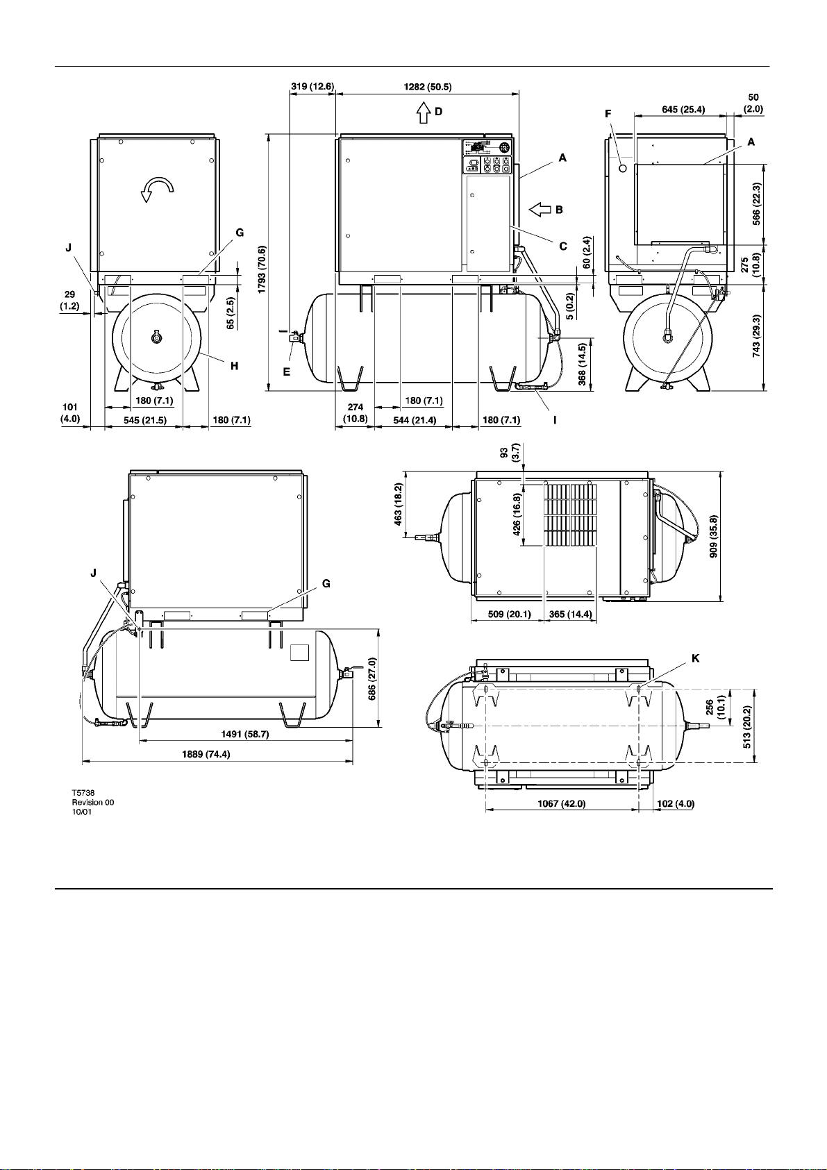
TANK MOUNTED (120 GALLON)
60 Hz UNITS
ROTATION
INSTALLATION / HANDLING
VIEW RIGHT
13
VIEW LEFT
VIEW FRONT
VIEW TOP
VIEW REAR
VIEW BOTTOM
KEY
A Pre filter
B Compressor and cooling air intake
C Starter box
D Cooling air exhaust
E 1.00” NPT air discharge
F Customer power inlet
G Fork lift openings
H Air receiver (120 gallons)
I Automatic drain valve
J 0.25 inch coondensate drain
K 4 slots 17 (0.7) x 44 (1.8)
See notes – Page 15
SSR UP6 15, UP6 20, UP6 25, UP6 30
Page 14
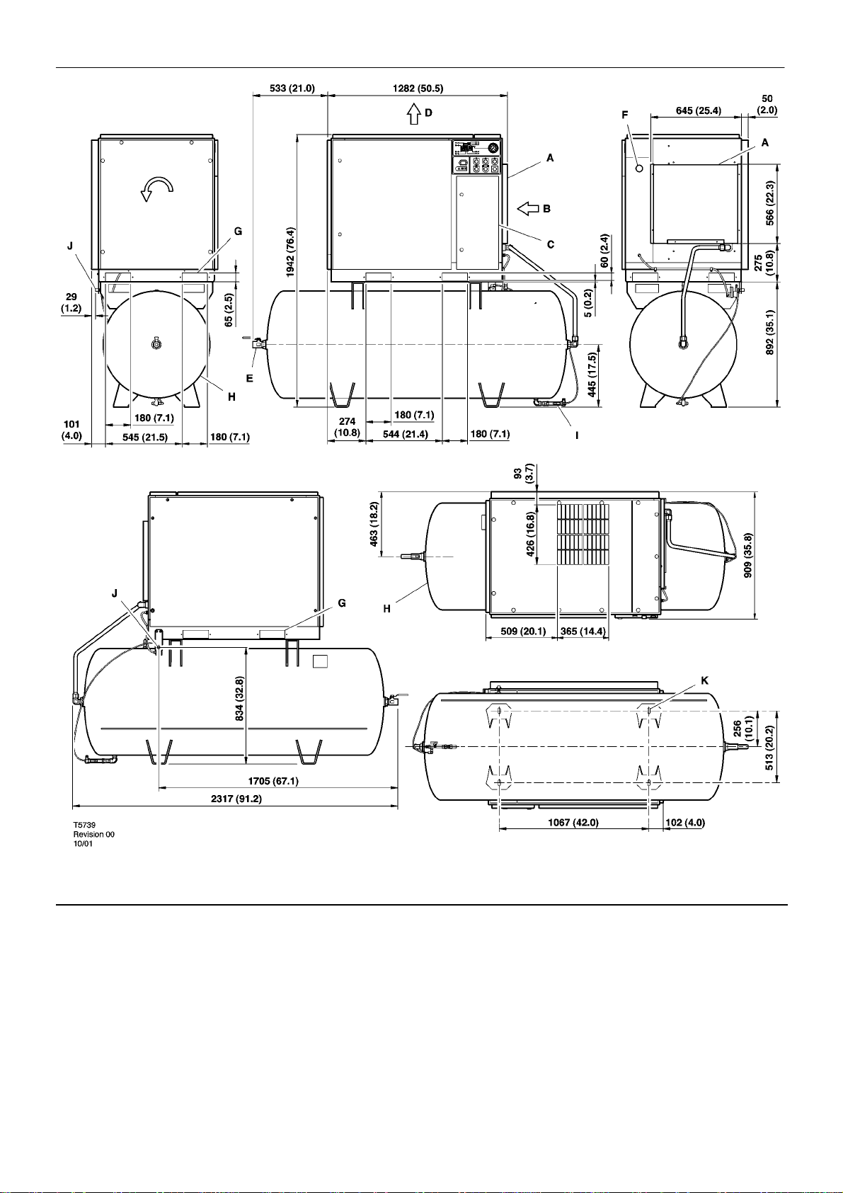
14
TANK MOUNTED (240 GALLON)
60 Hz UNITS
INSTALLATION / HANDLING
ROTATION
VIEW RIGHT
VIEW LEFT
VIEW FRONT
VIEW TOP
VIEW REAR
VIEW BOTTOM
KEY
A Pre filter
B Compressor and cooling air intake
C Starter box
D Cooling air exhaust
E 1.00” NPT air discharge
F Customer power inlet
G Fork lift openings
SSR UP6 15, UP6 20, UP6 25, UP6 30
H Air receiver (240 gallons)
I Automatic drain valve
J 0.25 inch coondensate drain
K 4 slots 17 (0.7) x 44 (1.8)
See notes – Page 15
Page 15

NOTES
INSTALLATION / HANDLING
15
1. Coolant (lubricant) fill quantity (approximate) 13 litres (3.4 gallons).
2. Recommended clearance in front of control panel door 1067 mm
(42 inches) or minimum as required by the latest national electrical
codes (NEC) or applicable local codes.
3. Recommended clearances on left and right sides 914mm (36
inches).
4. Minimum recommended clearance for the rear of the compressor
is to be 152mm (6 inches).
5. External piping shall not exert any unresolved moments or forces
on the unit. Use pipe size as large or larger at discharge connection.
6. There should be no plastic or pvc piping attached to this unit or used
for any lines downstream.
7. Any field installed ducting to and from the compressor cannot add
more than 12.5mm( 1/2”) water gauge total air resistance.
8. Do not pipe into a common header with a reciprocating compressor,
unless the reciprocating compressor utilizes a discharge pulsation
damper.
9. Sizing of electrical components not supplied by Ingersoll Rand is the
responsibility of the customer and should be done in accordance with
the information on the compressor data plate and national and local
electrical codes.
NOTE
All dimensions are in millimetres (inches) unless otherwise stated.
Ensure that the correct fork lift truck slots or marked lifting points are
used whenever the machine is lifted or transported.
UNPACKING
The compressor will normally be delivered with a polythene cover.
If a knife has to be used to remove this cover ensure that the exterior
paintwork of the compressor is not damaged.
Ensure that all transport and packing materials are discarded in a
manner prescribed by local codes.
NOTE
Units are shipped with transit locking bolt in place. Prior to running
the unit the shipping bolt must be removed and the belt tension
checked. Loosen, remove and discard 10mm shipping bolt. For belt
tensioning procedure refer to Maintenance section.
SSR UP6 15, UP6 20, UP6 25, UP6 30
Page 16
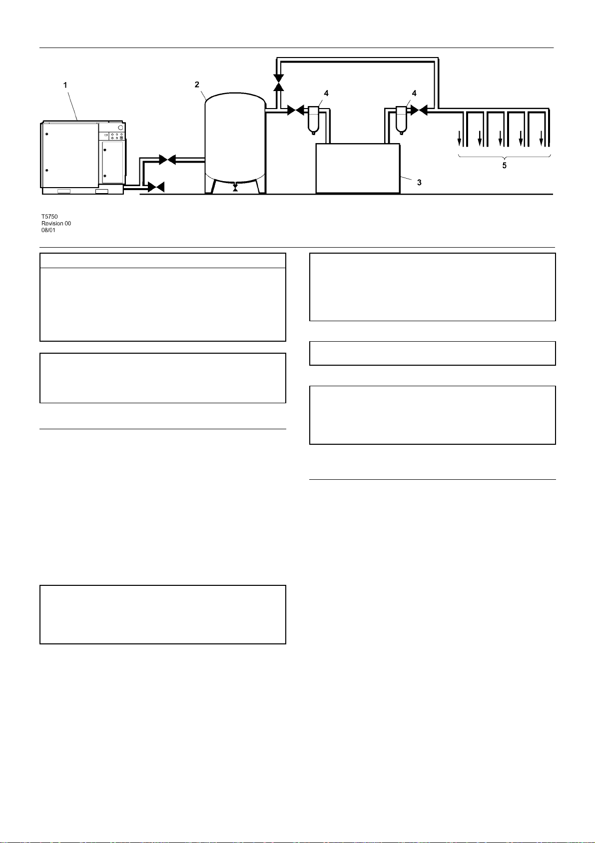
16
INSTALLATION / HANDLING
KEY
1. Compressor
2. Air Receiver
3. Air Dryer
4. Compressed air filters
5. System demand points
NOTE
Items [2] to [5] are optional or may be existing items of plant. Refer
to your Ingersoll–Rand distributor / representative for specific
recommendations.
LOCATION IN THE PLANT
The compressor can be installed on any level floor capable of
supporting it. A dry, well ventilated area where the atmosphere is clean
is recommended. A minimum of 150mm (6 inches) should be left at the
rear and 1m (3ft) at the sides of the machine for adequate service
access and ventilation.
Adequate clearance needs to be allowed around and above the
machine to permit safe access for specified maintenance tasks.
Ensure that the machine is positioned securely and on a stable
foundation. Any risk of movement should be removed by suitable
means, especially to avoid strain on any rigid discharge piping.
CAUTION
The use of plastic bowls on line filters and other plastic air line
components can be hazardous. Their safety can be affected by either
synthetic coolants or the additives used in mineral oils. Ingersoll –Rand
recommends that only filters with metal bowls should be used on any
pressurised system.
CAUTION
Before starting machine remove shipping bolt and discard
CAUTION
The standard compressor unit is not suitable for operation in
temperatures liable to cause freezing as Condensate water is liable to
be produced in the after cooler and receiver where fitted.
Refer to your Ingersoll–Rand distributor for further information
DISCHARGE PIPING
Discharge piping should be at least as large as the discharge
connection o f the compressor. All piping and fittings should be suitably
rated for the discharge pressure.
It is essential when installing a new compressor [1], to review the
total air system. This is to ensure a safe and effective total system. One
item which should be considered is liquid carryover. Installation of air
dryers [3] is always good practice since properly selected and installed
they can reduce any liquid carryover to zero.
CAUTION
Screw type compressors [1] should not be installed in air systems
with reciprocating compressors without means of isolation such as a
common receiver tank. It is recommended that both types of
compressor be piped to a common receiver using individual air lines.
SSR UP6 15, UP6 20, UP6 25, UP6 30
It is good practice to locate an isolation valve close to the
compressor and to install line filters [4].
It is a requirement for air dryers covered under Aircare that correctly
sized Ingersoll–Rand pre and afterfilters are installed.
Page 17
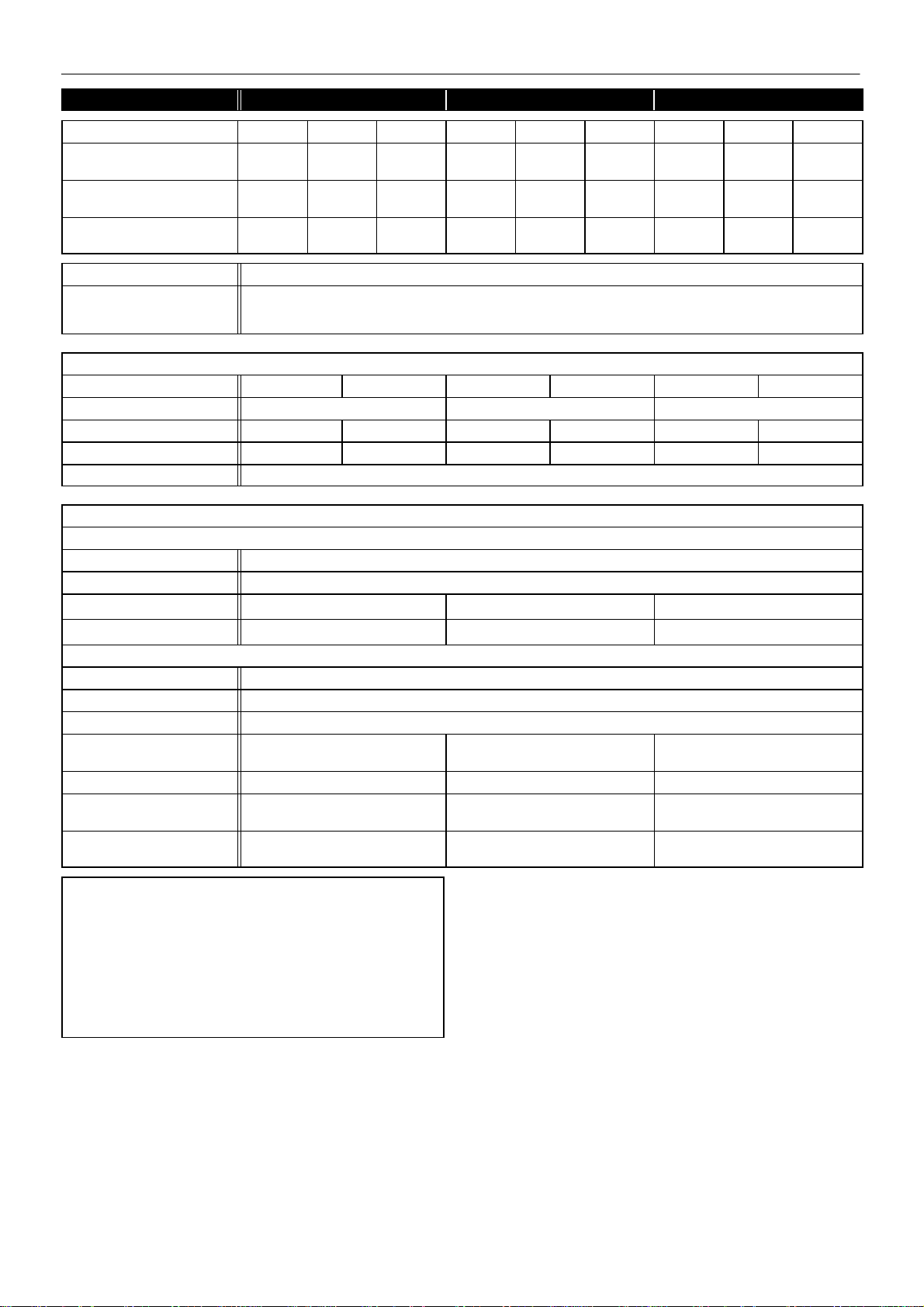
INSTALLATION / HANDLING
60Hz UP6 20 UP6 25 UP6 30
COMPRESSOR 125 150 200 125 150 200 125 150 200
Maximum operating pressure
PSIG (bar)
Factory set reload pressure
PSIG (bar)
Flow rate
CFM (m3/MIN)
Max. airend discharge temp. 228_F (109_C)
Ambient operating
temperature
min. → max.
MOTOR
Motor enclosure ODP TEFC ODP TEFC ODP TEFC
Nominal power 20HP 25HP 30HP
Speed 1760 RPM 1770 RPM 1760 RPM 1770 RPM 1770 RPM 1770 RPM
Frame 256TZ 160 L 284TZ 180 M 286TZ 180 L
Insulation class F
125
(8.62)
115
(7.93)
83
(2.35)
150
(10.34)
140
(9.66)
75
(2.12)
200
(13.79)
190
(13.10)
58
(1.64)
125
(8.62)
115
(7.93)
102
(2.89)
35_F(+2_C ) → 104_F(+40_C)
150
(10.34)
140
(9.66)
92
(2.61)
200
(13.79)
190
(13.10)
(2.12)
75
125
(8.62)
115
(7.93)
125
(3.54)
150
(10.34)
140
(9.66)
112
(3.17)
17
200
(13.79)
190
(13.10)
92
(2.61)
COOLING SYSTEM
Air cooled
Cooling air flow 2100 ft3/min
Maximum ∆P in air ducts
Compressed air outlet ∆T
Cooling air outlet ∆T
GENERAL DATA
Residual coolant content 3ppm (3 mg/m
Separator vessel capacity 4.5 gallons (17 liters)
Coolant capacity 3.4 gallons (13 liters)
Sound pressure level to
CAGI–PNEUROP
Weight – base mount unit 1183 lbs (538 kg) 1203 lbs (547 kg) 1290 lbs (586 kg)
Weight – 120 gallon Receiver
mounted
Weight – 240 gallon Receiver
mounted
CAUTION
230/460 Dual voltage machines are fitted with a decal to advise the
correct voltage as connected from the factory.
There is a decal fitted to the starter door describing the procedure
to change the connections for the alternative voltage
12_F (7_C) 18_F (10_C) 26_F (14.5_C)
24_F (13.5_C) 31_F (17_C) 36_F (20_C)
68 dB(A) 69 dB(A) 69 dB(A)
1510 lbs (685 kg) 1530 lbs (694 kg) 1616 lbs (733 kg)
1779 lbs (807 kg) 1799 lbs (816 kg) 1885 lbs (855 kg)
1
/2 inWg (12.7mmH2O)
3)
Rewiring should only be effected by a competent Electrician.
SSR UP6 15, UP6 20, UP6 25, UP6 30
Page 18
18
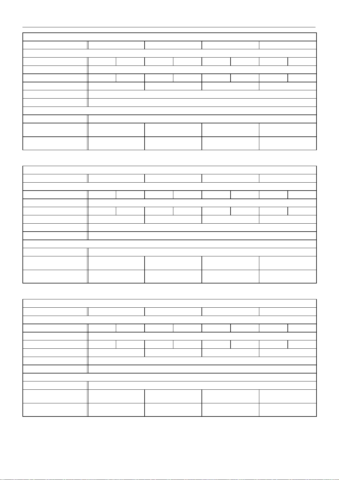
ELECTRICAL DATA – ALL UNITS SSR UP6–20
Standard voltage 200V 230V 460V 575V
Drive motor
Motor enclosure ODP TEFC ODP TEFC ODP TEFC ODP TEFC
Power 20HP
Full load current (maximum) 65A 63.1A 56.4A 54.8A 28.2A 27.5A 22.6A 22A
Starting current DOL (STAR) 336 (150) 292 (130) 146 (65) 117 (52)
Starting time DOL (Star Delta) 3–5 Sec ( 7–10 Sec)
Starts per hour (maximum) 6
ELECTRICAL DATA DOL / Star Delta
Control voltage 120VAC
Minimum fuse rating
See note 1
Minimum wire size AWG
See note 2
ELECTRICAL DATA – ALL UNITS SSR UP6–25
Standard voltage 200V 230V 460V 575V
Drive motor
Motor enclosure ODP TEFC ODP TEFC ODP TEFC ODP TEFC
Power 25HP
Full load current (maximum) 76.6A 76.5A 66.6A 66.5A 33.3A 33.3A 26.6A 26.6A
Starting current DOL (STAR) 411.7 (182.2) 358 (158.4) 179 (79.2) 143.2 (63.4)
Starting time DOL (Star Delta) 3–5 Sec ( 7–10 Sec)
Starts per hour (maximum) 6
ELECTRICAL DATA DOL / Star Delta
Control voltage 120VAC
Minimum fuse rating
See note 1
Minimum wire size AWG
See note 2
INSTALLATION / HANDLING
90A 80A 40A 35A
4 4 10 10
125A 100A 50A 40A
3 3 8 10
ELECTRICAL DATA – ALL UNITS SSR UP6–30
Standard voltage 200V 230V 460V 575V
Drive motor
Motor enclosure ODP TEFC ODP TEFC ODP TEFC ODP TEFC
Power 30HP
Full load current (maximum) 91.3A 91.9A 79.3A 79.9A 39.7A 40A 31.7A 32A
Starting current DOL (STAR) 500 (216.7) 434 (188.4) 217 (94.2) 169 (75.4)
Starting time DOL (Star Delta) 3–5 Sec ( 7–10 Sec)
Starts per hour (maximum) 6
ELECTRICAL DATA DOL / Star Delta
Control voltage 120VAC
Minimum fuse rating
See note 1
Minimum wire size AWG
See note 2
1. If a circuit breaker is selected it should only be a magnetic trip type,
set above the anticipated starting current of the machine, but below the
maximum prospective fault current for the circuit. The circuit breaker
or fuseable disconnect must be capable of breaking the prospective
fault current at its terminals.
2. PVC/PVC Type Calculated using the following conditions:
150A 125A 60A 50A
1 2 6 8
i) PVC insulated cable, armoured, copper conductors.
ii) Cable clipped to a wall, in free air.
iii) Ambient temperature of 40_C (104_F).
iv) 20m (65ft) cable run.
v) Volt drop limited to –10% during starting, –4% during normal
running.
vi) Protected by the circuit breaker listed above.
SSR UP6 15, UP6 20, UP6 25, UP6 30
Page 19

INSTALLATION / HANDLING
19
If there are any deviations from the above, or special regulations
apply, the installation must be planned by a competent, qualified
engineer.
NOTE
All data applies to standard product only.
ELECTRICAL DATA
An independent electrical isolator or disconnect should be installed
adjacent to the compressor.
Feeder cables/wires should be sized by the customer/electrical
contractor to ensure that the circuit is balanced and not overloaded by
other electrical equipment. The length of wiring from a suitable
electrical feed point is critical as voltage drops may impair the
performance of the compressor.
Feeder cables / wires connections to isolator or disconnect should
be tight and clean.
The applied voltage must be compatible with the motor and
compressor data plate ratings.
The control circuit transformer has different voltage tappings.
Ensure that these are set for the specific applied voltage prior to
starting.
CAUTION
Never test the insulation resistance of any part of the machines
electrical circuits, including the motor without completely disconnecting
the electronic controller (where fitted).
CAUTION
Ensure that the motor rotates in the correct direction as indicated b y
direction arrows, and on drawing.
SSR UP6 15, UP6 20, UP6 25, UP6 30
Page 20

20
OPERATING INSTRUCTIONS
GENERAL OPERATION
The compressor is an electric motor driven, single stage screw
compressor, complete with accessories piped, wired and baseplate
mounted. It is a totally self contained air compressor package.
The standard compressor is designed to operate in an ambient
range o f 2 _C to 40_C (35.6_F – 104_F) with a special option package
available to operate in ambient temperatures ranges from 2_C up to
50_C (35.6_F up to 124_F). The maximum temperature is applicable
to either version up to a maximum elevation of 1000m (3280ft) above
sea level. Above this altitude significant reduction in maximum
allowable ambient temperature is required.
Compression in the screw type air compressor is created by the
meshing o f two (male & female) helical rotors.
The air/coolant mixture discharges from the compressor into the
separation system. This system removes all but a few PPM of the
coolant from the discharge air. The coolant is returned to the cooling
system and the air passes through the aftercooler and out of the
compressor.
Cooling air is moved through the coolers by the cooling fan and
discharged from the machine.
CAUTION
Cooling air is drawn in at the end of the machine package passing
through the filter and cooler before being discharged from the top of the
machine. Care should be taken to avoid blocking the airflow, or causing
any restriction in excess of the maximum backpressure allowed for
ducting.
Do not direct the airflow at face or eyes.
The power transmission from the drive motor to the airend male
rotor is b y pulley and belts. The constant auto tensioning system, using
airend mass torque and gas arm, ensures that the belts are always
under the correct tension, eliminating the need for adjustment and
maximizing the life of the belts.
By cooling the discharge air, much of the water vapour naturally
contained in the air is condensed and may be drained from the
downstream piping and equipment.
The coolant system consists of a sump, cooler, thermostatic valve
and a filter. When the unit is operating, the coolant is pressurized and
forced to the compressor bearings.
The compressor load control system is automatic on–off line. The
compressor will operate to maintain a set discharge line pressure and
is provided with an auto restart system for use in plants where the air
demand varies sufficiently to allow a compressor to shut down and
save power. Significant system volume will assist this and is
recommended.
WARNING
When the unit stops running as the result of low air demand,
normally indicated by auto restart light, it may restart and return to load
at any time.
Safety of operation is provided as the compressor will shut down if
excessive temperatures or electrical overload conditions should occur .
CAUTION
This unit is not designed or intended to operate when contaminated
with silicone. Lubricants, greases or other items containing silicone
should not be used on this unit.
SSR UP6 15, UP6 20, UP6 25, UP6 30
Page 21
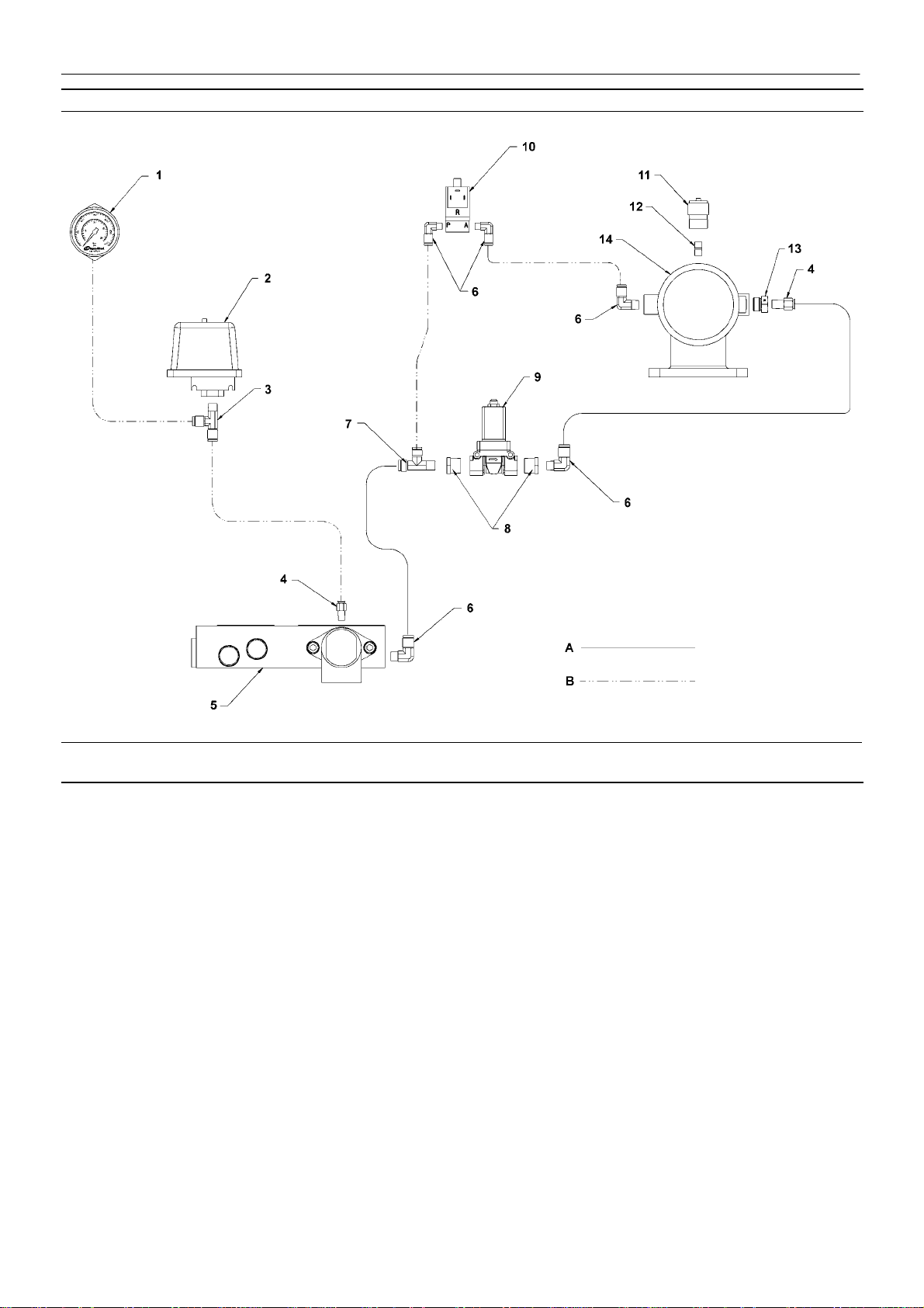
ELECTRO–PNEUMATIC CONTROL AND INSTRUMENTATION
OPERATING INSTRUCTIONS
21
KEY
1. Pressure gauge
2. Pressure switch
3. Tee
4. Connector
5. Combination block
6. Elbow
7. Tee, male run
8. Reducer bushing
9. Blow down solenoid valve
10.Load solenoid valve
11.Indicator air filter
12.Nipple
13.Adaptor
14.Intake valve assembly
NOTES:
A. Tubing 3/8 inch
B. Tubing 1/4 inch
SSR UP6 15, UP6 20, UP6 25, UP6 30
Page 22

22
OPERATING INSTRUCTIONS
1. PRESSURE GAUGE
Indicates the system pressure.
WARNING
DO NOT operate the compressor at discharge pressures over the
rated pressure.
2. HOURMETER
Records the total running time of the compressor.
3. EMERGENCY STOP
When depressed will stop the compressor immediately. The ’Power
on’ indicator will remain illuminated. The emergency stop button must
be released before the compressor can be restarted.
4. START/STOP
When switched to the ON position will cause the unit to start and run
in a loaded condition if there is a demand for air. If there is no demand,
the machine will run unloaded before stopping automatically.
When switched to the OFF position, will unload and stop the unit if
it is running. If the unit is in auto restart it will prevent the unit from
re–starting when there is a demand for air.
5. POWER ON (Green)
Indicates the presence of control voltage at the controller.
6. AUTO RESTART (White)
Will illuminate when the machine has shut-down due to low air
demand. The machine will restart and load automatically as soon as the
demand for air returns.
PRIOR TO STARTING
1. Make visual check of the machine, ensure that all guards secure
and that nothing is obstructing the proper ventilation of, or free access
to the machine.
2. Check coolant level. Add if necessary.
3. Make sure main discharge valve is open.
4. Turn on electrical isolator or disconnect. The Power on (5) indicator
will light, indicating that line and control voltages are available.
5. Check direction of rotation at initial start or following interruption in
power supply.
WARNING
Make sure that all protective covers are in place.
Cooling air flow exhaust may contain flying debris. Safety
Protection should be worn at all times to avoid injury.
STARTING
1. Push the RESET button (8). The fault indicator (7) will extinguish.
Switch the ON/OFF switch (4) to the ON position. The compressor will
start and then load automatically.
7. FAULT / HIGH AIR TEMPERATURE ALARM (Red)
Turn off electrical Isolator or disconnect. Investigate cause of fault.
8. RESET BUTTON
Press button to reset the control system following compressor trip.
SSR UP6 15, UP6 20, UP6 25, UP6 30
Page 23

NORMAL/EMERGENCY STOPPING
1. Switch the ON/OFF switch (4) to the OFF position. The compressor
will unload and stop.
2. Press EMERGENCY STOP button (3) and the compressor will stop
immediately.
3. Turn off electrical isolator or disconnect.
CAUTION
After shutdown never allow unit to stand idle with pressure in
receiver/separator system.
OPERATING INSTRUCTIONS
23
SSR UP6 15, UP6 20, UP6 25, UP6 30
Page 24
24
MAINTENANCE
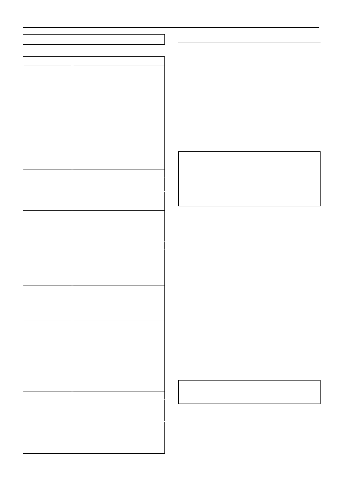
SSR UP Series Maintenance Schedule
PERIOD MAINTENANCE
Each 24 hours
operation
Visual check of
machine for any
leaks, dust build up
or unusual noise or
vibration
When compressor is
receiver mounted
Visual check
condition o f package
pre–filter
If the air filter
indicator shows red
before the 3000
hour/1 year change
out period
First 150 hours Change the coolant filter.
Each month or 100
hours
Each year or
3000 hours
Pressure vessel
inspection
frequency may be
otherwise defined by
local or national
legislation.
Every two years or
9000 hours
Check the coolant level and replenish if
necessary.
Report immediately, contact Ingersoll–Rand
authorized distributor for assistance if in
doubt
Drain air receiver of condensate, or check
that automatic drain is operating
Blow clean if needed
Check the Condition of filter. Change the air
filter if needed. Dusty environments require
more frequent replacement or, optional high
dust filter
Remove and clean package pre–filter,
replace if needed
Check the cooler(s) for build up of foreign
matter. Clean if necessary by blowing out
with air or by pressure washing.
Check the operation of the high temperature
protection switch (109_C).
Change the coolant filter.
Change the separator cartridge.
Change the Air Filter element.
Change the package pre–filter.
Visual Check of Drive Belts and tensioning
gas spring.
Remove the safety valve from the
compressor, inspect and re–calibrate.
Separator vessel and air receiver when
fitted.
Fully inspect all external surfaces, and
fittings. Report any excessive corrosion,
mechanical or impact damage, leakage or
other deterioration.
Change drive belt and gas spring.
Replace the Ultra Plus Coolant at whichever
interval occurs first.
Check and replace all items included within
3000 hour service
Fit the following reconditioning parts as
appropriate:
ROUTINE MAINTENANCE
This section refers to the various components which require
periodic maintenance and replacement.
. It should be noted that the intervals between service requirement
may be significantly reduced as a consequence of poor operating
environment. This would include effects of atmospheric contamination
and extremes of temperature.
The SERVICE/MAINTENANCE CHART indicates the various
components’ descriptions and the intervals when maintenance has to
take place. Oil capacities, etc., can be found in the GENERAL
INFORMATION section of this manual.
Compressed air can be dangerous if incorrectly handled. Before
doing any work on the unit, ensure that all pressure is vented from the
system and that the machine cannot be started accidentally .
CAUTION: Before beginning any work on the compressor, open,
lock and tag the main electrical disconnect and close the isolation
valve on the compressor discharge. Vent pressure from the unit
by slowly unscrewing the coolant fill cap one turn. Unscrewing
the fill cap opens a vent hole, drilled in the cap, allowing pressure
to release to atmosphere. Do not remove the fill cap until all
pressure has vented from the unit. Also vent piping by slightly
opening the drain valve. When opening the drain valve or the
coolant fill cap, stand clear of the valve discharge and wear
appropriate eye protection.
Ensure that maintenance personnel are properly trained,
competent and have read the Maintenance Manuals.
Prior to attempting any maintenance work, ensure that:–
. all air pressure is fully discharged and isolated from the system. If
the automatic blowdown valve is used for this purpose, then allow
enough time for it to complete the operation.
. the machine cannot be started accidently or otherwise.
. all residual electrical power sources (mains and battery) are
isolated.
Prior to opening or removing panels or covers to work inside
a machine, ensure that:–
. anyone entering the machine is aware of the reduced level of
protection and the additional hazards, including hot surfaces and
intermittently moving parts.
. the machine cannot be started accidently or otherwise.
Prior to attempting any maintenance work on a running
machine, ensure that:–
Solenoid valve kit
Inlet valve kit
Minimum Pressure valve kit
Every 4 years or Replace all hoses.
18000 hours
6 years/18000 hours
or as defined by
local or national
legislation.
SSR UP6 15, UP6 20, UP6 25, UP6 30
Strip, clean and re–Grease motor bearings
of ODP motors.
Replace sealed bearing on IP55 motors.
Fit replacement electrical contactor tips.
Separator tank.
Remove the cover plate and any necessary
fittings. Clean the interior thoroughly and
inspect all internal surfaces.
DANGER
Only properly trained and competent persons should undertake any
maintanence tasks with the compressor running or with electrical
power connected.
. the work carried out is limited to only those tasks which require the
machine t o run.
. the work carried out with safety protection devices disabled or
removed i s limited to only those tasks which require the machine to be
running with safety protection devices disabled or removed.
Page 25

MAINTENANCE
25
. all hazards present are known (e.g. pressurised components,
electrically live components, removed panels, covers and guards,
extreme temperatures, inflow and outflow of air, intermittently moving
parts, safety valve discharge etc.).
. appropriate personal protective equipment is worn.
. loose clothing, jewellery, long hair etc. is made safe.
. warning signs indicating that Maintenance Work is in Progress are
posted in a position that can be clearly seen.
Upon completion of maintenance tasks and prior to returning
the machine into service, ensure that:–
. the machine is suitably tested.
. all guards and safety protection devices are refitted and correctly
working.
. all panels are replaced, canopy and doors closed.
. hazardous materials are effectively contained and disposed of.
. hazardous materials are effectively contained and disposed of in a
manner compliant with local or National environmental protection
codes.
WARNING
Do not under any circumstances open any drain valve or remove
components from the compressor without first ensuring that the
compressor is FULLY SHUT– DOWN, power isolated and all air
pressure relieved from the system.
8. Refill the machine following the ”top up coolant” procedure above.
After initial fill, to purge any airlocks, the machine should be run for a
few minutes cycling between load and no load, before checking that the
level is correct.
9. Replace and tighten oil fill cap.
COOLANT FILTER CHANGE PROCEDURE
1. Stop the machine, electrically isolate and vent all trapped pressure.
2. Loosen filter with the correct tool.
3. Remove the filter from the housing.
4. Place the old filter in a sealed bag and dispose of in a safe way.
5. Clean the mating face of the housing taking care to avoid any
particles entering the machine.
6. Remove the new Ingersoll–Rand replacement filter from its
protective package.
7. Apply a small amount of lubricant to the filter seal.
8. Screw the new filter down until the seal makes contact with the
housing, then hand tighten a further half turn.
TOP UP COOLANT PROCEDURE
The reservoir is designed to prevent overfill. With warm unit stopped
in the normal way, the sight tube level should be within 15mm (0.6in)
of the top of the green strip. The level should not drop beyond the
bottom o f the sight tube when running with a steady load.
CAUTION
Ensure tha t n e w SSR ULTRA–PLUS coolant is used. Failure to do
so will void manufacturers warranty.
COOLANT CHANGE PROCEDURE
It is better to drain the coolant immediately after the compressor has
been operating as the liquid will drain more easily and any contaminant
will still be in suspension.
1. Stop the machine, electrically isolate and vent all trapped pressure.
2. Place a suitable container close to the drain valve.
3. Slowly remove fill/vent cap.
4. Remove plug from drain valve.
5. Open the drain valve and drain coolant into container.
9. Start the compressor and check for leaks.
AIR FILTER ELEMENT CHANGE PROCEDURE
1. Stop the machine, electrically isolate and vent all trapped pressure.
2. Unscrew the retaining cap and withdraw the old element.
3. Fit the new element.
4. Replace the retaining cap.
6. Close the drain valve.
7. Replace plug in drain valve.
SSR UP6 15, UP6 20, UP6 25, UP6 30
Page 26

26
MAINTENANCE
SEPARATOR CARTRIDGE CHANGE PROCEDURE
1. Stop the machine, electrically isolate and vent all trapped pressure.
2. Loosen separator cartridge with the correct tool.
3. Remove the cartridge from the housing; place it in a sealed bag and
dispose of it safely.
4. Clean the mating face of the housing.
5. Remove the new Ingersoll–Rand replacement cartridge from its
protective package.
6. Apply a small amount of lubricant to the cartridge seal.
7. Screw the new cartridge down until the seal makes contact with the
housing, then hand tighten a further half turn.
8. Start the compressor and check for leaks.
CAUTION
This unit is not designed or intended to operate when contaminated
with silicone. Lubricants, greases or other items containing silicone
should not be used on this unit.
COOLER CLEANING PROCEDURE
1. Stop the machine, electrically isolate and vent all trapped pressure.
2. Remove the top cover to obtain access to the cooler.
3. Clean the cooler.
4. Rebuild in reverse order.
SSR UP6 15, UP6 20, UP6 25, UP6 30
Page 27
MAINTENANCE
27
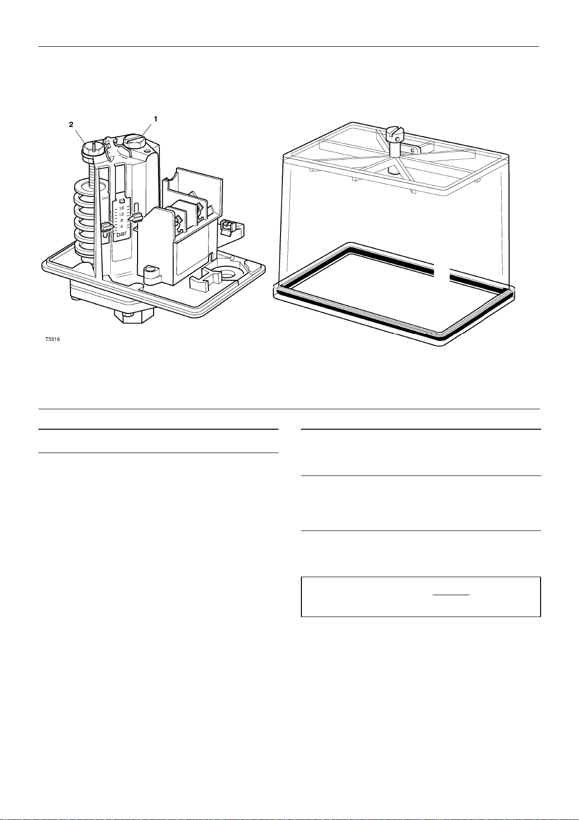
SETTING THE PRESSURE SWITCH (1PS)
TO CHECK THE MAXIMUM DISCHARGE PRESSURE
(Pressure switch upper trip point)
Slowly close the isolation valve located adjacent to the compressor.
Observe the rise in pressure and ensure that the pressure switch
opens (and unloads the compressor) at the correct Maximum
discharge pressure.
The maximum discharge pressure is shown on the machine data plate.
DO NOT exceed these figures.
TO CHECK THE LOWER SET POINT
Observe the line pressure fall and note the point at which the
pressure switch closes (and loads the compressor).
TO ADJUST THE UPPER SET POINT
Remove the transparent cover and turn the adjuster [1]. The red
pointer will move. Turn the adjuster anti–clockwise to increase the set
point or clockwise to decrease it.
TO ADJUST THE LOWER SET POINT
Remove the transparent cover and turn the adjuster [2]. The green
pointer will move. Turn the adjuster anti–clockwise to increase the set
point or clockwise to decrease it.
NOTE
The pressure switch scale is a guide only. Use the machine
pressure gauge to verify the upper and lower set points.
SSR UP6 15, UP6 20, UP6 25, UP6 30
Page 28
28
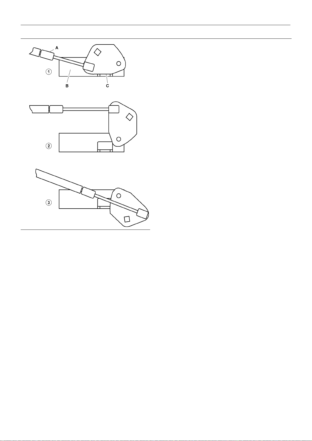
BELT CHANGE / GAS STRUT CHANGE PROCEDURE
MAINTENANCE
1. Stop the machine, electrically isolate and vent all trapped pressure.
2. Remove the side cover from the machine.
1
3. Fit a
airend (access from front door). Turn clockwise 1/4 turn to Position 2 to
release gas strut tension on the belts.
4. Using a small screwdriver under the spring clip, ease the ball ends
off the spherical studs at the ends of the gas strut.
5. Replace the gas strut and the studs at the same time by removing
and replacing the studs then pushing the new gas strut firmly onto the
studs until it clicks into place.
6. Turn the tension cam clockwise
support the airend. Place a block of wood or similar under the separator
tank for support.
7. Replace the belts from the left side of the machine.
/2” square drive wrench in the tension cam located above the
1
/4 turn to Position 3 to raise and
A. Gas strut.
B. Support bracket (part of pivoted assembly).
C. Over–center linkage.
8. Turn the tension cam counter–clockwise
tension the gas strut.
9. Spin the drive to check alignment of the belt ribs on the pulleys
(sheaves).
1
turn to position 1 to
/2
SSR UP6 15, UP6 20, UP6 25, UP6 30
Page 29
TROUBLE SHOOTING
29
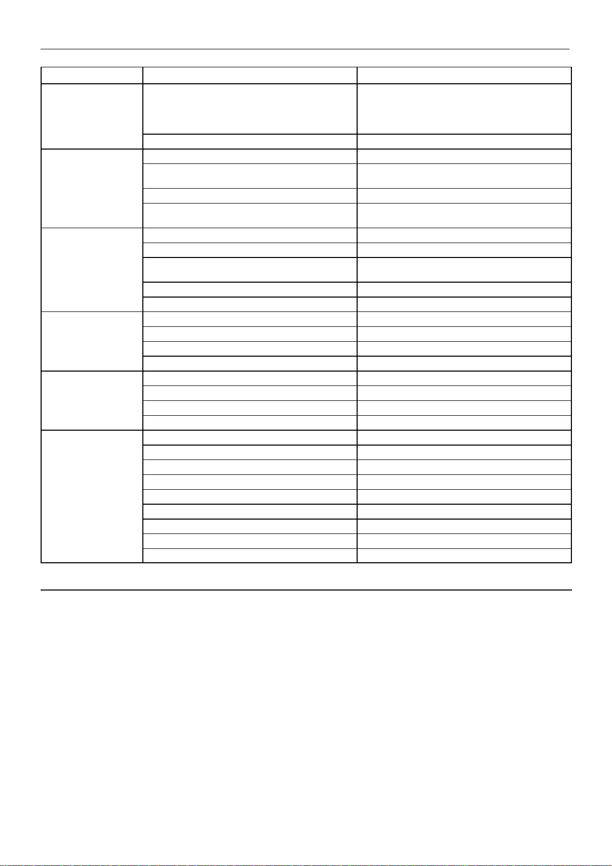
PROBLEM CAUSE REMEDY
Compressor fails to
start
Machine shutsdown High airend temperature. Top up coolant.
periodically
High current draw Compressor operating above rated pressure. Set pressure to correct rating for machine.
Low current draw Air filter contaminated. Change air filter.
High discharge Defective or incorrect pressure switch setting. Replace or set pressure to correct rating for machine.
pressure
Low system air Separator cartridge contaminated. Fit new Separator cartridge.
pressure
Mains power or Control voltage not available. § Check incoming power supply .
§ Check the control circuit fuse.
§ Check the transformer secondary windings for the
control voltage.
Defective Star / Delta timer. § Change Star / Delta timer.
Motor overload. § Set overload to correct value and switch to manual
reset.
Belt stretch protection (when fitted). Change belt.
Line voltage variation. § Ensure voltage does not drop below 10% on start up
and 6% running.
Separator cartridge contaminated. Change air filter, and separator cartridge.
Low voltage. § Ensure voltage does not drop below 10% on start up
and 6% running.
Unbalanced voltage. Correct incoming supply voltage.
Damaged airend. † Change Airend.
Compressor operating unloaded. Set pressure to correct rating for machine.
High voltage. Reduce site voltage to correct operating voltage.
Defective inlet valve. † Fit inlet valve service kit.
Load solenoid valve defective. † Fit load solenoid service kit.
Blowdown valve defective. † Fit blowdown solenoid service kit.
Inlet valve malfunction. † Fit inlet valve service kit.
Incorrect pressure switch setting. Set pressure to correct rating for machine.
Minimum pressure valve malfunction. † Fit Minimum pressure valve service kit.
Load solenoid valve defective. † Fit load solenoid service kit.
Blowdown valve defective. † Fit blowdown solenoid service kit.
Drive belt slipping. Fit new belt and tensioner.
Air system leaks. † Fix leaks.
Inlet valve malfunction. † Fit inlet valve service kit.
System demand exceeds compressor delivery. Reduce demand or install additional compressor.
NOTES:
§ Must be carried out by a competent electrician.
† This work is recommended to be carried out only by an Ingersoll–Rand authorized service technician.
SSR UP6 15, UP6 20, UP6 25, UP6 30
Page 30
30
TROUBLE SHOOTING
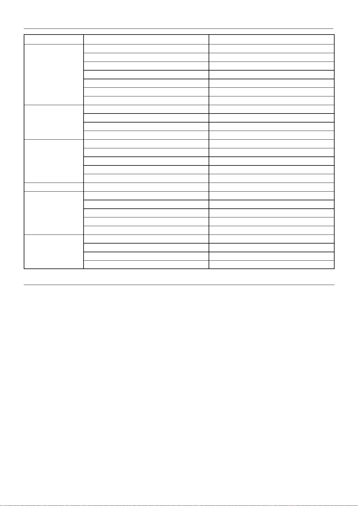
PROBLEM CAUSE REMEDY
Compressor trips due to Compressor operating above rated pressure. Set pressure to correct rating for machine.
over temperature
Excessive coolant Separator cartridge leak. Fit new Separator cartridge.
consumption
Excessive noise level Air system leaks. † Fix leaks.
Shaft seal leaking Defective shaft seal. † Fit Airend shaft seal kit.
Pressure relief valve Defective switch or incorrect pressure switch setting. Replace or set pressure to correct rating for machine.
opens
Black residue on belt Drive belt slipping. Replace belt and tensioner.
guard/cooler box
Package pre–filter blocked. Clean / replace package pre–filter.
Cooler blocked. Clean cooler.
Missing or incorrectly fitted enclosure panels Ensure that all enclosure panels are correctly fitted
Low coolant level. Top up coolant and check for leaks.
High ambient temperature. Re–site compressor.
Restricted cooling air flow. Ensure correct air flow to compressor.
Blocked separator cartridge drain. † Remove fittings and clean.
Compressor operating below rated pressure. Set pressure to correct rating for machine.
Coolant system leak. † Fix leaks.
Airend defective. † Change Airend.
Belts Slipping. Replace belt and tensioner.
Motor defective. † Replace motor.
Loose components. † Retighten loose items.
Minimum pressure valve malfunction. † Fit Minimum pressure valve service kit.
Load solenoid valve defective. † Fit load solenoid service kit.
Blowdown valve defective. † Fit blowdown solenoid service kit.
Inlet valve malfunction. † Fit inlet valve service kit.
Pulleys misaligned. Re–align pulleys.
Worn pulleys. † Replace pulleys and belt.
Gas strut failed. Replace belt and tensioner.
NOTES:
§ Must be carried out by a competent electrician.
† This work is recommended to be carried out only by an Ingersoll–Rand authorized service technician.
SSR UP6 15, UP6 20, UP6 25, UP6 30
 Loading...