

Page 1
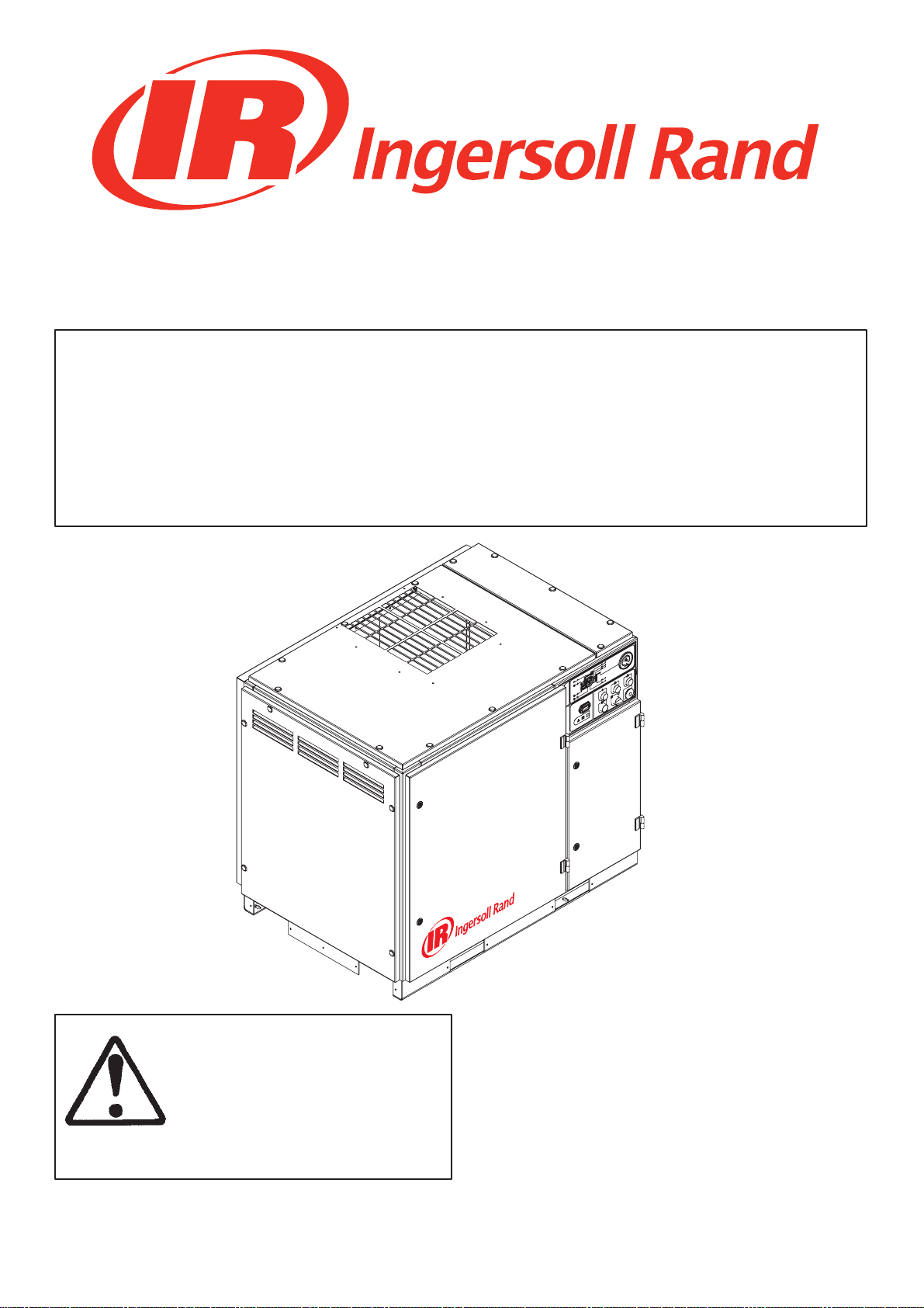
UP6 15, UP6 20, UP6 25, UP6 30
OPTIONS MANUAL
Intellisys Option
Dryer Option
High Dust Option
Outdoor Module Option
PORO Option
60Hz
This manual contains
important safety information
and must be made available
to personnel who operate and
maintain this machine.
C.C.N. : 80445174
REV : B
DATE : JANUARY 2009
Page 2

Page 3

CONTENTS & ABBREVIATIONS
http:/air.ingersollrand.com
UP6 15, UP6 20, UP6 25, UP6 30
1
CONTENTS
1 CONTENTS
2 FOREWORD
3 DECALS
6 SAFETY
8 INTELLISYS OPTION
31 DRYER OPTION
47 HIGH DUST FILTER OPTION
48 OUT DOOR MODULE OPTION
49 PORO OPTION – ELECTRO–PNEUMATIC
53 PORO OPTION – INTELLISYS
ABBREVIATIONS & SYMBOLS
#### Contact Ingersoll Rand for serial number
–>#### Up to Serial No.
####–> From Serial No.
* Not illustrated
{ Option
NR Not required
AR As required
SM Sitemaster/Sitepack
HA High ambient machine
WC Watercooled machine
AC Aircooled machine
ERS Energy recovery system
T.E.F.C. Totally enclosed fan cooled motor (IP55)
O.D.P. Open drip proof (motor)
Page 4
2
UP6 15, UP6 20, UP6 25, UP6 30
http:/air.ingersollrand.com
FOREWORD
This manual is provided to cover instructions and technical data
for additional options to the standard UP compressor range. It is
provided as a SUPPLEMENT to the standard operators and parts
manuals and should NOT be used for the operation of the
complete machine.
The contents of this manual are considered to be proprietary and
confidential to Ingersoll Rand and should not be reproduced without
the prior written permission of Ingersoll Rand.
Nothing contained in this document is intended to extend any
promise, warranty or representation, expressed or implied, regarding
the Ingersoll Rand products described herein. Any such warranties or
other terms and conditions of sale of products shall be in accordance
with the standard terms and conditions of sale for such products, which
are available upon request.
This manual contains instructions and technical data to cover
routine operation and scheduled maintenance tasks by operation and
maintenance staff. Major overhauls are outside the scope of this
manual and should be referred to an authorized Ingersoll Rand service
department.
All components, accessories, pipes and connectors added to the
compressed air system should be:
. of good quality, procured from a reputable manufacturer and,
wherever possible, be of a type approved by Ingersoll Rand.
. clearly rated for a pressure at least equal to the machine maximum
allowable working pressure.
. compatible with the compressor lubricant/coolant.
. accompanied with instructions for safe installation, operation and
maintenance.
Details of approved equipment are available from Ingersoll Rand
Service departments.
The use of non–genuine spare repair parts other than those
included within the Ingersoll Rand approved parts list may create
hazardous conditions over which Ingersoll Rand has no control.
Therefore Ingersoll Rand does not accept any liability for losses
caused by equipment in which non–approved repair parts are installed.
Standard warranty conditions may be affected.
The intended uses of this machine are outlined below and examples
of unapproved usage are also given, however Ingersoll Rand cannot
anticipate every application or work situation that may arise.
IF IN DOUBT CONSULT SUPERVISION.
This machine has been designed and supplied for use only in the
following specified conditions and applications:
. Compression of normal ambient air containing no known or
detectable additional gases, vapors, or particles
. Operation within the ambient temperature range specified in the
GENERAL INFORMATION section of this manual.
The use of the machine in any of the situation types listed in
table 1:–
a) Is not approved by Ingersoll Rand,
b) May impair the safety of users and other persons, and
c) May prejudice any claims made against Ingersoll Rand.
TABLE 1
Use of the machine to produce compressed air for:
a) direct human consumption
b) indirect human consumption, without suitable filtration and purity
checks.
Use of the machine outside the ambient temperature range
specified in the GENERAL INFORMATION SECTION of this manual.
Use of the machine where there is any actual or foreseeable risk of
hazardous levels of flammable gases or vapors.
THIS MACHINE IS NOT INTENDED AND MUST NOT BE
USED IN POTENTIALLY EXPLOSIVE ATMOSPHERES,
INCLUDING SITUATIONS WHERE FLAMMABLE GASES OR
VAPOURS MAY BE PRESENT.
Use of the machine fitted with non Ingersoll Rand approved
components.
Use of the machine with safety or control components missing or
disabled.
The company accepts no responsibility for errors in translation of
this manual from the original English version.
Ingersoll Rand reserves the right to make changes and
improvements to products without notice and without incurring any
obligation to make such changes or add such improvements to
products sold previously.
INTELLISYS is a registered trademark of Ingersoll Rand
Company USA.
¤ COPYRIGHT 2008
INGERSOLL RAND
Page 5

DECALS 3
http:/air.ingersollrand.com
UP6 15, UP6 20, UP6 25, UP6 30
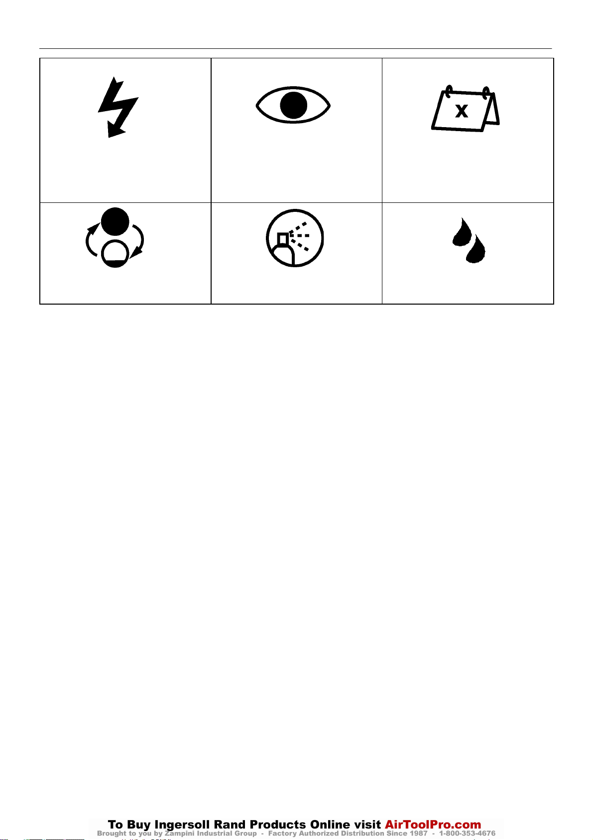
ISO SYMBOLS
GRAPHIC FORM AND MEANING OF ISO SYMBOLS
Prohibition / Mandatory Information / Instructions Warning
Use fork lift truck from this side only. RESET Do not use fork lift truck from this side.
Emergency stop. On (power). Off (power).
AUTOMATIC RESTART MAINTENANCE MAINTENANCE PROHIBITED
FRAGILE KEEP DRY THIS WAY UP
USE NO HOOKS NO SIDE CLAMPS HOURS
Page 6
DECALS4
UP6 15, UP6 20, UP6 25, UP6 30
http:/air.ingersollrand.com
POWER INSPECT
CHANGE / REPLACE CLEAN
Every X months, if sooner than required by
operating hours
MOISTURE
Page 7
DECALS 5
http:/air.ingersollrand.com
UP6 15, UP6 20, UP6 25, UP6 30
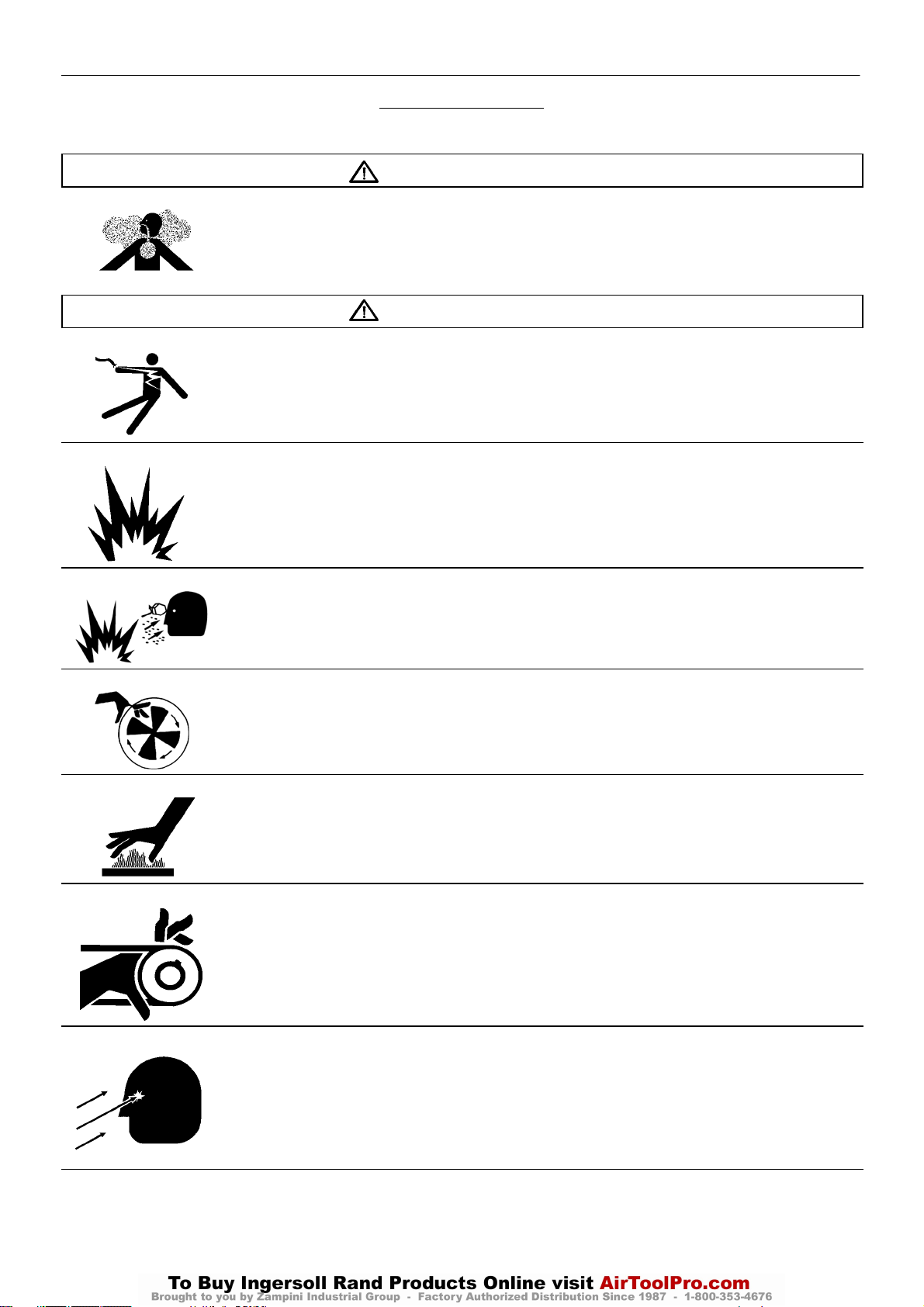
ANSI SYMBOLS
GRAPHIC FORM AND MEANING OF ANSI SYMBOLS
DANGER
INTAKE AIR. Can contain carbon monoxide or other contaminants. Will cause serious injury or death. Ingersoll Rand
air compressors are not designed, intended or approved for breathing air. Compressed air should not be used for
breathing air applications unless treated in accordance with all applicable codes and regulations.
WARNING
HAZARDOUS VOLTAGE. Can cause serious injury or death. Disconnect power and bleed pressure from tank before
servicing. Lockout/Tagout machine. Compressor must be connected to properly grounded circuit. See Grounding
Instructions in manual. Do not operate compressor in wet conditions. Store indoors.
RISK OF FIRE OR EXPLOSION. Electrical arcing from compressor components can ignite flammable liquids and
vapors which can result in serious injury. Never operate the compressor near flammable liquids or vapors. If used to
spray flammable materials, keep compressor at least 20ft away from the spray area.
HIGH PRESSURE AIR. Rusted tanks can cause explosion and severe injury or death. Receiver under pressure.
Operator should relieve tank pressure before performing maintenance. In addition to automatic drain, operate manual
drain valve weekly. Manual drain valve located at bottom of the tank.
MOVING PARTS. Can cause serious injury. Do not operate with guards removed. Machine may start automatically.
Disconnect power before servicing. Lockout/Tagout machine.
HOT SURFACES. Can cause serious injury. Do not touch. Allow to cool before servicing. Do not touch hot
compressor or tubing.
EXPOSED MOVING BELTS AND SHEAVES.
Can cause severe injury or death.
Do not operate without guard in place. Disconnect power before servicing.
Lockout/Tagout machine.
Air flow exhaust may contain flying debris.
Safety protection should be worn at all times.
Page 8

6
UP6 15, UP6 20, UP6 25, UP6 30
http:/air.ingersollrand.com
SAFETY
DANGER!
Hazard that WILL cause DEATH, SEVERE INJURY or substantial
property damage if ignored. Instructions must be followed precisely to
avoid injury or death.
WARNING!
Hazard that CAN cause DEATH, SEVERE INJURY or substantial
property damage if ignored. Instructions which must be followed
precisely to avoid injury or death.
CAUTIONS!
Cautions call attention to instructions which must be followed
precisely to avoid damaging the product, process or its surroundings.
NOTES
Notes are used for supplementary information.
BREATHING AIR PRECAUTION
Ingersoll Rand air compressors are not designed, intended or
approved for breathing air. Compressed air should not be used for
breathing air applications unless treated in accordance with all
applicable codes and regulations.
General Information
Ensure that the operator reads and understands the decals and
consults the manuals before maintenance or operation.
Ensure that the Operation and Maintenance manual is not removed
permanently from the machine.
Ensure that maintenance personnel are adequately trained,
competent and have read the Maintenance Manuals.
Do not point air nozzles or sprayers toward anyone.
Compressed air and electricity can be dangerous. Before
undertaking any work on the compressor, ensure that the electrical
supply has been isolated and the compressor has been relieved of all
pressure.
Wear eye protection when operating or servicing compressor.
All persons positioned near to operating machinery should be
equipped with hearing protection and given instructions on its use in
accordance with workplace safety legislation.
Make sure that all protective covers are in place and that the
canopy/doors are closed during operation.
The specification of this machine is such that the machine is not
suitable for use in flammable gas risk areas.
Installation of this compressor must be in accordance with
recognized electrical codes and any local Health and Safety Codes.
The use of plastic bowls on line filters can be hazardous. Their
safety can be affected by either synthetic lubricants, or the additives
used in mineral oils. Ingersoll Rand recommends that only filters with
metal bowls should be used on a pressurized system.
Compressed air
Compressed air can be dangerous if incorrectly handled. Before
doing any work on the unit, ensure that all pressure is vented from the
system and that the machine cannot be started accidentally.
All air pressure equipment installed in or connected to the machine
must have safe working pressure ratings of at least the machine rated
pressure.
If more than one compressor is connected to one common
downstream plant, effective isolation valves must be fitted and
controlled by work procedures, so that one machine cannot accidently
be pressurized / over pressurized by another.
Compressed air must not be used for a direct feed to any form of
breathing apparatus or mask.
The discharged air contains a very small percentage of compressor
lubricant and care should be taken to ensure that downstream
equipment is compatible.
If the discharged air is to be ultimately released into a confined
space, adequate ventilation must be provided.
When using compressed air always use appropriate personal
protective equipment.
All pressure containing parts, especially flexible hoses and their
couplings, must be regularly inspected, be free from defects and be
replaced according to the Manual instructions.
Compressed air can be dangerous if incorrectly handled. Before
doing any work on the unit, ensure that all pressure is vented from the
system and that the machine cannot be started accidentally.
Avoid bodily contact with compressed air.
All safety valves located in the separator tank must be checked
periodically for correct operation.
Do not over–pressurize the receiver tank or similar vessels beyond
design limits.
Do not use a receiver tank or similar vessels that fail to meet the
design requirements of the compressor. Contact your distributor for
assistance.
Do not drill into, weld or otherwise alter the receiver tank or similar
vessels.
Materials
The following substances are used in the manufacture of this
machine and may be hazardous to health if used incorrectly:
. preservative grease
. rust preventative
. compressor coolant
AVOID INGESTION, SKIN CONTACT AND INHALATION OF
FUMES
Transport
When loading or transporting machines ensure that the specified
lifting and tie down points are used.
Lifting equipment must be properly rated for the weight of the
compressor.
Do not work on or walk under the compressor while it is suspended.
WARNING
Imposing a normal or emergency stop on the compressor will
only relieve presure upstream of the minimum pressure valve on
top of the separator tank.
If maintenance work is required downstream of this valve, ensure
that all pressure is relieved at the process vent point external to
the compressor
Ensure that the machine is operating at the rated pressure and that
the rated pressure is known to all relevant personnel.
Page 9

Electrical
http:/air.ingersollrand.com
UP6 15, UP6 20, UP6 25, UP6 30
Keep all parts of the body and any hand–held tools or other
conductive objects, away from exposed live parts of the compressor
electrical system. Maintain dry footing, stand on insulating surfaces
and do not contact any other portion of the compressor when making
adjustments or repairs to exposed live parts of the compressor
electrical system.
WARNING
Any electrical connections or adjustments should only be
made by a suitably qualified electrician
Close and lock all access doors when the compressor is left
unattended.
Do not use extinguishers intended for Class A or Class B fires on
electrical fires. Use only extinguishers suitable for class BC or class
ABC fires.
Attempt repairs only in clean, dry, well lighted and ventilated areas.
Connect the compressor only to electrical systems that are
compatible with its electrical characteristics and that are within it’s rated
capacity.
Condensate disposal
As waste water regulations vary by country and region it is the
responsibility of the user to establish the limitations and regulations in
their particular area. Ingersoll Rand and its associated distributors are
happy to advise and assist in these matters.
For further information, consult Material Data
80440043 MSDS, Ultra Coolant English
80440068 MSDS, Ultra Coolant Spanish
80440050 MSDS, Ultra Coolant Portuguese
80442254 MSDS, Xtend Food Grade Coolant English
SAFETY
7
Page 10
8
UP6 15, UP6 20, UP6 25, UP6 30
http:/air.ingersollrand.com
INTELLISYS CONTROL AND INSTRUMENTATION
INTELLISYS OPTION
PRIOR TO STARTING
1. Check coolant level. Add if necessary.
2. Make sure main discharge valve is open.
3. Turn on electrical isolator. The power L.E.D. will illuminate and the
display will indicate ‘Ready to start’.
WARNING
Make sure that all protective covers are in place.
STARTING
Press ‘Start’ [24]. The compressor will start and then load
automatically.
POWER OUT RESTART (Optional)
If this setting is set to ON, the compressor will automatically restart
when power is returned to the compressor if it was operating when
power was removed.
POWER OUT RESTART TIME
If the power out restart setting is set to ON, this is the number of
seconds from the time power is restored until the compressor starts.
The power out restart horn will sound during this time.
NORMAL STOPPING
1. Press ‘Unloaded Stop’[25]. The compressor will unload then stop.
2. Turn off electrical isolator.
Page 11

INTELLISYS OPTION
http:/air.ingersollrand.com
UP6 15, UP6 20, UP6 25, UP6 30
9
EMERGENCY STOP
1. Press ‘Emergency stop button’ [26] and the compressor will stop
immediately.
2. Turn off electrical isolator.
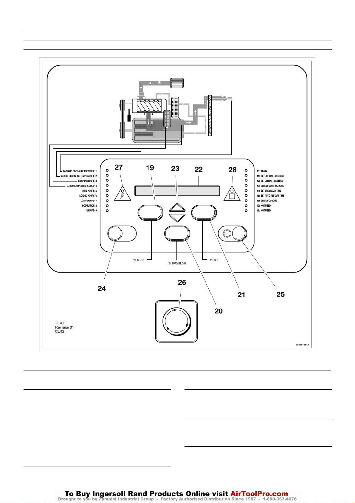
INSTRUMENT PANEL FUNCTION
1 PACKAGE DISCHARGE PRESSURE L.E.D.
This will illuminate when the display indicates the package
discharge pressure.
2 AIREND DISCHARGE TEMPERATURE L.E.D.
This will illuminate when the display indicates the airend discharge
temperature.
3 SUMP PRESSURE L.E.D.
This will illuminate when the display indicates the sump pressure.
4 SEPARATOR PRESSURE DROP L.E.D.
This will illuminate when the display indicates the separator
pressure drop.
5 TOTAL HOURS L.E.D.
This will illuminate when the display indicates the total compressor
running hours.
6 LOADED HOURS L.E.D.
This will illuminate when the display indicates the total loaded
compressor hours.
7 LOAD/UNLOAD L.E.D.
This will illuminate when the compressor is running onload.
15 L.E.D.–Set auto restart time.
16 L.E.D.–Select options.
17 L.E.D.–Not used.
18 L.E.D.–Not used.
19 DISPLAY SELECT BUTTON
Press to index through compressor operating conditions. The
corresponding L.E.D. will illuminate adjacent to display.
This is used to select alternative status displays (after
approximately 5 minutes, the display defaults to the package discharge
pressure). Depressing this button in the set point routine will cause exit
to checking machine for 2 seconds, then ready to start.
20 LOAD/UNLOAD BUTTON
These are used to manually switch the compressor between a
loaded control mode (e.g. on/off line) and unloaded running.
See L.E.D.
21 SET BUTTON
Depressing this button when the compressor is stopped will enable
entry into the set point routine. When in the set point routine, depressing
this button will cause the controller to move on to the next set point
setting, saving the new value if one has been entered.
A warning reset is obtained by depressing this button (while the
machine is running). An alarm reset is obtained by depressing this
button twice within 3 seconds (the alarm condition will remain if the
indicated fault has not been rectified).
22 LIQUID CRYSTAL DISPLAY
This indicates the status of the compressor, set up parameters and
warning/alarm messages. When the compressor is running, the
display will normally show the package discharge pressure.
8 MODULATION L.E.D.
This will illuminate when the compressor is running in modulation
mode. (Note: capacity modulation will occur only if the appropriate
regulation pneumatics are fitted to the compressor).
9 UNLOAD L.E.D.
This will illuminate when the compressor is running in unload mode.
10 ALARM L.E.D.
This will flash when a warning condition exists. The warning
detected will be displayed and the compressor will continue to run. The
warning can be reset by depressing set [21].
It will illuminate when an alarm condition has occurred. The
compressor will shutdown immediately. The alarm can be reset by
depressing set [21] twice within 3 seconds.
OTHER L.E.D.s
These will illuminate during the set point routine to indicate which
function is being adjusted.
11 L.E.D.–Set off line pressure.
12 L.E.D.–Set on line pressure.
13 L.E.D.–Select control mode.
14 L.E.D.–Set star delta time.
23 ARROW KEYS
These are used to index through warning and alarm messages. In
the set point routine, these buttons are used to increase/decrease set
point values and enable/disable some operation conditions.
The arrow keys are also used to select pressure bands 1 (Y) or 2
(B) during normal operation of the compressor.
24 START BUTTON
This button when depressed will cause the compressor to start and
load automatically, provided that the controller detects a demand for air.
When pressed in the display mode, it will cause exit to checking
machine for 2 seconds, then ready to start.
25 UNLOADED STOP
This button when depressed while the compressor is running, will
unload the compressor (if not already unloaded) for 10 seconds and
then stop. This is the normal method for stopping the compressor. If the
compressor is already stopped, it will execute an L.E.D. check (all the
L.E.D.s should illuminate) and display the controller software revision.
26 EMERGENCY STOP
This button when depressed will stop the compressor immediately
and display an emergency stop alarm message.
Page 12

10
UP6 15, UP6 20, UP6 25, UP6 30
http:/air.ingersollrand.com
INTELLISYS OPTION
27 POWER L.E.D.
This will illuminate when the 8V controller supply is available.
28 AUTOMATIC RESTART L.E.D.
This will illuminate when the machine has shutdown due to low air
demand. The compressor will restart and load automatically as soon
as the demand for air resumes.
DISPLAY MESSAGES
When the compressor is running normally, the display will indicate
the package discharge pressure and illuminate the corresponding
L.E.D. [1]. An arrow will also appear in the far right of the display
indicating pressure band selection. Pressing display select [19] will
change the display value and the corresponding L.E.D. will illuminate.
The controller monitors all aspects of the compressor while running and
will display warnings or in severe conditions execute an emergency
stop and display alarm conditions.
MACHINE CONTROL MODES
CAPACITY CONTROL
The compressor is designed to work with two types of capacity
control, to suit the individual plant requirements. These controls are:–
A. On line – Off line. (Fitted as standard)
B. On line – Off line, with Upper Range Modulation. (Optional extra)
Either is available by selection at the control panel.
ON LINE – OFF LINE CONTROL
For applications that require a widely varying air demand, this
mode of control will deliver air at full capacity or zero capacity with
low receiver pressure.
This mode of operation is controlled by the pressure transducer
responding to changes in plant air pressure. This sensorenergizes
the load solenoid valve which in turn operates the venting valve
(blowdown) and the closing of the atmospheric vent opening in the
air inlet valve.
The compressor then delivers full capacity air to the plant
system. If the air pressure in this system rises to the upper set point
of the pressure setting, the load solenoid valve is de–energized
allowing the inlet valve to close. At the same time, the venting valve
opens allowing the receiver pressure to drop.
The pressure setting has a range of 12 psi (0.83 bar) between
its upper and lower set points.The upper set point is set at 3 psi (0.2
bar) above the compressor rated discharge pressure.
UPPER RANGE MODULATION CONTROL (Optional Extra)
For plants having a relatively high and constant air demand,
Upper Range Modulation is the recommended mode of control.
Upper range modulation retains the features of On line – Off line
control but provides the throttling of the inlet air flow as the line
pressure rises to the upper set point of the off–line pressure setting.
AUTOMATIC START/STOP
For plants that have a widely varying plant air demand, larger air
storage capacity, and/or want automatically available stand–by air
capacity, Automatic Start–Stop Control Option is available.
During periods of low demand, if the line pressure rises to the off line
air pressure set point of the lntellisys® , a timer is energized and begins
to time out. The automatic restart time is adjustable in a 2–60 minute
range. The timer will continue to operate as long as the plant line
pressure remains above the on line set point of the Intellisys® . If the
timer continues to operate for as long as its adjusted time setting, a
contact in the lntellisys opens to de–energize the compressor starter
coils. At the same time, a yellow Automatic Restart light on the
lntellisys® panel is lit and the message AUTO RESTART will be
displayed to indicate the compressor has shut down automatically and
will restart automatically.
The automatic restart will take place when the line pressure drops
to the online set point of the Intellisys® .
To operate in the automatic start/stop mode, proceed with the
following steps:
1. Press the SET button until the message AUTO S/S OFF is
displayed.
2. Push the up or down arrows to select the auto start/stop function (on
or off). AUTO S/S OFF in the display indicates auto start/stop is
disabled (off). AUTO S/S ON in the display indicates auto start/stop is
enabled (on). Press the SET button to store function. The display will
flash to acknowledge and then display AUTO S/S 10 MIN.
3. Press the up or down arrows to select the desired automatic restart
time (2–60 min. range). The default value is 10 minutes. Press SET
button to store the value.The display will flash to acknowledge. Press
the DISPLAY SELECT button or wait 30 seconds for the controller to
automatically exit the set routine.The display returns to READY TO
START.
4. Start the compressor and adjust the isolation valve to allow the unit
to slowly reach the offline pressure and unload.The compressor should
run for a minimum of 10 min. and unloaded for the pre–set time and then
shut down.
5. The compressor should restart automatically when the system air
pressure drops below the online air pressure setting.
CONTROLLER WARNING MESSAGES
In the event of a warning, the controller will display a message and
thealarm L.E.D. [10] will flash. The warning message will alternate with
the normal display every 4 seconds, the compressor will continue to run
but the fault should be rectified as soon as possible. The arrow keys
[23] should be used to index the display for any additional warning
messages. A warning message may be reset by depressing set [21]
once.
NOTE:
The warning will recur if the fault has not been rectified. The
following warning messages may be displayed:
SEPARATOR ELEMENT
The separator element is dirty or blocked and should be replaced.
By bleeding off a small amount from the regulator valve, which
energises the Modulate Solenoid Valve, a reduction in the air signal
to the pneumatic cylinder on the inlet valve allows the cylinder to
‘trim’ the inlet valve position as dictated by changing line pressure.
Modulation begins when the compressor reaches about 94% of the
rated line pressure and is factory set to modulate down to
approximately70% of rated capacity.
If the air demand decreases to a level below the 70% modulated
output, the line pressure will increase slightly to the upper limit of the
pressure setting, when the compressor then changes to the Off line
control position and operates with the receiver vented.
AIREND TEMPERATURE
The airend temperature reaches 97% of the high airend
temperatureset point (i.e. 223 F (106 C)).
Page 13

INTELLISYS OPTION
http:/air.ingersollrand.com
UP6 15, UP6 20, UP6 25, UP6 30
11
CONTROLLER ALARMS
In the event of an alarm, the controller will execute an emergency
stop, the alarm L.E.D. [10] will illuminate and an alarm message will be
displayed. The arrow keys [23] should be used to index the display for
any additional alarm messages. An alarm is reset by depressing set
[21] twice within a 3 second period after the fault has been rectified. The
compressor will restart only when all alarm conditions have been
rectified. The following alarm messages may be displayed (For fault
correction see the Fault Finding section):
STARTER FAULT
The contactor sequence during start or stop is incorrect.
AIREND TEMPERATURE
The airend discharge temperature is above the high temperature
set point.
MOTOR OVERLOAD
The motor overload contacts are open. The motor overload must be
reset before the controller can be reset.
REVERSE ROTATION
No sump pressure is detected after the first 2 seconds of running.
Isolate the machine and reverse the mains supply connections before
resuming.
OVER PRESSURE
The line pressure is 15 psi (1 bar) greater than the rated discharge
pressure.
TEMPERATURE SENSOR 1
The airend temperature sensor/ connecting cable has failed.
TEMPERATURE SENSOR 2
The separator tank temperature sensor/connecting cable has
failed.
PRESSURE SENSOR
Indicates pressure transducer failure / connecting cable fault.
FIELD OPTION/S
Before installation and operation of this option, these instructions
should be studied carefully to obtain a clear knowledge of the option
and its application to the compressor.
REMOTE START/STOP
The Remote Start/Stop Option allows the operator to control the
compressor from a remote mounted start/stop station.Terminal points
are provided in connector J1 in the top of the lntellisys controller; one
a connection for a normally closed stop switch (terminals 3 and 4), and
one for a normally open, momentary contact start switch (terminals 5
and 6). Refer to the compressor wiring schematic for specific
connection points.
For safety, a selection is available in the lntellisys set–points to
disable the remote start and stop function.This allows the compressor
to be fully controlled by the lntellisys and not from the remote
start/stop station.
If the remote start switch is momentarily closed, the lntellisys
starts the compressor.The remote stop switch is normally closed. If the
remote stop switch opens, the compressor will unload and stop.The
compressor cannot restart until the remote stop switch has been reset
to a closed position. (EMERGENCY STOP will display on the
lntellisys if the stop switch is not closed).
To operate in the remote start/stop mode, proceed with the
following steps:
1. Press the SET button until the message REMOTE S/S OFF is
displayed.
2. Push the up or down arrows to select the remote start/stop function
(on or off). REMOTE S/S OFF in the display indicates remote start/stop
is disabled (off). REMOTE S/S ON in the display indicates remote
start/stop in enabled (on). Press the SET button to store the function.
The display will flash to acknowledge. Press the DISPLAY SELECT
button or wait 30 seconds for the controller to automatically exit the set
routine.The display returns to READY TO START.
3. Start the compressor with the Start button on the Intellisys control
panel.The compressor must be started locally first before the Remote
Start/Stop buttons are activated by the lntellisys.
FAILED CALIBRATION
During calibration routine, a 10% of scale error has been detected.
Ensure that the separator is completely blowndown and repeat
calibration.
CONTROL POWER LOSS
The 48Vac signal is not present at the controller.
REMOTE START FAILURE
Momentary remote start has not disengaged before star–delta
transition. This alarm is active only if the remote start/stop is enabled.
REMOTE STOP FAILURE
The momentary remote stop switch has not disengaged when the
start signal is received. This alarm is active only if the remote start/stop
is enabled.
EMERGENCY STOP
The emergency stop button is engaged.
LOW SUMP PRESSURE
The sump pressure drops below 15 psi (1 bar) during normal
operation.
Page 14
12
UP6 15, UP6 20, UP6 25, UP6 30
http:/air.ingersollrand.com
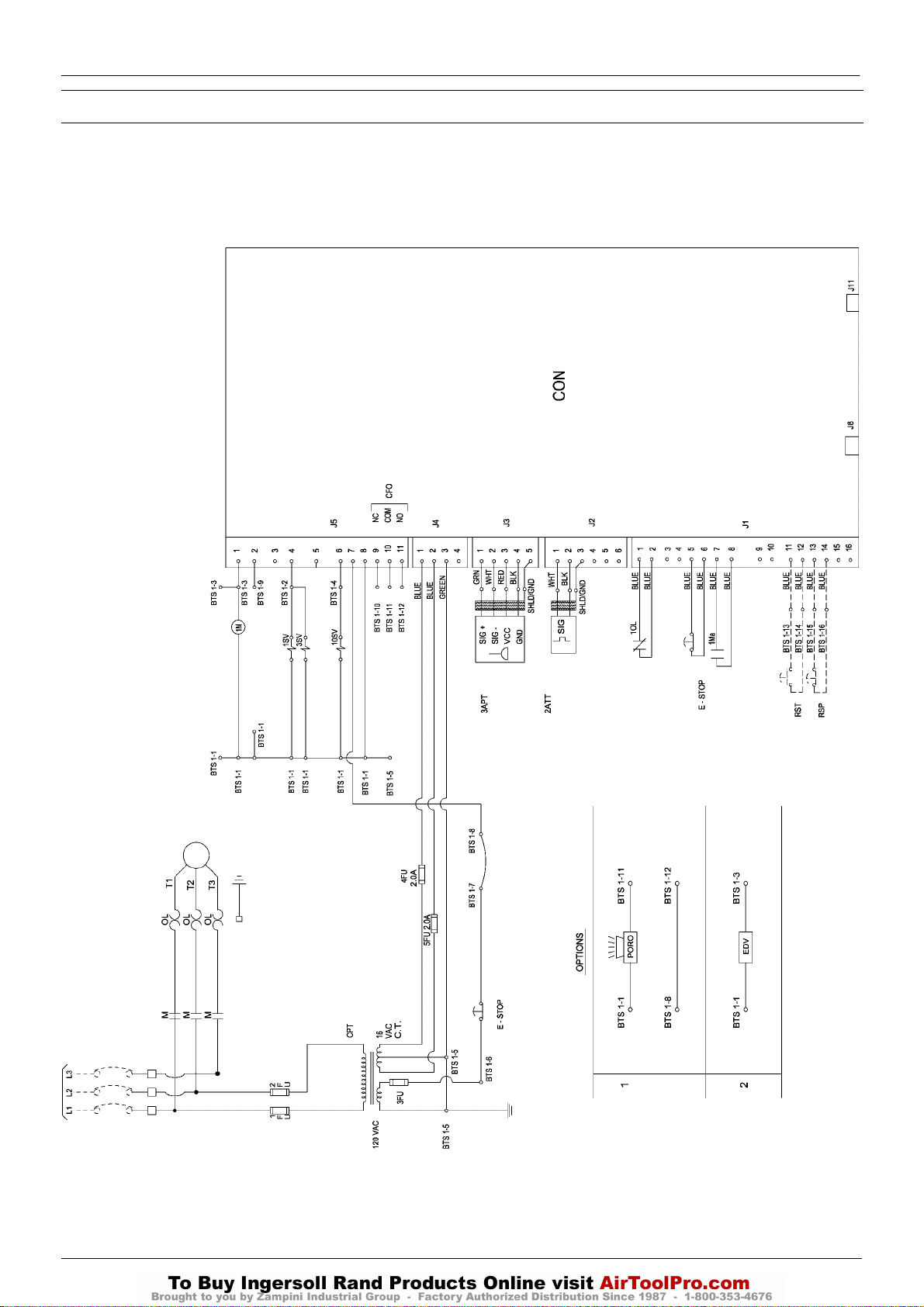
ELECTRICAL SCHEMATIC – DOL WITH INTELLISYS CONTROL
INTELLISYS OPTION
INTELLISYS – DOL
32343956
Revision D
Page 15

KEY
http:/air.ingersollrand.com
UP6 15, UP6 20, UP6 25, UP6 30
INTELLISYS OPTION
13
CON Controller, INTELLISYS
CPT Transformer, control
EDV Valve, electric drain
E–STOP Button, emergency stop
FU Fuse
M Contactor (main)
1M Coil, motor starter
OL Overload, motor starter
1SV Valve, solenoid (load) N.C
3SV Valve, solenoid (blowdown) N.O
10SV Valve, solenoid (line / sump) N.C
RST Remote start
(Optional)
RSP Remote stop
(Optional)
CFO Common fault output
PORO Power out restart (Optional)
2ATT Temperature sensor
3APT Pressure sensor
NOTES
1. Approved fused disconnect or circuit breaker per code
requirements must be provided by customer.
2. Dashed lines represent wiring by customer.
3. Sizing of electrical components not supplied by Ingersoll Rand is
the responsibility of the customer and should be done in
accordance with the information on the compressor data plate
and local electrical codes.
4. Unit will not restart automaticlly after power outage, except with
additional PORO option.
5. Circuit shown in normal position de–energized.
6. All wiring to be in accordance with local codes.
Page 16
14
UP6 15, UP6 20, UP6 25, UP6 30
http:/air.ingersollrand.com
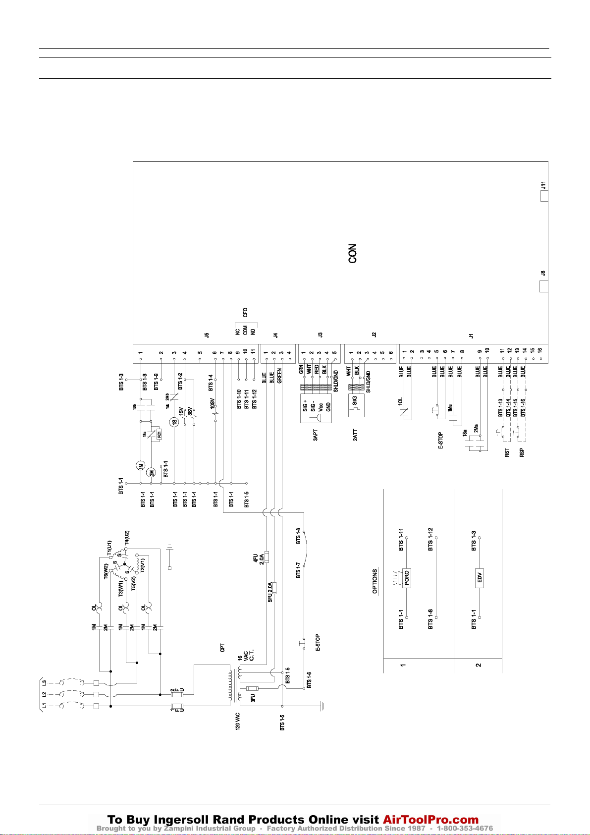
ELECTRICAL SCHEMATIC – STAR DELTA WITH INTELLISYS CONTROL
INTELLISYS OPTION
INTELLISYS – STAR DELTA
32343931
Revision E
Page 17

KEY
http:/air.ingersollrand.com
UP6 15, UP6 20, UP6 25, UP6 30
INTELLISYS OPTION
15
CON Controller, INTELLISYS
CPT Transformer, control
EDV Valve, electric drain
E–STOP Button, emergency stop
FU Fuse
1M Contactor (main)
2M Contactor (delta)
OL Overload, motor starter
1SV Valve, solenoid (load) N.C
3SV Valve, solenoid (blowdown) N.O
10SV Valve, solenoid (line / sump) N.C
RST Remote start
(Optional)
RSP Remote stop
(Optional)
CFO Common fault output
PORO Power out restart (Optional)
2ATT Temperature sensor
3APT Pressure sensor
1S Contactor (wye / star)
NOTES
1. Approved fused disconnect or circuit breaker per code
requirements must be provided by customer.
2. Dashed lines represent wiring by customer.
3. Sizing of electrical components not supplied by Ingersoll Rand is
the responsibility of the customer and should be done in
accordance with the information on the compressor data plate
and local electrical codes.
4. Unit will not restart automaticlly after power outage, except with
additional PORO option.
5. Circuit shown in normal position de–energized.
6. All wiring to be in accordance with local codes.
7. Blue – 16 Volts AC
Page 18
16
UP6 15, UP6 20, UP6 25, UP6 30
http:/air.ingersollrand.com
INTELLISYS OPTION
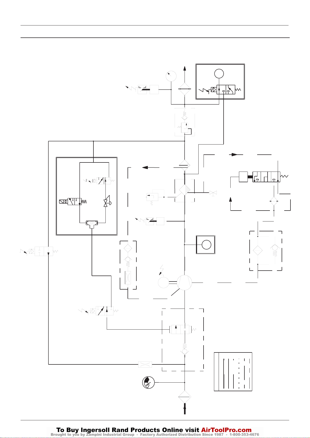
PIPING AND INSTRUMENTATION WITH INTELLISYS CONTROL
6SV
33
32
10SV
85584282
Revision D
INTELLISYS (OPTION)
REPLACES 10 AND 11
5SV
10
CONTINUED IN NEXT PAGE
11
P
39
9
8
7
T
6
40
42
41
17
18
12
T
14
15
3SV
20
19
MODULATION (OPTION)
3
1SV
16
5
21
4
M
34
INTELLISYS (OPTION)
REPLACES 12
B
A
2
PIPING LEGEND
13
F
E
C
D
22
1
Page 19
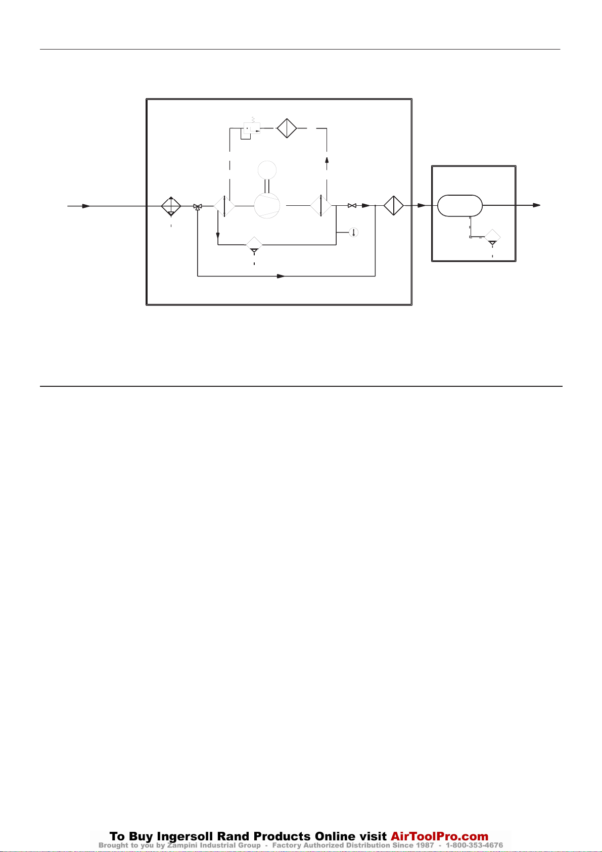
INTELLISYS OPTION
http:/air.ingersollrand.com
UP6 15, UP6 20, UP6 25, UP6 30
17
FROM PREVIOUS PAGE
KEY
1. Filter, air
2. Valve, inlet
3. Valve, solenoid (load)
4. Airend assembly
5. Motor
6. Tank, separator, Coarse
7. Separator, Fine
8. Valve, minimum pressure
9. Aftercooler
10.Gauge, pressure
11.Switch, discharge pressure
12.Switch, temperature
13.Filter, coolant
14.Thermostat
15.Cooler
16.Relay, overload Motor
17. Valve, safety
18 . Valve, Drain
19 . Screen, Scavenge
20 . Valve, Solenoid 3sv (Blowdown)
21 . Orifice
22 . Indicator, Air Filter Restriction
23 .Refrigerant Compressor
24.Evaporator
25 .Condenser
27
26
M
35
24
37 38
23
29
25
36
28
INTEGRAL DRYER (OPTION)
26.Filter, Refrigerant
27.Expansion Valve
28 .Indicator, Dew Point
29.Condensate Drain Valve
30.Receiver, Air
31.Auto Drain Valve
32.Valve, Solenoid 10sv (Line/Sump)
33.Transducer, Pressure
34.Sensor, Temperature
35.Moisture Separator
36.Filter, Air
37.3 Way Valve, Bypass
38.Valve, Isolation
39.Valve, Solenoid 5sv (Modulation)
40.Valve, Solenoid 6sv (Modulation)
41.Valve, Shuttle
42.Valve, Modulation
A Air/Coolant
B Air
C Coolant
D Condensate
E Component boundary
F Refrigerant
G Option
30
31
AIR RECEIVER (OPTION)
Page 20
18
UP6 15, UP6 20, UP6 25, UP6 30
http:/air.ingersollrand.com
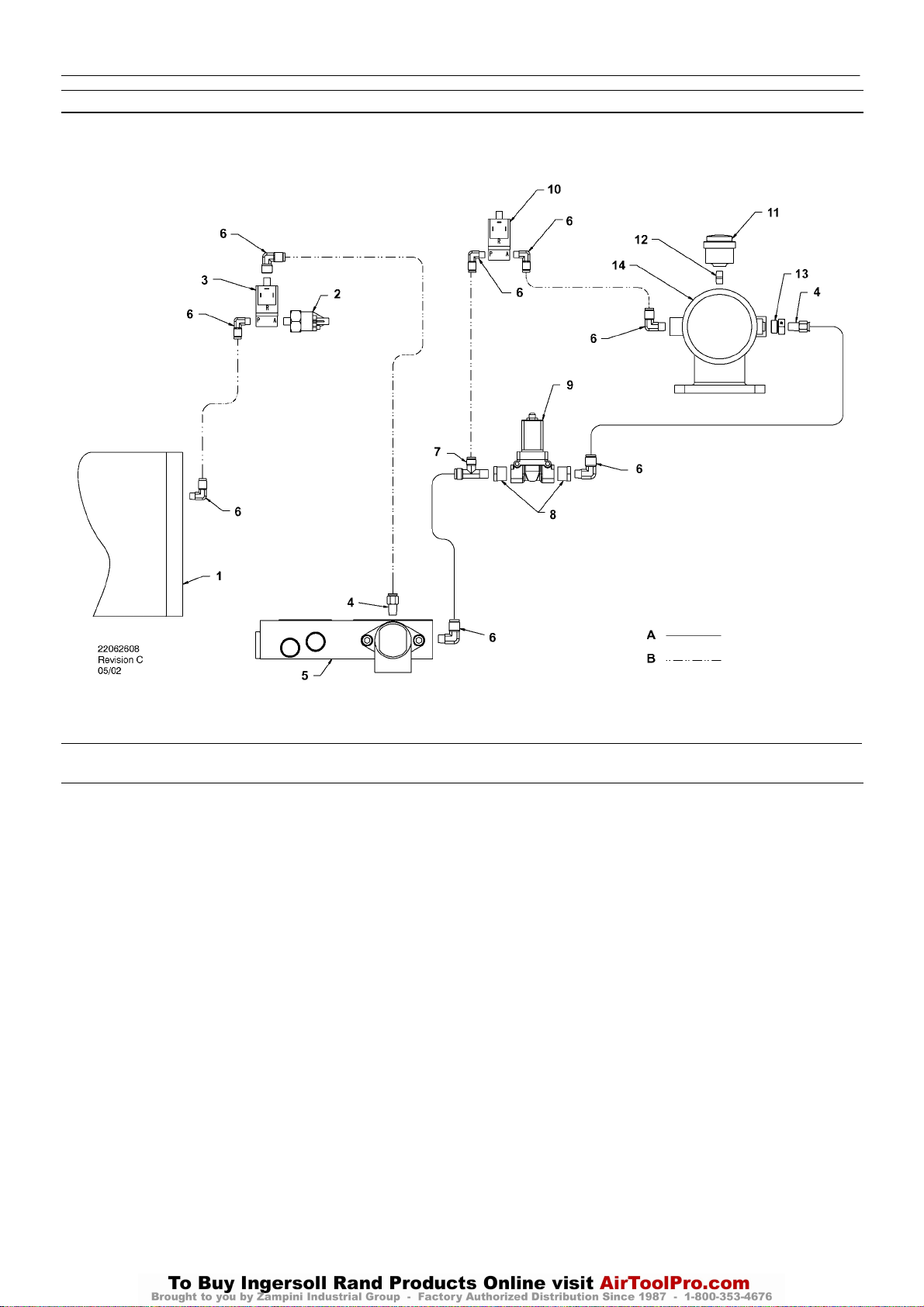
INTELLISYS CONTROL AND INSTRUMENTATION DIAGRAM
INTELLISYS OPTION
KEY
1. Tank, separator
2. Transducer, pressure
3. Valve, solenoid (Line / Sump)
4. Connector
5. Combination block
6. Elbow
7. Tee, male run
8. Reducer bushing
9. Valve, solenoid (Blowdown)
10.Valve, solenoid (Load)
11.Indicator air filter
12.Nipple
13.Adaptor
14.Intake valve assembly
NOTES:
A. Tubing 3/8 inch
B. Tubing 1/4 inch
Page 21
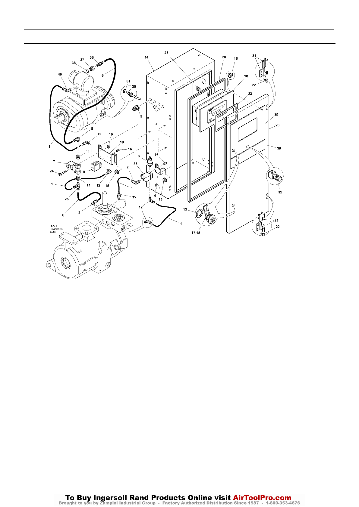
INTELLISYS PARTS – INSTRUMENTATION AND ELECTRICAL SYSTEM
http:/air.ingersollrand.com
UP6 15, UP6 20, UP6 25, UP6 30
INTELLISYS OPTION
19
Item ccn Qty. Description Item ccn Qty. Description
1 39124813 AR Tube (Nylon)
2 39155460 1 Elbow
3 39853809 1 Transducer
4 22107833 1 Bracket
5 92877018 5 Gland, cable
6 39124821 AR Tube (Nylon)
7 54654652 1 Valve, solenoid (Blowdown)
8 39155650 2 Elbow
9 54774302 1 Valve, solenoid (Load)
10 54755426 1 Bracket
11 95944625 2 Bushing
12 39155577 4 Elbow
13 93492072 2 Seal
14 22177174 1 Cabinet
15 96737564 14 Nut
16 96743182 8 Screw
17 85584340 4 Latch
*18 92829308 1 Key
19 96703756 2 Nut
20 22128763 1 Controller, INTELLISYS
21 22091193 2 Hinge
22 96743992 4 Screw
23 39495874 1 Gasket
24 96742754 2 Screw
25 22055909 1 Tee
26 22177190 1 Cabinet door
27 39133467 3 Mount
28 22177315 1 Gasket, door
29 22131155 1 Decal, controller
30 22137848 1 Sensor, temperature
31 39404157 1 ‘O’ Ring
32 22113344 1 Button, emergency stop
33 22289797 1 Valve, solenoid (line/sump)
*34 39192000 4 Grommet
35 39156393 1 Connector
36 39156419 1 Connector
37 54774997 1 Bush
38 39404165 1 ‘O’ Ring
39 22131148 1 Decal
40 39155478 1 Elbow
* Not illustrated
Page 22
20
UP6 15, UP6 20, UP6 25, UP6 30
http:/air.ingersollrand.com
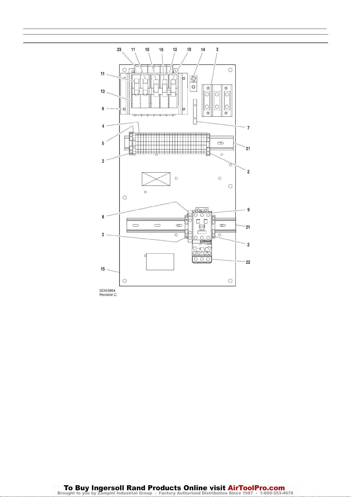
INTELLISYS PARTS – C37 FULL VOLTAGE – DOL 60Hz – 575V 15/30hp
INTELLISYS OPTION
Item ccn Qty. Description Item ccn Qty. Description
1–
2 39252937 4 Block, end stop
3 39164520 1 Block, terminal
4 39252903 27 Block, terminal
5 39252911 1 Block, terminal ground
6 22114623 1 Bracket
7 32342115 1 Bus, grounding
8 22132963 1 Contact, auxilliary
9 39251061 1 Contactor – C37
10 22074033 3 Fuse
2.0A 125–250V
11 32342099 2 Fuse
1.5A 600V
12 39479035 1 Fuse, holder
13 39480504 1 Fuse, holder
14 32342123 1 Lug, power grounding
15 22113351 1 Panel
*16 39191648 1 Plug
11 position
*17 39191655 1 Plug
16 position
*18 39186101 1 Plug
4 position
*19 39191630 1 Plug
5 position
*20 39186093 1 Plug
6 position
21 22056741 2 Rail
22 23053754 1 Relay, overload
23 39491519 1 Transformer
* Not illustrated
Page 23
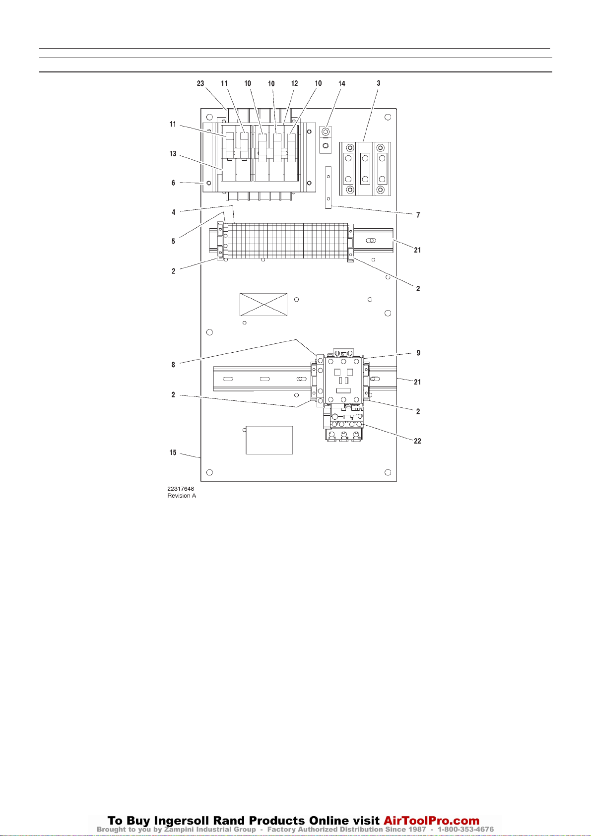
INTELLISYS PARTS – C43 FULL VOLTAGE – DOL 60Hz – 230/460V 15hp
http:/air.ingersollrand.com
UP6 15, UP6 20, UP6 25, UP6 30
INTELLISYS OPTION
21
Item ccn Qty. Description Item ccn Qty. Description
1–
2 39252937 4 Block, end stop
3 39164520 1 Block, terminal
4 39252903 27 Block, terminal
5 39252911 1 Block, terminal ground
6 22114623 1 Bracket
7 32342115 1 Bus, grounding
8 22132963 1 Contact, auxilliary
9 39250998 1 Contactor – C43
10 22074033 3 Fuse
2.0A 125–250V
11 32342099 2 Fuse
1.5A 600V
12 39479035 1 Fuse, holder
13 39480504 1 Fuse, holder
14 32342123 1 Lug, power grounding
15 22113351 1 Panel
*16 39191648 1 Plug
11 position
*17 39191655 1 Plug
16 position
*18 39186101 1 Plug
4 position
*19 39191630 1 Plug
5 position
*20 39186093 1 Plug
6 position
21 22056741 2 Rail
22 23053754 1 Relay, overload
23 39491519 1 Transformer
* Not illustrated
Page 24
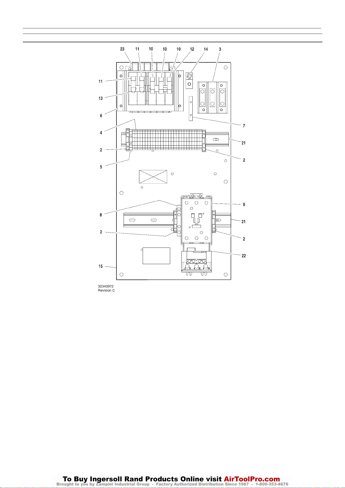
22
UP6 15, UP6 20, UP6 25, UP6 30
http:/air.ingersollrand.com
INTELLISYS PARTS – C85 FULL VOLTAGE – DOL 60Hz – 200V 15–25hp / 230/460 20–30hp
INTELLISYS OPTION
Item ccn Qty. Description Item ccn Qty. Description
1–
2 39252937 4 Block, end stop
3 39164520 1 Block, terminal
4 39252903 27 Block, terminal
5 39252911 1 Block, terminal ground
6 22114623 1 Bracket
7 32342115 1 Bus, grounding
8 22132963 1 Contact, auxilliary
9 39251020 1 Contactor – C85
10 22074033 3 Fuse
2.0A 125–250V
11 32342099 2 Fuse
1.5A 600V
12 39479035 1 Fuse, holder
13 39480504 1 Fuse, holder
14 32342123 1 Lug, power grounding
15 22113351 1 Panel
*16 39191648 1 Plug
11 position
*17 39191655 1 Plug
16 position
*18 39186101 1 Plug
4 position
*19 39191630 1 Plug
5 position
*20 39186093 1 Plug
6 position
21 22056741 2 Rail
22 23053770 1 Relay, overload
23 39491519 1 Transformer
* Not illustrated
Page 25
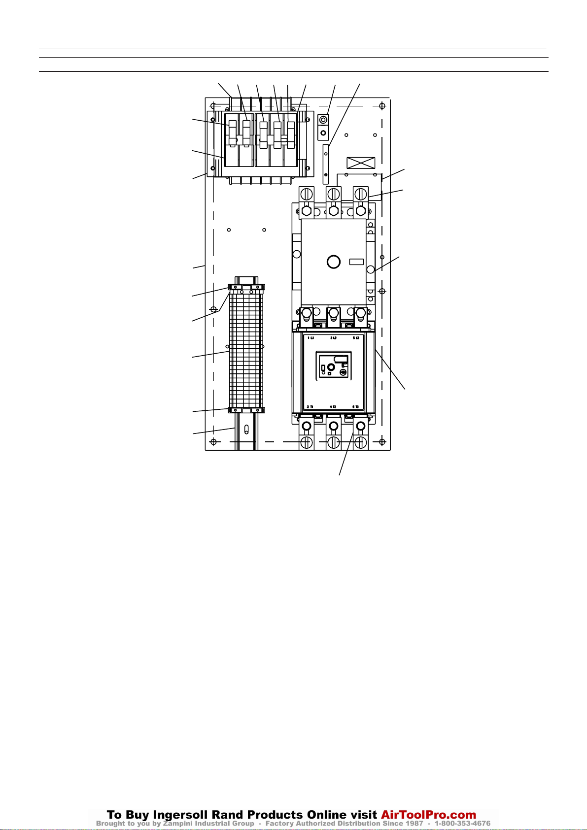
INTELLISYS PARTS – D110 FULL VOLTAGE – DOL 60Hz – 200V 30hp
http:/air.ingersollrand.com
UP6 15, UP6 20, UP6 25, UP6 30
10
24
10
12
6
16
2
9
9
9
INTELLISYS OPTION
11
7
15
13
5
8
23
3
4
23
2
22
Revision D
Item ccn Qty. Description Item ccn Qty. Description
*1 22113344 1
2 39252937 2 Block, end stop
3 39252937 1 Block, terminal ground
4 39252903 27 Block, terminal
5 22630727 1 Kit, terminal
6 22114623 1 Bracket
7 32342115 1 Bus, grounding
8 22264873 1 Contactor – D110
9 22074033 3 Fuse
10 32342099 2 Fuse
11 39479035 1 Fuse, holder
12 39480504 1 Fuse, holder
13 1 Label
Assembly, emergency stop
push button
2.0A 125–250V
1.5A 600V
532343980
*14 39191648 1 Plug
11 pos ition
15 32342123 1 Lug, power grounding
16 22050140 1 Panel
11 pos ition
*17 39191655 1 Plug
16 position
*18 39186101 1 Plug
4position
*19 39191630 1 Plug
5position
*20 39186093 1 Plug
6position
22 22056741 1 Rail
23 39251095 1 Relay,overload
24 39491519 1 Transformer
* Not illustrated
Page 26
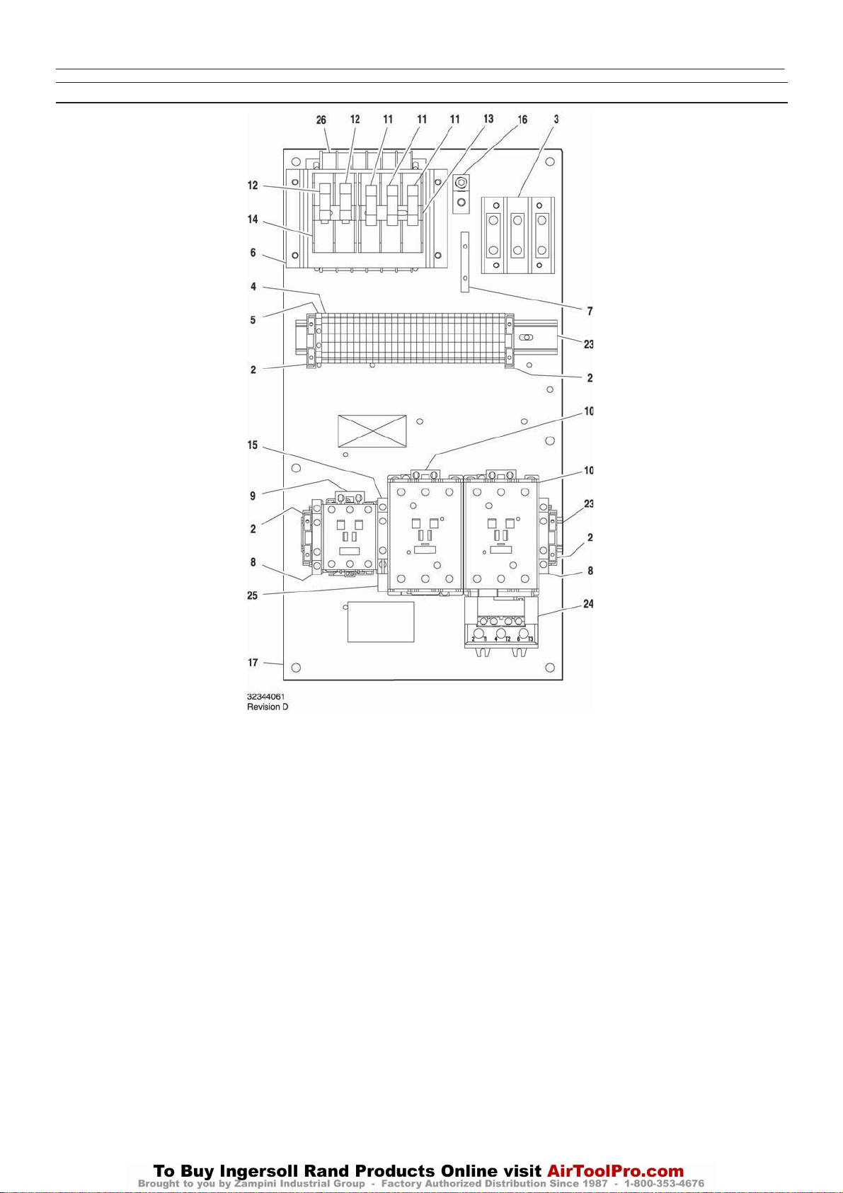
24
UP6 15, UP6 20, UP6 25, UP6 30
http:/air.ingersollrand.com
INTELLISYS PARTS – C60/C43 STAR/DELTA – 60Hz – 200V 25/30hp, 220/230V – 30hp
INTELLISYS OPTION
Item ccn Qty. Description Item ccn Qty. Description
1–
2 39252937 4 Block, end stop
3 39164520 1 Block, terminal
4 39252903 29 Block, terminal
5 39252911 1
6 22114623 1 Bracket
7 32342115 1 Bus, grounding
8 22132963 2 Contact, auxilliary
9 39250998 1 Contactor – C43
10 39251004 2 Contactor – C60
11 22074033 3 Fuse
12 32342099 2 Fuse
13 39479035 1 Fuse, holder
14 39480504 1 Fuse, holder
15 39333257 1 Interlock
Block, terminal ground
2.0A 125–250V
1.5A 600V
16 32342123 1 Lug, power grounding
17 22113351 1 Panel
*18 39191648 1 Plug
11 position
*19 39191655 1 Plug
16 position
*20 39186101 1 Plug
4 position
*21 39191630 1 Plug
5 position
*22 39186093 1 Plug
6 position
23 22056741 2 Rail
24 23053770 1 Relay, overload
25 39203443 1 Suppressor
26 39491519 1 Transformer
* Not illustrated
Page 27
INTELLISYS OPTION
http:/air.ingersollrand.com
UP6 15, UP6 20, UP6 25, UP6 30
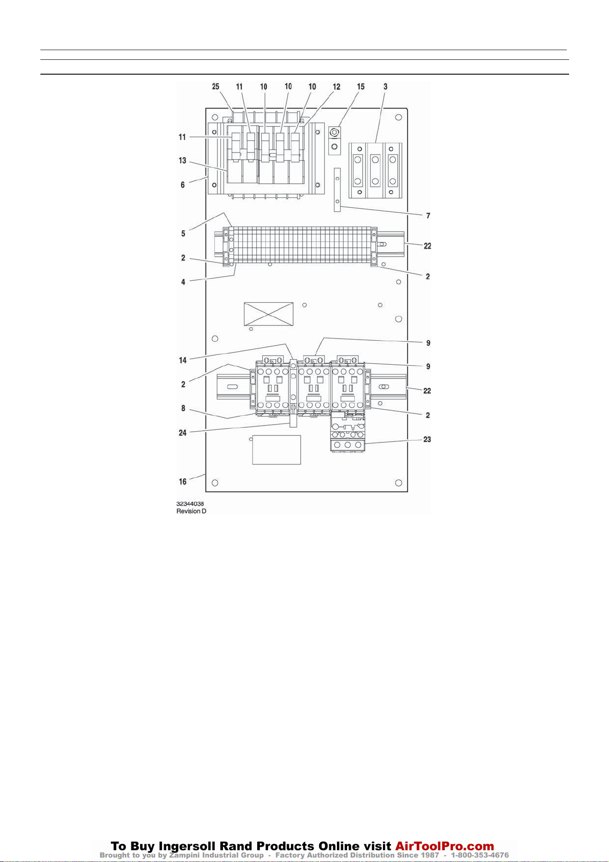
INTELLISYS PARTS – C23/16 STAR/DELTA – 60Hz – 440/460V – 20/25hp, 575V – 25/30hp
25
Item ccn Qty. Description Item ccn Qty. Description
1–
2 39252937 4 Block, end stop
3 39164520 1 Block, terminal
4 39252903 30 Block, terminal
5 39252911 1 Block, terminal ground
6 22114623 1 Bracket
7 32342115 1 Bus, grounding
8 22074413 1 Contactor – C16
9 39252036 2 Contactor – C23
10 22074033 3 Fuse
2.0A 125–250V
11 32342099 2 Fuse
1.5A 600V
12 39479035 1 Fuse, holder
13 39480504 1 Fuse, holder
14 39333257 1 Interlock
15 32342123 1 Lug, power grounding
16 22113351 1 Panel
*17 39191648 1 Plug
11 position
*18 39191655 1 Plug
16 position
*19 39186101 1 Plug
4position
*20 39191630 1 Plug
5position
*21 39186093 1 Plug
6position
22 22056741 2 Rail
23 23053747 1 Relay, overload
24 39203443 1 Suppressor
25 39491519 1 Transformer
* Not illustrated
Page 28
26
UP6 15, UP6 20, UP6 25, UP6 30
http:/air.ingersollrand.com
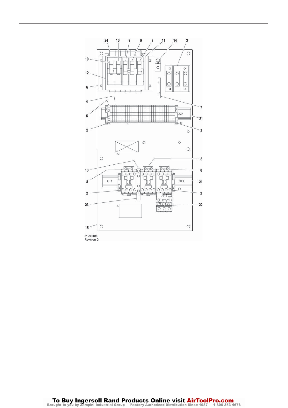
INTELLISYS PARTS – C23/23 STAR/DELTA – 60Hz – 380V 20hp
INTELLISYS OPTION
Item ccn Qty. Description Item ccn Qty. Description
1–
2 39252937 4 Block, end stop
3 39164520 1 Block, terminal
4 39252903 30 Block, terminal
5 39252911 1 Block, terminal ground
6 22114623 1 Bracket
7 32342115 1 Bus, grounding
8 39252036 3 Contactor – C23
9 22074033 3 Fuse
2.0A 125–250V
10 32342099 2 Fuse
1.5A 600V
11 39479035 1 Fuse, holder
12 39480504 1 Fuse, holder
13 39333257 1 Interlock
14 32342123 1 Lug, power grounding
15 22113351 1 Panel
*16 39191648 1 Plug
11 position
*17 39191655 1 Plug
16 position
*18 39186101 1 Plug
4position
*19 39191630 1 Plug
5position
*20 39186093 1 Plug
6position
21 22056741 2 Rail
22 23053747 1 Relay, overload
23 39203443 1 Suppressor
24 39313143 1 Transformer
* Not illustrated
Page 29
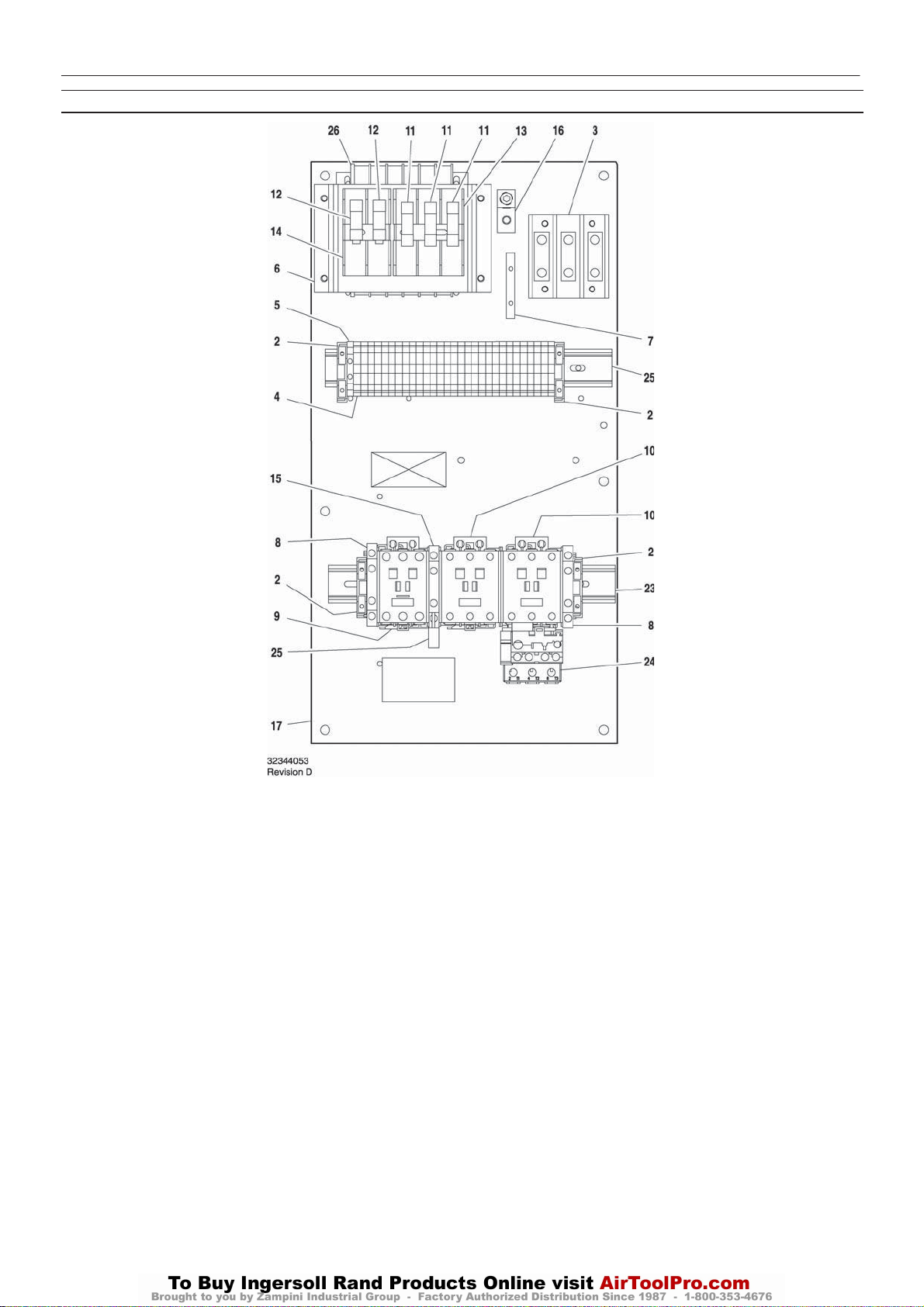
INTELLISYS PARTS – C43/37 STAR/DELTA – 60Hz – 200V 20hp, 220/230V – 25hp
http:/air.ingersollrand.com
UP6 15, UP6 20, UP6 25, UP6 30
INTELLISYS OPTION
27
Item ccn Qty. Description Item ccn Qty. Description
1–
2 39252937 4 Block, end stop
3 39164520 1 Block, terminal
4 39252903 29 Block, terminal
5 39252911 1 Block, terminal ground
6 22114623 1 Bracket
7 32342115 1 Bus, grounding
8 22132963 2 Contact, auxilliary
9 39251061 1 Contactor – C37
10 39250998 2 Contactor – C43
11 22074033 3 Fuse
2.0A 125–250V
12 32342099 2 Fuse
1.5A 600V
13 39479035 1 Fuse, holder
14 39480504 1 Fuse, holder
15 39333257 1 Interlock
16 32342123 1 Lug, power grounding
17 22113351 1 Panel
*18 39191648 1 Plug
11 position
*19 39191655 1 Plug
16 position
*20 39186101 1 Plug
4position
*21 39191630 1 Plug
5position
*22 39186093 1 Plug
6position
23 22056741 2 Rail
24 23053754 1 Relay, overload
25 39203443 1 Suppressor
26 39491519 1 Transformer
* Not illustrated
Page 30

28
UP6 15, UP6 20, UP6 25, UP6 30
http:/air.ingersollrand.com
INTELLISYS PARTS – C37/23 STAR/DELTA – 60Hz – 220/230V – 15–20hp, 440/460V – 30hp
INTELLISYS OPTION
Item ccn Qty. Description Item ccn Qty. Description
1–
2 39252937 4 Block, end stop
3 39164520 1 Block, terminal
4 39252903 29 Block, terminal
5 39252911 1 Block, terminal ground
6 22114623 1 Bracket
7 32342115 1 Bus, grounding
8 22132963 1 Contact, auxilliary
9 39252036 1 Contactor – C23
10 39251061 2 Contactor – C37
11 22074033 3 Fuse
2.0A 125–250V
12 32342099 2 Fuse
1.5A 600V
13 39479035 1 Fuse, holder
14 39480504 1 Fuse, holder
15 39333257 1 Interlock
16 32342123 1 Lug, power grounding
17 22113351 1 Panel
*18 39191648 1 Plug
11 position
*19 39191655 1 Plug
16 position
*20 39186101 1 Plug
4position
*21 39191630 1 Plug
5position
*22 39186093 1 Plug
6position
23 22056741 2 Rail
24 23053754 1 Relay, overload
25 39203443 1 Suppressor
26 39491519 1 Transformer
220/230V & 440/460V
* Not illustrated
Page 31
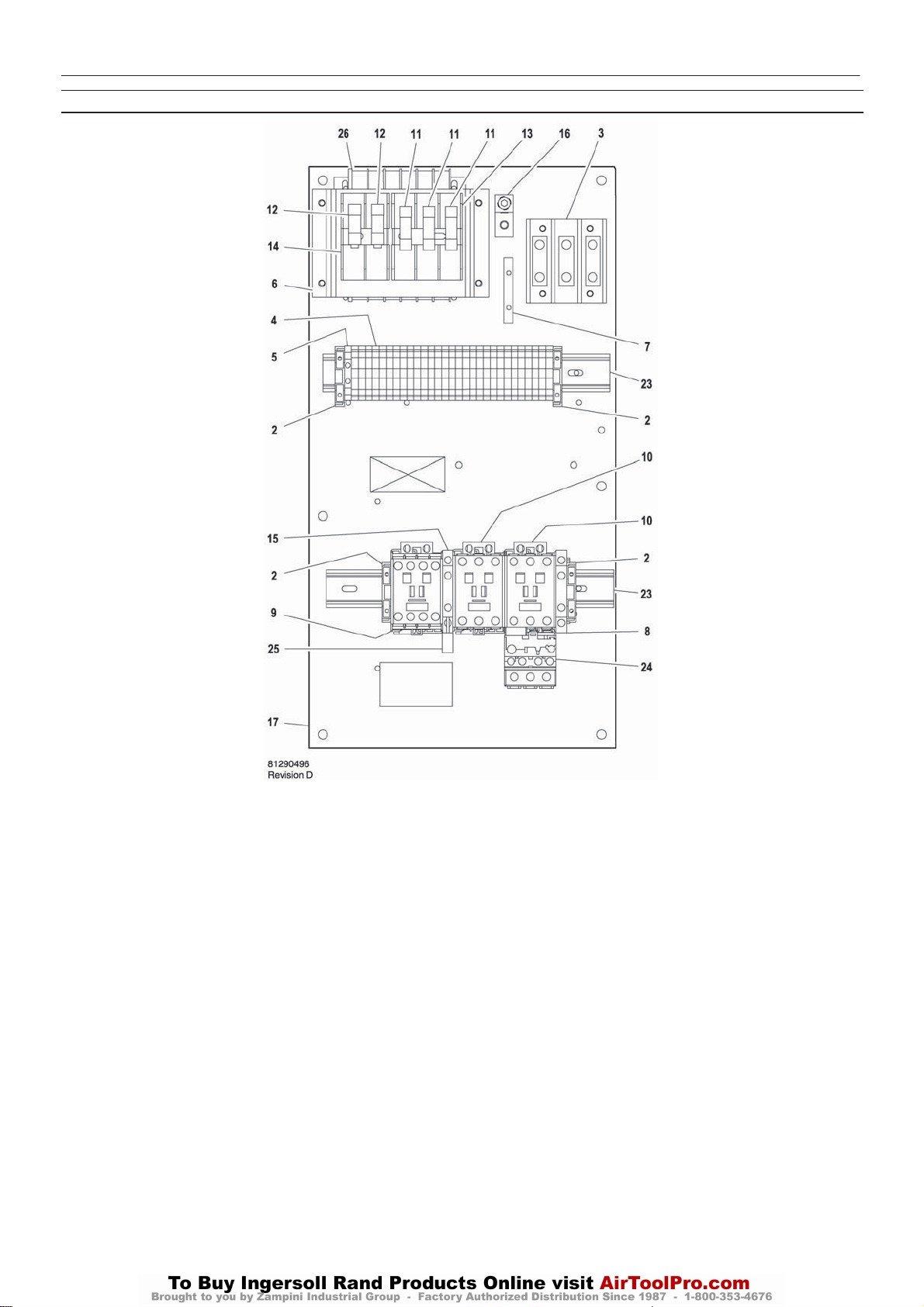
INTELLISYS PARTS – C37/23 STAR/DELTA – 60Hz – 380V – 25/30hp
http:/air.ingersollrand.com
UP6 15, UP6 20, UP6 25, UP6 30
INTELLISYS OPTION
29
Item ccn Qty. Description Item ccn Qty. Description
1–
2 39252937 4 Block, end stop
3 39164520 1 Block, terminal
4 39252903 29 Block, terminal
5 39252911 1 Block, terminal ground
6 22114623 1 Bracket
7 32342115 1 Bus, grounding
8 22132963 1 Contact, auxilliary
9 39252036 1 Contactor – C23
10 39251061 2 Contactor – C37
11 22074033 3 Fuse
2.0A 125–250V
12 32342099 2 Fuse
1.5A 600V
13 39479035 1 Fuse, holder
14 39480504 1 Fuse, holder
15 39333257 1 Interlock
16 32342123 1 Lug, power grounding
17 22113351 1 Panel
*18 39191648 1 Plug
11 position
*19 39191655 1 Plug
16 position
*20 39186101 1 Plug
4position
*21 39191630 1 Plug
5position
*22 39186093 1 Plug
6position
23 22056741 2 Rail
24 23053754 1 Relay, overload
25 39203443 1 Suppressor
26 39313143 1 Transformer
380V
* Not illustrated
Page 32
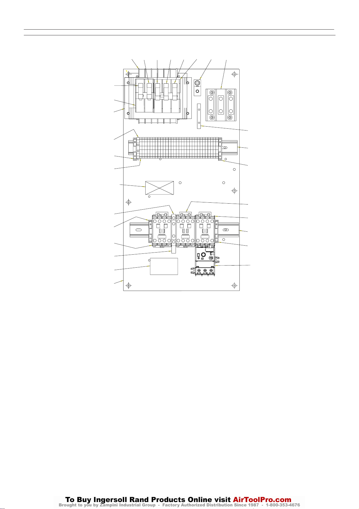
30
UP6 15, UP6 20, UP6 25, UP6 30
http:/air.ingersollrand.com
ASSEMBLY, STARTER C23/C16 60Hz SD (INTELLISYS) 575V
INTELLISYS OPTION
12
10
5
4
24
2
I-R PART
NUMBER AND
REV LEVEL
13
24
7
25
14
26
12
11
11
11
3
15
9
6
22
24
8
8
22
24
23
22650550
Revision B
Item ccn Qty. Description Item ccn Qty. Description
1 - - -
2 39252903 30 Block, Terminal
3 39164520 1 Block, Terminal
4 39252911 1 Block, Terminal GND.
5 22114623 1 Bracket, Fuse Block
6 32342115 1 Bus, Grounding
7 22074413 1 Contactor, C16
8 39252036 2 Contactor, C23
9 39479035 1 Fuse, Holder
10 39480504 1 Fuse, Holder
11 22074033 3 Fuse, 125-250V 2.0A
12 32342099 2 Fuse, 600V 1.5A Primary
13 39333257 1 Interlock, Mechanical
14 1 Label,UL&CUL
16
15 32342123 1 Lug, Grounding
16 22113351 1 Panel
17 39191648 1 Plug, 11 Position
18 39191655 1 Plug, 16 Position
19 39186101 1 Plug, 4 Position
20 39191630 1 Plug, 5 Position
21 39186093 1 Plug, 6 Position
22 22056741 2 Rail, Din
23 23053739 1 Relay, Overload
24 39252937 4 Stop, Din Rail
25 39203443 1 Suppressor, Arc
26 39491519 1 Transformer, Control Multi-
Page 33
DRYER OPTION
http:/air.ingersollrand.com
UP6 15, UP6 20, UP6 25, UP6 30
31
The UP series integrated dryer is not for use with the low ambient
or outdoor module options.
INSTALLATION
a) Do not obstruct the dryer air grilles.
b) Allow sufficient gap around the unit to facilitate maintenance and
ensure unimpeded air discharge from the condenser.
c) Avoid recirculation of hot condenser air back into the condenser air
inlet.
d) Do not connect condensate drains common to other pressurized
drain lines in a closed circuit. Make sure the outflow from the condensate
drains is unimpeded. Connect the condensate piping in such a way to
ensure that sound levels are kept to a minimum during drainage.
Ensure that all condensate is disposed of in a responsible manner, in
accordance with local norms concerning environmental protection.
e) The ambient air around the dryer and compressor must not contain
solid or gaseous contaminants. All compressed and condensed gases
can generate acids or chemical products which may damage the
compressor or components inside the dryer.
Take particular care with sulphur, ammonia, chlorine and installations in
marine environments. For further advice or assistance consult your local
Ingersoll Randrepresentative.
ELECTRICAL CONNECTION
The dryer is powered from single–phase that must be supplied
separately from the compressor three–phase supply. The dryer should
be connected to a single phase supply in accordance with local
requirementsand codes.
CONDENSATE DRAINS
The dryer package is equipped with three automatic condensate float
drains in the moisture separator, the dryer’s compressor, and the
post–filter. Each float drain has a drainage port near the compressed air
outlet on the package.
THESE LINES MUST BE KEPT SEPARATE. Joining them will cause
improper operation.
START–UP AND OPERATION
Preliminary checks
Before starting the compressor, make sure that:
The power supply is correct for the dryer voltage.
Starting the dryer
a) Use the green switch to start the dryer (Fig.2b).
b) To protect dryer equipment, always start up the dryer before
activating the air compressor.
c) Wait about 5 minutes until the dryer is running at the correct operating
temperaturesand pressures before starting the compressor.
d) Always leave the dryer running while the air compressor is operating,
irrespective of load condition.
After stopping the dryer, wait at least 3 minutes before starting it again.
STOPPING THE DRYER
a) Use the switch to stop the dryer (Fig.2b).
b) Stop the dryer at least 2 minutes after shutting down the air
compressor or interrupting the air flow to the dryer.
Compressed air must never enter the dryer when the dryer is switched
off or when it is in an alarm situation which stops the refrigeration
compressor. The dryer can be bypassed in these conditions.
OPERATION
The dryer operates automatically. It is factory set for a dew point of
37 F(3C) (ISO7183, Part 2) and therefore requires no further
calibration.
For maximum performance from your dryer, follow the maintenance
schedule.
The dewpoint thermometer gives an indication of performance of the
dryer. When the dryer is switched off at ambient conditions, it displays
red. In normal conditions it should be operating in the green region. If the
unit continues to operate in the red region, contact your local
Ingersoll Randrepresentative.
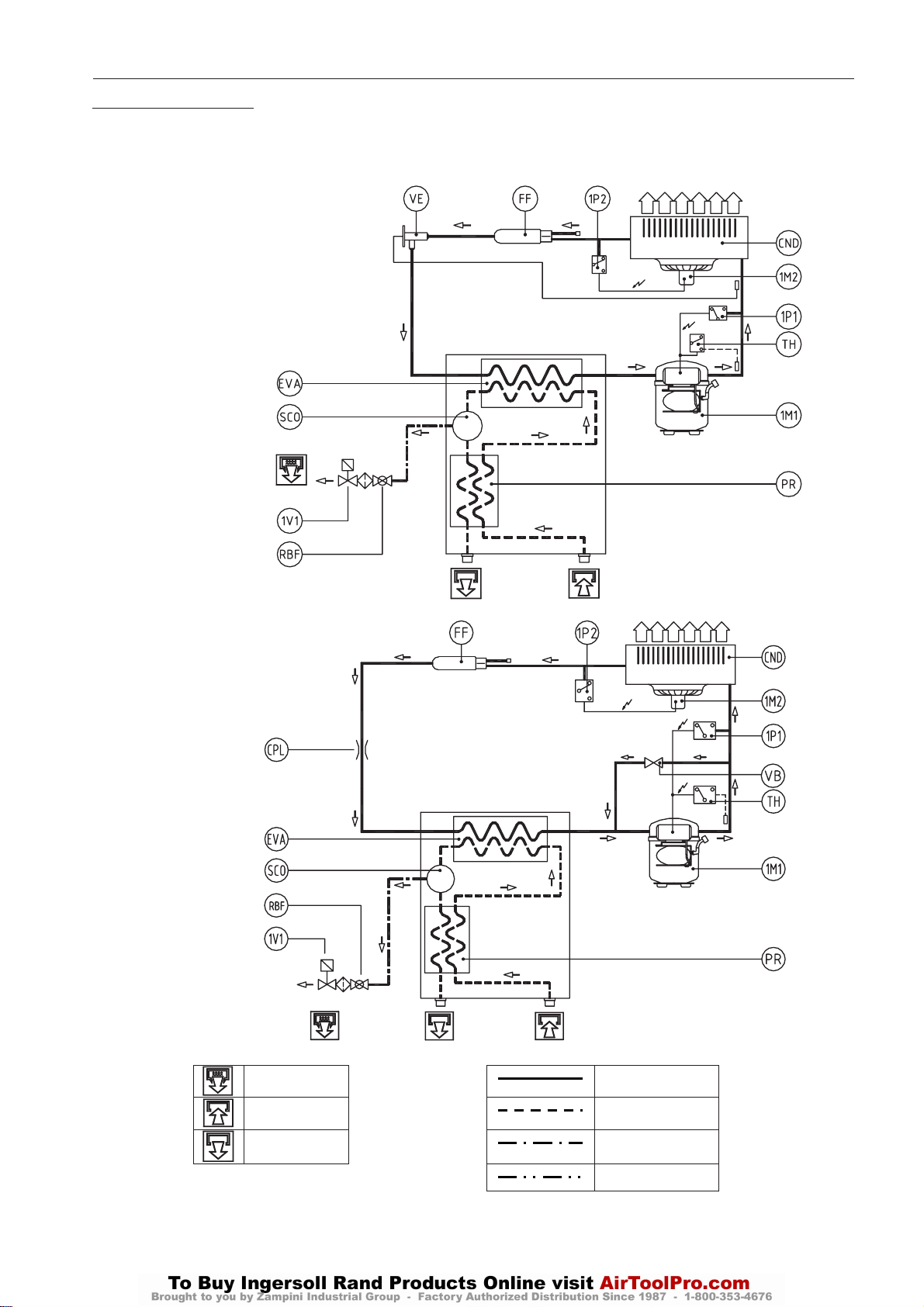
Fig.1 shows the dryer’s refrigeration and air circuits.
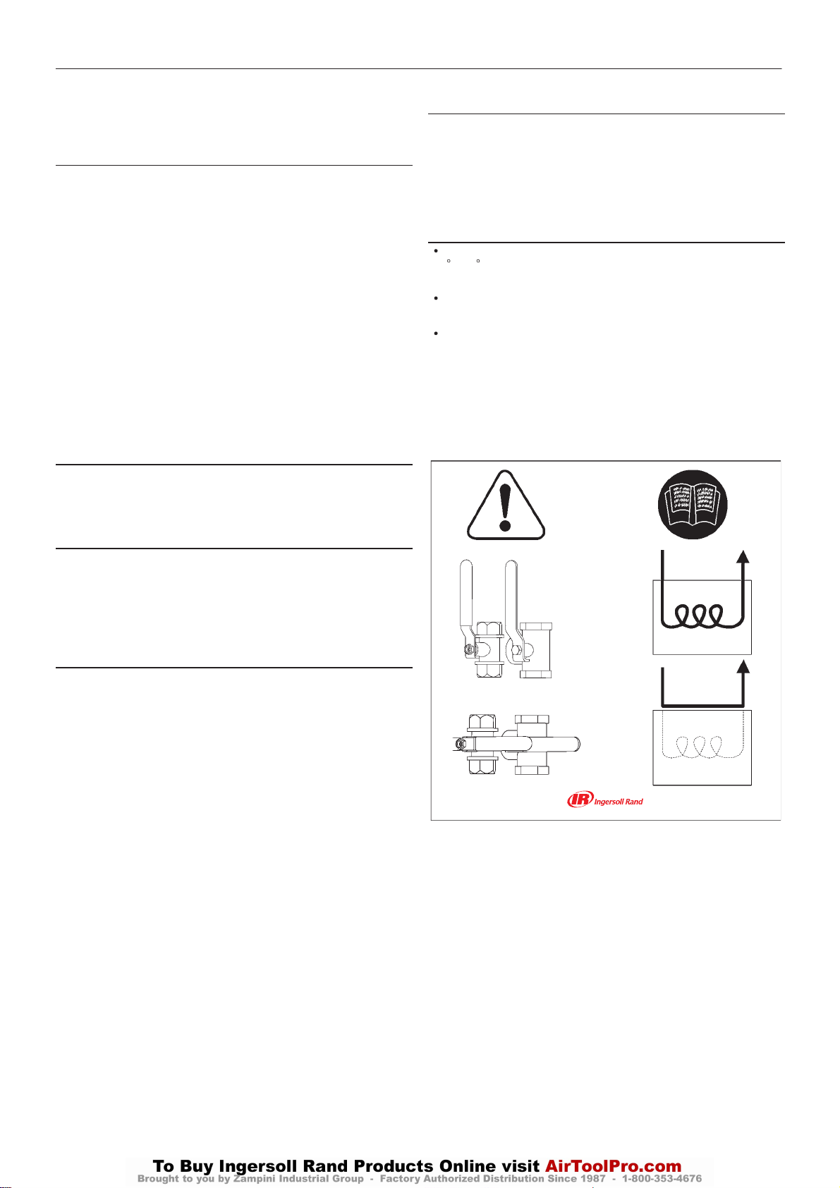
In order to bypass the dryer, stop the UP compressor and lock and tag
it out. Turn BOTH valves to a horizontal position, as shown. The
compressor can be run and the dryer can be removed from the system
for repair in bypass mode.
Do not operate with valves in positions other than those shown here. This
may pressurize dryer with no air flow.
Page 34
32
UP6 15, UP6 20, UP6 25, UP6 30
http:/air.ingersollrand.com
DRYER OPTION
MAINTENANCE
Before accessing live electrical parts, disconnect the power supply to the
dryer using disconnect switch or disconnect the cable connections.
Preventive maintenance
For optimum performance from your dryer, follow the periodic
maintenanceschedule described below.
WEEKLY
CONDENSATE DRAINS
Verify that the condensate drains
are operating correctly.
MONTHLY
COMPRESSOR
Make sure the refrigerant
compressor temperature is below
140 F (60 C) when running.
EVERY 4 MONTHS
CONDENSER
Remove any dust from the
condenser fins.
COMPRESSOR
Make sure compressor power
consumption complies with data
plate specifications.
YEARLY
CONDENSATE DRAINS
Completely disassemble the
drains and clean all their
components.
AIR FILTER
Replace air filter element.
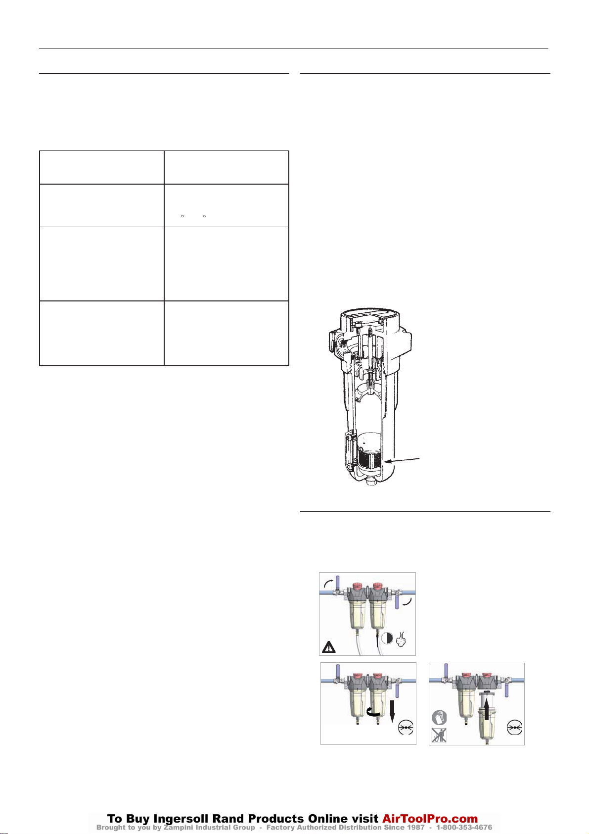
MOISTURE SEPARATOR MAINTENANCE
The moisture separator will operate indefinitely under normal working
conditions, however at some time it may be necessary to replace the
seals should the housing leak.
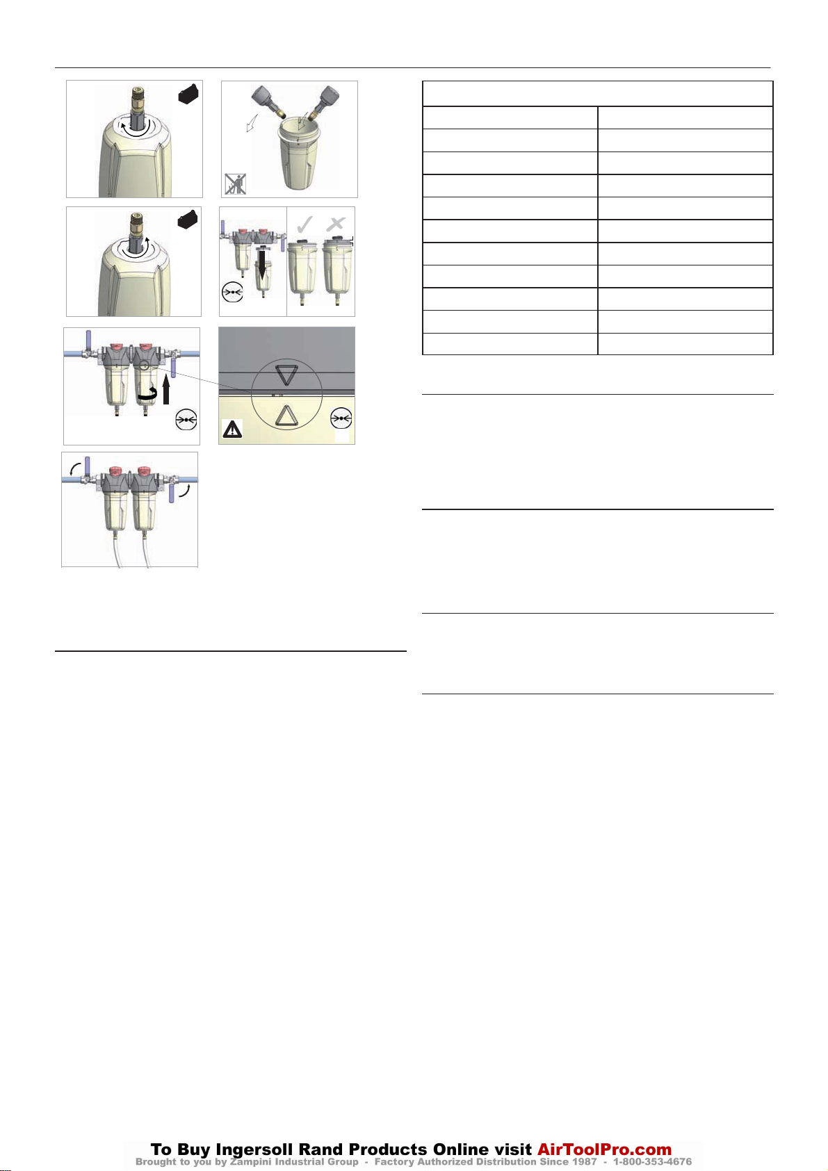
1. Isolate the housing from the air supply.
2. Fully depressurize in drain bowl as appropriate.
3. Unscrew bowl and remove. If pressure has not been completely
released from the housing, air will escape from the warning hole giving
an audible alarm. Screw back bowl and repeat instruction 2 before
attempting again. Should resistance to unscrewing be experienced,
provision is made for a ’C’ spanner to fit onto the ribs of the bowl.
4. Check condition of bowl seal and replace if necessary. Clean screw
threads.
5. The autodrain assembly is not serviceable and must be replaced if
faulty.
6. Refit bowl with ’O’ ring seal.
7. Repressurize and check for leaks. If leaks occur they will most
probably be from the bowl ’O’ ring. Depressurize housing and remove ’O’
ring as stated above and inspect and clean. Ensure that mating surfaces
are clean and then refit ’O’ ring and repressurize.
Auto – drain assembly
AIR FILTER MAINTENANCE
In order to ensure optimum compressed air quality the filter element
should be replaced as follows. (Used filter elements must be disposed
of in accordance with local regulations.)
Use only genuine Ingersoll Rand replacement elements.
2
1
2
3
> 30s
0 bar
0 psi
5
0 bar
0 psi
4
2
1
Page 35
DRYER OPTION
http:/air.ingersollrand.com
UP6 15, UP6 20, UP6 25, UP6 30
33
5 6
1
7 8
0 bar
0psi
9 10
2
1
0 bar
0psi
12
1
2
0 bar
0psi
DISASSEMBLING THE UNIT
The unit has been designed and constructed to guarantee continuous
operation.
The long service life of some components such as the fan and
compressor depends on good maintenance.
The unitmustonlybedisassembled by a refrigerant specialist.
Refrigerant liquid and lubricating oil inside the refrigeration circuit must
be recovered in compliance with current norms in the country where the
machine is installed.
RECYCLING DISASSEMBLY
Frame and panels
Heat exchanger (cooler) Copper
Pipes Copper
Drainage system Polyamide
Heat exchanger insulation EPS (polystyrene sintered)
Pipe insulation Gum synthetic
Compressor Steel / copper / aluminium / oil
Condenser Steel / copper / aluminium
Refrigerant
Valve Brass
Electrical cable Copper / PVC
REFRIGERANT LEAKS IN THE REFRIGERATION CIRCUIT
The unit isdispatched in perfect working order, already charged.
Refrigerant leaks may be identified by tripping of the compressor
overload protector (SK).
IF A LEAK IS DETECTED IN THE REFRIGERANT CIRCUIT, SEEK
TECHNICAL ASSISTANCE.
REFRIGERANT CHARGING
THIS OPERATION MUST ONLY BE PERFORMED BY A
REFRIGERANT SPECIALIST.
WHEN REPAIRING THE REFRIGERANT CIRCUIT, COLLECT ALL
THE REFRIGERANT IN A CONTAINER AND DISPOSE OF IT IN THE
APPROPRIATE MANNER.
CHARACTERISTICS OF REFRIGERANT R134A
In normal temperature and pressure conditions the above refrigerant is
a colorless, class A1/A1 gas with TVL value of 1000ppm (ASHRAE
classification).
If a refrigerant leak occurs, thoroughly air the room before commencing
work.
Steel / epoxy resin polyester
R134a
Page 36
34
UP6 15, UP6 20, UP6 25, UP6 30
http:/air.ingersollrand.com
DRYER OPTION
REFRIGERANT CIRCUIT
Cod. 713.0007.13.00 – Rev. 00
Model UP6 15-20 HP
UP5 11-15 KW
Cod. 713.0057.07.00 – Rev. 00
Model UP6 25-30 HP
UP5 18-22 KW
Condensate drain Refrigerant line
Air inlet Compressed air line
Air outlet Condensate drain line
Equalization line
Page 37
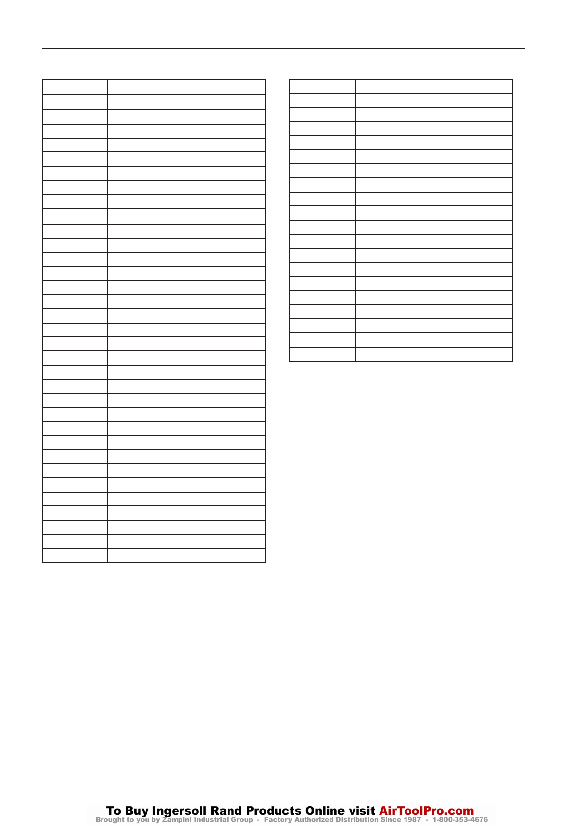
LEGEND
http:/air.ingersollrand.com
UP6 15, UP6 20, UP6 25, UP6 30
DRYER OPTION
35
Pos.
1A1 Electronic Controller
1B1 Drain solenoid valve coil
1M1 Refrigerant compressor
1M2 Fan Motor
1P1 High pressure Switch
1P2 Fan pressure Switch
1Q1 Compressor circuit breaker
1Q2 Fan circuit breaker
1S1 Main power switch
1S2 Plug
1T1 Transformer
1V1 Solenoid drain Valve
CB Compressor box
CBL Cables
CND Condenser
CNV Fan capacitor
CPL Capillary tube
EB Electrical box
ED 10 micron lter element
EH 0.01 micron lter element
EP 1 micron lter element
EQ 5 micron lter element
EVA Evaporator
F1-F2 Fuses
FD Air lter 10 micron
FF Filter dryer
FH Air lter 0.01 micron
FP Air lter 1 micron
FQ Air lter 5 micron
FR Drain screen
FV Fan motor fuse
GGrid
IM Moisture indicator
DESCRIPTION
K1 Contactor switch
K2 Fan contactor switch
PCP Thermal protection
PR Air-air heat exchanger
PSC Air-air heat exchanger (D__IT)
RBF Tap with strainer
RR Rotalock cock
RT1 - RT4 Temperature probes
SC Heat exchanger base
SCO Condensate separator
SLI Liquid separator
SSC Condensate drain
TEMP Time setter
TH Time setter
TLT Remote cont. Thermostat
VB By-pass hot gas valve
VE Expansion valve
VNR One way valves with strainer
VT Fan blade
X1-X2, X3-XM Terminal blocks
Page 38
36
UP6 15, UP6 20, UP6 25, UP6 30
http:/air.ingersollrand.com
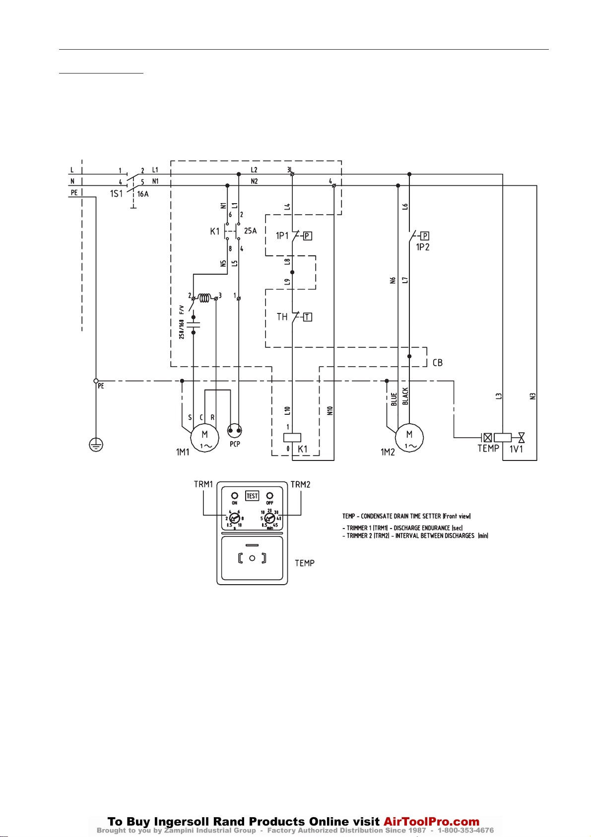
WIRING DIAGRAM
Cod. 714.0172.01.00 – Rev. 00
Models UP615 – 30 HP (115V/1Ph/60Hz)
DRYER OPTION
μ
Page 39
DRYER OPTION
http:/air.ingersollrand.com
UP6 15, UP6 20, UP6 25, UP6 30
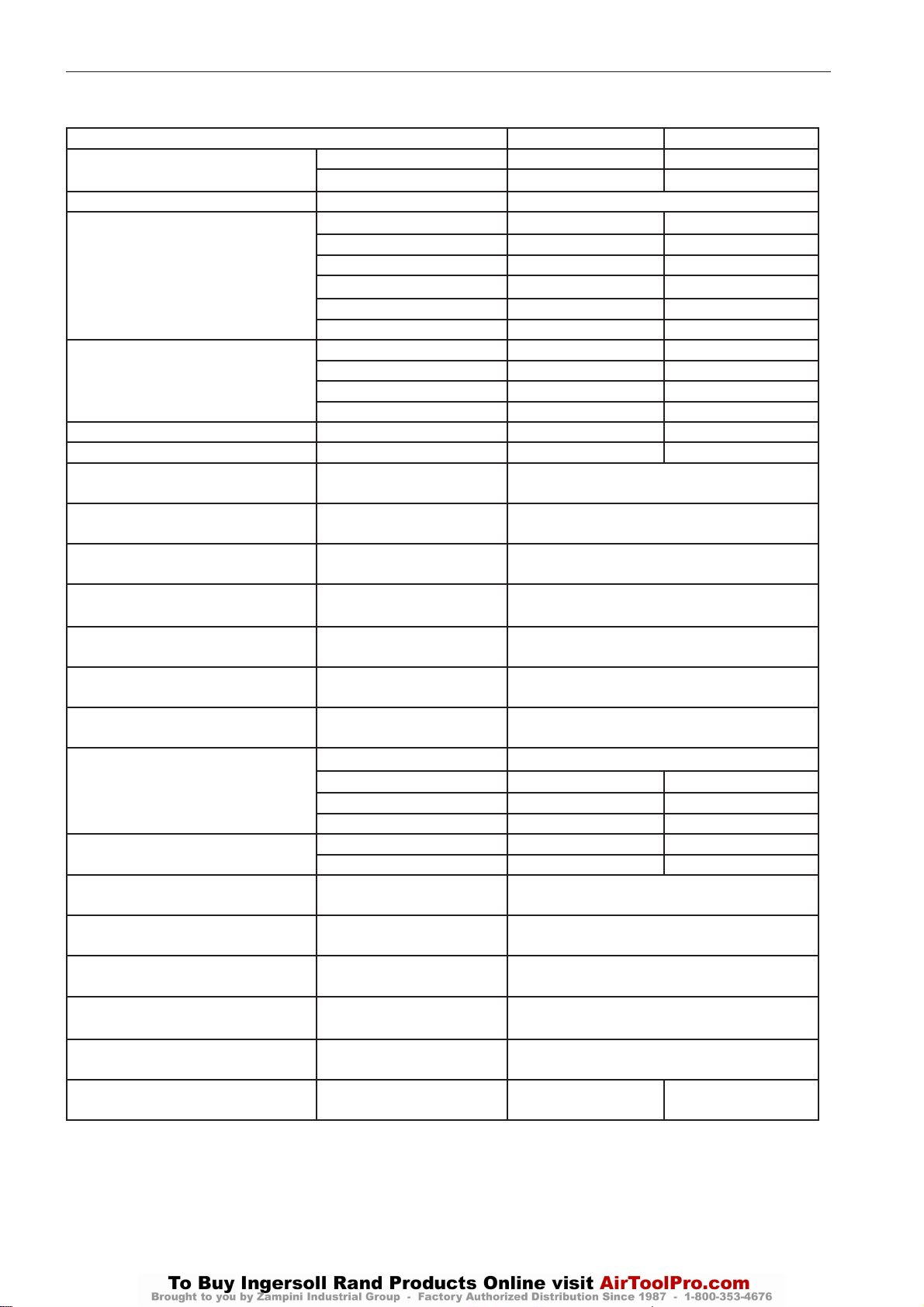
DATA SHEET
MODEL UP6 15-20 HP UP6 25-30 HP
AR
AIR FLOW RATE*
POW SUPPY VOLT/PH/HZ 115/1/60
1M1
COMPRESSOR
1M2
FAN MOTOR
TOTAL A A 9.2 11.3
CONNECTION NPT 3/4” 3/4”
AIR T °F
AIR T MAX °F
AMB T °F
AMB T MIN-MAX °F
AIR W PRESS psi
AIR PRESS MAX psi
DEW POINT* °F
REF.
REFRIGERANT
W
WEIGHT
EVAP. TEMP.* °F
SUCTION TEMP.* °F
DISCH. PRESS.* psig
HP SWITCH SETTING psig
FAN SWITCH SETTING psig
THERMOSTAT SWITCH
SETTING
CFM 83 125
m3/h 140 212
HP 2/3 3/4
kW 0.71 0.83
Max kW 1.14 1.37
RLA 8.16 9.69
FLA 11.6 14
LRA 46 54
QTY 1 1
HP 1/46 1/20
RLA 1.00 1.60
LRA 1.36 2.10
104
°C
°C
°C
°C
bar
bar
°C
TYPE R134a
LB 0.99 1.65
OZ 15.9 26.46
KG 0.45 0.75
LB 138 147
KG 63 67
°C
°C
Bar
Bar
Bar
°F
°C
212
100
40
162
72
77
25
36 – 122
2 – 50
123
8.5
203
14
< 50 (ISO CLASS 6)
< 10 (ISO CLASS 6)
37 – 41
3 – 5
39 – 64
4 – 18
170 - 230
12 – 16
435
30
123 – 160
8,5 – 11
37
239
115
*Rating conditions of: 40°C (104°F) and 123 psig Ai r Inlet, 25°C (77°F) Ambient temperature
*Conditions de fonctionnement de: 40°C (104°F) et 1 23 psig air en entrée, 25°C (77°F) température ambi ant
Performance and specications - Performances et caractéristiques techniques + / -5%
Page 40
38
UP6 15, UP6 20, UP6 25, UP6 30
http:/air.ingersollrand.com
DRYER OPTION
LEGEND
POS.
AR Air ow rate
POW SUPPY Power supply
HP Nominal power
kW Nominal consumption
Max kW Full load consumption
RLA Nominal Current
FLA Full load current
LRA Locked rotor current
TOTAL A Total current
CONNECTION Air connections
AIR T Air inlet temperature
AIR T MAX Max. air inlet temperature
AMB T Ambient temperature
AMB T MIN-MAX Min-Max. ambient
AIR W PRESS Air working pressure
DESCRIPTION
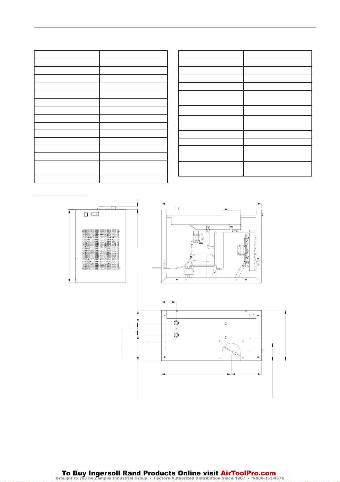
DRYER DIMENSIONS
temperature
POS.
AIR PRESS MAX Max. air pressure
DEWP Pressure dew point
REF. Refrigerant
MAX FUSE Max fuse size
MINCIRCUIT
AMPACITY
W Weight
EVAP. TEMP. Evaporation
SUCTION TEMP. Suction Temperature
DISCH. PRESS. Discharge Pressure
HP SWITCH SETTING High pressure switch
THERMOSTAT SWITCH
SETTING
826 (32.52”)
DESCRIPTION
Minimum circuit
ampacity
Temperature
Thermostat switch
setting
setting
600 (23.62”)
100 (3.94”)
23 (0.91”)
103 (4.07”)
210 (8.27”)
125 (4.92”)
AIR IN
AIR OUT
576 (22.67”)
413 (16.28”)
250 (9.85”)
145 (5.71”)
Page 41
DRYER OPTION
http:/air.ingersollrand.com
UP6 15, UP6 20, UP6 25, UP6 30
39
CALIBRATION
The dryer is supplied factory set and therefore requires no further
calibration.
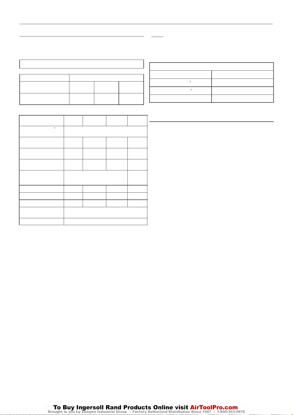
ENGINEERING DATA
Compressor
Maximum operating
pressure psig (bar)
Factory set reload
pressure psig (bar)
Model
Pressure Dew Point ( F)
(see note 3. below)
Base–Mounted Dryer
Package Weight (lb)
120 Gallon Tank Dryer
Package Weight (lb)
240 Gallon Tank Dryer
Package Weight (lb)
Electrical Supply
(+/– 10%) (AC)
(see note 2. below)
L.R.A. Current (Amps)
F.L.A. Current (Amps)
Total Installed Power (kW)
Electrical Protection Class
(Std.)
Refrigerant Type
125
(8.62)
110
(7.58)
1367
1691
1960
45.0
9.6
0.96 1.19 1.19
UP6 15 - 30
150
(10.34)
135
(9.31)
UP6 20
1411
1735 1775 1861
2004 2044 2130
115V / 1ph / 60Hz
45.0 48.8 48.8
9.6 12.3 12.3
0.96
NEMA 1 (IP20)
UP6 25
38
1451
134a
200
(13.79)
185
(12.76)
UP6 30UP6 15
1537
Notes:
1. Electrical data refers to dryer only.
2. The dryer requires a separate power supply from the compressor
drive.
3. Rated at:
Working Pressure (psig)
Inlet Air Temperature ( F)
Ambient Temperature ( F)
Relative Humidity (%)
100
100
100
100
Notes on the use of the Schrader non–return valve.
ATTENTION
1. This unit is equipped with refrigerant as for quantity and kind clearly
shown in operating manual and with identification label.
2. Any ordinary test and / or refrigerant recharge by means of
connections can take place only after refrigerant evacuation. The
evacuation must be proportional to dimensions and length of the
connections used. The use of the valve can be justified only when the
dryer is not in working order.
3. During the unit guarantee period, the Schrader valve can be used by
authorized staff only, otherwise any damage caused by a wrong
refrigerant recharge will invalidate warranty.
Page 42
40
UP6 15, UP6 20, UP6 25, UP6 30
http:/air.ingersollrand.com
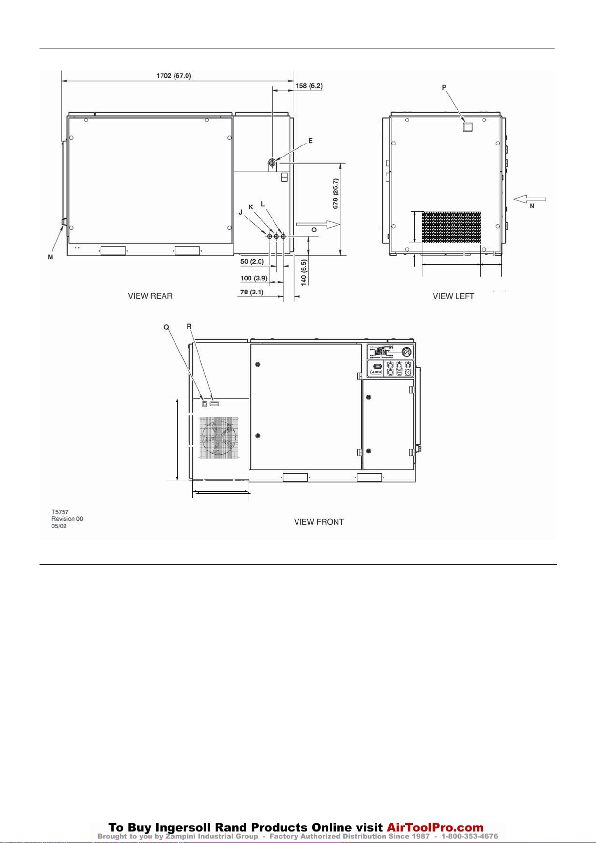
BASE MOUNTED UNITS
DRYER OPTION
317.3 (12.5)
596.3 (23.5)
49
165
600
413.5
KEY
A Pre filter
B Compressor and cooling air intake
C Starter box
D Cooling air exhaust
E 1.00” BSPT air discharge
E 1.00” NPT air discharge
F Customer power inlet
G Fork lift openings
Fork lift hole covers must be installed after unit is in place to
reduce noise and ensure proper cooling of package)
H Button, emergency stop
I Primary compressor service door
J 0.25 inch BSPT moisture separator drain
K 0.25 inch BSPT dryer drain
L 0.25 inch BSPT air filter drain
M 1.00 inch NPT plug
N Dryer air inlet
O Dryer air exhaust
P Filter restriction indicator
Q Dryer On/Off switch
R Dew point indicator
Page 43
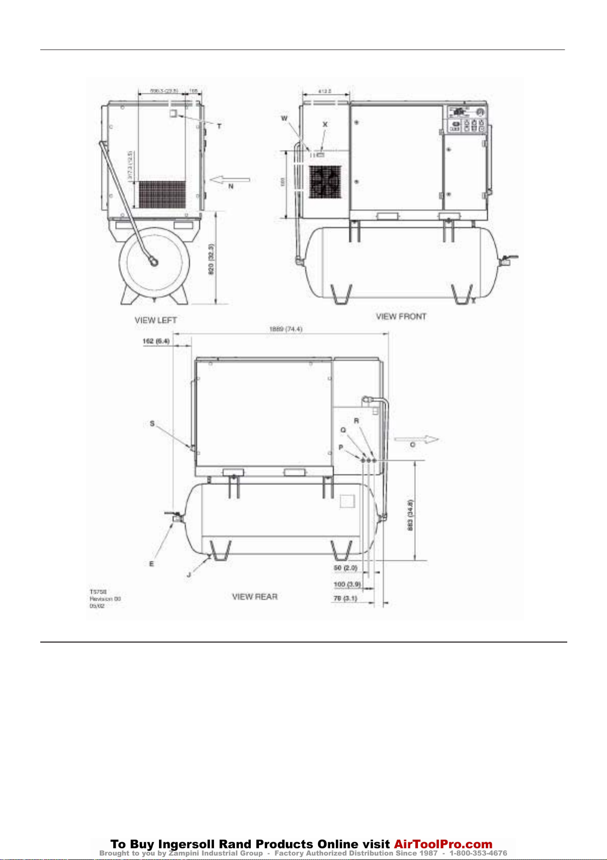
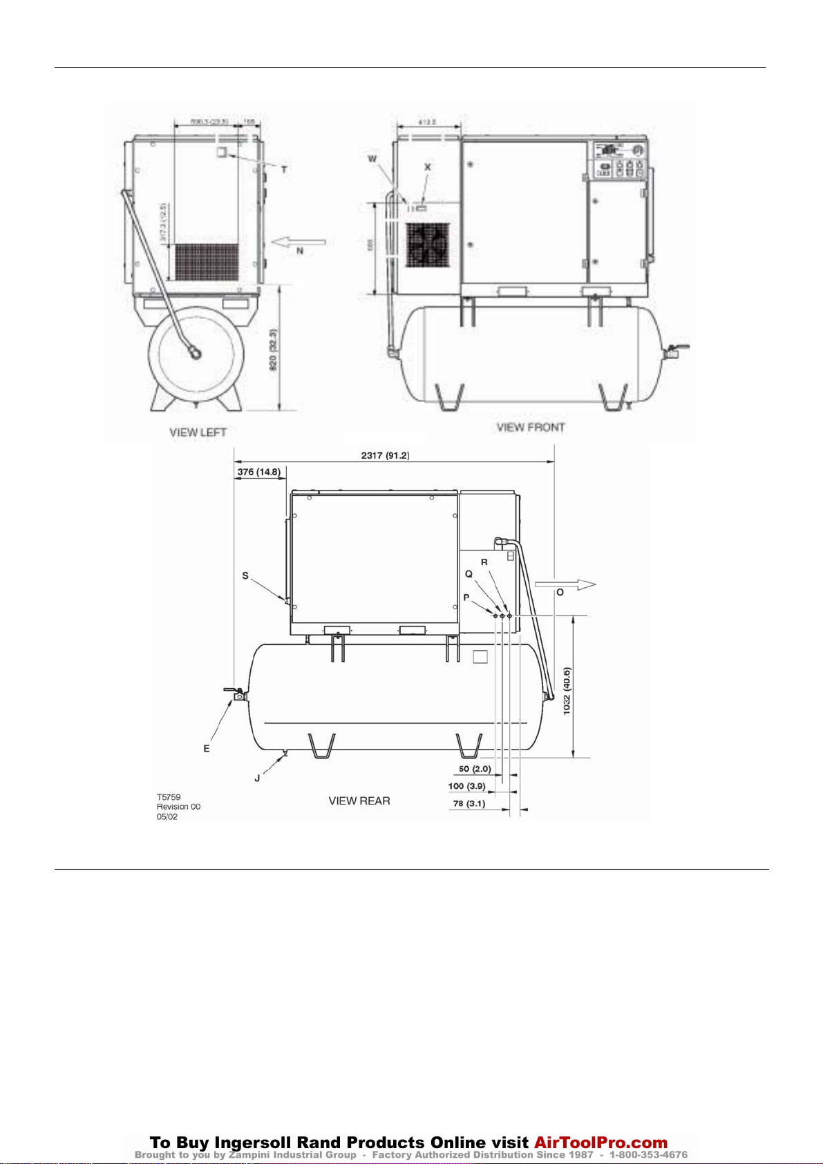
TANK MOUNTED (120 GALLON)
http:/air.ingersollrand.com
UP6 15, UP6 20, UP6 25, UP6 30
60 Hz UNITS
DRYER OPTION
41
KEY
A Pre filter
B Compressor and cooling air intake
C Starter box
D Cooling air exhaust
E 1.00” BSPT air discharge
F Customer power inlet
G Fork lift openings
H Air receiver (120 gallons)
I Automatic drain valve
J Valve, drain
K Button, emergency stop
L Primary compressor service door
M Inspection port
N Dryer air inlet
O Dryer air exhaust
P 0.25 inch BSPT moisture separator drain
Q 0.25 inch BSPT dryer drain
R 0.25 inch BSPT air filter drain
S 1.00 inch NPT plug
T Filter restriction indicator
W Dryer On/Off switch
X Dew point indicator
Page 44
42
UP6 15, UP6 20, UP6 25, UP6 30
http:/air.ingersollrand.com
TANK MOUNTED (240 GALLON)
60 Hz UNITS
DRYER OPTION
KEY
A Pre filter
B Compressor and cooling air intake
C Starter box
D Cooling air exhaust
E1.00” BSPT airdischarge
F Customer power inlet
G Fork lift openings
HAir receiver (240 gallons)
I Automaticdrainvalve
J Valve, drain
K Button, emergency stop
LPrimary compressor service door
M Inspection port
N Dryer air inlet
O Dryer air exhaust
P0.25 inch BSPT moisture separator drain
Q0.25 inch BSPT dryer drain
R0.25 inch BSPT airfilter drain
S1.00 inch NPT plug
TFilter restriction indicato
W Dryer On/Off switch
XDewpoint indicator
r
Page 45
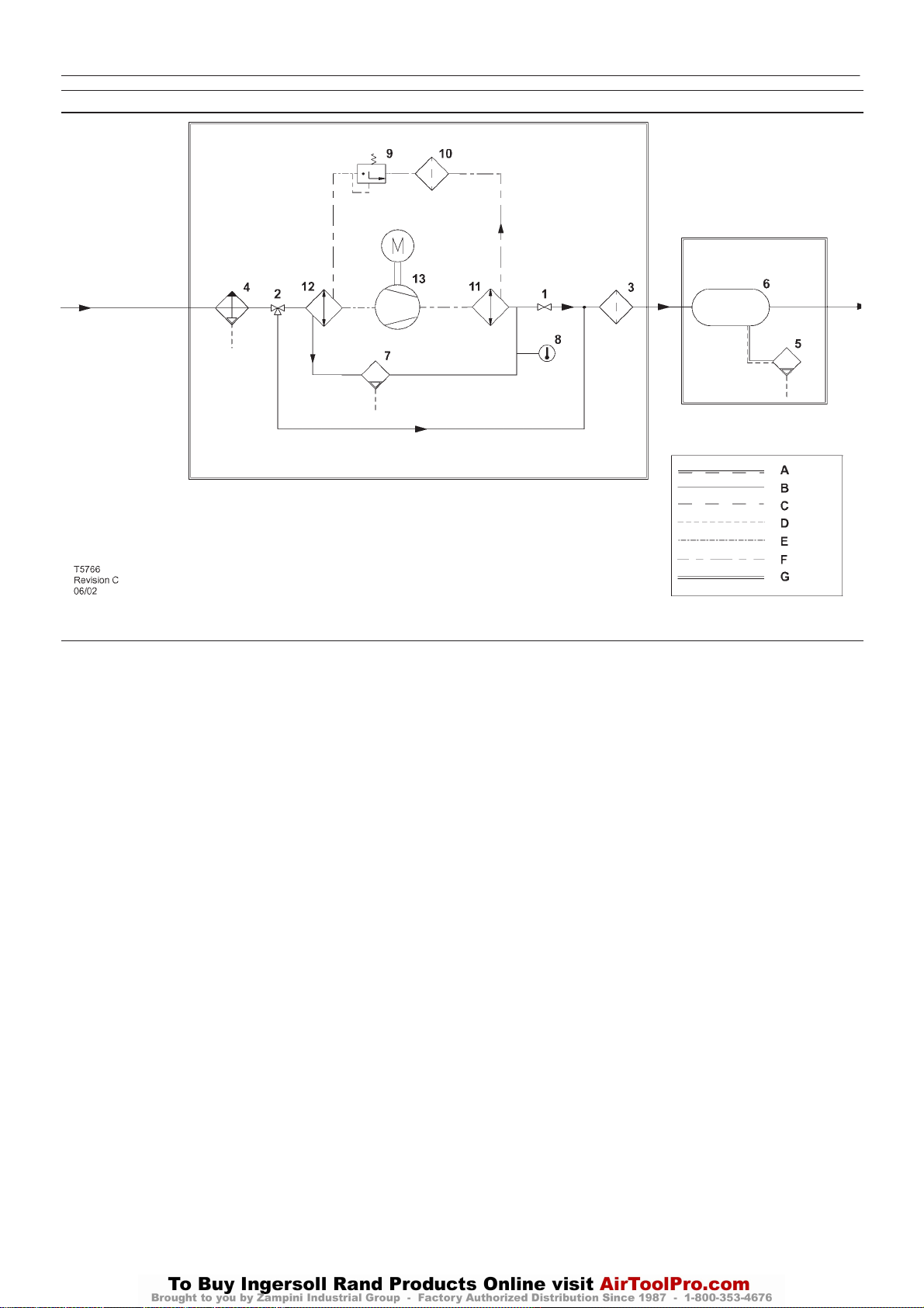
ELECTRO – PNEUMATIC CONTROL AND INSTRUMENTATION DIAGRAM
http:/air.ingersollrand.com
UP6 15, UP6 20, UP6 25, UP6 30
DRYER OPTION
43
KEY
1 Valve, isolation
2 Valve, three way bypass
3. Filter, air
4Moisture separator
5. Valve, autodrain
6 Receiver, air
7. Valve, drain
8. Indicator, dew point colour
9 Valve, expansion
10 Filter, refrigerant
11. Condenser
12 Evaporator
13 Refrigerant compressor
AAir/Coolant
BAir
C Coolant
D Condensate
E Component boundary
F Refrigerant
G Option
Page 46
44
UP6 15, UP6 20, UP6 25, UP6 30
http:/air.ingersollrand.com
DRYER OPTION
27
43
27
42
41
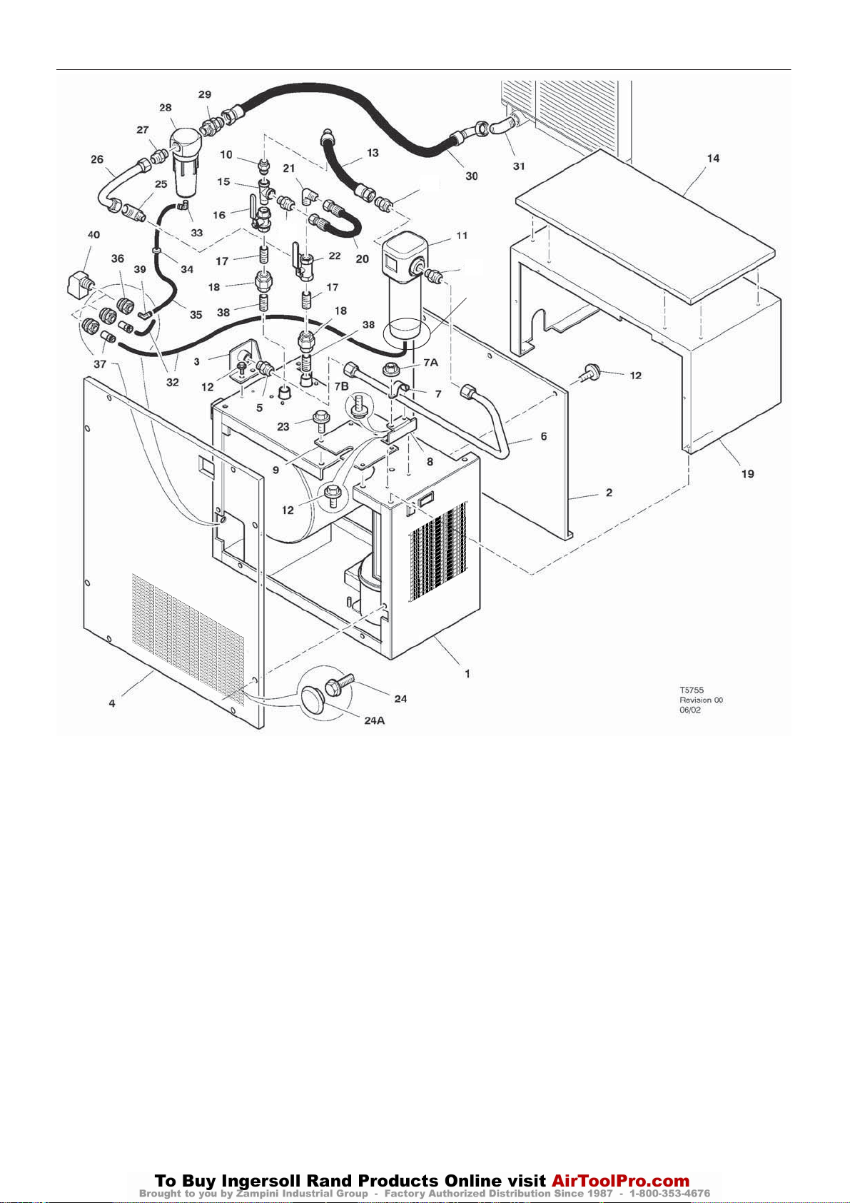
Item ccn Qty. Description Item ccn Qty. Description
1 23320955 1 Dryer
60Hz – 15-20HP
23335631 1 Dryer
60Hz – 25-30 HP
2 22067292 1 Panel
3 22100648 1 Bracket
60Hz
4 23321920 1 Panel
5 95937520 1 Connector
60HZ
6 22100549 1 Tube assembly
7 22070304 1 Bracket
7A 96737564 2 Nut
7B 96705058 2 Setscrew
8 22100556 1 Bracket
9 22097968 1 Panel
10 95937538 4 Connector
11 85565182 1 Filter, air
12 92368687 14 Setscrew
13 85560985 1 Hose assembly
14 22099295 1 Panel
15 95954269 1 Tee
16 22098750 1 Valve, ball
17 95953576 2 Nipple
18 95996153 2 Connector
Page 47
43
http:/air.ingersollrand.com
UP6 15, UP6 20, UP6 25, UP6 30
27
27
42
41
DRYER OPTION
45
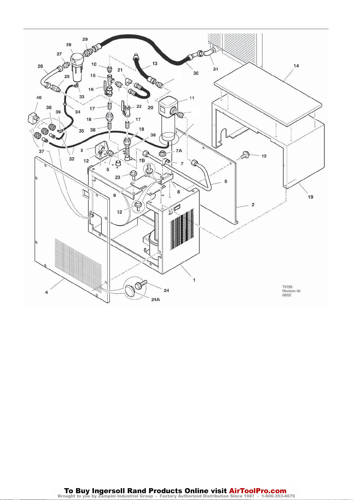
Item ccn Qty. Description Item ccn Qty. Description
19 22097869 1 Cover
20 85560275 Hose assembly
21 95937637 1 Elbow
22 22097588 1 Valve, ball
23 96742689 6 Setscrew
24 96742689 AR Screw
24A 96742689 AR Plug
25 95937652 1 Elbow
26 22070825 1 Tube assembly
27 95937520 3 Connector
28 22101083 1 Separator, water
29 22098859 1 Connector
1
30 85561215 1 Hose assembly
31 95937645 1 Elbow
32 22101414 AR Tube (Nylon)
33 39155577 1 Elbow
34 85583367 1 Grommet
35 39124813 AR Tube (Nylon)
36 54514583 3 Fitting
37 22132971 2 Adaptor
38 95928040 2 Nipple
39 39155478 1 Elbow
40 37143542 3 Elbow
Page 48
46
UP6 15, UP6 20, UP6 25, UP6 30
http:/air.ingersollrand.com
DRYER OPTION
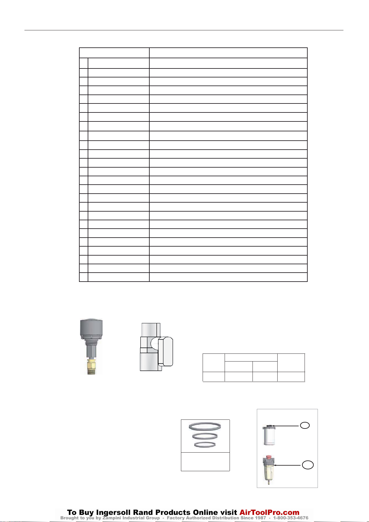
ADDITIONAL SPARE PARTS FOR DRYER OPTION
CCN
38457636 SCREEN, DRAIN
38457461
*
*
*
*
*
*
*
*
*
*
*
*
*
38461364 COMPRESSOR, REFRIGERANT 115V - 25/30HP (18/22KW)
38460150 COMPRESSOR, REFRIGERANT 230V - 15/20HP (11/15KW)
38461489 COMPRESSOR, REFRIGERANT 230V - 25/30HP (18/22KW)
38461471 FAN MOTOR - 16W, 115V
38461497 FAN MOTOR - 16W, 230V
38461463 FAN MOTOR - 34W, 115V
38461505 FAN MOTOR - 34W, 230V
38461372 FAN BLADE
38459665 DRAIN SOLENOID VALVE - 115V
38457537 DRAIN SOLENOID VALVE - 230V
38459723 RELAY
38461380 THERMOMETER
38461398 FAN PRESSURE SWITCH
38461406 HIGH PRESSURE SWITCH
38461414 TIMER
38457826 ON/OFF SWITCH
38457602 DEHYDRATING FILTER
38461422 FILLING GAS VALVE
38461430 HEAT EXCHANGER - 15/20HP (11/15KW)
38461448 HEAT EXCHANGER - 25/30HP (18/22KW)
38459186 CONDENSER - 15/20HP (11/15KW)
38461455 CONDENSER - 25/30HP (18/22KW)
38461356
COMPRESSOR, REFRIGERANT 115V - 15/20HP (11/15KW)
BY-PASS VALVE
DESCRIPTION
* Must have EPA certified technician to order.
AUTOMATIC DRAIN
85566404
MANUAL DRAIN
85566412
Model Filter
85566446
BSPT NPT
85564664
85565182 85565703
Element
Page 49
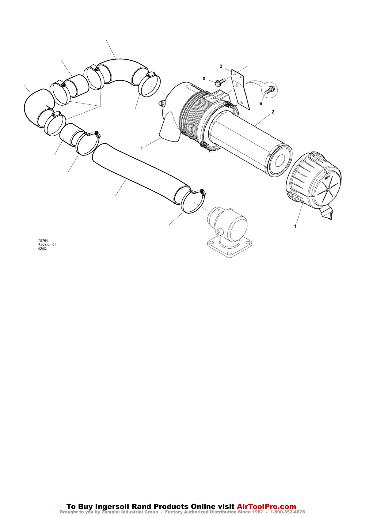
HIGH DUST FILTER OPTION
http:/air.ingersollrand.com
UP6 15, UP6 20, UP6 25, UP6 30
5
8
5
4
4
8
10
7
47
10
Item ccn Qty. Description Item ccn Qty. Description
1 36897999 1 Filter
2 35393685 1 Element, air filter
3 22245534 1 Bracket
4 95340683 4 Clamp
5 89295935 2 Hose
6 96712153 2 Screw
7 22155345 1 Hose
8 22153647 2 Pipe
9 92368687 2 Screw
0
23411135 2 Clamp, Bridge
1
Page 50
48
UP6 15, UP6 20, UP6 25, UP6 30
http:/air.ingersollrand.com
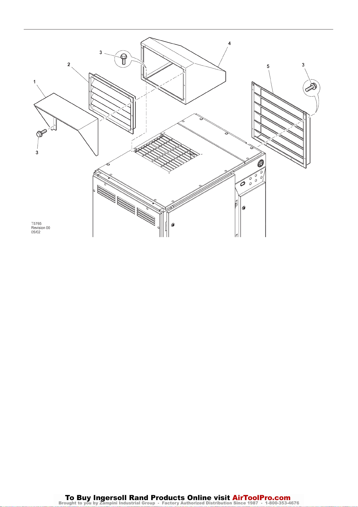
OUT DOOR MODULE OPTION
Item ccn Qty. Description Item ccn Qty. Description
1 22134597 1 Cover
2 22127500 1 Louvre
3 92368687 AR Screw
4 22127328 1 Box
5 22053730 1 Louvre
Page 51

PORO OPTION – ELECTRO–PNEUMATIC 49
http:/air.ingersollrand.com
UP6 15, UP6 20, UP6 25, UP6 30
POWER OUTAGE RESTART OPTION
For customers that have interruptions in their incoming power supply
to the compressor and must maintain an uninterrupted supply of
compressed air, the Power Outage Restart Option allows a
compressor to restart automatically 10 seconds (adjustable) after
incoming power is restored.
FUNCTION TEST
To test the operation of the Power Outage Restart Option:
1. Slowly open the main isolation valve.
2. Start the compressor.
3 The compressor will load automatically if there is sufficient demand
for air. Allow the compressor to load.
4. Open the main disconnect to remove power from the compressor.
5. Close the main disconnect to reapply power to the compressor. The
horn will sound for ten seconds; then the compressor will start
automatically.
Page 52
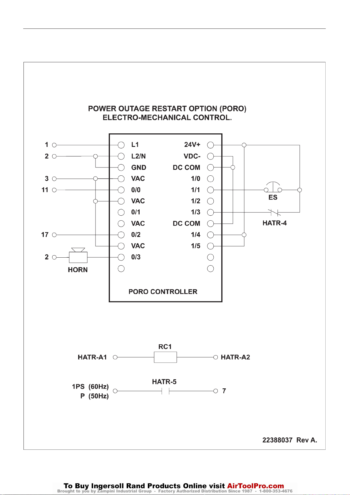
50
UP6 15, UP6 20, UP6 25, UP6 30
http:/air.ingersollrand.com
PORO OPTION – ELECTRO–PNEUMATIC
Page 53
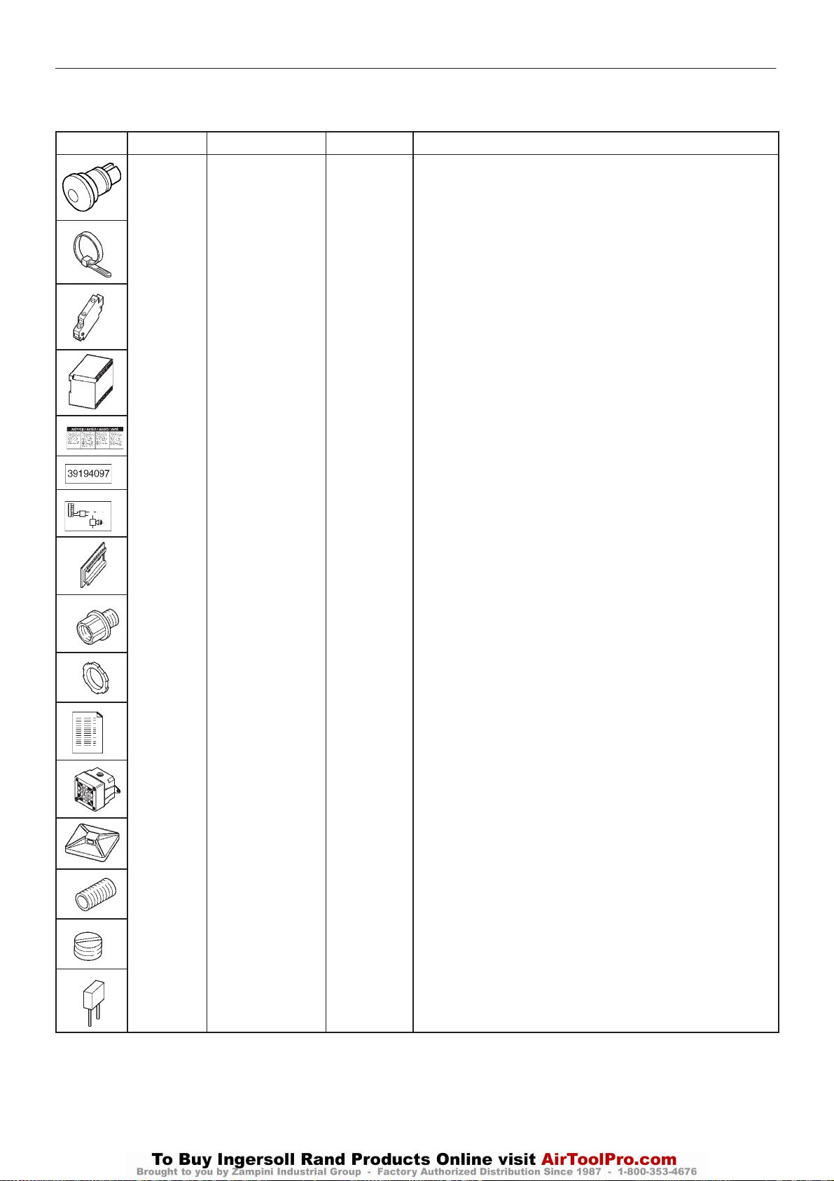
PORO OPTION – ELECTRO–PNEUMATIC 51
http:/air.ingersollrand.com
UP6 15, UP6 20, UP6 25, UP6 30
PARTS LIST FOR POWER OUTAGE RESTART OPTION
(P/N 22396600)
ITEM PART NUMBER QUANTITY DESCRIPTION
1 1
2 35266788 8 Tie, cable
3 22265946 1 Contact, auxilliary
4 22396592 1 Controller, LOGIC PORO
5 22140545 1 Decal: PORO
6 39194097 1 Decal: Power Out Restart Option
7 22388037 1 Decal: Schematic
8 39331954 1 DIN rail
22113344 Button, emergency stop
9 35275494 1 Hub
10 39108949 2 Locknut
11 22396618 1 Instructions
12 39100136 1 Horn, Weather Resistant
13 39133467 8 Mount
14 95785192 1 Nipple
15 39146733 1 Plug
16 39203443 1 Suppressor
Page 54
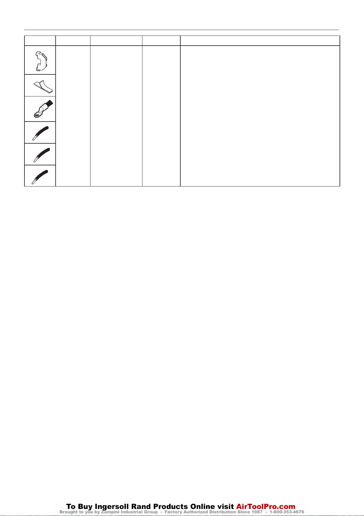
52
UP6 15, UP6 20, UP6 25, UP6 30
http:/air.ingersollrand.com
PORO OPTION – ELECTRO–PNEUMATIC
ITEM PART NUMBER QUANTITY DESCRIPTION
17 39252937 2 Block, end stop
18 39309554 1 Tape, adhesive
19 35246131 1 Terminal
20 39204763 1.2m (4ft) Wire, Blue 16 Ga
21 39129085 1.2m (4ft) Wire, Red 16 Ga
22 39146790 1.2m (4ft) Wire, Green 16 Ga
Page 55

PORO OPTION – INTELLISYS
http:/air.ingersollrand.com
UP6 15, UP6 20, UP6 25, UP6 30
53
OPERATION
POWER OUTAGE RESTART OPTION
For customers that have interruptions in their incoming power supply
to the compressor and must maintainanuninterrupted supply of
compressed air, the Power Outage Restart Option allows an Intellisys
compressor to restart automatically 10–120 seconds (adjustable) after
incoming power is restored.
The Power Outage Restart Option is turned on by using the customer
set routine on the Intellisys
isadjustable from 10–120 seconds, can also be adjusted while inthe
set routine on the Intellisys controller. Any time power is restored to
the compressor after a power interruption and if the compressor was
running when power was lost, a horn located on the side of the starter
box will sound during the restart time delay (10–120 seconds), after
which the compressor will automatically start. After starting, the
compressor will return to the mode of operation that the compressor
was inprior to the power interruption.
To operate in the power outage restart mode, proceed with
following steps:
1. Power up the unit and wait for the Intellisys display to read READY
TO START.
2. Press the SET button once to enter the customer set point
routine. The Set Offline Air Pressure indicator will light and the
display will show the set point pressure.
3. Press and release the SET button multiple times until the message
PWROUTRSTROFFisdisplayed.
4. Push the up or down arrows to change to the desired condition. ON
inthedisplay indicates Power Outage Restart is turned on and OFF in
the display indicates Power Outage Restart is turned off.
5. Once the selection has been made, press SET button to put the
selection into Intellisys memory. The display will flash twice and the
message will change to STR DELAY 10 Sec iftheoption was turned
on. This message will only display if the Power Outage Restart Option
is turned on.
6. Use the up or down arrows to select the desired delay time (10–120
sec.).
7. Press SET and the display will flash twice indicatingthe change has
been made.
8. Push the DISPLAY SELECT BUTTON or wait 30 seconds for the
controller to automatically exit the set routine. The display returns to
READY TO START.
controller. The restart time delay, which
Function test
To test the operation of the Power Outage Restart Option:
1. Slowly open the main isolation valve.
2. Push the green START button on the Intellisys
compressor.
3. The compressor will load automatically if there is a sufficient
demand for air. Allow the compressor to load.
4. Open the maindisconnect to remove power from the compressor.
5. Close the maindisconnect to reapply power to the compressor.The
horn will sound and the Intellisys
___SEC.The display will count down the time until the compressor
starts automatically and the horn stops. After starting, the compressor
will automatically return to the same mode of operation as prior to the
power interruption.
Fault Analysis
1. If the Intellisys display indicates the count down message and the
horn does not sound, check the wiring of the horn.
2. If the Intellisys
the horn does not sound and the unit does not restart automatically,
verify that the Option has been turned on.
display does not indicate the count down message,
display will read START IN
display to start the
Page 56
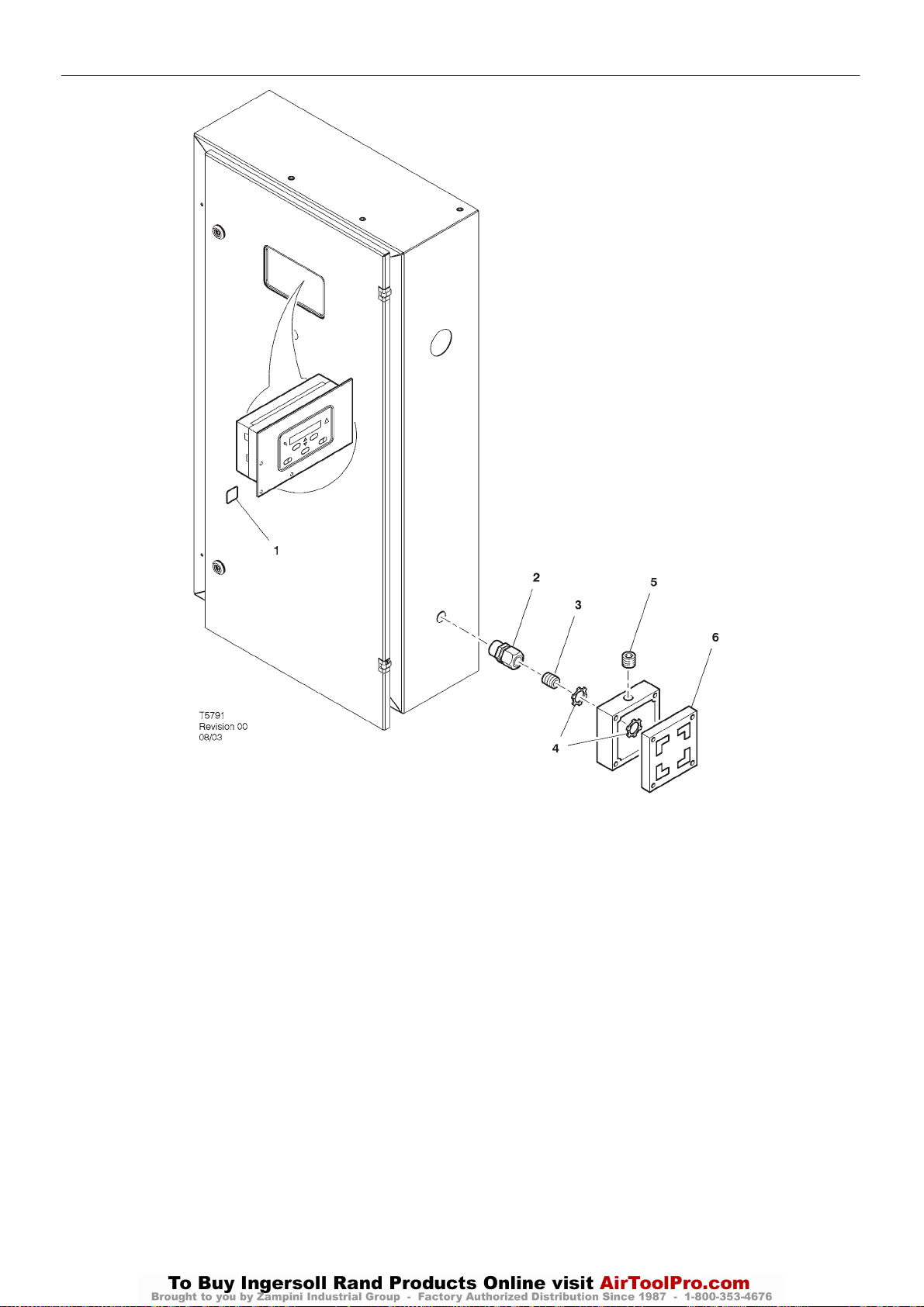
54
UP6 15, UP6 20, UP6 25, UP6 30
http:/air.ingersollrand.com
PORO OPTION – INTELLISYS
Item ccn Qty. Description Item ccn Qty. Description
1 39194097 1 Option, Module
2 35275494 1 Connector, bulkhead
3 95934279 1 Nipple
4 39108949 2 Locknut
5 39146733 1 Plug
6 39100136 1 Horn
Page 57
UP6 15, UP6 20, UP6 25, UP6 30
MANUAL DE OPCIONES
Opción Intellisys
Opción de secador
Opción para alta cantidad de polvo
Opción de módulo al aire libre
Opción PORO
60Hz
Este manual contiene
importante información sobre
seguridad y ha de ponerse a
disposición del personal
encargado del
funcionamiento y
mantenimiento de la
máquina.
C.C.N. : 80445174 es
REV : B
FECHA : ENERO 2009
Page 58

Page 59

CONTENIDO & ABREVIATURAS
http:/air.ingersollrand.com
UP6 15, UP6 20, UP6 25, UP6 30
1
CONTENIDO
1 CONTENIDO
2 PREAMBULO
3 CALCOMANIAS
6 SEGURIDAD
8 OPCION INTELLISYS
31 OPCION DE SECADOR
47 OPCION DE FILTRO DE ALTA CANTIDAD DE
POLVO
48 OPCION DE MODULO AL AIRE LIBRE
49 OPCIÓN PORO – ELECTRONEUMÁTICA
53 OPCIÓN PORO – INTELLISYS
ABREVIATURAS Y SIMBOLOS
#### Para el número de derie, sirvanse contactar
con Ingersoll Rand
–>#### Hasta serie nº
####–> Desde serie nº
* No dibujado
{ Opcion
NR No necesario
AR Según se necesite
SM Sitemaster/Sitepack
HA Máquina para ambiente severo
WC Máquina refrigerada por agua
AC Máquina refrigerada por aire
ERS Sistema de recuperación de energía
T.E.F.C. Motor totalmente blindado refrigerado por
aire (IP55)
O.D.P. (motor) Abierto a prueba de goteo
Page 60
2
UP6 15, UP6 20, UP6 25, UP6 30
http:/air.ingersollrand.com
PREAMBULO
Este manual se provee para cubrir las instrucciones y datos
técnicos para opciones adicionales a la gama de compresores
estándar UP. Se facilita como COMPLEMENTO de los manuales
estándares de operadores y de piezas y NUNCA deberán
emplearse para el funcionamiento de la máquina completa.
El contenido de este manual es propiedad y material confidencial
de Ingersoll Rand y no puede reproducirse sin el consentimiento
previo por escrito de Ingersoll Rand.
Ninguna parte de lo contenido en este documento puede
entenderse como promesa, garantía o representación, implícita o
explícita, respecto a los productos Ingersoll Rand que en él se
describen. Tales garantías u otros términos y condiciones de venta de
los productos deberán estar deacuerdo con los términos y condiciones
estándar de venta para tales productos, que están a disposición de los
clientes si lo solicitan.
Este manual contiene instrucciones y datos técnicos para todas las
operaciones de empleo normales y de mantenimiento rutinario. Las
reparaciones mayores no están comprendidas en este manual y
deben encomendarse o consultarse a un concesionario de servicio
autorizado Ingersoll Rand.
Todos los componentes, accesorios, tuberías y conectores
incorporados al sistema de aire comprimido, deberán ser:
. de buena calidad, adquiridos a un fabricante de buena reputación
y, en lo posible, de un tipo aprobado por Ingersoll Rand
. claramente de un régimen adecuado para una presión igual, como
mínimo, a la máxima presión de trabajo premisible de la máquina
compatibles con el lubricante/ refrigerante del compresor
. acompañados de instrucciones para que su instalación,
funcionamiento y mantenimiento se lleven a cabo con seguridad.
Los departamentos de Servicio de Ingersoll Rand puede facilitar
detalles de los equipos aprobados.
Esta máquina se ha concebido y suministrado para su utilización
únicamente bajo las condiciones y en las aplicaciones especificadas
a continuación:
. Compresión de aire de ambiente normal sin gases, vapores o
partículas adicionales conocidos o detectables.
. Funcionamiento dentro de la gama de temperatura ambiente
especificada en la sección INFORMACION GENERAL de este
manual.
Uso de la máquina en cualquiera de las siguientes
situaciones:–
a) No esta aprobado por Ingersoll Rand.
b) Puede perjudicar la seguridad de los usuarios y otras
personas, y
c) Puede perjudicar cualquier reclamacion hacha contra
Ingersoll Rand.
TABLA 1
Uso de la máquina para producir aire comprimido para:
a) consumo humano directo
b) consumo humano indirecto, sin el correspondiente filtrado y
purificado.
Uso de la máquina fuera del rango de temperatura ambiente
especificado en la sección de INFORMACION GENERAL de este
manual.
Uso de la máquina donde haya riesgo real o potencial de niveles
peligrosos de gases o vapores inflamables.
ESTA MÁQUINA NI SE HA DESTINADO NI DEBE UTILIZARSE
EN AMBIENTES POTENCIALMENTE EXPLOSIVOS, INCLUIDAS
LAS SITUACIONES EN LAS QUE SE HALLEN PRESENTAS
GASES O VAPORES INFLAMABLES.
Uso de la máquina con componentes no aprobados por
Ingersoll Rand.
El empleo de piezas para reparaciones no genuinas y distintas a las
incluidas en las listas de piezas aprobadas por Ingersoll Rand, puede
originar condiciones de riesgo sobre las que Ingersoll Rand no tiene
control alguno. Por consiguiente, Ingersoll Rand declina toda
responsabilidad acerca de equipos en los que no se instalen piezas
aprobadas. Pueden verse afectadas las condiciones generales de
garantía.
Ingersoll Rand se reserva el derecho a realizar cambios y mejoras
de los productos sin previo aviso y sin incurrir en ningún tipo de
obligación a realizar tales cambios o añadir tales mejoras en aquellos
productos que se hayan vendido previamente.
Los usos para lo que esta diseñada esta máquina estan
subrayados abajo y también se dan algunos ejemplos de uso
incorrecto, sin embargo Ingersoll Rand no se ouede anticipar a cada
aplicación o situación de trabajo que pueda ocurrir.
SI TIENE DUDAS CONSULTE AL SUPERVISOR.
Uso de la máquina con componentes de seguridad o de control
perdidos o averiados.
La compañia no acepta resposabilidades por arrores en la
traducción de la versión original en Inglés.
INTELLISYS es marca registrada de Ingersoll Rand Company
USA.
¤ COPYRIGHT 2008
INGERSOLL RAND
Page 61
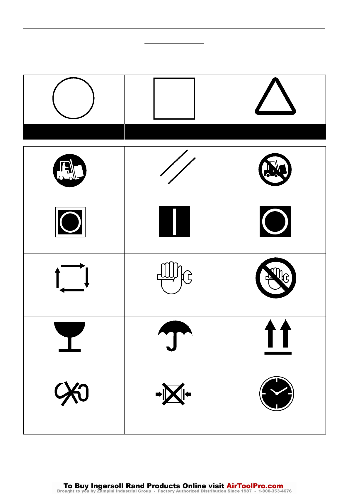
CALCOMANIAS 3
http:/air.ingersollrand.com
UP6 15, UP6 20, UP6 25, UP6 30
SIMBOLOS ISO
FORMA GRAFICA Y SIGNIFICADO DE LOS SIMBOLOS ISO
Prohibición/Obligatoriedad Información/Instrucciones Advertencia
Utilizar la carretilla elevadora en esta lado. REPOSICIONAR No utilizar la carretilla elevadora en esta lado.
Parada de emergencia. Encendido (energia) Apagado (energia).
REARRANQUE AUTOMATICO MANTENIMIENTO MANUTENZIONE PROIBITA
FRAGIL MANTENER SECO COLOCAR EN ESTA POSICION
NO USAR GANCHOS
NO USAR MORDAZAS DE AGARRE
LATERAL
HORAS
Page 62
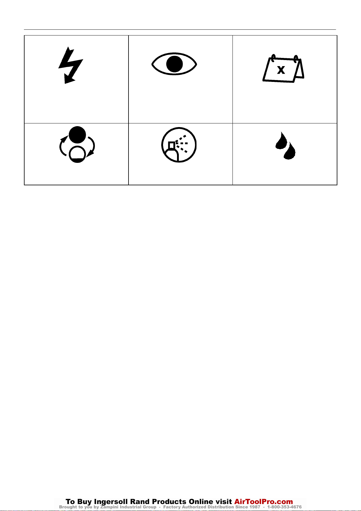
CALCOMANIAS4
UP6 15, UP6 20, UP6 25, UP6 30
http:/air.ingersollrand.com
ENERGIA ELECTRICA INSPECCIONAR
CAMBIAR / MONTAR DE NUEVO LIMPIAR.
Cada X meses, si lo requieren más pronto por
las horas de funcionamiento
HUMEDAD
Page 63
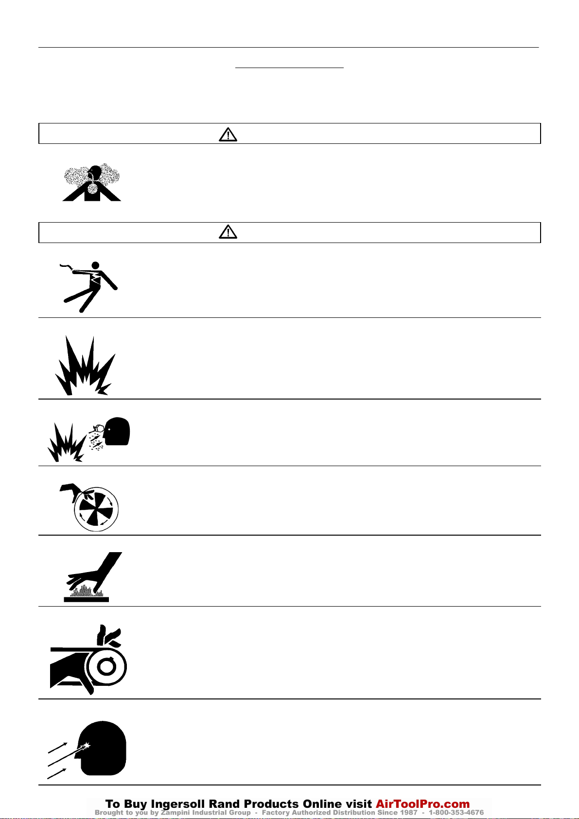
CALCOMANIAS 5
http:/air.ingersollrand.com
UP6 15, UP6 20, UP6 25, UP6 30
SIMBOLOS ANSI
FORMA GRAFICA Y SIGNIFICADO DE LOS SIMBOLOS ANSI
PELIGRO
AIRE DE ADMISION. Puede contener de carbono y otros contaminantes que pueden ocasionar graves lesiones e
incluso la muerte. No respirar este aire. Los compresores de aire de Ingersoll Rand no se han concebido, destinado
o aprobado para aire respirable. El aire comprimido no deberá utilizarse para aplicaciones de aire respirable a menos
que sea tratado de conformidad con todos los códigos y normas correspondientes.
.
ADVERTENCIA
TENSION PELIGROSA. Puede ocasionar graves lesiones e incluso la muerte. Desconectar la corriente y purgar la
presión del tanque antes de realizar el servicio. Bloquear/etiquetar la máquina. El compresor ha de estar conectado a
un circuito puesto debidamente a tierra. Véanse las instrucciones de puesta a tierra indicadas en el manual. No
operar el compresor en condiciones de humedad. Almacenarlo bajo techo.
RIESGO DE INCENDIO O EXPLOSION. La formación de arco desde componentes del compresor puede encender
líquidos y vapores inflamables que pueden dar lugar a graves lesiones. Nunca deberá operarse el compresor cerca
de líquidos o vapores inflamables. Si se usa para pulverizar materiales inflamables, mantenga el compresor a 18
metros, como mínimo, de la zona donde se efectúe la pulverización.
ALTA PRESION DEL AIRE. Los tanques afectados por herrumbre pueden ocasionar explosión y graves lesiones o la
muerte. Colector bajo presión. El operador deberá eliminar la presión del depósito antes de realizar trabajo de
mantenimiento alguno. Además del vaciado automático, opere semanalmente la válvula de vaciado manual. La
válvula de vaciado manual se encuentra en la parte inferior del depósito.
PIEZAS MOVILES. Pueden ocasionar graves lesiones. No operar con las defensas retiradas. La máquina puede
ponerse en marcha automáticamente. Desconectar la corriente antes de realizar servicio alguno. Bloquear/etiquetar
la máquina.
SUPERFICIES CALIENTES. Pueden ocasionar graves lesiones. No tocarlas. Dejarlas enfriar antes de realizar
servicio alguno. No tocar el compresor ni conductos cuando estén calientes.
CORREAS Y ROLÑDANAS MOVILES SIN PROTECCION.
Pueden ocasionar graves lesiones e incluso la muerte.
No operar sin las defensas en su posición. Desconectar la corriente antes de realizar servicio alguno.
Bloquear/etiquetar la máquina.
El escape del flujo de aire puede contener desechos volantes.
Deberá utilizarse protección de seguridad en todo momento.
Page 64

6
UP6 15, UP6 20, UP6 25, UP6 30
http:/air.ingersollrand.com
SEGURIDAD
¡PELIGRO!
El riesgo OCASIONARA la MUERTE, GRAVES LESIONES o
importantes daños en los bienes si se pasa por alto. Las instrucciones
deberán respetarse con precisión para evitar las lesiones o la muerte.
¡ADVERTENCIA!
El riesgo PUEDE ocasionar la MUERTE, GRAVES LESIONES o
importantes daños en los bienes si se pasa por alto. Las instrucciones
deberán respetarse con precisión para evitar las lesiones o la muerte.
PRECAUCIONES
Las precauciones llaman la atención sobre las instrucciones que
deben seguirse estrictamente para evitar daños en el equipo, el
proceso o sus alrededores.
AVISOS
Los avisos se utilizan para dar información suplementaria.
PRECAUCION DE AIRE RESPIRABLE
Los compresores de aire Ingersoll Rand no han sido concebidos,
destinados o aprobados para aire respirable. El aire comprimido no
deberá utilizarse para aplicaciones de aire respirable, a menos que sea
tratado de conformidad con todos los códigos y reglamentos
aplicables.
Información general
Asegúrese de que el operador lea y entienda las pegatinas y
consulte el manual antes de realizar mantenimiento u operación de la
unidad.
Asegúrese de que el Manual de Funcionamiento y Mantenimiento
no se retire permanentemente de la máquina.
Asegúerese que el personal de mantenimiento esta entrenado
convenientemente y que han leído los Manuales de Mantenimiento.
No apuntar con boquillas de aire o pulverizadores a persona
alguna.
El aire comprimido y la energía eléctrica pueden ser peligrosos.
Antes de comenzar cualquier trabajo sobre el compresor, asegurar
que la alimentación eléctrica ha sido cortada y que el compresor ha
sido despresurizado.
Utilice protección para los ojos cuando funcione el compresor o
realice trabajos de mantenimiento en el mismo.
Todas las personas situadas cerca de maquinaria en
funcionamiento deberán llevar protección para los oídos y recibir
instrucciones sobre su modo de empleo de conformidad con la
legislación sobre seguridad en el lugar de trabajo.
Asegúrese de que todas las cubiertas protectoras estén en su lugar
y que la capota o las puertas estén cerradas durante la operación.
Las especificaciones de esta máquina son tales que no es
adecuada para usarla en áreas donde exista riesgo de gas inflamable.
La instalación de este compresor debe estar de acuerdo con
códigos eléctricos reconocidos y con cualquier código local de
Seguridad e Higiene.
El empleo de recipientes de plástico en filtros de conductos puede
resultar peligroso. Su seguridad puede verse afectada bien sea por
lubricantes sintéticos o por aditivos utilizados en aceites minerales.
Ingersoll Rand recomienda utilizar sólo recipientes de metal en
sistemas sometidos a presión.
Asegúrese que la máquina trabajando a la presión es conocida por
el personal apropiado.
Todo el equipo de presión de aire instelado o conectado a la
máquina tienen que funcionar a presiones de trabajo de seguridad o al
menos a la presión de tarado de la máquina.
Si se conecta más de un compresor a una planta común aguas
abajo, deberán instalarse y controlarse por procedimientos de trabajo
válvulas de aislamiento eficaces, de forma que una máquina no sea
sometida a presión / sobrepresión accidentalmente por otra.
El aire comprimido no tiene que usarse directamente por ningún
aparato de respiración o máscara.
El aire descargado contiene un porcentaje muy pequeño de aceite
lubricante del compresor y se deberá tener cuidado de que sea
compatible el equipo situado aguas abajo.
Si el aire de descarga se va a liberar en un espacio reducido, debe
proporcionarse una ventilación adecuada.
Cuando se emplee aire comprimido, el personal deberá llevar un
equipo de protección adecuado.
Todas las piezas sometidas a presión, especialmente tubos
flexibles y sus acoplamientos, tienen que ser inspeccionados
regularmente, no tener ningún defecto y han de ser sustituídos de
acuerdo al Manual de instrucciones.
El aire comprimido puede ser peligroso si no se utiliza
correctamente. Antes de realizar ningún tipo de trabajo en la unidad,
asegúrese de que se ha liberado toda la presión del sistema y que la
máquina no puede arrancar accidentalmente.
Evite el contacto de cualquier parte del cuerpo con el aire
comprimido.
Deberá comprobarse periódicamente el funcionamiento de todas
las válvulas de seguridad situadas en el tanque separador.
No someter a presión excesiva al tanque colector o a recipientes
similares superando los límites de diseño.
No usar un tanque colector ni recipientes similares que no cumplan
los requisitos de diseño del compresor. Sírvanse contactar con el
distribuidor si se precisa asistencia.
No taladrar, soldar o alterar de otro modo el tanque colector o
recipientes similares.
Productos
Las siguientes substancias han sido utilizadas en la fabricación de
esta máquina y pueden ser peligrosas para la salud si se utilizan
incorrectamente:–
. grasa conservante
. inhibidor de óxido
. refrigerante
EVITE LA INGESTION, EL CONTACTO CON LA PIEL Y LA
INHALACION DE HUMOS
Transporte
Cuando se transporte o carque una máquina, asegurarse que se
usan los puntos específicos de elevación y de remolque.
Aire comprimido
El aire comprimido puede ser peligroso si no se utiliza
correctamente. Antes de realizar ningún tipo de trabajo en la unidad,
asegúrese de que se ha liberado toda la presión del sistema y que la
máquina no puede arrancar accidentalmente.
ASVERTENCIA
Imponiendo en el compresor una parada normal o de
emergencia sólo desahogará la presión aguas arriba de la válvula
de presión mínima encima del tanque separador.
Si se requiere trabajo de mantenimiento aguas abajo de esta
válvula, cerciorarse de que se desahogue toda la presión en el
punto de ventilación del proceso exterior al compresor.
El equipo de elevación ha de tener capacidad adecuada para el
peso del compresor.
No trabajar ni pasar por debajo del compresor mientras esté
suspendido.
Page 65

Sistema eléctrico
http:/air.ingersollrand.com
UP6 15, UP6 20, UP6 25, UP6 30
Mantener alejados del sistema eléctrico del compresor todas las
partes del cuerpo y las herramientas de mano u otros objetos
conductores. Mantener los pies sobre un suelo seco y estar en pie
sobre superficies aislantes y no entrar en contacto con parte alguna del
compresor cuando se realicen ajustes o reparaciones en partes
expuestas con corriente del sistema eléctrico del compresor.
ADVERTENCIA
Cualquier conexión eléctrica o ajuste sólo deberá ser
realizado por un electricista cualificado competente.
Cerrar y bloquear con lave todas las puertas de acceso cuando el
compresor quede desatendido.
No utilizar extintores destinados a incendios de la Clase A o Clase
B cuando se trate de incendios eléctricos. Utilizar solamente extintores
idóneos para incendios de la clase AB o de la clase ABC.
Efectuar reparaciones únicamente en zonas limpias, secas, bien
iluminadas y ventiladas.
Conectar el compresor únicamente a sistemas eléctricos que sean
compatibles con sus características eléctricas y que sean de su
capacidad nominal.
Eliminación del condensado
Dado que las normas sobre aguas residuales varían entre países
y regiones, el usuario tiene la responsabilidad de establecer los límites
y respetar las normas de su zona en particular. Ingersoll Rand y sus
distribuidores correspondientes se complacerían en asesorar y
ayudar en estos aspectos.
Para más amplia información, consultar la Hoja de Datos de
Materiales 80440043 MSDS, Ultra Coolant English
80440068 MSDS, Ultra Coolant Spanish
80440050 MSDS, Ultra Coolant Portuguese
80442254 MSDS, Xtend Food Grade Coolant English .
SEGURIDAD
7
Page 66
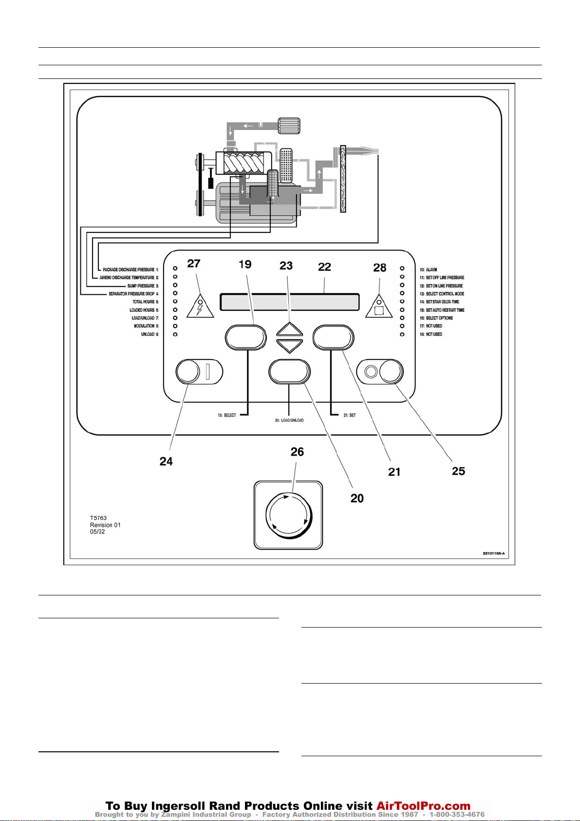
8
UP6 15, UP6 20, UP6 25, UP6 30
http:/air.ingersollrand.com
CONTROL INTELLISYS E INSTRUMENTACION
OPCION INTELLISYS
ANTES DEL ARRANQUE
1. Comprobar el nivel del refrigerante. Restablecerlo, si fuere
necesario.
2. Cerciorarse de que está abierta la válvula principal de descarga.
3. Conectar el aislador eléctrico. Se encenderá el diodo emisor de luz
(LED) de corriente conectada y la pantalla indicará ”Listo para
arrancar”
.
AVISO
Cerciorarse de que todas las tapas de protección están en su
posición
.
ARRANQUE
Pulsar ”Arrancar” (”Start”) [24]. Arrancará el compresor y, acto
seguido, cargará automáticamente.
REARRANQUE POR INTERRUPCIÓN/FALLO DE POTENCIA
(opcional)
Si este valor se fija en ACTIVACION (ON), el compresor arrancará de
nuevo automáticamente cuando se devuelva la corriente al compresor,
si estaba funcionado cuando se interrumpió la corriente.
TIEMPO DE REARRANQUE POR INTERRUPCIÓN/FALLO DE
POTENCIA
Si se fija en ACTIVACION (ON) el valor de arranque de nuevo después
de interrumpir la corriente, éste sería el número de segundos, a partir
de la hora en que se restablezca la corriente, que transcurrirá hasta
que arranque de nuevo el compresor. Durante este tiempo, sonará la
bocina de arranque de nuevo después de una interrupción de la
corriente.
PARADA NORMAL
1. Pulsar ”Parada Descargado” (”Unloaded Stop”) [25]. Descargará
el compresor y, acto seguido, se parará.
2. Desconectar el aislador eléctrico.
Page 67

OPCION INTELLISYS
http:/air.ingersollrand.com
UP6 15, UP6 20, UP6 25, UP6 30
9
PARADA DE EMERGENCIA
1. Pulsar el ”Botón de parada de emergencia [26] y el compresor se
parará de inmediato.
2. Desconectar el aislador eléctrico.
FUNCION DEL PANEL DE INSTRUMENTOS
1 LED DE PRESIÓN DE LA DESCARGA DEL EQUIPO
Éste se iluminará cuando la pantalla indique la presión en la
descarga del equipo.
2 LED DE TEMPERATURA DE DESCARGA DEL AIREND
Este se iluminará cuando la pantalla indique la temperatura de
descarga del airend.
3 LED DE PRESIÓN DEL COLECTOR
Éste se iluminará cuando la pantalla indique la presión del colector.
4 LED DE CAÍDA DE PRESIÓN EN EL SEPARADOR
Éste se iluminará cuando la pantalla indique la caída de presión en
el separador.
5 LED DE HORAS TOTALES
Se iluminará cuando la pantalla indique las horas totales de
funcionamiento del compresor.
6 LED DE HORAS EN CARGA
Se iluminará cuando la pantalla indique las horas totales de
funcionamiento del compresor en carga.
7 LED DE CARGADO / DESCARGADO
Se iluminará cuando el compresor esté funcionando descargado.
8 LED DE MODULACIÓN
Se iluminará cuando el compresor esté funcionando en el modo
modulación. (Nota: La posibilidad de modulación se producirá sólo
cuando el compresor tenga conectado la neumática de regulación
adecuada).
9 LED DESCARGADO
Se iluminará cuando el compresor esté funcionando en el modo
descargado.
10 LED DE ALARMA
Éste parpadeará cuando exista una situación de alarma. La alarma
detectada aparecerá en pantalla y el compresor seguirá funcionando.
La alarma puede ser rearmada pulsando AJUSTE [21].
Se iluminará permanentemente cuando se produzca una situación
de disparo. El compresor parará inmediatamente. La alarma puede ser
rearmada pulsando AJUSTE [21] dos veces en 3 segundos.
OTROS LED
Éstos se iluminarán durante el ajuste de los puntos de consigna
para indicar qué función se está ajustando.
11 DIODO EMISOR DE LUZ (LED) – Fijar presión fuera de línea
12 DIODO EMISOR DE LUZ (LED) – Fijar presión en línea
13 DIODO EMISOR DE LUZ (LED) – Seleccionar modo de control
16 DIODO EMISOR DE LUZ (LED) – Seleccionar opciones
17 DIODO EMISOR DE LUZ (LED) – No se usa
18 DIODO EMISOR DE LUZ (LED) – No se usa
19 PULSADOR DE SELECCION DE INDICACIÓN
Pulsar para avanzar por las condiciones de funcionamiento del
compresor. Se encenderá el correspondiente diodo emisor del luz
(LED) adyacente a la visualización.
Se utiliza para seleccionar diferentes indicaciones de estado
(después de 5 minutos aproximadamente, la pantalla vuelve a indicar
la presión en la descarga del equipo). La actuación sobre este pulsador
en el modo de ”ajuste de puntos de consigna”, provocará el paso a
”Comprobación del equipo” durante dos segundos, luego a ”Preparado
para arrancar”.
20 BOTON DE CARGA/DESCARGA
Este se usa para conmutar manualmente el compresor entre un
modo de control cargado (p.ej.: en/fuera de línea) y funcionamiento sin
carga.
Ver el diodo emisor de luz (LED).
21 PULSADOR DE AJUSTE
Actuando sobre este pulsador, cuando el compresor está parado,
se posibilita el acceso al proceso de ajuste de puntos de consigna. Una
vez en el modo de ajuste de puntos de consigna, actuando sobre este
pulsador se provoca que el controlador pase al punto de consigna
siguiente salvando el valor nuevo del anterior, si éste había sido
modificado.
Actuando sobre este pulsador se consigue el rearme de alarmas
(mientras el compresor está funcionando). El rearme de los disparos
se consigue actuando dos veces en tres segundos sobre este
pulsador (la condición de disparo permanecerá si el defecto indicado
no ha sido corregido).
22 PANTALLA DE CRISTAL LIQUIDO
Indica el estado del compresor, los ajustes de parámetros y los
mensajes de alarma / disparo. Cuando el compresor está funcionando,
la pantalla mostrará normalmente la presión en la descarga del
conjunto.
23 PULSADORES DE FLECHA
Se utilizan para recorrer los mensajes de alarma y disparo. En el
ajuste de puntos de consigna, estos pulsadores se utilizan para
aumentar / disminuir los valores de los puntos de consigna y posibilita
/ imposibilita algunas condi–ciones de operación.
Las llaves de flecha se usan también para seleccionar las bandas
de presión 1(Y) o 2(B) durante la operación normal del compresor.
24 PULSADOR DE ARRANQUE
Cuando se actúa sobre este pulsador se producirá el arranque y la
carga automática del compresor, supuesto que el controlador detecta
una demanda de aire. Cuando se pulsa en el modo ”indicación”; se
producirá el paso a ”Comprobación del equipo” durante 2 segundos,
a continuación a ”preparado para arrancar”.
25 PARADA DESCARGADO
Este pulsador cuando se actúa mientras el compresor está
funcionando, descargará el compresor (si no lo estaba ya) durante 10
segundos y luego lo parará. Ésta es la forma normal de parar el
compresor. Si el compresor ya está parado, ejecutará una
comprobación de LED (todos los Led deberán iluminarse) y mostrará
la revisión del software del controlador.
14 DIODO EMISOR DE LUZ (LED) – Fijar tiempo estrella triángulo
15 DIODO EMISOR DE LUZ (LED) – Fijar tiempo autoarranque
26 PARADA DE EMERGENCIA
Cuando se actúa sobre este pulsador el compresor parará
inmediatamente y mostrará un mensaje de alarma de parada de
emergencia.
Page 68

10
UP6 15, UP6 20, UP6 25, UP6 30
http:/air.ingersollrand.com
OPCION INTELLISYS
27 LED DE PRESENCIA DE TENSIÓN
Éste se iluminará cuando esté presente la alimentación de 8 V al
controlador.
28 LED DE REARRANQUE AUTOMÁTICO
Éste se iluminará cuando el equipo haya parado debido a una baja
demanda de aire. El compresor volverá a arrancar y a cargar
automáticamente en cuanto se reestablezca la demanda de aire.
MENSAJES EN PANTALLA
Cuando el compresor esté funcionando normalmente la pantalla
mostrará la presión de descarga de paquete e iluminará el LED
correspondiente [1]. También aparecerá una flecha en la parte
extrema derecha de la pantalla indicando la banda de presión
seleccionada. Presionando el selector de pantalla [19] cambiará los
valores y el LED correspondiente se iluminará. El controlador regula
todos los aspectos del compresor mientras este está funcionando y
mostrará avisos, o en situaciones graves ejecutará una parada de
emergencia y mostrará una condición de alarma.
MODOS DE CONTRL DE LA MAQUINA
CONTROL DE LA CAPACIDAD
El compresor se ha concebido para trabajar con dos tipos de control
de la capacidad para que resulte adecuado a los requisitos individuales
de la planta. Estos controles son:
A. En línea – Fuera de línea (de serie)
B. En línea – Fuera de línea con modulación en gama superior (extra
opcional)
Uno y otro se hallan disponibles mediante su selección en el panel de
control.
CONTROL EN LINEA – FUERA DE LINEA
Tratándose de aplicaciones que requieran una demanda de aire
ampliamente variada, este modo de control descarga aire a plena
capacidad o a capacidad cero con baja presión del acumulador.
Este modo de funcionamiento es controlado por el transductor
de presión respondiendo a los cambios de la presión del aire de la
planta. Este sensor activa la válvula de solenoide de carga la cual,
a su vez, acciona la válvula de ventilación (purga) y el cierre de la
abertura de ventilación a la atmósfera de la válvula de aspiración
del aire.
El compresor descarga entonces aire a plena capacidad al
sistema de la planta. Si la presión del aire de este sistema se eleva
hasta el punto fijado superior de regulación de la presión, se
desactiva la válvula de solenoide de carga permitiendo que se
cierre la válvula de aspiración. Al mismo tiempo, se abre la válvula
de ventilación permitiendo que descienda la presión del
acumulador.
La regulación de la presión tiene una gama de 0,83 bar (12 psi)
entre sus puntos fijados superior e inferior. El punto fijado superior
se regula a 0,2 bar (3 psi) por encima de la presión nominal de
descarga del compresor.
CONTROL DE MODULACION DE GAMA SUPERIOR (extra
opcional)
Tratándose de plantas que sufran una demanda de aire
relativamente alta y constante, se recomienda el modo de control
de la modulación en la gama superior.
La modulación en la gama superior retiene las características
de control En línea – Fuera de línea, si bien proporciona el equilibrio
del caudal del aire de entrada a medida que se eleva la presión de
la línea hasta el punto fijado de la regulación de la presión fuera de
línea.
Al purgar una pequeña cantidad de la válvula reguladora, lo cual
activa la válvula de solenoide de modular, una reducción de la señal
del aire al cilindro neumático en la válvula de aspiración permite al
cilindro regular la posición de la válvula de aspiración conforme lo
dicte la presión cambiante de la línea.
Si disminuye la demanda de aire hasta un nivel inferior al 70%
de la salida modulada, se incrementará ligeramente la presión de
la línea hasta el límite superior de regulación de la presión,
momento en el que el compresor cambia entonces a la posición de
control fuera de línea y funciona con el acumulador ventilado.
ARRANQUE Y PARADA AUTOMÁTICOS
Para plantas en las que la demanda de aire varíe, cuenten con una
mayor capacidad de almacenamiento de aire, o quieran disponer
automáticamente de capacidad de aire en modo de espera, existe la
opción de Control de arranque y parada.
Durante los períodos de baja demanda, si la presión del conducto
llega al punto de ajuste de la presión de aire fuera de línea del
lntellisys, se activa un cronómetro y se inicia el tiempo de espera. El
tiempo de rearranque automático se ajusta en un intervalo de 2 a 60
minutos. El cronómetro funciona mientras la presión del conducto
permanezca por encima del punto de ajuste en línea del Intellisys. Si
el cronómetro continúa funcionando durante el tiempo de ajuste fijado,
se abrirá un contacto para desactivar las bobinas de arranque del
compresor. Al mismo tiempo, la luz amarilla de rearranque automático
en el panel lntellisys se enciende y aparece el mensaje AUTO
RESTART (rearranque automático) indicando que el compresor se ha
apagado automáticamente y se arrancará automáticamente.
El rearranque automático se produce cuando la presión del
conducto desciende al punto de ajuste en línea del Intellisys.
Para activar el modo de arranque y parada automáticos, seguir los
pasos siguientes:
1. Pulsar el botón SET (ajustar) hasta que aparezca el mensaje AUTO
S/S OFF (a/p automáticos desactivados).
2. Pulsar las flechas arriba o abajo para seleccionar la función de
arranque y parada automáticos (activada o desactivada). El mensaje
en pantalla AUTO S/S OFF (a/p automáticos desactivados) indica que
la función de arranque y parada remotos está desactivada (off). El
mensaje en pantalla AUTO S/S ON (a/p automáticos activados) indica
que la función de arranque y parada remotos está activada (on). Pulsar
el botón SET (ajustar) para almacenar la función. La pantalla parpadea
para confirmar el almacenamiento de la función y muestra el mensaje
AUTO S/S 10 MIN (a/p automáticos 10 min).
3. Pulsar las flechas arriba o abajo para seleccionar el tiempo de
rearranque automático deseado (intervalo de 2 a 6 min.) El valor
predeterminado es de 10 minutos. Pulsar el botón SET (ajustar) para
almacenar el valor. La pantalla parpadea para confirmar que el valor se
ha almacenado. Pulsar el botón DISPLAY SELECT (selección de
pantalla) o esperar 30 segundos hasta que el controlador salga
automáticamente de la rutina de configuración. La pantalla vuelve a
READY TO START (listo para arrancar).
4. Arrancar el compresor y ajustar la válvula aisladora para que la
unidad pueda llegar lentamente a la presión fuera de línea y
descargarse. El compresor debe funcionar durante un mínimo de 10
min., descargarse en el tiempo preajustado y finalmente pararse.
5. El compresor debe rearrancarse automáticamente cuando la
presión del sistema de aire descienda por debajo del ajuste de presión
de aire en línea.
MENSAJES DE AVISO DEL CONTROLADOR
En caso de producirse un aviso, el controlador presentará un
mensaje y se encenderá el diodo emisor de luz (LED) de alarma [10].
El mensaje de aviso alternará con la visualización normal cada 4
segundos, el compresor continuará funcionando, pero el fallo deberá
rectificarse lo antes posible. Deberán usarse las teclas de flechas [23]
para avanzar por la visualización en busca de mensajes de aviso
adicionales. La reposición de un mensaje de aviso se efectuará
pulsando una vez fijar [21].
NOTA:
La alarma volverá a aparecer si el defecto no ha sido rectificado.
Los siguientes mensajes de alarma pueden aparecer en pantalla.
Page 69

OPCION INTELLISYS
http:/air.ingersollrand.com
UP6 15, UP6 20, UP6 25, UP6 30
11
ALARMAS DEL CONTROLADOR
En caso de que se produzca una alarma, el controlador ejecutará
una parada de emergencia, se encenderá el diodo emisor de luz (LED)
de alarma [10] y se visualizará un mensaje de alarma. Deberán usarse
las
de mensajes de alarma adicionales. La reposición de una alarma se
efectuará pulsando dos veces [21] dentro de los 3 segundos
siguientes a la rectificación de del fallo. El compresor arrancará de
nuevo sólo cuando se hayan rectificado todas las condiciones de
alarma. Se pueden visualizar los siguientes mensajes de alarma (para
rectificación de fallos, ver la sección de Localización de fallos):
DEFECTO EN EL ARRANCADOR
La secuencia de contactores durante el arranque o la parada es
incorrecta.
TEMPERATURA DEL ”AIREND”
La temperatura de descarga del ”airend” es superior al punto fijado
de alta temperatura.
SOBRECARGA DEL MOTOR
Los contactos del térmico (relé sobrecarga) del motor han abierto.
El térmico del motor debe ser rearmado antes de que el controlador
pueda ser reajustado.
SENTIDO DE GIRO INVERSO
No se detecta presión en el colector transcurridos los primeros 2
segundos de funcionamiento.Aislar el equipo e intercambiar dos de los
terminales del cable de alimentación antes de volver a intentarlo.
SOBREPRESIÓN
La presión del sistema es 1 bar (15 psi) superior a la presión
nominal de la descarga.
SENSOR DE TEMPERATURA
El sensor / cable de conexión de temperatura del aire a la descarga
está defectuoso.
SENSOR DE TEMPERATURA
El sensor / cable de conexión de temperatura del tanque separador
está defectuoso.
SENSOR DE PRESION
Indica fallo del transductor de presión/fallo de cable de conexión.
CALIBRACIÓN FALLIDA
Durante la calibración de rutina se ha detectado un error del 10%.
Asegurarse de que el separador está completamente purgado y repetir
la calibración.
FALLO DE LA PARADA REMOTA
El contacto momentáneo de parada remota no está desenclavado
cuando se recibe la señal de arranque.
PERDIDA DE LA ALIMENTACIÓN DE CONTROL
La señal de 48 V c.a. no llega al controlador. (Por ej. el pulsador de
parada de emergencia está actuado).
s [23] para avanzar por la visualización en busca
FALLO DEL ARRANQUE REMOTO
El arranque remoto momentáneo no está desenclavado antes de
la transición estrella – triángulo. Éste disparo sólo actúa si está
activado el arranque / parada remoto.
PARADA DE EMERGENCIA
El botón de parada de emergencia está activado.
BAJA PRESION DEL CARTER
La presión del cárter desciende por debajo de 1 bar (15 psi) durante
el funcionamiento normal.
OPCION(ES) DE CAMPO
Antes de proceder a la instalación y utilización de esta opción, leer las
instrucciones atentamente para tener un conocimiento adecuado de
esta opción y de su aplicación al compresor.
ARRANQUE Y PARADA REMOTOS
La opción de arranque y parada remotos permite que el operador
controle el compresor desde una estación de arranque y parada de
montaje remoto. Los puntos del terminal se encuentran en el conector
J1 en la parte superior del controlador lntellisys¡, uno es para la
conexión de un interruptor de parada normalmente cerrado (terminales
3 y 4), y el otro para un interruptor de arranque de contacto
momentáneonormalmente abierto (terminales 5 y 6). Consultar los
puntos de conexión específicos en el diagrama del cableado del
compresor.
Para mayor seguridad, en los puntos de ajuste del lntellisys¡ se
encuentra disponible una selección para deshabilitar la función de
arranque y parada remotos. Esto permite que el lntellisys¡ ynola
estación de arranque y parada remotos controle totalmente el
compresor.
Si el interruptor de arranque remoto está cerrado
momentáneamente,el lntellisys¡ arranca el compresor. El interruptor
de parada remota está cerrado normalmente. Si el interruptor de
parada remota se abre, el compresor se descarga y se para. El
compresor no arranca de nuevo hasta que el interruptor de parada
remota no se reajuste a la posición cerrada.(EMERGENCY STOP
(parada de emergencia) aparece en el lntellisys¡ si el interruptor de
parada no está cerrado).
Para activar el modo de arranque y parada remotos, seguir los
pasos siguientes:
1. Pulsar el botón SET (ajustar) hasta que aparezca el mensaje
REMOTE S/S OFF (a/p remotos desactivados).
2. Pulsar las flechas arriba o abajo para seleccionar la función de
arranque y parada remotos (activada o desactivada). El mensaje en
pantalla REMOTE S/S OFF (a/p remotos desactivados) indica que la
función de arranque y parada remotos está desactivada (off). El
mensaje en pantalla REMOTE S/S ON (a/p remotos activados) indica
que la función de arranque y parada remotos está activada (on). Pulsar
el botón SET (ajustar) para almacenar la función. La pantalla parpadea
para confirmar que la función se ha almacenado. Pulsar el botón
DISPLAY SELECT (selección de pantalla) o esperar 30 segundos
hasta que el controlador salga automáticamente de la rutina de
configuración. La pantalla vuelve a READY TO START (listo para
arrancar).
3. Arrancar el compresor con el botón Start (arrancar) en el panel de
control del Intellisys. El compresor se debe arrancar localmente antes
de que el lntellisys active los botones de arranque y parada remotos.
Page 70
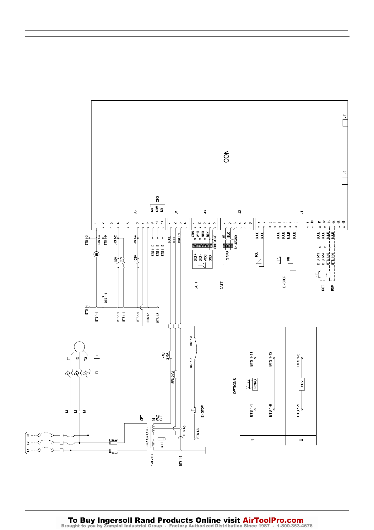
12
UP6 15, UP6 20, UP6 25, UP6 30
http:/air.ingersollrand.com
ESQUEMA ELECTRICO – Directamente en línea (DOL) CON CONTROL INTELLISYS
OPCION INTELLISYS
INTELLISYS – DOL
32343956
Revision D
Page 71

CLAVE
http:/air.ingersollrand.com
UP6 15, UP6 20, UP6 25, UP6 30
OPCION INTELLISYS
13
CON Controlador INTELLISYS
CPT Transformador, control
EDV Válvula de purga eléctrica
E–STOP Botón, parada de emergencia
FU Fusible
M Bobina, arranque del motorContactor (Principal)
1M Bobina, arranque del motor
OL Sobrecarga, arranque del motor
1SV Válvula, solenoide de carga Normalmente Cerrada
3SV Válvula, solenoide de seguridad Normalmente Abierta
10SV Solenoide, sistema/colector
RST Arranque remoto
(opcional)
RSP Rearranque sin corriente
(opcional)
CFO Salida de fallos comunes
PORO Arranque remoto (opcional)
2ATT Sensor de temperatura
3APT Sensor de presión
NOTAS
1. La desconexión o interruptor de circuitos con fusible y aprobados
según los requisitos del código han de ser proporcionados por el
cliente.
2. Las líneas de trazos representan el cableado del cliente.
3. El tamaño de los componentes eléctricos no suministrados por
Ingersoll Rand es responsabilidad del cliente y deberá decidirse
de conformidad con la información facilitada en la chapa de datos
del compresor y en los códigos eléctricos a nivel local.
4. La unidad no arrancará de nuevo automáticamente después de
una interrupción de la potencia, salvo con la opción adicional
PORO.
5. El circuito se muestra en posición normal desactivado.
6. Todo el cableado ha de ser de conformidad con los códigos locales.
Page 72
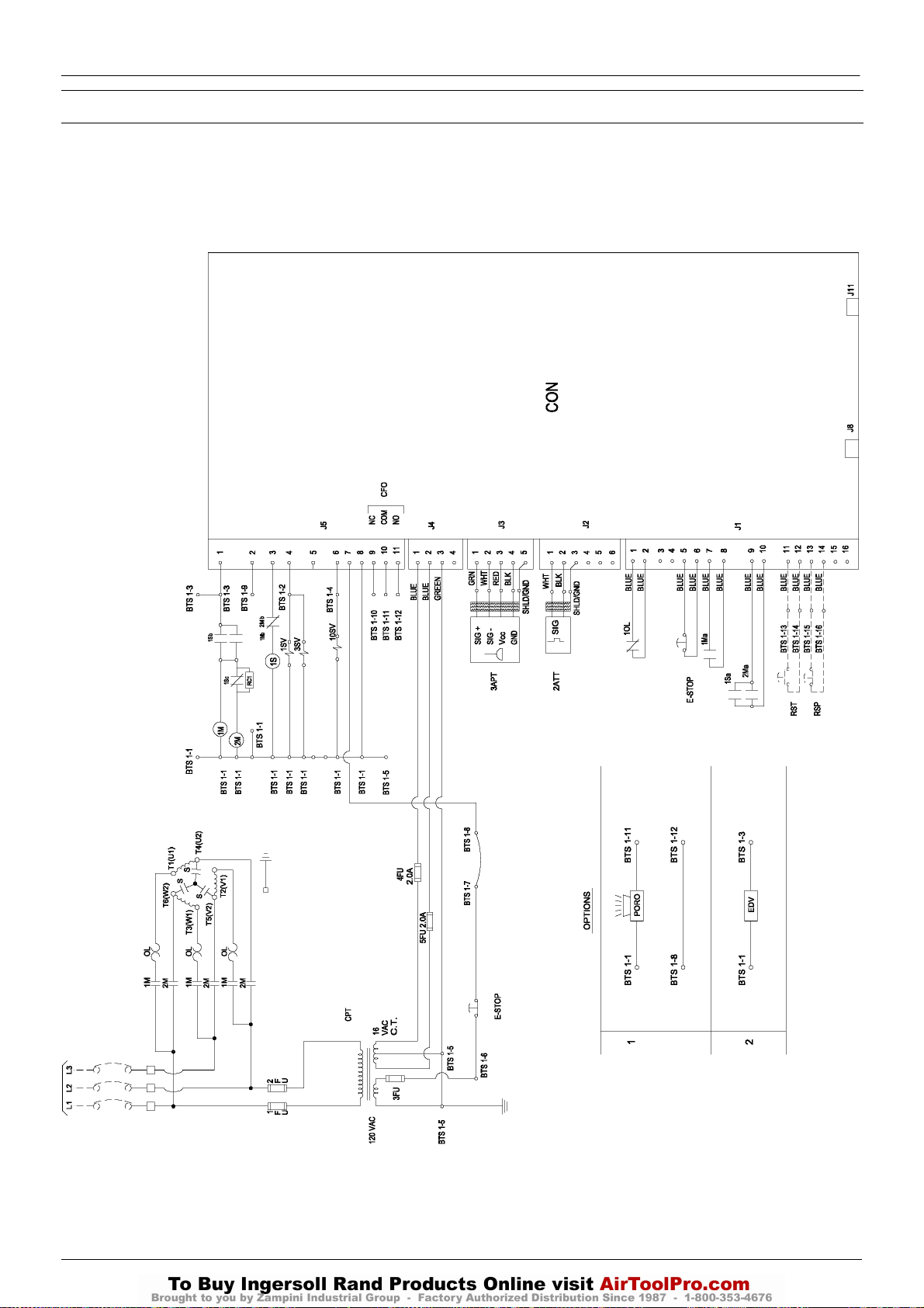
14
UP6 15, UP6 20, UP6 25, UP6 30
http:/air.ingersollrand.com
ESQUEMA ELECTRICO – ESTRELLA TRINAGULO CON CONTROL INTELLISYS
OPCION INTELLISYS
INTELLISYS – STAR DELTA
32343931
Revision E
Page 73

CLAVE
http:/air.ingersollrand.com
UP6 15, UP6 20, UP6 25, UP6 30
OPCION INTELLISYS
15
CON Controlador INTELLISYS
CPT Transformador, control
EDV Válvula de purga eléctrica
E–STOP Botón, parada de emergencia
FU Fusible
1M Bobina, arranque del motorContactor (Principal)
2M Bobina, arranque del motorContactor (Triangulo)
OL Sobrecarga, arranque del motor
1SV Válvula, solenoide de carga Normalmente Cerrada
3SV Válvula, solenoide de seguridad Normalmente Abierta
10SV Solenoide, sistema/colector
RST Arranque remoto
(opcional)
RSP Rearranque sin corriente
(opcional)
CFO Salida de fallos comunes
PORO Arranque remoto (opcional)
2ATT Sensor de temperatura
3APT Sensor de presión
1S Bobina, arranque del motorContactor
(wye / star)
NOTAS
1. La desconexión o interruptor de circuitos con fusible y aprobados
según los requisitos del código han de ser proporcionados por el
cliente.
2. Las líneas de trazos representan el cableado del cliente.
3. El tamaño de los componentes eléctricos no suministrados por
Ingersoll Rand es responsabilidad del cliente y deberá decidirse
de conformidad con la información facilitada en la chapa de datos
del compresor y en los códigos eléctricos a nivel local.
4. La unidad no arrancará de nuevo automáticamente después de
una interrupción de la potencia, salvo con la opción adicional
PORO.
5. El circuito se muestra en posición normal desactivado.
6. Todo el cableado ha de ser de conformidad con los códigos locales.
7. Azul – 16 Voltios CA
Page 74
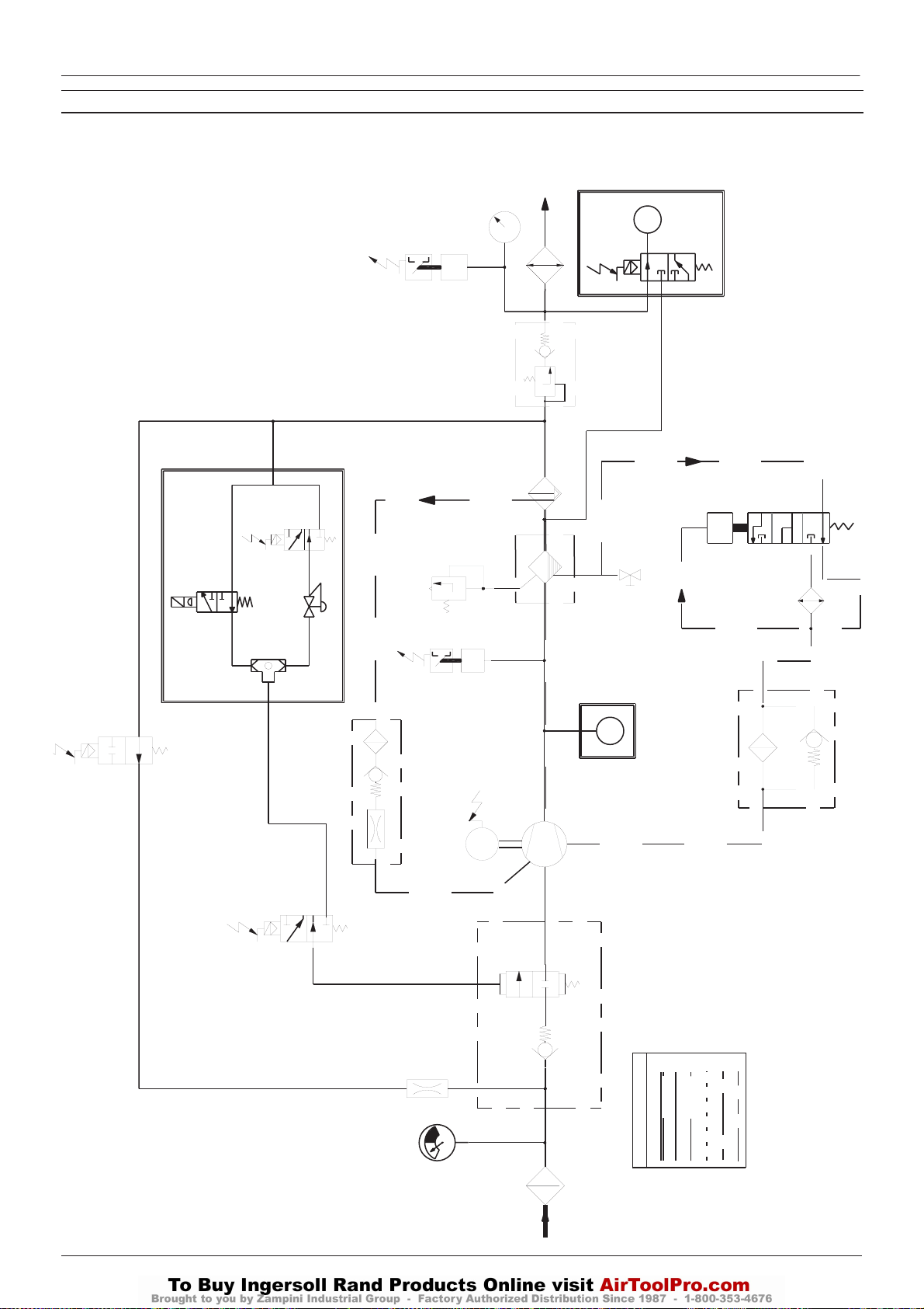
16
UP6 15, UP6 20, UP6 25, UP6 30
http:/air.ingersollrand.com
OPCION INTELLISYS
CONDUCTOS E INSTRUMENTACION CON CONTROL INTELLISYS
6SV
33
32
10SV
85584282
Revision D
INTELLISYS (OPTION)
REPLACES 10 AND 11
5SV
10
CONTINUED IN NEXT PAGE
11
P
39
9
8
7
T
6
40
42
41
17
18
12
T
14
15
3SV
20
19
MODULATION (OPTION)
3
1SV
16
5
21
4
M
34
INTELLISYS (OPTION)
REPLACES 12
B
A
2
PIPING LEGEND
13
F
E
C
D
22
1
Page 75
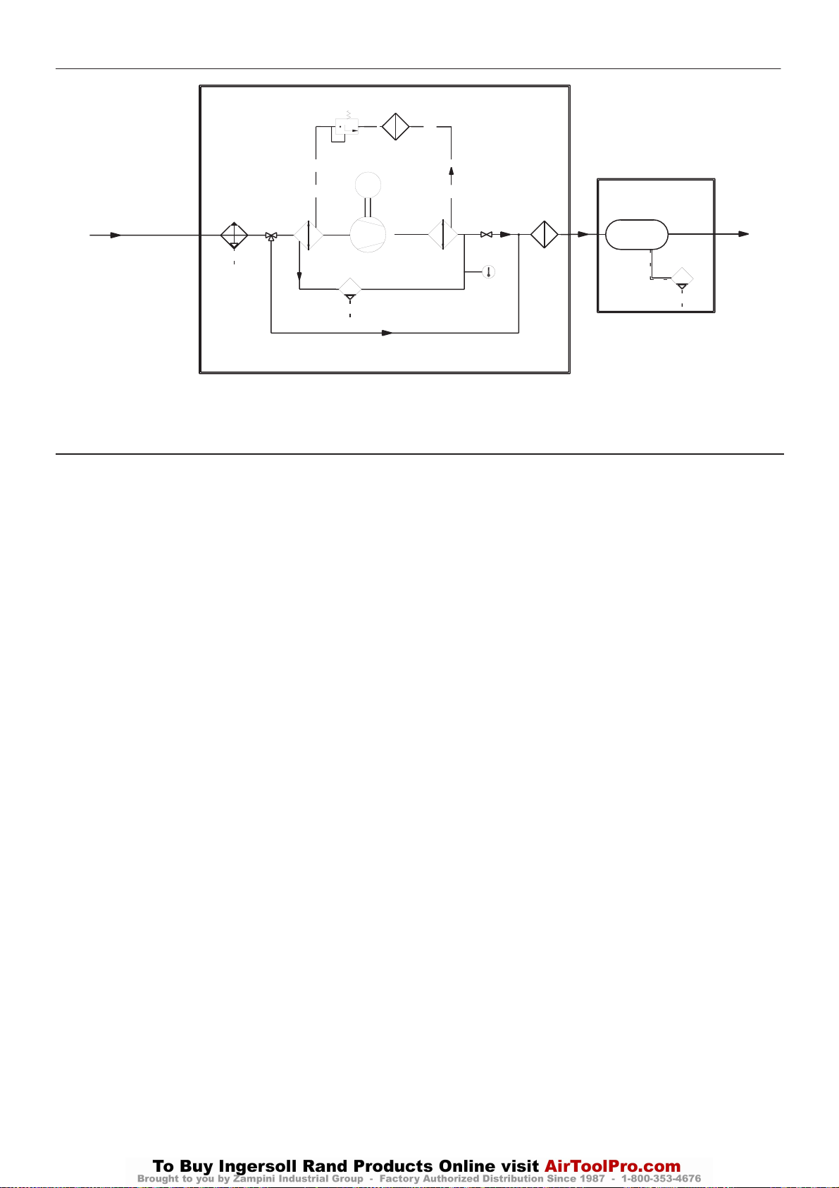
OPCION INTELLISYS
http:/air.ingersollrand.com
UP6 15, UP6 20, UP6 25, UP6 30
17
FROM PREVIOUS PAGE
CLAVE
1. Filtro de aire
2. Válvula entrada
3. Válvula de solenoide
4. Conjunto unidad compresora
5. Motor
6. Filtro basto del tanque separador
7. Separador, fino
8. Válvula de presión mínima
9. Post–enfriador
10.Manómetro
11.Presostato
12.Interruptor de temperatura
13.Filtro del refrigerante
14.Termostato
15.Enfriador
16.Relé de sobrecarga
Motor
17.Válvula de seguridad
18.Válvula de vaciado
19.Pantalla, barrido
20.Válvula de solenoide
21.Orificio
22.Indicador limitación de aire
Kompressori külmutusaine
23.
Aurusti
24.
Kondensaat
25.
27
26
M
35
24
37 38
23
29
25
36
28
INTEGRAL DRYER (OPTION)
Filter, külmutusaine
26.
Paisuklapp
27.
28.
Kondenseerumispunkti indikaator
29.
Kondensaadi dreeniklapp
30.
Õhu survepaak
Automaatne dreeniklapp
31.
32.Válvula de solenoide (línea/cárter)
33.Transductor de presión,
34.Sensor de temperatura
35.Moisture Separator
36.Filter, Air
37.3 Way Valve, Bypass
38.Valve, Isolation
39.Valve, Solenoid 5sv (Modulation)
40.Valve, Solenoid 6sv (Modulation)
41.Valve, Shuttle
42.Valve, Modulation
A Aire/Lubricante
B Aire
C Lubricante
D Condensado
E Límite de componentes
F Refrigerante
G Opcion
30
31
AIR RECEIVER (OPTION)
Page 76
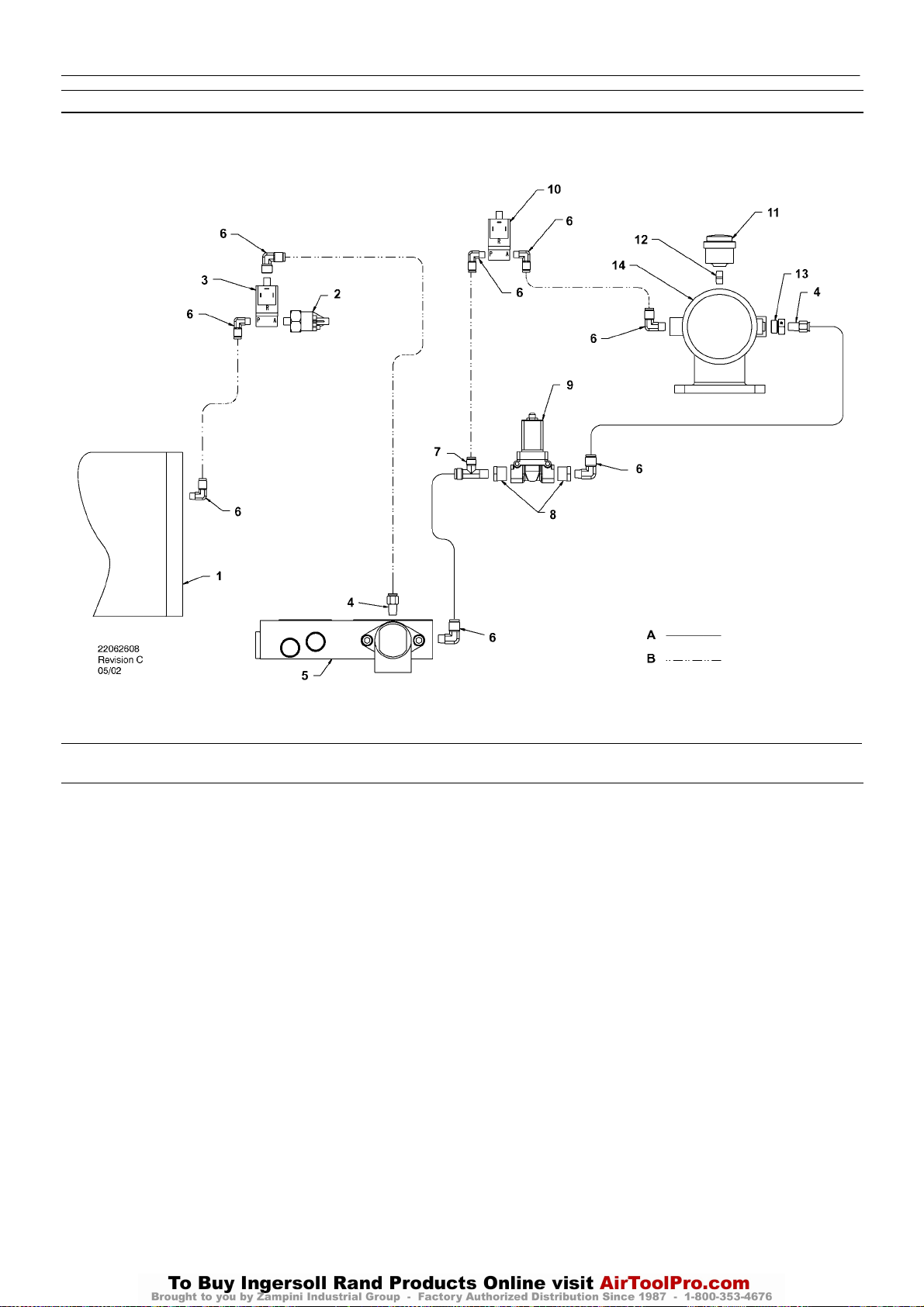
18
UP6 15, UP6 20, UP6 25, UP6 30
http:/air.ingersollrand.com
ESQUEMA DE CONTROL INTELLISYS E INSTRUMENTACION
OPCION INTELLISYS
CLAVE
1. Tanque separador
2. Transductor de presión
3. Solenoide, sistema/colector
4. Conector
5. Colector
6. Codo
7. Unión en “T”, tramo macho
8. Reducción
9. Válvula de solenoide de seguridad
10.Válvula de solenoide de carga
11.Indicador del filtro de aire
12.Manguito
13.Adaptador
14.Válvula, admisión
NOTAS:
A. Tuberías de 3/8 pulgada
B. Tuberías de 1/4 pulgada
Page 77
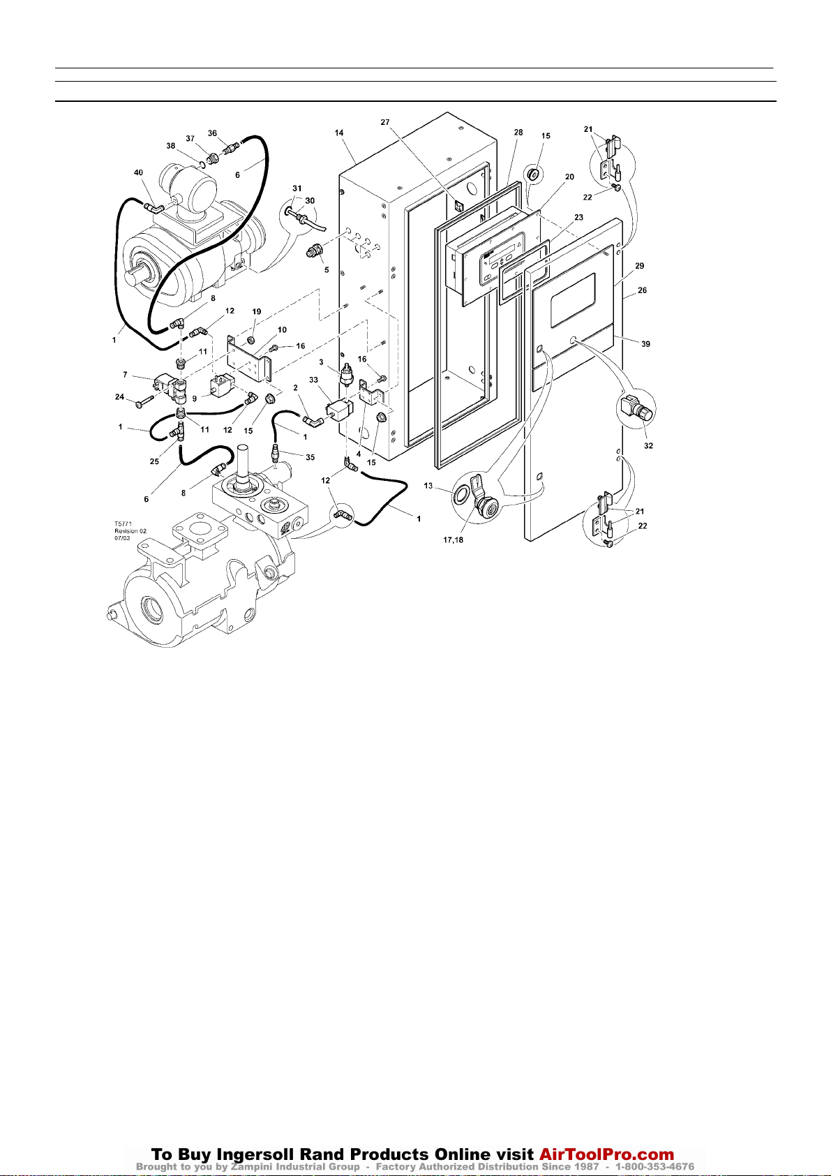
PIEZAS DE INTELLISYS – INSTRUMENTACION Y SISTEMA ELECTRICO
http:/air.ingersollrand.com
UP6 15, UP6 20, UP6 25, UP6 30
OPCION INTELLISYS
19
Elemento ccn Cantidad Descripción Elemento ccn Cantidad Descripción
1 39124813 AR Tubo (Nylon)
2 39155460 1 Codo
3 39853809 1 Transductor
4 22107833 1 Soporte
5 92877018 5 Pasamuros
6 39124821 AR Tubo (Nylon)
7 54654652 1 Válvula de solenoide
8 39155650 2 Codo
9 54774302 1 Válvula de solenoide
10 54755426 1 Soporte
11 95944625 2 Casquillo
12 39155577 4 Codo
13 93492072 2 Sello
14 22177174 1 Mueble
15 96737564 14 Tuerca
16 96743182 8 Tornillo
17 85584340 4 Pestillo
*18 92829308 1 Llave
19 96703756 2 Tuerca
20 22128763 1 Controlador INTELLISYS
21 22091193 2 Bisagra
22 96743992 4 Tornillo
23 39495874 1 Junta
24 96742754 2 Tornillo
25 22055909 1 Te
26 22177190 1 Puerta
27 39133467 3 Montura
28 22177315 1 Junta
29 22131155 1 Calcomanía controlador
30 22137848 1 Sensor, temperature
31 39404157 1 Junta tórica
32 22113344 1 Boton parada emergencia
33 22289797 1 Solenoide, sistema/colector
*34 39192000 4 Pasacable
35 39156393 1 Conector
36 39156419 1 Conector
37 54774997 1 Casquillo
38 39404165 1 Junta tórica
39 22131148 1 Etiqueta
40 39155478 1 Codo
* No dibujado
Page 78
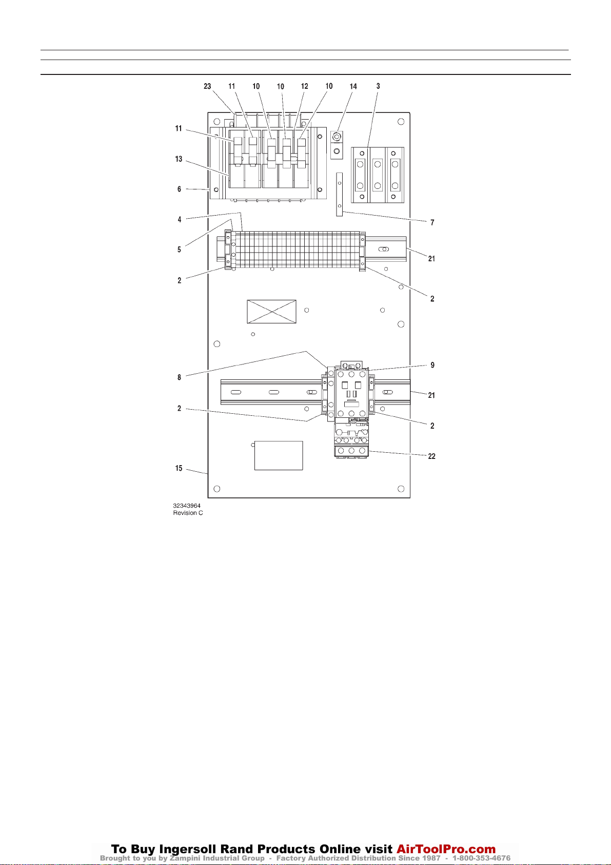
20
UP6 15, UP6 20, UP6 25, UP6 30
http:/air.ingersollrand.com
PIEZAS DE INTELLISYS – C37 TENSION COMPLETA – Directamente en línea (DOL) 60Hz – 575V 15/30cv
OPCION INTELLISYS
Elemento ccn Cantidad Descripción Elemento ccn Cantidad Descripción
1–
2 39252937 4 Bloque, tope final
3 39164520 1 Bloque terminales
4 39252903 27 Bloque terminales
5 39252911 1 Bloque terminales
6 22114623 1 Soporte
7 32342115 1 Bus, puesta a tierra
8 22132963 1 Contacto, auxiliar
9 39251061 1 Contactor – C37
10 22074033 3 Fusibile
2.0A 125–250V
11 32342099 2 Fusibile
1.5A 600V
12 39479035 1 Fusible, portafusible
13 39480504 1 Fusible, portafusible
14 32342123 1 Tierra de corriente
15 22113351 1 Panel
*16 39191648 1 Tapón
11 Posición
*17 39191655 1 Tapón
16 Posición
*18 39186101 1 Tapón
4 Posición
*19 39191630 1 Tapón
5 Posición
*20 39186093 1 Tapón
6 Posición
21 22056741 2 Raíl
22 23053754 1 Relé de sobrecarga
23 39491519 1 Transformador
* No dibujado
Page 79
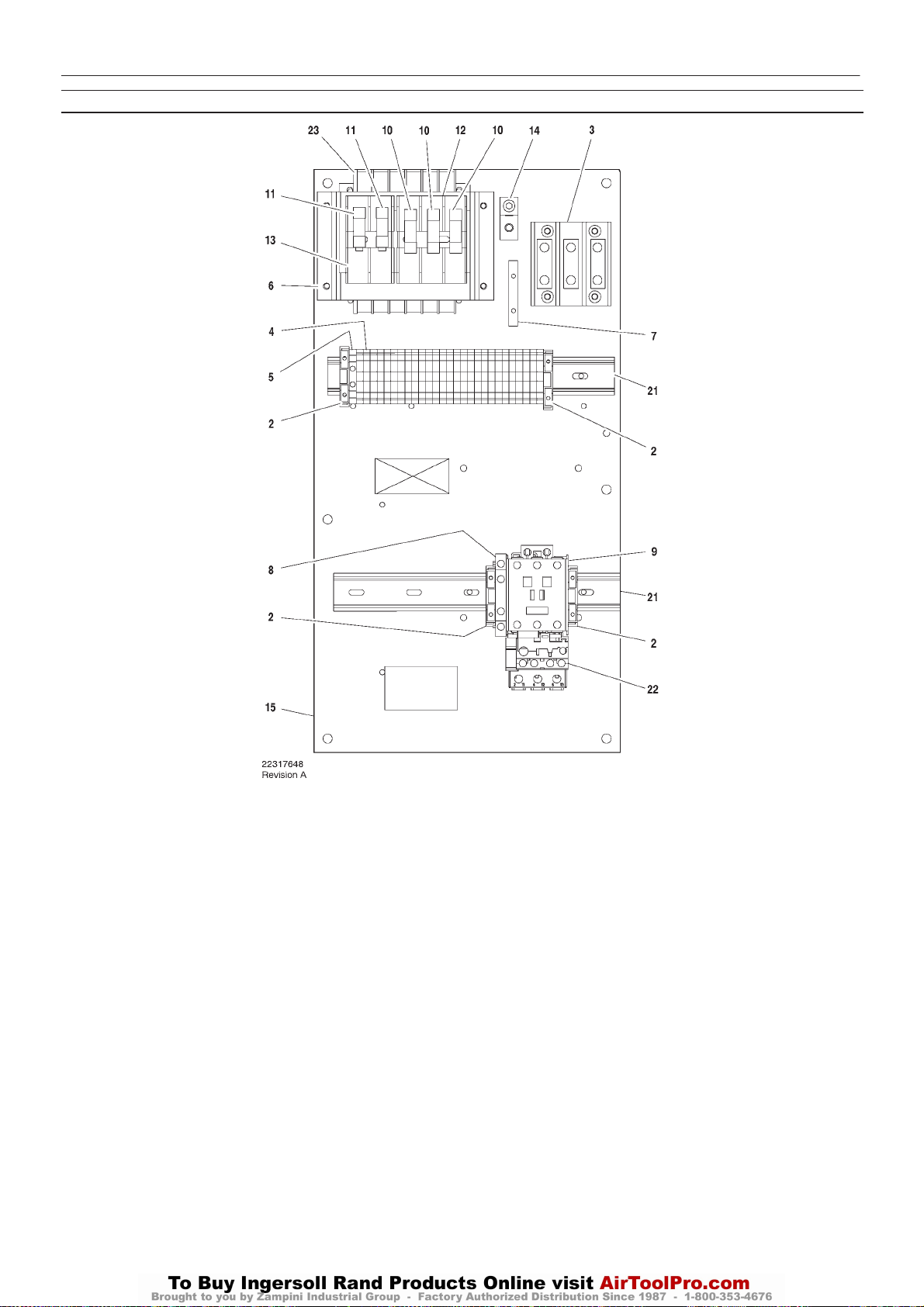
OPCION INTELLISYS
http:/air.ingersollrand.com
UP6 15, UP6 20, UP6 25, UP6 30
PIEZAS DE INTELLISYS – C43 TENSION COMPLETA – Directamente en línea (DOL) 60Hz – 230/460V 15cv
21
Elemento ccn Cantidad Descripción Elemento ccn Cantidad Descripción
1–
2 39252937 4 Bloque, tope final
3 39164520 1 Bloque terminales
4 39252903 27 Bloque terminales
5 39252911 1 Bloque terminales
6 22114623 1 Soporte
7 32342115 1 Bus, puesta a tierra
8 22132963 1 Contacto, auxiliar
9 39250998 1 Contactor
10 22074033 3 Fusibile
2.0A 125–250V
11 32342099 2 Fusibile
1.5A 600V
12 39479035 1 Fusible, portafusible
13 39480504 1 Fusible, portafusible
14 32342123 1 Tierra de corriente
15 22113351 1 Panel
*16 39191648 1 Tapón
11 Posición
*17 39191655 1 Tapón
16 Posición
*18 39186101 1 Tapón
4 Posición
*19 39191630 1 Tapón
5 Posición
*20 39186093 1 Tapón
6 Posición
21 22056741 2 Raíl
22 23053754 1 Relé de sobrecarga
23 39491519 1 Transformador
* No dibujado
Page 80
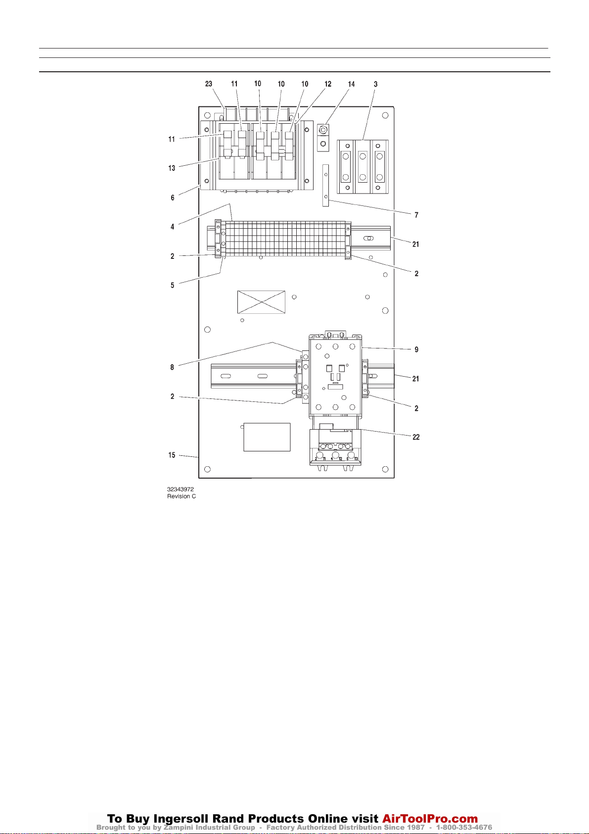
22
UP6 15, UP6 20, UP6 25, UP6 30
http:/air.ingersollrand.com
PIEZAS DE INTELLISYS – C85 TENSION COMPLETA – Directamente en línea (DOL) 60Hz – 200V 15–25cv / 230/460 20–30cv
OPCION INTELLISYS
Elemento ccn Cantidad Descripción Elemento ccn Cantidad Descripción
1–
2 39252937 4 Bloque, tope final
3 39164520 1 Bloque terminales
4 39252903 27 Bloque terminales
5 39252911 1 Bloque terminales
6 22114623 1 Soporte
7 32342115 1 Bus, puesta a tierra
8 22132963 1 Contacto, auxiliar
9 39251020 1 Contactor
10 22074033 3 Fusibile
2.0A 125–250V
11 32342099 2 Fusibile
1.5A 600V
12 39479035 1 Fusible, portafusible
13 39480504 1 Fusible, portafusible
14 32342123 1 Tierra de corriente
15 22113351 1 Panel
*16 39191648 1 Tapón
11 Posición
*17 39191655 1 Tapón
16 Posición
*18 39186101 1 Tapón
4 Posición
*19 39191630 1 Tapón
5 Posición
*20 39186093 1 Tapón
6 Posición
21 22056741 2 Raíl
22 23053770 1 Relé de sobrecarga
23 39491519 1 Transformador
* No dibujado
Page 81
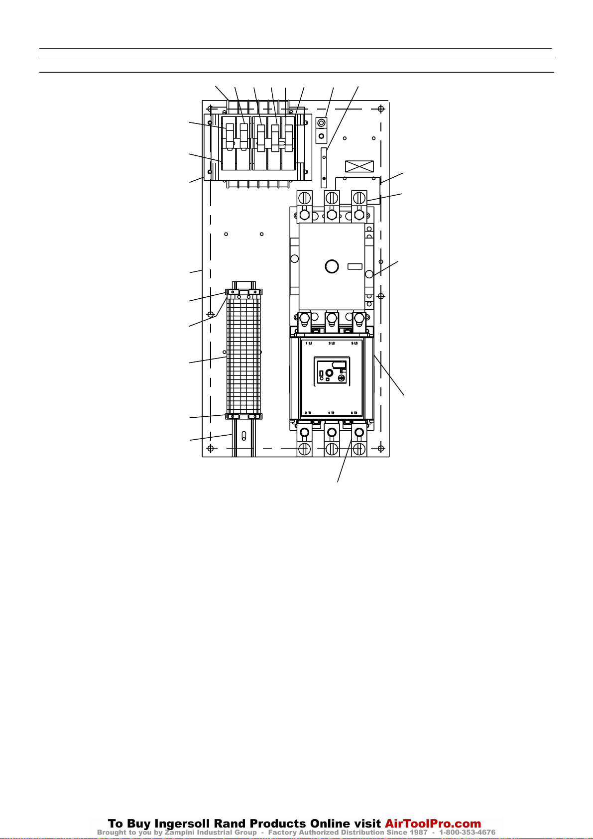
OPCION INTELLISYS
http:/air.ingersollrand.com
UP6 15, UP6 20, UP6 25, UP6 30
PIEZAS DE INTELLISYS – D110 TENSION COMPLETA – Directamente en línea (DOL) 60Hz – 200V 30cv
23
10
24
10
12
6
16
2
3
4
9
9
11
9
7
15
13
5
8
23
2
22
Revision D
Elemento ccn Cantidad Descripción Elemento ccn Cantidad Descripción
*1 22113344 1
2 39252937 2 Bloque, tope final
3 39252911 1 Bloque terminales
4 39252903 27 Bloque terminales
5 22630727 2 Bloque terminales
6 22114623 1 Soporte
7 32342115 1 Bus, puesta a tierra
8 22264873 1 Contactor
9 22074033 3 Fusibile
10 32342099 2 Fusibile
11 39479035 1 Fusible, portafusible
12 39480504 1 Fusible, portafusible
13 1 Patilla
Assembly, emergency stop
push button
2.0A 125–250V
1.5A 600V
532343980
*14 39191648 1 Tapón
11 Posición
15 32342123 1 Tierra de corriente
16 22113351 1 Panel
*17 39191655 1 Tapón
16 Posición
*18 39186101 1 Tapón
4 Posición
*19 39191630 1 Tapón
5 Posición
*20 39186093 1 Tapón
6 Posición
22 22056741 1 Raíl
23 39251095 1 Relé de sobrecarga
24 39491519 1 Transformador
* No dibujado
Page 82
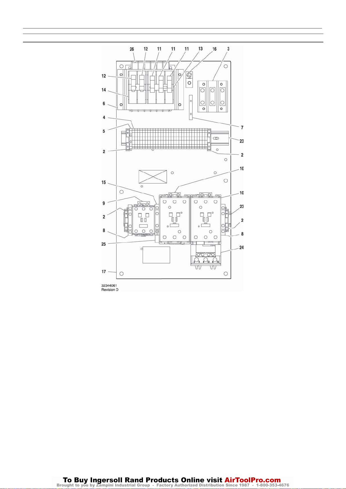
24
UP6 15, UP6 20, UP6 25, UP6 30
http:/air.ingersollrand.com
PIEZAS DE INTELLISYS – C60/C43 ESTRELLA/TRIANGULO – 60Hz – 200V 25/30cv, 220/230V – 30hp
OPCION INTELLISYS
Elemento ccn Cantidad Descripción Elemento ccn Cantidad Descripción
1–
2 39252937 4 Bloque, tope final
3 39164520 1 Bloque terminales
4 39252903 29 Bloque terminales
5 39252911 1
6 22114623 1 Soporte
7 32342115 1 Bus, puesta a tierra
8 22132963 2 Contacto, auxiliar
9 39250998 1 Contactor
10 39251004 2 Contactor
11 22074033 3 Fusibile
12 32342099 2 Fusibile
13 39479035 1 Fusible, portafusible
14 39480504 1 Fusible, portafusible
15 39333257 1 Enclavamiento
Bloque terminales
2.0A 125–250V
1.5A 600V
16 32342123 1 Tierra de corriente
17 22113351 1 Panel
*18 39191648 1 Tapón
11 Posición
*19 39191655 1 Tapón
16 Posición
*20 39186101 1 Tapón
4 Posición
*21 39191630 1 Tapón
5 Posición
*22 39186093 1 Tapón
6 Posición
23 22056741 2 Raíl
24 23053770 1 Relé de sobrecarga
25 39203443 1 Supresor
26 39491519 1 Transformador
* No dibujado
Page 83
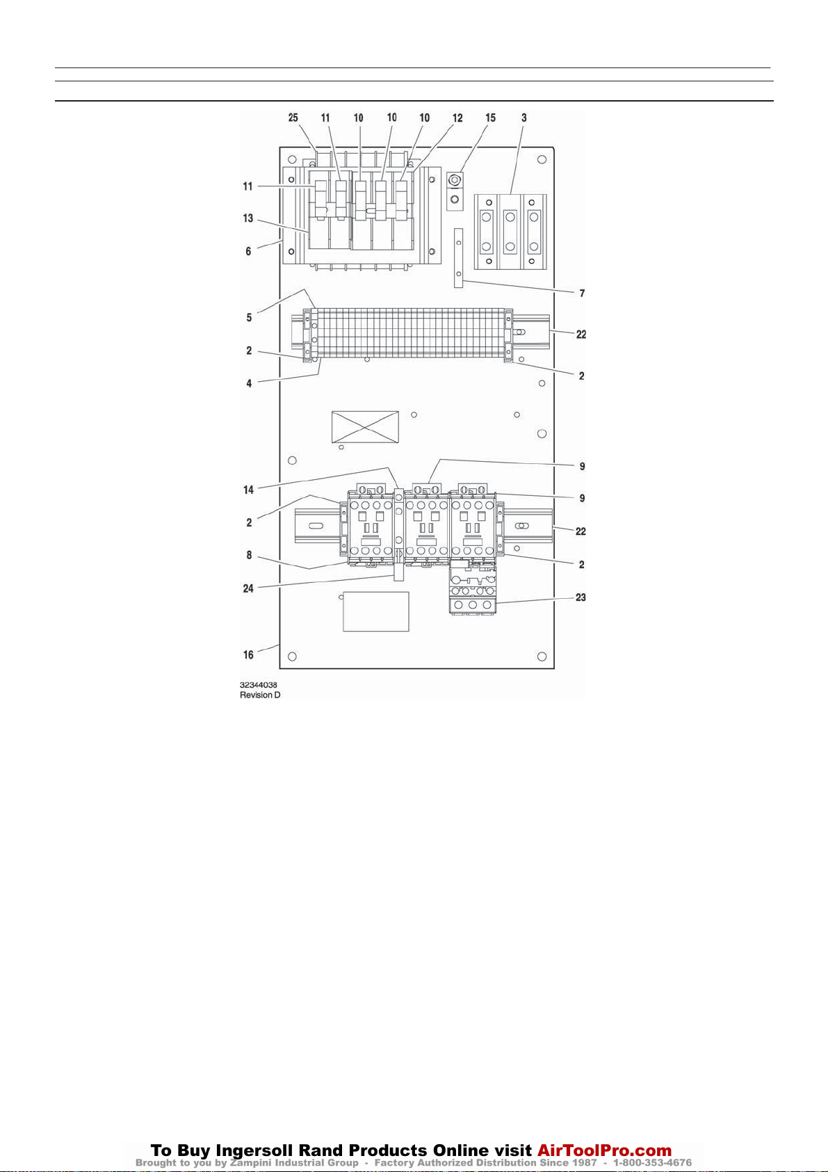
OPCION INTELLISYS
http:/air.ingersollrand.com
UP6 15, UP6 20, UP6 25, UP6 30
PIEZAS DE INTELLISYS – C23/16 ESTRELLA/TRIANGULO – 60Hz – 440/460V - 20/25HP, 575V- 20/30HP
25
Elemento ccn Cantidad Descripción Elemento ccn Cantidad Descripción
1–
2 39252937 4 Bloque, tope final
3 39164520 1 Bloque terminales
4 39252903 30 Bloque terminales
5 39252911 1 Bloque terminales
6 22114623 1 Soporte
7 32342115 1 Bus, puesta a tierra
8 22074413 1 Contactor
9 39252036 2 Contactor
10 22074033 3 Fusibile
2.0A 125–250V
11 32342099 2 Fusibile
1.5A 600V
12 39479035 1 Fusible, portafusible
13 39480504 1 Fusible, portafusible
14 39333257 1 Enclavamiento
15 32342123 1 Tierra de corriente
16 22113351 1 Panel
*17 39191648 1 Tapón
11 Pos ici ón
*18 39191655 1 Tapón
16 Posición
*19 39186101 1 Tapón
4Posición
*20 39191630 1 Tapón
5Posición
*21 39186093 1 Tapón
6Posición
22 22056741 2 Raíl
23 23053747 1 Relé de sobrecarga
24 39203443 1 Supresor
25 39491519 1 Transformador
*Nodibujado
Page 84
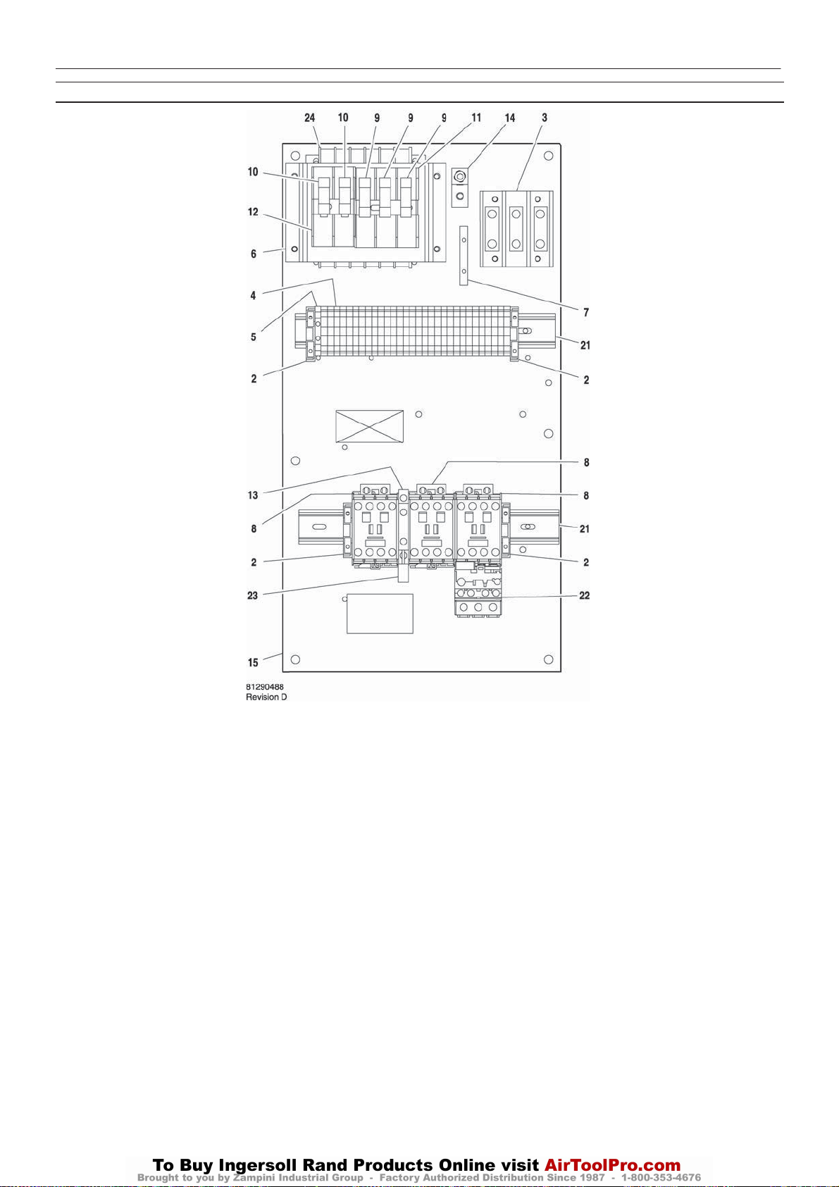
26
UP6 15, UP6 20, UP6 25, UP6 30
http:/air.ingersollrand.com
PIEZAS DE INTELLISYS – C23/23 ESTRELLA/TRIANGULO – 60Hz – 380V 20cv
OPCION INTELLISYS
Elemento ccn Cantidad Descripción Elemento ccn Cantidad Descripción
1–
2 39252937 4 Bloque, tope final
3 39164520 1 Bloque terminales
4 39252903 30 Bloque terminales
5 39252911 1 Bloque terminales
6 22114623 1 Soporte
7 32342115 1 Bus, puesta a tierra
8 39252036 3 Contactor
9 22074033 3 Fusibile
2.0A 125–250V
10 32342099 2 Fusibile
1.5A 600V
11 39479035 1 Fusible, portafusible
12 39480504 1 Fusible, portafusible
13 39333257 1 Enclavamiento
14 32342123 1 Tierra de corriente
15 22113351 1 Panel
*16 39191648 1 Tapón
11 Posición
*17 39191655 1 Tapón
16 Posición
*18 39186101 1 Tapón
4 Posición
*19 39191630 1 Tapón
5 Posición
*20 39186093 1 Tapón
6 Posición
21 22056741 2 Raíl
22 23053747 1 Relé de sobrecarga
23 39203443 1 Supresor
24 39313143 1 Transformador
*Nodibujado
Page 85
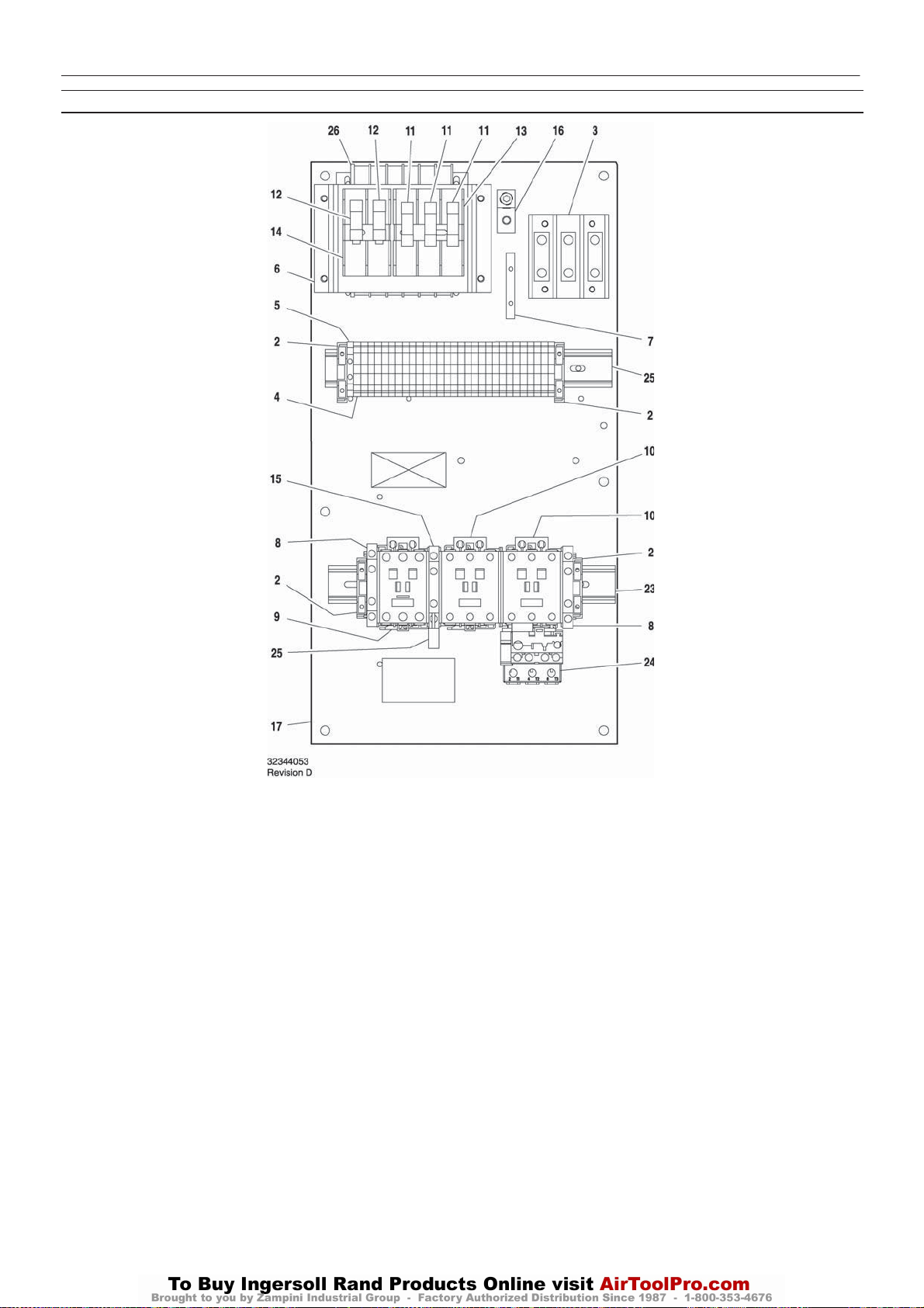
OPCION INTELLISYS
http:/air.ingersollrand.com
UP6 15, UP6 20, UP6 25, UP6 30
PIEZAS DE INTELLISYS – C43/37 ESTRELLA/TRIANGULO – 60Hz – 200V 20cv, 220/230V – 25hp
27
Elemento ccn Cantidad Descripción Elemento ccn Cantidad Descripción
1–
2 39252937 4 Bloque, tope final
3 39164520 1 Bloque terminales
4 39252903 29 Bloque terminales
5 39252911 1 Bloque terminales
6 22114623 1 Soporte
7 32342115 1 Bus, puesta a tierra
8 22132963 2 Contacto, auxiliar
9 39251061 1 Contactor
10 39250998 2 Contactor
11 22074033 3 Fusibile
2.0A 125–250V
12 32342099 2 Fusibile
1.5A 600V
13 39479035 1 Fusible, portafusible
14 39480504 1 Fusible, portafusible
15 39333257 1 Enclavamiento
16 32342123 1 Tierra de corriente
17 22113351 1 Panel
*18 39191648 1 Tapón
11 Posición
*19 39191655 1 Tapón
16 Posición
*20 39186101 1 Tapón
4 Posición
*21 39191630 1 Tapón
5 Posición
*22 39186093 1 Tapón
6 Posición
23 22056741 2 Raíl
24 23053754 1 Relé de sobrecarga
25 39203443 1 Supresor
26 39491519 1 Transformador
*Nodibujado
Page 86
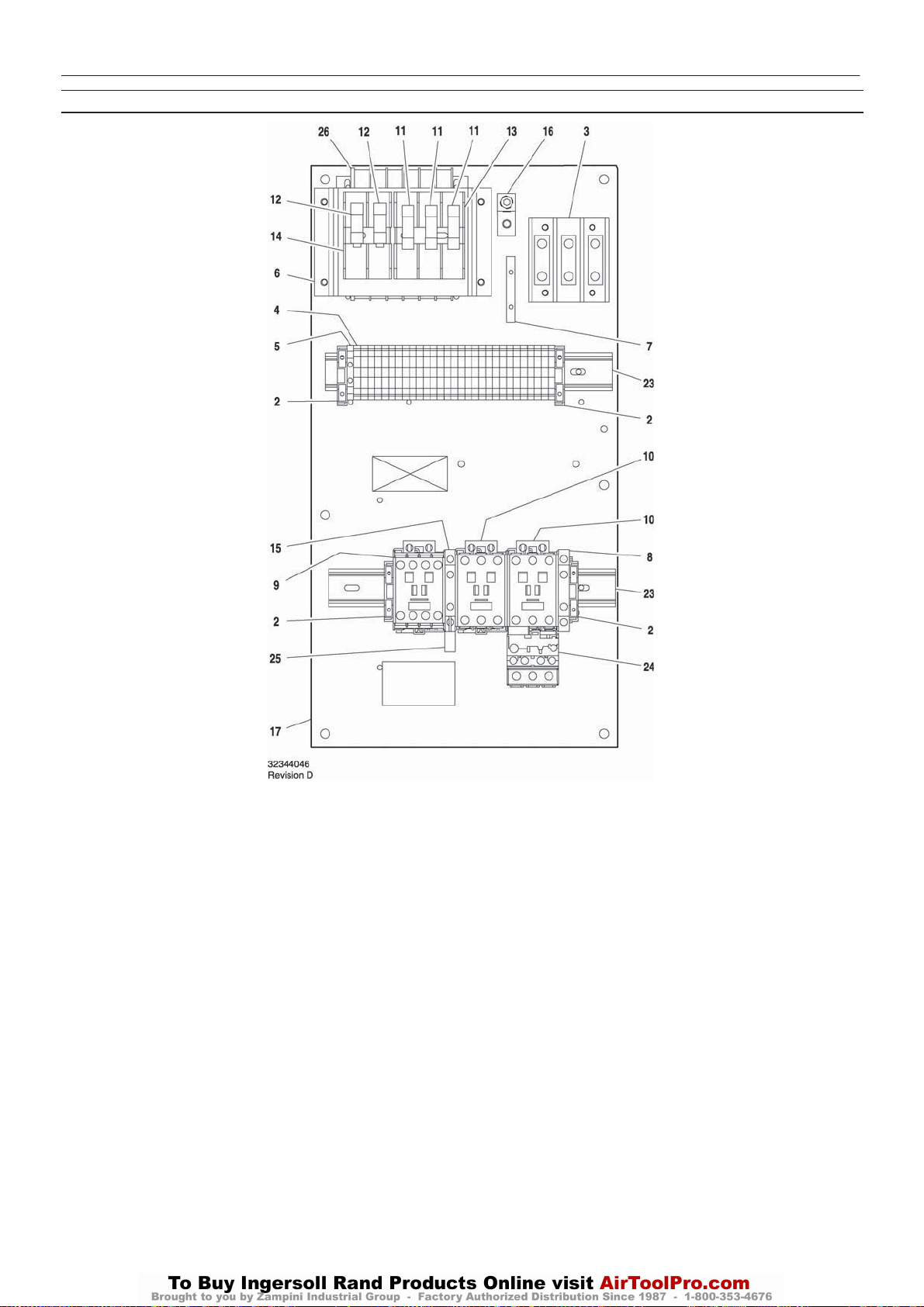
28
UP6 15, UP6 20, UP6 25, UP6 30
http:/air.ingersollrand.com
PIEZAS DE INTELLISYS – C37/23 ESTRELLA/TRIANGULO – 60Hz – 220/230V – 15–20cv, 440/460V – 30hp
OPCION INTELLISYS
Elemento ccn Cantidad Descripción Elemento ccn Cantidad Descripción
1–
2 39252937 4 Bloque, tope final
3 39164520 1 Bloque terminales
4 39252903 29 Bloque terminales
5 39252911 1 Bloque terminales
6 22114623 1 Soporte
7 32342115 1 Bus, puesta a tierra
8 22132963 1 Contacto, auxiliar
9 39252036 1 Contactor
10 39251061 2 Contactor
11 22074033 3 Fusibile
2.0A 125–250V
12 32342099 2 Fusibile
1.5A 600V
13 39479035 1 Fusible, portafusible
14 39480504 1 Fusible, portafusible
15 39333257 1 Enclavamiento
16 32342123 1 Tierra de corriente
17 22113351 1 Panel
*18 39191648 1 Tapón
11 Posición
*19 39191655 1 Tapón
16 Posición
*20 39186101 1 Tapón
4 Posición
*21 39191630 1 Tapón
5 Posición
*22 39186093 1 Tapón
6 Posición
23 22056741 2 Raíl
24 23053754 1 Relé de sobrecarga
25 39203443 1 Supresor
26 39491519 1 Transformador
220/230V & 440/460V
* No dibujado
Page 87
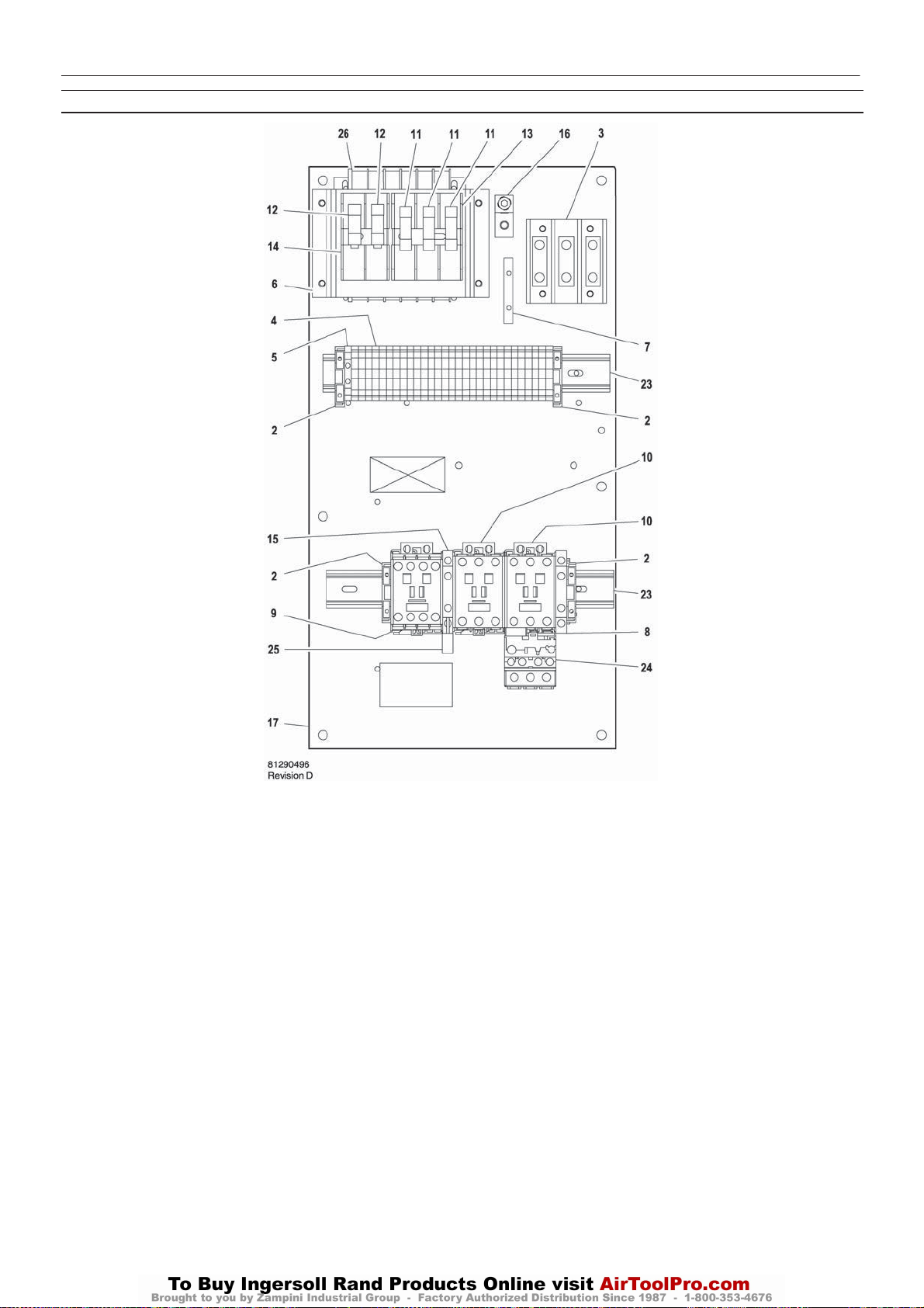
PIEZAS DE INTELLISYS – C37/23 ESTRELLA/TRIANGULO – 60Hz – 380V – 25/30hp
http:/air.ingersollrand.com
UP6 15, UP6 20, UP6 25, UP6 30
OPCION INTELLISYS
29
Elemento ccn Cantidad Descripción Elemento ccn Cantidad Descripción
1–
2 39252937 4 Bloque, tope final
3 39164520 1 Bloque terminales
4 39252903 29 Bloque terminales
5 39252911 1 Bloque terminales
6 22114623 1 Soporte
7 32342115 1 Bus, puesta a tierra
8 22132963 1 Contacto, auxiliar
9 39252036 1 Contactor
10 39251061 2 Contactor
11 22074033 3 Fusibile
2.0A 125–250V
12 32342099 2 Fusibile
1.5A 600V
13 39479035 1 Fusible, portafusible
14 39480504 1 Fusible, portafusible
15 39333257 1 Enclavamiento
16 32342123 1 Tierra de corriente
17 22113351 1 Panel
*18 39191648 1 Tapón
11 Posición
*19 39191655 1 Tapón
16 Posición
*20 39186101 1 Tapón
4 Posición
*21 39191630 1 Tapón
5 Posición
*22 39186093 1 Tapón
6 Posición
23 22056741 2 Raíl
24 23053754 1 Relé de sobrecarga
25 39203443 1 Supresor
26 39313143 1 Transformador
380V
* No dibujado
Page 88
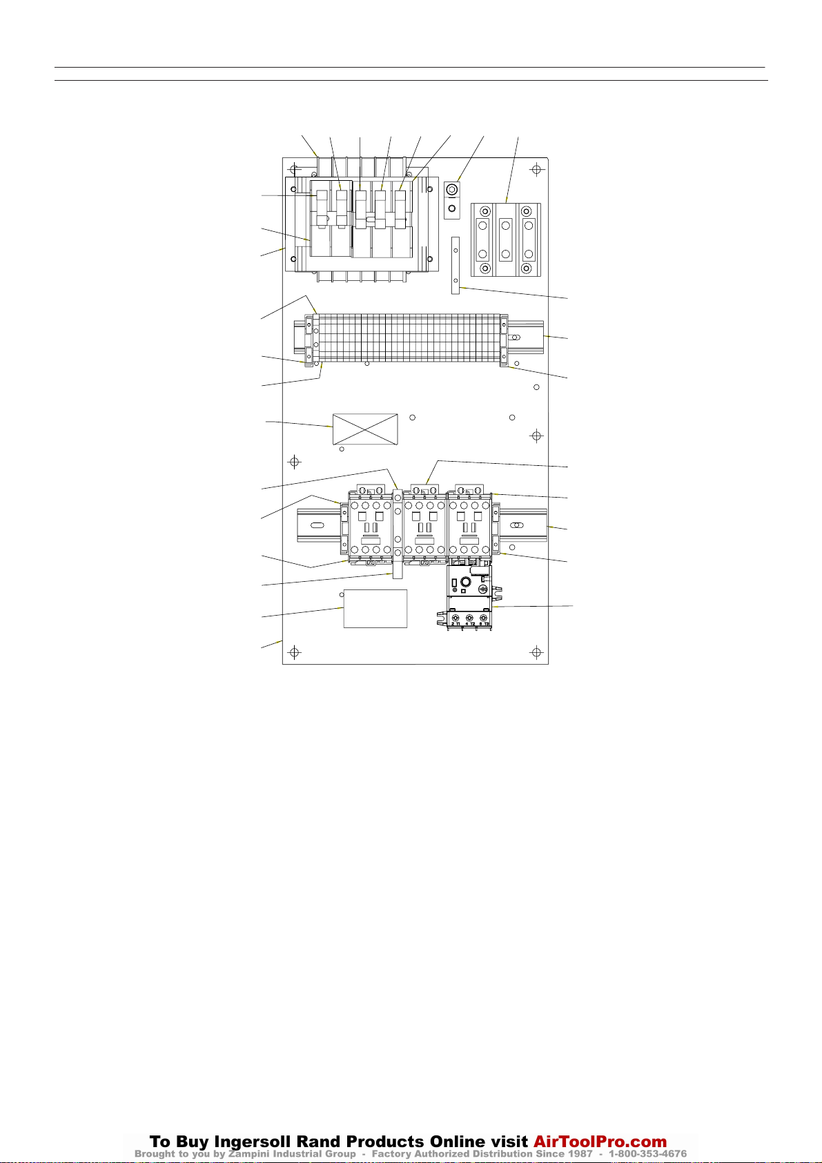
30
UP6 15, UP6 20, UP6 25, UP6 30
http:/air.ingersollrand.com
ASSEMBLY, STARTER C23/C16 60Hz SD (INTELLISYS) 575V
OPCION INTELLISYS
12
10
5
4
24
2
I-R PART
NUMBER AND
REV LEVEL
13
24
7
25
14
26
12
11
11
11
3
15
9
6
22
24
8
8
22
24
23
22650550
Revision B
Elemento ccn Cantidad Descripción Elemento ccn Cantidad Descripción
1
2 39252903 30
3 39164520 1
4 39252911 1
5 22114623 1 Bracket, Fuse Block
6 32342115 1 Bus, Grounding
7 22074413 1 Contactor, C16
8 39252036 2 Contactor, C23
9 39479035 1
10 39480504 1
11 22074033 3 25-250V 2.0A
12 32342099 2 Fuse, 600V 1.5A Primary
13 39333257 1 Interlock, Mechanical
14 1 Label,UL&CUL
-
Bloque terminales
Bloque terminales
Bloque terminales
Fusible, portafusible
Fusible, p
Fusible,
16
ortafusible
15 32342123 1 Lug, Grounding
16 22113351 1 Panel
17 39191648 1
18 39191655 1
19 39186101 1
20 39191630 1
21 39186093 1
22 22056741 2 Rail, Din
23 23053739 1
24 39252937 4 Stop, DinRail
25 39203443 1 Suppressor, Arc
26 39491519 1 T
* Not illustrated
11 Pos ición
Ta p ón
16 Pos ición
Ta p ón
4 Posición
Ta p ón
5 Posición
Ta p ón
6 Posición
Ta p ón
Relé de sobrecarga
ransformer, Control Multi
Page 89
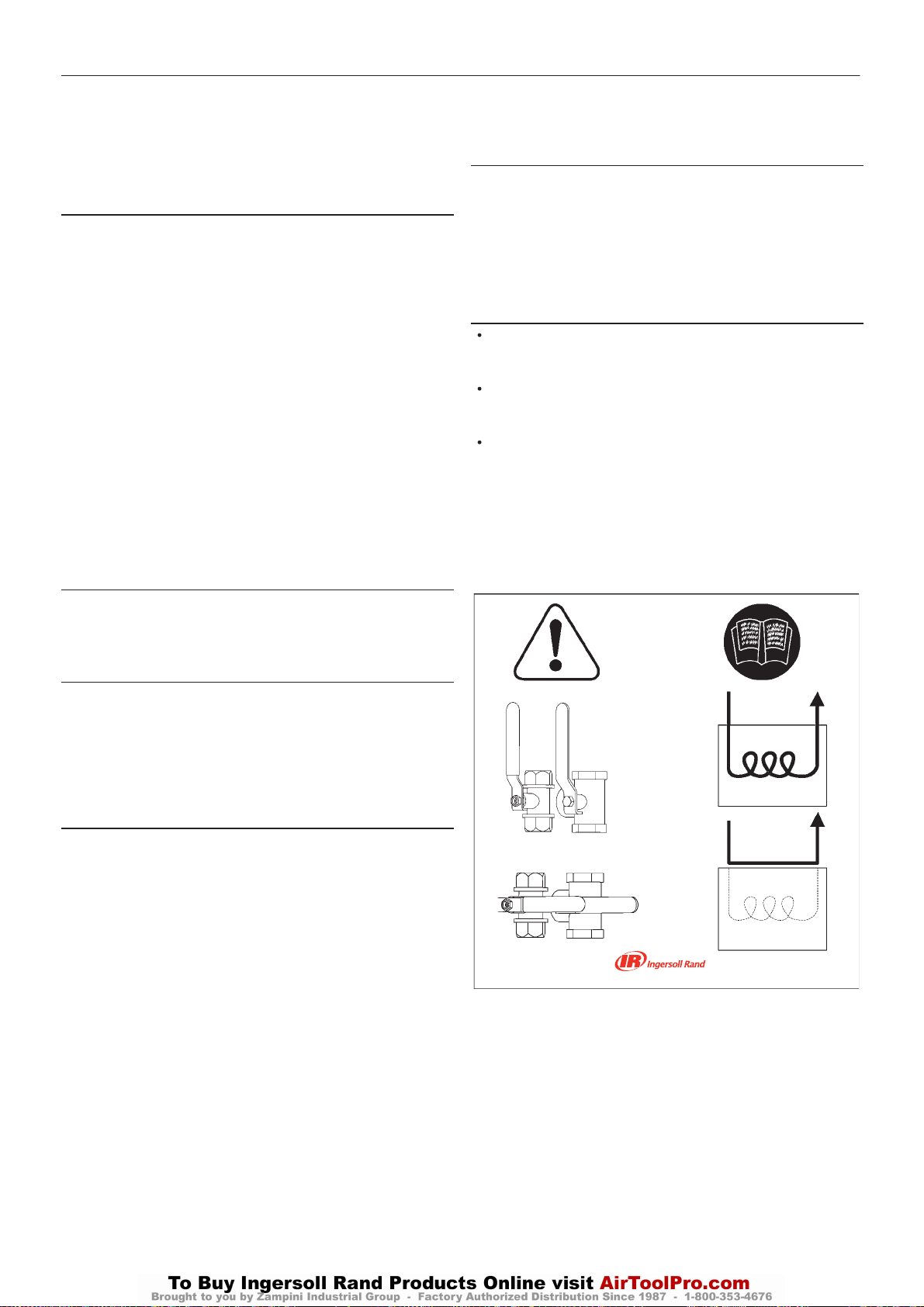
OPCION DE SECADOR 31
http:/air.ingersollrand.com
UP6 15, UP6 20, UP6 25, UP6 30
El secador integrado de la serieUPseries no es para utilizarlo con
las opciones de módulo de baja temperatura ambienteoalaire
libre.
INSTALACION
a) No obstruir las rejillas de aire del secador.
b) Dejar separación suficiente alrededor de la unidad para facilitar el
mantenimientoy asegurar la descarga de aire sin impedimentos desde
el condensador.
c) Evitar la recirculacióndelaire caliente del condensador a la entrada
de aire del condensador.
d) No conectar desagües de condensado en común con otros
conductos de desagüe presurizados en un circuito cerrado. Cerciorarse
de que la salida desde los desagües del condensado no se obstaculice.
Conectar los conductos del condensado de forma que se mantengan los
niveles seguros al mínimo durante el desagüe. Cerciorarse de que el
condensado se elimina de manera responsable de conformidad con las
normas locales de protecció ndelmedioambiente.
e) El aire ambiental alrededor del secador y del compresor no ha de
contener contaminantes sólidos ni gaseosos. Todos los gases
comprimidos y condensados pueden generar ácidos o productos
químicos que pueden dañar el compresor o los componentes del interior
del secador.
Adoptar medidas especiales con el azufre, amoníaco, cloro e
instalaciones en entornos marinos. Para mayor asesoramiento o
asistencia, consulten al representante local de Ingersoll Rand.
CONEXIÓN ELECTRICA
El secador se alimenta desde un suministro monofásico que ha de
proveerse por separado con respecto al suministro trifásico del
compresor. El secador ha de conectarse a un suministro monofásico de
conformidad
DESAGÜES DEL CONDENSADO
El paquete del secador está dotado de tres desagües automáticos del
condensado con flotador en el separador de la humedad, en el
compresor del secador y en el postfiltro. Cada desagüe con flotador
cuenta en el paquete con una salida de desagüe cercana del conjunto.
con los requisitosycódigos locales.
Después de parar el secador, esperar 3 minutos, como mínimo, antes
de ponerlo en marcha otra vez.
PARADA DEL SECADOR
a) Usar el interruptor para parar el secador (Fig.2b).
b) Parar el secador, como mínimo,2minutos después de parar el
compresor de aireodeinterrumpirelflujodeaire al secador.
El aire comprimido nunca deberá penetrar en el secado cuando éste esté
desconectado o cuando se encuentre en una situación de alarma que
pare el compresor de refrigeración.
El secador se puede circunvalar en estas condiciones.
FUNCIONAMIENTO
El secador funciona automáticamente. Se ha fijado en fábrica para
un punto de rocíode3oC(37oF) (ISO7183, Parte 2) y, por consiguiente,
no precisa calibraciónadicional.
Para obtener el máximo rendimiento del secador, respétese el programa
de mantenimiento.
El termómetro de punto de rocío ofrece una orientación sobre el
rendimiento del secador. Cuando se desconecta el secador la
visualización quedará en la secciónroja. Bajocondiciones normales de
trabajolavisualizació n deberá quedar en la sección verde. Si la unidad
continúa funcionando en la secciónroja, póngase en contacto con el
representantelocal de Ingersoll Rand.
La Figura 1 muestra los circuitos de refrigeraciónyaire del secador.
ESTOS CONDUCTOS HAN DE MANTENERSE SEPARADOS.
Uniéndolos se ocasionaría un funcionamiento defectuoso.
ARRANQUE Y FUNCIONAMIENTO
Comprobaciones preliminares
Antes de poner en marcha el compresor, cerciorarse de que:
La alimentacióneléctrica es correcta para la tensión del secador.
Arranque del secador
a) Usar el interruptor verde para poner en marcha el secador (Fig.2b).
b) Para proteger el equipo del secador, arrancar siempre el secador
antes de activar el compresor de aire.
c) Esperar unos 5 minutos hasta que el secador esté funcionando con
las correctas temperatura y presiones de trabajo, antes de arrancar el
compresor.
d) Dejar siempre el secador funcionando mientras el compresor estéen
funcionamiento,independientemente de la condición de carga.
Con el findecircunvalar el secador, parar el compresor UP y bloquearlo
yetiquetarlo. Girar AMBAS válvulas hasta una posiciónhorizontal, tal
como se muestra. El compresor se puede operar y el secador se puede
retirar del sistema para repararlo en modo de circunvalación.
No operarlo con las válvulas en posiciones distintas a las que se
muestran aquí. Esto podría presurizar el secador sinflujodeaire.
Page 90
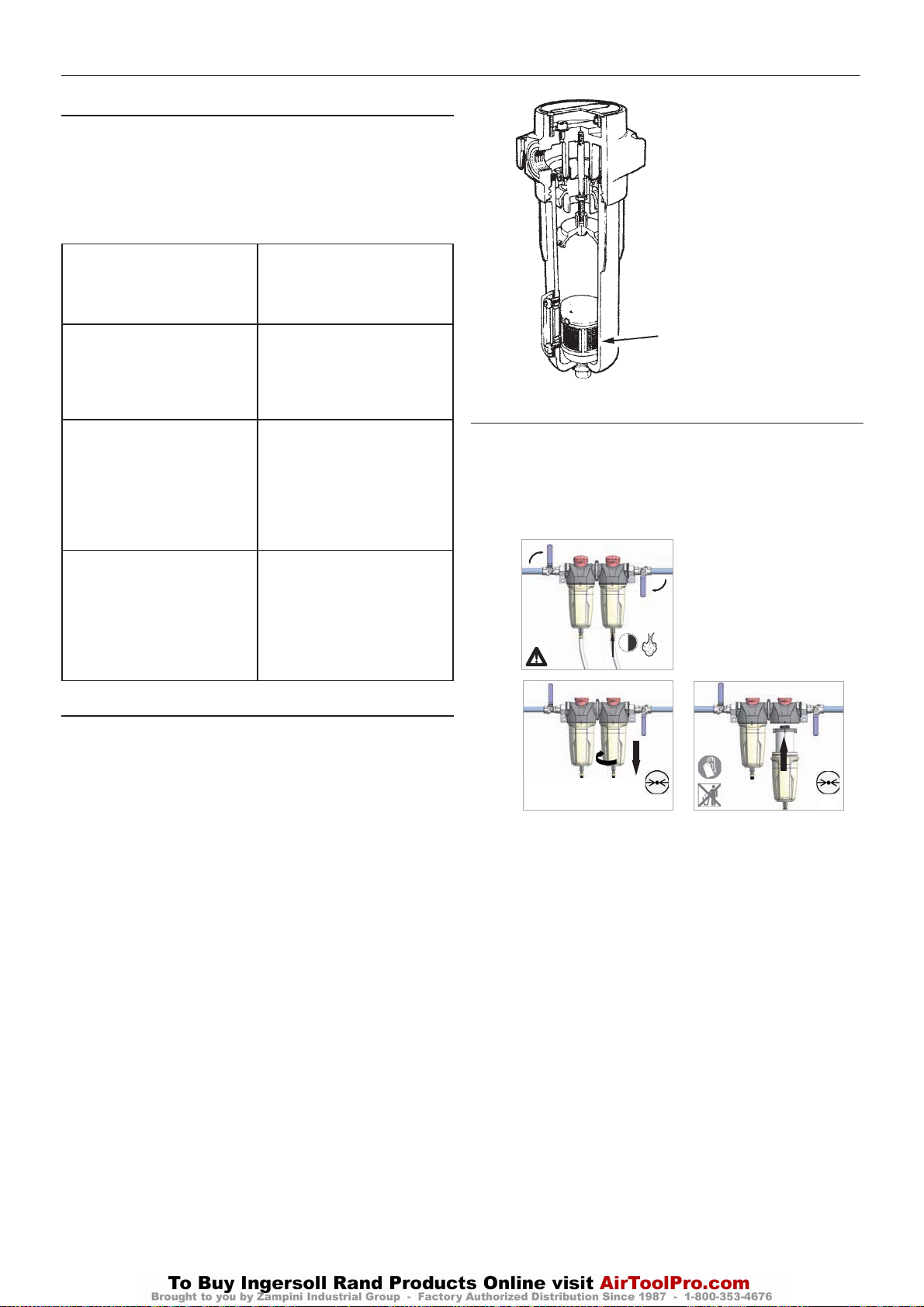
32
UP6 15, UP6 20, UP6 25, UP6 30
http:/air.ingersollrand.com
OPCION DE SECADOR
MANTENIMIENTO
Antes de acceder a piezas eléctricas, desconectar la alimentación
eléctrica al secador utilizando el interruptor de desconexióno
desconectando las conexiones de cables.
Mantenimiento preventivo
Para obtener óptimo rendimiento del secador, respétese el programa de
mantenimientoperiódico que se describe a continuación:
SEMANALMENTE DESAGÜES DEL
CONDENSADO
Comprobar que los desagües del
condensado funcionan
correctamente.
MENSUALMENTE COMPRESOR
Cerciorarse de que la
temperatura del compresor
refrigerante quede por debajode
60oC (140oF) cuando esté
funcionando.
CADA 4 MESES CONDENSADOR
Limpiar el polvo acumulado en las
aletas del condensador.
COMPRESOR
Cerciorarse de que el consumo
de energía del compresor cumple
lo especificado en la chapa de
datos.
ANUALMENTE DESAGÜES DEL
CONDENSADO
Desmontar por completo los
desagües y limpiar todos sus
componentes.
FILTRO DE AIRE
Cambiar el elemento del filtro de
aire.
MANTENIMEINTO DEL SEPARADOR DE LA HUMEDAD
El separador de la humedad funcionaráindefinidamente bajo
condiciones normales de trabajo, aunque en algún momento tal vez se
requiera cambiar las juntas de estanqueidad en caso de que la carcasa
mostrase fugas.
1. Aislar la carcasa del suministro de aire.
2. Eliminar por completo la presión de la cubeta de desagüe según
proceda.
3. Desenroscar la cubeta y retirarla. Si no se ha liberado la presiónde
la cubeta por completo, el aire se escapará por el agujero de aviso
produciendouna alarma sonora. Enroscar otra vez la cubeta y repetirla
instrucción2antesdeintentarlo de nuevo. Si se experimenta resistencia
al desenroscarla, se provee una llave en forma de ’C’ que encajaenlos
refuerzos de la cubeta.
4. Comprobar el estado de las juntas de estanqueidad de la cubeta y
cambiarlas si fuere necesario. Limpiar las roscas.
5. El conjunto de desagüe automático no es apto de servicio y deberá
cambiarse por completo si está defectuoso.
6. Montar otra vez la cubeta junto con la junta tórica.
7. Someterla a presión de nuevo y comprobar si sufre fugas. En caso
positivo, lo más probable es que ocurran por la junta tórica de la cubeta.
Eliminar la presióndelacarcasayquitar la junta tórica e inspeccionar
ylimpiar. Cerciorarse de que las superficies coincidentes esténlimpias
y luego montar la junta tórica y someter a presión otra vez.
Conjunto de desagüeautomático
MANTENIMIENTO DEL FILTRO DE AIRE
Con el fin de asegurar la óptima calidad del aire, deberá cambiarse el
filtro de aire como se indica a continuación. (Los elementos del filtro
usados deberán desecharse de conformidad con las normas locales).
Utilizar únicamente elementos de repuesto genuinos de Ingersoll Rand.
2
1
2
3
> 30s
0 bar
0 psi
5
0 bar
0 psi
4
2
1
Page 91
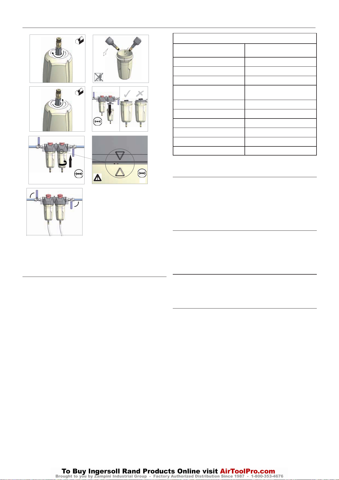
OPCION DE SECADOR
http:/air.ingersollrand.com
UP6 15, UP6 20, UP6 25, UP6 30
33
5 6
1
7 8
0 bar
0psi
9 10
2
1
0 bar
0psi
12
1
2
0 bar
0psi
DESMONTAJE DE LA UNIDAD
La unidad ha sido concebida y fabricada para garantizar un
funcionamientocontinuo.
La larga duración en servicio de algunos componentes, tales como el
ventilador y el compresor, está en función de un buen mantenimiento.
La unidad sólo deberá ser desmontada por un especialista en
refrigeración.
El líquido refrigerante y el aceite lubricante del interior del circuito de
refrigeración han de recuperarse de conformidad con las normas
actuales del país en el que la máquina sea instalada.
DESMONTAJE DE RECICLAJE
Bastidor y paneles
Cambiador de calor (refrigerador) Cobre
Tuberías Cobre
Sistema de desagüe Poliamida
Aislamiento del cambiador de
calor
Aislamiento de tuberías Goma sintética
Compresor Acero / cobre / aluminio/aceite
Condensador Acero / cobre / aluminio
Refrigerante
Válvula Latón
Cable eléctrico Cobre / PVC
FUGAS DE REFRIGERANTE EN EL CIRCUITO DE
REFRIGERACION
La unidad se despacha ya cargada y en perfectas condiciones de
trabajo.
Las fugas de refrigerante se pueden identificar mediante la desconexión
del protector de sobrecargas del compresor (SK).
SI SE DETECTA UNA FUGA EN EL CIRCUITO DE REFRIGERACION,
SOLICITE ASISTENCIA TECNICA.
CARGA DE REFRIGERANTE
ESTA OPERACION SOLO DEBERA REALIZARLA UN
ESPECIALISTA EN REFERIGERACION.
CUANDO SE REPARE EL CIRCUITO DE REFRIGERACION,
RECOGER TODO EL REFRIGERANTE EN UN RECIPINTE Y
DESECHARLO DE LA MANERA APROPIADA.
CARACTERISTICAS DEL REFRIGERANTE R134A
Bajo condiciones normales de temperatura y presión, el citado
refrigerantees un gas incoloro de la clase A1/A1 gas con un valor TVL
de 1.000ppm (clasificación de ASHRAE).
Si ocurre una fuga de refrigerante, ventilar bien la sala antes de
comenzar trabajo alguno.
Acero / poliéster de resina
epoxidica
EPS (poliestireno sinterizado)
R134a
Page 92
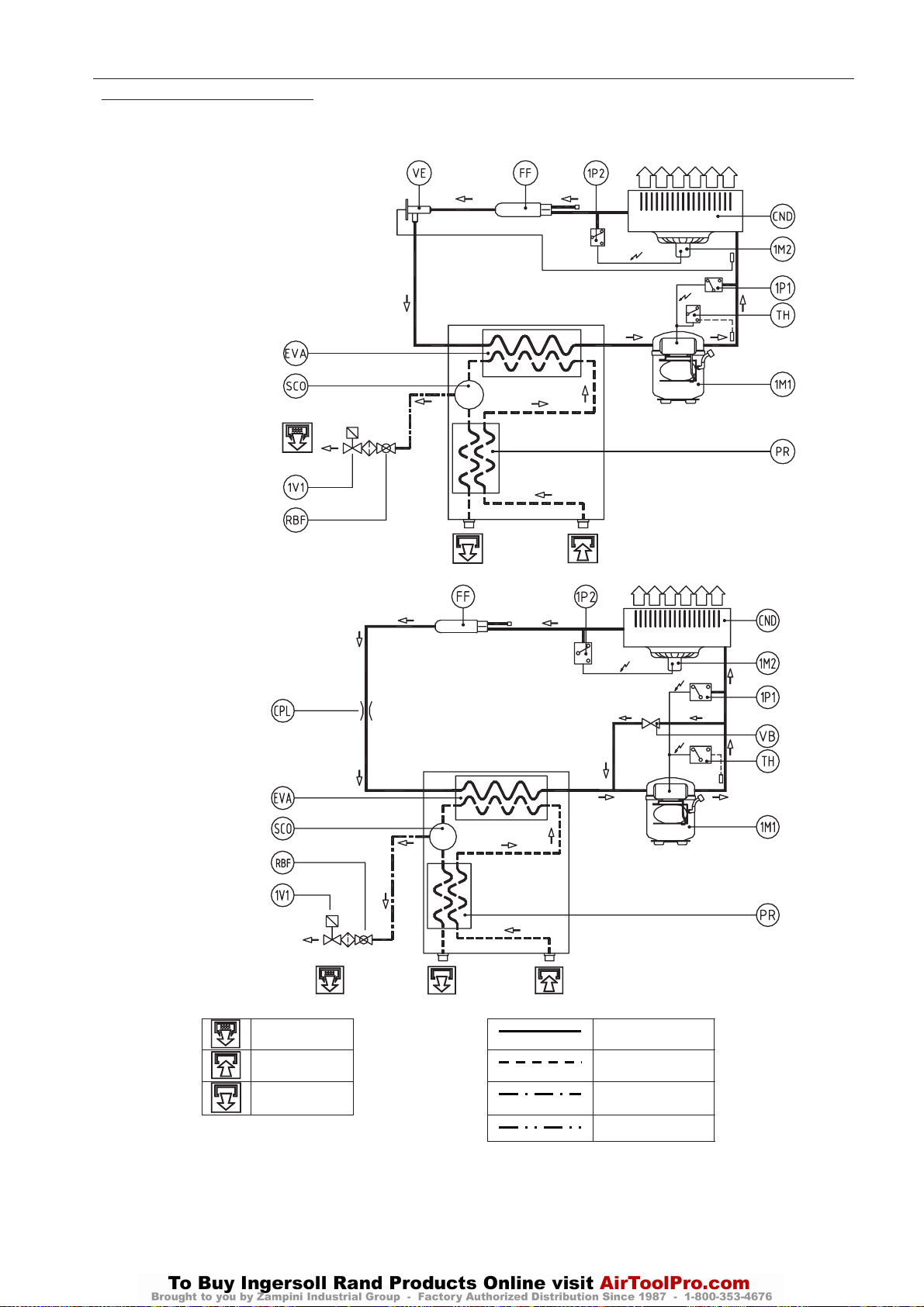
34
UP6 15, UP6 20, UP6 25, UP6 30
http:/air.ingersollrand.com
OPCION DE SECADOR
CIRCUITO DEL REFRIGERANTE
Cód. 713.0007.13.00 – Rev. 00
Modelo UP6 1 5 - 20 HP
UP5 11-15 KW
Cód. 713.0057.07.00 – Rev. 00
Modelo UP6 2 5 - 30 HP
UP5 18-22 KW
Drenaje de
Condensado
Entrada de aire Tubo de aire comprimido
Tubo de refrigerante
Salida de aire
Tubo de drenaje de
condensación
Tubo de ecualización
Page 93
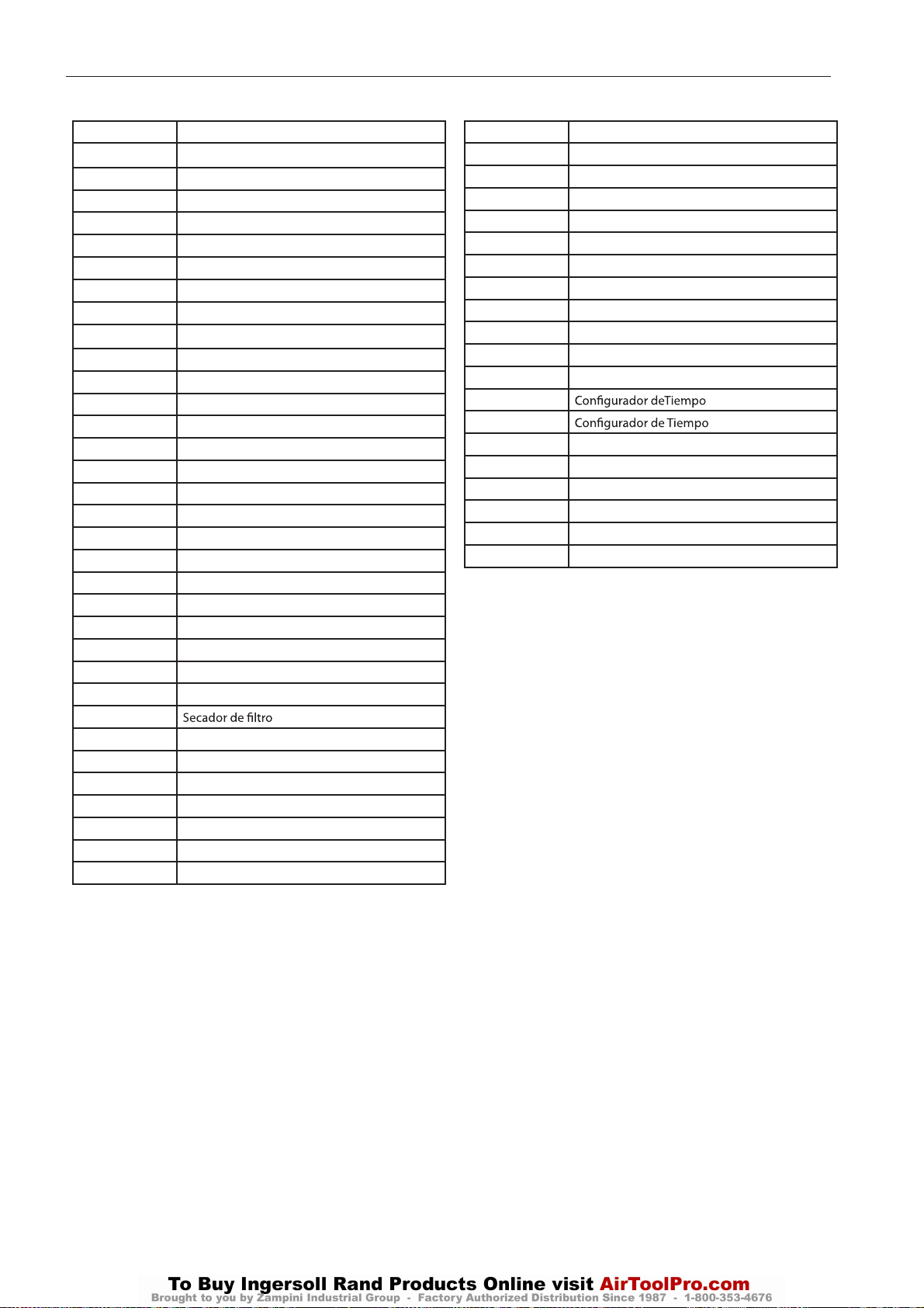
LEYENDA
http:/air.ingersollrand.com
UP6 15, UP6 20, UP6 25, UP6 30
OPCION DE SECADOR
35
Pos. Descripción
1A1 Controlador electrónico
1B1 Bobina de la válvula de solenoide del drenaje
1M1 Compresor del refrigerante
1M2 Motor del ventilador
1P1 Interruptor de presión máxima
1P2 Interruptor de presión del ventilador
1Q1 Interruptor del circuito del compresor
1Q2 Interruptor del circuito del ventilador
1S1 Interruptor de alimentación principal
1S2 Toma
1T1 Transformador
1V1 Válvula de drenaje del solenoide
CB Caja del compresor
CBL CABLES
CND Condensador
CNV Condensador del ventilador
CPL Tubo capilar
EB Caja eléctrica
ED Filtro de 10 micras
EH Filtro de 0,01 micras
EP Filtro de 1 micra
EQ Filtro de 5 micras
EVA Evaporador
F1-F2 Fusibles
FD Filtro de aire de 10 micras
FF
FH Filtro de aire de 0,01 micras
FP Filtro de aire de 1 micra
FQ Filtro de aire de 5 micras
FR Filtro de drenaje
FV Fusible del motor del ventilador
G Parilla
IM Indicador de humedad
K1 Interruptor de contacto
K2 Interruptor de contacto del ventilador
PCP Protección térmica
PR Intercambiador de calor aire-aire
PSC Intercambiador de calor aire-aire (D__IT)
RBF Grifo con colador
RR Reloj Rotalock
RT1 - RT4 Sondas de temperatura
SC Base del intercambiador de calor
SCO Separador de condensación
SLI Separador de líquidos
SSC Drenaje de Condensado
TEMP
TH
TLT Termostato de Control Remoto
VB Válvula de derivación para gas caliente
VE Válvula de expansión
VNR Válvulas de un sentido con colador
VT Pala del ventilador
X1-X2, X3-XM Bloques de terminales
Page 94
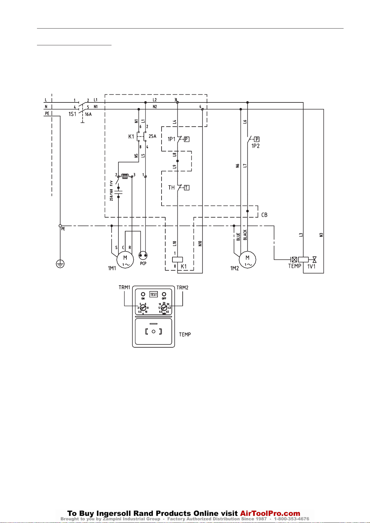
36
UP6 15, UP6 20, UP6 25, UP6 30
http:/air.ingersollrand.com
OPCION DE SECADOR
DIAGRAMA DE CABLEADO
Cód. 714.0172.01.00 – Rev. 00
Modelos UP6 15 – 30 HP (115 V/1 F/60 Hz)
M
TEMP – CONFIGURADOR DE TIEMPO DE
DRENAJE DE CONDENSACIÓN (Vista delantera)
- RECORTADOR 1 (TRM1) – AGUANTE DE DESCARGA (seg.)
- RECORTADOR 2 (TRM2) – INTERVALO ENTRE
DESCARGAS (min.)
Page 95
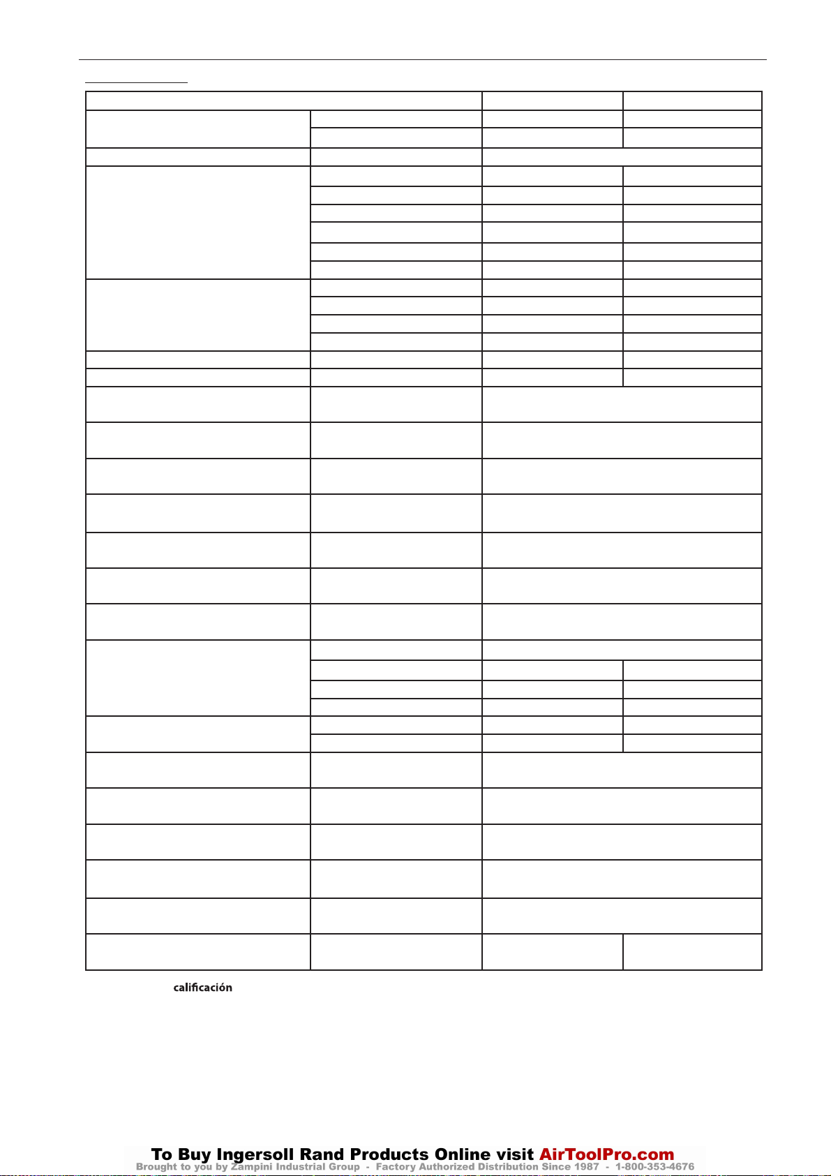
HOJA DE DATOS
http:/air.ingersollrand.com
UP6 15, UP6 20, UP6 25, UP6 30
OPCION DE SECADOR
37
MODELO
RA
VELOCIDAD DEL FLUJO DE AIRE*
FUENTE DE ALIMENTACIÓN VOLT/PH/HZ 115/1/60
1M1
COMPRESOR
1M2
MOTOR DELVENTILADOR
TOTAL A A 9.2 11.3
CONEXIÓN NPT 3/4” 3/4”
T AIRE °F
T MÁX AIRE °F
TAMB °F
T AMB MÍN-MÁX °F
PRES W DEL AIRE psi
PRES. AIRE MÁX psi
PUNTO DE ROCÍO * °F
REF.
REFRIGERANTE
W
PESO
EVAP. TEMP.* °F
TEMP. DE SUCCIÓN .* °F
DESC. PRES.* psig
CONFIGURACIÓN DE INTERRUPTOR DE HP psig
CONFIGURACIÓN DE INTERRUPTOR DEL
VENTILADOR
INTERRUPTOR DEL TERMOSTATO
CONFIGURACIÓN
CFM 83 125
m3/h 140 212
HP 2/3 3/4
kW 0.71 0.83
Max kW 1.14 1.37
RLA 8.16 9.69
FLA 11.6 14
LRA 46 54
QTY 11
HP 1/46 1/20
RLA 1.00 1.60
LRA 1.36 2.10
°C
°C
°C
°C
Bara
Bara
°C
TYPE R134a
LB 0.99 1.65
OZ 15.9 26.46
KG 0.45 0.75
LB 138 147
KG 63 67
°C
°C
Bara
Bara
psig
Bara
°F
°C
UP6 15-20 HP UP6 25-30 HP
212
100
104
40
162
72
77
25
36 – 122
2 – 50
123
8.5
203
14
< 50 (ISO CLASS 6)
< 10 (ISO CLASS 6)
37 – 41
3 – 5
39 – 64
4 – 18
170 - 230
12 – 16
435
30
123 – 160
8,5 – 11
239
115
*Condiciones de de: Entrada de aire a 40º C (104º F) y 123 psig, Temperatura ambiente 25º C (77º F)
*Performances et caractéristiques techniques
Page 96
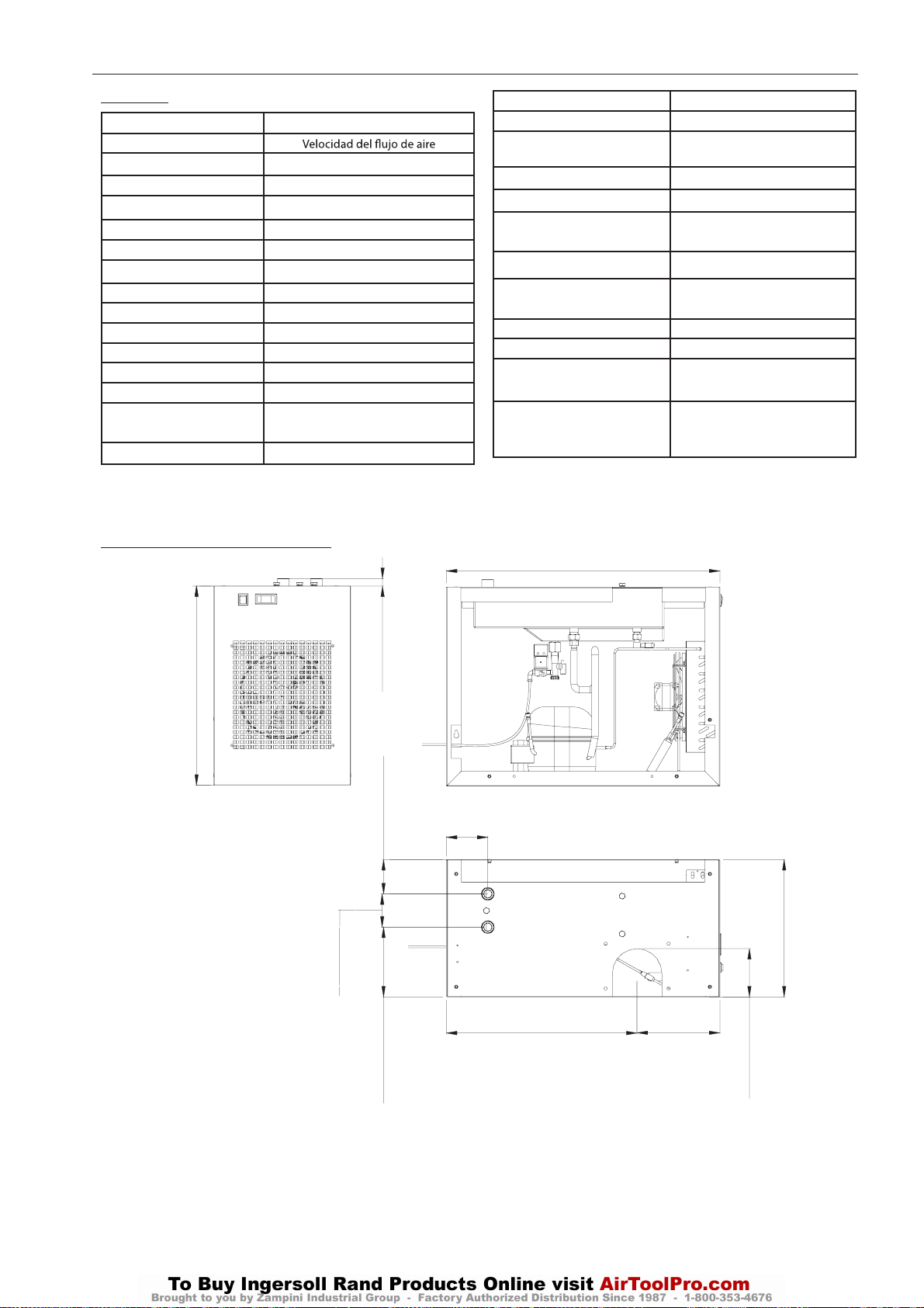
38
UP6 15, UP6 20, UP6 25, UP6 30
http:/air.ingersollrand.com
OPCION DE SECADOR
LEYENDA
POS. DESCRIPCIÓN
AR
FUENTE DE ALIMENTACIÓN Fuente De Alimentación
HP Potencia nominal
kW Consumo nominal
Kw máx Consumo a carga completa
RLA Corriente nominal
FLA Corriente a carga completa
LRA Corriente del motor bloqueado
TOTAL A Corriente total
CONNECTION Conexiones de aire
T AIRE Temperatura de entrada de aire
T MÁX AIRE Temperatura máx. de entrada de aire
T AMB Temperatura ambiente
T AMB MÍN-MÁX Ambiente Mín-Máx
Temperatura
PRES W DEL AIRE Presión máx. del aire
DIMENSIONES DE LA SECADORA
POS. DESCRIPCIÓN
PRES MÁX DEL AIRE Presión máx. del aire
PUNTR Punto de condensación de
presión
REF. Refrigerante
FUSIBLE MÁX Tamaño máximo de fusible
CIRCUITO MÍNIMO
AMPACIDAD
P Peso
EVAP. TEMP. Evaporación
DESC. PRES. Temperatura de succión
DESC. PRES. Presión de descarga
CONF INTERRUPTOR HP Interruptor de presión máxima
INTERRUPTOR DEL
TERMOSTATO
CONFIGURACIÓN
826 (32.52”)
Circuito mínimo
Ampacidad
Temperatura
Interruptor de presión máxima
600 (23.62”)
100 (3.94”)
23 (0.91”)
103 (4.07”)
210 (8.27”)
125 (4.92”)
AIRE ADENTRO
AIRE HACIA FUERA
576 (22.67”)
413 (16.28”)
250 (9.85”)
145 (5.71”)
Page 97
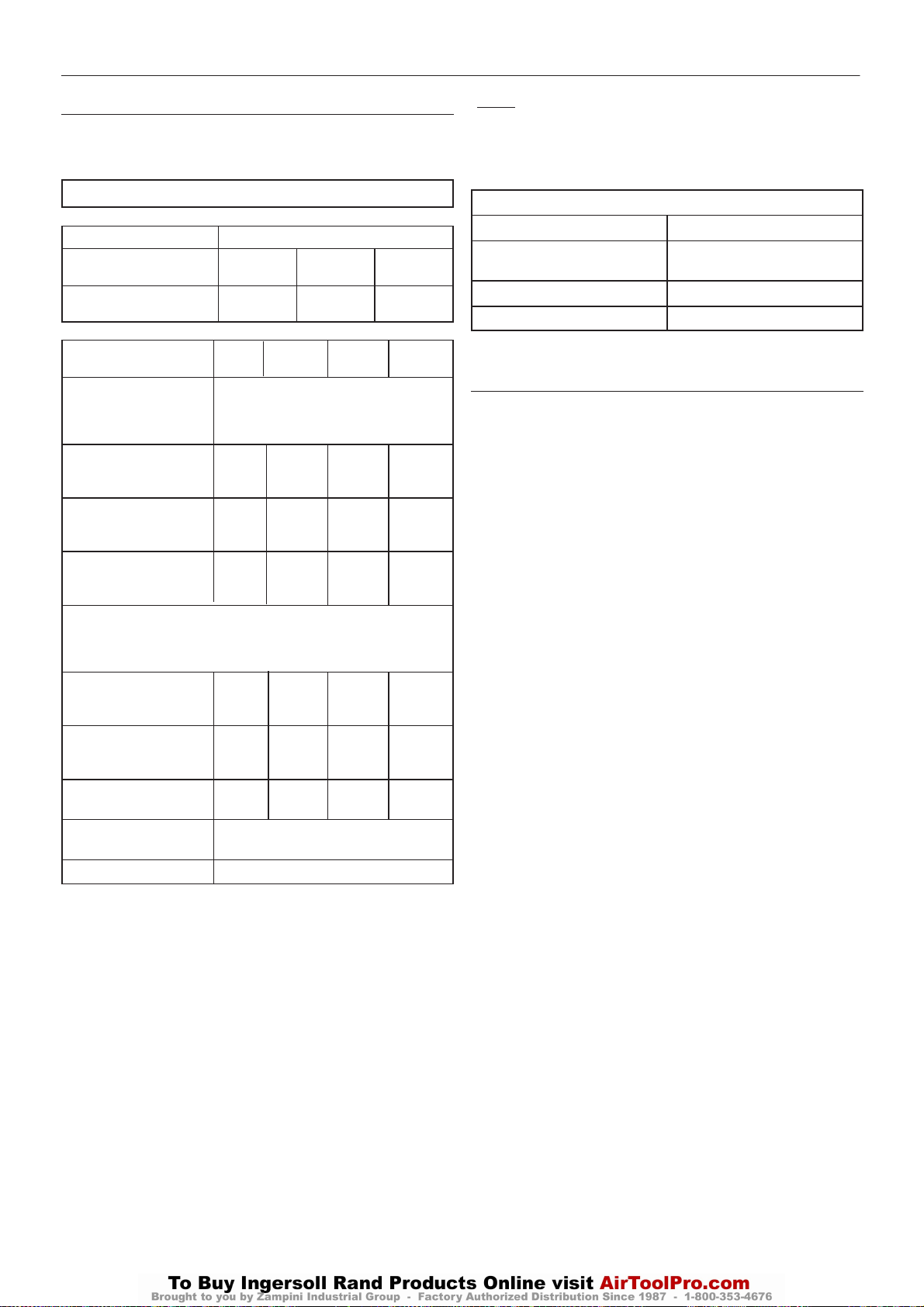
OPCION DE SECADOR
http:/air.ingersollrand.com
UP6 15, UP6 20, UP6 25, UP6 30
39
CALIBRACION
El secador se suministra ajustado de fábrica y, por consiguiente, no
precisa calibración adicional.
DATOS TECNICOS
Compresor
Presión máxima de trabajo
psig (bar)
Presión de recarga fijada
en fábricapsig (bar)
Modelo
Punto de rocío de presión
(oF)
(véase la nota 3 másabajo)
Peso (libras) del paquete
de secador montado
sobre base
Peso (libras) del paquete
de secador de tanque de
120 galones
Peso (libras) del paquete
de secador de tanque de
240 galones
Suministro eléctrico
(+/– 10%) (AC)
(véase la nota 2 más
abajo)
Corriente Rotor
Enclavado (L.R.A.)
(Amperios)
Corriente Rotor
Enclavado (F.R.A.)
(Amperios)
Potencia total instalada
(kW)
Clase de protección
eléctrica (estándar)
Tipo de refrigerante
125
(8.62)
110
(7.58)
UP6 15
1367
1691
1960
45.0
9.6
0.96
UP6 15 - 30
150
(10.34)
135
(9.31)
UP6 20
1411 1451 1537
1735 1775 1861
2004 2044 2130
115V / monofásico / 60Hz
45.0 48.8 48.8
9.6 12.3 12.3
0.96 1.19 1.19
NEMA 1 (IP20)
UP6 25 UP6 30
38
134a
200
(13.79)
185
(12.76)
Notas:
1. Los datos eléctricos se refieren al secador solamente.
2. El secador requiere un suministro eléctrico separado del
accionamientodel compresor.
3. Valores nominales:
Presión de trabajo (psig)
Temperatura del aire de admisión
(oF)
Temperatura ambiente (oF)
Humedad relativa (%)
Notas sobre el uso de la válvula de contraflujoSchrader.
ATENCION
1. Esta unidad está dotada de refrigerante según la cantidad y clase
claramenteindicadas en el manual de funcionamiento y con etiqueta de
identificación.
2. Toda prueba ordinaria y / o recarga de refrigerante por medio de
conexiones, sólo puede realizarse tras la evacuación del refrigerante. La
evacuación deberá ser proporcional a las dimensiones y longitud de las
conexiones utilizadas. El uso de la válvula sólo se puede justificar
cuando el secador no está en condiciones de trabajo. El recipiente de
evacuación deberá tener las dimensiones y longitud apropiada de las
conexiones.
3. Durante el período de garantía de la unidad, la válvula Schrader sólo
puede ser utilizada por personal autorizado, pues de otro modo todo
daño ocasionado por la recarga errónea de refrigerante invalidaría la
garantía.
100
100
100
100
Page 98
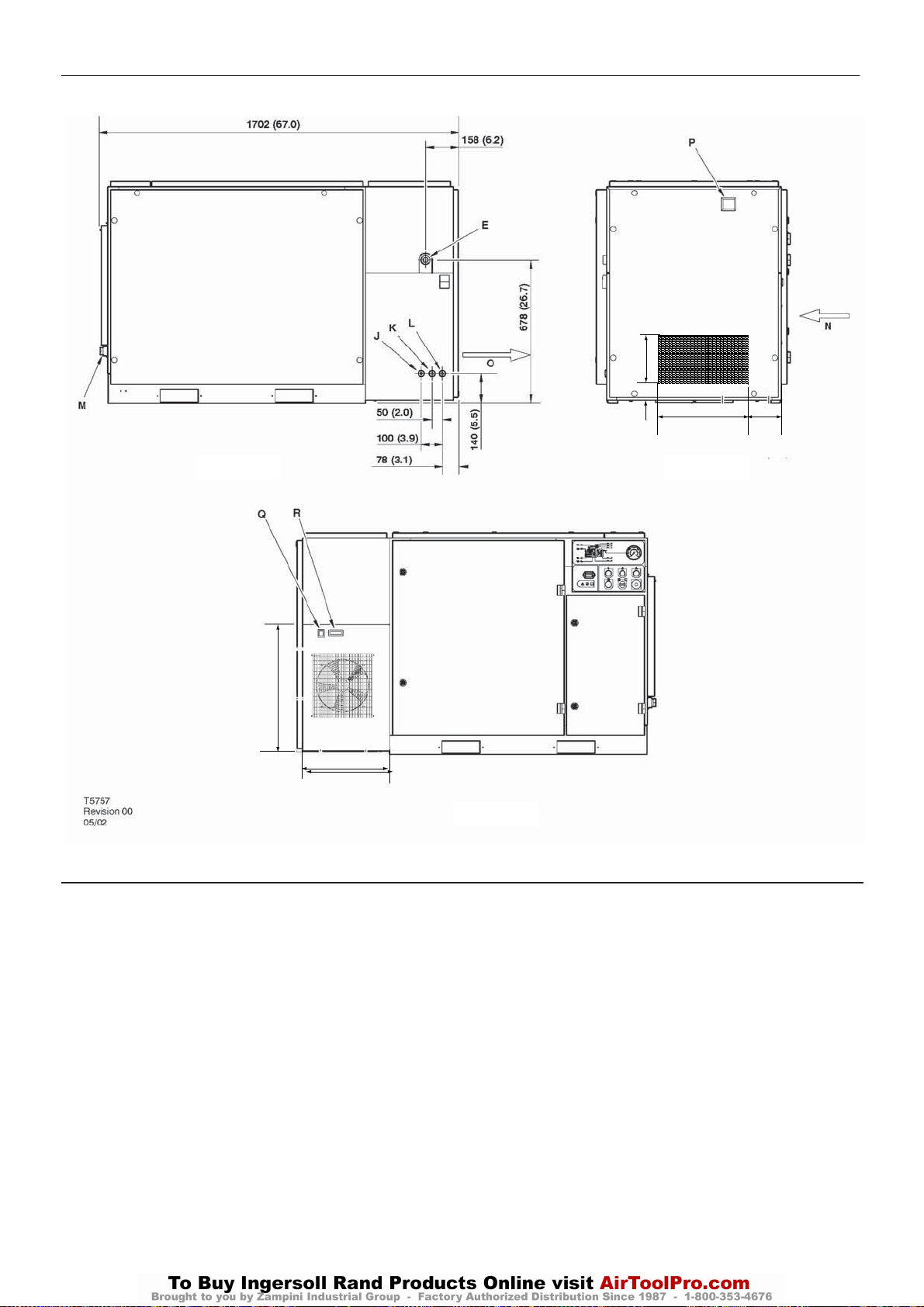
40
UP6 15, UP6 20, UP6 25, UP6 30
http:/air.ingersollrand.com
UNIDADES CON BASE MONTADA
OPCION DE SECADOR
317.3 (12.5)
VISTA POSTERIOR
600
413.5
VISTA FRONTAL
596.3 (23.5)
49
VISTA IZQUIERDA
165
CLAVE
A Filtro previo
B Compresor y admisión del aire refrigerante
C Caja del arranque
D Escape del aire refrigerante
E Descarga de aire de 1,00” BSPT
E Descarga de aire de 1,00” NPT
F Entrada de potencia del cliente
G Aberturas para carretilla elevadora
Deben instalarse cubiertas en los agujeros de la carretilla
elevadora después de que la unidad está en su sitio, para reducir el
ruido y asegurar un enfriamiento adecuado del conjunto.
H Boton parada emergencia
I Puerta de servicio primario del compresor
J Desagüe del separador de humedad de 0,25 pulgadas BSPT
K Desagüe del secador de 0,25 pulgadas BSPT
L Desagüe del filtro de aire de 0,25 pulgadas BSPT
M Tapón de 1,00 pulgada NPT
N Admisión de aire del secador
O Escape de aire del secador
P Indicador de restricciones del filtro
Q Interruptor de apagado/encendido (On/Off) del secador
R Indicador del punto de rocío
Page 99
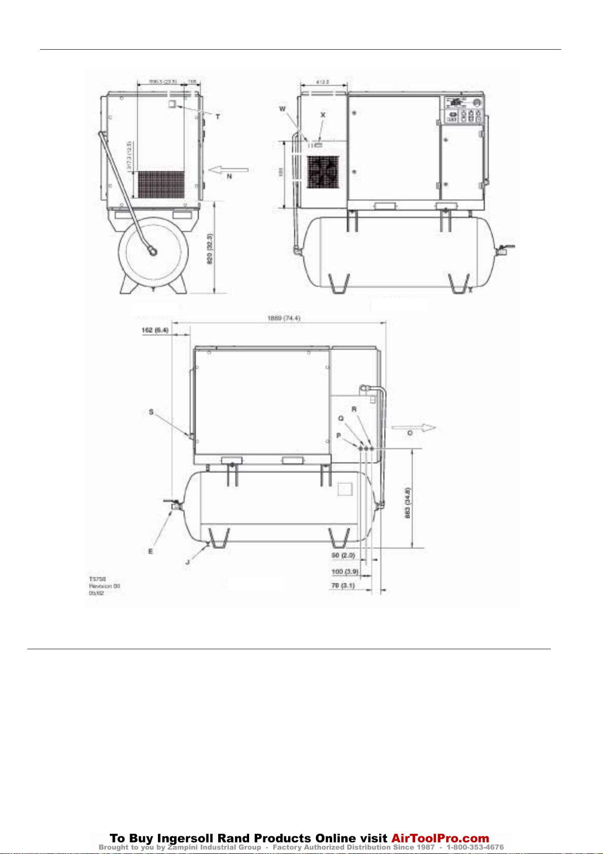
UNIDADES DE 60 Hz (120 GALONES) CON DEPOSITO MONTADO
http:/air.ingersollrand.com
UP6 15, UP6 20, UP6 25, UP6 30
OPCION DE SECADOR
41
VISTA IZQUIERDA
VISTA FRONTAL
VISTA POSTERIOR
CLAVE
A Filtro previo
B Compresor y admisión del aire refrigerante
C Caja del arranque
D Escape del aire refrigerante
E Descarga de aire de 1,00” BSPT
F Entrada de potencia del cliente
G Aberturas para carretilla elevadora
H Recipiente de almacenamiento del aire (120 galones)
I Válvula de desagüe automática
J Válvula de vaciado
K Boton parada emergencia
L Puerta de servicio primario del compresor
M Abertura de inspección
N Admisión de aire del secador
O Escape de aire del secador
P Desagüe del separador de humedad de 0,25 pulgadas BSPT
Q Desagüe del secador de 0,25 pulgadas BSPT
R Desagüe del filtro de aire de 0,25 pulgadas BSPT
S Tapón de 1,00 pulgada NPT
T Indicador de restricciones del filtro
W Interruptor de apagado/encendido (On/Off) del secador
X Indicador del punto de rocío
Page 100
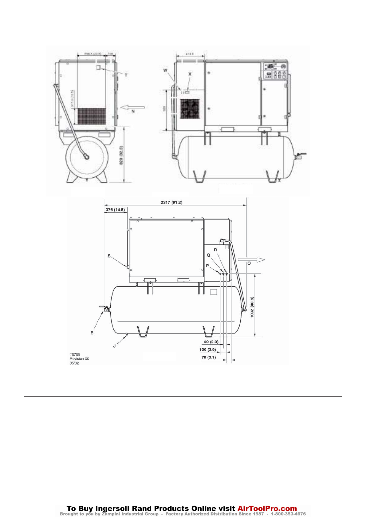
42
UP6 15, UP6 20, UP6 25, UP6 30
http:/air.ingersollrand.com
UNIDADES DE 60 Hz (240 GALONES) CON DEPOSITO MONTADO
OPCION DE SECADOR
VISTA IZQUIERDA
VISTA FRONTAL
VISTA POSTERIOR
CLAVE
A Filtro previo
B Compresor y admisión del aire refrigerante
C Caja del arranque
D Escape del aire refrigerante
E Descarga de aire de 1,00” BSPT
F Entrada de potencia del cliente
G Aberturas para carretilla elevadora
H Recipiente de almacenamiento del aire (240 galones)
I Válvula de desagüe automática
J Válvula de vaciado
K Boton parada emergencia
L Puerta de servicio primario del compresor
M Abertura de inspección
N Admisión de aire del secador
O Escape de aire del secador
P Desagüe del separador de humedad de 0,25 pulgadas BSPT
Q Desagüe del secador de 0,25 pulgadas BSPT
R Desagüe del filtro de aire de 0,25 pulgadas BSPT
S Tapón de 1,00 pulgada NPT
T Indicador de restricciones del filtro
W Interruptor de apagado/encendido (On/Off) del secador
X Indicador del punto de rocío
 Loading...