

Ingersoll-Rand SERIES EL, SERIES EP, SERIES ET Operation And Maintenance Manual

03541299
Form P7213
Edition 5
March, 1999
OPERATION AND MAINTENANCE MANUAL FOR
SERIES EL, EP AND ET 230V AC ELECTRIC SCREWDRIVERS
Series EL, EP and ET Electric Screwdrivers are earthed (grounded) and are designed
for installing threaded fasteners in light industrial and appliance manufacturing
applications.
Ingersoll–Rand is not responsible for customer modification of tools for applications
on which Ingersoll–Rand was not consulted.
IMPORTANT SAFETY INFORMATION ENCLOSED.
READ ALL THESE INSTRUCTIONS BEFORE PLACING TOOL IN SERVICE OR
OPERATING THIS TOOL AND SAVE THESE INSTRUCTIONS.
IT IS THE RESPONSIBILITY OF THE EMPLOYER TO PLACE THE INFORMATION
IN THIS MANUAL INTO THE HANDS OF THE OPERATOR.
FAILURE TO OBSERVE THE FOLLOWING WARNINGS COULD RESULT IN INJURY.
WHEN USING ELECTRIC TOOLS, BASIC SAFETY PRECAUTIONS SHOULD ALWAYS BE
FOLLOWED TO REDUCE THE RISK OF FIRE, ELECTRIC SHOCK AND PERSONAL INJURY,
INCLUDING THE FOLLOWING.
PLACING TOOL IN SERVICE
• Use outdoor extension leads. When tool is used
outdoors, use only extension cords intended for
outdoor use.
• Always operate, inspect and maintain this tool in
accordance with all regulations (local, state, federal
and country), that may apply to hand held/hand
operated electric tools.
• Inspect tool cords periodically and if damaged, have
them repaired by an authorized service facility.
Inspect extension cords periodically and replace if
damaged.
• Do not remove any labels. Replace any damaged
label.
USING THE TOOL
• Do not operate this tool unless the Retainer
Coupling (1) and Flange (2) are installed securely.
• Always wear eye protection when operating or
performing maintenance on this tool.
• Power tools can vibrate in use. Vibration, repetitive
motions, or uncomfortable positions may be
harmful to your hands and arms. Stop using any
tool if discomfort, tingling feeling or pain occurs.
Seek medical advice before resuming use.
• Guard Against Electric Shock. Prevent body contact
with earthed or grounded surfaces. For example;
pipes, radiators, ranges, refrigerator enclosures.
• Don’t abuse Cord. Never carry tool by cord or yank
it to disconnect from receptacle. Keep cord from heat,
oil, and sharp edges.
• Keep work area clean. Cluttered areas and benches
invite injuries.
• Consider work area environment. Don’t expose
power tools and chargers to water. Keep work area
well lighted. Do not use tool in explosive or
flammable atmospheres.
• Keep bystanders and children away. Do not permit
unauthorized personnel to operate this tool, or touch
tool or cord.
• Store idle tools. When not in use, tools should be
stored in a dry, high or locked up place, out of reach of
children.
• Don’t force tool. It will do the job better and more
safely at the rate for which it was intended.
• Use the right tool. Do not force a small tool or
attachment to do the job of a heavy–duty tool.
• Do not use a tool for a purpose for which it is not
intended. Example: Do not use a screwdriver as a
drill.
• Dress properly. Do not wear loose clothing or
jewelry. They can be caught in moving parts. Rubber
gloves and non–skid footwear are recommended when
working outdoors. Wear protective hair covering to
contain long hair.
GB
The use of other than genuine Ingersoll–Rand replacement parts may result in personal injury, decreased tool
performance and increased maintenance, and may invalidate all warranties.
Have your tool repaired by a qualified person. This electric tool is in accordance with the relevant safety requirements.
Repairs should only be carried out by qualified persons using original spare parts, otherwise this may result in
considerable danger to the user.
Repairs should be made only by authorized, trained personnel. Consult your nearest Ingersoll–Rand Authorized
Servicenter.
Ingersoll–Rand Company 1999
Printed in U.S.A.

FAILURE TO OBSERVE THE FOLLOWING WARNINGS COULD RESULT IN INJURY.
USING THE TOOL
(Continued)
• Secure work. Use clamps or a vise to hold work.
Operators often need both hands to perform job
functions.
• Don’t overreach. Keep proper footing, balance, and a
firm grip on the tool at all times.
• Maintain tools with care. Keep tools clean for better
and safer performance. Follow instructions for
lubricating and changing accessories. Inspect tool
cords periodically and if damaged, have them repaired
by an authorized service facility. Inspect extension
cords periodically and replace if damaged. Keep
handles dry, clean, and free from oil and grease.
• Remove adjusting keys and wrenches. Form habit of
checking to see that keys and adjusting wrenches are
removed from tool before turning it on.
• Avoid unintentional starting. Don’t carry tool with
finger on switch.
• Do not drop or abuse the tool.
• Whenever a tool is not being used, position the
Power Switch to the “OFF” position and unplug the
power cord.
• Stay alert. Watch what you are doing. Use common
sense. Do not operate tool when you are tired.
• Check damaged parts. Before further use of the tool,
a guard or other part that is damaged should be
carefully checked to determine that it will operate
properly and perform its intended function. Check for
alignment of moving parts, binding of moving parts,
breakage of parts, mounting, and any other conditions
that may affect its operation. A guard or other part that
is damaged should be properly repaired or replaced by
an authorized service center unless otherwise indicated
elsewhere in this operation manual.
• Have defective switches replaced by an authorized
service center.
• Do not use the tool if the switch does not turn it on
and off.
• Do not drop or abuse the screwdriver.
• Whenever changing a bit, make certain the
Forward/Reverse Switch is in the “OFF” position
and the tool is unplugged.
• Do not allow chemicals such as acetone, benzene,
thinner, ketone, trichloroethylene or other similar
chemicals to come in contact with the screwdriver
housing as damage will result.
• Do not adjust the torque setting higher than 5 on
the Torque Scale.
Duty cycle:
MAX 0.8 sec. “ON”
MIN 3.2 sec. “OFF”
• Do not tighten more than 900 tapping screws
(size: 2 mm, length: 4 mm) per hour.
• Do not operate the Forward/Reverse Switch when
the motor is running.
• Whenever a tool is not being used, move the
Forward/Reverse Switch to the “OFF” position and
unplug the screwdriver.
• The use of any accessory or attachment other than
recommended in this manual can present a risk of
personal injury.
WARNING LABEL IDENTIFICATION
WARNING
Always wear eye protection
when operating or performing maintenance on this
tool.
WARNING
Powered tools can vibrate in
use. Vibration, repetitive motions or uncomfortable positions may be harmful to your
hands and arms. Stop using
any tool if discomfort, tingling
feeling or pain occurs. Seek
medical advice before resuming use.
WARNING
Always wear hearing
protection when operating
this tool.
WARNING
Do not carry the tool by
the cord.
WARNING
Keep body stance balanced
and firm. Do not overreach
when operating this tool.
2
WARNING
Always turn off the electrical
supply and disconnect the
power cord before installing,
removing or adjusting any
accessory on this tool, or
before performing any
maintenance on this tool.
WARNING
Do not use damaged, frayed
or deteriorated power cords.

ADJUSTMENTS
TORQUE ADJUSTMENT
To adjust the torque on these screwdrivers, proceed as
follows:
1. Determine the torque output of the tool by checking a
tightened fastener with a torque wrench.
2. Increase or decrease the torque output by rotating the
Spring Adjusting Ring (4). Rotating the Ring
clockwise to a higher number on the Torque Scale
increases torque output while rotating the Ring
counterclockwise to a lower number decreases the
torque output.
The numbers from one to five on the Torque Scale
are reference numbers only and are not an
indication of actual torque output.
SAVE THESE INSTRUCTIONS. DO NOT DESTROY.
3. Check the adjustment with a torque wrench. A number
of factors will affect torque output from one job to
another. Final torque adjustment should be made at the
job through a series of gradual increases. Always start
below the desired torque and work upward.
DO NOT ATTEMPT TO
REPAIR THIS TOOL.
All repairs and maintenance of this tool and its
cord must be performed by an authorized
service center. Contact Sales Office listed on last
page of this form.
MODEL IDENTIFICATION
(Dwg. TPD1823)
3

MAINTENANCE SECTION
4
Model Hertz Watts Volts Revolutions
per minute
Type
of
cord
Torque
Range
in–lbs
Torque
Range
Kgf–cm
Weight
lbs. Kg.
Length
in. mm
Drive Size
in.
Sound
Pressure
Level
dB (A)
♦Vibrations
Level
m/s
2
STRAIGHT SCREWDRIVERS
EL1510E–E 50/60 Hz 30W
230 V ~
1000 min–1VDE 5.0 – 15.0 5.8 – 17.3 1.6 0.73 10.8 274 1/4 hex 70.7 1.1
EL1510E–U 50/60 Hz 30W
230 V ~
1000 min
–1
UK 5.0 – 15.0 5.8 – 17.3 1.6 0.73 10.8 274 1/4 hex 70.7 1.1
EL2607E–E 50/60 Hz 30W
230 V ~
700 min–1VDE 11.0 – 26.0 12.7 – 30.0 1.6 0.73 10.8 274 1/4 hex 61.7 1.0
EL2607E–U 50/60 Hz 30W
230 V ~
700 min
–1
UK 11.0 – 26.0 12.7 – 30.0 1.6 0.73 10.8 274 1/4 hex 61.7 1.0
ET4004E–E 50/60 Hz 30W
230 V ~
400 min–1VDE 18.0 – 40.0 20.7 – 46.0 1.6 0.73 10.8 274 1/4 hex 70.7 1.1
ET4004E–U 50/60 Hz 30W
230 V ~
400 min
–1
UK 18.0 – 40.0 20.7 – 46.0 1.6 0.73 10.8 274 1/4 hex 70.7 1.1
EP1510E–E 50/60 Hz 30W
230 V ~
1000 min–1VDE 5.0 – 15.0 5.8 – 17.3 1.6 0.73 10.8 274 1/4 hex 70.7 1.1
EP1510E–U 50/60 Hz 30W
230 V ~
1000 min
–1
UK 5.0 – 15.0 5.8 – 17.3 1.6 0.73 10.8 274 1/4 hex 70.7 1.1
EP2607E–E 50/60 Hz 30W
230 V ~
700 min–1VDE 11.0 – 26.0 12.7 – 30.0 1.6 0.73 10.8 274 1/4 hex 61.7 1.0
EP2607E–U 50/60 Hz 30W
230 V ~
700 min
–1
UK 11.0 – 26.0 12.7 – 30.0 1.6 0.73 10.8 274 1/4 hex 61.7 1.0
EP4004E–E 50/60 Hz 30W
230 V ~
400 min–1VDE 18.0 – 40.0 20.7 – 46.0 1.83 0.83 10.8 274 1/4 hex 70.7 1.1
EP4004E–U 50/60 Hz 30W
230 V ~
400 min
–1
UK 18.0 – 40.0 20.7 – 46.0 1.83 0.83 10.8 274 1/4 hex 70.7 1.1
ANGLE SCREWDRIVERS, ANGLE WRENCHES
EL1510E1S5–E 50/60 Hz 30W
230 V ~
950 min–1VDE 4.0 – 17.0 4.6 – 19.6 2.0 0.91 17.5 444 1/4 square 70.7 1.1
EL1510E1S5–U 50/60 Hz 30W
230 V ~
950 min
–1
UK 4.0 – 17.0 4.6 – 19.6 2.0 0.91 17.5 444 1/4 square 70.7 1.1
EL1510E2S3–E 50/60 Hz 30W
230 V ~
650 min–1VDE 6.0 – 23.0 6.9 – 26.5 2.2 1.00 17.6 447 1/4 hex 70.7 1.1
EL1510E2S3–U 50/60 Hz 30W
230 V ~
650 min
–1
UK 6.0 – 23.0 6.9 – 26.5 2.2 1.00 17.6 447 1/4 hex 70.7 1.1
EL1510E2S5–E 50/60 Hz 30W
230 V ~
650 min–1VDE 6.0 – 23.0 6.9 – 26.5 2.2 1.00 17.6 447 1/4 square 70.7 1.1
EL1510E2S5–U 50/60 Hz 30W
230 V ~
650 min
–1
UK 6.0 – 23.0 6.9 – 26.5 2.2 1.00 17.6 447 1/4 square 70.7 1.1
ET4004E2S3–E 50/60 Hz 30W
230 V ~
260 min–1VDE 15.0 – 56.0 17.3 – 64.5 2.2 1.00 17.6 447 1/4 hex 70.7 1.1
ET4004E2S3–U 50/60 Hz 30W
230 V ~
260 min
–1
UK 15.0 – 56.0 17.3 – 64.5 2.2 1.00 17.6 447 1/4 hex 70.7 1.1
ET4004E2S5–E 50/60 Hz 30W
230 V ~
260 min–1VDE 15.0 – 56.0 17.3 – 64.5 2.2 1.00 17.6 447 1/4 square 70.7 1.1
ET4004E2S5–U 50/60 Hz 30W
230 V ~
260 min
–1
UK 15.0 – 56.0 17.3 – 64.5 2.2 1.00 17.6 447 1/4 square 70.7 1.1
Tested in accordance with ANSI S5.1–1971 at free speed.
♦ Tested in accordance to ISO8662–1 at free speed.

DECLARATION OF CONFORMITY
We
Ingersoll–Rand, Co.
(supplier’s name)
Swan Lane, Hindley Green, Wigan WN2 4EZ
(address)
declare under our sole responsibility that the product,
Series EL, EP and ET 230V AC Electric Screwdrivers
to which this declaration relates, is in compliance with the provisions of
89/336/EEC, 73/23/EEC,
92/31/EEC AND 93/37/EC
EN292, ISO8662, PN8NTC1.2,
By using the following Principle Standards:
Serial No. Range:
(1995 → ) 3VH XXXXX →
EN50144–1, EN50082–1 and EN55014
Directives.
D. Vose James Wardlaw
Name and signature of authorised persons Name and signature of authorised persons
March, 1999
Date Date
SAVE THESE INSTRUCTIONS. DO NOT DESTROY.
When the life of the tool has expired, it is recommended that the tool be disassembled,
degreased and parts be separated by material so that they can be recycled.
March, 1999
5

MAINTENANCE SECTION
Dimensions for Series EL/EP/ET Electric Screwdrivers
TYPICAL FOR:
(Dwg. TPC630)
EL1510E
EL2607E
ET4004E
DIMENSION DRAWING
6
TYPICAL FOR:
EP1510E
EP2607E
EP4004E
(Dwg. TPC629)

MAINTENANCE SECTION
Dimension for Series EL/EP/ET Electric Screwdrivers
Handle for Series EL/EP/ET Electric Screwdrivers
‘
(Dwg. TPC631)
(Dwg. TPD1829)
7
MAINTENANCE SECTION
8
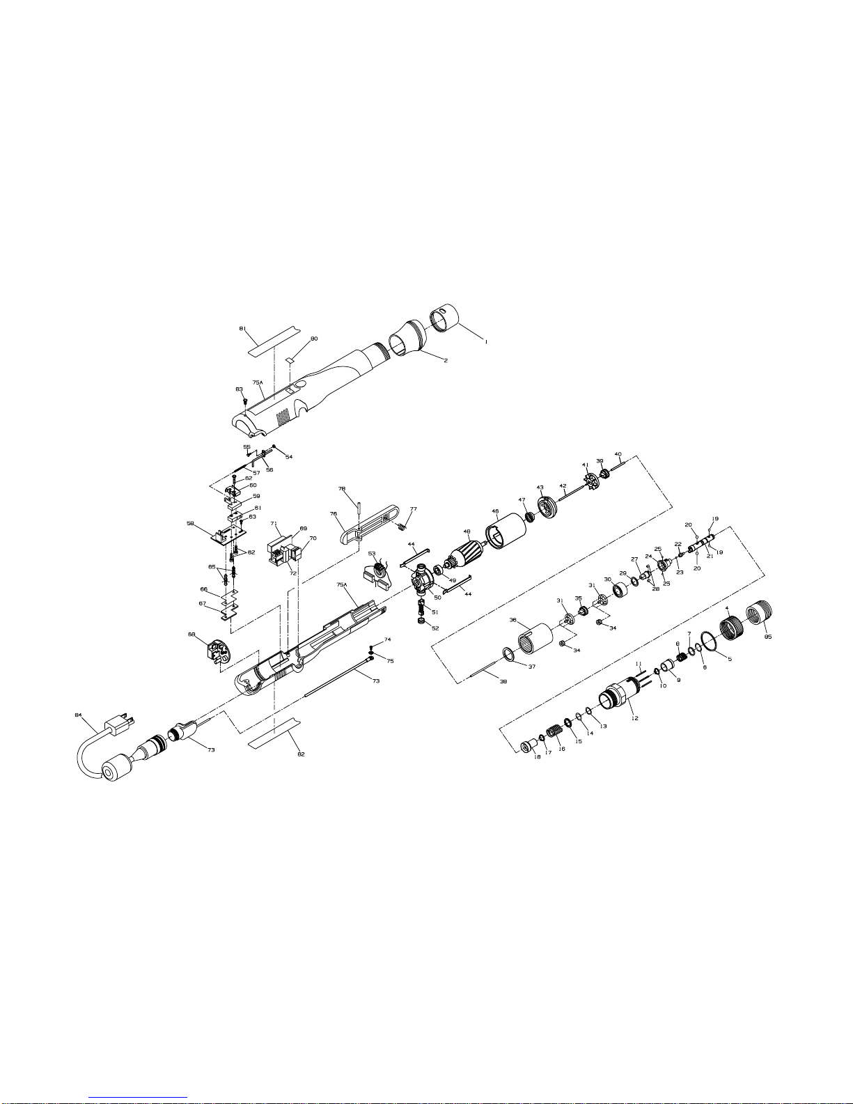
(Dwg. TPA1519–2)
Models EL1510E, EL2607E and ET4004E Electric Screwdrivers

MAINTENANCE SECTION
9
Models EL1510E, EL2607E and ET4004E Electric Screwdrivers
PART NUMBER FOR ORDERING PART NUMBER FOR ORDERING
1 Retainer Coupling . . . . . . . . . . . . . . . . . . . . . . . . . . . . EP4007N–125 25 Cam Guide Ball (.156 dia.) . . . . . . . . . . . . . . . . . . . . 2U–696
2 Slanted Flange (Standard on 1510E and 2607E) . . . . EP4007N–124 27 Cam
* Straight Flange (Standard on 4004E) . . . . . . . . . . . . EP4007N–123 for ET4004E . . . . . . . . . . . . . . . . . . . . . . . . . EP4007N–581
4 Clutch Adjusting Ring . . . . . . . . . . . . . . . . . . . . . . . . EP4007N–582 for all others . . . . . . . . . . . . . . . . . . . . . . . . . EP1510N–581
5 Indicator Ring . . . . . . . . . . . . . . . . . . . . . . . . . . . . . . . EP4007N–682 28 Cam Roller (2) . . . . . . . . . . . . . . . . . . . . . . . . . . . . . . EP4007N–587
6 Bit Retainer Retaining Ring (Front) (for models 29 Spindle Washer . . . . . . . . . . . . . . . . . . . . . . . . . . . . . . EP4007N–509
ending in E only) . . . . . . . . . . . . . . . . . . . . . . . . . . . . EP4007N–683 30 Spindle Bearing . . . . . . . . . . . . . . . . . . . . . . . . . . . . . EP4007N–510
7 Bit Retainer Collar (for models ending in E only) . . . EP4007N–585 31 Spindle/Gear Head (2) . . . . . . . . . . . . . . . . . . . . . . . . EP2607N–216
8 Bit Retainer Spring (for models ending in E only) . . EP4007N–931 34 Planet Gear
9 Bit Retainer Sleeve (for models ending in E only) . . EP4007N–930 for EL1510E (6) . . . . . . . . . . . . . . . . . . . . . . EP1510N–10
10 Bit Retainer Retaining Ring . . . . . . . . . . . . . . . . . . . . EP4007N–584 for ET4004E (6) . . . . . . . . . . . . . . . . . . . . . . EP1520N–10
11 Clutch Adjusting Pin (3) . . . . . . . . . . . . . . . . . . . . . . . EP4007N–416 for EL2607E (6) . . . . . . . . . . . . . . . . . . . . . . EP2607N–10
12 Clutch Housing Assembly 35 Gear Head Pinion Gear
for models ending in 1S5, 2S3 or 2S5 . . . . . ET4007N2S5–580 for EL1510E . . . . . . . . . . . . . . . . . . . . . . . . EP1510N–17
for all other models . . . . . . . . . . . . . . . . . . . . EP4007N–580 for ET4004E . . . . . . . . . . . . . . . . . . . . . . . . . EP2603N–17
13 Front Shim . . . . . . . . . . . . . . . . . . . . . . . . . . . . . . . . . EL4007N–623 for EL2607E . . . . . . . . . . . . . . . . . . . . . . . . . EP2607N–17
14 Rear Shim . . . . . . . . . . . . . . . . . . . . . . . . . . . . . . . . . . EL4007N–624 36 Gear Case
15 Clutch Spring Plate . . . . . . . . . . . . . . . . . . . . . . . . . . . EP4007N–623 for EL1510E . . . . . . . . . . . . . . . . . . . . . . . . . EP1510N–37
16 Clutch Spring for ET4004E . . . . . . . . . . . . . . . . . . . . . . . . . EP4007N–37
for EL1510E . . . . . . . . . . . . . . . . . . . . . . . . . EP1510N–583 for EL2607E . . . . . . . . . . . . . . . . . . . . . . . . . EP2607N–37
for EL2607E . . . . . . . . . . . . . . . . . . . . . . . . . EP2607N–583 37 Gear Case Shield . . . . . . . . . . . . . . . . . . . . . . . . . . . . EP4007N–207
for ET4004E . . . . . . . . . . . . . . . . . . . . . . . . . EP4007N–583 38 Clutch Pilot Rod “I” (2.26” long) . . . . . . . . . . . . . . . . EP4007N–435
17 Taper Ring Retaining Ring . . . . . . . . . . . . . . . . . . . . . EP4007N–584
18 Taper Ring Assembly
for EL2607E, EL1510E and ET4004E . . . . . EP2607N–588
19 Bit Retaining Ball (.094” dia.) (2) (for models
ending in N only) . . . . . . . . . . . . . . . . . . . . . . . . . . . . R000B–263
20 Pilot Cam Ball (.156 dia.) (4) . . . . . . . . . . . . . . . . . . . 2U–696
21 Bit Holder Assembly . . . . . . . . . . . . . . . . . . . . . . . . . EP4007N–586
22 Pilot . . . . . . . . . . . . . . . . . . . . . . . . . . . . . . . . . . . . . . . EP4007N–408
23 Pilot Ball (.062 dia.) . . . . . . . . . . . . . . . . . . . . . . . . . . EP4007N–422
24 Cam Guide . . . . . . . . . . . . . . . . . . . . . . . . . . . . . . . . . EP4007N–681
* Not Illustrated
 Loading...