

Ingersoll-Rand S9V2C080U5PSBA, S9V2B080U3PSBA, S9V2B040U3PSBA, S9V2B060U4PSBA, S9V2C100U4PSBA Installer's Manual
...Page 1
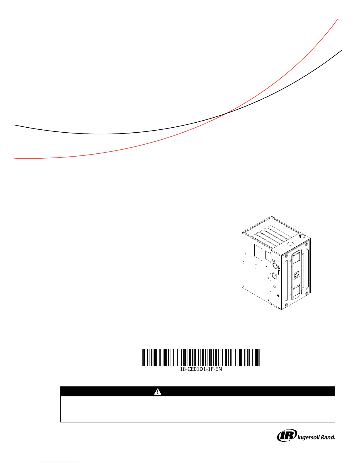
Installer’s Guide
Upflow/Horizontal and Downflow
Gas-Fired, Direct/Non-Direct Vent, 2–Stage
Condensing Variable Speed Furnaces
UUppffllooww,, CCoonnvveerrttiibbllee ttoo
HHoorriizzoonnttaall RRiigghhtt oorr
HHoorriizzoonnttaall LLeefftt
S9V2B040U3PSBA
S9V2B060U3PSBA
S9V2B060U4PSBA
S9V2B080U3PSBA
S9V2B080U4PSBA
S9V2C080U5PSBA
S9V2C100U4PSBA
S9V2C100U5PSBA
S9V2D120U5PSBA
DDoowwnnffllooww OOnnllyy
S9V2B040D3PSBA
S9V2B060D3PSBA
S9V2B080D3PSBA
S9V2B080D4PSBA
S9V2C100D4PSBA
S9V2C100D5PSBA
S9V2D120D5PSBA
NNoottee:: Graphics in this document are for representation
only. Actual model may differ in appearance.
D345855P01
Only qualified personnel should install and service the equipment. The installation, starting up, and servicing of heating, ventilating, and
air-conditioning equipment can be hazardous and requires specific knowledge and training. Improperly installed, adjusted or altered
equipment by an unqualified person could result in death or serious injury. When working on the equipment, observe all precautions in the
literature and on the tags, stickers, and labels that are attached to the equipment.
February 2017
SSAAFFEETTYY WWAARRNNIINNGG
1188--CCEE0011DD11--11FF--EENN
Page 2
SAFETY SECTION— FURNACES
IInnggeerrssoollll RRaanndd hhaass aa ppoolliiccyy ooff ccoonnttiinnuuoouuss pprroodduucctt
aanndd pprroodduucctt ddaattaa iimmpprroovveemmeenntt aanndd iitt rreesseerrvveess tthhee
rriigghhtt ttoo cchhaannggee ddeessiiggnn aanndd ssppeecciiffiiccaattiioonnss wwiitthhoouutt
nnoottiiccee..
IImmppoorrttaanntt:: — This document pack contains a wiring
diagram and service information. This is
customer property and is to remain with
this unit. Please return to service
information pack upon completion of work.
WWAARRNNIINNGG
FFIIRREE OORR EEXXPPLLOOSSIIOONN HHAAZZAARRDD!!
Failure to follow safety warnings exactly
could result in a fire or explosion causing
property damage, personal injury or loss
of life.
—— DDoo nnoott ssttoorree oorr uussee ggaassoolliinnee oorr ootthheerr
ffllaammmmaabbllee vvaappoorrss aanndd lliiqquuiiddss iinn tthhee vviicciinniittyy ooff
tthhiiss oorr aannyy ootthheerr aapppplliiaannccee.. —— WWHHAATT TTOO DDOO IIFF
YYOOUU SSMMEELLLL GGAASS
•• DDoo nnoott ttrryy ttoo lliigghhtt aannyy aapppplliiaannccee..
•• DDoo nnoott ttoouucchh aannyy eelleeccttrriiccaall sswwiittcchh;;ddoo nnoott uussee
aannyy pphhoonnee iinn yyoouurr bbuuiillddiinngg..
•• IImmmmeeddiiaatteellyy ccaallll yyoouurr ggaass ssuupppplliieerr ffrroomm aa
nneeiigghhbboorr’’ss pphhoonnee.. FFoollllooww tthhee ggaass ssuupppplliieerr''ss
iinnssttrruuccttiioonnss..
•• IIff yyoouu ccaannnnoott rreeaacchh yyoouurr ggaass ssuupppplliieerr,, ccaallll
tthhee ffiirree ddeeppaarrttmmeenntt..
—— IInnssttaallllaattiioonn aanndd sseerrvviiccee mmuusstt bbee ppeerrffoorrmmeedd
bbyy aa qquuaalliiffiieedd iinnssttaalllleerr,, sseerrvviiccee aaggeennccyy,, oorr tthhee
ggaass ssuupppplliieerr..
WWAARRNNIINNGG
EEXXPPLLOOSSIIOONN HHAAZZAARRDD!!
FFaaiilluurree ttoo ffoollllooww tthhiiss wwaarrnniinngg ccoouulldd rreessuulltt iinn
pprrooppeerrttyy ddaammaaggee,, ppeerrssoonnaall iinnjjuurryy oorr ddeeaatthh..
IInnssttaallll aa ggaass ddeetteeccttiinngg wwaarrnniinngg ddeevviiccee iinn ccaassee ooff aa
ggaass lleeaakk.. NNOOTTEE:: TThhee mmaannuuffaaccttuurreerr ooff yyoouurr ffuurrnnaaccee
ddooeess nnoott tteesstt aannyy ddeetteeccttoorrss aanndd mmaakkeess nnoo
rreepprreesseennttaattiioonnss rreeggaarrddiinngg aannyy bbrraanndd oorr ttyyppee ooff
ddeetteeccttoorr..
WWAARRNNIINNGG
EEXXPPLLOOSSIIOONN HHAAZZAARRDD!!
FFaaiilluurree ttoo ffoollllooww tthhiiss wwaarrnniinngg ccoouulldd rreessuulltt iinn
pprrooppeerrttyy ddaammaaggee,, ppeerrssoonnaall iinnjjuurryy oorr ddeeaatthh..
NNeevveerr uussee aann ooppeenn ffllaammee ttoo ddeetteecctt ggaass lleeaakkss..
EExxpplloossiivvee ccoonnddiittiioonnss mmaayy ooccccuurr.. UUssee aa lleeaakk tteesstt
ssoolluuttiioonn oorr ootthheerr aapppprroovveedd mmeetthhooddss ffoorr lleeaakk
tteessttiinngg..
WWAARRNNIINNGG
EELLEECCTTRRIICCAALL SSHHOOCCKK,, FFIIRREE,, OORR
EEXXPPLLOOSSIIOONN HHAAZZAARRDD!!
FFaaiilluurree ttoo ffoollllooww tthhiiss WWaarrnniinngg ccoouulldd rreessuulltt iinn
ddaannggeerroouuss ooppeerraattiioonn,, pprrooppeerrttyy ddaammaaggee,, sseevveerree
ppeerrssoonnaall iinnjjuurryy,, oorr ddeeaatthh..
IImmpprrooppeerr sseerrvviicciinngg ccoouulldd rreessuulltt iinn ddaannggeerroouuss
ooppeerraattiioonn,, pprrooppeerrttyy ddaammaaggee,, sseevveerree ppeerrssoonnaall
iinnjjuurryy,, oorr ddeeaatthh..
•• BBeeffoorree sseerrvviicciinngg,, ddiissccoonnnneecctt aallll eelleeccttrriiccaall
ppoowweerr ttoo ffuurrnnaaccee..
•• WWhheenn sseerrvviicciinngg ccoonnttrroollss,, llaabbeell aallll wwiirreess pprriioorr
ttoo ddiissccoonnnneeccttiioonn.. RReeccoonnnneecctt wwiirreess ccoorrrreeccttllyy..
•• VVeerriiffyy pprrooppeerr ooppeerraattiioonn aafftteerr sseerrvviicciinngg..
WWAARRNNIINNGG
CCAARRBBOONN MMOONNOOXXIIDDEE PPOOIISSOONNIINNGG
HHAAZZAARRDD!!
FFaaiilluurree ttoo ffoollllooww tthhiiss WWaarrnniinngg ccoouulldd rreessuulltt iinn
pprrooppeerrttyy ddaammaaggee,, sseevveerree ppeerrssoonnaall iinnjjuurryy,, oorr
ddeeaatthh..
TToo eennssuurree ffuurrnnaaccee iiss vveenntteedd pprrooppeerrllyy,, ddoo nnoott
rreeppllaaccee ffaaccttoorryy ssuupppplliieedd vveennttiinngg ccoommppoonneennttss wwiitthh
ffiieelldd ffaabbrriiccaatteedd ppaarrttss.. FFaabbrriiccaattiinngg ppaarrttss ccaann rreessuulltt
iinn ddaammaaggeedd vveennttss aanndd ccoommppoonneennttss aalllloowwiinngg
ccaarrbboonn mmoonnooxxiiddee ttoo eessccaappee tthhee vveennttiinngg ssyysstteemm..
WWAARRNNIINNGG
CCAARRBBOONN MMOONNOOXXIIDDEE HHAAZZAARRDD!!
FFaaiilluurree ttoo ffoollllooww tthhiiss WWaarrnniinngg ccoouulldd rreessuulltt iinn
pprrooppeerrttyy ddaammaaggee,, sseevveerree ppeerrssoonnaall iinnjjuurryy,, oorr
ddeeaatthh..
DDoo nnoott aatttteemmpptt ttoo cchhaannggee tthhee vveennttiinngg ssyysstteemm..
FFoollllooww tthhee iinnssttaallllaattiioonn aanndd ooppeerraattiioonn iinnssttrruuccttiioonnss
ffoorr tthhee vveennttiinngg ssyysstteemm..
©2017 Ingersoll Rand All rights reserved
18-CE01D1-1F-EN
Page 3
SSAAFFEETTYY SSEECCTTIIOONN—— FFUURRNNAACCEESS
WWAARRNNIINNGG
FFIIRREE HHAAZZAARRDD!!
FFaaiilluurree ttoo ffoollllooww tthhiiss WWaarrnniinngg ccoouulldd rreessuulltt iinn
pprrooppeerrttyy ddaammaaggee,, sseevveerree ppeerrssoonnaall iinnjjuurryy,, oorr
ddeeaatthh..
DDoo nnoott iinnssttaallll tthhee ffuurrnnaaccee ddiirreeccttllyy oonn ccaarrppeettiinngg,, ttiillee
oorr ootthheerr ccoommbbuussttiibbllee mmaatteerriiaall ootthheerr tthhaann wwoooodd
fflloooorriinngg.. FFoorr vveerrttiiccaall ddoowwnnffllooww aapppplliiccaattiioonnss,,
ssuubbbbaassee ((bbaayybbaassee220055)) mmuusstt bbee uusseedd bbeettwweeeenn tthhee
ffuurrnnaaccee aanndd ccoommbbuussttiibbllee fflloooorriinngg.. WWhheenn tthhee
ddoowwnnffllooww ffuurrnnaaccee iiss iinnssttaalllleedd vveerrttiiccaallllyy wwiitthh aa
ccaasseedd ccooiill,, aa ssuubbbbaassee iiss nnoott rreeqquuiirreedd..
WWAARRNNIINNGG
HHAAZZAARRDDOOUUSS GGAASSEESS!!
EExxppoossuurree ttoo ffuueell ssuubbssttaanncceess oorr bbyy--pprroodduuccttss ooff
iinnccoommpplleettee ffuueell ccoommbbuussttiioonn iiss bbeelliieevveedd bbyy tthhee
ssttaattee ooff CCaalliiffoorrnniiaa ttoo ccaauussee ccaanncceerr,, bbiirrtthh ddeeffeeccttss,, oorr
ootthheerr rreepprroodduuccttiivvee hhaarrmm..
TThhiiss wwaarrnniinngg ccoommpplliieess wwiitthh ssttaattee ooff CCaalliiffoorrnniiaa llaaww,,
PPrrooppoossiittiioonn 6655..
WWAARRNNIINNGG
EEXXPPLLOOSSIIOONN HHAAZZAARRDD!!
FFaaiilluurree ttoo ffoollllooww tthhiiss wwaarrnniinngg ccoouulldd rreessuulltt iinn
pprrooppeerrttyy ddaammaaggee,, sseevveerree ppeerrssoonnaall iinnjjuurryy,, oorr
ddeeaatthh..
PPrrooppaannee ggaass iiss hheeaavviieerr tthhaann aaiirr aanndd mmaayy ccoolllleecctt iinn
aannyy llooww aarreeaass oorr ccoonnffiinneedd ssppaacceess.. IInn aaddddiittiioonn,,
ooddoorraanntt ffaaddee mmaayy mmaakkee tthhee ggaass uunnddeetteeccttaabbllee
eexxcceepptt wwiitthh aa wwaarrnniinngg ddeevviiccee.. IIff tthhee ggaass ffuurrnnaaccee iiss
iinnssttaalllleedd iinn aa bbaasseemmeenntt,, aann eexxccaavvaatteedd aarreeaass oorr aa
ccoonnffiinneedd ssppaaccee,, iitt iiss ssttrroonnggllyy rreeccoommmmeennddeedd ttoo
ccoonnttaacctt aa ggaass ssuupppplliieerr ttoo iinnssttaallll aa ggaass ddeetteeccttiinngg
wwaarrnniinngg ddeevviiccee iinn ccaassee ooff lleeaakk.. TThhee mmaannuuffaaccttuurreerr
ooff yyoouurr ffuurrnnaaccee ddooeess nnoott tteesstt aannyy ddeetteeccttoorrss aanndd
mmaakkeess nnoo rreepprreesseennttaattiioonnss rreeggaarrddiinngg aannyy bbrraanndd oorr
ttyyppee ooff ddeetteeccttoorr..
WWAARRNNIINNGG
EELLEECCTTRRIICCAALL SSHHOOCCKK HHAAZZAARRDD!!
FFaaiilluurree ttoo ffoollllooww tthhiiss WWaarrnniinngg ccoouulldd rreessuulltt iinn
pprrooppeerrttyy ddaammaaggee,, sseevveerree ppeerrssoonnaall iinnjjuurryy,, oorr
ddeeaatthh..
DDoo nnoott bbyyppaassss tthhee ddoooorr sswwiittcchh oorr ppaanneell lloooopp bbyy
aannyy ppeerrmmaanneenntt mmeeaannss..
WWAARRNNIINNGG
EELLEECCTTRRIICCAALL SSHHOOCCKK HHAAZZAARRDD!!
FFaaiilluurree ttoo ffoollllooww tthhiiss WWaarrnniinngg ccoouulldd rreessuulltt iinn
pprrooppeerrttyy ddaammaaggee,, sseevveerree ppeerrssoonnaall iinnjjuurryy,, oorr
ddeeaatthh..
DDoo nnoott ttoouucchh aannyy ccoommppoonneennttss ootthheerr tthhaann tthhee MMeennuu
aanndd OOppttiioonn bbuuttttoonnss oonn tthhee IIFFCC wwhheenn sseettttiinngg uupp tthhee
ssyysstteemm oorr dduurriinngg ffaauulltt rreeccoovveerryy..
WWAARRNNIINNGG
FFIIRREE OORR EEXXPPLLOOSSIIOONN HHAAZZAARRDD!!
FFaaiilluurree ttoo ffoollllooww tthhiiss WWaarrnniinngg ccoouulldd rreessuulltt iinn
pprrooppeerrttyy ddaammaaggee,, sseevveerree ppeerrssoonnaall iinnjjuurryy,, oorr
ddeeaatthh..
DDoo NNOOTT aatttteemmpptt ttoo mmaannuuaallllyy lliigghhtt tthhee ffuurrnnaaccee..
WWAARRNNIINNGG
CCAARRBBOONN MMOONNOOXXIIDDEE PPOOIISSOONNIINNGG
HHAAZZAARRDD!!
FFaaiilluurree ttoo ffoollllooww tthhiiss WWaarrnniinngg ccoouulldd rreessuulltt iinn
pprrooppeerrttyy ddaammaaggee,, sseevveerree ppeerrssoonnaall iinnjjuurryy,, oorr
ddeeaatthh..
FFoollllooww tthhee sseerrvviiccee aanndd//oorr ppeerriiooddiicc mmaaiinntteennaannccee
iinnssttrruuccttiioonnss ffoorr tthhee FFuurrnnaaccee aanndd vveennttiinngg ssyysstteemm..
WWAARRNNIINNGG
CCAARRBBOONN MMOONNOOXXIIDDEE PPOOIISSOONNIINNGG
HHAAZZAARRDD!!
FFaaiilluurree ttoo ffoollllooww tthhiiss WWaarrnniinngg ccoouulldd rreessuulltt iinn
sseerriioouuss ppeerrssoonnaall iinnjjuurryy oorr ddeeaatthh..
MMaakkee ssuurree tthhaatt tthhee bblloowweerr ddoooorr iiss iinn ppllaaccee aanndd nnoott
aajjaarr.. DDaannggeerroouuss ffuummeess ccoouulldd eessccaappee aann
iimmpprrooppeerrllyy sseeccuurreedd ddoooorr..
WWAARRNNIINNGG
EELLEECCTTRRIICCAALL SSHHOOCCKK HHAAZZAARRDD!!
FFaaiilluurree ttoo ffoollllooww tthhiiss WWaarrnniinngg ccoouulldd rreessuulltt iinn
pprrooppeerrttyy ddaammaaggee,, sseevveerree ppeerrssoonnaall iinnjjuurryy,, oorr
ddeeaatthh..
DDiissccoonnnneecctt ppoowweerr ttoo tthhee uunniitt bbeeffoorree rreemmoovviinngg tthhee
bblloowweerr ddoooorr.. AAllllooww aa mmiinniimmuumm ooff 1100 sseeccoonnddss ffoorr
IIFFCC ppoowweerr ssuuppppllyy ttoo ddiisscchhaarrggee ttoo 00 vvoollttss..
WWAARRNNIINNGG
SSAAFFEETTYY HHAAZZAARRDD!!
FFaaiilluurree ttoo ffoollllooww tthhiiss WWaarrnniinngg ccoouulldd rreessuulltt iinn
pprrooppeerrttyy ddaammaaggee,, sseevveerree ppeerrssoonnaall iinnjjuurryy,, oorr
ddeeaatthh..
TThheessee ffuurrnnaacceess aarree nnoott aapppprroovveedd oorr iinntteennddeedd ffoorr
iinnssttaallllaattiioonn iinn ttrraaiilleerrss oorr rreeccrreeaattiioonnaall vveehhiicclleess..
IInnssttaallllaattiioonn iinn mmaannuuffaaccttuurreedd ((mmoobbiillee)) hhoouussiinngg iiss
oonnllyy aapppprroovveedd wwiitthh BBAAYYMMFFGGHH KKiitt..
18-CE01D1-1F-EN
3
Page 4
SSAAFFEETTYY SSEECCTTIIOONN—— FFUURRNNAACCEESS
WWAARRNNIINNGG
EEXXPPLLOOSSIIOONN HHAAZZAARRDD!!
FFaaiilluurree ttoo ffoollllooww tthhiiss WWaarrnniinngg ccoouulldd rreessuulltt iinn
pprrooppeerrttyy ddaammaaggee,, sseevveerree ppeerrssoonnaall iinnjjuurryy,, oorr
ddeeaatthh..
IInn tthhee eevveenntt tthhaatt eelleeccttrriiccaall,, ffuueell,, oorr mmeecchhaanniiccaall
ffaaiilluurreess ooccccuurr,, sshhuutt ggaass ssuuppppllyy ooffff aatt tthhee mmaannuuaall
ggaass vvaallvvee llooccaatteedd oonn tthhee ssuuppppllyy ggaass ppiippiinngg ccoommiinngg
iinnttoo tthhee ffuurrnnaaccee bbeeffoorree ttuurrnniinngg ooffff tthhee eelleeccttrriiccaall
ppoowweerr ttoo tthhee ffuurrnnaaccee.. CCoonnttaacctt tthhee sseerrvviiccee aaggeennccyy
ddeessiiggnnaatteedd bbyy yyoouurr ddeeaalleerr..
WWAARRNNIINNGG
EEXXPPLLOOSSIIOONN HHAAZZAARRDD!!
FFaaiilluurree ttoo ffoollllooww tthhiiss wwaarrnniinngg ccoouulldd rreessuulltt iinn
pprrooppeerrttyy ddaammaaggee,, sseerriioouuss ppeerrssoonnaall iinnjjuurryy,, oorr
ddeeaatthh..
DDoo nnoott ssttoorree ccoommbbuussttiibbllee mmaatteerriiaallss,, ggaassoolliinnee,, oorr
ootthheerr ffllaammmmaabbllee vvaappoorrss oorr lliiqquuiiddss nneeaarr tthhee uunniitt..
WWAARRNNIINNGG
SSAAFFEETTYY HHAAZZAARRDD!!
FFaaiilluurree ttoo ffoollllooww tthhiiss WWaarrnniinngg ccoouulldd rreessuulltt iinn
pprrooppeerrttyy ddaammaaggee,, sseevveerree ppeerrssoonnaall iinnjjuurryy,, oorr
ddeeaatthh..
DDoo nnoott uussee sseemmii--rriiggiidd mmeettaalllliicc ggaass ccoonnnneeccttoorrss
((fflleexxiibbllee ggaass lliinneess)) wwiitthhiinn tthhee ffuurrnnaaccee ccaabbiinneett..
WWAARRNNIINNGG
IINNSSTTAALLLLAATTIIOONN WWAARRNNIINNGG —— HHIIGGHH
VVOOLLTTAAGGEE MMOOVVIINNGG PPAARRTTSS!!
FFaaiilluurree ttoo ffoollllooww tthhiiss WWaarrnniinngg ccoouulldd rreessuulltt iinn
pprrooppeerrttyy ddaammaaggee,, sseevveerree ppeerrssoonnaall iinnjjuurryy,, oorr
ddeeaatthh..
BBooddiillyy iinnjjuurryy ccaann rreessuulltt ffrroomm hhiigghh vvoollttaaggee
eelleeccttrriiccaall ccoommppoonneennttss,, ffaasstt mmoovviinngg ffaannss,, aanndd
ccoommbbuussttiibbllee ggaass.. FFoorr pprrootteeccttiioonn ffrroomm tthheessee
iinnhheerreenntt hhaazzaarrddss dduurriinngg iinnssttaallllaattiioonn aanndd sseerrvviicciinngg,,
tthhee mmaaiinn ggaass vvaallvvee mmuusstt bbee ttuurrnneedd ooffff aanndd tthhee
eelleeccttrriiccaall ssuuppppllyy mmuusstt bbee ddiissccoonnnneecctteedd aanndd.. IIff
ooppeerraattiinngg cchheecckkss mmuusstt bbee ppeerrffoorrmmeedd wwiitthh tthhee uunniitt
ooppeerraattiinngg,, iitt iiss tthhee tteecchhnniicciiaann’’ss rreessppoonnssiibbiilliittyy ttoo
rreeccooggnniizzee tthheessee hhaazzaarrddss aanndd pprroocceeeedd ssaaffeellyy..
WWAARRNNIINNGG
SSAAFFEETTYY HHAAZZAARRDD!!
FFaaiilluurree ttoo ffoollllooww tthhiiss WWaarrnniinngg ccoouulldd rreessuulltt iinn
pprrooppeerrttyy ddaammaaggee,, sseevveerree ppeerrssoonnaall iinnjjuurryy,, oorr
ddeeaatthh..
DDoo nnoott iinnssttaallll tthhee ffiilltteerr iinn tthhee rreettuurrnn dduucctt ddiirreeccttllyy
aabboovvee tthhee ffuurrnnaaccee iinn hhoorriizzoonnttaall aapppplliiccaattiioonnss..
IInnssttaallll tthhee ffiilltteerr rreemmootteellyy..
WWAARRNNIINNGG
SSAAFFEETTYY HHAAZZAARRDD!!
FFaaiilluurree ttoo ffoollllooww tthhiiss WWaarrnniinngg ccoouulldd rreessuulltt iinn
pprrooppeerrttyy ddaammaaggee,, sseevveerree ppeerrssoonnaall iinnjjuurryy,, oorr
ddeeaatthh..
TTuurrnn tthhee ppoowweerr ttoo tthhee ffuurrnnaaccee ooffff bbeeffoorree sseerrvviicciinngg
ffiilltteerrss ttoo aavvooiidd ccoonnttaacctt wwiitthh mmoovviinngg ppaarrttss..
WWAARRNNIINNGG
CCAARRBBOONN MMOONNOOXXIIDDEE HHAAZZAARRDD!!
FFaaiilluurree ttoo ffoollllooww tthhiiss WWaarrnniinngg ccoouulldd rreessuulltt iinn
pprrooppeerrttyy ddaammaaggee,, sseevveerree ppeerrssoonnaall iinnjjuurryy,, oorr
ddeeaatthh..
FFuurrnnaaccee vveennttiinngg iinnttoo aann uunnlliinneedd mmaassoonnrryy cchhiimmnneeyy
oorr ccoonnccrreettee cchhiimmnneeyy iiss pprroohhiibbiitteedd..
WWAARRNNIINNGG
CCAARRBBOONN MMOONNOOXXIIDDEE HHAAZZAARRDD!!
FFaaiilluurree ttoo ffoollllooww tthhiiss WWaarrnniinngg ccoouulldd rreessuulltt iinn
pprrooppeerrttyy ddaammaaggee,, sseevveerree ppeerrssoonnaall iinnjjuurryy,, oorr
ddeeaatthh..
TThhee cchhiimmnneeyy lliinneerr mmuusstt bbee tthhoorroouugghhllyy iinnssppeecctteedd
ttoo iinnssuurree nnoo ccrraacckkss oorr ootthheerr ppootteennttiiaall aarreeaass ffoorr fflluuee
ggaass lleeaakkss aarree pprreesseenntt iinn tthhee lliinneerr.. LLiinneerr lleeaakkss wwiillll
rreessuulltt iinn eeaarrllyy ddeetteerriioorraattiioonn ooff tthhee cchhiimmnneeyy..
WWAARRNNIINNGG
SSHHOOCCKK HHAAZZAARRDD!!
FFaaiilluurree ttoo ffoollllooww tthhiiss WWaarrnniinngg ccoouulldd rreessuulltt iinn
pprrooppeerrttyy ddaammaaggee,, sseevveerree ppeerrssoonnaall iinnjjuurryy,, oorr
ddeeaatthh..
IIff aa ddiissccoonnnneecctt sswwiittcchh iiss pprreesseenntt,, iitt mmuusstt aallwwaayyss bbee
lloocckkeedd iinn tthhee ooppeenn ppoossiittiioonn bbeeffoorree sseerrvviicciinngg tthhee
uunniitt..
WWAARRNNIINNGG
EELLEECCTTRRIICCAALL SSHHOOCCKK HHAAZZAARRDD!!
FFaaiilluurree ttoo ffoollllooww tthhiiss wwaarrnniinngg ccoouulldd rreessuulltt iinn aann
eelleeccttrriiccaall sshhoocckk,, ffiirree,, iinnjjuurryy oorr ddeeaatthh..
TThhee ccaabbiinneett mmuusstt hhaavvee aann uunniinntteerrrruupptteedd oorr
uunnbbrrookkeenn ggrroouunndd aaccccoorrddiinngg ttoo NNaattiioonnaall EElleeccttrriiccaall
CCooddee,, AANNSSII// NNFFPPAA 7700 -- ““llaatteesstt eeddiittiioonn”” aanndd
CCaannaaddiiaann EElleeccttrriiccaall CCooddee,, CCSSAA CC2222..11 oorr llooccaall ccooddeess
ttoo mmiinniimmiizzee ppeerrssoonnaall iinnjjuurryy iiff aann eelleeccttrriiccaall ffaauulltt
sshhoouulldd ooccccuurr..
EEnnssuurree ccaabbiinneett hhaass aann uunniinntteerrrruupptteedd oorr uunnbbrrookkeenn
ggrroouunndd iinn aaccccoorrddaannccee wwiitthh NNaattiioonnaall EElleeccttrriiccaall
CCooddee,, AANNSSII// NNFFPPAA 7700 –– ‘‘llaatteesstt eeddiittiioonn’’ aanndd
CCaannaaddiiaann EElleeccttrriiccaall CCooddee,, CCSSAA CC2222..11 oorr llooccaall ccooddeess
ttoo mmiinniimmiizzee ppeerrssoonnaall iinnjjuurryy iiff aann eelleeccttrriiccaall ffaauulltt
sshhoouulldd ooccccuurr..
4
18-CE01D1-1F-EN
Page 5
SSAAFFEETTYY SSEECCTTIIOONN—— FFUURRNNAACCEESS
WWAARRNNIINNGG
OOVVEERRHHEEAATTIINNGG AANNDD EEXXPPLLOOSSIIOONN
HHAAZZAARRDD!!
FFaaiilluurree ttoo ffoollllooww tthhiiss wwaarrnniinngg ccoouulldd rreessuulltt iinn
pprrooppeerrttyy ddaammaaggee,, ppeerrssoonnaall iinnjjuurryy oorr ddeeaatthh..
SShhoouulldd oovveerrhheeaattiinngg ooccccuurr,, oorr tthhee ggaass ssuuppppllyy ffaaiill ttoo
sshhuutt ooffff,, sshhuutt ooffff tthhee ggaass vvaallvvee ttoo tthhee uunniitt bbeeffoorree
sshhuuttttiinngg ooffff tthhee eelleeccttrriiccaall ssuuppppllyy..
CCAAUUTTIIOONN
IIMMPPRROOPPEERR VVOOLLTTAAGGEE CCOONNNNEECCTTIIOONN!!
FFaaiilluurree ttoo ffoollllooww tthhiiss wwaarrnniinngg ccoouulldd rreessuulltt iinn
pprrooppeerrttyy ddaammaaggee..
DDoo NNOOTT ccoonnnneecctt tthhee ffuurrnnaaccee lliinnee vvoollttaaggee ttoo aa GGFFCCII
pprrootteecctteedd cciirrccuuiitt..
CCAAUUTTIIOONN
CCOORRRROOSSIIOONN WWAARRNNIINNGG!!
FFaaiilluurree ttoo ffoollllooww tthhiiss CCaauuttiioonn ccoouulldd rreessuulltt iinn
pprrooppeerrttyy ddaammaaggee oorr ppeerrssoonnaall iinnjjuurryy..
DDoo nnoott iinnssttaallll tthhee ffuurrnnaaccee iinn aa ccoorrrroossiivvee oorr
ccoonnttaammiinnaatteedd aattmmoosspphheerree..
CCAAUUTTIIOONN
FFRREEEEZZEE CCAAUUTTIIOONN!!
FFaaiilluurree ttoo ffoollllooww tthhiiss CCaauuttiioonn ccoouulldd rreessuulltt iinn
pprrooppeerrttyy ddaammaaggee oorr ppeerrssoonnaall iinnjjuurryy..
WWhheenn tthhee vveenntt ppiippee iiss eexxppoosseedd ttoo tteemmppeerraattuurreess
bbeellooww ffrreeeezziinngg,, ii..ee..,, wwhheenn iitt ppaasssseess tthhrroouugghh
uunnhheeaatteedd ssppaacceess,, eettcc..,, tthhee ppiippee mmuusstt bbee iinnssuullaatteedd
wwiitthh 11//22 iinncchh ((2222..77 mmmm)) tthhiicckk AArrmmaafflleexx--ttyyppee
iinnssuullaattiioonn oorr eeqquuaall.. IIff tthhee ssppaaccee iiss hheeaatteedd
ssuuffffiicciieennttllyy ttoo pprreevveenntt ffrreeeezziinngg,, tthheenn tthhee iinnssuullaattiioonn
wwoouulldd nnoott bbee rreeqquuiirreedd.. IIff ddoommeessttiicc wwaatteerr ppiippeess aarree
nnoott pprrootteecctteedd ffrroomm ffrreeeezziinngg tthheenn tthhee ssppaaccee mmeeeettss
tthhee ccoonnddiittiioonn ooff aa hheeaatteedd ssppaaccee..
CCAAUUTTIIOONN
FFRREEEEZZEE CCAAUUTTIIOONN!!
FFaaiilluurree ttoo ffoollllooww tthhiiss CCaauuttiioonn ccoouulldd rreessuulltt iinn
pprrooppeerrttyy ddaammaaggee oorr ppeerrssoonnaall iinnjjuurryy..
WWhheenneevveerr yyoouurr hhoouussee iiss ttoo bbee vvaaccaanntt,, aarrrraannggee ttoo
hhaavvee ssoommeeoonnee iinnssppeecctt yyoouurr hhoouussee ffoorr pprrooppeerr
tteemmppeerraattuurree.. TThhiiss iiss vveerryy iimmppoorrttaanntt dduurriinngg
ffrreeeezziinngg wweeaatthheerr.. IIff ffoorr aannyy rreeaassoonn yyoouurr ffuurrnnaaccee
sshhoouulldd ffaaiill ttoo ooppeerraattee ddaammaaggee ccoouulldd rreessuulltt,, ssuucchh
aass ffrroozzeenn wwaatteerr ppiippeess..
CCAAUUTTIIOONN
IINNSSTTAALLLLAATTIIOONN!!
FFaaiilluurree ttoo ffoollllooww tthhiiss CCaauuttiioonn ccoouulldd rreessuulltt iinn
pprrooppeerrttyy ddaammaaggee oorr ppeerrssoonnaall iinnjjuurryy..
TThhee vveenntt ffoorr tthhiiss aapppplliiaannccee sshhaallll nnoott tteerrmmiinnaattee;; ((11))
OOvveerr ppuubblliicc wwaallkkwwaayyss;; oorr ((22)) NNeeaarr ssooffffiitt vveennttss oorr
ccrraawwll ssppaaccee vveennttss oorr ootthheerr aarreeaass wwhheerree
ccoonnddeennssaattee oorr vvaappoorr ccoouulldd ccrreeaattee aa nnuuiissaannccee oorr
hhaazzaarrdd oorr ccaauussee pprrooppeerrttyy ddaammaaggee;; oorr ((33)) WWhheerree
ccoonnddeennssaattee vvaappoorr ccoouulldd ccaauussee ddaammaaggee oorr ccoouulldd bbee
ddeettrriimmeennttaall ttoo tthhee ooppeerraattiioonn ooff rreegguullaattoorrss,, rreelliieeff
vvaallvveess,, oorr ootthheerr eeqquuiippmmeenntt..
CCAAUUTTIIOONN
SSHHAARRPP EEDDGGEE HHAAZZAARRDD!!
FFaaiilluurree ttoo ffoollllooww tthhiiss CCaauuttiioonn ccoouulldd rreessuulltt iinn
pprrooppeerrttyy ddaammaaggee oorr ppeerrssoonnaall iinnjjuurryy..
BBee ccaarreeffuull ooff sshhaarrpp eeddggeess oonn eeqquuiippmmeenntt oorr aannyy
ccuuttss mmaaddee oonn sshheeeett mmeettaall wwhhiillee iinnssttaalllliinngg oorr
sseerrvviicciinngg..
CCAAUUTTIIOONN
FFRREEEEZZEE CCAAUUTTIIOONN!!
FFaaiilluurree ttoo ffoollllooww tthhiiss CCaauuttiioonn ccoouulldd rreessuulltt iinn
pprrooppeerrttyy ddaammaaggee oorr ppeerrssoonnaall iinnjjuurryy..
IIff ccoommpplleettee ffuurrnnaaccee sshhuuttddoowwnn iiss ddoonnee dduurriinngg tthhee
ccoolldd wweeaatthheerr mmoonntthhss,, pprroovviissiioonnss mmuusstt bbee ttaakkeenn ttoo
pprreevveenntt ffrreeeezzee--uupp ooff aallll wwaatteerr ppiippeess aanndd wwaatteerr
rreecceeppttaacclleess..
CCAAUUTTIIOONN
FFRREEEEZZEE CCAAUUTTIIOONN!!
FFaaiilluurree ttoo ffoollllooww tthhiiss CCaauuttiioonn ccoouulldd rreessuulltt iinn
pprrooppeerrttyy ddaammaaggee oorr ppeerrssoonnaall iinnjjuurryy..
CCaauuttiioonn sshhoouulldd bbee ttaakkeenn ttoo pprreevveenntt ddrraaiinnss ffrroomm
ffrreeeezziinngg oorr ccaauussiinngg sslliippppeerryy ccoonnddiittiioonnss.. EExxcceessssiivvee
ddrraaiinniinngg ooff ccoonnddeennssaattee mmaayy ccaauussee ssaattuurraatteedd
ggrroouunndd ccoonnddiittiioonnss tthhaatt mmaayy rreessuulltt iinn ddaammaaggee ttoo
ppllaannttss..
CCAAUUTTIIOONN
BBAACCKKUUPP WWRREENNCCHH RREEQQUUIIRREEDD!!
FFaaiilluurree ttoo ffoollllooww tthhiiss CCaauuttiioonn ccoouulldd rreessuulltt iinn
pprrooppeerrttyy ddaammaaggee oorr ppeerrssoonnaall iinnjjuurryy..
UUssee aa bbaacckkuupp wwrreenncchh oonn tthhee ggaass vvaallvvee wwhheenn
iinnssttaalllliinngg ggaass ppiippiinngg ttoo pprreevveenntt ddaammaaggee ttoo tthhee ggaass
vvaallvvee aanndd mmaanniiffoolldd aasssseemmbbllyy..
18-CE01D1-1F-EN
5
Page 6
SSAAFFEETTYY SSEECCTTIIOONN—— FFUURRNNAACCEESS
CCAAUUTTIIOONN
DDOO NNOOTT UUSSEE AASS CCOONNSSTTRRUUCCTTIIOONN
HHEEAATTEERR!!
FFaaiilluurree ttoo ffoollllooww tthhiiss CCaauuttiioonn ccoouulldd rreessuulltt iinn
pprrooppeerrttyy ddaammaaggee oorr ppeerrssoonnaall iinnjjuurryy..
GGaass ffuurrnnaacceess mmaannuuffaaccttuurreedd oonn oorr aafftteerr MMaayy 11,,
22001177 aarree nnoott ppeerrmmiitttteedd ttoo bbee uusseedd iinn CCaannaaddaa ffoorr
hheeaattiinngg bbuuiillddiinnggss oorr ssttrruuccttuurreess uunnddeerr
ccoonnssttrruuccttiioonn.. FFoorr nnoonn--CCaannaaddiiaann aapppplliiccaattiioonnss,, iinn
oorrddeerr ttoo pprreevveenntt sshhoorrtteenniinngg iittss sseerrvviiccee lliiffee,, tthhee
FFuurrnnaaccee sshhoouulldd NNOOTT bbee uusseedd aass aa ““CCoonnssttrruuccttiioonn
HHeeaatteerr”” dduurriinngg tthhee ffiinniisshhiinngg pphhaasseess ooff
ccoonnssttrruuccttiioonn uunnttiill tthhee rreeqquuiirreemmeennttss lliisstteedd iinn tthhee
ssaaffeettyy sseeccttiioonn ooff tthhee IInnssttaalllleerr''ss GGuuiiddee hhaavvee bbeeeenn
mmeett.. CCoonnddeennssaattee iinn tthhee pprreesseennccee ooff cchhlloorriiddeess aanndd
fflluuoorriiddeess ffrroomm ppaaiinntt,, vvaarrnniisshh,, ssttaaiinnss,, aaddhheessiivveess,,
cclleeaanniinngg ccoommppoouunnddss,, aanndd cceemmeenntt ccrreeaattee aa
ccoorrrroossiivvee ccoonnddiittiioonn wwhhiicchh mmaayy ccaauussee rraappiidd
ddeetteerriioorraattiioonn ooff tthhee hheeaatt eexxcchhaannggeerr..
CCAAUUTTIIOONN
IIGGNNIITTIIOONN FFUUNNCCTTIIOONN!!
FFaaiilluurree ttoo ffoollllooww tthhiiss ccaauuttiioonn mmaayy rreessuulltt iinn ppoooorr
iiggnniittiioonn cchhaarraacctteerriissttiiccss..
MMaaiinnttaaiinn mmaanniiffoolldd pprreessssuurree iinn hhiigghh aallttiittuuddee
iinnssttaallllaattiioonnss..
CCAAUUTTIIOONN
WWIIRRIINNGG IINNFFOORRMMAATTIIOONN!!
FFaaiilluurree ttoo ffoollllooww tthhiiss CCaauuttiioonn ccoouulldd rreessuulltt iinn
pprrooppeerrttyy ddaammaaggee oorr ppeerrssoonnaall iinnjjuurryy..
TThhee iinntteeggrraatteedd ffuurrnnaaccee ccoonnttrrooll iiss ppoollaarriittyy
sseennssiittiivvee.. TThhee hhoott lleegg ooff tthhee 112200 VVAACC ppoowweerr mmuusstt
bbee ccoonnnneecctteedd ttoo tthhee BBLLAACCKK ffiieelldd lleeaadd..
CCAAUUTTIIOONN
WWAATTEERR DDAAMMAAGGEE!!
FFaaiilluurree ttoo ffoollllooww tthhiiss CCaauuttiioonn ccoouulldd rreessuulltt iinn
pprrooppeerrttyy ddaammaaggee oorr ppeerrssoonnaall iinnjjuurryy..
IItt iiss rreeccoommmmeennddeedd tthhaatt aann eexxtteerrnnaall oovveerrffllooww ddrraaiinn
ppaann bbee iinnssttaalllleedd iinn aallll aapppplliiccaattiioonnss oovveerr aa ffiinniisshheedd
cceeiilliinngg ttoo pprreevveenntt pprrooppeerrttyy ddaammaaggee oorr ppeerrssoonnaall
iinnjjuurryy ffrroomm lleeaakkiinngg ccoonnddeennssaattee..
CCAAUUTTIIOONN
HHOOTT SSUURRFFAACCEE!!
FFaaiilluurree ttoo ffoollllooww tthhiiss CCaauuttiioonn ccoouulldd rreessuulltt iinn
ppeerrssoonnaall iinnjjuurryy..
DDoo NNOOTT ttoouucchh iiggnniitteerr.. IItt iiss eexxttrreemmeellyy hhoott..
CCAAUUTTIIOONN
FFUURRNNAACCEE SSEERRVVIICCEE CCAAUUTTIIOONN!!
FFaaiilluurree ttoo ffoollllooww tthhiiss wwaarrnniinngg ccoouulldd rreessuulltt iinn
pprrooppeerrttyy ddaammaaggee oorr ppeerrssoonnaall iinnjjuurryy..
LLaabbeell aallll wwiirreess pprriioorr ttoo ddiissccoonnnneeccttiioonn wwhheenn
sseerrvviicciinngg ccoonnttrroollss.. VVeerriiffyy pprrooppeerr ooppeerraattiioonn aafftteerr
sseerrvviicciinngg.. WWiirriinngg eerrrroorrss ccaann ccaauussee iimmpprrooppeerr aanndd
ddaannggeerroouuss ooppeerraattiioonn..
6
18-CE01D1-1F-EN
Page 7
SSAAFFEETTYY SSEECCTTIIOONN—— FFUURRNNAACCEESS
WWAARRNNIINNGG
CCAARRBBOONN MMOONNOOXXIIDDEE PPOOIISSOONNIINNGG
HHAAZZAARRDD!!
FFaaiilluurree ttoo ffoollllooww tthhee sstteeppss oouuttlliinneedd bbeellooww ffoorr eeaacchh
aapppplliiaannccee ccoonnnneecctteedd ttoo tthhee vveennttiinngg ssyysstteemm bbeeiinngg
ppllaacceedd iinnttoo ooppeerraattiioonn ccoouulldd rreessuulltt iinn ccaarrbboonn
mmoonnooxxiiddee ppooiissoonniinngg oorr ddeeaatthh..
The following steps shall be followed for
each appliance connected to the venting
system being placed into operation, while
all other appliances connected to the
venting system are not in operation:
•• IInnssppeecctt tthhee vveennttiinngg ssyysstteemm ffoorr pprrooppeerr ssiizzee
aanndd hhoorriizzoonnttaall ppiittcchh aass rreeqquuiirreedd iinn tthhee
NNaattiioonnaall FFuueell GGaass CCooddee,, AANNSSII ZZ222233..11//NNFFPPAA
5544 oorr tthhee CCSSAA BB114499..11NNaattuurraall GGaass aanndd
PPrrooppaannee IInnssttaallllaattiioonn CCooddee aanndd tthheessee
iinnssttrruuccttiioonnss.. DDeetteerrmmiinnee tthheerree iiss nnoo bblloocckkaaggee
oorr rreessttrriiccttiioonn,, lleeaakkaaggee,, ccoorrrroossiioonn oorr ootthheerr
ddeeffiicciieenncciieess wwhhiicchh ccoouulldd ccaauussee aann uunnssaaffee
ccoonnddiittiioonn..
•• CClloossee aallll ddoooorrss aanndd wwiinnddoowwss bbeettwweeeenn tthhee
ssppaaccee iinn wwhhiicchh tthhee aapppplliiaannccee((ss)) ccoonnnneecctteedd ttoo
tthhee vveennttiinngg ssyysstteemm aarree llooccaatteedd.. AAllssoo cclloossee
ffiirreeppllaaccee ddaammppeerrss..
•• TTuurrnn oonn ccllootthheess ddrryyeerrss aanndd aannyy aapppplliiaannccee nnoott
ccoonnnneecctteedd ttoo tthhee vveennttiinngg ssyysstteemm.. TTuurrnn oonn
aannyy eexxhhaauusstt ffaannss ssuucchh aass rraannggee hhooooddss ssoo
tthheeyy aarree ooppeerraattiinngg aatt mmaaxxiimmuumm ssppeeeedd.. DDoo
nnoott ooppeerraattee aa ssuummmmeerr eexxhhaauusstt ffaann..
•• FFoollllooww tthhee lliigghhttiinngg iinnssttrruuccttiioonnss.. PPllaaccee tthhee
aapppplliiaannccee bbeeiinngg iinnssppeecctteedd iinnttoo ooppeerraattiioonn..
AAddjjuusstt tthhee tthheerrmmoossttaatt ssoo aapppplliiaannccee iiss
ooppeerraattiinngg ccoonnttiinnuuoouussllyy..
•• TTeesstt ffoorr ssppiillllaaggee ffrroomm ddrraafftt hhoooodd eeqquuiippppeedd
aapppplliiaanncceess aatt tthhee ddrraafftt hhoooodd rreelliieeff ooppeenniinngg
aafftteerr 55 mmiinnuutteess ooff mmaaiinn bbuurrnneerr ooppeerraattiioonn..
UUssee tthhee ffllaammee ooff aa mmaattcchh oorr ccaannddllee..
•• IIff iimmpprrooppeerr vveennttiinngg iiss oobbsseerrvveedd dduurriinngg aannyy ooff
tthhee aabboovvee tteessttss,, tthhee vveennttiinngg ssyysstteemm mmuusstt bbee
ccoorrrreecctteedd iinn aaccccoorrddaannccee wwiitthh tthhee NNaattiioonnaall
FFuueell GGaass CCooddee,, AANNSSII ZZ222211..11//NNFFPPAA 5544 aanndd//oorr
CCSSAA BB114499..11 NNaattuurraall GGaass aanndd PPrrooppaannee
IInnssttaallllaattiioonn CCooddee..
•• AAfftteerr iitt hhaass bbeeeenn ddeetteerrmmiinneedd tthhaatt eeaacchh
aapppplliiaannccee ccoonnnneecctteedd ttoo tthhee vveennttiinngg ssyysstteemm
pprrooppeerrllyy vveennttss wwhheenn tteesstteedd,, rreettuurrnn aallll ddoooorrss,,
wwiinnddoowwss,, eexxhhaauusstt ffaannss,, eettcc.. ttoo tthheeiirr pprreevviioouuss
ccoonnddiittiioonn ooff uussee..
CCAAUUTTIIOONN
VVEENNTTIINNGG RREEQQUUIIRREEMMEENNTT!!
FFaaiilluurree ttoo ffoollllooww tthhiiss CCaauuttiioonn ccoouulldd rreessuulltt iinn
pprrooppeerrttyy ddaammaaggee oorr ppeerrssoonnaall iinnjjuurryy..
FFoorr ccoonnddeennssiinngg ffuurrnnaacceess,, DDoo NNOOTT rruunn vveenntt
tthhrroouugghh cchhiimmnneeyy ffoorr wwoooodd bbuurrnniinngg oorr ooiill FFuurrnnaacceess
oorr iinncciinneerraattoorrss.. IIff rreemmaaiinniinngg ffrreeee aarreeaa bbeettwweeeenn
ssiinnggllee wwaallll fflluuee ppiippee aanndd mmaassoonnrryy cchhiimmnneeyy iiss ttoo bbee
uusseedd ffoorr aannootthheerr ggaass aapppplliiaannccee,, vveennttiinngg aarreeaa mmuusstt
bbee ssuuffffiicciieenntt ttoo vveenntt tthhaatt aapppplliiaannccee aanndd tthhaatt
aapppplliiaannccee mmuusstt bbee ccoonnnneecctteedd ttoo cchhiimmnneeyy wwiitthh
sseeppaarraattee eennttrryy ooppeenniinnggss..
IIMMPPOORRTTAANNTT –– TThhee ssiinnggllee wwaallll fflluuee ppiippee jjooiinnttss mmuusstt
bbee sseeaalleedd.. TThhee 9900°° eellbbooww ccoonnnneeccttiioonn ttoo vveerrttiiccaall
ppiippee mmuusstt bbee sseeaalleedd ttoo pprreevveenntt ccoonnddeennssaattee
lleeaakkaaggee ttoo bbaassee ooff mmaassoonnrryy cchhiimmnneeyy..
CCAAUUTTIIOONN
VVEENNTTIINNGG RREEQQUUIIRREEMMEENNTT!!
FFaaiilluurree ttoo ffoollllooww tthhiiss CCaauuttiioonn ccoouulldd rreessuulltt iinn
pprrooppeerrttyy ddaammaaggee oorr ppeerrssoonnaall iinnjjuurryy..
CCoonnddeennssiinngg ffuurrnnaacceess mmaayy bbee vveenntteedd tthhrroouugghh
UUNNUUSSEEDD cchhiimmnneeyyss.. DDoo NNOOTT rruunn vveenntt tthhrroouugghh
cchhiimmnneeyy ffoorr wwoooodd bbuurrnniinngg oorr ooiill FFuurrnnaacceess oorr
iinncciinneerraattoorrss oorr aannyy ootthheerr ggaass aapppplliiaannccee..
IIMMPPOORRTTAANNTT –– TThhee ssiinnggllee wwaallll fflluuee ppiippee jjooiinnttss mmuusstt
bbee sseeaalleedd.. TThhee 9900°° eellbbooww ccoonnnneeccttiioonn ttoo vveerrttiiccaall
ppiippee mmuusstt bbee sseeaalleedd ttoo pprreevveenntt ccoonnddeennssaattee
lleeaakkaaggee ttoo bbaassee ooff mmaassoonnrryy cchhiimmnneeyy..
CCAAUUTTIIOONN
EEQQUUIIPPMMEENNTT DDAAMMAAGGEE!!
UUVV lliigghhtt eexxppoossuurree ccaann ccaauussee tthhee ppllaassttiicc bblloowweerr
mmaatteerriiaall ttoo ddeetteerriioorraattee wwhhiicchh ccoouulldd lleeaadd ttoo BBlloowweerr
HHoouussiinngg DDaammaaggee..
FFoorr uunniittss ccoonnttaaiinniinngg aa ppllaassttiicc BBlloowweerr HHoouussiinngg,, DDoo
NNOOTT iinnssttaallll tthhiirrdd ppaarrttyy UUllttrraa--VViioolleett AAiirr CClleeaanneerrss
wwhheerree tthhee BBlloowweerr HHoouussiinngg ccaann bbee eexxppoosseedd ttoo UUVV
lliigghhtt..
For more information, visit www.IRCO.com or contact your
installing dealer.
Ingersoll Rand
800 Beaty St.
Davidson, NC 28036
18-CE01D1-1F-EN
7
Page 8

Table of Contents
Accessories. . . . . . . . . .. . . . . . . . . . .. . . . . . . . .. . . 9
Document Pack Contents. . . . . . . . . . . . . . . . . . 9
Furnace Installation Guidelines. . . . . . . . . .. . 10
Safety Practices and Precautions. . . . . . . . . . 10
General Guidelines . . . . . . . . . . . . . . . . . . . . . . 10
Locations and Clearances . . . . . . . . . . . . . . . . 11
Outline Drawings. . . . . . . . .. . . . . . . . .. . . . . . . . 12
Furnace General Installation. . . . . . .. . . . . . . . 18
S-Series Furnace Panel Removal . . . . . . . . . . 18
Gas Piping . . . . . . . . . . . . . . . . . . . . . . . . . . . . . . 19
Combustion and Input Check. . . . . . . . . . 22
Gas Valve Adjustment. . . . . . . . . . . . . . . . 23
High Altitude Derate. . . . . . . . . . . . . . . . . . 24
General Venting . . . . . . . . . . . . . . . . . . . . . . . . . 25
Special Case Venting . . . . . . . . . . . . . . . . . 26
Vent Terminations . . . . . . . . . . . . . . . . . . . 28
Attaching Vent Piping . . . . . . . . . . . . . . . . 28
Maximum Vent Length Table . . . . . . . . . . . . . 31
Horizontal Venting . . . . . . . . . . . . . . . . . . . . . . . 32
Horizontal Venting Through Wall
with Concentric Vent Kit . . . . . . . . . . . . . . 35
Venting Through The Roof . . . . . . . . . . . . 39
Air for Combustion and Ventilation. . . . . . . . 41
Duct Connections. . . . . . . . . . . . . . . . . . . . . . . . 44
Return Air Filters . . . . . . . . . . . . . . . . . . . . . . . . 56
Electrical Connections . . . . . . . . . . . . . . . . . . . 58
Field Wiring . . . . . . . . . . . . . . . . . . . . . . . . . 58
Condensate Drain Instructions. . .. . . . . . . . .. 60
. . . . . . . . . . . . . . . . . . . . . . . . . . . . . . . . . . . . . . . . 60
Vertical Applications . . . . . . . . . . . . . . . . . . . . . 61
Horizontal Applications. . . . . . . . . . . . . . . 64
General Start-up and Adjustment. . . . . . . . .. 65
Preliminary Inspections . . . . . . . . . . . . . . . . . . 65
Lighting Instructions . . . . . . . . . . . . . . . . . . . . . 65
Control and Safety Switch
Adjustment . . . . . . . . . . . . . . . . . . . . . . . . . . . . . 65
Furnace Combustion Air Exhaust
Options. . .. . . . . . . . . . .. . . . . . . . .. . . . . . . . .. . . . 66
Upflow Furnace in Upflow Position —
Top Vented Combustion Air . . . . . . . . . . . . . . 68
Upflow Furnace in Upflow Position —
Left Side Vented Combustion Air. . . . . . . . . . 70
Upflow Furnace in Horizontal Left
Position — Side Vented Combustion
Air . . . . . . . . . . . . . . . . . . . . . . . . . . . . . . . . . . 74
Upflow Furnace in Horizontal Left
Position — Top Vented Combustion
Air . . . . . . . . . . . . . . . . . . . . . . . . . . . . . . . . . . 78
Upflow Furnace in Horizontal Right
Position — Left Side Vented
Combustion Air . . . . . . . . . . . . . . . . . . . . . . 81
Upflow Furnace in Horizontal Right
Position — Bottom Vented
Combustion Air . . . . . . . . . . . . . . . . . . . . . . 85
Downflow Furnace — Top Vented
Combustion Air . . . . . . . . . . . . . . . . . . . . . . 90
Downflow Furnace — Left Side
Vented Combustion Air. . . . . . . . . . . . . . . 92
Integrated Furnace Control Menu. . . . . . . . .. 96
Integrated Furnace Control Display
Codes . . . . . . . . . . . . . .. . . . . . . . . .. . . . . . . . .. . . . 99
Fault Code Recovery . . . . . . . . . . . . . . . . . . . . 100
Sequence of Operation . . . . . . . . .. . . . . . . . . . 101
8
18-CE01D1-1F-EN
Page 9
Accessories
SSAAFFEETTYY WWAARRNNIINN GG
Onlyqualified personnelshould installand servicetheequipment. Theinstallation, startingup, andservicing ofheating,ventilating, and
air-conditioning equipmentcan behazardousand requiresspecificknowledge andtraining. Improperly installed,adjusted oraltered
equipment byanunqualified personcould resultindeath orserious injury.Whenworking onthe equipment,observe allprecautionsin the
literatureand onthetags, stickers,andlabels thatareattached totheequipment.
18-CE01D1-1
Upflow/Horizontal and Downflow Gas-Fired, Direct
Vent, 2–Stage Condensing Variable SpeedFurnaces
UUppffllooww,,CCoonnvveerrttiibbllee ttoo
HHoorriizzoonnttaallRRiigghhttoorr
HHoorriizzoonnttaallLLeefftt
S9V2B040U3PSAA
S9V2B060U3PSAA
S9V2B060U4PSAA
S9V2B080U3PSAA
S9V2B080U4PSAA
S9V2C080U5PSAA
S9V2C100U4PSAA
S9V2C100U5PSAA
S9V2D120U5PSAA
DDoowwnnfflloowwOOnn llyy
S9V2B040D3PSAA
S9V2B060D3PSAA
S9V2B080D3PSAA
S9V2B080D4PSAA
S9V2C100D4PSAA
S9V2C100D5PSAA
S9V2D120D5PSAA
NNoottee::“Graphics inthis documentare forrepresentation
only.Actual modelmay differin appearance.”
Installer’s Guide
Table 1. Accessories
Model Number Description Use with
BAYHANG Horizontal Hanging Kit All Upflow Furnaces
BAYVENT200B Sidewall Vent Termination Kit All Furnaces
BAYVENTCN200B Sidewall Vent Termination Kit (Canada —
CPVC)
BAYAIR30AVENTA Concentric Vent Kit All Furnaces
BAYAIR30CNVENT
Concentric Vent Kit (Canada — CPVC) All Furnaces
BAYREDUCE Reducing Coupling (CPVC) All Furnaces
BAYLIFTB Dual Return Kit (B size extension) B Cabinet Upflow Furnaces
BAYLIFTC Dual Return Kit (C size extension) C Cabinet Upflow Furnaces
BAYLIFTD Dual Return Kit (D size extension) D Cabinet Upflow Furnaces
BAYBASE205
BAYFLTR206
BAYSLF1165AA
BAYFLTR203
(a)
Downflow Subbase All Downflow Furnaces
Filter Access Door Kit (Downflow only) All Upflow Furnaces
1” SlimFit Box with MERV 4 Filter All Upflow Furnaces
Horizontal Filter Kit B Cabinet Furnaces in Downflow/Horizontal
BAYFLTR204 Horizontal Filter Kit C Cabinet Furnaces in Downflow/Horizontal
BAYFLTR205 Horizontal Filter Kit D Cabinet Furnaces in Downflow/Horizontal
BAYLPSS400A LP Conversion Kit with Stainless Steel Burners All Furnaces
BAYMFGH200A Manufactured/Mobile Housing Kit All Furnaces
(a)
Airflow greater than 1600 CFM requires dual returns
All Furnaces
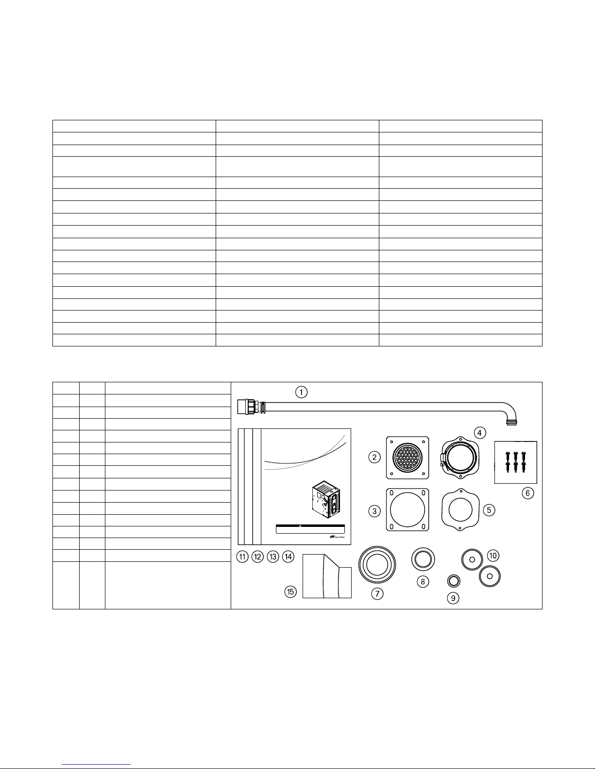
Document Pack Contents
Item Qty. Description
1 1 Condensate Drain Tube Assembly
2 1
3 1
Inlet Vent
Inlet Vent Gasket
4 1 Outlet Vent Assembly
5 1 Outlet Vent Gasket
6 6 Screws
7 1 Condensate Trap Grommet
8 1 Plug — Condensate/Gas
9 1 Plug — Electrical
10 2 Grommet — Condensate/Gas
11 1 Installer’s Guide
12 1 Service Facts
13 1 Owner Guide
14 1 Limited Warranty
15 1 2” to 3” Coupling — CPL00938
(a)
3” inlet vent supplied with S9V2D120UPSBA and S9V2D120DPSBA only. 2” inlet vent supplied with all other models.
(b)
Supplied with S9V2D120U5PSBA and S9V2D120D5PSBA only
(a)
(b)
18-CE01D1-1F-EN
9
Page 10

Furnace Installation Guidelines
The following sections give general guidelines for the
installation of the gas furnaces.
Safety Practices and Precautions
The following safety practices and precautions must be
followed during the installation, servicing, and
operation of this Furnace.
1. Use only with the type gas approved for this
Furnace. Refer to the Furnace rating plate.
2. Install the Furnace only in a location and position as
specified in “Locations and Clearances” of these
instructions.
3. Provide adequate combustion and ventilation air to
the Furnace space as specified in “Air for
Combustion and Ventilation” of these instructions.
4. Combustion products must be discharged
outdoors. Connect this Furnace to an approved vent
system only, as specified in the “Venting” section
of these instructions.
5. Never test for gas leaks with an open flame. Use a
commercially available soap solution made
specifically for the detection of leaks to check all
connections, as specified in the “Gas Piping”
section of these instructions.
6. Always install the Furnace to operate within the
Furnace’s intended temperature-rise range with a
duct system which has an external static pressure
within the allowable range, as specified on the unit
rating plate. Airflow within temperature rise for cfm
versus static is shown in the Service Facts
accompanying this Furnace.
7. When a Furnace is installed so that the supply ducts
carry air circulated by the Furnace to areas outside
the space containing the Furnace, the return air
shall also be handled by a duct(s) sealed to the
Furnace casing and terminating outside the space
containing the Furnace.
8. A gas-fired Furnace for installation in a residential
garage must be installed as specified in "Location
and Clearances" section of these instructions.
9. For non-Canadian applications, the furnace may be
used for temporary heating of buildings or
structures under construction only when the
following conditions have been met:
IImmppoorrttaanntt:: Gas furnaces manufactured on or after May
1, 2017 are not permitted to be used in
Canada for heating buildings or structures
under construction.
a. The Furnace venting system must be complete
and installed per manufacturer’s instructions.
b. The Furnace is controlled only by a room
Comfort Control (no field jumpers).
c. The Furnace return air duct must be complete
and sealed to the Furnace.
d. The Furnace input rate and temperature rise
must be verified to be within the nameplate
marking.
e. All air filters must be in place.
f. 100% of the Furnace combustion air
requirement must come from outside the
structure.
g. The Furnace return air temperature range is
between 55 and 80 Fahrenheit.
h. Clean the Furnace, duct work, and components
upon substantial completion of the construction
process, and verify Furnace operating
conditions including ignition, input rate,
temperature rise, and venting, according to the
manufacturer’s instructions.
10. IInn tthhee CCoommmmoonnwweeaalltthh ooff MMaassssaacchhuusseettttss,, tthhiiss
pprroodduucctt mmuusstt bbee ggaass ppiippeedd bbyy aa LLiicceennsseedd
PPlluummbbeerr oorr GGaass FFiitttteerr..
This Furnace is certified to leak 2% or less of nominal
air conditioning CFM delivered when pressurized to .5”
water column with all inlets, outlets, and drains sealed.
General Guidelines
The manufacturer assumes no responsibility for
equipment installed in violation of any code or
regulation.
It is recommended that Manual J of the Air
Conditioning Contractors Association (ACCA) or A.R.I.
230 be followed in estimating heating requirements.
When estimating heating requirements for installation
at Altitudes above 2000 ft., remember the gas input
must be reduced. See Combustion and Input Check.
MMaatteerriiaall iinn tthhiiss sshhiippmmeenntt hhaass bbeeeenn iinnssppeecctteedd aatt tthhee
ffaaccttoorryy aanndd rreelleeaasseedd ttoo tthhee ttrraannssppoorrttaattiioonn aaggeennccyy
wwiitthhoouutt kknnoowwnn ddaammaaggee.. IInnssppeecctt eexxtteerriioorr ooff ccaarrttoonn
ffoorr eevviiddeennccee ooff rroouugghh hhaannddlliinngg iinn sshhiippmmeenntt..
UUnnppaacckk ccaarreeffuullllyy aafftteerr mmoovviinngg eeqquuiippmmeenntt ttoo
aapppprrooxxiimmaattee llooccaattiioonn.. IIff ddaammaaggee ttoo ccoonntteennttss iiss
ffoouunndd,, rreeppoorrtt tthhee ddaammaaggee iimmmmeeddiiaatteellyy ttoo tthhee
ddeelliivveerriinngg aaggeennccyy..
Codes and local utility requirements governing the
installation of gas fired equipment, wiring, plumbing,
and flue connections must be adhered to. In the
absence of local codes, the installation must conform
with latest edition of the National Fuel Gas Code ANSI
Z223.1 / NFPA 54 • National Installation Code, CAN/CGA
B149.1. The latest code may be obtained from the
American Gas Association Laboratories, 400 N. Capitol
St. NW, Washington D.C. 20001.
1-800-699-9277 or www.aga.org.
10
18-CE01D1-1F-EN
Page 11
FFuurrnnaaccee IInnssttaallllaattiioonn GGuuiiddeelliinneess
These Furnaces have been classified as CATEGORY IV
furnaces in accordance with latest edition of ANSI
Z21.47 standards • CSA 2.3. Category IV furnaces
operate with positive vent static pressure and with a
flue loss less than 17 percent. These conditions require
special venting systems, which must be gas tight and
water tight. These Category IV Direct Vent Furnaces are
approved for installation in Manufactured/ Mobile
housing when used with BAYMFGH200A.
A manufactured (mobile) home installation must
conform with the Manufactured Home Construction
and Safety Standard, Title 24 CFR, Part 3280, or when
this Standard is not applicable, the Standard for
Manufactured Home Installations (Manufactured Home
Sites, Communities and Set-Ups), ANSI/NCS A225.1.
and/or MH Series Mobile Homes, CAN/CSA-Z240.
Locations and Clearances
The location of the Furnace is normally selected by the
architect, the builder, or the installer. However, before
the Furnace is moved into place, be sure to consider
the following requirements:
1. Is the location selected as near the chimney or vent
and as centralized for heat distribution as practical?
2. Do all clearances between the Furnace and
enclosure equal or exceed the minimums stated in
Clearance Table below?
Minimum clearance to combustible materials
Closet
Sides 0 In.
Back 1 In.
Top 1 In.
Front 0 In.
Bottom 0 In.
Flue 0 In.
24 In. minimum front clearance recommended for service
Horizontal Closet and Alcove
Right Side 0 In.
Left Side 0 In.
Back
Top 1 In.
Bottom 0 In.
Flue 0 In.
Horizontal Flue (discharge on left)
Closet
Right Side 0 In.
Left Side
Rear 1 In.
1 In.
0 In.
Top 1 In.
Bottom 0 In.
Flue 0 In.
3. Is there sufficient space for servicing the Furnace
and other equipment? A minimum of 24 inches
front accessibility to the Furnace must be provided.
Any access door or panel must permit removal of
the largest component.
4. Are there at least 3 inches of clearance between the
Furnace combustion air openings in the front panel
and any closed panel or door provided?
5. Are the ventilation and combustion air openings
large enough and will they remain unobstructed? If
outside air is used, are the openings set 12" above
the highest snow accumulation level?
6. Allow sufficient height in supply plenum above the
Furnace to provide for cooling coil installation, if
the cooling coil is not installed at the time of this
Furnace installation.
7. The Furnace shall be installed so electrical
components are protected from water.
8. If the Furnace is installed in a garage, it must be
installed so that the burners, and the ignition
source are located not less than 18 inches above the
floor and the Furnace must be located or protected
to avoid physical damage from vehicles.
9. The gas furnace must not be located where
excessive exposure to contaminated combustion
air will result in safety and performance related
problems. Avoid the following known
contaminants:
a. Permanent wave solutions
b. Chlorinated waxes and cleaners
c. Chlorine based swimming pool chemicals
d. Water softening chemicals
e. De-icing salts or chemicals
f. Carbon tetrachloride
g. Halogen type refrigerants
h. Cleaning solvents (such as
perchloroethylene)
i. Printing inks, paint removers, varnishes, etc.
j. Hydrochloric acid
k. Cements and glues
l. Antistatic fabric softeners for clothes dryers
m. Masonry acid washing materials
IMPORTANT: The Furnace must be installed level. The
only allowable variation would be slightly to the left
and/ or forward in upflow installations or slightly
toward the front in horizontal installations. This is
necessary for proper condensate drainage.
18-CE01D1-1F-EN
11
Page 12
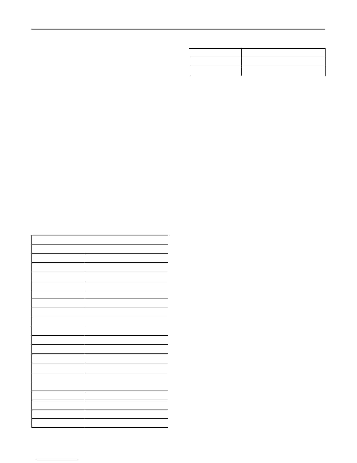
Outline Drawings
12
18-CE01D1-1F-EN
Page 13

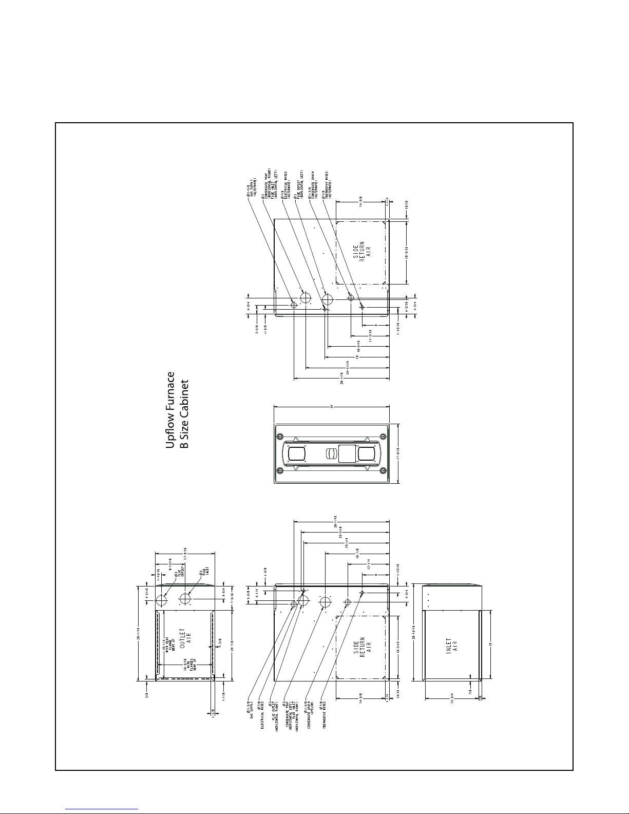
OOuuttlliinnee DDrraawwiinnggss
18-CE01D1-1F-EN
13
Page 14

OOuuttlliinnee DDrraawwiinnggss
14
18-CE01D1-1F-EN
Page 15

OOuuttlliinnee DDrraawwiinnggss
18-CE01D1-1F-EN
15
Page 16

OOuuttlliinnee DDrraawwiinnggss
16
18-CE01D1-1F-EN
Page 17

OOuuttlliinnee DDrraawwiinnggss
18-CE01D1-1F-EN
17
Page 18

Furnace General Installation
Fits 5/16” Allen wrench
The following sections give general instructions for the
installation of the gas furnaces.
Note: Use a 5/16” Allen wrench to remove the front panel.
S-Series Furnace Panel Removal
18
18-CE01D1-1F-EN
Page 19

Gas Piping
FFuurrnnaaccee GGeenneerraall IInnssttaallllaattiioonn
Important: When converting the gas piping from the factory default,
Upflow furnace with gas piping on left side
Downflow furnace with gas piping on left side Downflow furnace with gas piping on right side
the plug must be removed from the new gas piping
location and swapped with the grommet from the default
location. The upflow furnace default is left side gas
piping. The downflow furnace default is right side gas
piping.
Upflow furnace with gas piping on right side
18-CE01D1-1F-EN
19
Page 20

FFuurrnnaaccee GGeenneerraall IInnssttaallllaattiioonn
Important: When converting the gas piping from the factory default,
Horizontal left furnace with gas piping out left side
Horizontal right furnace with gas piping out left side Horizontal right furnace with gas piping out right side
the plug must be removed from the new gas piping
location and swapped with the grommet from the default
location. The upflow furnace default is left side gas
piping. The downflow furnace default is right side gas
piping.
Horizontal left furnace with gas piping out right side
20
18-CE01D1-1F-EN
Page 21

The upflow/horizontal furnace is shipped standard for left side
installation of gas piping. An opening with plug is provided on the right
side for an alternate gas piping arrangement.
The installation of piping shall be in accordance with piping codes and
the regulations of the local gas company. Pipe joint compound must be
resistant to the chemical reaction with liquefied petroleum gases.
Important: If local codes allow the use of flexible gas appliance
connector, always use a new listed connector. Do not use
a connector which has previously service another gas
appliance.
Refer to the piping table for delivery sizes. Connect gas supply to the
unit, using a ground joint union and a manual shut-off valve. National
codes require a condensation drip leg to be installed ahead of the gas
valve.
The furnace and its individual shut-off valve must be disconnected
from the gas supply piping system during any pressure testing of that
system at test pressures in excess of 1/2 psig (3.5 kPa).
The furnace must be isolated from the gas supply piping by closing its
individual manual shut-off valve during any pressure testing of the
gas supply piping system at test pressures equal to or less than 1/2
psig (3.5 kPa).
Note: Maximum pressure to the gas valve for natural gas is 13.8" W.
C. Minimum pressure is 5.0" W.C. Maximum pressure to the
gas valve for propane is 13.8" W.C. Minimum pressure is 10.0"
W.C.
All gas fittings must be checked for leaks using a soapy solution before
lighting the furnace.DO NOT CHECK WITH AN OPEN FLAME!
For LP conversions on all S-Series Furnaces, use BAYLPSS400A
conversion kit with stainless steel burners.
When installing our furnaces in a manufactured house, use.
Manufactured Housing Accessory Kit, BAYMFGH200A.
FFuurrnnaaccee GGeenneerraall IInnssttaallllaattiioonn
NATURAL GAS ONLY
TABLE OF CUBIC FEET PER HOUR OF GAS
FOR VARIOUS PIPE SIZES AND LENGTHS
PIPE
SIZE
1/2 132 92 73 63 56 50 46
3/4 278 190 152 130 115 105 96
1–1/4 1050 730 590 520 440 400 370
This table is based on Pressure Drop of 0.3 inch W.C. and 0.6 SP.
GR. Gas
10 20 30 40 50 60 70
1 520 350 285 245 215 195 180
INPUT
RATING
BTUH
40,000 2 45 56
60,000 3 45 56
80,000 4 45 56
100,000 5 45 56
120,000 6 45 56
NUMBER OF
BURNERS
LENGTH OF PIPE
ORIFICE SIZES
MAIN BURNER ORIFICE
DRILL SIZE
NAT. GAS LP GAS
18-CE01D1-1F-EN
21
Page 22

FFuurrnnaaccee GGeenneerraall IInnssttaallllaattiioonn
Combustion and Input Check
1. Make sure all gas appliances are off except the furnace.
2. Clock the gas meter with the furnace operating (determine the
dial rating of the meter) for one revolution.
3. Match the "Sec" column in the gas flow (in cfh) the table with the
time clocked.
4. Read the "Flow" column opposite the number of seconds clocked.
5. Use the following factors if necessary:
a. For 1 Cu. Ft. Dial Gas Flow CFH = Chart Flow Reading ÷ 2
b. For 1/2 Cu Ft. Dial Gas Flow CFH = Chart Flow Reading ÷ 4
c. For 5 Cu. Ft. Dial Gas Flow CFH = 10X Chart Flow Reading ÷ 4
6. Multiply the final figure by the heating value of the gas obtained
from the utility company and compare to the nameplate rating.
This must not exceed the nameplate rating.
Gas Flow in Cubic Feet Per Minute
2 Cubic Foot Dial
Sec. Flow Sec. Flow Sec. Flow Sec. Flow
8 900 29 248 50 144 82 88
9 800 30 240 51 141 84 86
10 720 31 232 52 138 86 84
11 655 32 225 53 136 88 82
12 600 33 218 54 133 90 80
13 555 34 212 55 131 92 78
14 514 35 206 56 129 94 76
15 480 36 200 57 126 96 75
16 450 37 195 58 124 98 73
17 424 38 189 59 122 100 72
18 400 39 185 60 120 104 69
19 379 40 180 62 116 108 67
20 360 41 176 64 112 112 64
21 343 42 172 66 109 116 62
22 327 43 167 68 106 120 60
23 313 44 164 70 103 124 58
24 300 45 160 72 100 128 56
25 288 46 157 74 97 132 54
26 277 47 153 76 95 136 53
27 267 48 150 78 92 140 51
28 257 49 147 80 90 144 50
22
18-CE01D1-1F-EN
Page 23

Gas Valve Adjustment
Changes can be made by adjusting the manifold pressure, or changing
orifices (orifice change may not always be required). To adjust the
manifold pressure:
1. Turn off all electrical power to the system.
2. Attach a manifold pressure gauge with flexible tubing to the outlet
pressure boss marked "OUT P" on White- Rodgers gas valve
model 36J.
3. Loosen (Do Not remove) the pressure tap test set screw one turn
with 3/32" hex wrench.
a. The pressure tap adjustment kit (KIT07611) contains a 3/32"
hex wrench, a 5/16" hose and a connector and can be
ordered through Global Parts.
4. Turn on system power and energize valve.
5. Adjust 1st stage gas heat by removing the low (LO) adjustment
regulator cover screw.
a. To increase outlet pressure, turn the regulator adjust screw
clockwise.
b. To decrease outlet pressure, turn the regulator adjust screw
counterclockwise.
c. Adjust regulator until pressure shown on manometer
matches the pressure specified in the table.
The input of no more than nameplate rating and no less than
93% of the nameplate rating, unless the unit is derated for
high altitude.
d. Replace and tighten the regulator cover screw securely.
6. Adjust 2nd stage gas heat by removing the high (HI) adjustment
regulator cover screw.
a. To increase outlet pressure, turn the regulator adjust screw
clockwise.
b. To decrease outlet pressure, turn the regulator adjust screw
counterclockwise.
c. Adjust regulator until pressure shown on manometer
matches the pressure specified in the table.
The input of no more than nameplate rating and no less than
93% of the nameplate rating, unless the unit is derated for
high altitude.
d. Replace and tighten the regulator cover screw securely.
7. Cycle the valve several times to verify regulator setting.
a. Repeat steps 5-7 if needed.
8. Turn off all electrical power to the system.
9. Remove the manometer and flexible tubing and tighten the
pressure tap screw.
10. Using a leak detection solution or soap suds, check for leaks at the
pressure outlet boss and pressure tap test screw.
11. Turn on system power and check operation of the unit.
FFuurrnnaaccee GGeenneerraall IInnssttaallllaattiioonn
Fuel Manifold Pressure Settings (inches w.c.)
Fuel 2nd Stage Max. 1st Stage Max.
Natural Gas 3.5” W.C. 1.7” W.C.
LP Gas 10.0” W.C. 6.0” W.C.
18-CE01D1-1F-EN
23
Page 24

FFuurrnnaaccee GGeenneerraall IInnssttaallllaattiioonn
High Altitude Derate
Input ratings (BTUH) of these Furnaces are based on sea level
operation and should not be changed at elevations up to 2,000 ft. (610
m).
If the installation is 2,000 ft. (610 m) or above, the Furnace input rate
(BTUH) shall be reduced 4% for each 1,000 ft. above sea level.
Installations of this furnace at altitudes above 2,000 ft. (610 m) shall
be made utilizing the Vent Length table and/or Part Numbers for
Replacement Orifices table in these installation instructions.
The Furnace input rate shall be checked by clocking the gas flow rate
(CFH) and multiplying by the heating value obtained from the local
utility supplier for the gas being delivered at the installed altitude.
Input rate changes can be made by adjusting the Manifold Pressure
(min 3.0 - max 3.7 in. W.C. - Natural Gas) or changing orifices (orifice
change may not always be required).
If the desired input rate can not be achieved with a change in Manifold
Pressure, then the orifices must be changed. LP installations will
require an orifice change.
Important: Reinstall the replacement orifices to the same depth as
the orifices supplied with the equipment.
See the table for help in selecting orifices if orifice change is required.
Furnace input rate and temperature rise should be checked again after
changing orifices to confirm the proper rate for the altitude.
The vent length table shows the required vent lengths for installations
at various altitudes. Installations above 12,000 feet are not allowed.
Turn the main Gas Valve toggle switch within the unit to the "OFF"
position. Turn the external gas valve to "ON". Purge the air from the
gas lines. After purging, check all gas connections for leaks with a
soapy solution – DO NOT CHECK WITH AN OPEN FLAME. Allow 5
minutes for any gas that might have escaped to dissipate.
LP Gas being heavier than air may require forced ventilation. Turn the
toggle switch on the Gas Valve in the unit to the "ON" position.
PART NUMBERS FOR REPLACEMENT ORIFICES
DRILL SIZE PART
NUMBER
44 ORF00501 54 ORF00555
45 ORF00644 55 ORF00693
46 ORF00909 56 ORF00907
47 ORF00910 57 ORF00908
48 ORF01099 58 ORF01338
49 ORF00503 59 ORF01339
50 ORF00493
DRILL SIZE PART
NUMBER
The table lists the main burner orifices
used with the furnace. If a change of
orifices is required to correct the furnace
input rating refer to the part number for
replacement orifices table.
Installation of this furnace at altitudes
above 2000 ft (610m) shall be in
accordance with local codes, or in the
absence of local codes, the National Fuel
Gas Code, ANSI Z223.1/NFPA 54 or
National Standard of Canada, Natural
Gas and Propane Installation Code, CSA
B149.1.
Orifice
Twist Drill
Size If
Installed at
Sea Level
42 42 43 43 43 44 44 45 46 47
43 44 44 44 45 45 46 47 47 48
44 45 45 45 46 47 47 48 48 50
45 46 47 47 47 48 48 49 49 50
46 47 47 47 48 48 49 49 50 51
47 48 48 49 49 49 50 50 51 52
54 54 55 55 55 55 55 56 56 56
55 55 55 55 56 56 56 56 56 57
56 56 56 57 57 57 58 59 59 60
57 58 59 59 60 60 61 62 63 63
58 59 60 60 61 62 62 63 63 64
From National Fuel Gas Code — Table F-4
2000 3000 4000 5000 6000 7000 8000 9000 10000
Altitude Above Sea Level
and Orifice Required at Other Elevations
24
18-CE01D1-1F-EN
Page 25

General Venting
FIELD SUPPLIED
2” COUPLING
LABEL
SAYS
“TOP”
2" TO 3" COUPLING
CPL00938
BAYREDUCE may be
used in Canadian
applications to meet
ULC-S636
CPL00938 IS FACTORY
SUPPLIED ONLY WITH THE
120,000 BTUH UPFLOW
FURNACE MODELS
FIELD SUPPLIED
2” COUPLING
2" TO 3" COUPLING
CPL00938 IS FACTORY
SUPPLIED ONLY WITH THE
120,000 BTUH UPFLOW
FURNACE MODELS
CPL00938
BAYREDUCE may be
used in Canadian
applications to meet
ULC-S636
FFuurrnnaaccee GGeenneerraall IInnssttaallllaattiioonn
FURNACE EXHAUST MUST BE VENTED TO THE OUTDOORS. THESE
FURNACES ARE INDUCED DRAFT VENTED AND MUST NOT BE
CONNECTED TO ANY VENT SERVING ANOTHER APPLIANCE. PLEASE
NOTE THAT THESE FURNACES USE POSITIVE-PRESSURE VENT
SYSTEMS.
Proper venting is essential to obtain maximum efficiency from a
condensing Furnace. Proper installation of the vent system is
necessary to assure drainage of the condensate and prevent
deterioration of the vent system.
ETL has certified the design of condensing Furnaces for a minimum of
0" clearance from combustible materials to single wall plastic vent
pipe.
The recommended system is assembled from 2" or 3" plastic pipe and
fittings found in the Approved Vent Pipe Materials Table. Where the
system is routed to the outdoors through an existing masonry
chimney containing flue products from another gas appliance, or
where required by local codes, then 3" venting of Type 29- 4C
stainless steel must be used in place of PVC material.
These Furnaces have been classified as CATEGORY IV Furnaces in
accordance with ANSI Z21.47 “latest edition” standards. Category IV
Furnaces operate with positive vent pressure and with a vent gas
temperature less than 140°F above the dewpoint. These conditions
require special venting systems, which must be gas tight and water
tight.
3” Venting requirements
Important: To determine if your application requires 3” venting, see
the Maximum Vent Length Table.
Important: Horizontal venting application must use the 2” x 3” offset
reducing coupling. Vertical venting applications to not
require the reducing coupling to be offset.
When the vent pipe is exposed to temperatures below
freezing, e.g., when it passes through unheated spaces, etc.,
the pipe must be insulated with 1/2 inch (22.7 mm) thick
Armaflex-type insulation or equal.
If the space is heated sufficiently to prevent freezing, then the
insulation will not be required. If domestic water pipes are not
protected from freezing then the space meets the condition of
a heated space.
Note: If your furnace comes with a factory supplied 2" X 3" offset
reducing coupling it is used for 3" vent pipe installation. Make
sure the marking "TOP" is located on the top side of the pipe in
horizontal venting applications. The straight side of the
coupling must be on bottom for proper drainage of condensate.
Note: For Canadian applications, BAYREDUCE 2” x 3” offset reducing
coupling meets ULC-S636 requirements. Make sure the
marking "TOP" is located on the top side of the pipe. The
straight side of the coupling must be on bottom for proper
drainage of condensate in horizontal venting.
Note: When an existing Furnace is removed from a venting system
serving other gas appliances, the venting system is likely to be
too large to properly vent the remaining attached appliances.
Important: These Furnaces may be installed as Direct Vent (sealed
combustion) or as Nondirect Vent (single pipe). The
Furnaces are shipped DIRECT VENT with sealed
combustion.
Important: Products installed in Canada must use vent systems that
are certified to the Standard for Type BH Gas Venting
Systems (ULC S636) for Class II-A venting systems (up
to 65°C). Components of the vent system must not be
interchanged with other vent systems or unlisted pipe or
fittings. Plastic components, specified primers, and glues
must be from a single system manufacturer and not
intermixed with other system manufacturer's vent
system parts. In addition, the first three feet of the vent
pipe must be visible for inspection.
18-CE01D1-1F-EN
25
Page 26

FFuurrnnaaccee GGeenneerraall IInnssttaallllaattiioonn
Special Case Venting
Special instructions for direct vent furnace air intake.
In certain applications, particularly when the furnace is located in a
basement, there are certain conditions that can be met where warm
humid air from the outside is drawn into combustion air piping. If the
area where the piping is located is conditioned below 70° F,
condensation could occur inside the piping and ultimately drain into
the furnace compartment, which could lead to premature component
failure.
We recommend following one of the options to prevent this condition
from occurring and possibly damaging components within the
furnace:
Option 1
If possible, slope the inlet combustion air piping away from the
furnace. Condensation that may occur will now drain outside of the
home. The combustion air outlet piping must remain sloped back to
the furnace.
Note: Inlet air piping is not considered to be part of the venting
system. The inlet air piping may be made from PVC.
26
18-CE01D1-1F-EN
Page 27

Option 2 — Top combustion air intake
If sloping the combustion air intake pipe is not possible, install a DWV
Tee as close to the furnace as possible with drain and trap to prevent
condensation from occurring in the furnace cabinet. Do not tee AC
condensate and combustion air condensate trap together.
FFuurrnnaaccee GGeenneerraall IInnssttaallllaattiioonn
Option 3 — Side combustion air intake
If sloping the combustion air intake pipe is not possible, install a
sanitary Tee as close to the furnace as possible with drain and trap.
18-CE01D1-1F-EN
27
Page 28

Furnace
Vent
Air
Inlet
Furnace
Air
Inlet
Vent
Attic
Vent
(See Note)
FFuurrnnaaccee GGeenneerraall IInnssttaallllaattiioonn
Vent Terminations
For DIRECT VENT APPLICATION: The Furnaces must be vented to
the exterior of the house and combustion air MUST come through the
inlet air pipe from OUTSIDE AIR.
Note: BAYVENT* accessories can be used for inlet and outlet
terminals when the pipes do not exit the structure together. For
Canadian applications, venting systems must meet ULC-S636
requirements.
For NONDIRECT VENT APPLICATION: The Furnace shall be vented
to the exterior of the house, but combustion air may enter from the
surrounding area as long as combustion air requirements are met.
(See AIR FOR COMBUSTION AND VENTILATION)
FURNACE VENT / INLET PIPE INSTALLATION IN TWO
PRESSURE ZONE CONFIGURATIONS ARE NOT ALLOWED
Note: For single pressure zone applications, see the Horizontal
Venting section.
The following are EXAMPLES ONLY.
EX. 1—
Example 1 shows the vent pipe exhausting through the roof and the
inlet air coming from the interior of the house. The inlet air coming
from the interior of the house must meet combustion requirements for
area, etc., as shown in the section AIR FOR COMBUSTION AND
VENTILATION in this Installer’s Guide.
Vent terminations
• BAYVENT200B
• BAYAIR30AVENTA
Vent terminations — Canadian applications. Meets ULC-S636
requirements.
• BAYVENTCN200B
• BAYAIR30CNVENT
EX. 2—
The inlet air does not have to come from outside the structure.
Example 2 shows the inlet air, may come from the attic if the
requirements for combustion air are met as shown in the section AIR
FOR COMBUSTION AND VENTILATION.
Note: If only the flue gas pipe is to the outside of the structure, a
straight section of pipe (long enough to exit the Furnace
cabinet) must be attached to the inlet air side with an elbow
(which is 5 to 10 equiv. ft.) installed on the end to prevent dust
and debris from falling directly into the Furnace.
Attaching Vent Piping
VENT FITTING MATERIAL – PLASTIC
Gas and liquid tight single wall vent fittings, designed for resistance to
corrosive flue condensate, MUST be used throughout.
Listed in the Approved Vent Pipe Materials table are designations for
different types of 2" and 3" size pipe and fittings that meet these
requirements. The materials listed are various grades of PVC, CPVC,
ABS, and DuraVent PolyPro®.
28
18-CE01D1-1F-EN
Page 29

ATTACHING VENT PIPING
FFuurrnnaaccee GGeenneerraall IInnssttaallllaattiioonn
Important: Products installed in Canada must use vent systems that
are certified to the Standard for Type BH Gas Venting
Systems (ULC S636) for Class II-A venting systems (up
to 65°C). Components of the vent system must not be
interchanged with other vent systems or unlisted pipe or
fittings. Plastic components, specified primers, and glues
must be from a single system manufacturer and not
intermixed with other system manufacturer's vent
system parts. In addition, the first three feet of the vent
pipe must be visible for inspection.
PIPE JOINTS: All joints must be fastened and sealed per manufacturer
instructions and local and national codes to prevent escape of
combustion products into the building.
MANUFACTURED MODULAR VENTING SYSTEMS
WWAARRNNIINNGG
CCAARRBBOONN MMOONNOOXXIIDDEE PPOOIISSOONNIINNGG
HHAAZZAARRDD!!
FFaaiilluurree ttoo ffoollllooww tthhiiss WWaarrnniinngg mmaayy rreessuulltt iinn pprrooppeerrttyy
ddaammaaggee,, sseevveerree ppeerrssoonnaall iinnjjuurryy,, oorr ddeeaatthh..
SSeeee tthhee AApppprroovveedd VVeenntt PPiippee MMaatteerriiaallss ttaabbllee ffoorr
mmaannuuffaaccttuurreedd mmoodduullaarr vveennttiinngg ssyysstteemmss tthhaatt aarree
aapppprroovveedd ffoorr uussee wwiitthh tthhiiss pprroodduucctt.. FFoollllooww tthhee
mmaannuuffaaccttuurreerr’’ss iinnssttaallllaattiioonn iinnssttrruuccttiioonnss wwhheenn
iinnssttaalllliinngg tthhee vveennttiinngg ssyysstteemm..
For manufactured modular venting systems that are approved with
this product see PVC vent fitting material table. Do not drill into
polypropelene venting pipes
WWAARRNNIINNGG
CCAARRBBOONN MMOONNOOXXIIDDEE PPOOIISSOONNIINNGG
HHAAZZAARRDD!!
FFaaiilluurree ttoo ffoollllooww tthhiiss WWaarrnniinngg mmaayy rreessuulltt iinn pprrooppeerrttyy
ddaammaaggee,, sseevveerree ppeerrssoonnaall iinnjjuurryy,, oorr ddeeaatthh..
DDoo nnoott uussee cceemmeenntt oonn ppoollyypprrooppyylleennee vveennttiinngg
ssyysstteemmss.. FFoollllooww tthhee mmaannuuffaaccttuurreerr’’ss iinnssttaallllaattiioonn
iinnssttrruuccttiioonnss wwhheenn iinnssttaalllliinngg tthhee vveennttiinngg ssyysstteemm..
BONDING OF PVC
Note: It is recommended that the first joints from the Furnace be
connected and sealed with high temperature RTV. This will
enable the pipes to be removed later without cutting.
Be sure to properly support these joints.
Commercially available solvent cement for PVC must be used to join
PVC pipe fittings. Follow instructions on container carefully.
Pipe and Fitting – ASTM D1785, D2466, D2661, & D2665
PVC Primer and Solvent Cement – ASTM D2564
Procedure for Cementing Joints – Ref ASTM D2855
1. Cut pipe square, remove ragged edges and burrs. Chamfer end of
pipe, then clean fitting socket and pipe joint area of all dirt,
grease, moisture or chips.
2. After checking pipe and socket for proper fit, wipe socket and pipe
with cleaner-primer. Apply a liberal coat of primer to inside
surface of socket and outside of pipe.
DO NOT ALLOW PRIMER TO DRY BEFORE APPLYING CEMENT.
3. Apply a thin coat of cement evenly in the socket. Quickly apply a
heavy coat of cement to the pipe end and insert pipe into fitting
with a slight twisting movement until it bottoms out.
4. Hold the pipe in the fitting for 30 seconds to prevent tapered
socket from pushing the pipe out of the fitting.
5. Wipe all excess cement from the joint with a rag. Allow 15
minutes before handling. Cure time varies according to fit,
temperature and humidity.
Connection of the pipe and collar of the combustion air inlet should
just be a friction fit. It is recommended that the inlet air joint be sealed
with RTV type sealant to allow the joint to be separated for possible
future service. The inlet and vent pipes must be properly supported
throughout the entire length.
Note: Follow venting instructions carefully when using PVC cement.
Important: All joints must be water tight. Flue condensate is
somewhat acidic, and leaks can cause equipment
damage.
18-CE01D1-1F-EN
29
Page 30

FFuurrnnaaccee GGeenneerraall IInnssttaallllaattiioonn
APPROVED VENT PIPE MATERIALS
PVC VENT FITTING MATERIAL
These fittings are available from your Gas Furnace Distributors.
PLASTIC VENT PIPE DESIGNATIONS
PVC
ASTM STANDARD PIPE TYPE ALLOWABLE TEMPERATURE °F MARKING
F891 CELLULAR CORE 158 ASTM F891
D2665 DWV PIPE 158 ASTM D2665
D1785 SCH 40, 80, 120 158 ASTM D1785
D2241 SDR SERIES 158 ASTM D2241
CPVC
ASTM STANDARD PIPE TYPE ALLOWABLE TEMPERATURE °F MARKING
D2846 CPVC 41 212 ASTM D2846
F441 SCH 40, 80 212 ASTM F441
F442 SDR SERIES 212 ASTM F442
ABS
ASTM STANDARD PIPE TYPE ALLOWABLE TEMPERATURE °F MARKING
D2661 SCH 40 DWV 180 ASTM D2661
F628 SCH 40 DWV CELLULAR CORE 180 ASTM F628
DuraVent PolyPro®
ASTM STANDARD PIPE TYPE ALLOWABLE TEMPERATURE °F MARKING
N/A N/A 230 ULC-S636
30
18-CE01D1-1F-EN
Page 31

FFuurrnnaaccee GGeenneerraall IInnssttaallllaattiioonn
Maximum Vent Length Table
Maximum Vent Length Table
Model
S9V2B040U3PS, S9V2B040D3PS,
S9V2B060U3PS, S9V2B060D3PS,
S9V2B060U4PS
S9V2B080U3PS, S9V2B080D3PS,
S9V2B080U4PS, S9V2B080D4PS,
S9V2C080U5PS
S9V2C100U4PS, S9V2C100D4PS,
S9V2C100U5PS, S9V2C100D5PS
S9V2D120U5PS, S9V2D120D5PS
S9V2B040U3PS, S9V2B040D3PS,
S9V2B060U3PS, S9V2B060D3PS,
S9V2B060U4PS
S9V2B080U3PS, S9V2B080D3PS,
S9V2B080U4PS, S9V2B080D4PS,
S9V2C080U5PS
S9V2C100U4PS, S9V2C100D4PS,
S9V2C100U5PS, S9V2C100D5PS
S9V2D120U5PS, S9V2D120D5PS
S9V2B040U3PS, S9V2B040D3PS,
S9V2B060U3PS, S9V2B060D3PS,
S9V2B060U4PS
S9V2B080U3PS, S9V2B080D3PS,
S9V2B080U4PS, S9V2B080D4PS,
S9V2C080U5PS
S9V2C100U4PS, S9V2C100D4PS,
S9V2C100U5PS, S9V2C100D5PS
S9V2D120U5PS, S9V2D120D5PS
S9V2B040U3PS, S9V2B040D3PS,
S9V2B060U3PS, S9V2B060D3PS,
S9V2B060U4PS
S9V2B080U3PS, S9V2B080D3PS,
S9V2B080U4PS, S9V2B080D4PS,
S9V2C080U5PS
S9V2C100U4PS, S9V2C100D4PS,
S9V2C100U5PS, S9V2C100D5PS
S9V2D120U5PS, S9V2D120D5PS
Notes:
1. Not allowed
2. FOR DURAVENT MANUFACTURED MODULAR VENTING SYSTEMS THAT ARE IN THE APPROVED VENT PIPE MATERIAL TABLE,
EQUIVALENT VENT LENGTHS MAY BE DIFFERENT FROM WHAT IS SHOWN ABOVE. REFER TO THE VENTING SYSTEM
MANUFACTURER'S INSTALLATION INSTRUCTIONS FOR APPROPRIATE VENTING DIAMETERS AND EQUIVALENT LENGTHS.
3. Minimum vent length for all models: 15' equivalent.
4. DO NOT MIX PIPE DIAMETERS IN THE SAME LENGTH OF PIPE OUTSIDE THE FURNACE CABINET (Except adapters at the top of the furnace).
If different inlet and vent pipe sizes are used, the vent pipe must adhere to the maximum length limit shown in the table above (See note 7
below for exception). The inlet pipe can be of a larger diameter, but never smaller than the vent pipe.
5. MAXIMUM PIPE LENGTHS MUST NOT BE EXCEEDED! THE LENGTH SHOWN IS NOT A COMBINED TOTAL, IT IS THE MAXIMUM LENGTH OF
EACH (Vent or Inlet air pipes).
6. One SHORT radius 90° elbow is equivalent to 10' of 4" pipe, 10' of 3" pipe, or 8’ of 2" pipe. One LONG radius elbow is equivalent to 6' of 4"
pipe, 7’ of 3" pipe, or 5' of 2" pipe. Two 45° elbows equal one 90° LONG elbow. One MITERED elbow is equivalent to 12’ of 3” pipe or 12’ of
2” pipe.
7. The termination tee or bend must be included in the total number of elbows. If the BAYAIR30AVENTA or BAYAIR30CNVENT termination kit
is used, the equivalent length of pipe is 5 feet. For BAYVENT200B and BAYVENTCN200B the equivalent length is 0 feet.
8. For Canadian applications, venting systems must meet ULC-S636 requirements.
9. The INLET AIR of one pipe systems require the installation of a minimum of one 90° elbow (to prevent dust and debris from falling straight
into the furnace).
2 Inch or 2.5 Inch Pipe 3 Inch or 4 Inch Pipe
Altitude 0–2,000 Feet
Altitude 2,001–5,400 Feet
Altitude 5,401–7,800 Feet
Altitude 7,801–10,100 Feet
Maximum Total Equivalent Length In Feet
for Vent and Inlet Air (See Notes)
200 200
100 200
50 200
Note 1 200
200 200
80 120
50 150
Note 1 200
100 150
50 70
Note 1 100
Note 1 100
90 90
Note 1 50
Note 1 50
Note 1 50
18-CE01D1-1F-EN
31
Page 32

FIELD SUPPLIED
2” COUPLING
LABEL
SAYS
“TOP”
2" TO 3" COUPLING
CPL00938
BAYREDUCE may be
used in Canadian
applications to meet
ULC-S636
CPL00938 IS FACTORY
SUPPLIED ONLY WITH THE
120,000 BTUH UPFLOW
FURNACE MODELS
FIELD SUPPLIED
2” COUPLING
2" TO 3" COUPLING
CPL00938 IS FACTORY
SUPPLIED ONLY WITH THE
120,000 BTUH UPFLOW
FURNACE MODELS
CPL00938
BAYREDUCE may be
used in Canadian
applications to meet
ULC-S636
FFuurrnnaaccee GGeenneerraall IInnssttaallllaattiioonn
Horizontal Venting
3” Venting requirements
Important: To determine if your application requires 3” venting, see
Important: Horizontal venting application must use the 2” x 3” offset
When the vent pipe is exposed to temperatures below
freezing, e.g., when it passes through unheated spaces, etc.,
the pipe must be insulated with 1/2 inch (22.7 mm) thick
Armaflex-type insulation or equal.
If the space is heated sufficiently to prevent freezing, then the
insulation will not be required. If domestic water pipes are not
protected from freezing then the space meets the condition of
a heated space.
Note: If your furnace comes with a factory supplied 2" X 3" offset
Note: For Canadian applications, BAYREDUCE 2” x 3” offset reducing
the Maximum Vent Length Table.
reducing coupling. Vertical venting applications to not
require the reducing coupling to be offset.
reducing coupling it is used for 3" vent pipe installation. Make
sure the marking "TOP" is located on the top side of the pipe in
horizontal venting applications. The straight side of the
coupling must be on bottom for proper drainage of condensate.
coupling meets ULC-S636 requirements. Make sure the
marking "TOP" is located on the top side of the pipe. The
straight side of the coupling must be on bottom for proper
drainage of condensate in horizontal venting.
32
18-CE01D1-1F-EN
Page 33

COMBUSTIBLE MATERIAL WALL
A minimum clearance of 1" to combustible materials must be
maintained when using single wall stainless steel venting.
Shield material to be a minimum of 24 gauge stainless or aluminized
sheet metal. Minimum dimensions are 12"x12". Shield must be
fastened to both inside and outside of wall. Use screws or anchor type
fasteners suited to the outside or inside wall surfaces.
NONCOMBUSTIBLE MATERIAL WALL
The hole through the wall must be large enough to maintain pitch of
vent and properly seal.
Use cement mortar seal on inside and outside of wall.
FFuurrnnaaccee GGeenneerraall IInnssttaallllaattiioonn
18-CE01D1-1F-EN
33
Page 34

6” Min.
24” Max
12” Min.
15” Max
9” Minimum
minimum from end
of exhaust pipe to
end of inlet pipe
6” Min.
24” Max
12” Min.
15” Max
9” Minimum
minimum from end
of exhaust pipe to
end of inlet pipe
6” Min.
24” Max
12” Min.
15” Max
9” Minimum
minimum from end
of exhaust pipe to
end of inlet pipe
4” Min.
24” Max
4” Min.
24” Max
FFuurrnnaaccee GGeenneerraall IInnssttaallllaattiioonn
Table 2. Horizontal Venting Through Wall
The vent for this appliance shall not terminate
1. Over public walkways; or
2. Near soffit vents or crawl space vents or other areas where condensate or vapor could create a nuisance or hazard or cause property
damage; or
3. Where condensate vapor could cause damage or could be detrimental to the operation of regulators, relief valves. or other equipment.
Possible configurations for two pipe venting system. Both terminations must be located in the same pressure zone.
Important: Maintain 12” minimum clearance above highest anticipated snow level or grade, whichever is greater.
Note: All distances are centerline to centerline.
34
18-CE01D1-1F-EN
Page 35

Horizontal Venting Through Wall with Concentric Vent Kit
VENT
COMBUSTION
AIR
VENT
VENT
PLATE
VENT
CAP
12" MINIMUM
TO OVERHANG
MAINTAIN 12" MINIMUM CLEARANCE
ABOVE HIGHEST ANTICIPATED SNOW LEVEL
OR GRADE WHICHEVER IS GREATER
SCREWS
(4 req.)
ANCHORS
(4 req.)
7.2"
3.2"
RAIN CAP
COMBUSTION AIR
STRAP
(FIELD SUPPLIED)
COMBUSTION
AIR
VENT
ELBOW
(FIELD
SUPPLIED)
VENT
1" + 1/2"
COMBUSTION
AIR
12" MIN TO
OVERHANG
1" + "
VENT
1
2
MAINTAIN 12 IN.
MINIMUM CLEARANCE
ABOVE HIGHEST
ANTICIPATED SHOW
LEVEL OR GRADE
WHICH EVER IS GREATER
FFuurrnnaaccee GGeenneerraall IInnssttaallllaattiioonn
These Furnaces may be installed as direct vent (as shipped) or
as nondirect vent. Installation must conform to national,
state, and local codes.
The BAYVENT200B, BAYVENTCN200, BAYAIR30AVENTA, and
BAYAIR30CNVENTvent & inlet terminals kits must be located at least
12" minimum above normally expected snow accumulation level.
Avoid areas where staining or condensate drippage may be a problem.
Location of the vent/wind terminal should be chosen to meet the
requirements for either direct or non-direct vent applications.
PITCH — Venting through the wall must maintain 1/4" per foot
pitched upward to insure that condensate drains back to the Furnace.
FLUE GAS DEGRADATION — The moisture content of the flue gas
may have a detrimental effect on some building materials. This can be
avoided by using the roof or chimney venting option. When wall
venting is used on any surface that can be affected by moisture, it is
recommended that a corrosion resistant shield (24 inches square) be
used behind the vent terminal. This shield can be wood, plastic, sheet
metal, etc. Also, silicone caulk all cracks, seams and joints within 3
feet of the vent terminal.
The vent for this appliance shall not terminate
1. Over public walkways; or
2. Near soffit vents or crawl space vents or other areas where
condensate or vapor could create a nuisance or hazard or cause
property damage; or
3. Where condensate vapor could cause damage or could be
detrimental to the operation of regulators, relief valves. or other
equipment.
For Canadian installations, if you used a ULC-S636 approved
manufactured modular venting system, a copy of the manufacturer's
instructions should remain with the system. The installation
instruction can be obtained from the vent termination manufacturer.
BAYVENTCN200B and BAYAIR30CNVENT meet ULC-S636
requirements.
BAYVENT200B / BAYVENTCN200B
Note: For Canadian applications, horizontal vent termination kits
must meet ULC-S636.
BAYAIR30AVENTA / BAYAIR30CNVENT(Sidewall)
18-CE01D1-1F-EN
35
Page 36

V
D
EE
V
G
INSIDE
CORNER DETAIL
B
L
V
V
FIXED
CLOS
ED
OPERABLE
F
B
C
V
FIXED
CLOSED
V
V
V
B
B
B
A
X
J
B
H
I
V
X
K
M
V
VENT TERMINAL
X
AIR SUPPLY INLET
AREA WHERE TERMINAL IS NOT PERMITTED
OPERABLE
FFuurrnnaaccee GGeenneerraall IInnssttaallllaattiioonn
Important: The Commonwealth of Massachusetts requires compliance with regulation 248 CMR 4.00 and 5.00 for installation of through – the
– wall vented gas appliances as follows:
For all side wall horizontally vented gas fueled equipment installed in every dwelling, building or structure used in whole or in part for residential
purposes, including those owned or operated by the Commonwealth and where the side wall exhaust vent termination is less than seven (7)
feet above finished grade in the area of the venting, including but not limited to decks and porches, the following requirements shall be
satisfied:
1. INSTALLATION OF CARBON MONOXIDE DETECTORS. At the time of installation of the side wall horizontal vented gas fueled equipment, the
installing plumber or gasfitter shall observe that a hard wired carbon monoxide detector with an alarm and battery back-up is installed on
the floor level where the gas equipment is to be installed. In addition, the installing plumber or gasfitter shall observe that a battery
operated or hard wired carbon monoxide detector with an alarm is installed on each additional level of the dwelling, building or structure
served by the side wall horizontal vented gas fueled equipment. It shall be the responsibility of the property owner to secure the services of
qualified licensed professionals for the installation of hard wired carbon monoxide detectors.
a. In the event that the side wall horizontally vented gas fueled equipment is installed in a crawl space or an attic, the hard wired carbon
monoxide detector with alarm and battery back-up may be installed on the next adjacent floor level.
b. In the event that the requirements of this subdivision can not be met at the time of completion of installation, the owner shall have a
period of thirty (30) days to comply with the above requirements; provided, however, that during said thirty (30) day period, a battery
operated carbon monoxide detector with an alarm shall be installed.
2. APPROVED CARBON MONOXIDE DETECTORS. Each carbon monoxide detector as required in accordance with the above provisions shall
comply with NFPA 720 and be ANSI/UL 2034 listed and IAS certified.
3. SIGNAGE. A metal or plastic identification plate shall be permanently mounted to the exterior of the building at a minimum height of eight
(8) feet above grade directly in line with the exhaust vent terminal for the horizontally vented gas fueled heating appliance or equipment.
The sign shall read, in print size no less than one-half (1/2) inch in size, "GAS VENT DIRECTLY BELOW. KEEP CLEAR OF ALL
OBSTRUCTIONS".
4. INSPECTION. The state or local gas inspector of the side wall horizontally vented gas fueled equipment shall not approve the installation
unless, upon inspection, the inspector observes carbon monoxide detectors and signage installed in accordance with the provisions of 248
CMR 5.08(2) (a)1 through 4.
This appliance requires a special venting system. If BAYAIR30AVENTA or BAYVENT200B are used, a copy of the installation instructions for the
kit shall remain with the appliance or equipment at the completion of installation. The venting system installation instructions can be obtained
from the manufacturer by writing to the following address:
Ingersoll Rand
6200 Troup Highway
Tyler, TX 75707
Attention: Manager of Field Operations Excellence
Horizontal Vent Clearances
36
18-CE01D1-1F-EN
Page 37

FFuurrnnaaccee GGeenneerraall IInnssttaallllaattiioonn
Non-Direct Vent Termination Clearances
Canadian Installations US Installations
A= Clearance above grade, veranda, porch,
B= Clearance to window or door that may be
C= Clearance to permanently closed window
D=
E=
F= Clearance to outside corner * *
G= Clearance to inside corner * *
H=
I= Clearance to service regulator vent outlet 3 feet (91 cm)
J= Clearance to nonmechanical air supply
K= Clearance to a mechanical air supply inlet 6 feet (1.83m) 3 feet (91 cm) above if within 10 feet
L= Clearance above a paved sidewalk or
M= Clearance under veranda, porch, deck, or
Notes:
1. In accordance with the current CSA B149.1 Natural Gas and Propane Installation Code.
2. In accordance with the current ANSI Z223.1/NFPA 54 National Fuel Gas Code.
†. A vent shall not terminate directly above a sidewalk or paved driveway that is located between two single family dwelling and serves both
dwellings.
‡. Permitted only if veranda, porch, deck, or balcony is fully open on a minimum of two sides beneath the floor.
* Clearance in accordance with local installation codes and the requirements of the gas supplier and the manufacturer's Installation
Instructions.
deck, or balcony
opened
Vertical clearance to ventilated soffit
located above the terminal within a
horizontal distance of 2 feet (61 cm) from
the center line of the terminal
Clearance to unventilated soffit * *
Clearance to each side of center line
extended above meter/regulator
assembly
inlet to building or the combustion air
inlet to any other appliance
paved driveway located on public
property
balcony
12 inches (30 cm) 12 inches (30 cm)
6 inches (15 cm) for appliances =/<
10,000 Btuh (3 kw), 12 inches (30 cm)
for appliances > 10,000 Btuh (3 kw) and
=/< 100,000 Btuh (30 kw), 36 inches (91
cm) for appliances > 100,000 Btuh (30
kw)
* *
* *
3 feet (91 cm) with a height 15 feet (4.5
m) above the meter/regulator assembly
6 inches (15 cm) for appliances =/<
10,000 Btuh (3 kw), 12 inches (30 cm)
for appliances > 10,000 Btuh (3 kw) and
=/< 100,000 Btuh (30 kw), 36 inches (91
cm) for appliances > 100,000 Btuh (30
kw)
7 feet (2.13 m) 7 feet (2.13 m)
12 inches (30 cm)
4 feet (1.2m) below or to the side of
opening; 1 foot (0.3m) above opening.
4 feet (1.2 m) below or to side of opening;
1 foot (300 m) above opening
(3m) horizontally
*
*
*
18-CE01D1-1F-EN
37
Page 38

FFuurrnnaaccee GGeenneerraall IInnssttaallllaattiioonn
Direct Vent Termination Clearances
Canadian Installations US Installations
A= Clearance above grade, veranda, porch,
B= Clearance to window or door that may be
C= Clearance to permanently closed window
D=
E=
F= Clearance to outside corner * *
G= Clearance to inside corner * *
H=
I= Clearance to service regulator vent outlet 3 feet (91 cm)
J= Clearance to nonmechanical air supply
K= Clearance to a mechanical air supply inlet 6 feet (1.83m) 3 feet (91 cm) above if within 10 feet
L= Clearance above a paved sidewalk or
M= Clearance under veranda, porch, deck, or
Notes:
1. In accordance with the current CSA B149.1 Natural Gas and Propane Installation Code.
2. In accordance with the current ANSI Z223.1/NFPA 54 National Fuel Gas Code.
†. A vent shall not terminate directly above a sidewalk or paved driveway that is located between two single family dwelling and serves both
dwellings.
‡. Permitted only if veranda, porch, deck, or balcony is fully open on a minimum of two sides beneath the floor.
* Clearance in accordance with local installation codes and the requirements of the gas supplier and the manufacturer's Installation
Instructions.
deck, or balcony
opened
Vertical clearance to ventilated soffit
located above the terminal within a
horizontal distance of 2 feet (61 cm) from
the center line of the terminal
Clearance to unventilated soffit * *
Clearance to each side of center line
extended above meter/regulator
assembly
inlet to building or the combustion air
inlet to any other appliance
paved driveway located on public
property
balcony
12 inches (30 cm) 12 inches (30 cm)
6 inches (15 cm) for appliances =/<
10,000 Btuh (3 kw), 12 inches (30 cm)
for appliances > 10,000 Btuh (3 kw) and
=/< 100,000 Btuh (30 kw), 36 inches (91
cm) for appliances > 100,000 Btuh (30
kw)
* *
* *
3 feet (91 cm) with a height 15 feet (4.5
m) above the meter/regulator assembly
6 inches (15 cm) for appliances =/<
10,000 Btuh (3 kw), 12 inches (30 cm)
for appliances > 10,000 Btuh (3 kw) and
=/< 100,000 Btuh (30 kw), 36 inches (91
cm) for appliances > 100,000 Btuh (30
kw)
7 feet (2.13 m)
12 inches (30 cm)
6 inches (15 cm) for appliances =/<
10,000 Btuh (3 kw), 9 inches (23 cm) for
appliances > 10,000 Btuh (3 kw) and =/<
50,000 Btuh (15 kw), 12 inches (30 cm)
for appliances > 50,000 Btuh (15 kw)
6 inches (15 cm) for appliances =/<
10,000 Btuh (3 kw), 12 inches (30 cm) for
appliances > 10,000 Btuh (3 kw) and =/<
100,000 Btuh (30 kw), 36 inches (91 cm)
for appliances > 100,000 Btuh (30 kw)
(3m) horizontally
*
*
*
*
38
18-CE01D1-1F-EN
Page 39

Venting Through The Roof
MAINTAIN 12 IN.
(18 IN. FOR CANADA)
MINIMUM CLEARANCE
ABOVE HIGHEST
ANTICIPATED SNOW
LEVEL. MAXIMUM OF
24 IN. ABOVE ROOF.
VENT
COMBUSTION
AIR
REMOVE RIBS
FROM CAP
COMBUSTION
AIR
ROOF FLASHING BOOT
(FIELD SUPPLIED)
COMBUSTION
AIR
VENT
ELBOW
(FIELD SUPPLIED)
MAINTAIN 12 IN.
(18 IN. FOR CANADA)
MINIMUM CLEARANCE
ABOVE HIGHEST
ANTICIPATED SNOW
LEVEL. MAXIMUM OF
24 IN. ABOVE ROOF
SUPPORT
(FIELD SUPPLIED)
VENT
GALVANIZED FIRESTOP SHOULD
BE FABRICATED WITH 3-7/8" DIA.
HOLE FOR SUPPORT FLANGE
(12" x 12" PANEL OR 12" DIA MIN.)
VENTING THROUGH CEILING
CEILING
SUPPORT
FLANGE
FLUE PIPE
COUPLING
SEAL BETWEEN FLANGE, PIPE,
COUPLING AND METAL PANEL
WITH HI TEMP RTV SILICONE SEALANT
CLEARANCE ( 0" ACCEPTABLE FOR PVC VENT PIPE )
( 1" ACCEPTABLE FOR TYPE 29-4C STAINLESS STEEL VENT PIPE )
Support Horizontal pipe every 3’0” with the first support as close to
the furnace as possible. Induced draft blower, housing, and furnace
must not support the weight of the flue pipe.
FFuurrnnaaccee GGeenneerraall IInnssttaallllaattiioonn
BAYAIR30AVENTA / BAYAIR30CNVENT
Note: All measurements are from centerline to centerline.
BAYAIR30AVENTA / BAYAIR30CNVENT
18-CE01D1-1F-EN
39
Page 40

SUPPORT THE SINGLE
WALL FLUE PIPE AND
CENTER IT IN THE
CHIMNEY OPENING WITH
ANGLES AS SHOWN OR
ANOTHER EQUIVALENT
MANNER.
NOTE:
HORIZONTAL VENTING
TO VERTICAL VENTING
6 IN. MIN.
STAINLESS
STEEL
VENT CAP
(OPTIONAL)
SEE CAUTION
FLUE PIPE
COUPLING
AS REQUIRED
FLUE PIPE
COUPLING TO SUPPORT
PIPE FROM ANGLES
OR OTHER SUITABLE
SUPPORT METHOD
SUPPORT THE SINGLE WALL
STAINLESS STEEL GAS
VENTING AND CENTER IT IN
THE CHIMNEY OPENING WITH
ANGLES AS SHOWN OR
ANOTHER E
QUIVALENT
MANNER.
NOTE:
HORIZONTAL VENTING
TO VERTICAL VENTING
6 IN. MIN.
SEE CAUTION
STAINLESS
STEEL
VENT CAP
(OPTIONAL)
FFuurrnnaaccee GGeenneerraall IInnssttaallllaattiioonn
When penetrating roof with PVC vent pipe, a flexible flashing may be
used for a weather tight seal. Lubricate flexible seal on flashing before
PVC pipe is pushed through the seal. (Field Supplied)
Note: No vent cap is the preferred method for vertical vent
termination in extremely cold climates.
Note: In extreme climate conditions, insulate the exposed pipe above
the roof line with Armaflex type insulation.
Venting Through an UNUSED Chimney
Venting Routed Through a Masonry Chimney
Important: Refer to Section 12.6.8 of NFPA 54 / ANSI 223.1 2012
Important: The single wall flue pipe joints must be sealed.
Venting Through an UNUSED Chimney
Important: Refer to Section 12.6.8 of NFPA 54 / ANSI 223.1 2012
Important: The single wall flue pipe joints must be sealed.
VENT FITTING MATERIAL – STAINLESS STEEL
Gas and liquid tight single wall metal vent fitting, designed for
resistance to corrosive flue condensate such as Type 29-4C MUST be
used throughout.
These fittings and fitting accessories are to be field supplied.
DIRECTION OF STAINLESS STEEL FITTING
All stainless steel fitting must be installed with male end towards the
Furnace.
All horizontal stainless steel sections must be positioned with the
seam on top.
All long horizontal sections must be supported to prevent sagging.
All pipe joints must be fastened and sealed to prevent escape of
combustion products into the building.
when routing vent piping through a chimney.
The 90° elbow connection to vertical pipe must be sealed
to prevent condensate leakage to base of masonry
chimney.
when routing vent piping through a chimney.
The 90° elbow connection to vertical pipe must be sealed
to prevent condensate leakage to base of masonry
chimney.
PVC PLASTIC VENTING
THROUGH UNUSED CHIMNEY
TYPE 29-4C STAINLESS STEEL VENTING
THROUGH UNUSED CHIMNEY
40
18-CE01D1-1F-EN
 Loading...