

Page 1
REFRIGERATED AIR DRYERS
R Series VCD Dryer
INSTALLATION, OPERATION &
MAINTENANCE MANUAL
Service Department
1-800-526-3615
Page 2
REV:1203 StarWatch ID:
r
r
w
SPECIFICATIONS
Seria l No. Model
ITEM DESCRIPTION VALUE UNIT
1 -------------------Dryer Des ign Max Air Flow @ PSI SCFM/PSI Comments:
2 --------------------------------Dryer Design Max Air PSI PSI
3
-----------------Dryer Design Max Inlet Temperature °F
-----------------------------------------------Supply Voltage VOLT CHARGE: LBS.
4
5 -------------------------------------------------------------Cyc le HZ
6 ------------------------------------------------------------Phase PH
7
----------------------------------Number of Compressors ELEMENT:
8
9
--------------------------------Compres sor Hors e Power HP
10 --------------------------------------------------------------RLA AMPS
--------------------------------(copper) THHN Wire Size AWG #
11
11 ------------------------------Fuse / Circ uit Breaker Size AMP
------------------------------------------Nema Starter Size #
12
13 --------------------------------------------------------Overload AMPS
2
REFRIGERANT
REPLACEMENT
-------------------------------------------Crankcase Heate
14
-------------------------------Crankcase Heater Voltage VOLT
15
----------------------------------------------Number of Fans
16
17 -----------------------------------Fan Motor Horse Powe
18 -----------------------------------------------Max Amp Dra
--------------------------------(copper) THHN Wire Size AW G #
19
------------------------------------------------------Fuse Size AMP
19
--------(enter n/a if not used) Nema Starter Size #
20
---------------------------------------------Overload Setting AMPS
21
----------Water Condenser Max Inlet Temperature °F
22
--------Water Condenser Minimum Inlet Pressure PSI
23
-------------------------Control Transformer VA Rating VA
24
----------------Control Trans former Primary Voltage VOLT
25
WATTS
HP
AMPS
26 -------------Control Trans former Primary Fuse Size AMP Electrical Dwg No.'s
27
------------Control Trans former Secondary Voltage VOLTS
--------Control Trans former Secondary Fus e Size AMP
28
-----------------------------Refrigerant Low PSI Setting PSI
29
----------------------------Refrigerant High PSI Setting PSI
30
-------------------------------Fan Bank #1 PSI Settings ON / OFF
31
-------------------------------Fan Bank #2 PSI Settings ON / OFF
32
-------------------------------Refrigerant Oil PSI Setting PSI
33
Control Center SN: Rev. V
Processed By: , Date:
Page 3
TABLE OF CONTENTS
3
Page
1. Pre-Installation.................... 4
• Inspection, Handling and Setup
• Cautions and Operating Warnings
2. Dryer Installation................. 4
• Location of Dryer
• Air line Plumbing
• Water Line Piping (Water Cooled Units)
• Electrical Connections
3. Principle of Operation.......... 4-5
• Air System
• Refrigeration System
• Operation
4. Flow Schematics ............... 6-9
5. Routine Maintenance
and Service.......................... 10
6. For The Refrigeration
Service Technician.............. 10-11
• Refrigerant, Oil and Dryers
• Evaporator Leaks
• Refrigerant Control Valves
• Drains
• Electronic Controls
• Factory Assistance
Page
7. Trouble Shooting Guide....... 12-13
8. Warranty.............................. 14-15
• Warranty procedure
• Maintenance records
• Coverage
• Standard Warranty
• Heat Exchanger Warranty
• Not covered by Standard Warranty
• Chargeable service calls
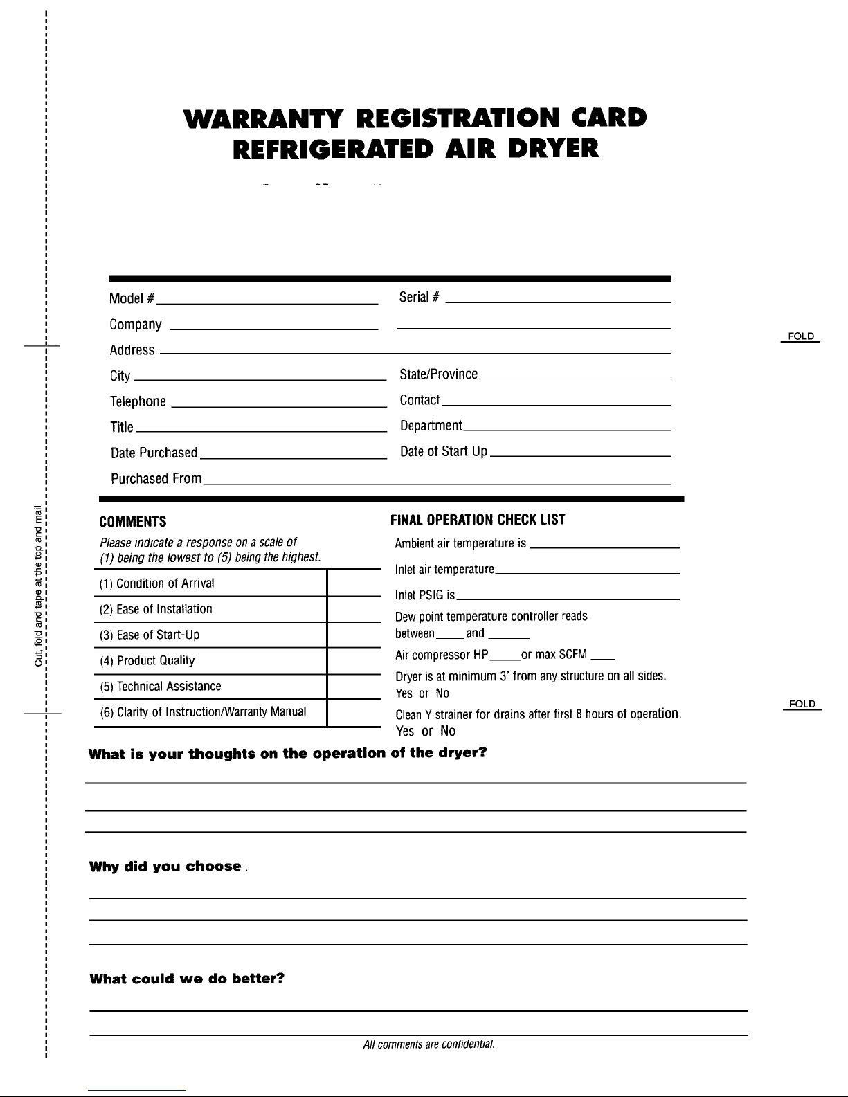
• Warranty registration
• International Warranty
• Disclaimer
• In conclusion
• Warranty registration card
(front & back)
9. Operational Controls...........16 - 36
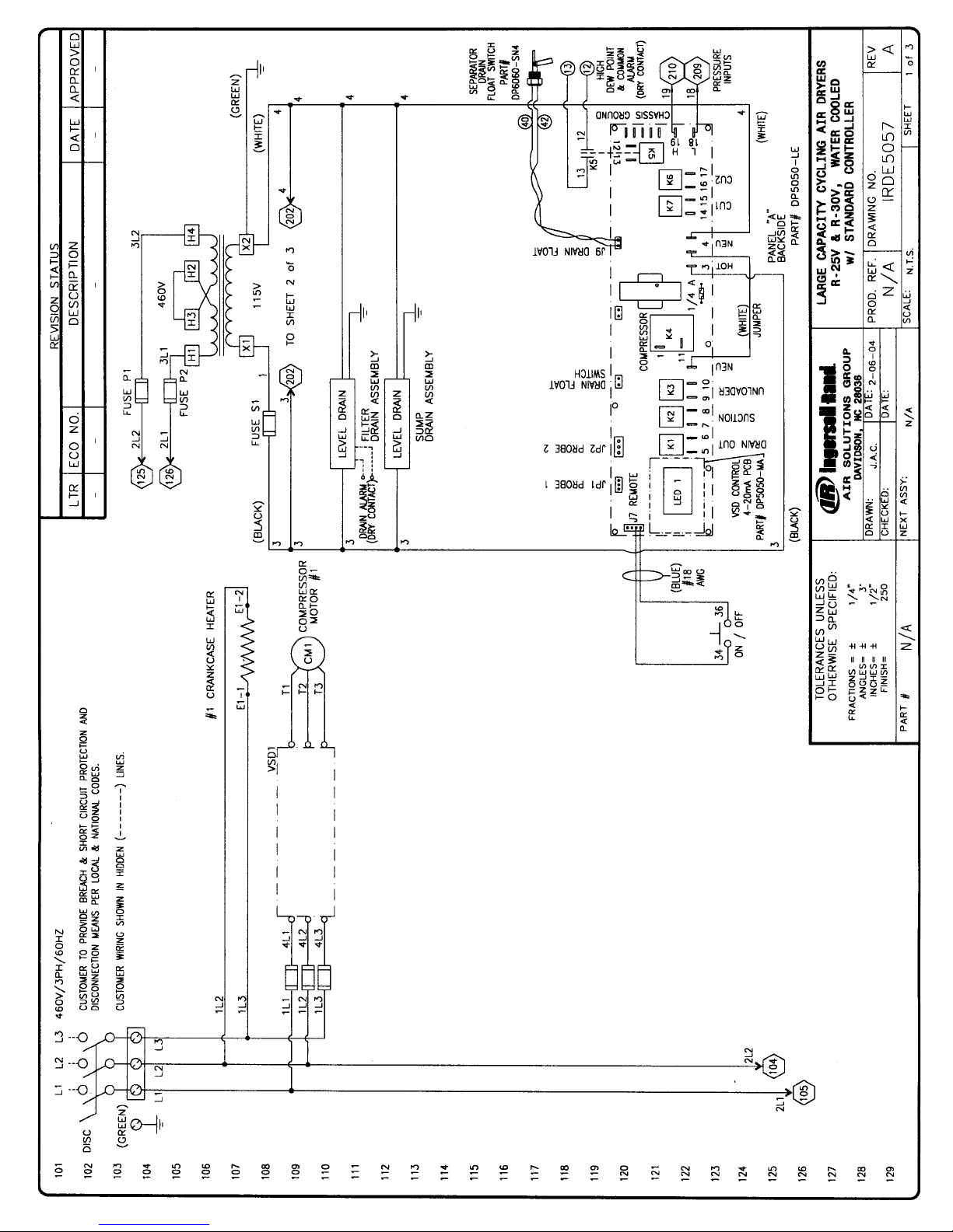
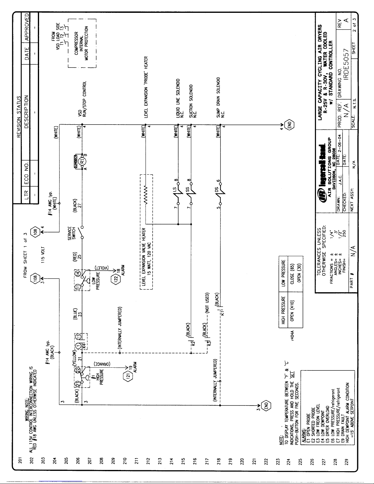
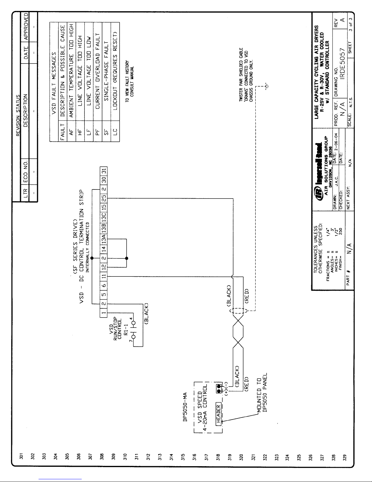
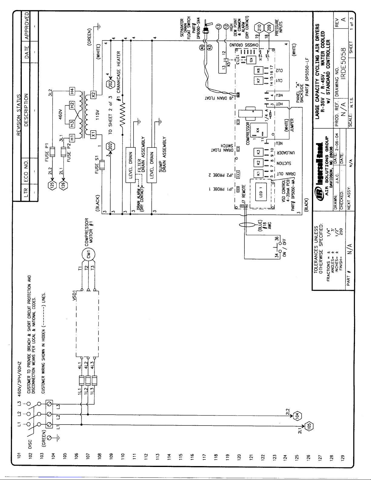
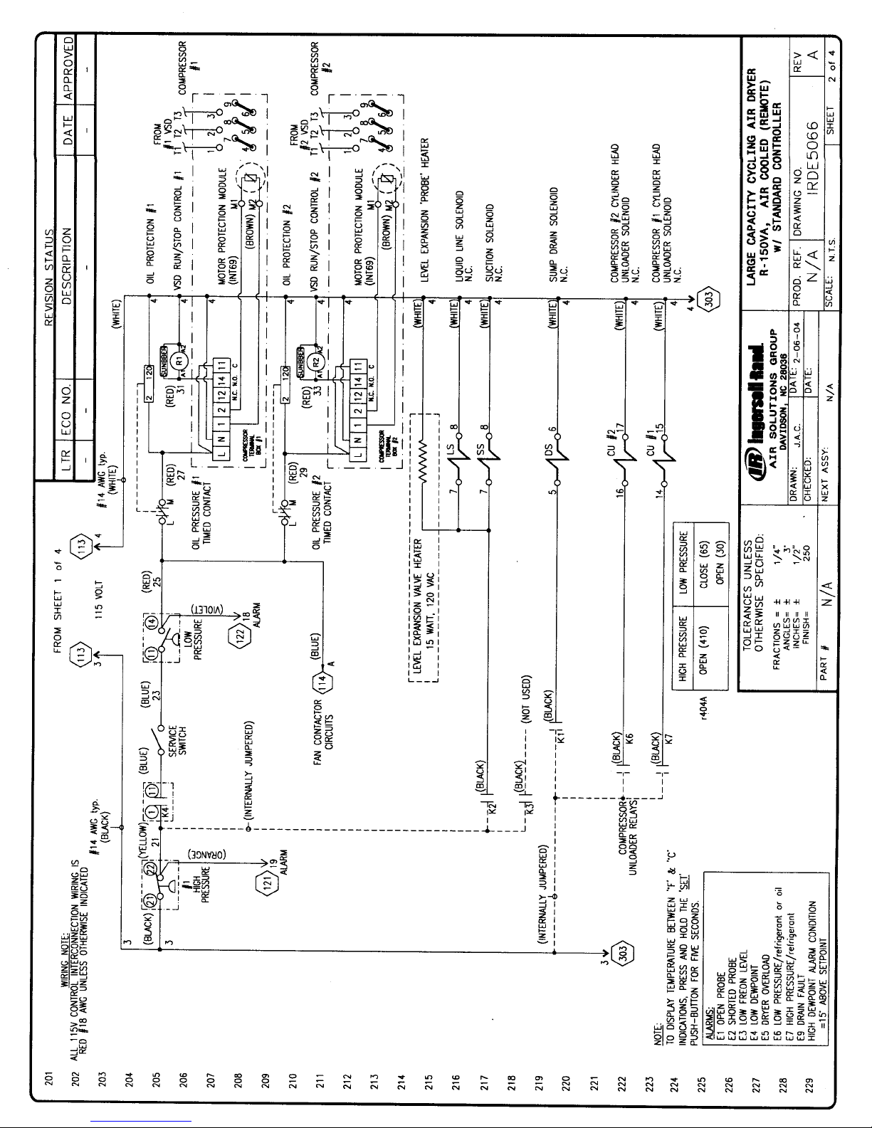
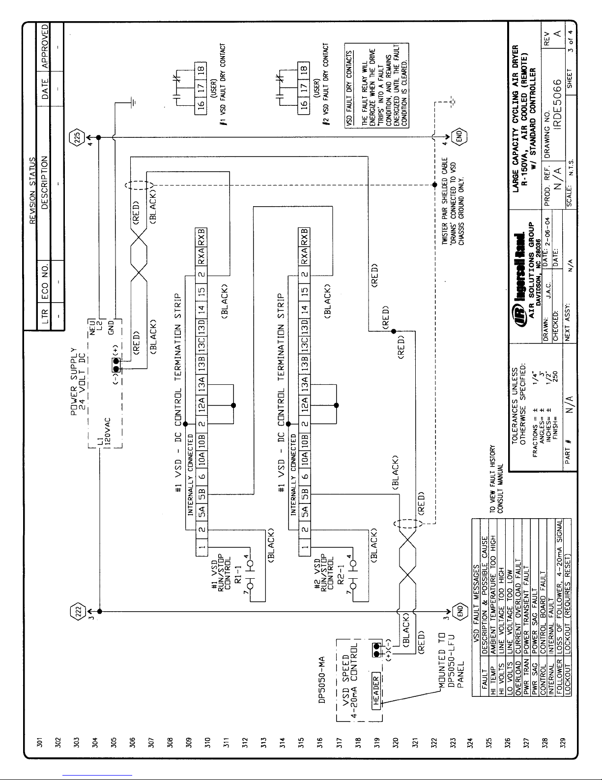
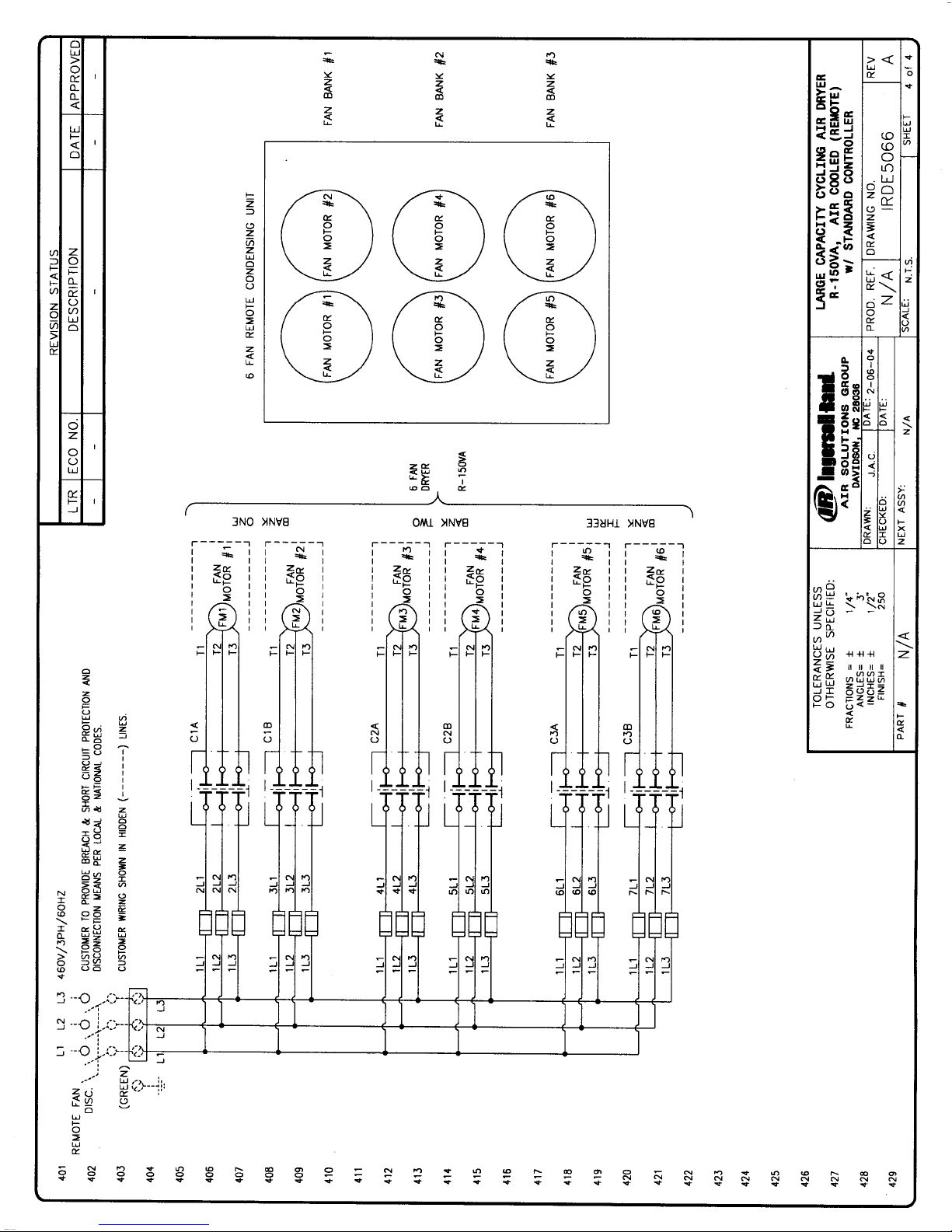
10. Electricals & Applicable
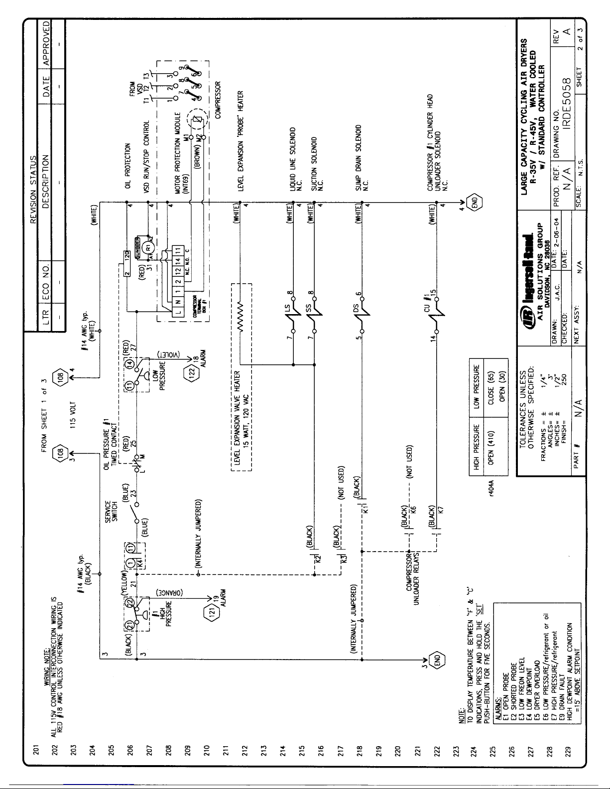
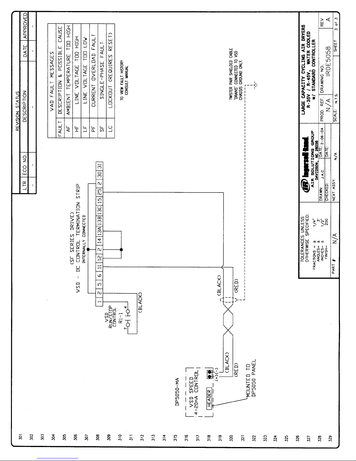
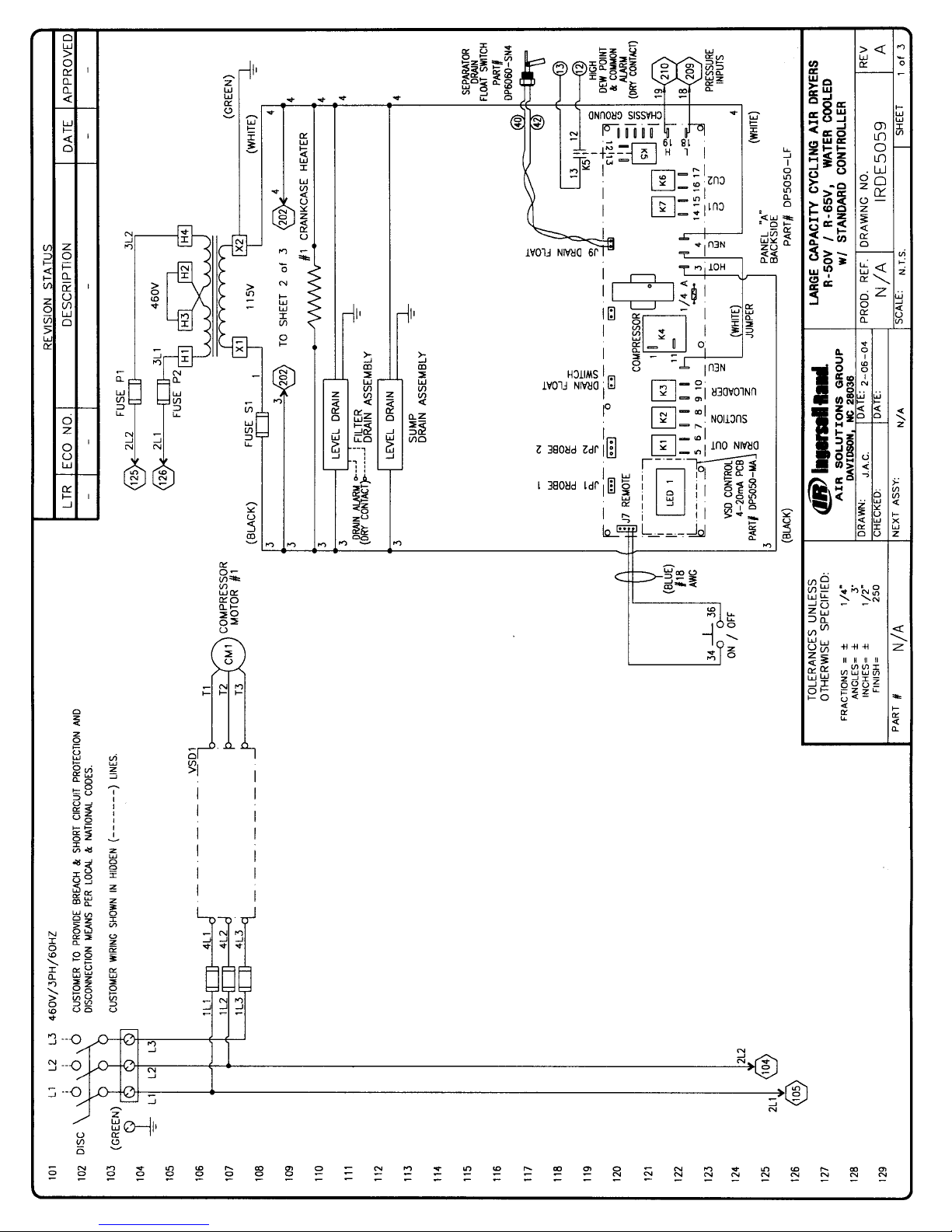
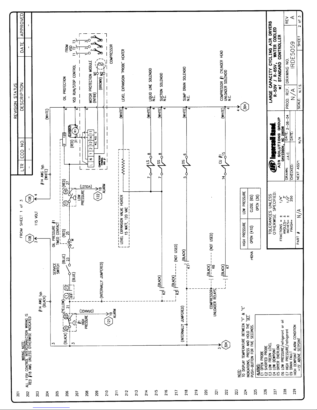
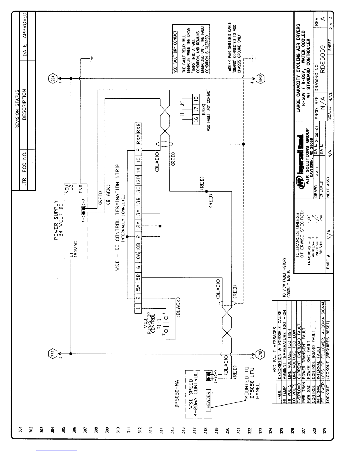
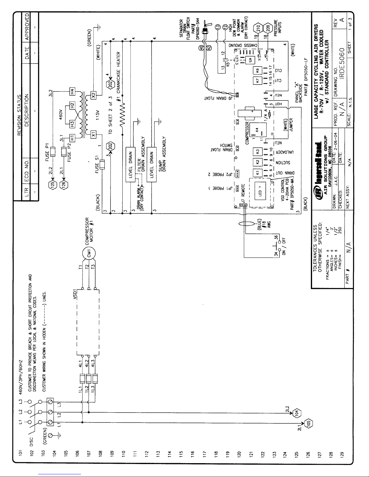
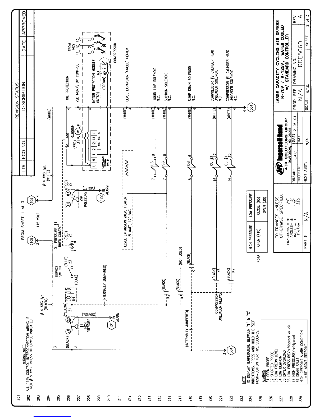
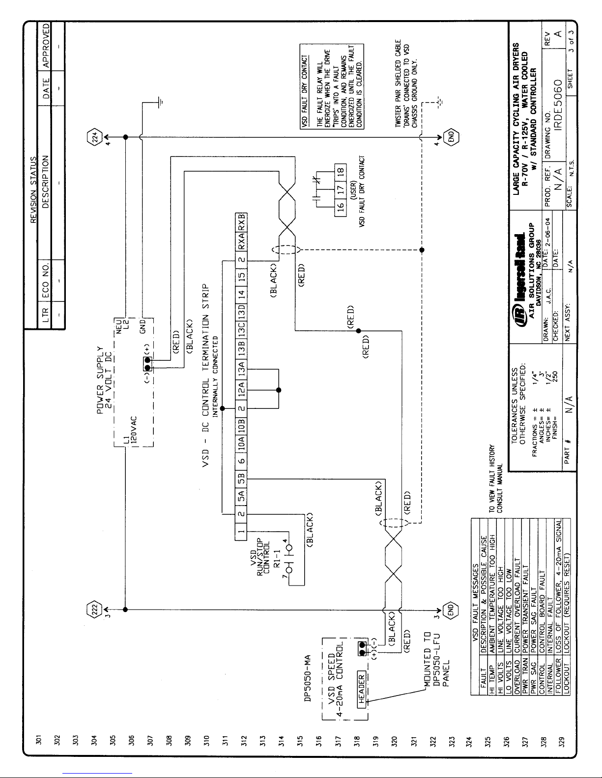
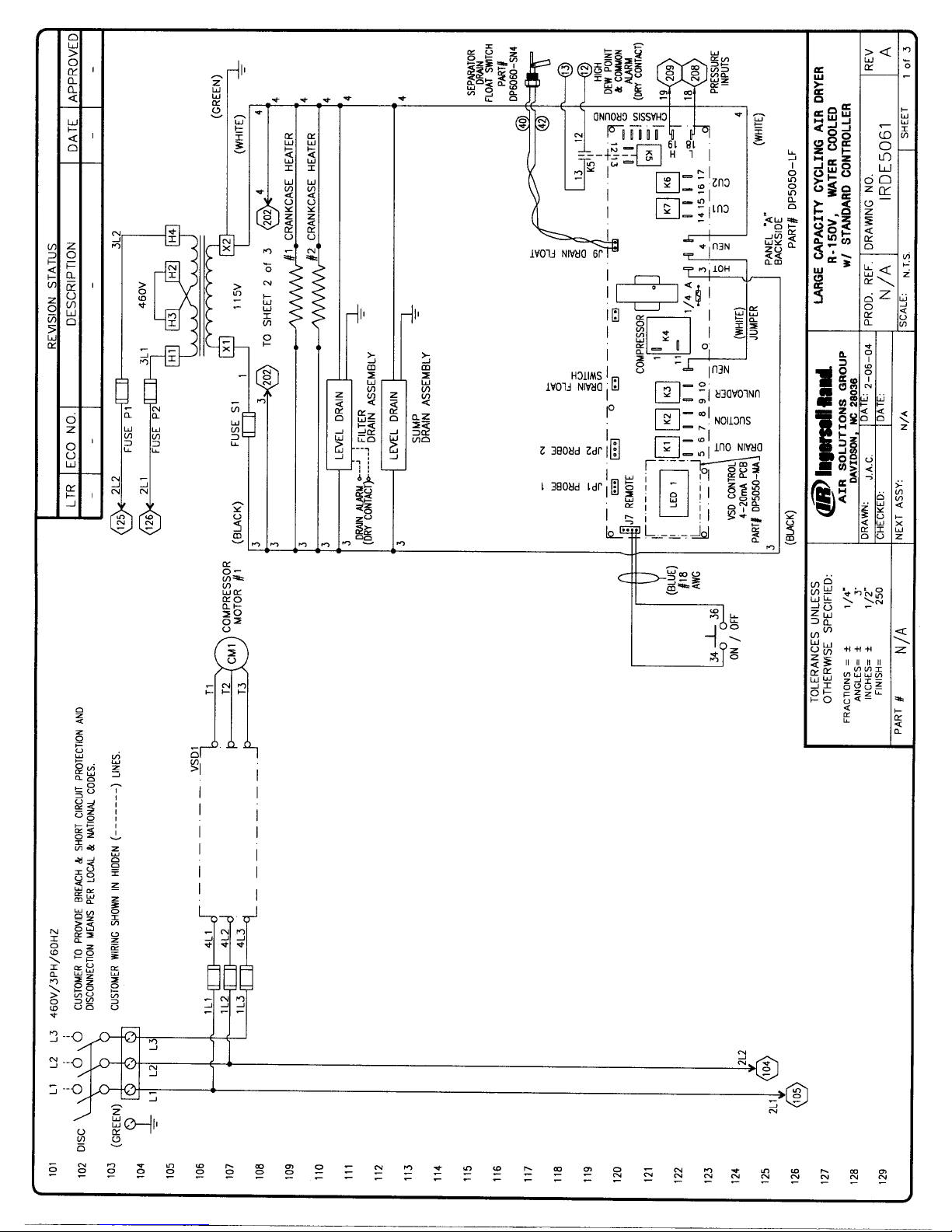
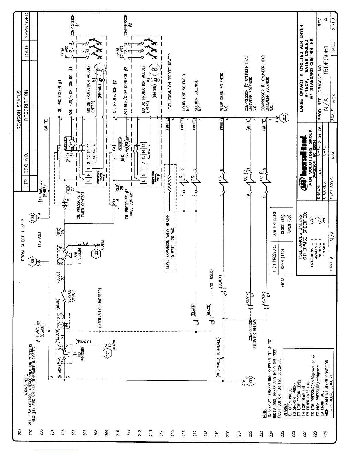
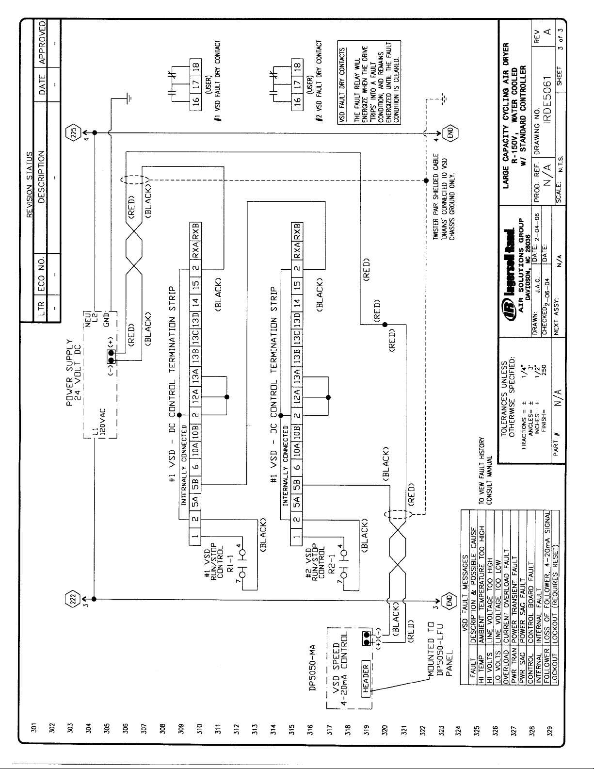
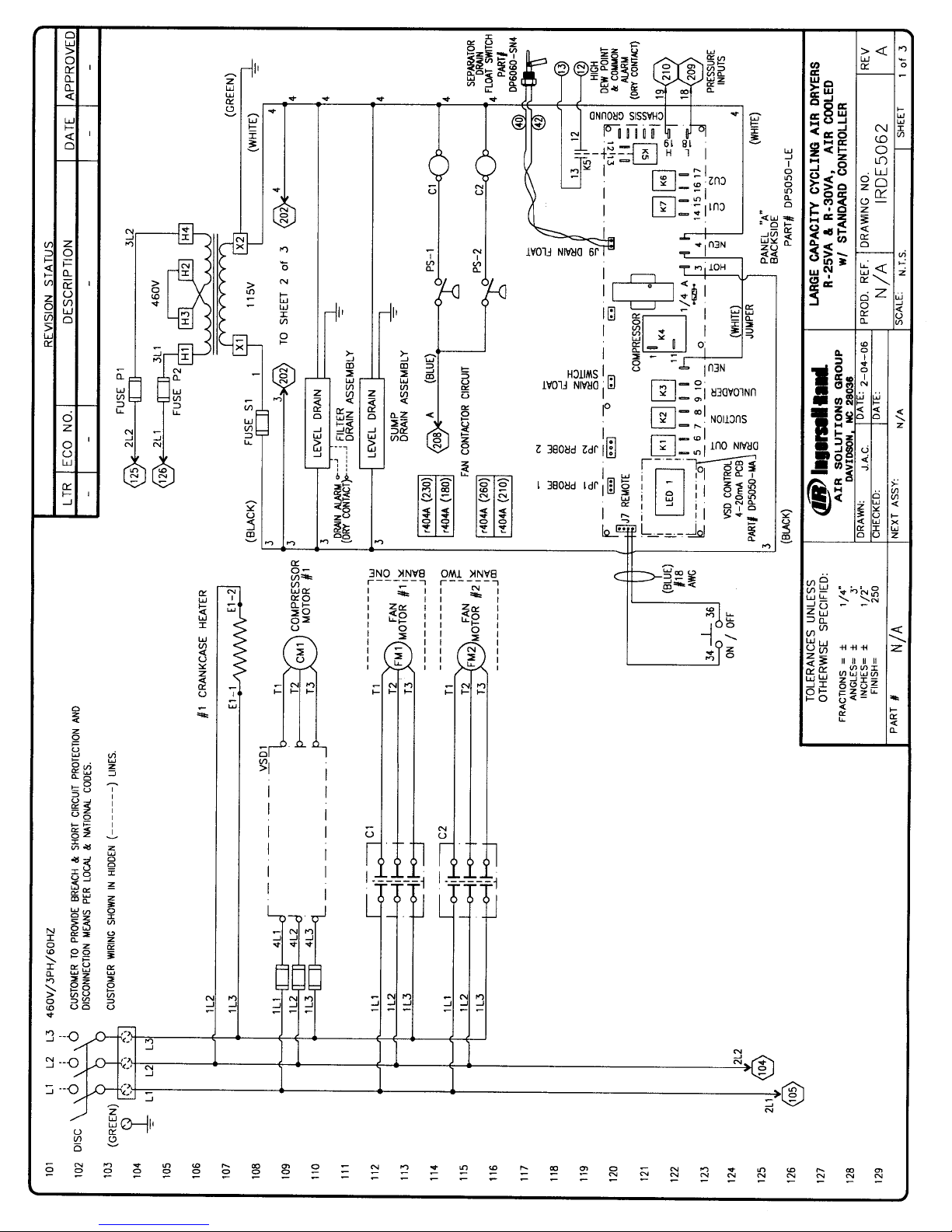
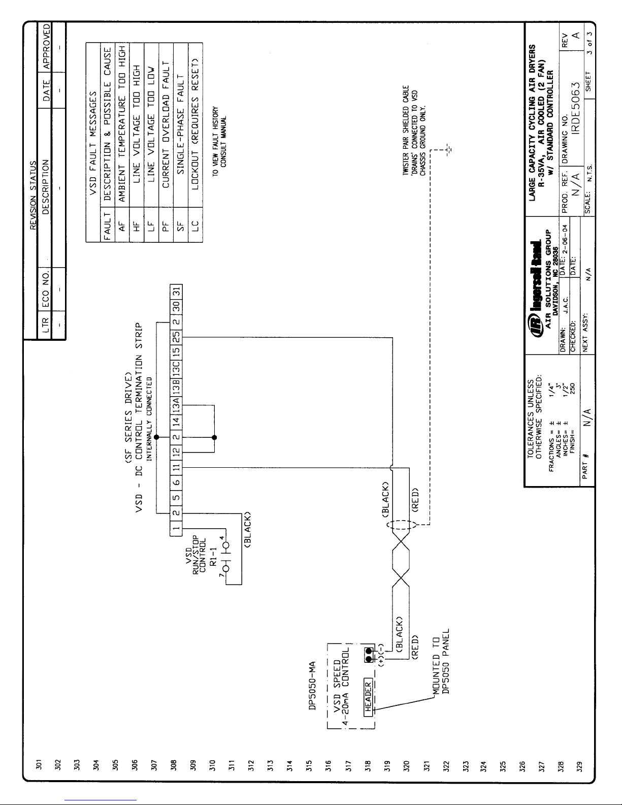
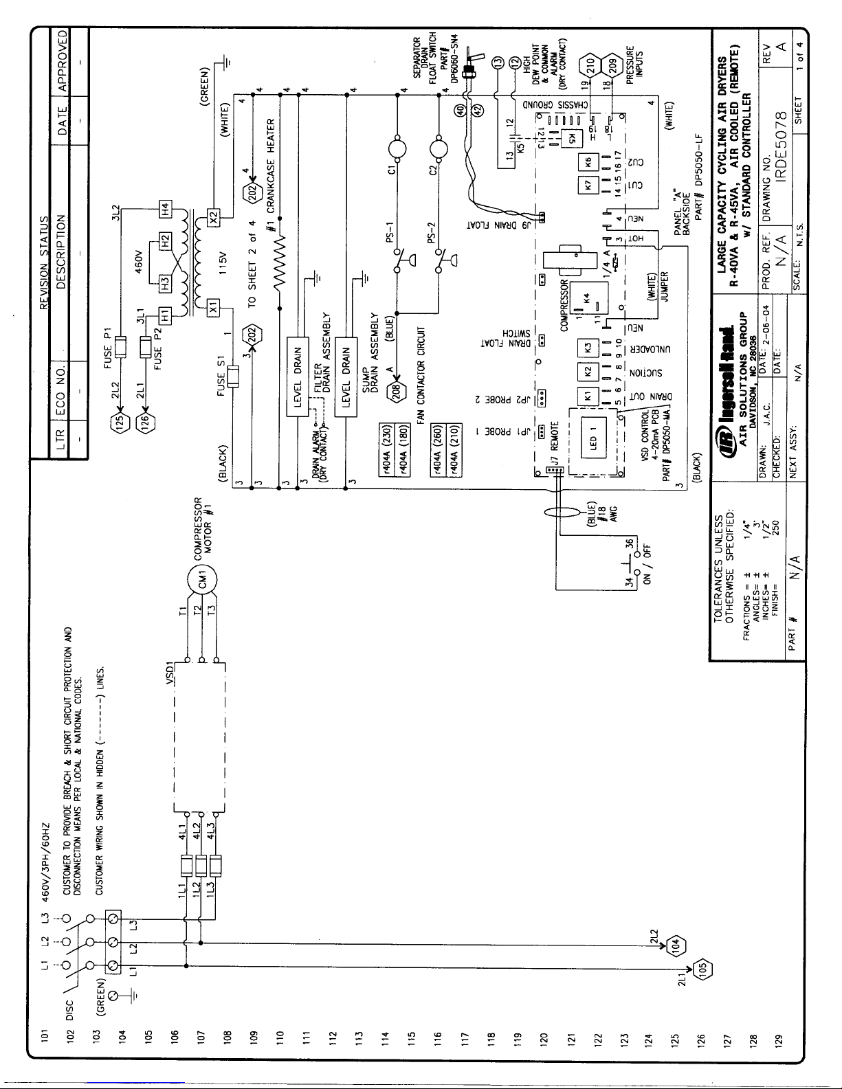
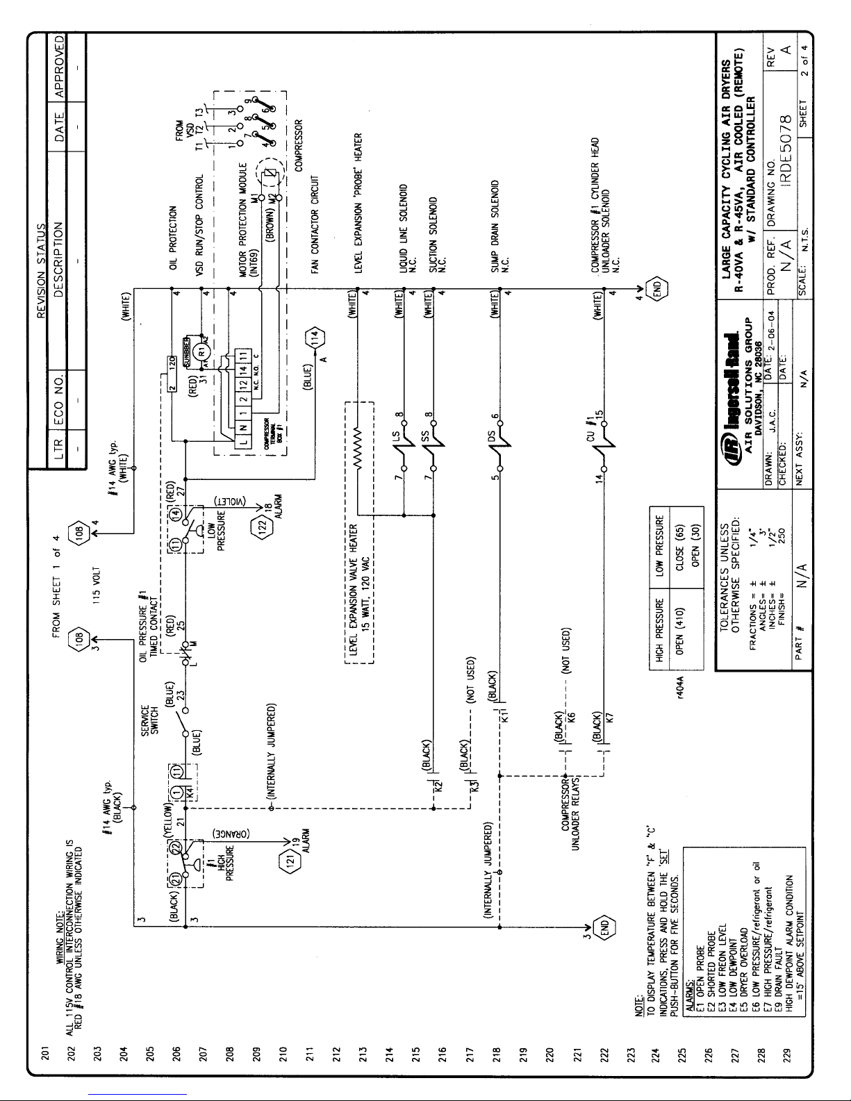
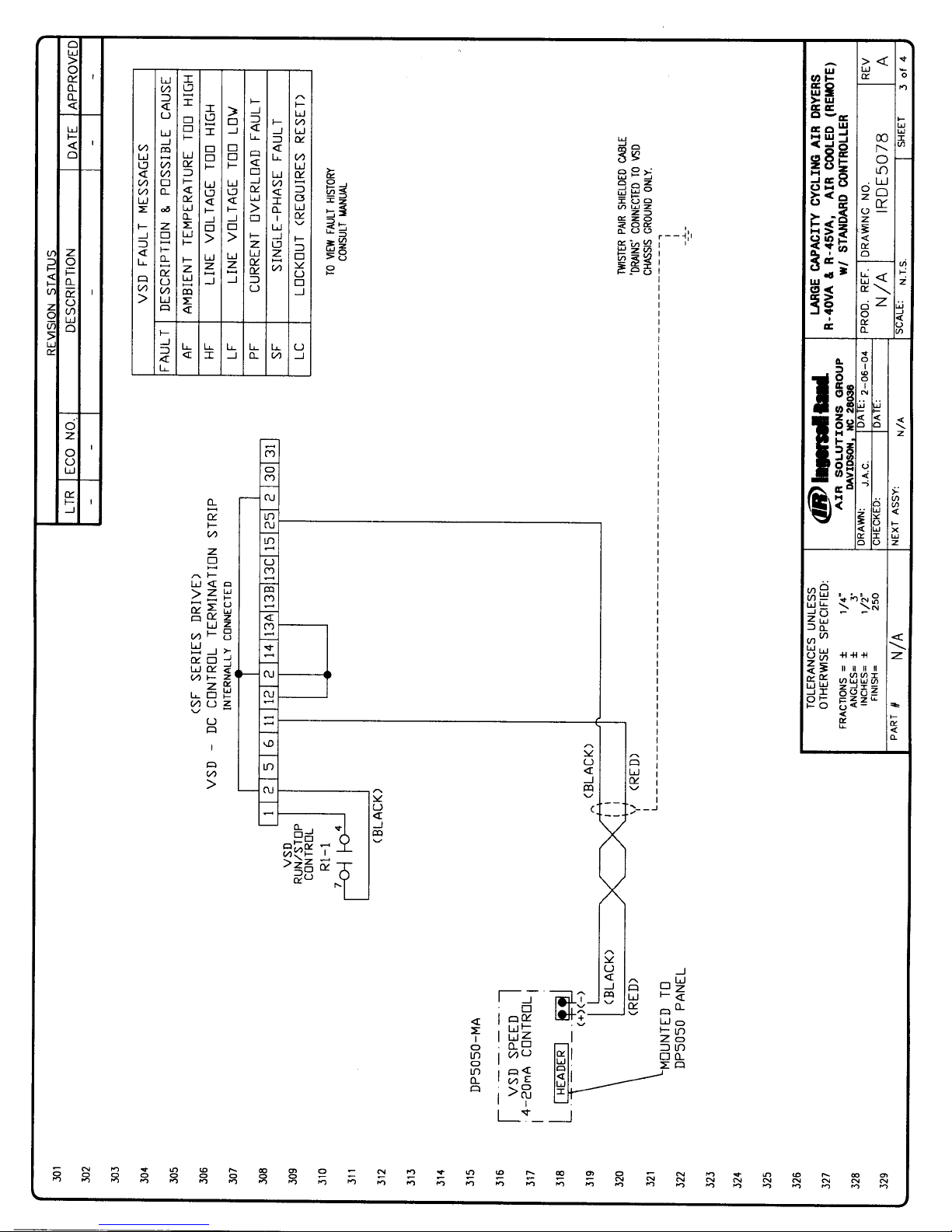
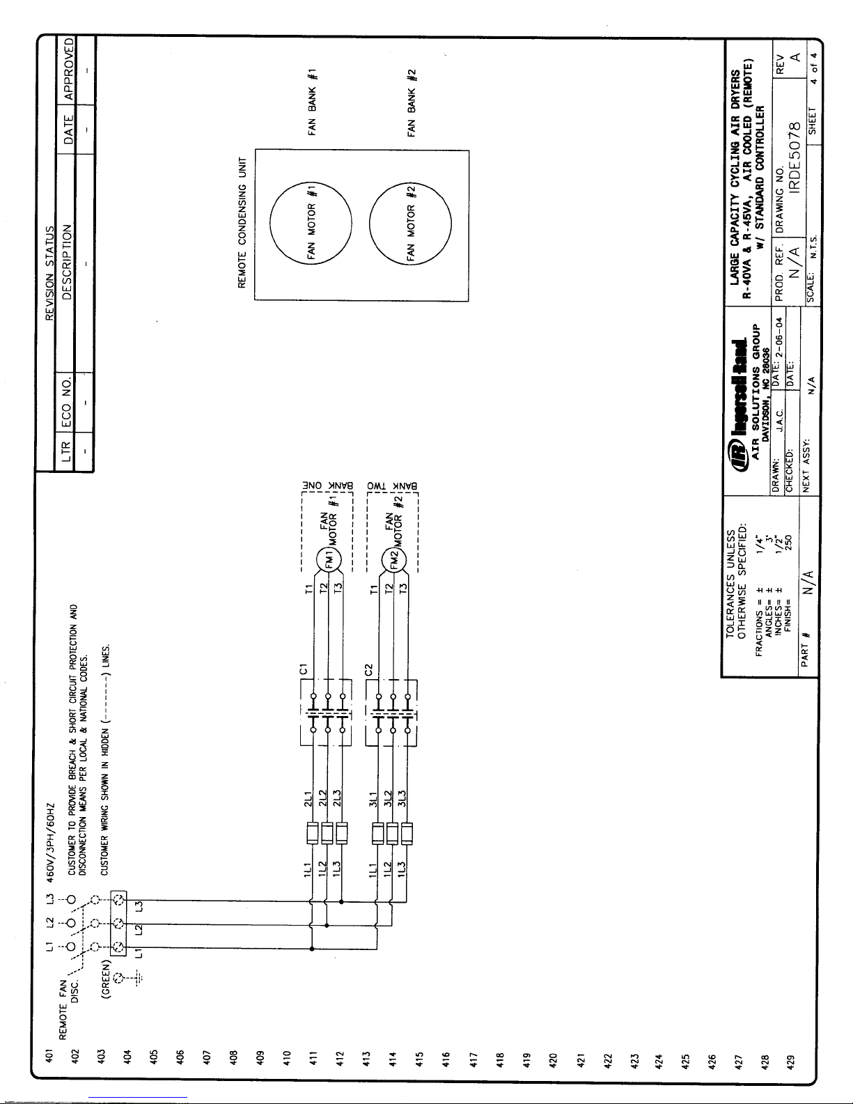
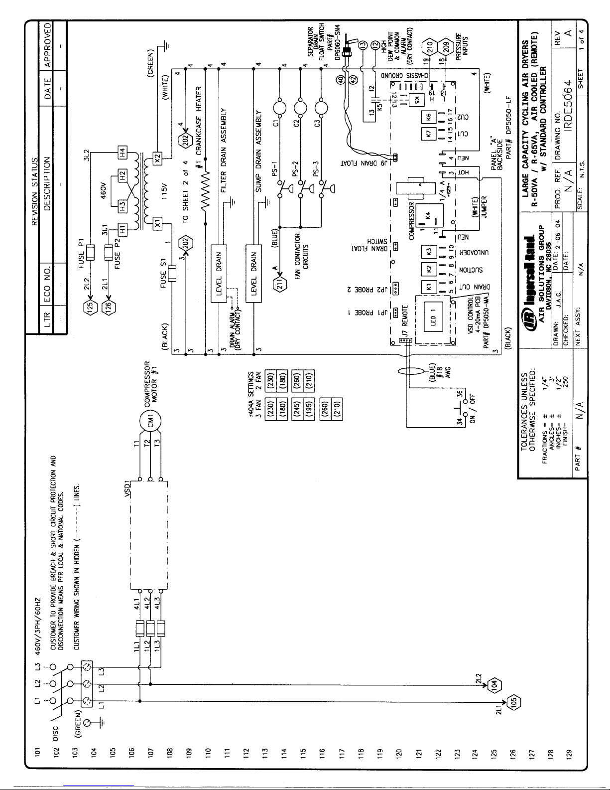
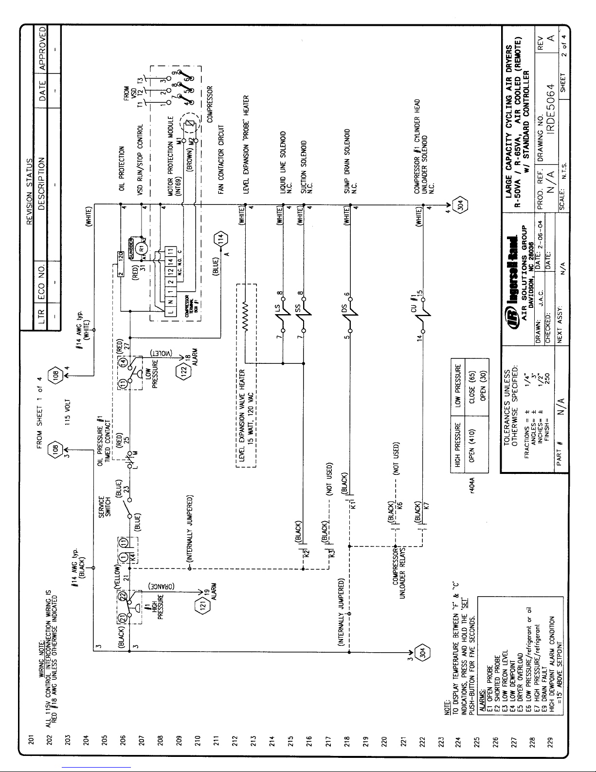
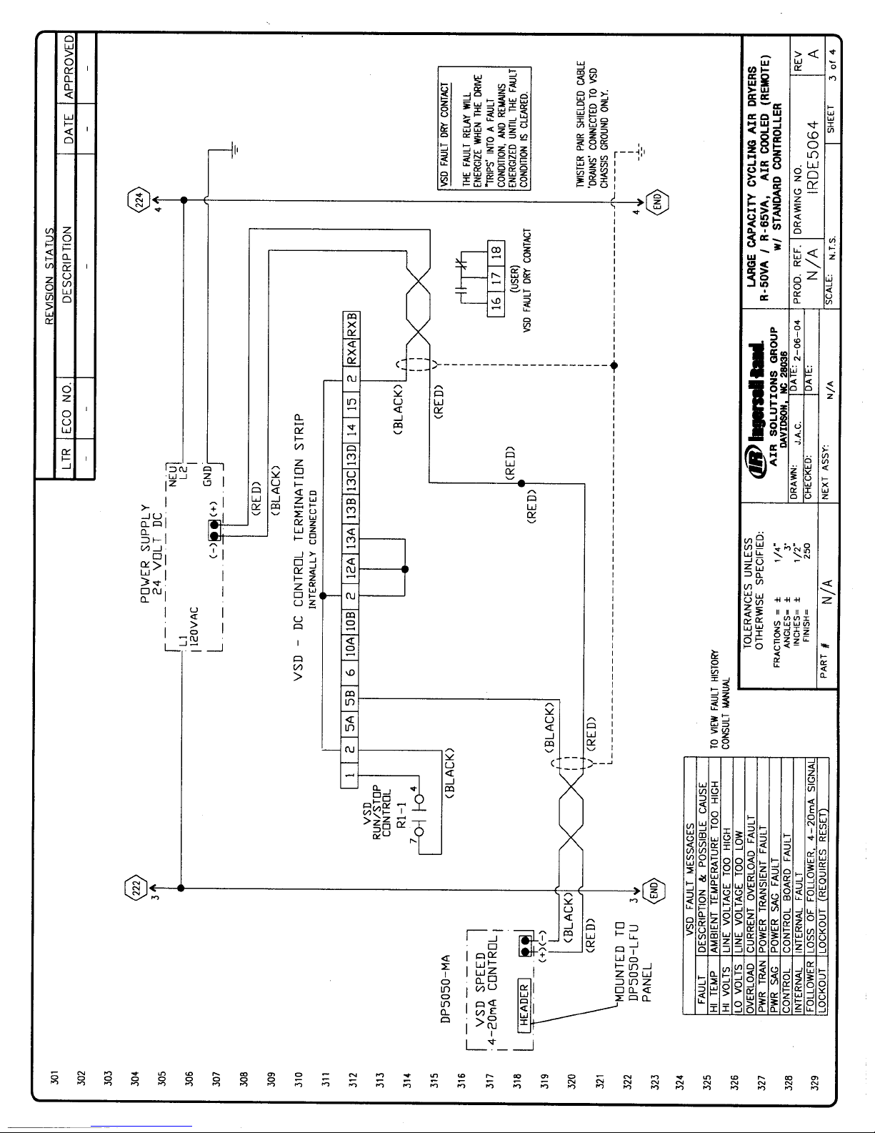
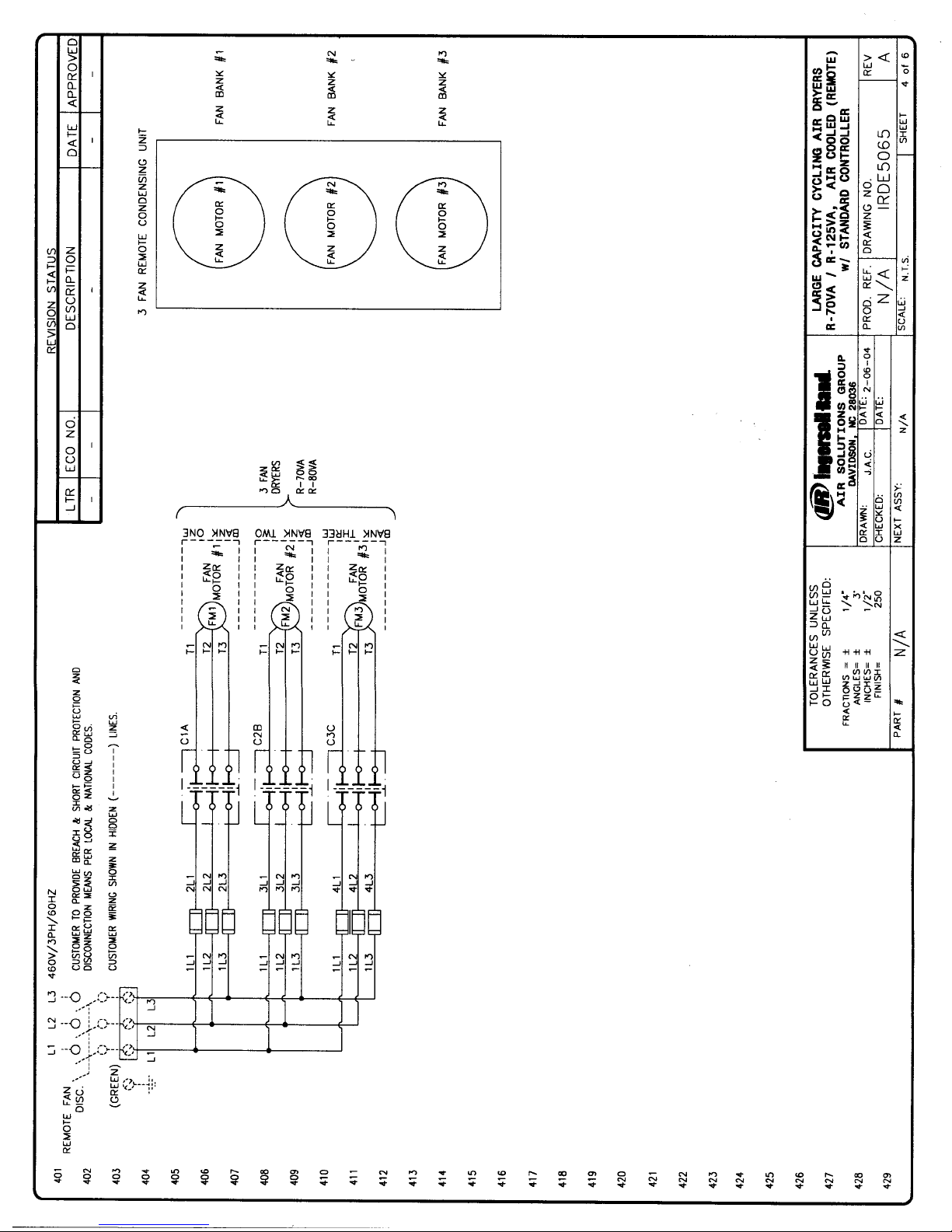
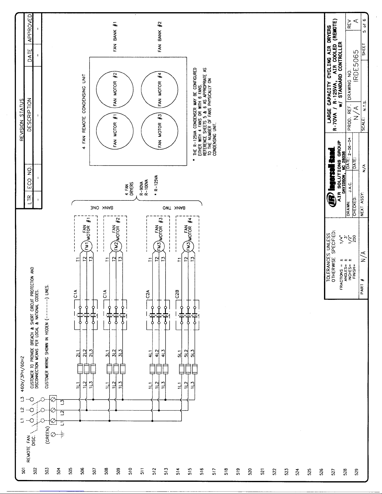
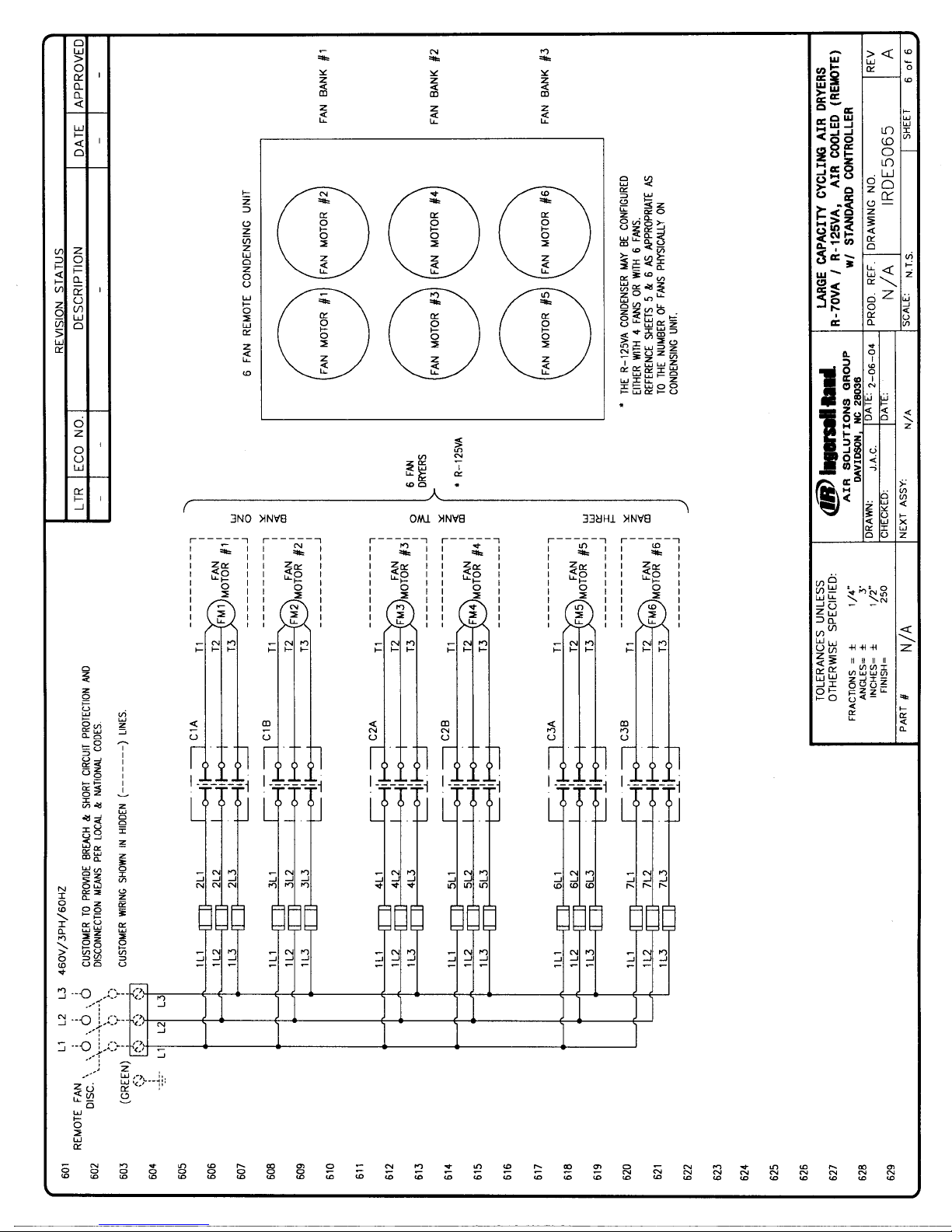
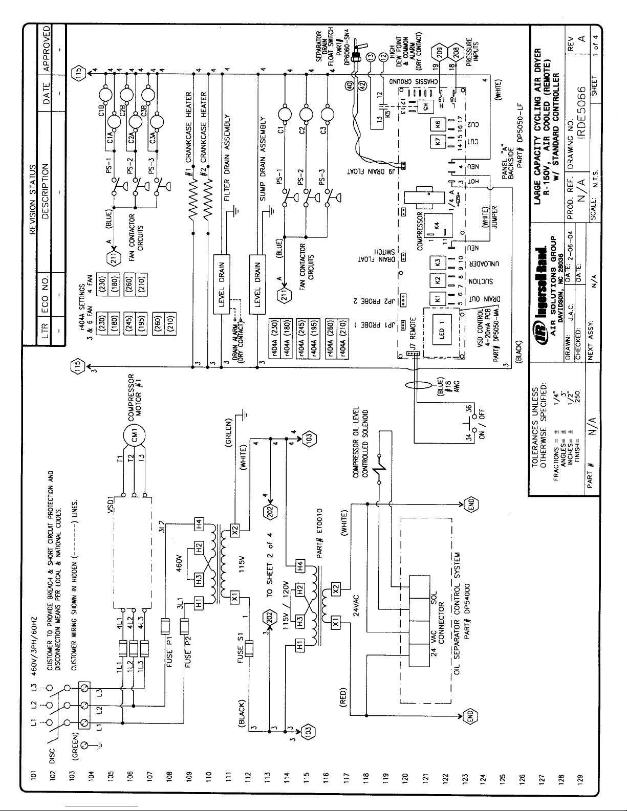
Drawings.............................37 - 75
• Water Cooled
• Air Cooled
Page 4
4
1. PRE-INSTALLATION
Inspection, Handling and Setup
Inspect the dryer carefully upon arrival and note any
damage on the freight bill. File a notice of concealed
damage if: (1) there are any dents in the cabinet; (2) the air
and drain pipes are not straight; (3) there is any sign of oil
on the skid floor. File these claims with the carrier
immediately!
Cautions and Operating Warnings
• Never work on unit under air pressure.
• Never work on unit when power is connected.
• Do not over pressurize unit.
• Install unit in a clean, cool (50º - 85ºF); well lighted
location.
• Do not shut unit off at disconnect switch except during
servicing. Unit must be turned on and off by the panel
switch located on the dryer.
• Do not pass air through the dryer while the dryer is in
the “OFF” position.
• Do not operate dryer at abnormal conditions (high flow,
high inlet temperature, high ambient, high inlet pressure, etc.)
2. DRYER INSTALLATION
Location of Dryer
Unless supplied for special conditions, the air cooled
dryers must be located in an area with an ambient temperature between 50º and 100ºF., and free from explosive
and corrosive fumes. High ambient temperatures affect the
outlet dew point of the dryer. For every 10ºF of ambient
temperature over 100ºF, a decrease of 6% of dryer performance is encountered with air cooled dryers. The unit
must not operate in an ambient of over 100ºF. For ambient
conditions of over 100ºF, water cooled dryers are suggested and are available upon request.
CAUTION – Three feet of space must be allowed between
all open grills and walls or other objects. If the dryer is
installed in a confined area, an exhaust system must be
provided to avoid excessive recirculation of hot room air.
Air line Plumbing
All connections are made to the outside of the cabinet as
follows:
• Air plumbing must be supported independently of the
dryer.
• If vibration is present, flexible metal hoses must be
installed to prevent it from being transmitted to the dryer.
• Use unions or flange joints.
• Bypass piping around the dryer is recommended for
ease in servicing or removal of unit if necessary.
• Direction of flow through the dryer must be observed. A
check valve on the outlet of the dryer to prevent back flow
and false loading is recommended.
NOTE: Use two wrenches when connecting to dryer piping
so as to prevent damage to internal air or water lines.
Water Line Piping (Water Cooled Units)
On water cooled units, install a strainer ahead of the water
inlet. Dryers are designed for 85ºF inlet water temperature.
Higher water temperature reduces dryer capacity. Minimum
water pressure is 25 psi. Maximum water pressure is 105
psi.
Electrical Connections
Before connecting electrical power to the dryer:
• Check for correct voltage and phase at electrical connection box.
• Install a fused disconnect switch near the dryer.
• Connect power to the stripped leads located in the
electrical connection box or to main lugs of contactor,
whichever is necessary.
(NOTE: All units must be externally grounded to protect
against the possibility of severe electrical shock.)
• CAUTION: Wire the dryer separately from the air
compressor. The dryer must NOT cycle on and off with
the air compressor.
• Phase rotation is only important if the dryer has a 3
phase condenser fan. Fans must PULL air through the
condenser coil.
• Crankcase heaters are pre-wired at the factory to the
line side of the terminal box or contractor. Heaters must
be energized at all times, therefore the main disconnect
must be left on except when servicing the dryer.
3. PRINCIPLE OF OPERATION
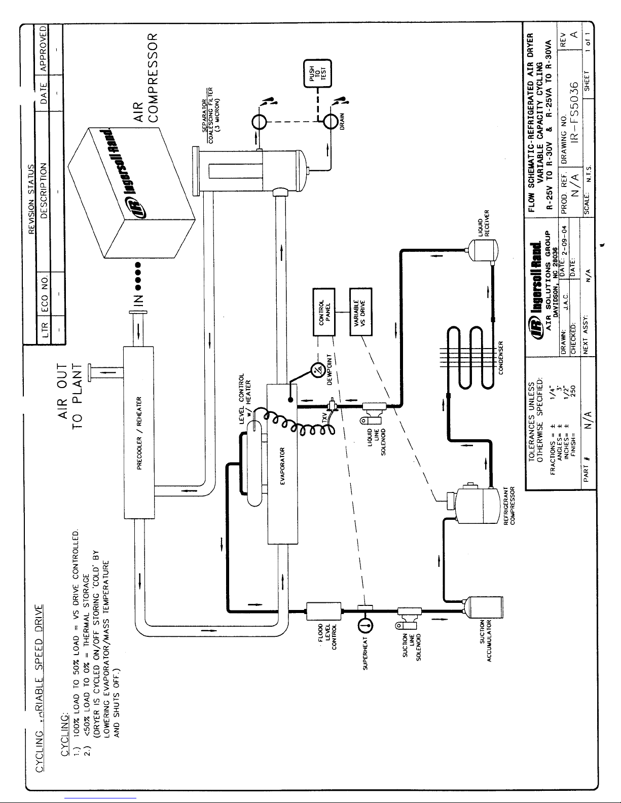
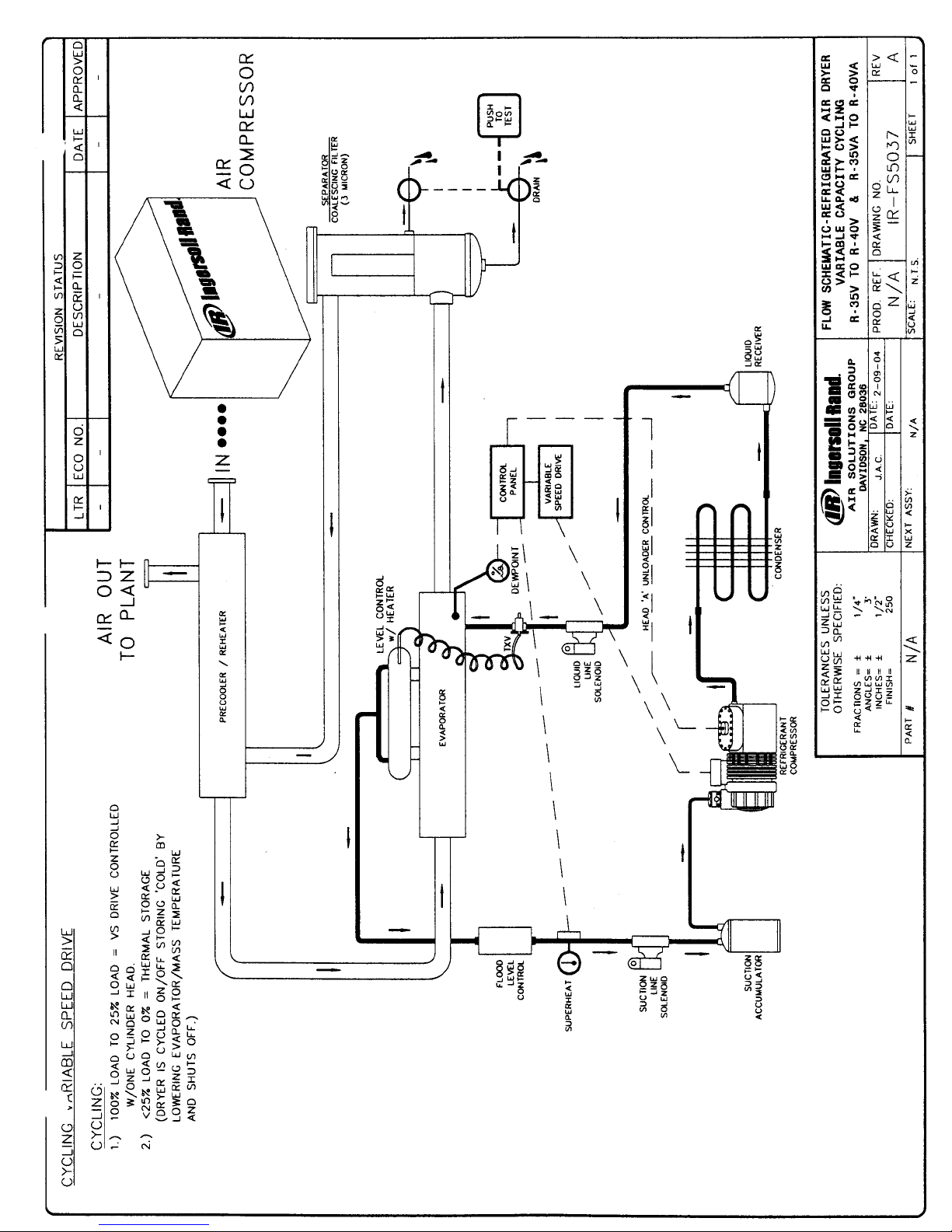
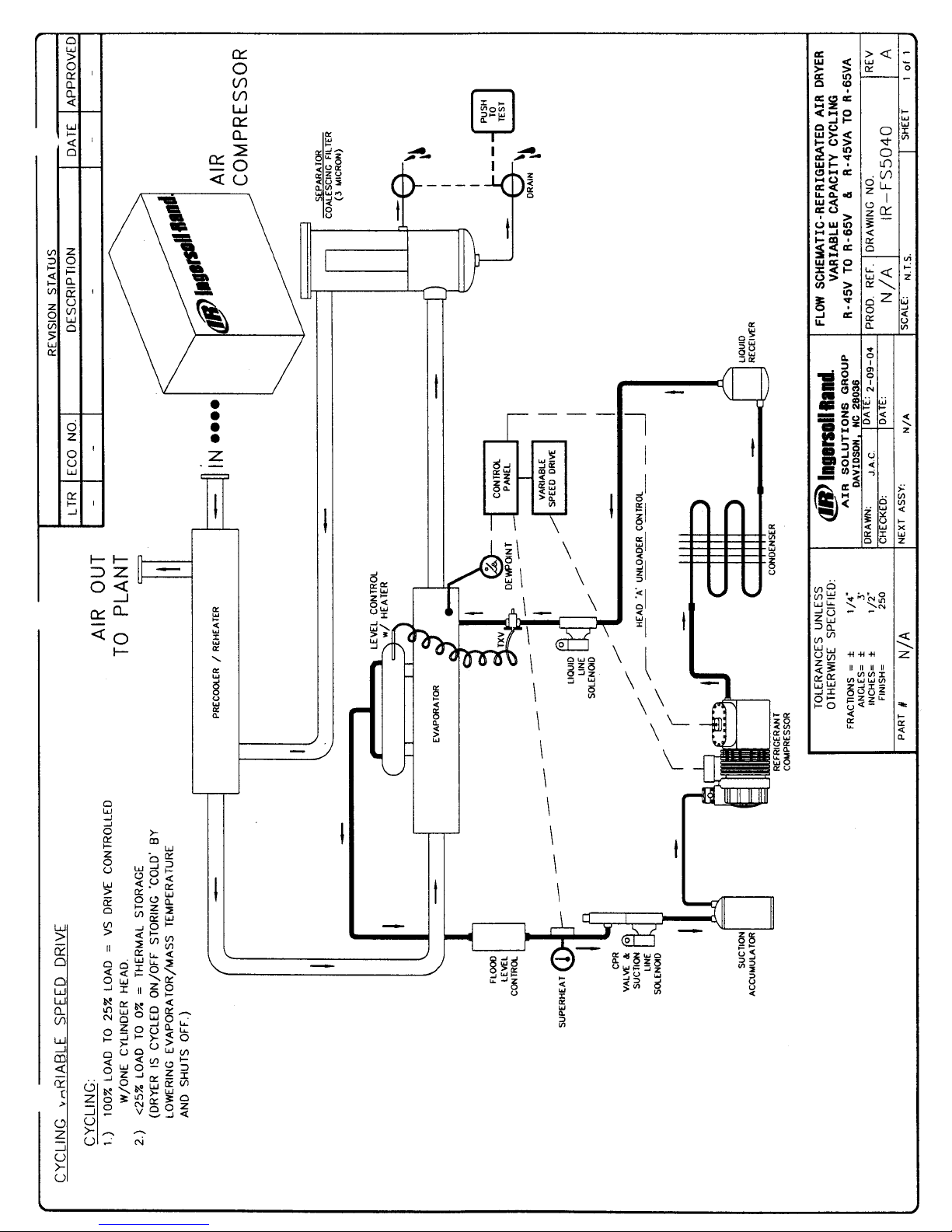
The VCD REFRIGERATED AIR DRYER is designed to
operate automatically and continuously from no load to full
load without freeze up.
Air System:
The major air system components are the air to air
PRECOOLER / REHEATER, the EVAPORATOR, and the
MECHANICAL SEPARATOR.
Hot, wet air enters the inlet of the precooler/reheater where it
is cooled by the outgoing air. The air then enters the
evaporator where it is cooled by the refrigerant causing the
air’s humidity to condense into liquid water.
Next the air travels to the separator. First, the air enters the
separator where bulk oil and moisture are removed from the
air stream through a combination of centrifugal action and
velocity reduction. After removal from the air stream, all
contaminants are ejected from the air system by Demand
Control Solenoid Drains.
From the separator, the cold dry air enters the outgoing side
of the precooler/reheater where it is reheated by the hot
incoming air.
The precooler/reheater serves a triple purpose. By precooling the incoming air, it conserves refrigeration use and by
Page 5
5
reheating the outgoing air, it serves to eliminate sweating of
pipes in the plant air system. Most important, it increases
the temperature dew point split, preventing moisture from
condensing out of the compressed air when the air is
expanded.
Refrigeration System
The major components of this system are the COMPRESSOR, the CONDENSER, and the EVAPORATOR. The
compressor pumps high pressure, high temperature gas to
the condenser. The heat is dissipated through finned tubes
with the assistance of motor driven fans. On water cooled
units the heat is dissipated through a water filled tube and
shell condenser.
During the cooling process, the refrigerant changes from a
heat laden vapor to a liquid. This liquid refrigerant flows from
the condenser to the filter dryer, and then through the sight
glass which indicates refrigerant level. Immediately before
the inlet of the evaporator is a thermostatic expansion valve
which regulates the refrigerant flow to the evaporator as low
pressure cold liquid. The cold refrigerant cools the air in the
side of the evaporator. As the low pressure liquid refrigerant
absorbs the heat from the air it boils and changes to a
vapor. This low pressure, low temperature vapor is then
returned to the refrigerant compressor where it is again
compressed to a high pressure, high temperature gas, and
the refrigeration cycle repeats itself.
VCD Dryers are rated to deliver full capacity (SCFM at 35ºF
pressure dew point air) at 100 PSI line pressure, 100ºF.
inlet air, in 50º to 100ºF ambient, at 2 to 4 PSI pressure
drop. Higher line pressures, up to rated maximum and
cooler inlet air increases capacity. Free liquid water, low
pressures, higher air temperatures and condensable
chemical vapors, decrease capacity. Consult the factory for
proper dryer sizing.
5. START UP
NOTE: Please read and understand the entire operation and
maintenance manual prior to starting the dryer. This is a
brief start up procedure for those familiar with dryer operation.
CAUTION: There should be no air flow through the dryer
before or during start up. It is recommended that the dryer
be installed with bypass piping to better service the unit.
DRYER START UP PROCEDURE:
1) Make main electrical connection to dryer and apply
power. Refer to dryer name plate or manual to determine correct voltage. Leave power on unit for 8 hours
before proceeding.
2) On water cooled units make sure there is proper water
pressure and temperature supplied to the water condenser. (Min 25 psi and max 85º F water temperature)
3) Dryers are shipped with
TAGGED refrigeration service
valves closed. TAGGED service valves must not be
opened until main power is permanently applied.
However, ONLY TAGGED service valves must be
opened prior to start up.
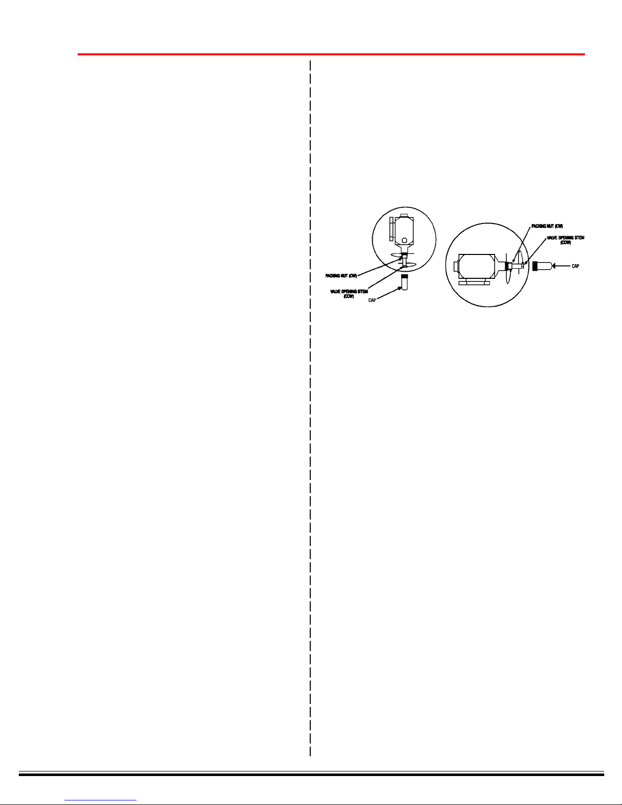
• Locate TAGGED service valves.
• Remove protective cap from valve stem. (see figure
below)
• Using a refrigeration service wrench or small crescent
wrench, turn the valve stem counterclockwise until it
stops. Occasionally it may be necessary to retighten
the packing nut (clockwise) if a leak is observed. The
valve will now be fully open.
• Replace cap.
• In case of refrigeration ball valves, you must turn 90
degrees to open as stated on valve. (See figure below)
4) Locate the compressor service toggle switch. This
service switch must be turned on immediately after
valves are opened.
· The refrigeration compressor may run briefly and then
stop. This process is called pump down. If storage
conditions were adverse, the compressor may make a
loud metallic hammering noise. If this happens, turn the
service switch off and wait half a minute, then turn back
on. Repeat this step until the compressor runs
smoothly, then stops. Leave the service switch in the
ON position.
5) The dryer is now ready to run. Turn the dryer on at the
control panel.
The digital display should start dropping.
6) With the dryer turned ON from the control panel and
cycling several times, you may now introduce compressed air to the dryer. Open the inlet and outlet
ISOLATION VALVES. Close the BYPASS VALVE.
7) Check automatic drain for proper operation. Drain
should open at regular intervals based on the drain
control settings or water level.
8) Restart dryer using this procedure after maintenance,
power failure or after prolonged shutdown periods.
CAUTION: Failure to follow the above steps in the order
shown MAY result in damage to equipment NOT covered
under warranty.
Operating Instructions:
Always:
• Turn dryer ON and OFF with control panel button.
Keep power to unit during off cycles.
• Start dryer and allow it to cycle several times prior
to allowing air flow through the dryer.
• Clean condenser when dirty.
• Keep ambient temperature under 100º F.
• Keep inlet temperature under 100º F.
• Check and clean Y-strainer periodically.
Page 6
Page 7
Page 8
Page 9
Page 10
10
Never:
• Turn off main power disconnect except when
servicing.
• Allow air to flow through the dryer when it is not
running.
• Cycle dryer with air compressor
5. ROUTINE MAINTENANCE AND SERVICE
Air Cooled Condenser
Very little routine care is necessary for the VCD Dryer. The
most important step for an air cooled dryer is to keep the
air cooled condenser clean. The air is being taken in
across the condenser. Dirt from the ambient air will
accumulate on the finned tubes of the condenser coil. As
the dirt will accumulate on the rear of the condenser,
blowing from the inside out is most effective. In dusty
areas the simple, inexpensive installation of a furnace filter
will stop the majority of dirt entering the dryer’s condenser.
This should be changed when visibly dirty. If the condenser
does become dirty, an abnormally high refrigeration discharge pressure will occur. The unit may shut down on
high dew point or high pressure. This will greatly reduce
the life of the refrigeration compressor and could void the
warranty.
Separator/Coalescer Drains
Drains should be checked regularly. Failure of an automatic drain can result in extreme amounts of water and
debris in your air system.
6. FOR THE REFRIGERATION SERVICE
TECHNICIAN
IR recommends that only qualified and experienced refrigeration mechanics do repair work on these units. This
section is a list of hints and instructions for the skilled
serviceman.
Recharging Dryer – Refrigerant, Oil and Dryers
Consult the IR Service Department for the required charge
needed for each unit. The relatively large charges are
needed because of the flooded-shell evaporators. Use the
following to assess the adequacy of the charge when
unsure:
• The sight-glass should stay filled most of the time
when the dryer has its customary air load. It is normal
for the glass to break up when the condenser fan starts
if the load is light or when the unit unloads. It may
take time to refill when it reloads. Don’t charge to clear
the glass with no load; that will be too much.
• All units have a charging fitting on the evaporator shell.
The unit must be charged through this fitting and/or the
liquid line service valve. The best way is to dump liquid
into both ports with the dryer off, then start up and
continue feeding a full stream of liquid into the evaporator until charged.
Do not charge vapor. You want the charge installed as
fast as possible so the oil will be returned to the compressor as in normal operation.
Additional oil is added at the factory to compensate for the
migration with the freon. If a compressor is replaced,
remove the drain plug from the evaporator shell (on steel
shells) to drain any excess oil trapped. If that isn’t possible, it may be necessary to remove oil from the system
after start-up. Excess oil is indicated by noisy and vibrating compressor operation. Consult factory for recommended oil changes. Prolonged operation with insufficient
charge or a bad TXV may cause oil to be trapped in the
evaporator. If the compressor is still good, this oil will
return within a few minutes of operation with the correct
conditions. For R-404 & R-134 applications use synthetic
refrigeration oil.
Please replace both suction and liquid filter-dryers together
whenever the system has been exposed to air or water,
unless it’s brand new or you know how much gas has gone
through it. Solids will be caught in the suction drier even if
the system is dry.
Evaporator Leaks
If there is a leak between the tube and shell side of the
evaporator, the usual symptom is high head pressure,
because the air pressure is higher than the refrigerant
pressure.
To determine this, bypass airflow, stop dryer, and observe
head pressure after it stabilizes. 20 minutes is sufficient. If
the pressure is much higher than that corresponding to the
ambient temperature, there is air in the system. Purge air
at compressor discharge or receiver inlet to verify.
Gross leak-checking of the evaporator is done at the
separator drain with air pressure off and at least an hour
wait. If a leak is verified, it can often be fixed by removing
the bonnets, locating the leak with bubble soap and rerolling the leaky tubes. Split evaporator tubes can be
plugged with special tapered brass plugs.
WARNING: If the refrigerant has been seriously contaminated with water you probably won’t be able to dry it with
dryers or vacuum. Do a solvent cleanup on the evaporator
and suction accumulator or replace the evaporator.
Refrigerant Control Valves
Expansion valves: The superheat (+15º F) that the valve
control’s is created in the control evaporator or suction line
heat exchanger. There is liquid or zero superheat at the
main evaporator outlet to facilitate oil return and keep the
shell flooded. If there is superheat at the main evaporator
outlet or if the suction line to the compressor is warm to the
hand, 1) check the charge. If the sight-glass is full, 2) the
TXV may be defective or the liquid line is blocked. The TXV
superheat adjustment is not critical.
IR uses standard type valves.
• Don’t use any TCLE Alco valves. TCLE valves are too
slow.
• Use cross-ambient “C” or liquid “L” charges. Do not
use any pressure limiting or all-purpose “W” charges.
Page 11
11
• We recommend that you increase the superheat setting
of the new valve about 5º F from the factory setting.
Turning the stem 2 turns in should be sufficient.
• Position the sensing bulb of the new valve just where
the old one was. It is crucial that the suction line be
clean and the bulb well insulated.
Solenoid Valves: The suction solenoid valve rarely causes
any trouble because the pressure difference across it is
never great. Unloader solenoids operate with greater
differentials. The VCD Dryer uses valves with a rated life of
more than two million operations. When they finally wear
out, the usual symptom is failure to close. The valves can
usually be restored by installing a diaphragm repair kit
available from IR.
Drains
The draining of water from the separator is the most crucial
part of the whole process. A complaint of “there’s more
water in the air now than there was before the dryer was
installed” is usually a drain problem.
The VCD Dryer has a demand operated drain. Operate the
drain manually and be sure that air blows out of the drain
line. Clean the strainer and solenoid valve if not.
The MRD demand Drain has a SINGLE point hermetically
sealed float switch. This extremely simple mechanism
resists fouling and wear.
2) Water freezes in the evaporator causing air pressure
drop.
3) There is erratic or out-of-range indication of dew point.
This is controller or sensor trouble. Consult factory for
details
4) Dryer won’t restart after you stopped it for a test. This is
normal if you stopped when it was below setpoint. It will
restart when the dew point temperature comes above the
controller setting.
Factory Assistance
Please do not hesitate to call the Ingersoll-Rand factory for
technical information and assistance. We have skilled
troubleshooting and engineering personnel who are thoroughly familiar with the equipment. A short call may save a
long troubleshooting experience. Call 1-800-526-3615.
Instructions for Ordering Parts
All parts orders should be placed with your local IngersollRand Service provider.
When ordering parts specify dryer model and serial number
(See nameplate on unit). Please call 1-800-526-3615.
Normally a single point drain will not work because the
switch would be constantly short cycling on/off and the
solenoid or switch would fail, —but the MRD Solved the
problem with timed electronic delay that allows the drain to
empty the vessel without loss of Compressed air.
Caution – Warning: remove all pressure before servicing
drain. Remove all air pressure and disconnect electrical
power from the drain
The MRD is easily disassembled for cleaning by removing
the four main bolts.
Yearly (or sooner) disassemble and clean vessel.
After disassembly be sure the float switch is mounted in the
same position (check arrow on float)
The dew point temperature is sensed by a sensing probe
inserted in one of the evaporator tubes. When air passes
over the probe, the air temperature controls the dew point
normally. When there is little or no air flow, the controller
sees the evaporator temperature and is able to prevent it
from going below freezing.
A malfunction of the control system can be suspected if:
1) Suction pressure is very low even when controller reads
over the set point or unit appears to be pumped down
and stopped when it shouldn’t be.
Page 12
7. Trouble Shooting Guide
COMPRESSOR WILL NOT START. NO HUM:
• Line disconnect switch open. Close switch.
• Fuse removed or blown. Replace fuse.
• Overload tripped. Wait 5 to 20 minutes to reset. Check ambient
and inlet air temperatures, operating pressure and air flow rates
against rated capacities listed, to determine cause of overload.
• Loose or improper wiring. Check connections against schematic.
Tighten loose connections.
• Safety controls tripped (oil, temperature, refrigerant). Test controls
for malfunction by jumpering. Look for reason device tripped (high
head, low suction, oil loss). Correct any malfunctions such as
dirty condenser, high ambient, overloads. Replace faulty controls.
• Starter coils open or contact burnt. Replace coils and/or contacts.
COMPRESSOR WILL NOT START, HUMS, (Trips overload protector.)
• Loose or improper wiring
• Low line voltage, 10% of nameplate rating. Check line voltage with
voltmeter. Correct condition.
• Start winding open or shorted. Check with ohmmeter, referring to
motor schematic for correct value. Replace motor.
• Open or unbalanced phase ( 3 phase units). Check phases for
equal voltages (+/- 10%).
• Relay or contactor not closing. Examine contacts and coils for
burning, opens, shorts or sticking. Correct conditions.
• Compressor internal mechanical failure. Loss of oil may have
locked up compressor. If above steps do not apply, this may be
the cause. Replace compressor.
12
UNIT SHORT-CYCLES:
LOW OR NO OUTLET AIR PRESSURE:
• Motor overload cutting out. Check for high head pressure air
overload, high ambient clogged condenser.
• Defective overload protectors. Check currents. Replace if necessary.
• Low voltage or 3 phase unbalance. Voltages must be within 10%
on nameplate rating. Correct off specification conditions.
• Refrigerant shortage. Check for leaks. Repair and recharge.
• Low suction pressure or sticking expansion valve. Check valve
setting and operation. Adjust, repair or replace.
• Shorted motor winding.
• Incorrect or restricted piping. Look for restrictions in lines or too
small pipe sizes. Replace piping if needed.
• Evaporator and/or precooler clogged. If clogged, reverse flow and
flush with mild detergent. Evaporator frozen. Turn unit off to thaw.
Page 13

WATER DOWNSTREAM OF DRYER:
• Test drain. Check the output for power from relay marked “drain” on
• Check for blockage in drain line.
• Clean “Y” strainer
DRAIN STAYS OPEN ALL THE TIME (DRAIN ALARM)
• Check the valve for debris. Clean if required.
• Check float switch. Dirty or defective.
• Check board. Relay stuck or defective.
13
control board. If no output, then replace board. If power is present
check wiring to solenoid and status of coil. If energized and valve is
not open clean valve or replace if needed.
Page 14
14
INSTRUCTIONS FOR ORDERING REPAIR PARTS
When ordering parts, specify dryer model and serial
number. (See name plate of the unit).
All orders for parts should be placed with your local
Ingersoll-Rand Service Provider. Should you not know the
dealer in your area, contact IR at (800) 526-3615.
8. IR WARRANTY
The IR Warranty Philosophy…..
Warranty can be defined as a protection of investment.
Warranty policies can come in all different shapes and
sizes, however, the most important attribute to a successful
policy is its fairness to all parties involved. This brings us to
the explanation of components that make up the IR Warranty Philosophy.
Warranty Procedure
IR believes in giving the most expedient service possible to
our customers. In order to accomplish this the most
important step for our customer is to call us (1-800-526-
3615) immediately in the event of a potential warranty
situation. The phone call serves several purposes:
• It puts the customer in direct communication with the
factory assures them of factory support.
• It helps us to diagnose the problem and perhaps
remedy it over the phone. This saves everyone time. In
most cases we can determine the root cause of the
failure through a simple phone call.
• It helps us to assess any parts that may be needed for
repair. This eliminates time and travel by a service
company making one trip with parts in hand.
• It helps us to determine situations non related to the
dryer. After the phone call has been placed, and if
service is necessary, we will authorize a service house
in close proximity to the customer.
It is important when a call is placed to us for a potential
warranty situation, that the following information be provided:
• Model and serial number.
• Start-up date.
• Company name.
• Dryer location
• Phone number
• Contact Person
• Specific nature of complaint (Diagnostic code, high dew
point, etc..)
Important: IR reserves the right to deny any claim submitted without our knowledge and proper authorization.
Warranty Parts and Returns…
In the event a part is required to complete a warranty repair
the following steps will occur:
1. A standard parts order must be placed with our service
department (1-800-526-3615) along with a purchase
order number.
2. The customer that placed the order will receive an
invoice for the part. This is for memo billing only. The
invoice will also contain a Return Authorization Number
(RMA)
3. After the part has been replaced, the defective part that
was removed must be returned to us. The RMA must
accompany the returning part.
4. Upon receipt of the defective part we will issue a credit
against the original invoice.
5. If the part is not returned within 30 days the invoice will
stand open and chargeable.
Maintenance Records
It is recommended that detailed performance and regular
maintenance records are kept.
Detailed records are very valuable in troubleshooting &
diagnosing issues.
Coverage
Our refrigerated dryers are equipped with a two (2) year
parts & labor warranty. The heat exchangers are covered
by five (5) year warranty.
Our dryers are to be free from defects in material and
workmanship (under proper use, installation and maintenance) for the stated period of two years from the date of
start-up or 30 months from the date of shipment which ever
occurs first.
The heat exchanger warranty covers the first 60 months of
operation or 66 months from date of shipment
What is Not Covered by “Standard Warranty” for all
Dryer Lines
• Damage caused by accidents
• Damage caused by fire, theft, freezing, vandalism
• Damage caused by operation outside the rating
conditions
• Operation of the dryer in ambient temperature in
excess of 100ºF
• Operation of the dryer with inlet air temperatures in
excess of 100ºF
• Operation of the dryer in excess of rated SCFM
• Operation of the dryer in excess of rated PSIG (unless
specifically rated for abnormal conditions)
• Damage caused by corrosion due to environment and/
or chemical treatments
• Damage caused by lack of maintenance
• Damage caused by failure to follow requirements of the
maintenance schedule is not covered. Proof of proper
maintenance is the owner’s responsibility. Keep all
records and make them available if questions arise
about maintenance.
Page 15
15
• Freight Damage – Freight damage is not covered
under warranty. Should your dryer incur freight
damage, file a claim with the carrier immediately. At
the option of the claimant, you may contact a local
contractor to do a thorough investigation and repair the
damaged dryer. You may also return the dryer to IR,
freight prepaid. The factory will perform the repairs
chargeable to the original consignee. The customer
would then include these costs on their claim.
• Dryer Alteration by Distributor or End User – This
warranty does not cover alteration of the dryer or failure
of dryer components caused by such alterations.
• Economic Loss – This warranty does not cover any
economic loss, extra expense including payment for
the loss of time, pay, inconvenience, storage, loss of
dryer use, dryer rental expense, lodging, meals, or
other travel costs.
• Maintenance – Performing normal maintenance
services as detailed in the maintenance schedule are
not covered and are at the customers expense including cleaning condenser, drains and filters.
Chargeable Service Calls
IR reserves the right to decline any warranty claim, with or
without proper authorization, in which non-warrantable
condition was found. In the event this occurs, the customer should be billed for the call as standard service.
In Conclusion
Our philosophy is clear. We will stand behind it and uphold
the most professional and expedient service to our distributors and ultimately our customers. We are always reviewing our warranty policy. We feel our policy is as good as
any in the industry. If you feel another manufacturers
warranty policy, as a whole, is better, submit the manufacturers literature and we will consider its qualities in our next
policy review.
Thank you for choosing an IR product !!
Warranty Registration
Each dryer comes with a service manual. In the last
pages of this manual there will be a warranty registration
card. The card must be filled out and returned to us within
30 days of start-up, to receive warranty.
International Warranty
Our policies cover equipment within the United States and
Canada. Any units shipped to or sold outside of the United
States or Canada will carry a two year, parts only warranty.
The IR Disclaimer
IR makes no other warranty of any kind whatsoever,
expressed or implied and all warranties of merchantability
and fitness for a particular purpose are hereby disclaimed
by IR. IR shall in no case be subject to any obligation or
liability whatsoever with respect to product or services
manufactured or furnished by IR or any acts of omission
relating thereto. The remedy provided under this warranty
shall be the sole, exclusive, and only remedy provided
available to the purchaser. Under no circumstances shall
IR be liable for any special, indirect, incidental or consequential damage, losses or delays however caused.
IR reserves the right to make changes in dryers built and/
or sold by them at any time without incurring any obligation to make the same or similar changes on dryers
previously built and/or sold by them.
Page 16
CONTROL PANEL
16
Page 17
DISPLAYS and ALARMS
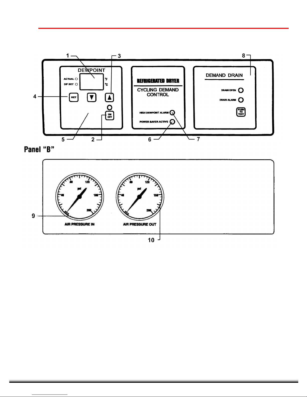
1) DEW POINT CONTROLLER AND DISPLAY.
Directly controls dew point and provides constant
digital display of dew point. Factory set at 36ºF.
During ACTUAL display mode, displays the dew
point temperature from 20º to 99º F or -6º to 37º C.
During DP SET mode, the unit displays dew point
set points from 34º to 50ºF in 1º steps, or 1º to
10ºC in 1/2 steps. (Note that the ones digit decimal
point is used to indicate 1/2º when displaying set
point in Celsius scale.) ºC LED- indicates that the
temperature is displayed in Celsius. ºF LED –
indicates that the temperature is displayed in
Fahrenheit. ACTUAL LED – indicates the display
is in ACTUAL mode. Display shows actual
temperature being measured by system. DP SET
LED - Indicates that the display is in programming
mode during which the set point can be changed
and stored. The dew point display also displays
the unit error codes when they occur. (see
Diagnostic codes)
2) ON/OFF BUTTON .LED - Indicates when the unit is
operating.
3) RAISE and LOWER BUTTONS. These are used to
adjust the set point values. The set point will
change once for each time pressed. If the button
is pressed and held, the set point will change one
step per second.
4) SET BUTTON. Toggles between Actual Display
mode and Set point Display mode. During the Set
point Display mode, the Raise and Lower keys are
used to select new set points which are stored in
nonvolatile memory when the mode is set back to
ACTUAL. If no keys are pressed within 15 seconds, the mode is automatically set to “ACTUAL”.
This switch is also used to select the temperature
scale that the unit will operate in. By pressing and
holding for 5 seconds the unit will toggle between
the Fahrenheit and Celsius scale.
5) HIDDEN BUTTON. Positioned in the bottom center
of the Dew Point window between the MODE keys.
When pressed, the display will show the external
suction temperature at the expansion bulb. It has
no further effect on operation. It may also be used
for other diagnostics and factory test purposes
6) POWER SAVER ACTIVE LED. Unit in mode of
minimal power consumption.
7) HIGH DEW POINT ALARM LED. Indicates that the
unit is in the High Dew Point condition. The high
dew point alarm light, with remote dry contacts, will
activate when the actual dew point is 15º F higher
than the dew point set point. Any diagnostic code
will activate the high dew point alarm immediately.
17
8) DRAIN CONTROL. Will operate by either a ‘LEVEL
FLOAT’ or ‘TIMED’ interval. If the dryer is equipped
with a Level Float (electrical connections to terminal
J9), the drain will respond to the float signal on
demand to operate the drain. The duration that the
drain valve is open, will be the amount of time it
takes for the fluid level to drop and reset the float
signal, plus, a pre-set time of a few seconds
thereafter. The drain valve will also operate automatically once every 30 minutes (independent to the
float signal). The 30 minute timed interval setting
can be adjusted down to 1 minute or raised up to 60
minutes if desired. To adjust the drain ‘Timed
Interval’ setting, press the SET button twice (note
that the Actual and DP Set LED’s will both extinguish). The value indicated in the display will be the
Timed Interval setting. Use the UP or DOWN arrow
to the desired timing set point. Pressing the SET
button again will return the display to reading the
dew point and the ‘Actual’ LED will once again
illuminate.
9-10) AIR INLET and AIR OUTLET PSI GAUGES.
Indicates that unit is pressurized. Unit must be
depressurized and bypassed before any service
work is done on air system. Excessive pressure
drop (more than 5 PSIG) across dryer indicates
water may be freezing in the evaporator.
EXTERNAL SENSORS, CONTROLS and RELAYS
DRAIN RELAY (K1) – This onboard relay opens the drain
valve according to drain controls.
SUCTION RELAY (K2) – This onboard relay turns on
according to the mode and dew point conditions and
opens the suction or liquid line valve when active.
UNLOADER RELAY (K3) – not applicable.
COMPRESSOR RELAY (K4) – This onboard relay
controls the compressor according to the mode and dew
point conditions.
HIGH DEW POINT RELAY (K5) – This onboard relay and
LED alarm turns on when the dew point is 15º F above
the set point. This is also active during any error
conditions.
DEW POINT SENSOR (Probe 1) – Resistive NTC sensor
for measuring dew point temperature.
SUCTION TEMPERATURE SENSOR (Probe 2) – Resistive
NTC sensor for measuring external suction temperature
at the expansion bulb (E3 Probe).
Page 18
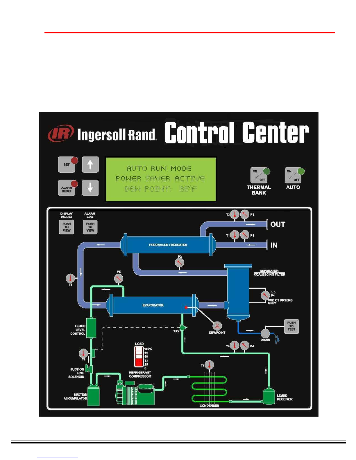
Optional Electronic Panel
MANUAL
18
Page 19

PREFACE:
This document is intended to make familiar, the Control Center functionality. The ‘manual’, can serve as
a handy guide to quickly move through the operations of the dryer it is controlling. It is not intended to
replace the more comprehensive, specific ‘dryer manual’ that will show all other aspects of operation
and safety. It is IMPORTANT that both manuals be referenced for complete dryer understanding.
MENU TREE
a. STARTUP NULL SCREEN------------------------------------------------------------------------------------ [ 20 ]
• VCD - VARIABLE SPEED DRYER
-------------- PRE-STARTUP
--------------------- STARTUP
--------- CHANGE MODES
b. MAIN SCREEN --------------------------------------------------------------------------------------------------- [ 20 ]
• DISPLAY ORIENTATION
• TYPICAL SCREEN DISPLAYS
c. EVENTS ------------------------------------------------------------------------------------------------------------- [ 21 ]
• EMERGENCY STOP
• STANDBY
• DEWPOINT OPTION (not installed)
• ACTIVE ALARMS
• DEWPOINT ALARM
• NO FLOW
19
d. REVIEW ALARM LOG (‘J’ Series Menus) ---------------------------------------------------------------- [ 22 ]
e. DISPLAY SENSOR VALUES (‘K’ Series Menus) ------------------------------------------------------ [ 24 ]
• FLOW MONITOR (4-20mA / 1 to 5 volt input)
MAIN MENU
1. DEWPOINT SETTINGS (‘D’ Series Menus) ------------------------------------------------------------------------------------ [ 25 ]
• DEWPOINT SET
2. SETUP MENU (‘E’ Series Menus) -------------------------------------------------------------------------------------------------- [ 25 ]
• COMPANY INFORMATION ----------------------------------------------------------------------------------------------- [ 25 ]
PHONE & www MESSAGE
• PRODUCT INFORMATION ------------------------------------------------------------------------------------------------ [ 25 ]
TYPE OF DRYER & SN#
FACTORY DEFAULTS
GOTO ‘NULL’ STATE
CALIBRATION MENU (‘H’ Series Menus)
INLET PRESSURES
REHEATER PRESSURE
OUTLET PRESSURE
DISCHARGE PRESSURE
SUCTION PRESSURE
ELEMENT DP SETTINGS
FLOW RANGE SETTINGS
• DRAINS SETUP MENU (‘I’ Series Menus) ------------------------------------------------------ [ 27 ]
#1 DEMAND or TIMED OPERATIONS
#1 INTERVAL (Timed)
#1 DURATION
#1 AUTOTEST
Page 20

#2 DEMAND or TIMED OPERATIONS
#2 INTERVAL (Timed)
#2 DURATION
#2 AUTOTEST
• COMMUNICATIONS MENU (‘F’ & ‘G’ Series Menus) ----------------------------------------- [ 28 ]
ADJUST CLOCK
STAR WATCH -Host to Control: YES
MODEM SETUP
MODEM ENABLE
MODEM TEST
MODEM RESET (Reprogram)
VIEW MODEM SETTINGS
3. SENSOR SETTINGS (‘C’ Series Menus)----------------------------------------------------------------- [ 28 ]
• P1: LOW INLET PRESSURE
• P1: HIGH INLET PRESSURE
• P2: REHEATER PRESSURE
• P3: OUTLET PRESSURE
• P4: DISCHARGE PRESSURE
• P5: SUCTION PRESSURE
• P6: SEPARATOR DP
• FLOW
20
4. TEMPERATURE SETTINGS (‘B’ Series Menus) ---------------------------------------------------------[ 29 ]
• T1: DRYER INLET SETPOINT
• T2: PRECOOLER SETPOINT
• T3: DRYER OUTLET SETPOINT
• T4: REFRIGERANT SETPOINT
• T5: SUCTION SETPOINT
• T6: AMBIENT/H2-0 SETPOINT
5. VIEW ALARMS (‘A’ Series Menus) ---------------------------------------------------------------------------[ 29 ]
• HIGH DEWPOINT
• LOW FLOW
• (E1/E2) DEWPOINT PROBE FAULT (OPEN OR SHORT)
• MOTOR OVERLOAD
• (E3) SUPERHEAT OUT OF RANGE
• (E4) LOW DEWPOINT
• (E5) DRYER OVERLOAD
• (E6) LOW FREON OR OIL PRESSURE
• (E7) HIGH FREON PRESSURE
• (WI) LOW AIR-IN PSI
• (W2) HIGH AIR-IN PSI
• (W3) COALESCER PSID
• (W4) HIGH INLET AIR TEMP
• (W5) HIGH AMBIENT / H2-0 TEMP
• (W6) DRAIN FAULT
• MODEM FAULT
Page 21
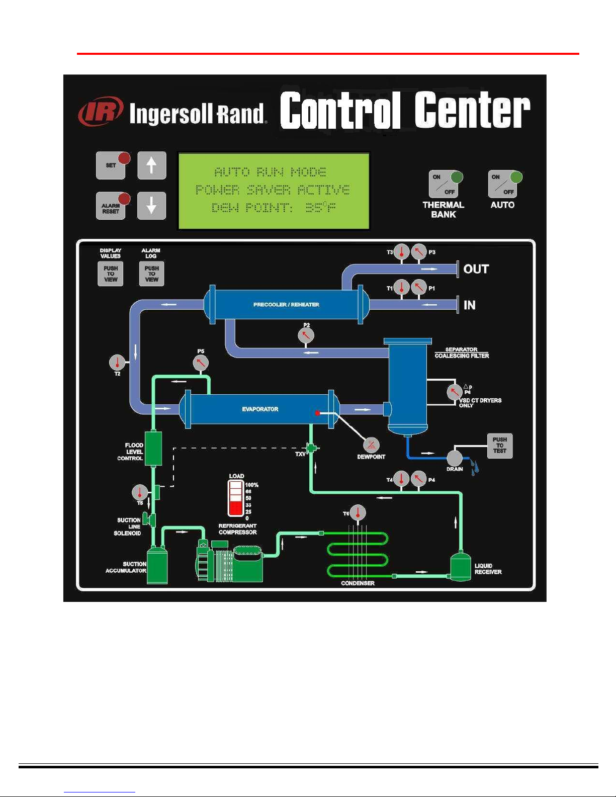
KEY FUNCTIONS
21
1. UP ARROW Scroll Menu Up or Increment Value
2. DOWN ARROW Scroll Menu Down or Decrement Value
3. SET Enter Menu Selection, Enter Program Mode or Save to Memory
4. RESET ALARM Back-up Menu Level or Clear ‘Resetable’ Alarm
5. LOAD/UN-LOAD Load/Un-Load Mode Selector
6. THERMAL BANK Thermal Bank Mode Selector
7. AUTO RUN Auto Mode Selector - Automatically Sequences to Demand (#5 or #6)
8. DRAIN TEST Operates Both Drain System for Programmed Duration
9. DISPLAY VALUES Enters Sensor Menus - Indicates Current Values (Series ‘K’ Screens)
10.REVIEW ALARM LOG Enters Historical Log of Alarm Event (Series ‘J’ Screens)
Page 22
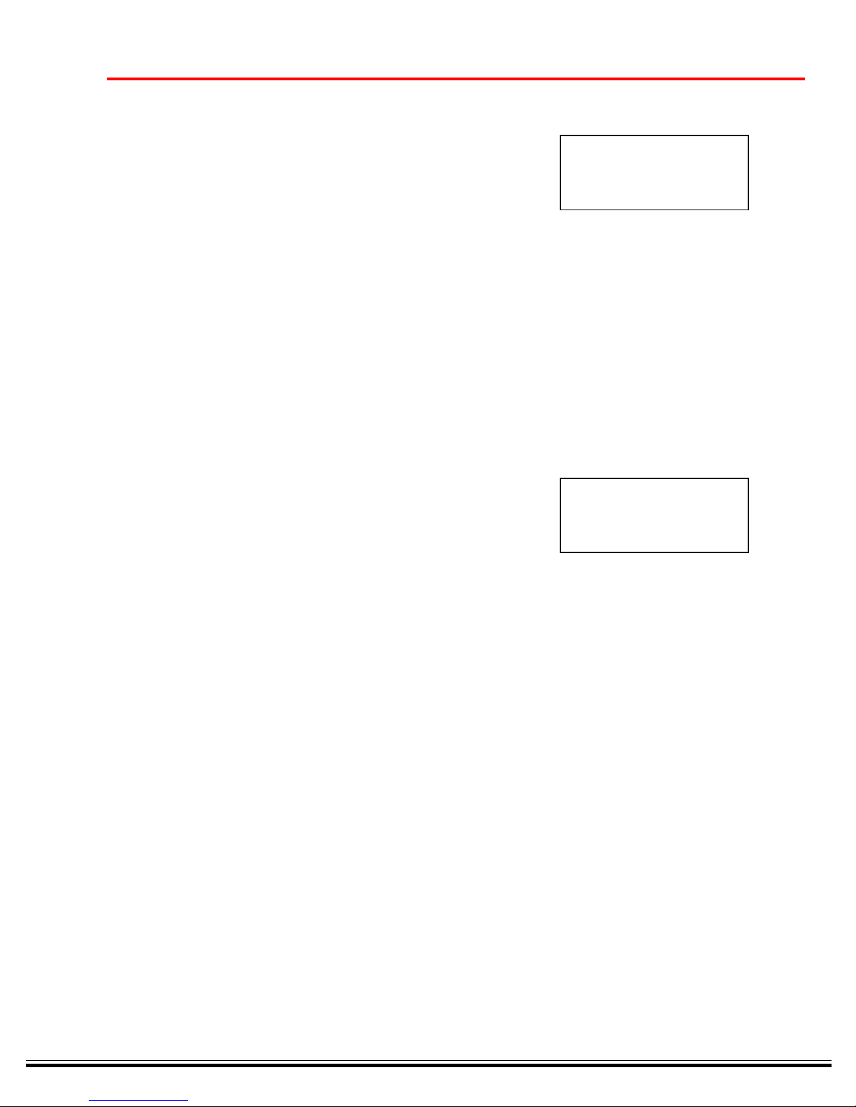
a. STARTUP NULL SCREEN ------------------------------------------------------------------------------------------------------------------------------
Upon initialization, the display shows the ‘type’ of dryer the Control Center is configured to control.
• VCD - VARIABLE SPEED DRYER
INGERSOLL-RAND
VCD
REFRIGE DRYER (R404A)
S/N 00000 V 1.00
This is a fixed configuration. Once assigned to a dryer the Control Center will never be changed to any of the other
configurations. Note that the Control Center Serial Number and Firmware Version are also displayed on this null,
initialization screen.
PRE-STARTUP
Prior to starting up the dryer,’ the DISPLAY VALUES button may be selected to view groupings of sensors
(use the up/down arrows to scroll through the list) Depress the Display Values button a second time, or the
Alarm RESET button to return to the Main Screen. Also, all of the other screens and menus can be viewed
by using the up/down arrows. Simply position any particular menu choice into view and advance a menu
level by depressing the SET button. A return to the Main Screen can be achieved at any time by depressing
the Alarm RESET button. These screens may be viewed at any time, and at any state of operation.
22
The Main Screen will indicate SYSTEM INACTIVE prior to start-up (run mode), when returning to the Main
Screen from viewing any of the above Pre-Startup procedures.
SYSTEM INACTIVE
DEWPOINT 65°F
STARTUP
TO START the dryer select any of the three main operating modes by depressing their button.
• AUTO Mode (normal operations) dryer will automatically sequence.
CHANGING MODES
The dryer can change modes of operation by simply depressing the any desired mode button. To return the
dryer to an INACTIVE (SYSTEM OFF) state, depress the ‘current mode’ button as is indicated by the Mode
Pilot indicator (LED).
b. MAIN SCREEN ------------------------------------------------------------------------------------------------------------------------------------------
DISPLAY ORIENTATION There are several informational indications displayed on the Main Screen. They are
displayed on the four lines of the LCD.
1. The first line is the ‘message’ line. If all is normal, this line will indicate ALL SYSTEMS OK, else it will
indicate an alarm; for example, HIGH DEWPOINT. If more than one alarm is active, this message line
will ‘scroll’ between any and all messages.
2. The second line is the ‘mode’ line~. This line will indicate the dryers operations:
• SYSTEM INACTIVE,
• EMERGENCY STOP,
• AUTO RUN MODE,
• LOAD/UNLOAD MODE,
• THERMAL BANK MODE,
• SYSTEM OFF, and
• ALARM SHUT DOWN
3. The third line is the ‘process’ line. INITIALIZING, POWERSAVE ACTIVE or may be blank for all other
normal operations.
4. The forth line is dedicated to the current DEWPOINT value.
Page 23
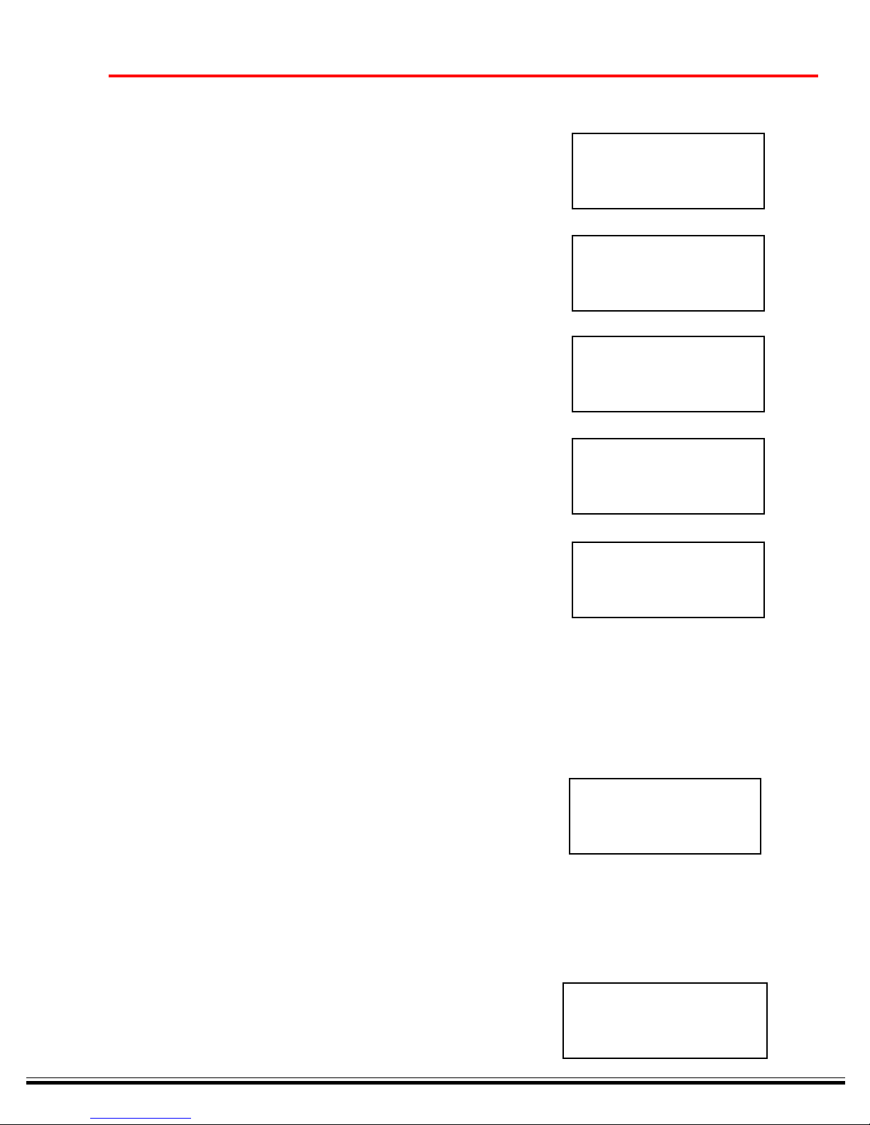
TYPICAL SCREEN DISPLAYS ------------------------------------------------------------------------------------------------------------
Below are a sampling of typical display screens; showing some of the possible system operations.
ALL SYSTEMS OK
AUTO RUN MODE
POWERSAVE ACTIVE
DEWPOINT 34°F
MOTOR OVERLOAD
ALARM SHUT DOWN
DEWPOINT 39°F
ALL SYSTEMS OK
LOAD/UNLOAD MODE
DEWPOINT 35°F
ALL SYSTEMS OK
SYSTEM OFF
23
DEWPOINT 65°F
STARWATCH ACTIVE
AUTO RUN MODE
DEWPOINT 33°F
c. EVENT -----------------------------------------------------------------------------------------------------------------------------------------------
EMERGENCY STOP -------------------------------------------------------------------------------------------
At any time the dryer’s E-STOP pushbutton is depressed, the dryer will immediately ‘stop’
operations (all output will be de-energized except for COMMON ALARM dry output relay
and the MODEM relay). To restart the dryer, the flashing mode (AUTO RUN, LOAD/
UNLOAD or THERMAL BANK) selector must be re-selected. Note - the E-STOP
pushbutton must be rotated and pulled ‘out’ to its normal position before the re-start can be
invoked.
ACTIVE ALARMS
EMERGENCY STOP!
DEWPOINT 35ºF
ALARM SHUT DOWN
When a ‘shut-down’ alarm occurs, the dryer will ‘stop’ operating and will require a Manual
Reset (see VIEW ALARMS section). Once the alarm has been reset and if the alarm
condition has been cleared, the system may be re-started. The current mode LED will be
flashing. When the mode selector button is depressed, the system will restart and the LED
will stop flashing and remain illuminated.
LOW REFRIDGERANT/OIL PSI
ALARM SHUT DOWN
DEWPOINT 35 F
Page 24
24
_______________________________________________________________________________________________________
IMPORTANT:
___________________________________________________________________________________
All screens from section (d.) forward to the end of this manual are indicated with an alphanumeric
indication in the upper left corner of the display as a screen ID. The CONTROL CENTER will display these
ID’s as any given screen is selected within the menu tree. Please make note of any particular screen ID
when communicating with Ingersoll-Rand Service Providers, which may be in question.
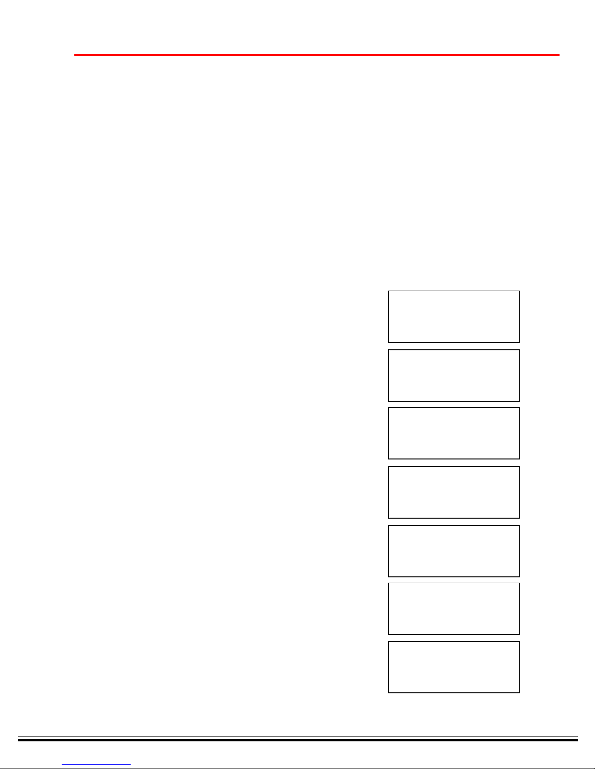
d. REVIEW ALARM LOG ------------------------------------------------------------------------------------------------------------------------
When the Review Alarm Log pushbutton is depressed, the ‘1’ series screens will be displayed. Each ‘1’ screen
shows the status of a possible alarm. The UP/DOWN arrow will allow scrolling through 16 different alarm conditions.
The number appearing next the ‘DAYS SINCE LAST’, indicated the last time that the alarms condition has occurred.
A zero (0) indicates the current date. For example, 365 would indicate exactly one year since the occurrence of any
particular alarm. If ‘—’ is indicated, that means the selected alarm has never happened.
When an alarm is tripped, the ‘COMMON ALARM RELAY’ (K16) will energize if the ‘ALARM OUT’ is ENABLED.
There is a form ‘c’ dry contact available for the user on K16 (see schematic). To ‘DISABLE’ the ALARM OUT from
energizing the Common Alarm relay, use the SET and UP/DOWN arrow buttons. All alarms are factory default to
‘ENABLED’. The user can program any one, any combination, or all alarms to activate the Common Alarm relay.
J1 ALARM LOG
HIGH DEWPOINT
DAYS SINCE LAST: 1
ALARM OUT: ENABLED
J2 ALARM LOG
LOW FLOW
DAYS SINCE LAST: 25
ALARM OUT: ENABLED
J3 ALARM LOG
DP PROBE FAULT
DAYS SINCE LAST: 365
ALARM OUT: ENABLED
J4 ALARM LOG
MOTOR FAULT
DAYS SINCE LAST: - - -
ALARM OUT: ENABLED
J5 ALARM LOG
E3: HI SUPERHEAT ºF
DAYS SINCE LAST: - - -
ALARM OUT: ENABLED
J6 ALARM LOG
E4: LOW DEWPNT/PUMP DOWN
DAYS SINCE LAST: 0
ALARM OUT: ENABLED
J7 ALARM LOG
E5: DRYER OVERLOAD
DAYS SINCE LAST: - - -
ALARM OUT: ENABLED
Page 25
LOW REFRIGERANT/OIL PRESSURE
HIGH REFRIGERANT PRESSURE
25
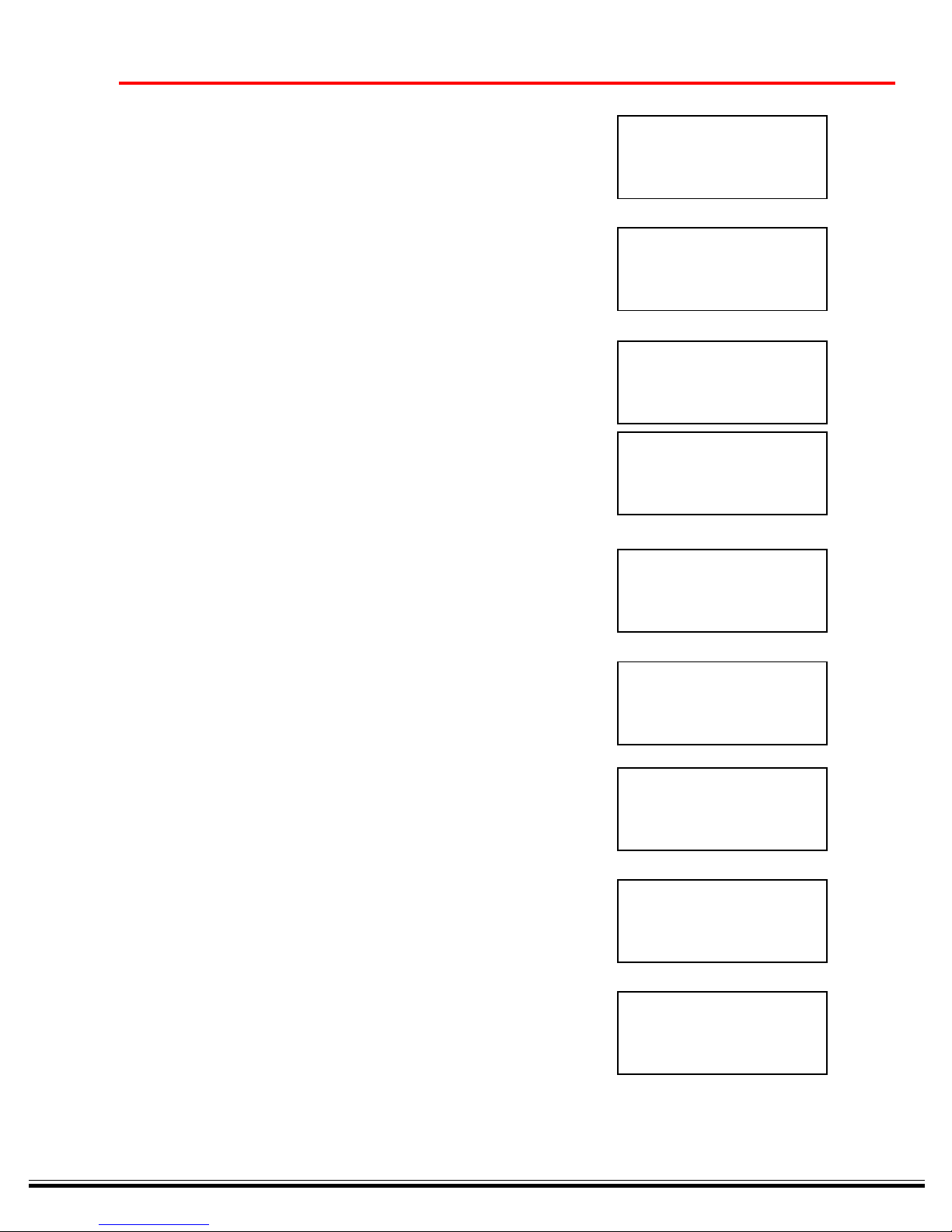
J8 ALARM LOG
E6: LOW PRESSURE
DAYS SINCE LAST: 0
ALARM OUT: ENABLED
J9 ALARM LOG
E7: HIGH PRESSURE
DAYS SINCE LAST: - - ALARM OUT: ENABLED
JI0 ALARM LOG
W1: LOW AIR-IN PSI
DAYS SINCE LAST: 54
ALARM OUT: ENABLED
J11 ALARM LOG
W2: HIGH AIR-IN PSI
DAYS SINCE LAST: - - ALARM OUT: ENABLED
COALESCER ELEMENT DIFFERENTIAL PRESSURE
J12 ALARM LOG
W3: CHANGE FILTER
DAYS SINCE LAST: —
ALARM OUT: ENABLED
J13 ALARM LOG
W4: HIGH AIR-IN ºF
DAYS SINCE LAST: —
ALARM OUT: ENABLED
J14 ALARM LOG
W5: HIGH AMBIENT/H2-0
DAYS SINCE LAST: —
ALARM OUT: ENABLED
J15 ALARM LOG
E9: DRAIN FAULT
DAYS SINCE LAST: —
ALARM OUT: ENABLED
J16 ALARM LOG
MODEM FAULT
DAYS SINCE LAST: 1
ALARM OUT: ENABLED
Page 26

e. DISPLAY SENSOR VALUES ------------------------------------------------------------------------------------------------------------------------------
The DISPLAY VALUE pushbutton is a quick way to view groupings of sensor values. The UP/DOWN arrows will
scroll through the 7 possible groups of the ‘K’ series screens.
Kl: Superheat ºF 12
T4: Refrig ºF 130
P4: Discharge psi 100
P5: Suction psi 96
K2: Superheat ºF 12
T5: Suction ºF 100
P5: Suction PSI 100
K3: Dewpoint ºF 33
Tl: Inlet ºF 100
PI: Inlet psi 100
T6: Ambient/H2-0 of 54
K4: Inlet psi 100
P1: Inlet psi 100
P3: Outlet psi 100
P6: Filter Element OK
26
K8 = RMV Screen (Relative Measurement Values)
FLOW METER-
All Control Center’s come standard with flow sensor input capabilities. Simply ’hook- up’ a 4-20mA
loop, or, a 1 to 5 volt signal to the appropriate flow input (see schematic/wiring diagram) and activate
the FLOW ENABLE in the SETUP screens. The loop may be powered by the Control Center or
powered externally. The FLOW measurement is displayed in the ‘K6’ screen only if enabled. Refer
to schematic for configuring panel to ‘current/voltage’ and wiring. Call Ingersoll-Rand Service Support
for details or questions.
K5
Tl: Inlet ºF 100
T3: Outlet ºF 90
K6
T6: Ambient/H2O ºF67
P4: Discharge psi 250
K7 Tl: Inlet ºF 100
T3: Outlet ºF 90
PI: Inlet psi 100
P3: Outlet psi 98
K8 Power 10.4 Kw
Current 12.4 A
Speed 1300 RPM
Frequency 45 Hz
Page 27
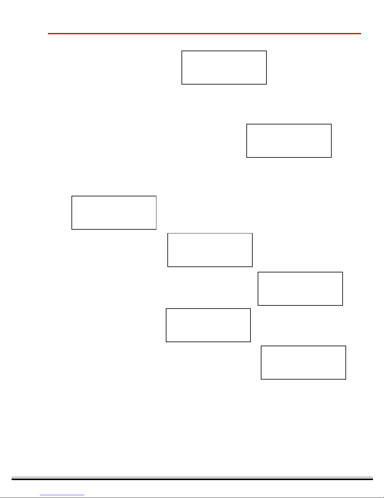
1. DEW POINT MENU ---------------------------------------------------------------------------------------------------------------------------------------
DEWPOINT
MENU
Press SET to select
DEWPOINT - The dryer will attempt to deliver a dew point relative to the
DEWPOINT SET POINT value. The range can for this setting can be selected between
34ºF to 50°F.
When the dew point indicated the set point value or less, the panel LCD display will give a message: POWERSAVE ACTIVE
D1 DEWPOINT
Value: 36°F
Set point. 34ºF
2. SETUP MENU ----------------------------------------------------------------------------------------------------------------------------------
Screen series ‘E’, ‘F’, ‘G’, ‘R’ and ‘I’ are within the set-up selections.
SYSTEM - E & H SERIES SCREENS
SETUP
MENU
27
Press SET to select
E1 COMPANY
INFORMATION
Press SET to select
E1 Ingersoll-Rand
(1-800-526-3615)
Copyright( c )2001
E2 PRODUCT
INFORMATION
Press SET to select
E2 VCD - Variable Speed
AIR DRYER
Serial # 00000
Firmware Rev. 1.00
______________________________________________________________________________________________________
FACTORY DEFAULTS - To set all parameters to there factory setting, depress the SET pushbutton
when in the ‘E7’ screen. IMPORTANT: Make sure that all calibrations are set to currently installed
ranges of the sensor transducers. For example, if in servicing the dryer and there was a replacement of a pressure transducer with a range of 0 to 250 (instead of the factory installed transducer
with a range of 0 to 200), then the Factory Defaults will need to be re-adjusted for that particular
channel (see CALIBRATION MENU).
Page 28
E4 DRAIN SETUP
MENU
28
Press SET to select
I1 DRAIN 1
Type: DEMAND
Interval: 10:00 m:s
Duration: 2 sec
I2 DRAIN 1
Type: DEMAND
Interval: 10:00 m:s
Duration: 2 sec
I3 DRAIN 1
Type: DEMAND
Interval: 10:00 m:s
Duration: 2 sec
I4 DRAIN 1
On Delay: 0:05 m:s
AutoTest: 12:00 h:m
I5 DRAIN 1
On Delay: 0:05 m:s
AutoTest: 12:00 h:m
I6 DRAIN 2
Type: DEMAND
Interval: 10:00 m:s
Duration: 2 sec
I7 DRAIN 2
Type: DEMAND
Interval: 10:00 m:s
Duration: 2 sec
I8 DRAIN 2
Type: DEMAND
Interval: 10:00 m:s
Duration: 2 sec
I9 DRAIN 2
Type: DEMAND
Interval: 10:00 m:s
Duration: 2 sec
I10 DRAIN 2
Type: DEMAND
Interval: 10:00 m:s
Duration: 2 sec
Page 29
29
CAUTION!
The Factory Default will change all process values and set points back to their original factory settings.
PROCEED WITH CAUTION...
E7 RESET SETTINGS
TO FACTORY DEFAULTS
PROCEED WITH CAUTION
Press SET to select
______________________________________________________________________________________________________
NULL STATE - When the Null State is selected, all operations will cease. The dryer display will go
to one of the three possible initialization screens as shown in section 1.0 (see STARTUP NULL
SCREEN).
CAUTION!
The ‘Reset Unit to Null State’ will immediately stop all operations and display the initializations screen.
PROCEED WITH CAUTION........
E6 RESET UNIT
TO NULL STATE
PROCEED WITH CAUTION
Press SET to select
There is a Diagnostics Screen that shows general information that will be useful if service is ever necessary
to the Control Center panel (NOTE: a ‘.1’ indicates NEVER happened.)
E8 DAY/OPER: 365
Total Resets: 12
Stack Mem: -1
Last Reset: X00X00X00
CALIBRATlON MENU . Each of the transducers in the system have their ranges set in the ‘H’ series
screens. It is important that the value indicated in the screens match the maximum range of the
transducer span. If while servicing the dryer, and a different ranged transducer is replacing a factory
installed transducer, make certain a corrected value for maximum range is entered in the appropriate screen.
E5 CALIBRATION
MENU
Press SET to select
HI Inlet Pressure
Value: 100 psi
Offset: 0 psi
Scale: 200 psi
Page 30
H2 Inlet Pres
Value: 100 psi
Offset: 0 psi
Scale: 200 psi
H3 Outlet Pres
Value: 100 psi
Offset: 0 psi
Scale: 200 psi
H4 Outlet Pres
Value: 100 psi
Offset: 0 psi
Scale: 200 psi
H5 Discharge Pres
Value: 300 psi
Offset: 0 psi
Scale: 600 psi
H6 Discharge Pres
Value: 300 psi
Offset: 0 psi
Scale: 600 psi
30
H7 Suction Pres
Value: 60 psi
Offset: 0 psi
Scale: 600 psi
H8 Suction Pres
Value: 60 psi
Offset: 0 psi
Scale: 600 psi
H9 Flow
Value: 0 scfm
Offset: 0 scfm
Scale: 1000 scfm
H10 Flow
Value: 0 scfm
Offset: 0 scfm
Scale: 1000 scfm
Page 31
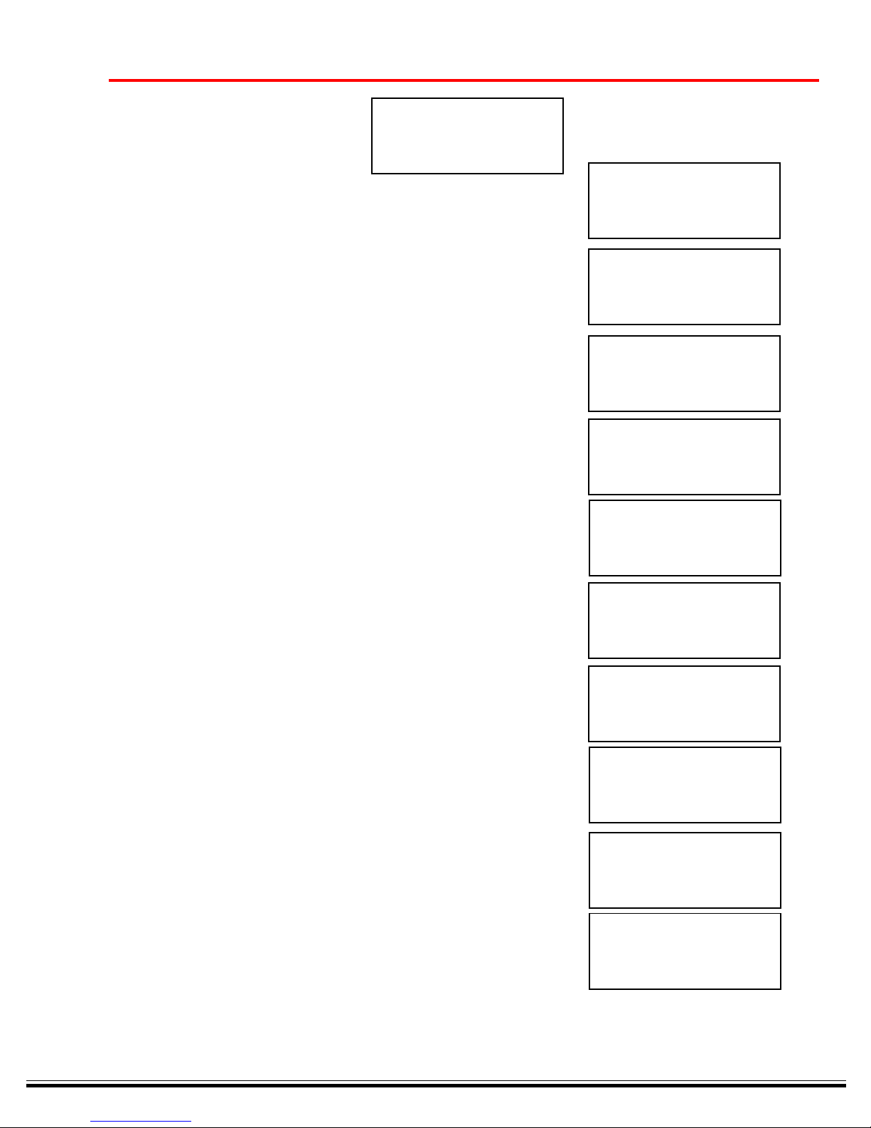
SYSTEM DRAINS - E & I SERIES - Each of the two (2) drain controls can be programmed to be
either a ‘TIMED’ or ‘DEMAND’ drains.
• If Timed is selected, the drain will activate to the ‘Interval’ time setting for the period of time
indicated in the ‘Duration’ time setting.
• If Demand is selected, the drain will operate for the period of time indicated in the ‘Duration’
time setting, when a drain input signal is sensed from the demand drain float. A DRAIN FAULT
Alarm can occur if float does not respond as expected. When an fault is detected, the drain
solenoid will be ‘pulsed’ for ten minutes in an attempt to clear the faulted drain.
• The ‘Auto Test’ feature will operate the drain for the period of time indicated in the Duration
setting at the specified Interval. This feature is intended to prevent sediment buildup by activating the drain periodically and ‘blowing out’ any possible debris.
E4 DRAIN SETUP
MENU
Press SET to select
I1 DRAIN 1
Type: DEMAND
Interval: 10:00 m:s
Duration: 2 sec
31
I2 DRAIN 1
Type: DEMAND
Interval: 10:00 m:s
Duration: 2 sec
I3 DRAIN 1
Type: DEMAND
Interval: 10:00 m:s
Duration: 2 sec
I4 DRAIN 1
On Delay: 0:05 m:s
AutoTest: 12:00 h:m
I5 DRAIN 1
On Delay: 0:05 m:s
AutoTest: 12:00 h:m
I6 DRAIN 2
Type: DEMAND
Interval: 10:00 m:s
Duration: 2 sec
I7 DRAIN 2
Type: DEMAND
Interval: 10:00 m:s
Duration: 2 sec
I8 DRAIN 2
Type: DEMAND
Interval: 10:00 m:s
Duration: 2 sec
Page 32
SYSTEM COMMUNICATIONS - F & G SERIES
32
I9 DRAIN 2
On Delay: 0:05 m:s
AutoTest: 12:00 h:m
I10 DRAIN 2
On Delay: 0:05 m:s
AutoTest: 12:00 h:m
E3 COMMUNICATIONS
MENU
Press SET to select
Fl ADJUST CLOCK
Time: 12:15
New Time: 12:20
F2 STARWATCH
Host To Control: YES
F3 MODEM
MODEM SETUP
Press SET to select
G1 MODEM ENABLE
Enabled: YES
G2 MODEM TEST
Press SET to
test modem
G3 MODEM RESET
Press SET to
reset modem
3. SENSOR SETTINGS ----------------------------------------------------------------------------------------------------------------------------------------
SENSOR
SETTINGS
Press SET to select
CI PI: LOW INLET
Value: 100 psi
Alarm Set: 40 psi
Page 33
FLOW INPUT ENABLE: YES
If “Yes” : gives flow data C6 FLOW SENSOR
If “No” : gives % of load VCD drive Enabled: NO
FLOW ALARM SET POINT
33
C2 PI: HIGH INLET
Value: 100 psi
Alarm Set: 101 psi
C3 P4: DISCHARGE
Value: 290 psi
Alarm Set: 350 psi
C4 P5: SUCTION
Value: 100 psi
Alarm Set: 20 psi
Value: 0 scfm
Alarm Set: 0 scfm
C7 FLOW SENSOR
Enabled: NO
Value: 0 scfm
Alarm Set: 0 scfm
4. TEMPERATURE SETTINGS ------------------------------------------------------------------------------------------------------------------------------TEMPERATURE
SETTINGS
Press SET to select
B1 T1: DRYER INLET
Value: 72°F
Alarm Set: 101ºF
B2 T3: DRYER OUTLET
Value: 86°F
Alarm Set: 101°F
B3 T4: REFRlG.
Value: 87°F
Alarm Set: 188°F
B4 T6: AMBIENT/H2-0
Value: 47°F
Alarm Set: 75°F
Page 34
5 . VIEW ALARMS -----------------------------------------------------------------------------------------------------------------------------------------------
VIEW ACTIVE
ALARMS
Press SET to select
ACTIVE ALARMS
Press UP/DOWN to
view active alarms
Press RESET to Exit
Al ACTIVE ALARMS
HIGH DEWPOINT
(Self Resetting)
Press RESET to Exit
A2 ACTIVE ALARMS
LOW FLOW
(Self Resetting)
Press RESET to Exit
A3a SYSTEM SHUTDOWN - Requires a manual reset.
34
A3b SYSTEM SHUTDOWN - Requires a manual reset.
A4 SYSTEM SHUTDOWN - Requires a manual reset.
A5a SYSTEM SHUTDOWN - Requires a manual reset.
A3 ACTIVE ALARMS
E1: DP PROBE OPEN
Press RESET to Clear
A3 ACTIVE ALARMS
E2: DP PROBE SHORT
Press RESET to Clear
A4 ACTIVE ALARMS
MOTOR FAULT
Press RESET to Clear
A5 ACTIVE ALARMS
E3: SUPERHEAT. HIGH
Press RESET to Clear
A13 ACTIVE ALARMS
W4: HIGH AIR-IN of
(Self Resetting)
Press RESET to EXIT
A14 ACTIVE ALARMS
W5: HIGH AMBIENT/ H2-O
(Self Resetting)
Press RESET to EXIT
Page 35
A5b SYSTEM SHUTDOWN ..Requires a manual reset.
A6 SYSTEM SHUTDOWN - Requires a manual reset.
A7 SYSTEM SHUTDOWN - Requires a manual reset.
A8 SYSTEM SHUTDOWN - Requires a manual reset.
35
A5 ACTIVE ALARMS
E3: SUPERHEAT-LOW
Press RESET to Clear
A6 ACTIVE ALARMS
E4: LOW DEWPOINT
Press RESET to Clear
A7 ACTIVE ALARM S
E5: DRYER OVERLOAD
Press RESET to Clear
A8 ACTIVE ALARMS
E6: LOW REFRIDG/OIL PSI
A9 SYSTEM SHUTDOWN - Requires a manual reset.
A12 Requires a manual reset.
Press RESET to Clear
A9 ACTIVE ALARMS
E7: HIGH REFRIDGE/OIL PSI
Press RESET to Clear
A10 ACTIVE ALARMS
WI: LOW AIR-IN PSI
(Self Resetting)
Press RESET to EXIT
A11 ACTIVE ALARMS
W2: HIGH AIR-IN PSI
(Self Resetting)
Press RESET to EXIT
A12 ACTIVE ALARMS
W3: COALESCER PSID
Press RESET to Clear
A13 ACTIVE ALARMS
W4: HIGH AIR-IN of
(Self Resetting)
Press RESET to EXIT
A14 ACTIVE ALARMS
W5: HIGH AMBIENT/ H2-O
(Self Resetting)
Press RESET to EXIT
Page 36
A15a DRAIN #1 FAILURE
A15b DRAIN #2 FAILURE
A16 Requires a manual reset.
36
A15 ACTIVE ALARMS
DRAIN FAULT-l
(Self Resetting)
Press RESET to EXIT
A15 ACTIVE ALARMS
W6 DRAIN FAULT-2
(Self Resetting)
Press RESET to EXIT
A16 ACTIVE ALARMS
MODEM FAILURE
Press RESET to Clear
ACTIVE ALARMS
No Active Alarms
Press RESET to EXIT
Page 37
Page 38
Page 39
Page 40
Page 41
Page 42
Page 43
Page 44
Page 45
Page 46
Page 47
Page 48
Page 49
Page 50
Page 51
Page 52
Page 53
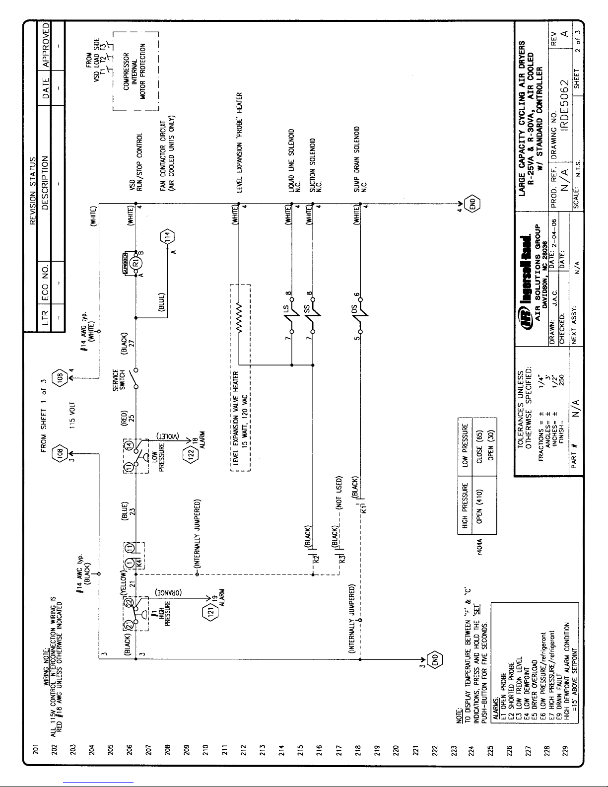
Page 54
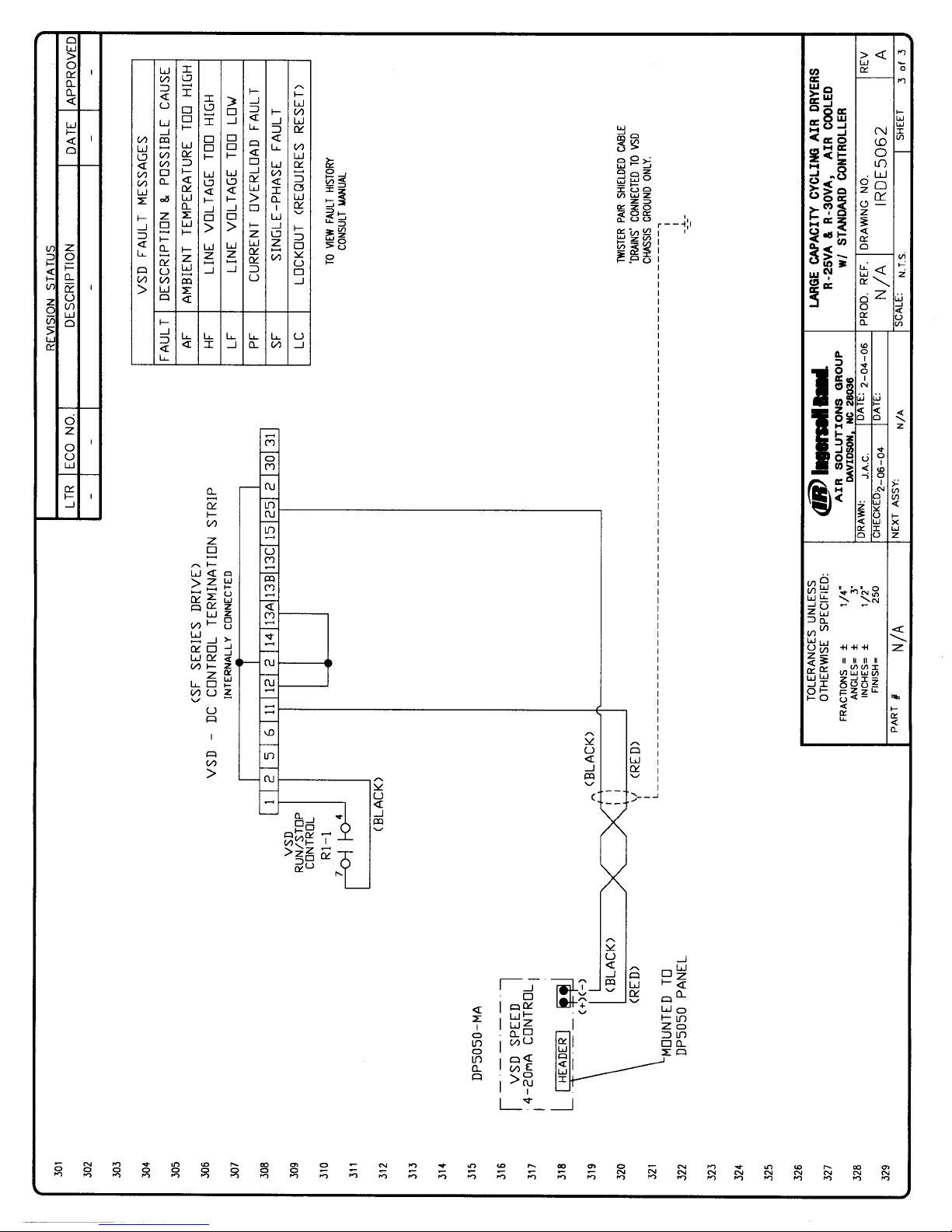
Page 55
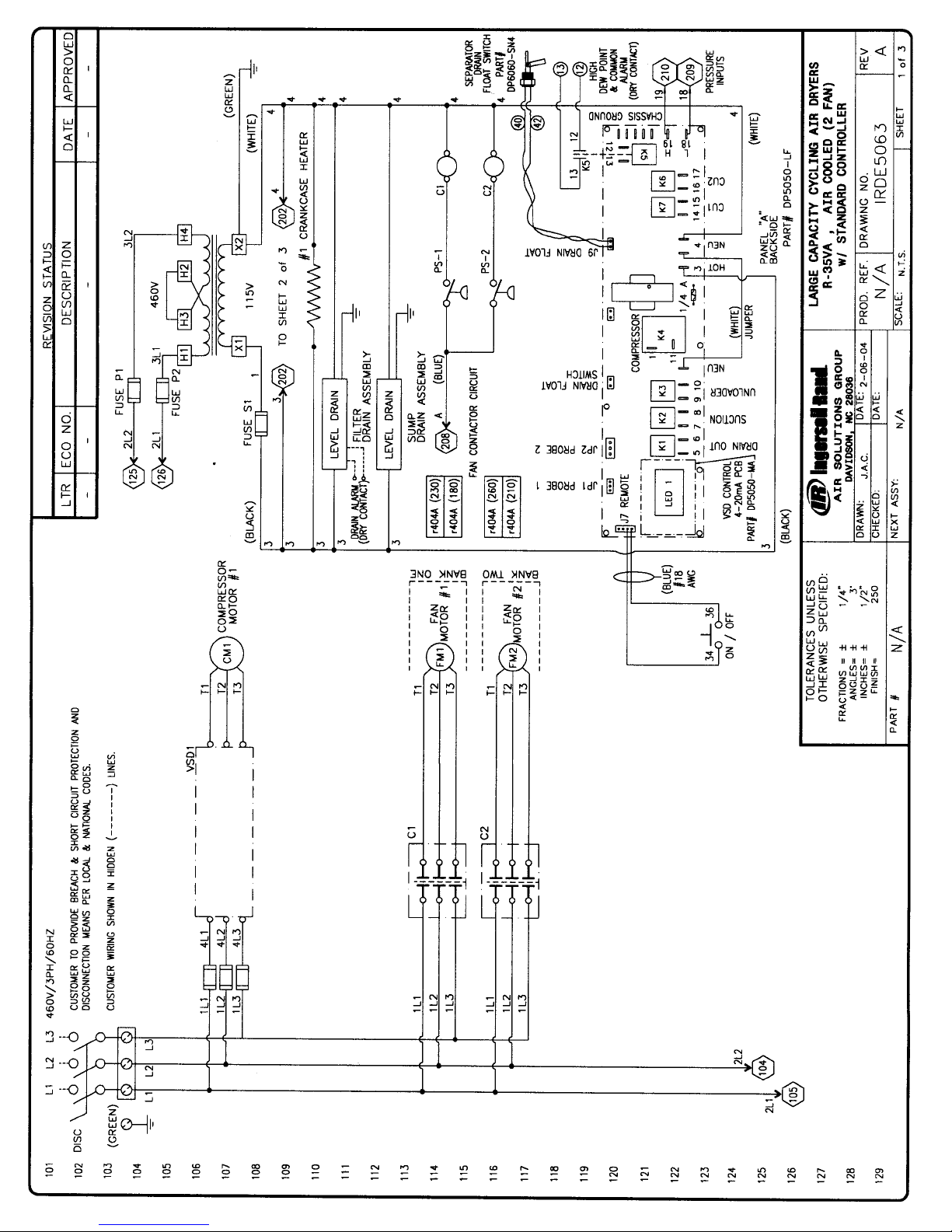
Page 56
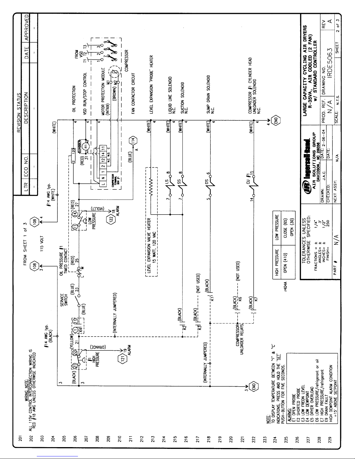
Page 57
Page 58
Page 59
Page 60
Page 61
Page 62
Page 63
Page 64
Page 65
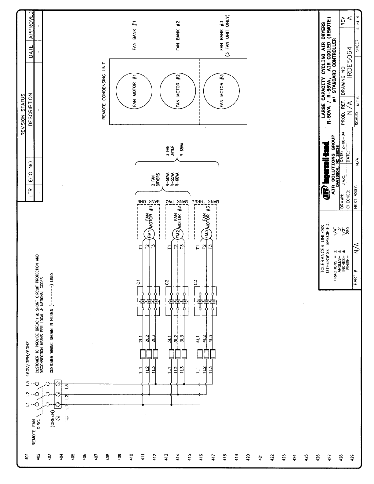
Page 66
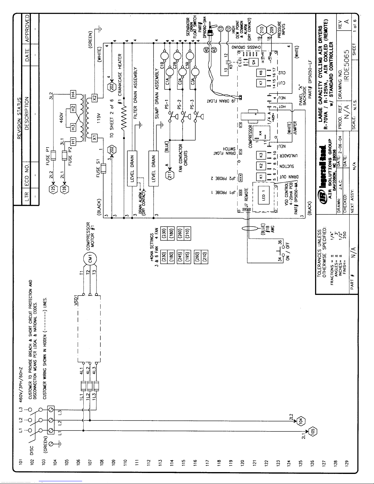
Page 67
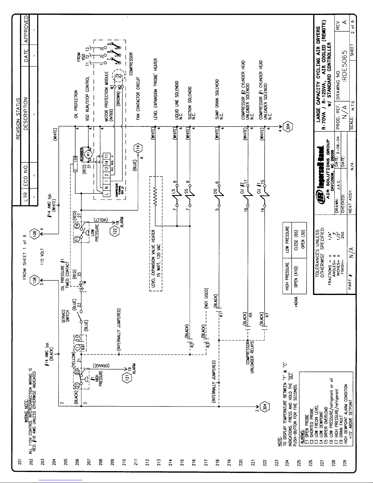
Page 68
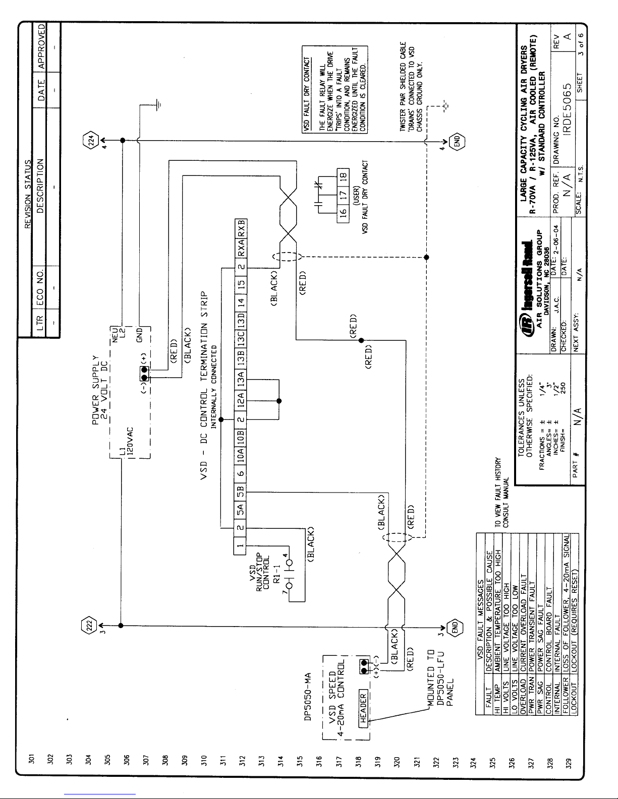
Page 69
Page 70
Page 71
Page 72
Page 73
Page 74
Page 75
Page 76
Ingersoll-Rand
Fold and Seal and your Service Warranty will be registered immediately. We are here to help.
For more information on Service or Installation call IR Customer Service at (1-800-526-3615).
®
IR?
Page 77
 Loading...