

Page 1
Fault Finding Guide for the R90-160 IU
More than Air Answers
Online answers: http://www.air.irco.com
PHONE: 1-800-820-0308
WSV June 07
Page 2

Safety First
Compressed air and electricity can be dangerous. Before undertaking any work on the compressor,
ensure that the electrical supply has been isolated and the compressor has been relieved of all
pressure. Use proper Lock Out Tag Out procedures to ensure you and your coworkers safety.
Keep all parts of the body and any hand-held tools or other conductive objects, away from exposed
live parts of the compressor electrical system. Maintain dry footing, stand on insulating surfaces and
do not contact any other portion of the compressor when making adjustments or repairs to exposed
live parts of the compressor electrical system. Close and lock all access doors when the compressor
is left unattended.
Do not use extinguishers intended for Class A or Class B fires on electrical fires. Use only
extinguishers suitable for class BC or class ABC fires. Attempt repairs only in clean, dry, well lighted
and ventilated areas. Connect the compressor only to electrical systems that are compatible with its
electrical characteristics and that are within it’s rated capacity.
WARNING
Imposing a normal or emergency stop on the compressor will only relieve pressure upstream
of the minimum pressure valve on top of the separator tank. If maintenance work is required
downstream of this valve, ensure that all pressure is relieved at the process vent point
external to the compressor This state is advised by selecting PACKAGE DISCHARGE
PRESSURE on the control panel.
2
Page 3

Table of Contents
Page
1. Overview of the Eiger control system ----------------------------------------------------------- 4
2. S3 Intellisys Controller Operating Instructions --------------------------------------------------5
3. S3 Intellisys Controller Software Navigation ---------------------------------------------------6
4. S3 Intellisys Controller Fault Indicators ---------------------------------------------------------7
5. Eiger Fault Finding ---------------------------------------------------------------------------------8-13
6. Star Delta Electrical Schematic -------------------------------------------------------------------14-15
7. Soft Start Electrical Schematic --------------------------------------------------------------------16-17
8. Line Start Electrical Schematic -------------------------------------------------------------------18-19
9. Process and Instrumentation Diagram ------------------------------------------------------------20-21
10. General Overview of the Compressor ------------------------------------------------------------22
11. Input/Output and Alarm Information for The Intellisys S3 Controller -----------------------23-25
• Analog Inputs/Outputs Information and Comments
• Digital Inputs/Outputs
12. S3 Intellisys Controller Serial Communications Information --------------------------------26
13. Eiger Maintenance Intervals ----------------------------------------------------------------------27-30
14. S3 Intellisys Input/Out Overview ---------------------------------------------------------------- 31
15. S3 Intellisys Fault Descriptions ------------------------------------------------------------------ 32-33
16. S3 Intellisys Operator Display Icons ------------------------------------------------------------ 34-41
17. Eiger Options ----------------------------------------------------------------------------------------42
• Low Ambient
• PORO
• Scheduled Start Stop
• Integral Sequencing
• Modulation Option and Adjustments ----------------------------------------------------43-44
16. Table 12 Standard S3 Menu Structure and Parameters ---------------------------------------45-48
17. Table 13 Modbus Register Listing ---------------------------------------------------------------49-50
18. Trip Codes List -------------------------------------------------------------------------------------51
19. Appendix 1 Thermistor Temperature Resistance Chart (2ATT) ---------------------------- 52-57
20. General Specifications for Eiger Packages ----------------------------------------------------- 58-79
3
Page 4
Overview of the Eiger Control System
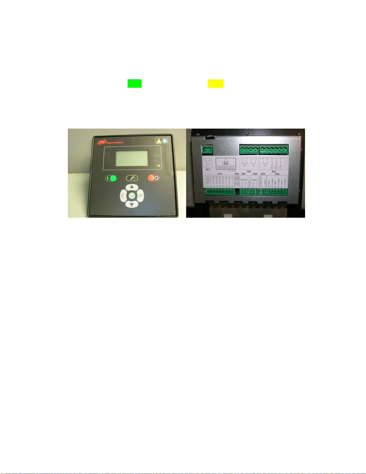
The S3 Intellisys controller is used to control the operations of the air compressor. The following
troubleshooting guide will allow you to troubleshoot the compressor components. The controller will come in
two standard configurations, one is STD (standard) the other is ENH (enhanced). The difference is the options
that are enabled in the software of the controller when the compressor is ordered. If the compressor is ordered
with a standard controller the compressor can be upgraded to an enhanced unit with an upgrade kit CCN
23083637. The upgrade kit includes instruction for retrofitting a standard controller to an enhanced controller.
The controller has 3 analog inputs, 8 digital inputs, 6 relay outputs, 1 analog output and two serial 485
communication ports. The controller has a 24VAC input while the internal power supply is a 24 VDC unit that
must sustain a 40 ms power loss before resetting. The S3 controls all aspects of machine operation including
starting, stopping, loading and unloading, safety shutdowns, and user interface as well as compressor remote
connectivity to other devices.
This controller is different than other Intellisys controllers in that the relay outputs are not solid state triacs,
they are relays that are turned on an off by an internal 24 VDC power supply controlled by the internal
software. There will be no voltage leakage as you find with triacs. So fault finding will be easer due to fact that
if a relay output is on or off due to a problem with the controller simply replace the controller, there are no user
serviceable parts. The analog output (X06 term 1-2) for the PORO horn ( 4-20 Ma output ) simply energizes
the solid state relay when the unit starts after a power outage.
A user interface shows the status of the compressor while it is running. The display uses ISO symbols to
convey information to the operator and it will be necessary to learn the symbols as well as the menu structure to
troubleshoot the compressor. Pass codes are required to enter the Set up Access screen, and Fault History
(0000), and Advanced Set Up (0101). These codes are provided in this manual and the operator’s manuals. This
troubleshooting guide also includes the pass code for the Factory Setup that is to only be used by IR service
technicians and not given to customers (Code is 1954). The next pages give an overview of the buttons on the
controller as well as the ISO symbols and software navigation.
4
Page 5
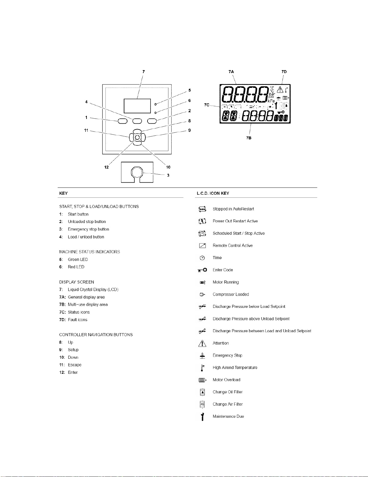
S3 Intellisys Controller Operating Instructions
5
Page 6

Software Navigation
6
Page 7
020 Tr
Motor PTC Open (High Motor Temperature)
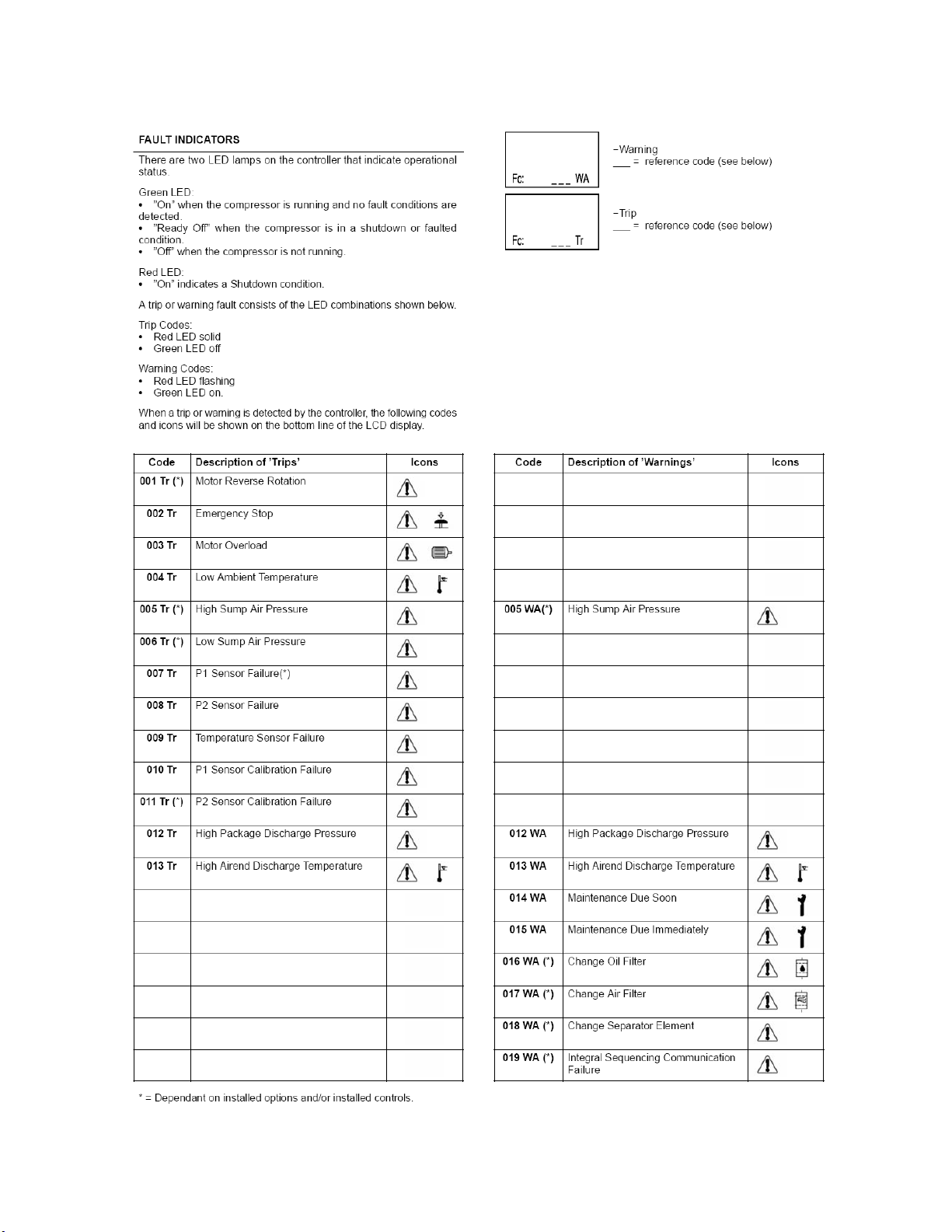
Eiger Controller Fault Indicators
7
Page 8
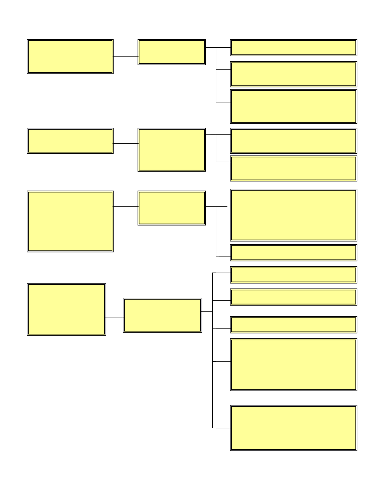
Eiger Fault Finding
’Power on’. L.E.D.
does Not
illuminate.
Intellisys indicates
a tripped condition.
Compressor is
stopped but
Intellisys indicates
that it is still
running (STD
controller only)
Control Voltage
not available
Control Circuit
Interrupted By a
Safety Circuit
Device
Control voltage
not available to
relay inputs
Check the control fuses.
Confirm Incoming Power is correct
voltage
Check the transformer secondary
windings for 24 VAC control
voltage and 110 VAC.
Check machine for indicated fault
and repair.
Attempt to ’reset’ the controller by
removing power to the controller.
Check MCB3 for voltage, Controller
has no power to relay outputs.
This controller has no provision to
detect a power loss to the relay
outputs.
Reset controller
Compressor trips
indicating a high
compressor
temperature.
Fault T 13, W 13
Insufficient Coolant
Circulation,
insufficient cooling.
Check coolant level
Check Temperature sensors
Check thermostatic valve
AC, Check cooling air flow, cooler
restrictions, exhaust vents, inlet
restrictions.
WC, check water flow, strainer,
and water temperature
Excessively high ambient
Temperature / Humidity
(i.e. greater than 46C (115F).
8
Page 9
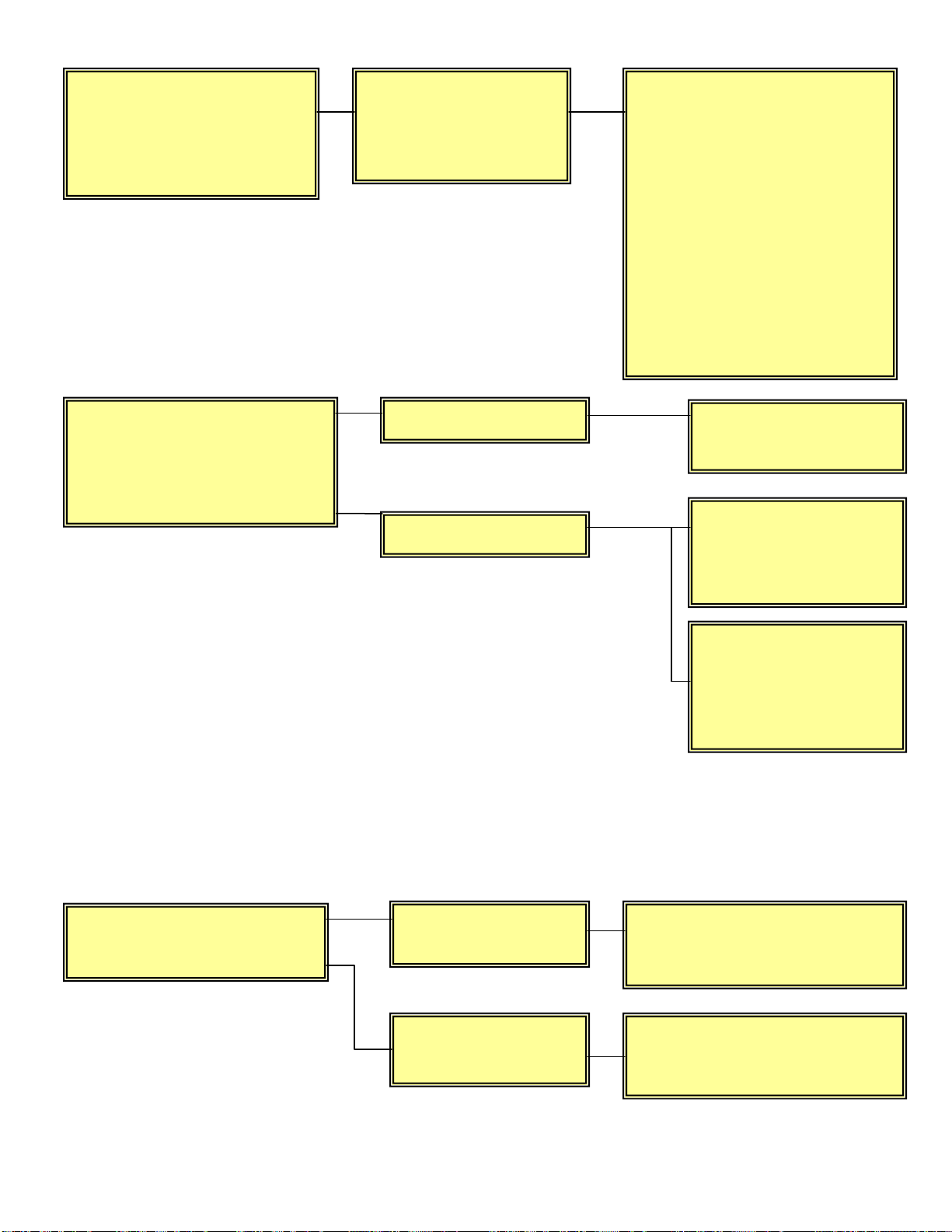
Compressor trips and
indicates motor
overload.
Fault T 3
Excessive current has
caused the motor
overload to trip
Check the actual operating
pressure and lower the
setting if it is too high.
Isolate the electrical supply
and check that the air end
and motor rotate freely.
Check the separator element
for excessive pressure drop.
Set the motor overload on
star-delta at .67 * FLA * SF
of motor name plate data
tag. Measure current at
bottom of MOL
Compressor shutdown
display shows
OVERPRESSURE.
Fault T 12, W 12
Isolation valve
Blowdown system
Open the valve and
restart.
Check the operation of
the load solenoid
mechanically and
electrically
Check the operation of
the unloader valve −
strip and clean if
necessary.
Compressor will not
build up rated pressure.
Air Demand too
high
Offline pressure set
too low
9
Check for leaks, open service
valves or exceptionally high
demand.
Check the offline pressure
setting.
Page 10
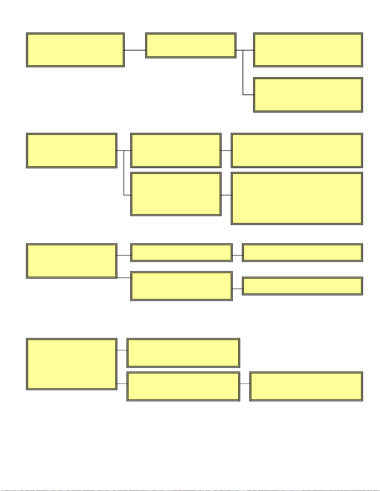
p
Compressor will not
load.
Inlet valve not opening
Check that the valve is free
to open.
Check the operation of the
load solenoid valve 1SV.
Compressor fails to
deliver rated
capacity.
Excessive coolant
consumption.
Check the operation of
the inlet valve.
Check the operation of
the load solenoid valve
1SV.
Blocked scavenge line
Ruptured or fouled
separator element
Check the offline/online pressure
setting.
Check the inlet filter for
contamination. The L.E.D. should
indicate if it is blocked.
(ENH controller only)
Clear the blockage.
Change the element.
Rapid cycling or
receiver will not
blow down to
unloaded running
ressure.
System is not using enough
air, increase consumption.
Minimum pressure valve
(MPV) stuck open.
10
Strip the MPV, examine and
repair if necessary.
Page 11
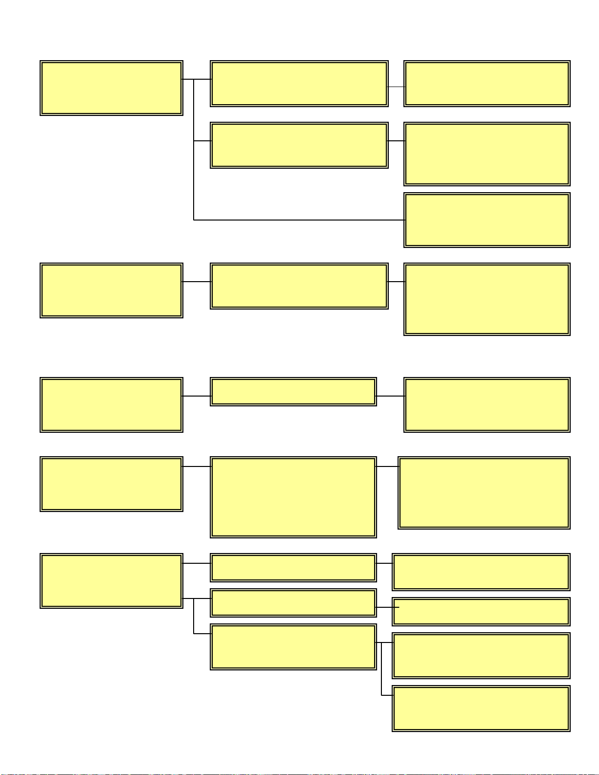
(
)
Safety valve blows
when compressor
loads.
.
Motor reverse
rotation
Fault T 1
Emergency Stop
Fault T 2
Low ambient
temperature
Fault T 4
High sump air
pressure.
Faults T 5, W 5
Minimum pressure valve
(MPV) stuck closed.
Safety valve faulty
Incoming power wired to
package incorrectly
Emergency stop activated
Compressor will not start
below 2 deg C (28 deg F),
unless fitted with low
ambient option (−10_C)
14 deg F
MPV stuck closed Strip MPV, examine and repair
Blocked separator element
Blow down system
ineffective
11
Strip the MPV, examine and
repair if necessary.
Check the setting of the
safety valve and the rated
pressure.
Blocked separator element
Check differential pressure
and replace element
Change any 2 of the
incoming power wires to
change motor rotation
Clear fault hazard twist
emergency stop button to
reset.
Wait until compressor
package air temperature
rises above minimum starting
temp requirement.
Replace separator element
Check the operation of the
load solenoid valve.
Check un-loader valve − strip
and clean if necessary.
Page 12
Low sump air
pressure.
Fault T 6
P1 Sensor Failure
Fault T 7
P2 Sensor Failure
Fault T8
Temperature Sensor
Failure
Fault T 9
P1 Sensor
calibration
failure.
Fault T 10
P2 Sensor
calibration
failure.
Fault T 11
Incoming power wired to
package incorrectly
Check main motor rotation if
incorrect change any two wires
to reverse rotation.
Inlet valve not opening
Check valve and make sure it
operates freely
Check load solenoid valve and
controller operation.
Check wiring to transducer Recalibrate Transducer or
Replace
Controller measured value
is outside of the +/- 10 %
range of the full scale value.
Check resistance using
chart on pages 52-57.
Replace sensor if resistance
does not equal ambient
temp.
Check sensor connection and calibrate or replace if
necessary
Motor PTC Open
(High Motor Temp)
Fault T 20
Check for overload
condition
12
Checking motor cooling
Page 13
Maintenance due
soon.
Fault W 14
Maintenance timer has
reached 1800 hrs of runtime
or 7884 hours clock time.
Reset time in factory set up
menu using access code
1954
Maintenance due
immediately.
Fault W 15
Change oil filter.
Fault W 16
Change air filter.
Fault W 17
Maintenance timer has
reached 2000 hrs of runtime
or 8760 hours clock time
Change oil filter
Change air filter Check air pressure switch
Reset time in factory set up
menu using access code
1954
Check differential pressure
switch for fault
for fault
Change separator
element
Fault W 18
Integral sequencing
communication
failure.
Fault W 19
Change separator element Recalibrate sump pressure
transducer. (3APT)
Wiring or communication
fault
Check wiring
13
Page 14
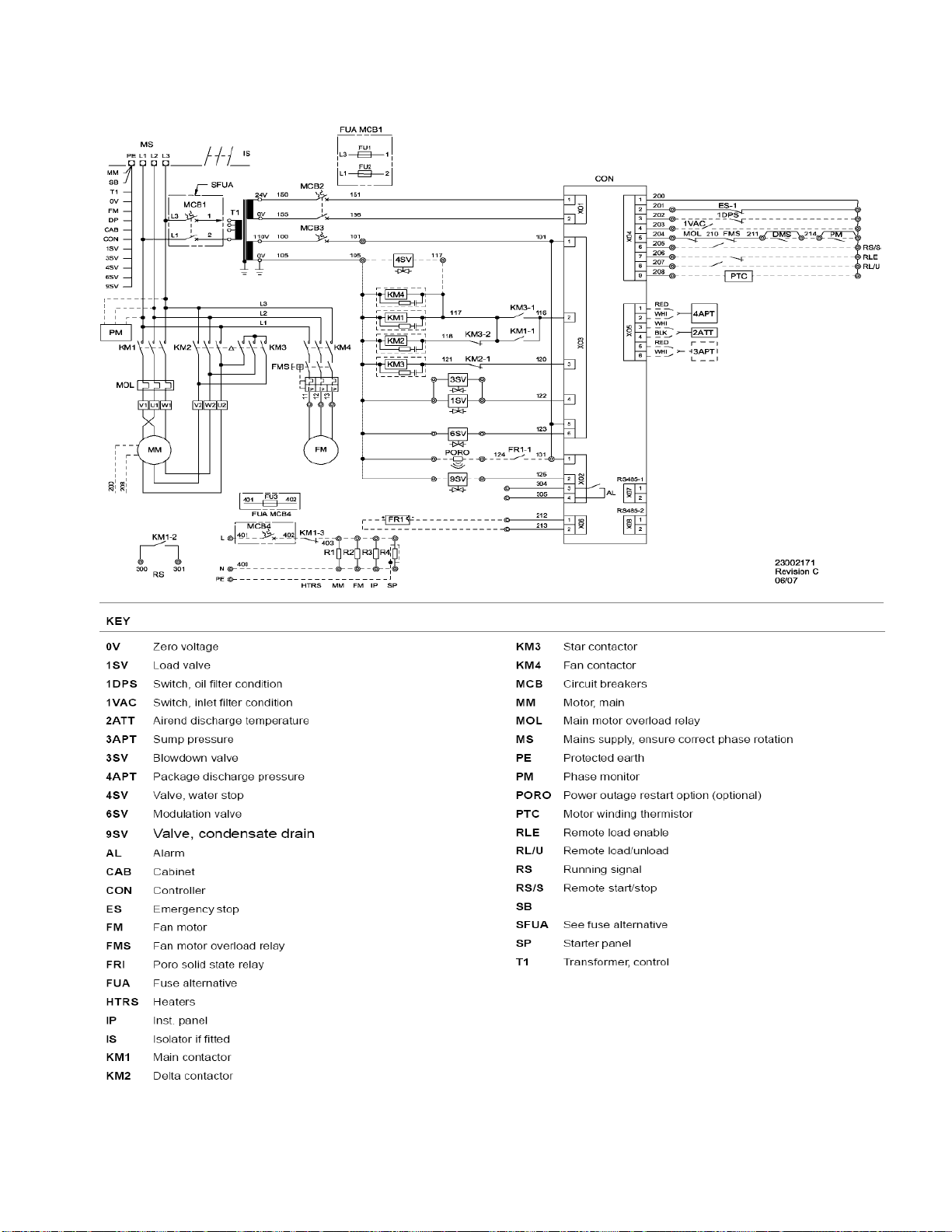
Star Delta Wiring Diagram
14
Page 15
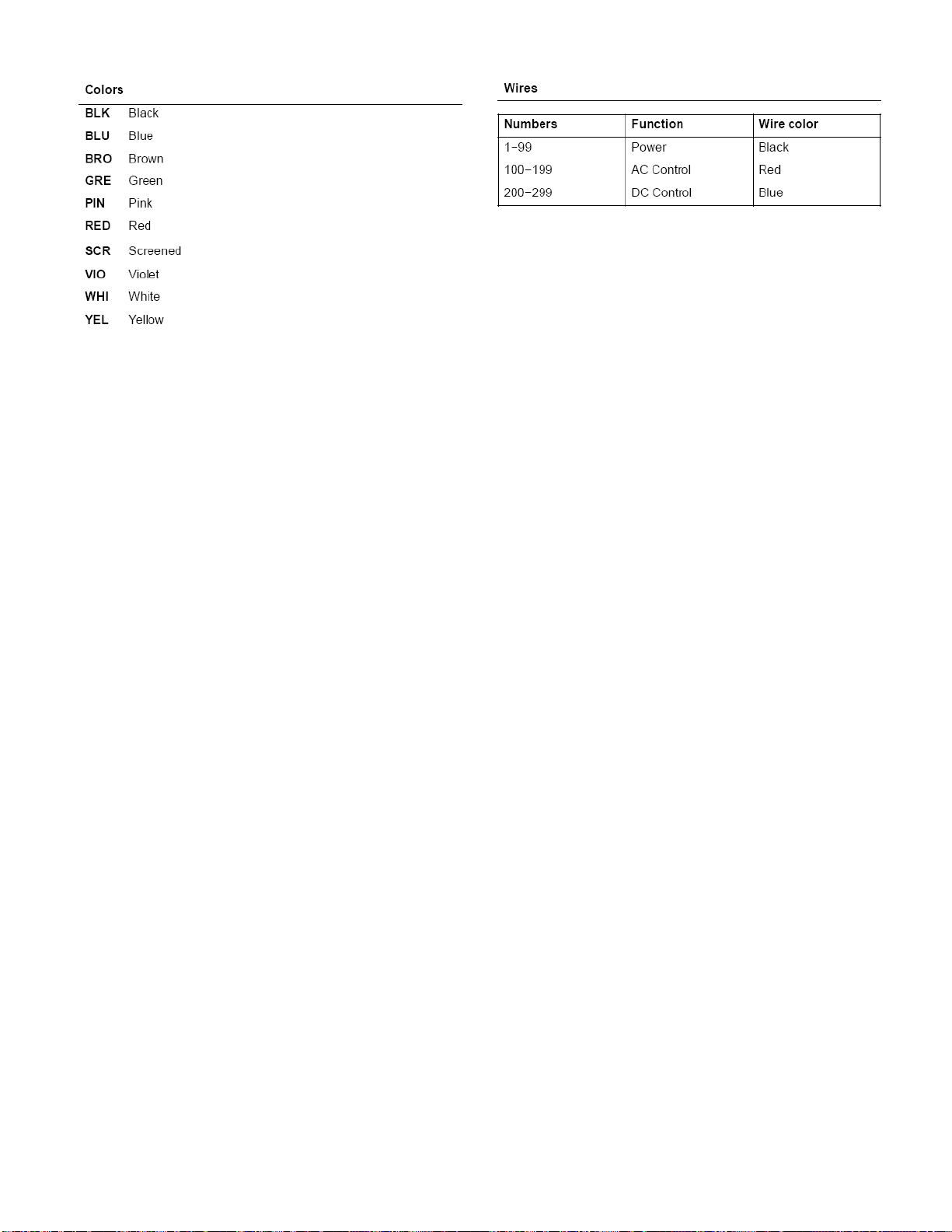
15
Page 16
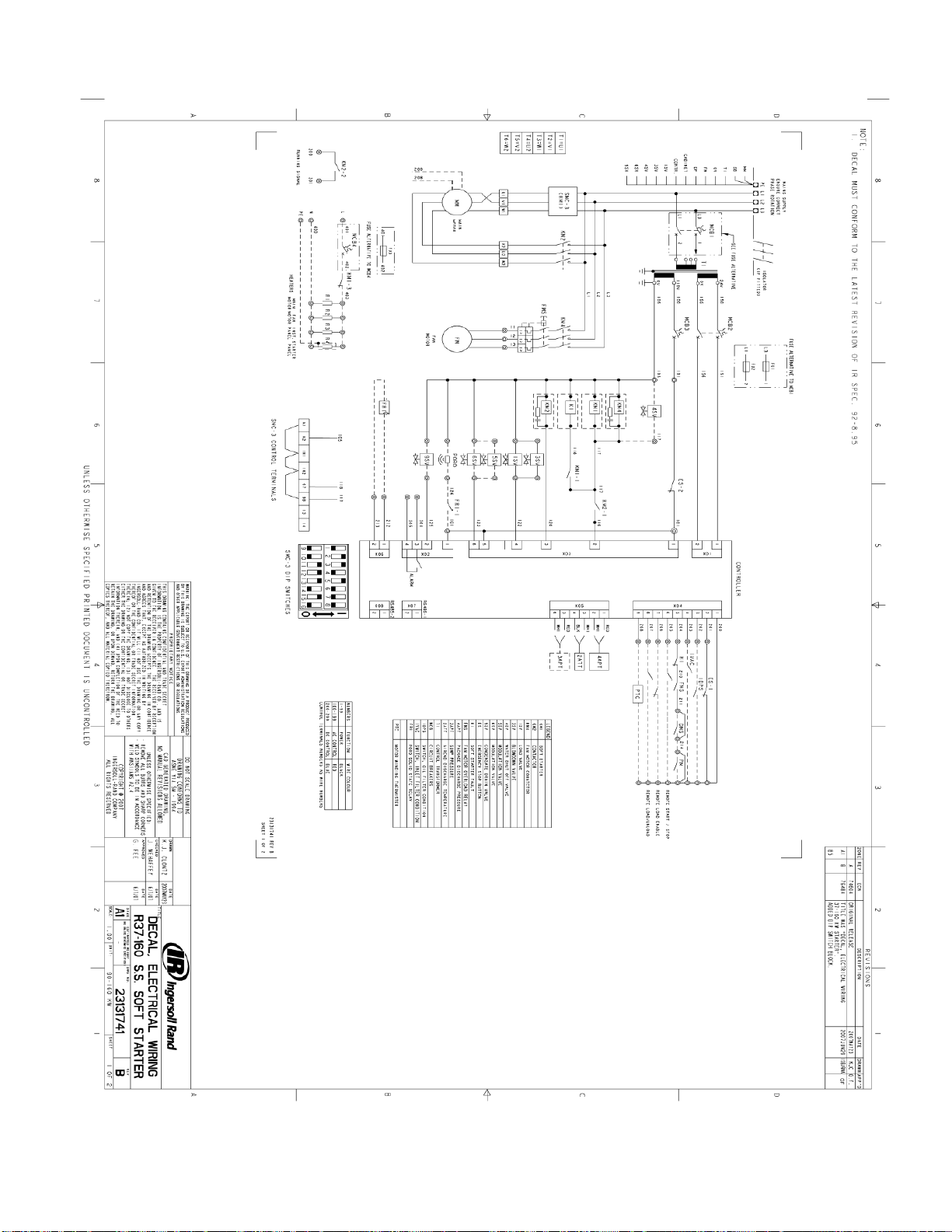
Soft Start Wiring Diagram
16
Page 17
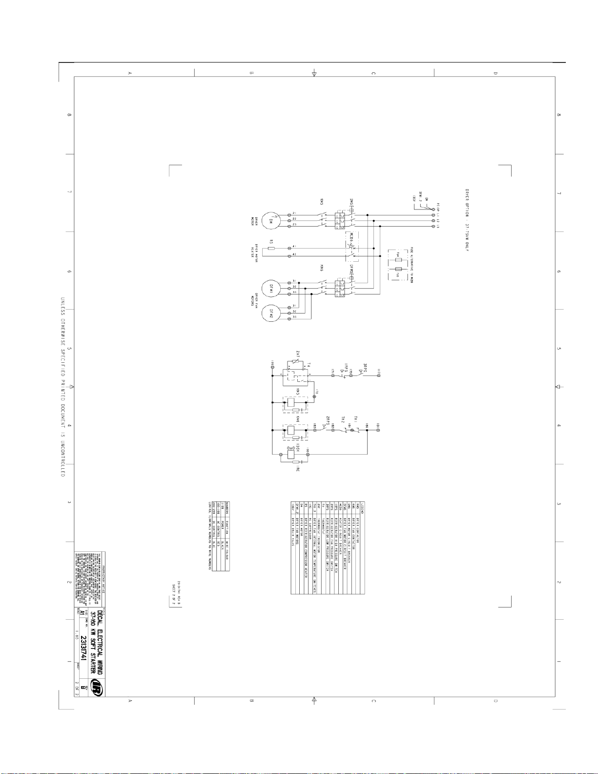
17
Page 18
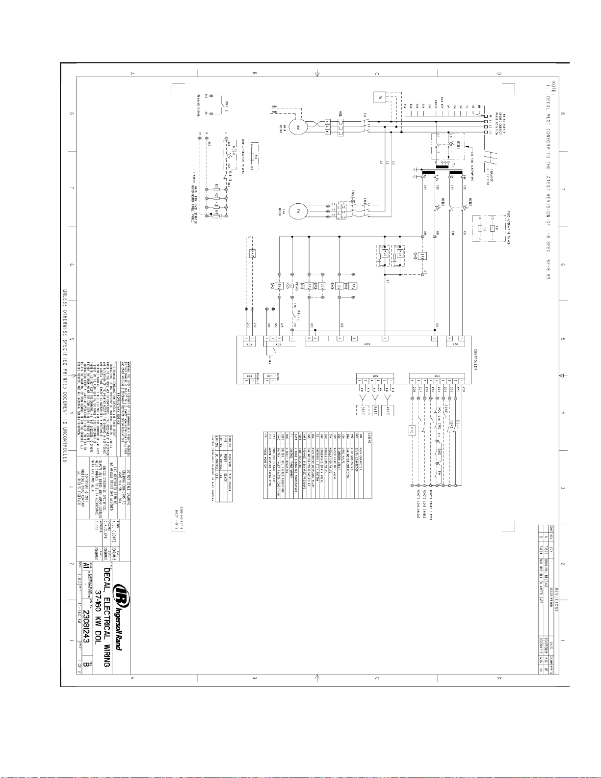
Line Start Schematic
18
Page 19
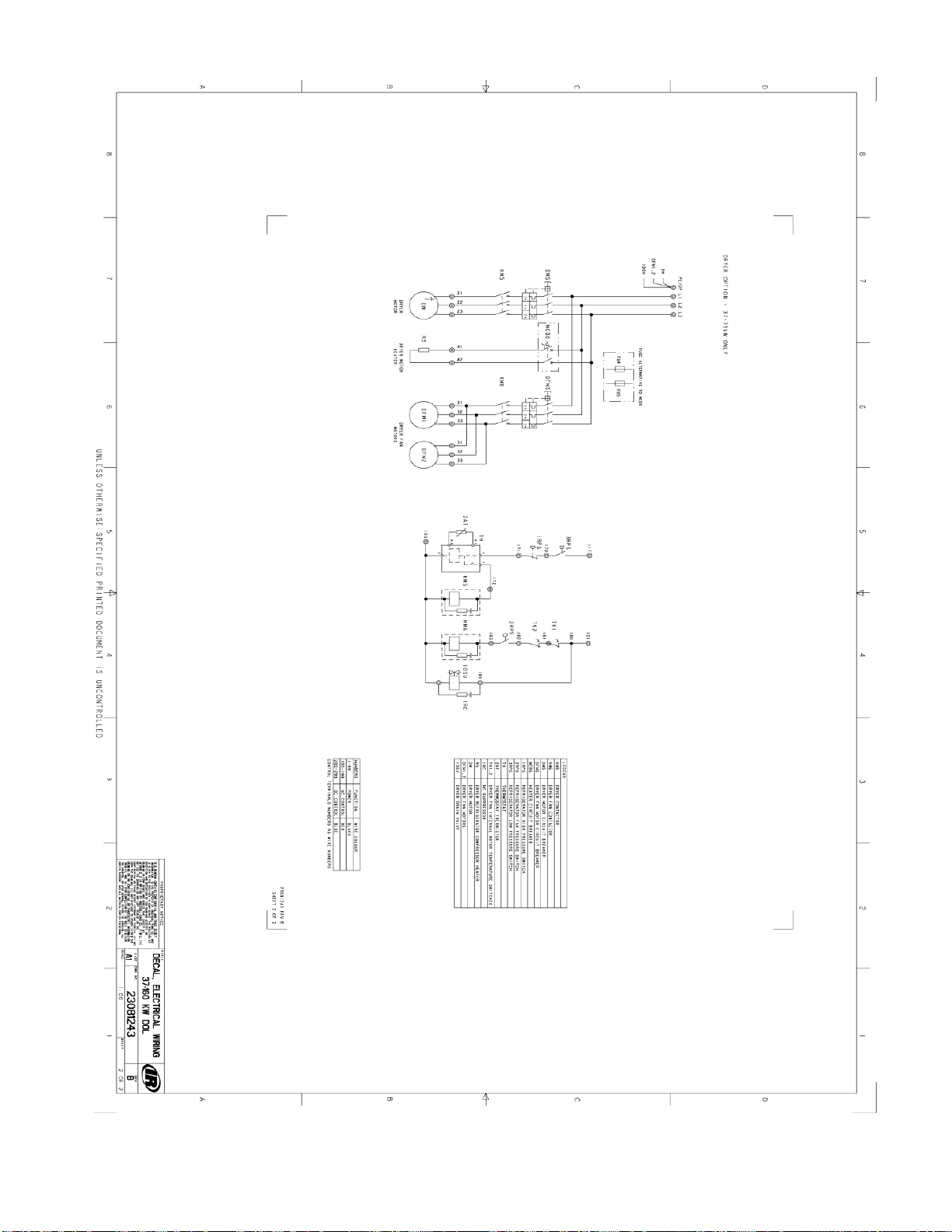
19
Page 20
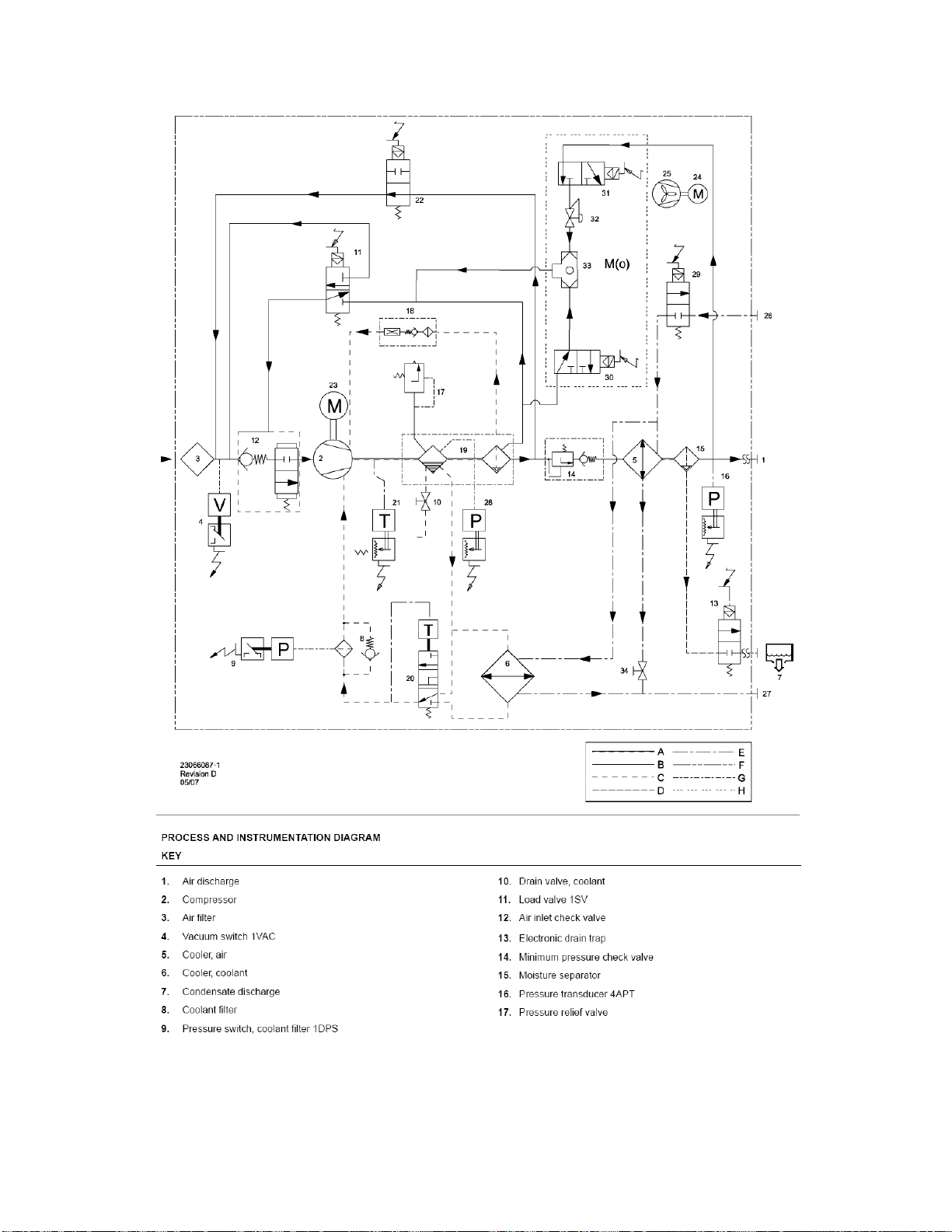
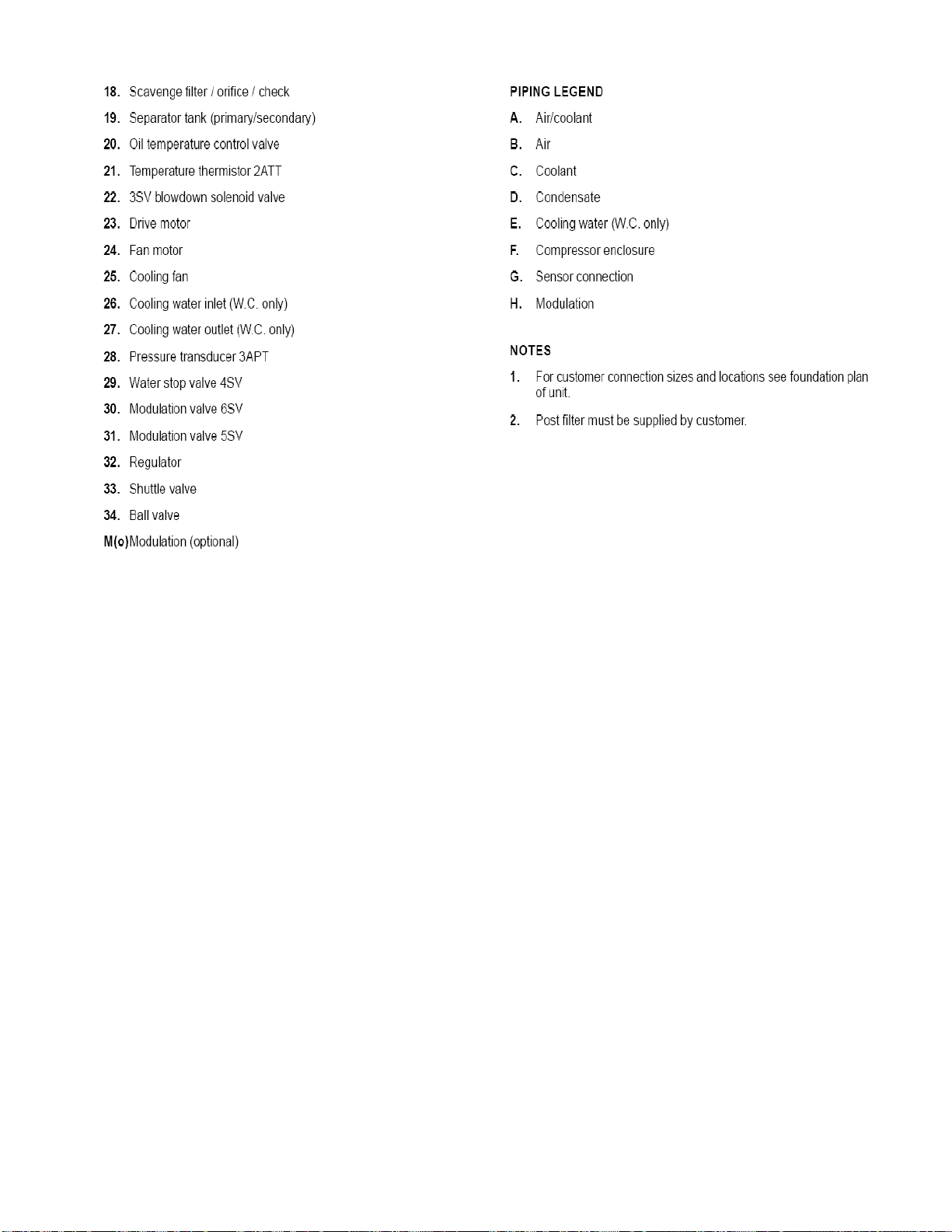
Process and Instrumentation Diagram
20
Page 21
21
Page 22

GENERAL OVERVIEW OF THE COMPRESSOR
The compressor is an electric motor driven, single stage screw compressor, complete with
accessories piped, wired and base plate mounted. It is a totally self contained air compressor
package. The standard compressor is designed to operate in an ambient range of 2_C to 46_C (35_F
to 115_F). The standard maximum temperature of 46_C (115_F) is applicable up to an elevation of
1000m (3280ft) above sea level. Above this altitude significant reductions in ambient temperature are
required if a standard motor is to be used. Compression in the screw type air compressor is created
by the meshing of two (male & female) helical rotors.
The air/coolant mixture discharges from the compressor into the separation system. This system
removes all but a few PPM of the coolant from the discharge air. The coolant is returned to the
cooling system and the air passes to the after cooler and out of the compressor through the moisture
separator (optional).
Air is pulled into the machine by the cooling fan and is pushed through the combined cooler / after
cooler. By cooling the discharge air and passing it through the separator, much of the water vapor
which is naturally present in the air, can be removed.
The coolant system consists of a sump, cooler, thermostatic valve and a filter. When the unit is
operating, the coolant is pressurized and forced to the compressor bearings. The compressor load
control system is automatic ’On−Off line’. This is accomplished by the Intellisys S3 Controller
monitoring the discharge pressure and operating the SV1 solenoid valve. When the load valve is on
(Loading) the blow down solenoid valve SV3 is off and this logic reverses when the unit unloads. The
compressor will operate to maintain a set discharge line pressure and is provided with an auto restart
system for use in plants where the air demand varies widely. Panel instrumentation is provided to
indicate the compressor operating conditions and general status.
CAUTION
LOW DEMAND APPLICATIONS
During periods of low demand, the compressor may not reach its normal operating
temperature. Sustained operation at low demand can result in the build up of condensate in
the coolant. If this situation occurs, the lubricating characteristics of the coolant can be
impaired which may lead to damage of the compressor.
THE COMPRESSOR SHOULD BE ALLOWED AMPLE LOADED RUNNING TIME.
22
Page 23

Input/Output and Alarm Information for
Intellisys S3 Controller
1.0 Hardware Input / Output Information
Each I/O and software function is labeled as STD where the function is available in the standard
controller (Rapidly Developing Economies) and ENH where the function is available in the enhanced
controller (RDE – Options and Developed Markets).
1.1 Analog Inputs - 10 bit resolution. .5% Full scale accuracy. Pressure Transducer, 2 Wire, 4-
20 ma, Loop Powered.
Sensor Range Description Control Term
STD 4APT 0-232 Psi Package Discharge X05 1-2
ENH 3APT 0-232 Psi Sump, Wet Side X05 5-6
Temperature, 2 Wire, 10 K ohm Thermistor, see appendix 1 for Resistance table!
Sensor Range Description Control Term
STD 2ATT -34 to 124 °C (255 F) Air end Discharge X05 3-4
1.2 Analog Output - 0-20ma, 24Vdc, max load 500 Ohms, .020ma resolution,
Output Description Control Term
STD #1 PORO Horn (Using Solid State Relay) X06 1-2
Analog Inputs Comments
STD Pressure Input Calibration - Initiates an automatic calibration routine for reading and
correcting the pressure transducer inputs with a known zero Psi input. A zero offset calibration should
be performed by first the user verifying the pressure applied to the pressure transducer is in fact 0
PSI. Initiating this calibration routine will read and store a new zero offset value for the analog inputs.
This value is used as an offset for all future pressure readings. The display (UI) should indicate to the
user that a zero Psi reading has been successfully made and stored for the new zero PSI offset value
by displaying a successful message or icon. If when reading the analog input for the 0 PSI value, the
actual reading is greater than +/- 10% of the scale, the calibration will not be performed for that
particular sensor and the previous pressure offset value will be retained. A Sensor Calibration Failure
will be displayed indicating which input has failed and also adding an entry into the Alarm Log. If the
Developed Markets features are enabled, the Sump Pressure transducer will be present and should
be calibrated along with the Package Discharge Pressure transducer. Span calibration is not
accessible by the customer. The calibration is done through the advanced set up menu as shown in
the flow chart on page 6.
23
Page 24

1.3 Digital Inputs - 24 Vdc internally supplied source, 200ma max,
DI #1 = 140 ma., DI #2 - #7 = 10 ma., DI #8 = 1.4 ma. typical current.
Input Fault Description Control Term
STD #1 Open Emergency Stop X04 1-2
ENH #2 Closed Oil Filter Condition X04 1-3
ENH #3 Closed Inlet Filter Condition X04 1-4
STD #4 Open Motor Over load (Main, Fan, Dryer) X04 1-5
*ENH #5 Remote Start and Stop X04 1-6
*ENH #6 Remote Load Enable X04 1-7
*ENH #7 Remote Load/Unload X04 1-8
ENH #8 Motor PTC X04 1-9
*IEO and ASC can control the compressors using an ISCII module
connected to digital inputs #5, #6 and #7.
1.4 Digital Outputs - Internal relay, 24 Vdc @ 8 Adc, 240 Vac @ 8Aac
resistive,
Output Description Control Term
Control Voltage Input, DO #1- #3 X03 1
STD #1 Starter Contact 1M X03 2-Comn
STD #2 Starter Contact 1S X03 3-Comn
STD #3 Load / Blowdown Solenoid Valve X03 4-Comn
Control Voltage Input, DO #4 X03 5
ENH #4 Modulation X03 6-Comn
STD #5 Condensate Drain X02 1-2
STD #6 General Alarm Contact (NO) X02 3-4
Digital Output Comments
STD Star Delta Logic Using Two Digital Outputs - Combine 1M / 2M on one common output, a
normally closed electrical interlock (KM3-2) from the 1S (KM3) contactor keeps the 2M (KM2)
contactor from energizing anytime the 1S (KM3) contactor is energized.
Electrical interlocks are wired such that when the 1S (KM3) output is de-energized at Star Delta
transition time causing the 1S (KM3) contactor to open, the 1S normally closed interlock (KM3-2) falls
back to the closed position energizing the 2M (KM2) contactor.
A second electrical interlock from the 1S (KM3) contactor is wired in series with the 1M (KM1)
contactor to insure the 1S (KM3) is pulled in before the 1M (KM1) will be energized. An interlock from
the 1M (KM1) contactor is used to seal around the 1S (KM3-1) contact to allow the 1M (KM1) contact
to remain energized when the 1S (KM3 contact is de-energized at the Star Delta transition.
STD Allen Bradley SMC-3 Soft Start Logic Using Two Digital Outputs
Outputs X03-2 and X03-3 can be configured to operate an Allen Bradley SMC-3 soft starter. The
operating sequence of X03-2 and X03-3, when the soft starter starting method is selected, follows.
X03-3 energizes immediately at the start command. 1/2 seconds later X03-2 energizes. Both outputs
maintain an energized state while the motor is given a run signal. When the motor is given a stop
signal the operating sequence of X03-2 and X03-3 are reversed from the starting sequence.
24
Page 25

STD Common Fault Relay - This is an output provided for customer use. This relay energizes
during normal operation and returns to its Normally Open, N.O., state, when a shutdown or trip
condition is detected. The Fault relay should only toggle when the controller has detected a Shutdown
or Trip (Alarm) condition.
STD Condensate Drain - This is an output provided to control a condensate drain solenoid valve.
This output is a timed output that toggles on for a period of time defined by the Condensate Drain
Time set point. The drain valve remains off for a period defined by the Condensate Drain Interval
Time set point.
Condensate Drain Time Default - 5 Sec
Minimum - 1 Sec
Maximum - 30 Sec.
Condensate Interval Time Default - 180 Sec
Minimum - 90 Sec
Maximum - 300 Sec
ENH Modulation - The modulation output is used to turn on the modulation solenoid valve anytime
the modulation set point is turned on and the machine is in a loaded state. If the modulation set point
is turned off the output remains off.
1.5 Control Power Supply - 24 VAC +/- 20%, 24 VA, 50/60 Hz, Floating -non-grounded, and
the controller must sustain a 40ms power outage before resetting.
Input Description Control Term
Supply Controller Power X01 1-2
I/O Functionality
STD Contact De-bounce Times are not adjustable and are for information only. .
Dig Input #
1 50 ms
2 15 sec
3 15 sec
4 2 sec
5 2 sec - Closed
.5 sec - Open
6 50 ms
7 50 ms
Delay Time
STD Combine MOL FOL into a common digital input called Motor Overload. Overload contact
current must be minimum 17vdc and 5 ma.
ENH Remote Start / Stop using a single contact.
25
Page 26

1.6 Intellisys S3 Serial Communications - RS-485, 500 to 1000 Meters
Port Description Control Term
ENH Port #1 Integral Sequencing, X4I, X8I X07 1-2
CMC Multi-485, Serial Programming
ENH Port #2 Remote Monitor / Control, X08 1-2
Modbus RTU
STD Port#2 Modbus Read Only X08 1-2
Serial Communications Comments
ENH Serial Port #1 - S1 Integral Sequencing, X4I, X8I, Hardware - RS485, 2 Wire Half Duplex,
Opto-isolated, and capable for communicating up to 4000 ft from a host device. Software - CMC
Multi-485.
ENH Serial Port #2 - IEO, ASC, Remote Monitoring and control of the compressor. Hardware -
RS485, 2 Wire Half Duplex, Opto-isolated,and capable for communicating up to 4000 ft from a host
device. Software - Modbus Slave, RTU, Selectable Baud Rate, 2 Stop bits, 8 Data bits, No Parity.
Modbus Baud Rate - Selectable from any one of the following standard Baud rates. 1200, 2400,
4800,9600, 19200, 38400, 57600, 76800, 115200.
Modbus Registers - See Paragraph 13 “Modbus Register Listing” for the compete register listing
with detailed descriptions. Modbus Commands Supported - At a minimum Modbus 03 Read Holding
Register, and 06 Preset Single Register.
This serial port must be capable of connecting to a multi-drop, RS485 network with up to 32
devices functioning as a Modbus Slave only. This serial port will be exposed to all Modbus network
traffic intended for any device on the network. Serial communication handling must not hinder safe
and timely machine control. The serial port should be capable of servicing communications at least
twice per second. Any serial communications intended for this slave device must be responded to
within 500 milliseconds.
ENH Serial Control - Starting the compressor using serial communications can be accomplished
only if RC, Remote Control, is set to Modbus control. See Section12
For Modbus control commands to operate, the Status Register (1) bit 0 must be set High for all
Status Register write commands to enable and maintain Host control. To remain in Host control
mode, serial communications (any serial communication) must be maintained with a maximum of 2
seconds between communications. If for any reason serial communications is lost (not accessed
within 2 seconds), the compressor reverts to Local control and continues to run using the local set
points.
The compressor is started by placing the compressor in Host Control, Status Register 1, bit 0 to a
1 (Host), and bit 1 to a 1 (Run) or a Hex 03 command. This will start the compressor and place it in a
run condition. If the pressure is such that the compressor needs to run (depending on the mode of
operation) the compressor will start and run until the compressor no longer needs to run to maintain
pressure. When the compressor is in a run mode, but no longer needed to make air, the compressor
motor will be stopped in “Auto Restart” but will restart any time air is needed. Local Control stopping
should always remain active and of the highest priority for safety of the compressor. If the compressor
is stopped locally, all remote control operation is cancelled The Units of Measure for the Pressures
read serially will always be read in PSI and temperatures in Deg F.
26
Page 27

1.7 Remote Control The compressor will not automatically restart after a power failure unless a
PORO kit is installed. The compressor can be restarted using the Green start button only if the
compressor is getting a remote run command.
1,8 Auto Stop Timer The auto stop timer has a range of 30 to 360 seconds. Zero (0) can be
selected, which will prevent the motor from stopping. The machine will only load/unload without ever
stopping the motor.
1.9 Eiger Maintenance Intervals
STD Multiple level maintenance intervals
STD 150 Hours Runtime -150 Hrs after the initial start-up of the compressor, one time timer.
STD 2000 Hours Runtime - 2000 hours of compressor runtime since the last maintenance timer reset.
STD 8760 Hours Real Time Clock Time - (1Yr) after initial startup of the compressor or after the
maintenance timers have been reset.
STD Maintenance Indicator - How to display time to maintenance; the maintenance timer will display
the maintenance timer value in hours and in percentage, (2000 or 8760) closest to reaching its
respective predetermined maintenance interval time. Once the maintenance timer value reaches 10%
(or 90%) of the preprogrammed time, (1800 hrs of runtime or 7884 hours clock time) the Wrench Icon
will flash. Once the maintenance timer value reaches 0% (or 100%) of the preprogrammed time,
(2000 hrs of runtime or 8760 hours clock time) the Red LED will flash (Warning) and wrench icon
should be on continuously and remain on until maintenance is performed and the timers are reset.
STD Reset Maintenance Timer - Once service has been performed the Maintenance Timer values
can be reset by entering the Factory Setup Menu and scrolling to the Maintenance Timer Reset
screen and performing the reset. If for any reason a time other than 2000 hours needs to be entered it
can be done in the Maintenance rest menu. Simply set the hours wanted and press enter.
27
Page 28

Maintenance
28
Page 29

Maintenance
29
Page 30

Maintenance
30
Page 31

S3 Controller Input/Output Overview
AI = Analog Input
DI = Digital Input
DO = Digital Output
31
Page 32

S3 Fault Descriptions
2.0 Faults An Intellisys S3 – A WARNING will not shutdown the compressor. The warning will
remain on the display until acknowledged. It can be cleared by pressing the “C” clear key. A log will
be retained of the warnings / trips that have occurred. An Intellisys S3 TRIP will shutdown the
compressor and must be manually cleared by pressing the “C” clear key. The trips will remain on the
display until acknowledged. The trips displayed will take precedence over the warnings. A log will be
retained of the warnings / trips that have occurred.
Trip Faults Comments
ENH Motor Reverse Rotation - Sump pressure has not indicated a positive pressure, 2 seconds
after the machine has loaded, first time after a power-up. This time is increased to 6 seconds if the
soft starter option is turned on. Once correct motor rotation is verified, this is not checked again until
power is removed from the controller.
STD Emergency Stop - Emergency Stop low level contact has opened.
STD Motor Overload - Main motor or Fan motor Overload contact has opened.
STD High Package Discharge Pressure – refer to table in section 12 - (Not Adjustable, Information
Only)
STD High A/E Discharge Temperature - refer to table in section 12 - (Not Adjustable, Information
Only)
STD Low Ambient Temperature - The air-end temperature sensor is measuring a temperature less
than 2°C. The compressor will be in an alarm state and not start if the temperature is below 2°C. The
compressor will start if the temperature is above 2°C. This is only active if Low Ambient, LA, option is
installed.
ENH Low Sump Air Pressure - The sump air pressure has not increased above 15 psi. This is
measured 15 seconds after starting and operational anytime the compressor is running.
ENH High Sump Air Pressure - refer to table in section 12 (Not Adjustable, Information Only)
STD Discharge Pressure Sensor Failure - The discharge pressure sensor input reading is beyond
the normal measurement range below 3.4 ma or above 20.8 ma.
ENH Sump Pressure Sensor Failure - The sump pressure sensor input reading is beyond the
normal measurement range below 3.4 ma or above 20.8 ma.
STD / ENH Sensor Calibration Failure - A sensor calibration has been attempted and the measured
value is outside of the +/- 10 % Full Scale value.
ENH Motor PTC Trip The motor TC is open due to high motor Temperature.
Warning Faults
STD High Package Discharge Pressure - refer to table 12 (Not Adjustable, Information Only)
ENH High Sump Pressure – refer to table 12 (Not Adjustable, Information Only)
STD High Air end Discharge Temperature - refer to table 12. (Not Adjustable, Information Only)
STD Maintenance Due soon - refer to table 12 (Not Adjustable, Information Only)
STD Maintenance Due immediately - refer to table 12 (Not Adjustable, Information Only)
ENH Change Oil Filter -
ENH Change Inlet Filter -
ENH Change Separator Filter -
ENH Integral Sequencing Communication Failure -
32
Page 33

Fault History
STD Retention of Fault History last 15 trip and warning faults with compressor information.
Real Time Clock
STD The real time clock will be used to count down the 8760hrs before maintenance. This time is
reset when the maintenance hour indicator is reset. The customer can not view the clock.
User Interface
Buttons - The 8 buttons located on the controller are to be a raised membrane button used to
activate the membrane switch. The icon and button oval are not raised.
Fault Symbols
LED Indicators - Green - On when the compressor is running and no fault conditions are detected.
“Ready” Off when the compressor is in a Shutdown - Faulted condition. Off when the compressor is
not running.
Red - Flashing indicates a Warning condition. (Along with the Green LED still illuminated). On Solid
indicates a Shutdown condition.
33
Page 34

S3 Intellisys Operator Display Icons
The backlight for the LCD should be left on all the time as long as this does not significantly reduce
the life of the backlight.
Icons in the standard LCD display:
--------------------Shutdown in Auto Restart (Pressure Control)
-------------------Power Out Restart Active (PORO)
-------------------Scheduled Start / Stop Active
------------------Change Air Filter Warning
------------------Change Oil Filter Warning
34
Page 35

Status Display - When power is applied to the controller the LCD check will
be performed for 3 seconds and the Controller Software
Version will be displayed.
Status Icons indicating machine operational or fault status will be continuously displayed for all Status
displays.
Compressor Running Unloaded
(Manual Unloaded)
Compressor Running and Loaded
(Flash Icon when the compressor is
Unloaded due to pressure)
Remote Control Active
Disch Press Below Load Set point
Disch Press Between Load and
Unload Set points
Disch Press Above Unload Set point
Stopped Auto Restart
35
Page 36

PORO Active
I(Arrow to point to the left)
Scheduled Start / Stop Active
Pressing the Up and Down arrow buttons will toggle through the following items to be displayed in the
Multi-use display area. If no buttons are pressed within 30 seconds, the display should revert back to
the default display item. Package Discharge Pressure with Units should be continuously displayed for
all Status and Setup displays.
Satus screen Data in Yellow will only be displayed is ENH
Default Ae: 0 0 0 0 °C Airend Discharge Temp
(1) Ip: 0 0 0 0 PSI Sump Pressure
(2) DL: 0 0 0 0 PSI Delta pressure DL will not be displayed while running unloaded
(3) Rn: _ _ _ _ 000 Run Hours ------------------------------------------
(4) Ld: _ _ _ _ 000 Load Hours -------------------------------------------
(5) Mn _ _ _ _ 000 Maintenance Hours (before Maintenance due) -
(6) Mn _ _ _._ Maintenance % (% of hours before Maint due) ---------------
(7) IS_ _ _ _ Displays the number of hours before Sequencing occurs if IS is enabled
Setup screen Data in Yellow will only be changeable in an ENH controller. The data will be viewable
in a STD controller.
36
Page 37

Setup Display - The Setup Display is entered by pressing the Menu button while the compressor is
not running mode. The Setup display can be exited by pressing the Clear button. A security code of 0
0 0 0 will be required to enter the Setup Display.
CD: 0 0 0 0 Pass Code
If no buttons are pressed within 30 seconds, the display will revert back to the default Status display
item.
Un: 0 0 0 0 PSI Unload Pressure -------------------------------------------
Ld: 0 0 0 0 PSI Load Pressure --------------------------------------------
As: 0 0 0 0 SEC Unloaded Run Timer ------------------------------
Md: _ _ _ _ On_ Modulation On/Off ------------------------------------------
Eu: _ _ _ _ _°C Engineering Units
Dt: 0 0.0 0 _00 Current Date
Tm: 0 0:0 0 _ _ _ Current Time ------------------------------------------
Setup screen Data in Yellow will only be changeable in an ENH controller. The data will be viewable
in a STD controller.
37
Page 38

Trip History Menu - The Trip History display is entered by pressing the Up arrow from the Setup
Menu display. The display will default to the most recent Trip and will automatically cycle through the
recorded values. The last 15 Trips will be recorded. The Trip History can be cycled through by
pressing the Up and Down arrows to select the desired Trip for viewing. The Status Icons should be
displayed as the recorded status
he machine was in when the Trip occurred. The following information will be automatically scrolled
through for each Trip.
Fc: _ 0 0 1 _ _ _ Fault Code
Pd: _ _ 6 5 PSI Package Discharge Pressure
Ae: 2 2 1.0 °F Airend Discharge Temperature
Rn: _ _ _ _ 1 2 3 Run Hours
Sp: _ _ 6 9PSI Sump Pressure
Dt: 1 0.3 0 _06 Date
Tm: 1 0:0 5 Time
Advanced Setup Menu - If the Password entered in the Pass Code entry screen is 0 1 0 1, the
Trip History display is entered by pressing the Up arrow from the Shutdown History display.
Pd: _ C A L _ OK Package Discharge Pressure
Transducer Calibration
Ip: _ C A L _ OK Sump Pressure Transducer
Calibration
: 0 0 0 0 SEC Star Delta Time --------------------------------------------
Sf: 0 0 0 0 SEC Soft Starter Time ---------------------------------------------
Cd: 0 0 0 0 SEC Condensate Drain Time -------------------------------------------
Ci: 0 0 0 0 SEC Condensate Interval Time -----------------------------------------
Sd: 0 0 0 0 Service due Timer --------------------------------------
Ss: _ _ _ _ OFF Scheduled Start Stop --------------------------------------
On/Off
38
Page 39

St: 0 0:0 0 _ _ _ Scheduled Start Time -----------------------------
Sp: 0 0:0 0 _ _ _ Scheduled Stop Time ----------------------------
Po: off PORO on/off --------------------------------------
Pt: 0 0 1 0 SEC PORO Time -----------------------------
Lt: 0 0 2 0 SEC Low Ambient Load Delay Time --------------------------------
RC: 0 0 0 0 _ Remote Control Selection -------------------------------------
Is: _ _ _ _ OFF Integral sequencing --------------------------------------
Cn: 0 0 0 1 Multi 485 Compressor # -------------------------------------
Ad: 0 0 0 1 _ _ _ Modbus Address --------------------------------------
Bd: _ _ _ 9 6 0 0 Modbus Baud Rate --------------------------------------
39
Page 40

Fault Indicators- Trips - Red Trip LED on solid, green LED off. When a trip or warning is
detected by the controller, the following codes and icons should be displayed on the bottom line of the
LCD display.
T Indicates Trip
T20 Motor PTC Trip
40
Page 41

Warnings - Red Alarm LED flashing, green LED on
W Indicates Warning
Environmental Requirements -
continuously in ambient temperatures between 35°F (2°C) and 115°F (46°C) with non condensing
humidity from 0-95% from the front of the controller. The temperature at the rear of the controller can
reach 60C.
All units shall be designed such that the package can operate
41
Page 42

EIGER OPTIONAL FEATURES
STD Low Ambient - The low ambient kit is designed to protect the compressor when starting in
temperatures below 2° C. The temperature is measured at the air-end discharge. The temperature is
read using the standard Air-end temperature sensor. When the Low ambient option is installed and
selected and the A/E Discharge Temperature is measured to be below 2°C, the compressor will be
started when commanded but will delay to load a period of time defined by the Low Ambient Delay
Time, Section 12. This will allow the coolant temperature to rise above an allowable level before
loading the compressor in cold environments. When the Low ambient option is not installed the
machine will not start if the A/E Discharge Temperature is below 2°C. The machine will trip on a Low
ambient fault. This trip will be logged in the fault table. The user can re-start the compressor by
holding the start button in for 10 seconds. Each time the compressor faults on a Low Ambient trip the
customer will have to manually restart and the trip will be recorded in the fault table.
STD Power Out Restart - At loss of power to the machine, a software or hardware flag is set
indicating the operational status of the compressor. Once power returns, the flag is evaluated and the
compressor is returned to its previous operational state. PORO when enabled will be active in all
Local and Remote control modes of the compressor. For PORO to execute, the PORO option must
be installed and the PORO enable must be set to ON in the factory set-up menu. The customer then
has visibility to turn off/on and set the time delay of the PORO option in the advanced set-up menu.
Assuming this is the case, if power is lost to the compressor while the unit is running or is stopped in
auto start/stop, the control will store in memory the current operating conditions.
When power returns to the unit, the control will first verify the PORO option is installed, enabled and
turned ON. Next the control will check to see if the unit was running or stopped in auto start/stop
when power was lost. If it is determined this was the case, it will start the PORO sequence. The
control will energize the PORO horn and start a count down on the display. The RED light will flash
indicating a Warning condition and the horn will blow for the number of seconds (see table 12) the
operator set in the PORO time set point. At the end of the count down the horn will stop blowing and
the compressor will start. The PORO count down can be stopped at anytime by pressing the Stop /
Reset button on the user interface. Pressing any button will cause the horn to stop blowing and the
count down to stop. The control will power up normally in a ready to start mode. If unit is being
operated using remote control, the compressor will not automatically restart after power returns if
PORO kit is not installed.
ENH Scheduled Start / Stop - This is an auto start / stop mode of operation based on the Real
Time Clock current time. A Scheduled Start Time set point is used to automatically start the
compressor when the current time equals the Scheduled Start Time entered for the set point. A
scheduled Stop Time set point is used to automatically stop the compressor when the current time
equals the Scheduled Stop time entered for the set point. This mode of operation can be turned on
and off by selecting the desired mode in the Scheduled Start Stop
On/Off Set point, When Scheduled Start/Stop is turned on and the current time equals the Scheduled
Start Time set point, and the compressor is
not currently running, the compressor will automatically activate the output for the PORO horn for 10
seconds (hard coded) to warn anyone in the surrounding area that the compressor is about to start.
The UI will display a Warning message “Scheduled Start in X seconds”. X is a countdown from 10 to
0 seconds. After 10 seconds the compressor will automatically start as long as the compressor is not
in a Fault condition or manually stopped by pressing the Stop / Reset button. When Scheduled
Start/Stop is turned on, and the current time equals the Scheduled Stop Time set point, and the
compressor is currently running, the compressor will automatically stop. The compressor can
42
Page 43

manually be re-started by any of the standard starting methods. Pressing the control panel start
button, or if Remote Control has been turned on, closing the Remote Start signal or sending a serial
start command.
ENH Integral Sequencing - It will be possible to sequence three Intellisys controllers without a
system controller. This is possible through a cable connecting, up to three Intellisys S3 controllers,
and using one of the controllers as a system controller.
MODULATION CONTROL OPTION
Modulation hardware extends the control types to Modulation (capacity control) and Automatic
Control System when the compressor switches between ’On/Off line’ and modulation as demand
varies. Safety of operation is provided for as the compressor will shut down if excessive
temperatures, electrical overload conditions, or system over pressure should occur.
For those plants which have relatively high constant air demand relative to the compressor capacity,
the recommended control mode is modulation. The modulation control system retains the features of
the on-line / off-line control, but also provides for throttling of the inlet flow up to the off-line air
pressure set point value. By applying line pressure to an adjustable modulator valve, the throttling
position of the inlet valve is controlled, thus allowing the modulator to ”trim” the inlet valve position as
dictated by the line pressure.
The modulating pressure range is about 0.3 bar (4.0 psid) and the modulator normally should be set
to straddle the compressor rated pressure. Modulation begins when the line pressure reaches about
99 percent of the compressor rated pressure and continues as/if the line pressure rises. Modulation
becomes stable when the compressor output equals the plant air demand. When the modulation is at
the factory setting, the maximum capacity reduction will be approximately 60 percent of the
compressor rated capacity (as indicated in Figure 1).
43
Page 44

MODULATE CONTROL VALVE ADJUSTMENT
Ensure that the compressor is isolated from the compressed air system by closing the isolation valve and
venting pressure from the drip leg. Ensure that the main power disconnect switch is locked open and tagged.
1. Put the compressor in the MODULATION mode.
2. Connect a pressure gauge to outlet port of modulation valve with 1/4” tubing tee.
3. Loosen the adjustment screw locknut and back out adjusting screw 3 turns. See Figure 2
4. Put the main power disconnect switch in the ON position.
5. Open the isolation valve and start the compressor.
6. Adjust the isolation valve to bring the discharge air pressure to the rated discharge pressure (100, 125, or
140 psig).
7. While maintaining the rated discharge pressure, turn the adjustment screw on the modulation valve (see
Figure 2) so that the test pressure gauge reads:30 psig for modulate 60% capacity Tighten the adjustment
screw locknut.
8. Press UNLOADED STOP. Wait for sump pressure to go 0 psig.
Close the isolation valve or vent off all system air.
9. Put the compressor in the desired control mode.
10.Remove the test pressure gauge and replace 1/4” plastic plug.
Table 12
44
Page 45

Standard S3 Menu Structure and Parameters
Table 12
45
Page 46

Standard S3 Menu Structure and Parameters
Table 12
46
Page 47

Standard S3 Menu Structure and Parameters
Table 12
47
Page 48

Standard S3 Menu Structure and Parameters
Td – Air Temp High Level Trip Fixed Value 109 C 109 C 109 109
Table 13
48
Page 49

Modbus Register Listing
49
Page 50

Table 13
Modbus Register Listing
50
Page 51

Motor PTC Open (High Motor Temperature)
Here is a list of trip codes that are very handy to carry with you on a service call.
51
Page 52

Appendix 1 Thermistor 2ATT -34 to 124 °C (255 F) Air end Discharge
52
Page 53

53
Page 54

54
Page 55

55
Page 56

56
Page 57

57
Page 58

General Specifications for Eiger Packages
58
Page 59

59
Page 60

60
Page 61

61
Page 62

62
Page 63

63
Page 64

64
Page 65

65
Page 66

66
Page 67

67
Page 68

68
Page 69

69
Page 70

70
Page 71

71
Page 72

72
Page 73

73
Page 74

74
Page 75

75
Page 76

76
Page 77

77
Page 78

78
Page 79

79
 Loading...