

Page 1
Form P7373
04576070
Edition 2
June 2009
Random Orbital Sander
Model R025A–CFS
Installation and Maintenance
Information
Save These Instructions
Page 2

Product Safety Information
CAUTION
Ingersoll Rand No. 10 Ingersoll Rand No. 68
Lubricator
Branch Line 2 times
Air Tool inlet size
Drain Regularly
Regulator
Filter
Compressor
Main Lines 3 times
Air Tool inlet size
To Air
Tool
To Air
System
Intended Use:
A Rotary Air Sander, Polisher or Buer is a compressed air powered, hand-held, rotary power tool equipped with a exible pad or drum
that is driven in a rotary or rotary/orbital motion. A Sander has a ber disc or abrasive paper attached to the pad or a band attached to
the drum and is used for material removal. A Buer will have softer material such as a bung wheel or polishing bonnet attached. A
Polisher is a buer that is used with a polishing compound. A guard is not supplied for these tools.
For additional information refer to Safety Information Manual Form 04580387.
Manuals can be downloaded from www.irtools.com.
Lubrication
This tool is designed to operate without air line lubrication. Introduction of a lubricant with a standard lter/regulator/ lubricator will not
aect tool life.
After each 160 hours of operation, inject one or two strokes of
Ingersoll Rand No. 68 Grease thru threaded end of Spindle (27)
for lubrication of needle bearing contained in Counterbalance (26).
Sanding pad must be removed from Spindle to allow injection of
grease.
Installation
Air Supply and Connections
Always use clean, dry air at 90 psig maximum air pressure. Dust–corrosive fumes and/or excessive moisture can ruin the motor of an air
tool. An air line lter can greatly increase the life of an air tool.
Make sure all hoses and ttings are the correct size and are tightly
secured.
Do not mark any nonmetallic surface of this tool with customer
identication codes. Such action could aect tool performance.
(Dwg. TPD905–1)
2 04576070_ed2
Page 3
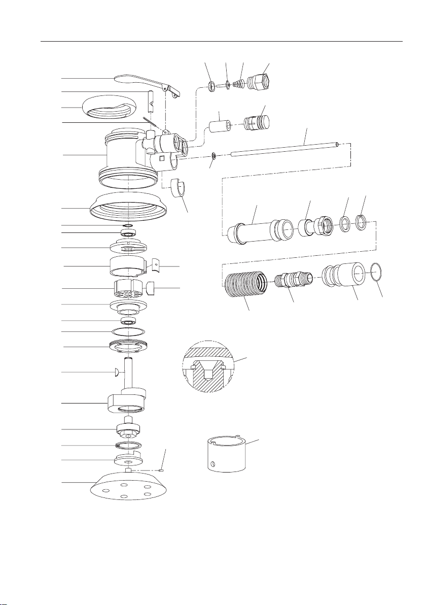
R025A–CFS Series Random Orbital Sander Exploded View
3
2
5
4
1
12
13
14
15
16
18
20
14
21
22
23
24
25
26
41
28
13
31
29
30
40
3536
37
34
11
9
876
39
33
10
38
32
27
17
19
(Dwg. TPA1667)
04576070_ed2 3
Page 4

R025A–CFS Series Random Orbital Sander Parts List
Item Part Description Part Number Item Part Description Part Number
1 Housing (includes pin) 04561429 23 Key 39442
2 Valve Stem 48065–2 24 Counterbalance (includes needle 49808–5
3 Lever 48274–2 bearing)
4 Roll Pin Y178–134 25 Spindle Assembly (includes bearing) 49807
5 Grip Ring 49798 26 Retaining Ring Y147–125
6 Seat 48071 27 Sanding Pad Assembly 04595955
7 Tip Valve 48070 28 Wrench 30131–2
8 Spring 32858 29 Coupling 04556445
9 Inlet Adapter 49824 30 Swivel Connector 04556437
10 Muer Tube 48263–1 31 Hose 04595856
11 Muer 49818 32 Housing Adapter 04595864
12 Shroud 48266–1 33 Spring Clamp 04595872
13 Retaining Ring 44533 Supply Tube Assembly 04595922
14 Bearing (2) 48169–1 34 Supply Tube 04595914
15 Rear End Plate 48872 35 Retaining Ring Y147–87
16 Cylinder (includes roll pin) 49815 36 Spacer 04595898
17 Seal 49819 37 Compression Fitting 04595930
18 Rotor 48253–1 38 Adapter Sleeve 04595906
19 Vane Packet (set of 5 Vanes) 48254–1 39 O–ring 04556460
20 Front End Plate 48871 40 O–ring 04556452
21 O–ring Y325–223 41 Roll–Pin Y178–4
22 Motor Lock Ring 48257–1 * S ervice Kit 49837
* Not Shown
4 04576070_ed2
Page 5
Maintenance
WARNING
NOTICE
NOTICE
Needle Bearing inserting Tool
Shoulder to
Regulate Depth
Pilot to t I.D. of Bearing.
Length of Pilot to be
approximately 1/8” less than
length of Bearing
15°
Always wear eye protection when operating or performing maintenance on this tool.
Always turn o the air supply and disconnect the air supply hose before installing, removing or adjusting any accessory on this tool or
before performing any maintenance on this tool.
Lubrication
Whenever one of the Sanders is disassembled for overhaul or
replacement of parts, lubricate as follows:
Always wipe the Vanes (21) with a light lm of oil before inserting
•
them into the vane slots.
Inject 0.5 to 1.0 cc of Ingersoll Rand No.10 Oil into the air Inlet
•
Bushing (1) after assembly.
Disassembly
General Instructions
1. Do not disassemble the tool any further than necessary to replace
or repair damaged parts.
2. Do not press any needle bearing from a part unless you have a
new needle bearing on hand for installation. Needle bearings are
always damaged during the removal process.
3. When grasping a tool or part in a vise, always use leather–covered
or copper–covered vise jaws to protect the surface of the part
or tool and help prevent distortion. This is particularly true of
threaded members and housings.
4. Do not remove any part which is a press fit in or on a
subassembly unless the removal of that part is necessary for
repairs or replacement.
Removal of the Sanding Pad
1. Place a 1/8” hex wrench in the set screw in the center of the
Pad (27).
2. Holding the set screw in place, unscrew the Pad from the set
screw.
3. Remove the spacer from the set screw.
4. With the Pad removed, lubricate the counterbalance needle
bearing by injecting one or two strokes of Ingersoll Rand No. 68
Grease into the threaded end of the Spindle.
Disassembly of the Base Adapter
1. Remove the Cold Air Channel from the tool by removing the
Spring Clamp (33).
2. Remove the Shroud to expose two Roll Pins (41).
3. Using pliers or a vise, remove the Roll Pins.
4. The Housing Adapter (32) will slip out of the Sander face,
exposing the Motor Lock Ring (24).
Disassembly of the Spindle
1. Remove the Sanding Pad and Base Adapter.
2. Remove the Retaining Ring (26).
3. Remove the Spindle Assembly (25) including bearing.
Do not attempt to remove the bearing from the Spindle.
4. Remove the Motor Lock Ring (22) and pull the motor and
Seal (17) from the Housing (1).
5. Remove the Retaining Ring (13).
6. Using special brass blocks to fit around the outside diameter of
the Cylinder (16), clamp around the Cylinder and press the shaft
of the Counterbalance (24) through the Bearing (14) and Rear End
Plate (15).
7. Remove the Vanes (19), Rotor (18) and Key (23).
8. Remove the Front End Plate (20) and Bearing (14).
Disassembly of the Throttle
1. Remove the Inlet Adapter (9). This will release the Spring (8) and
Tip Valve (7).
Do not remove the Seat (6) unless it has been damaged.
2. Remove the Muffler (11), releasing the Muffler Tube (10).
3. To remove the Valve Stem (2), remove the Roll Pin (4) and
Lever (3).
Assembly
General Instructions
1. Always press on the inner ring of a ball–type bearing when
installing the bearing on a shaft.
2. Always press on the outer ring of a ball–type bearing when
pressing the bearing into a bearing recess.
3. Whenever grasping a tool or part in a vise, always use
leather–covered or copper–covered vise jaws. Take extra care not
to damage threads or distort housings.
4. Except for bearings, always clean every part and wipe every part
with a thin film of oil before installation.
5. Check every bearing for roughness. If an open bearing must be
cleaned, wash it thoroughly in clean solution and dry with a clean
cloth. Sealed or shielded bearings should not be cleaned. Work
grease into every open bearing before installation.
6. Apply a film of O-ring lubricant to every O-ring before installation.
7. Unless otherwise noted, always press on the stamped end of a
needle bearing when installing a needle bearing into a recess.
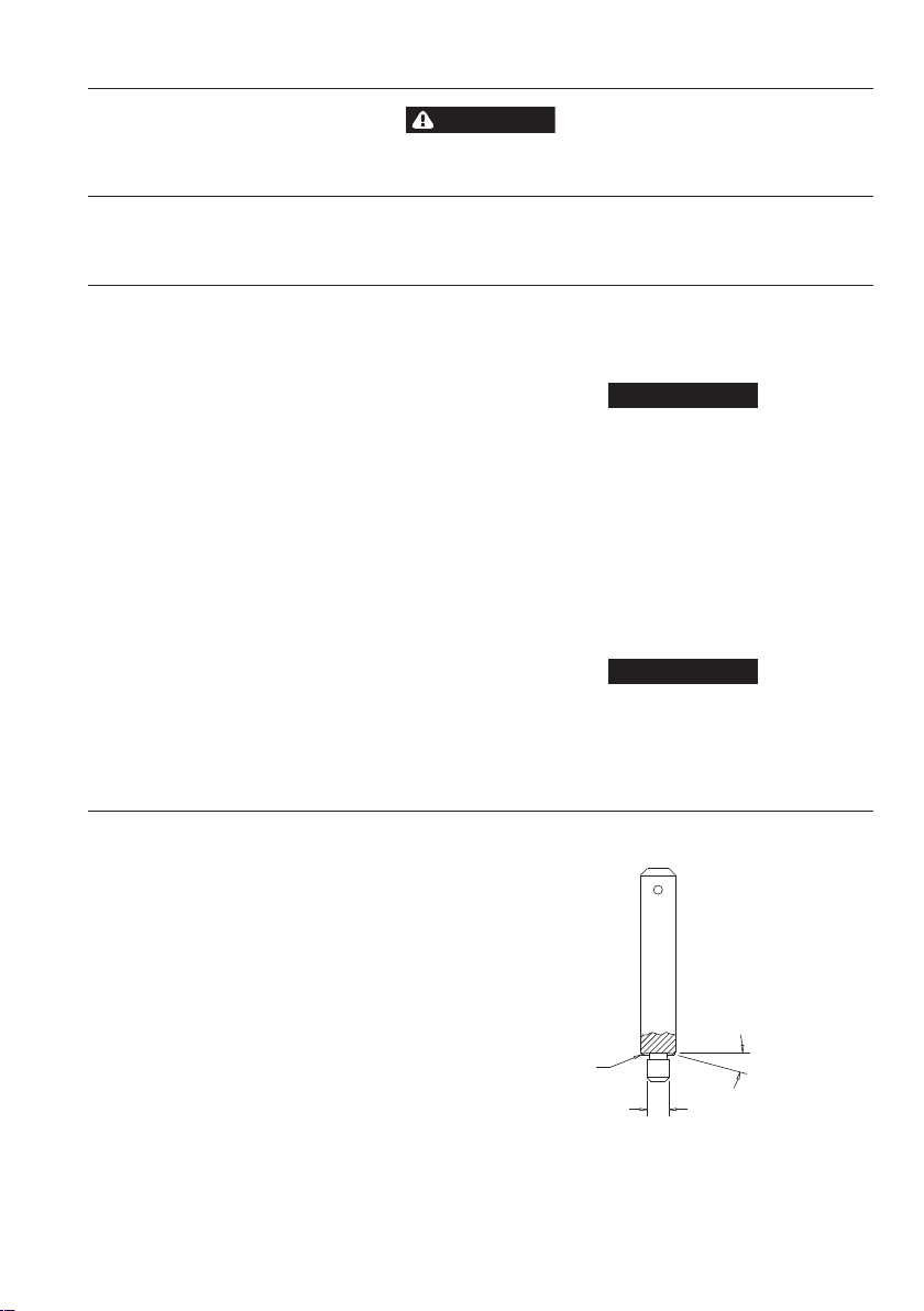
Use a bearing inserting tool similar to the one shown in
Dwg. TPD786.
Dwg. TPD-786.
04576070_ed2 5
Page 6

Assembly of the Throttle
NOTICE
NOTICE
NOTICE
1. Install Valve Stem (2) in Housing (1) so that the hole in the Valve
Stem aligns with the hole in the Housing to accept the Tip
Valve (7).
2. Install the Seat (6) in the Housing with the rounded corners on
the Seat entering the Housing first.
3. Install the Tip Valve in the Housing. Secure it with the
Valve Stem (2).
4. Install the Spring (8) and Inlet Adapter (9) in the Housing to
secure the throttle components.
5. Install the Lever (3) on the Housing and secure it with the
Roll Pin (4).
Assembly of the Motor
1. Coat O-ring (21) with O-ring lubricant and install it on the Motor
Lock Ring (22).
2. Assemble the Motor Lock Ring over the Counterbalance (24).
3. Install the Bearing (14) into the Front End Plate (20), pressing on
the Outer race of the Bearing.
4. Install the Key (23) in the key slot.
5. Install the Rotor (18) on the Counterbalance, aligning the keyway
to the Key.
6. Install the Vanes (19) in the slots in the Rotor .
7. Install the Cylinder (16) over the Rotor, aligning the roll pin in the
Cylinder with the slot in the Front End Plate.
8. Install the Bearing (14) in the Rear End Plate (15), pressing on the
Outer race of the Bearing.
9. Install the Rear End Plate with assembled Bearing on the
Counterbalance, pressing on the Inner race of the Bearing.
Align the slot in the Rear End Plate with the slot in the Cylinder.
Cold Air Channel
The Cold Air Channel and its components can be serviced as
a separate unit. It is not necessary to disassemble the tool to
perform maintenance on the Cold Air Channel.
Disassembly of the Cold Air Channel
1. Remove the Spring Clamp (33) from the Sander.
2. Slide the Supply Tube Assembly (34) out of the Housing (1).
This now leaves the Sander and Cold Air Channel free for
maintenance.
3. Slide the Hose (31) off of the Adapter Sleeve (38).
4. Unscrew the Swivel Connector (30) from the Compression Fitting
(37) and pull off the O–ring (39).
5. Remove the Retaining Ring (35).
6. Pull out the Supply Tube and Compression Fitting (37) with
Spacer (36).
10. Install the Retaining Ring (13) in the groove in the
Counterbalance with the bow in the Retaining Ring positioned as
shown in Drawing TPA1667.
11. Install the Seal (17) in the grooves in the Cylinder.
12. Install the motor assembly in the Housing aligning the Seal (19)
with the air inlet.
13. Tighten the Motor Lock Ring (22) to secure the motor assembly.
14. Lubricate the needle bearing in the counterbalance by injecting
one or two strokes of Ingersoll Rand No. 68 Grease into the
threaded end of the Spindle Assembly (25).
15. Install the Spindle Assembly on the Counterbalance, securing it
with the Retaining Ring (26).
Assembly of the Base Adapter
1. Slide the Housing Adapter (32) into the motor bore and align
holes.
2. Press the Roll Pins (41) into the Housing and
Housing Adapter (32).
3. Make sure the O-ring (39) is on the end of the cold air channel.
4. Replace the Cold Air Channel on the tool and secure it with the
Spring Clamp (33).
Installation of the Sanding Pad
1. Thread set screw into the Spindle until it locks in place.
2. Slip the spacer onto the set screw.
3. Holds the set screw in place with a 1/8” hex wrench and screw the
pad onto the set screw until it is tightened securely.
Assembly of the Cold Air Channel
1. Screw the Coupling (29) on the Hose (31).
2. Screw on the Swivel Connector (30).
3. Insert the Hose in the Coupling.
4. Install the Supply Tube (34) and Compression Fitting (37) with
Spacer (36).
5. Install the Retaining Ring (35).
6. Install the O–ring (40) and screw the Swivel Connector on the
Compression Fitting.
7. Slide the Hose over the Adapter Sleeve (38).
8. Slide the Supply Tube Assembly (34) into the sander housing.
9. Install the Spring Clamp (35) to secure the Hose.
Do not disconnect the Supply Tube and Compression Fitting.
7. Remove the Hose Connector from the Coupling (29).
8. Unscrew the Swivel Connector (30) and unscrew the Coupling
from the Hose.
6 04576070_ed2
Page 7

Troubleshooting Guide
Trouble Probable Cause Solution
Low power or low free speed Insucient air pressure Check air line pressure at the Inlet of the tool. It
Cold air head frozen Shut down the CFS200A Unit and allow the tool to
Clogged muer elements Disassemble the tool and agitate the bare Motor
Plugged Inlet Screen Clean the Inlet Screen in a clean, suitable, cleaning
Worn or broken Vanes I nstall a complete set of new Vanes.
Worn or broken Motor Housing Replace the Motor Housing.
Internal air leakage in the Motor Housing
indicated by high air consumption/
low speed.
Grit buildup under the Throttle Lever restricting
full Throttle Valve Plunger movement.
Bent stem on Throttle Valve Replace the Throttle Valve
Excessive runout Bent Arbor Replace the Arbor.
Scoring of Eng Plate Worn Front End Plate. Install a new Front End Plate.
Worn Front Rotor Bearing Install a new Front Rotor Bearing.
Leaky Throttle Valve Dir t accumulation on Throttle Valve or Throttle
Front Rotor Bearing runs hot Incorrect Front Rotor Bearing installation orienta-
Slow tool idle Bent or leaky Throttle Valve Replace the Throttle Valve.
Rough operation/vibration Improper lubrication or dirt buildup Disassemble the tool and clean in a clean,
Excessive ice build–up on cold
air head
Valve Seat
Worn Throttle Valve or Throttle Valve Seat Replace the Throttle Valve and/or Throttle Valve
Excessive dirt build–up beneath the Throttle Lever Clean out the slot area.
Bent Throttle Valve Plunger Replace the Plunger.
tion
Worn or broken Rear Rotor Bearing or Front Rotor
Bearing
Air pressure is set too high in either the idle or
operating mode
must be 90 psig (6.2 bar/620 kPa).
warm for about 1/2 hour.
Housing and Flange in a clean, suitable cleaning
solution. If the elements cannot be cleaned,
replace the Motor Housing and/or the Flange.
solution or replace the Screen.
Replace the Motor Housing.
Remove the Throttle Lever and clean the groove
in the Motor Housing.
Disassemble, inspect and clean parts.
Seat.
Remove the Bearing and install it correctly or
replace the Bearing.
suitable, cleaning solution. Assemble the tool
and inject 3 cc of the recommended oil into the
Inlet and run the Buer long enough to coat the
internal parts with the oil.
Replace the worn or broken Bearings.
Shut CFS200A Unit down and allow it to warm for
approximately 1/2 hour.
04576070_ed2 7
Page 8

www.irtools.com
© 2009 Ingersoll Rand Company
 Loading...