

Ingersoll-Rand QX Series User Manual
QX Series Display
User Manual
48619852
Edition 1
July 2012
EN
User Manual
ES
Manual de usuario
FR
Manuel d’utilisation
IT
Manuale per l’uente
DE
Benutzerhandbuch
NL
Gebruikershandleiding
DA
Brugervejledning
SV
Bruksanvisning
NO
Brukerhåndbok
FI
Käyttöopas
PT
Manual do Utilizador
EL
Εγχειρίδιο Χρήστη
SL
Uporabniški priročnik
SK
Používateľská príručka
CS
Návod pro uživatele
ET
Kasutusjuhend
HU
Felhasználói kézikönyv
LT
Naudotojo vadovas
LV
Lietotāja rokasgrāmata
PL
Podręcznik użytkownika
BG
Ръководство на потребителя
RO
Manual de utilizare
RU
Руководство пользователя
ZH
用户手册
JA
ユーザー マニュアル
KO
사용자 설명서
Save These Instructions

EN
Purpose of the document:
This document provides details about dierent menu screens, their description and how to edit those screens in display
module, required for the operation of QX Series Hand Tool.
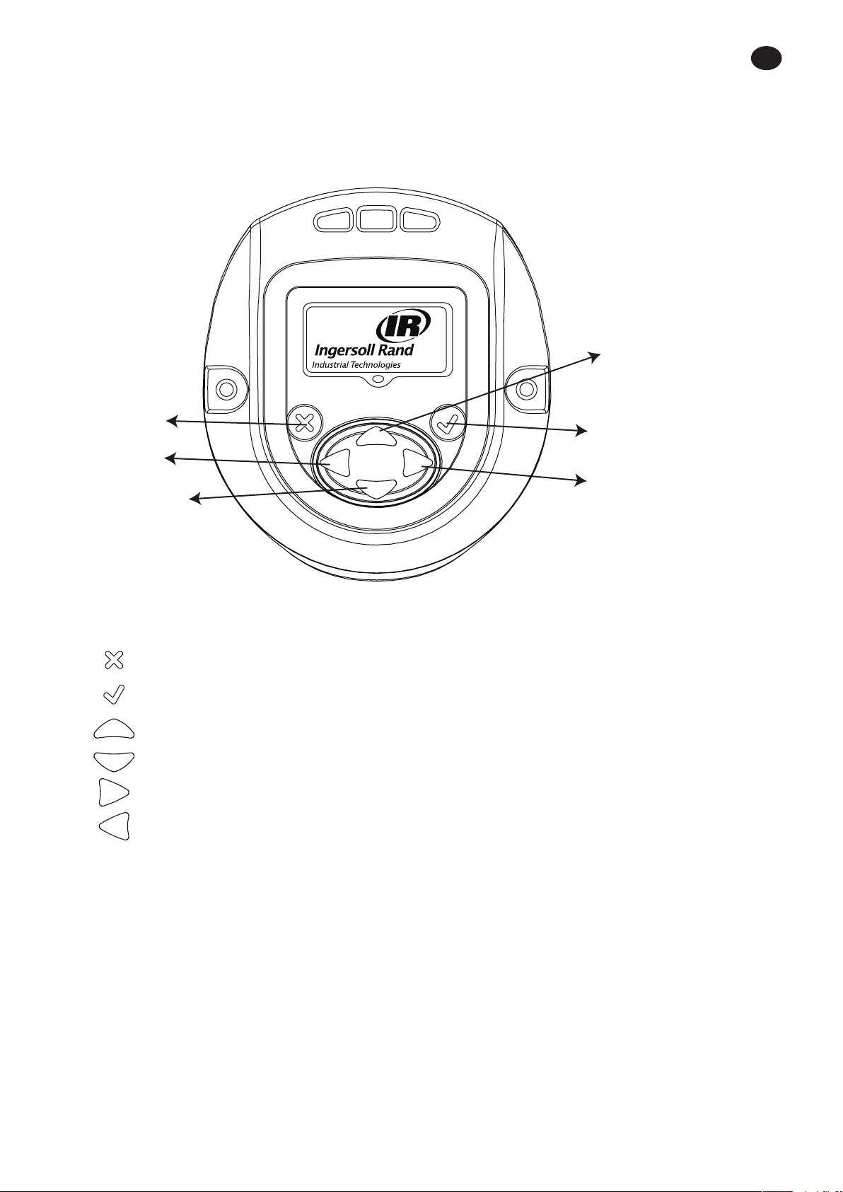
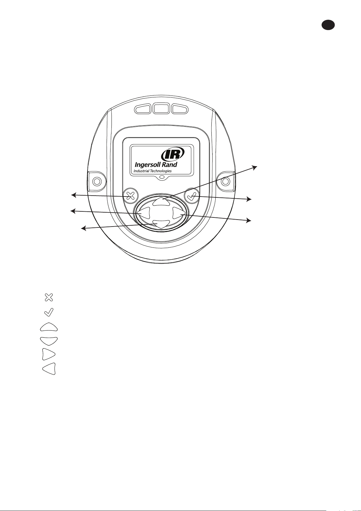
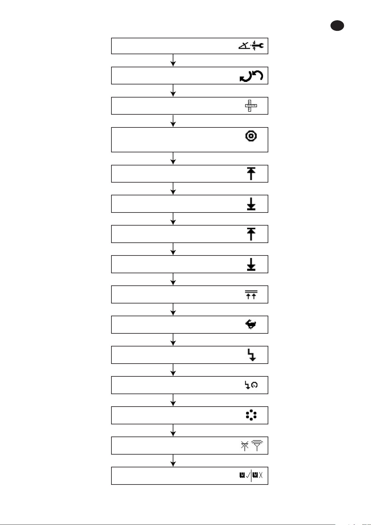
The image Below shows the display of QX Series display module with descriptions of the programming keys.
UP
ESCAPE
LEFT
DOWN
Symbol Function
Escape / Exit
Enter / Edit
UP
DOWN
RIGHT
LEFT
ENTER
RIGHT
48619852_ed1 EN-1
EN
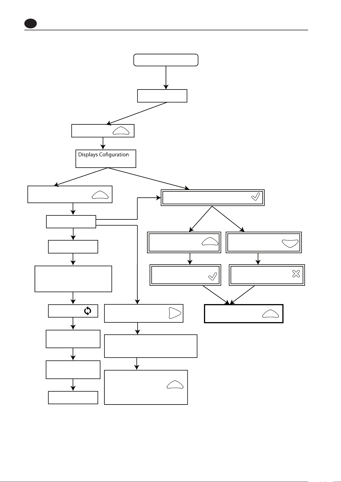
Power up QX Series tool
RUN SCREEN
Press “UP” key
Number being used
Always Press “UP” key to
go to next screen
Press “ENTER” to enter “EDIT” mode
Password screen
Current fault
Status screen with shunt
cal, wireless strength and
battery level.
Cycle Count
Target Angle, Low
and High screen
Target Torque Low
and High screen
RUN SCREEN
Press “UP” key to
increment the value
Press “DOWN” key to
decrement the value
Press “ENTER” to select
the changed values.
Press “ESC” to undo and
keep the old values.
After display is unlocked
Press “RIGHT” Key
Press “UP” key to go to
next screen
Save or Ignore changes. If not on
Save screen, use the up or down
key to scroll to the Save screen.
Press “UP” key to scroll
on one by one to get
below editable screens
in seriesscreen.
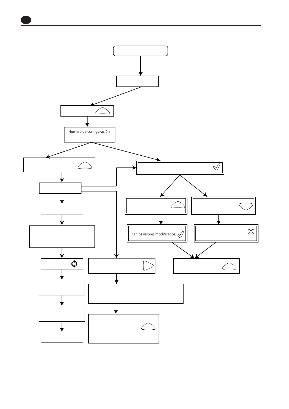
1. Overview of dierent Menu screens
EN-2 48619852_ed1
EN
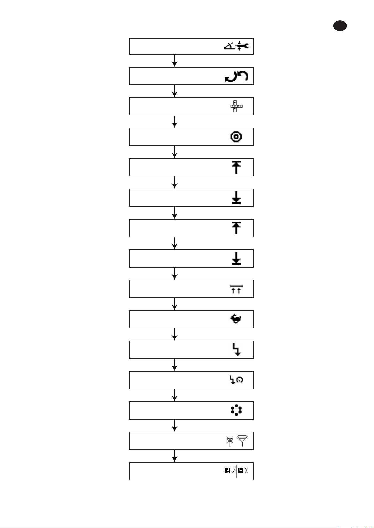
Strategy – Angle or Torque
Direction – Clock wise or anti
clockwise
Unit of Torque
Target Angle (Angle strategy) OR
Target torque (Torque strategy)
Torque High
Torque Low
Angle High
Angle Low
Torque threshold
Free Speed
Shift down torque
Shiftdown Speed
Gang count
Enable / disable RF module
Save / ignore the changes
settings
48619852_ed1 EN-3

EN
2. Description of the Display screen in detail
There are three sections in the QX Series display screen, one “PRIMARY” on the top and two “SECONDARY” which are on
left and right bottom of the display.
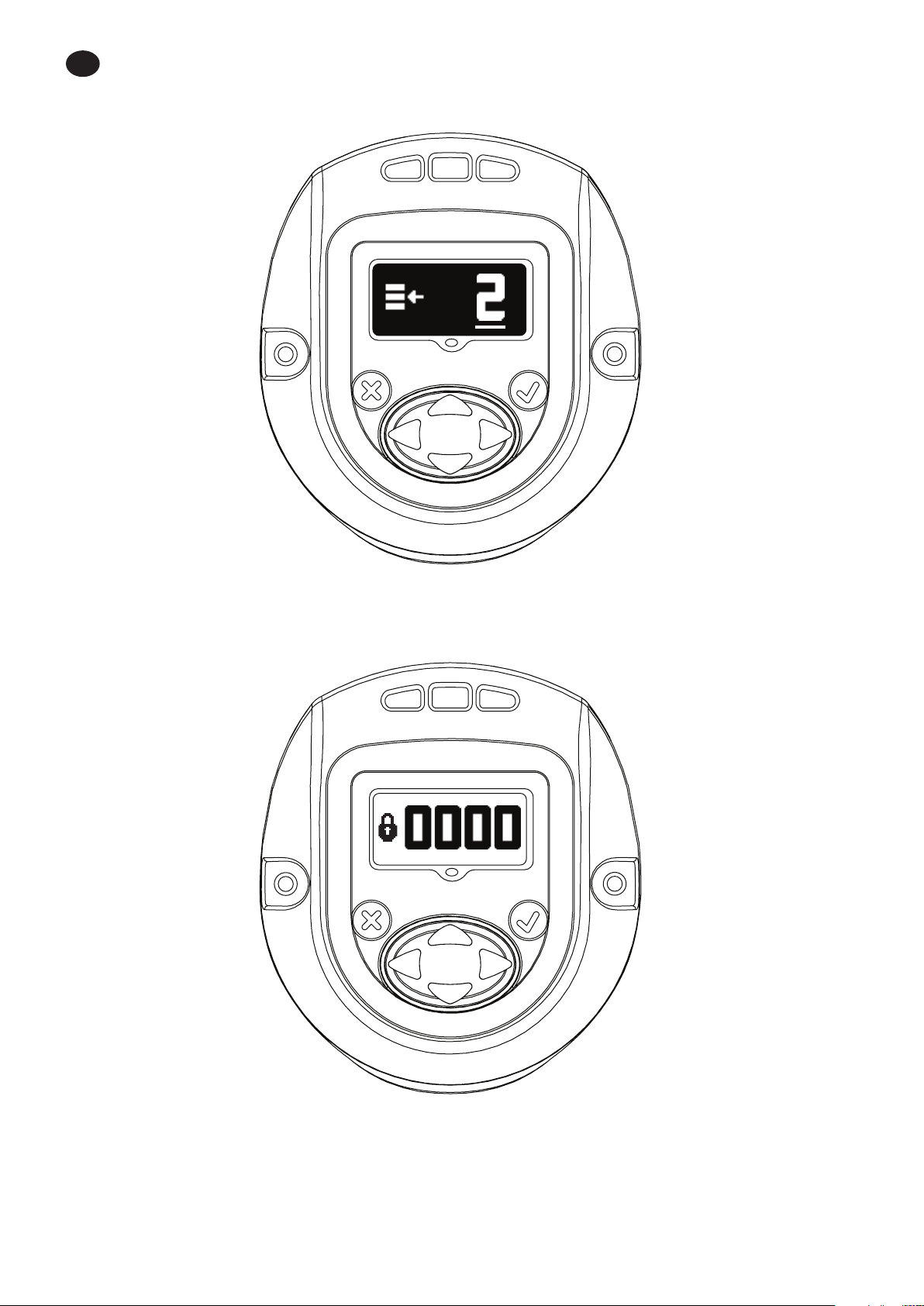
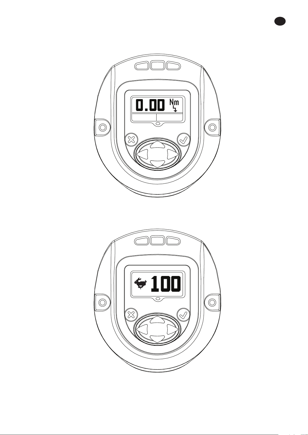
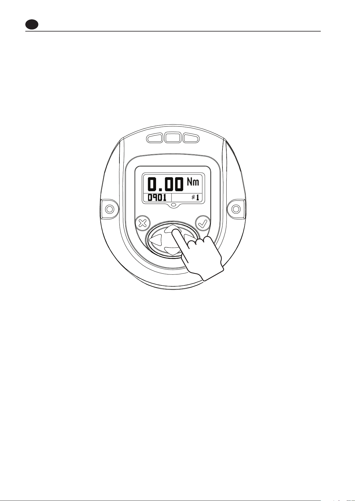
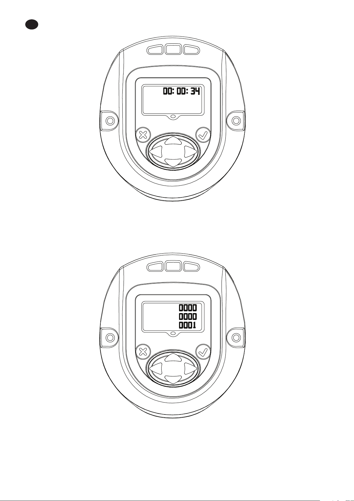
2.1. Run Screen
Pressing “ENTER” key after switching on the display will show this image.
PRIMARY Section - shows latest peak torque (for a torque strategy) or the latest peak angle (for an angle strategy), with
units.
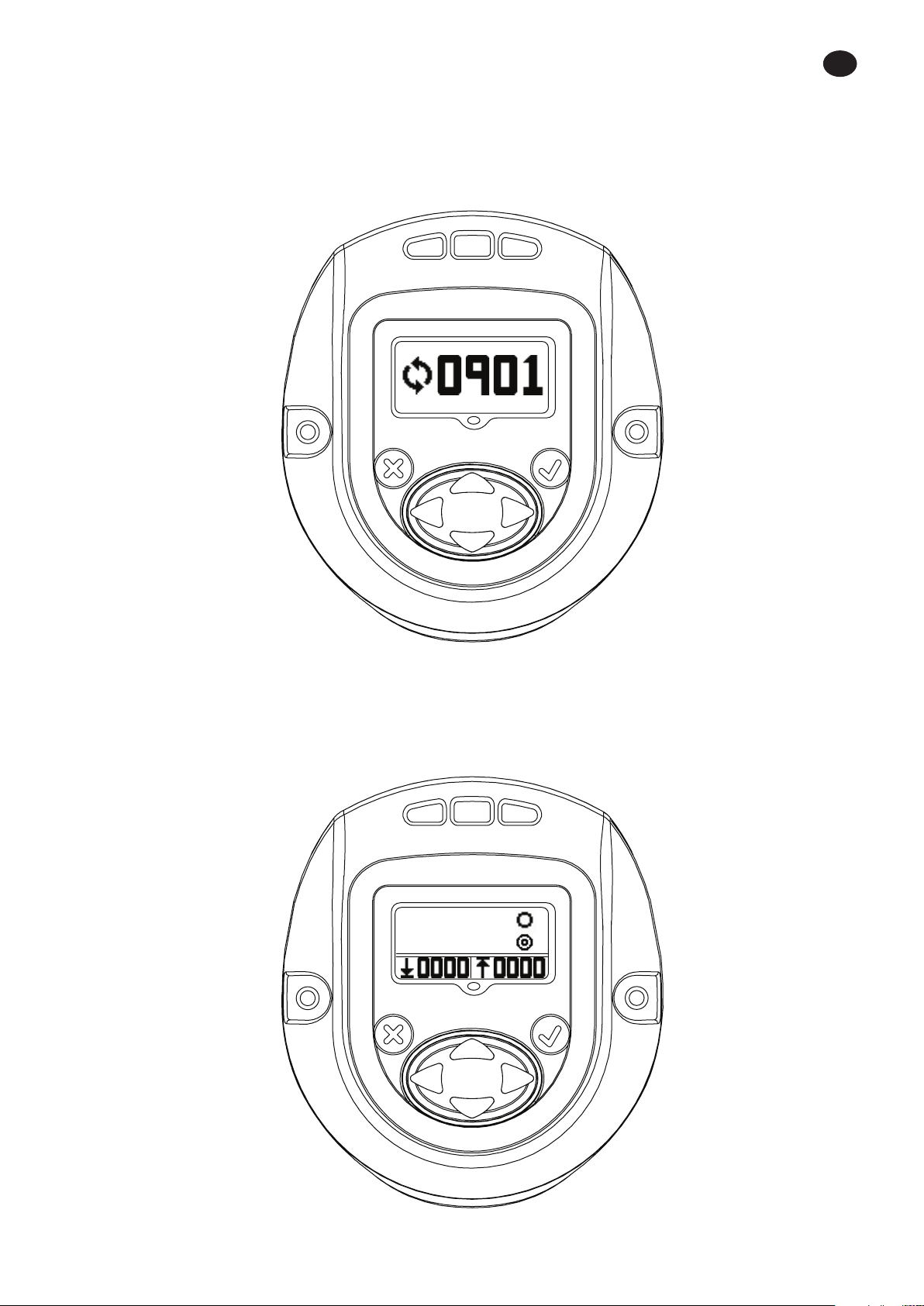
The SECONDARY LEFT - shows the cycle count or gang count, if gang count is programmed.
The SECONDARY RIGHT - shows the active conguration number.
EN-4 48619852_ed1

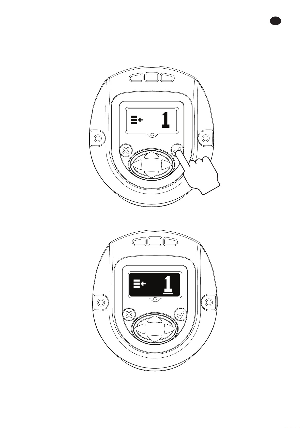
2.2. Conguration
Pressing “UP” will advance to next screen.
Screen shows CONFIGURATION setting used in the tool.
NOTE: Only Conguration 1 can be programmed through the display module.
EN
Pressing “ENTER” will enable the “EDIT MODE” (This procedure to enter “EDIT MODE” is same for all settings update).
48619852_ed1 EN-5
EN
“UP” or “DOWN” key can be used to update the conguration. Pressing “ENTER” again will select the modied
conguration.
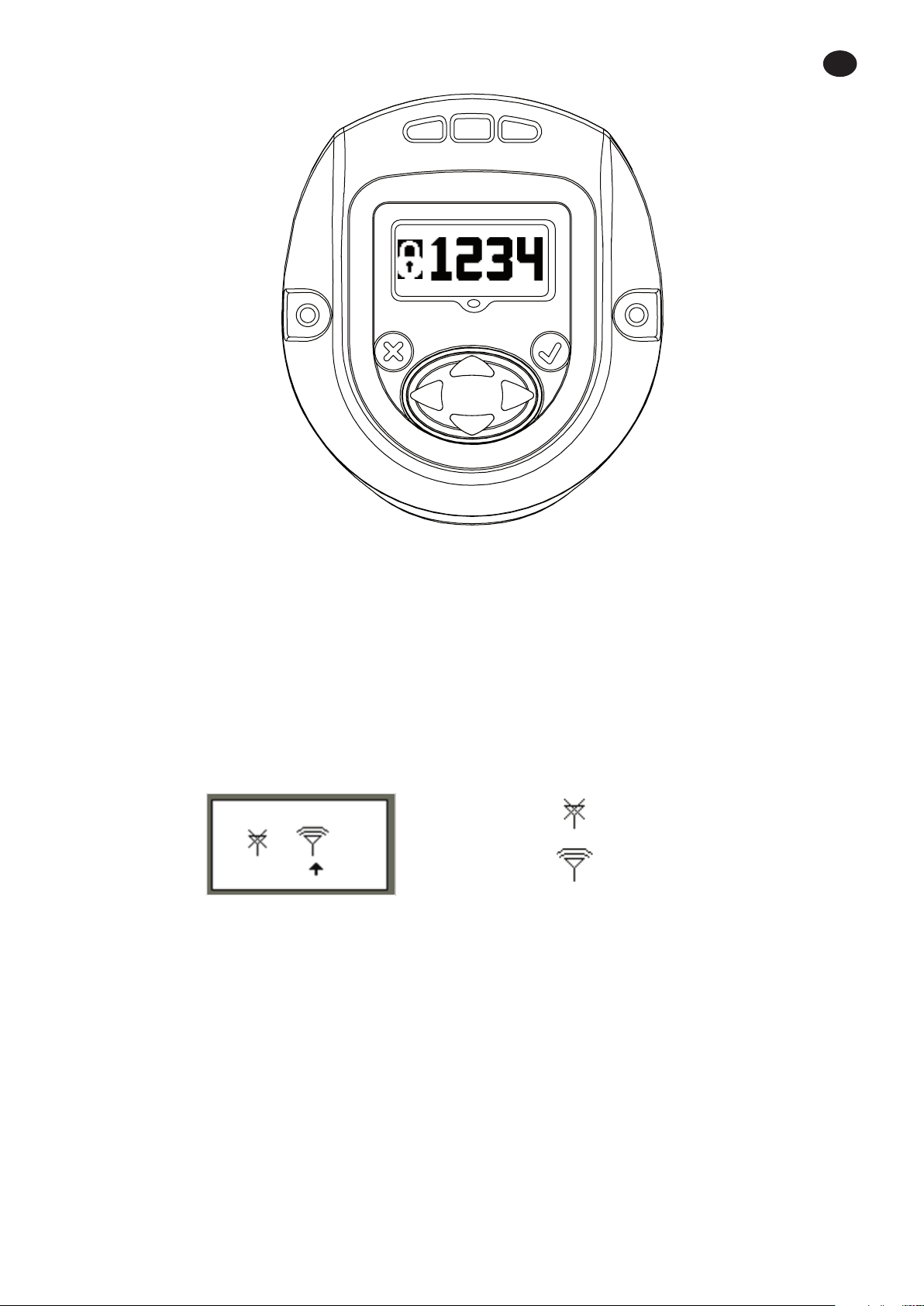
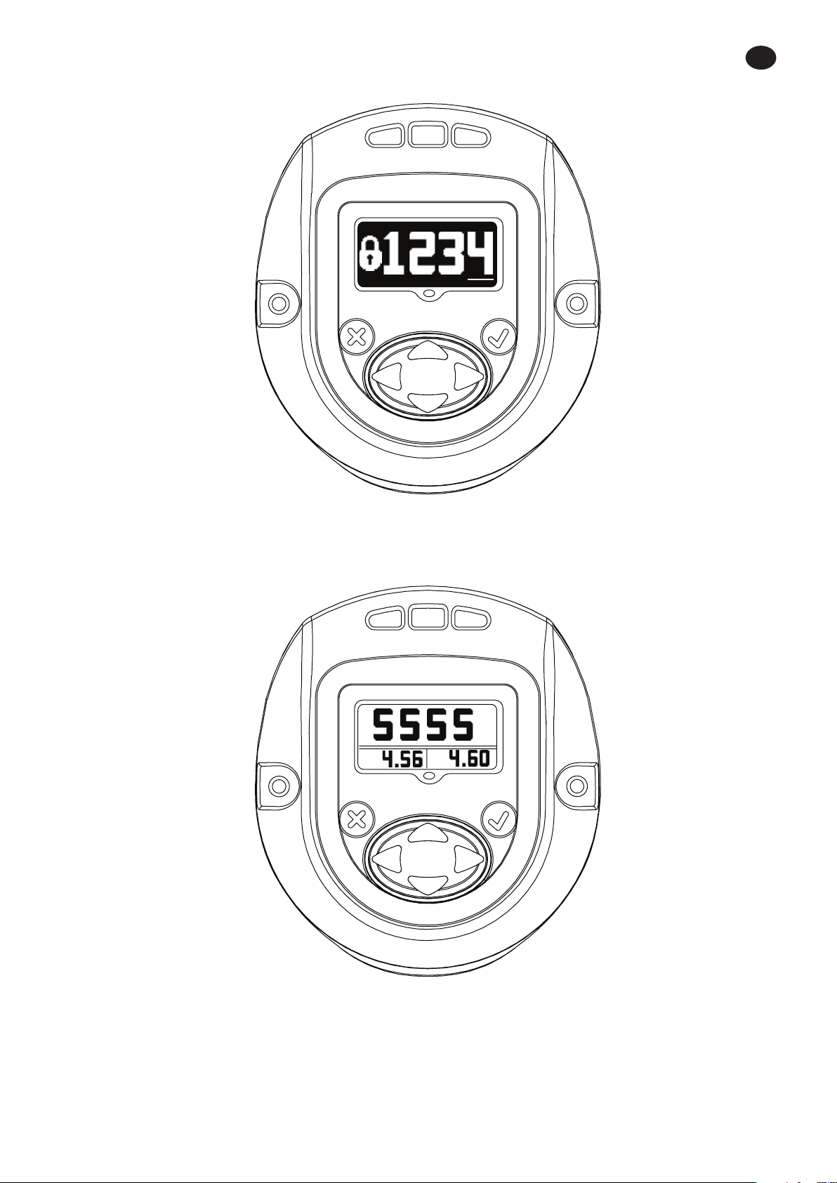
2.3. Password
The password screen shows whether the display is locked or unlocked. If the display is locked the parameters of the QX
Series Hand tool cannot be edited.
EN-6 48619852_ed1

Password can be changed by entering into “EDIT MODE” and using “UP” or “DOWN” key.
EN
If “1234” is entered on the Password screen, the user may use the left arrow to go to the Tool ID and software version
page.
The Primary Display is the “Tool Location ID”.
Lower Secondary Right is the “Display Firmware” Version.
Lower Secondary Left is the “Motor Controller Firmware” Version.
48619852_ed1 EN-7
EN
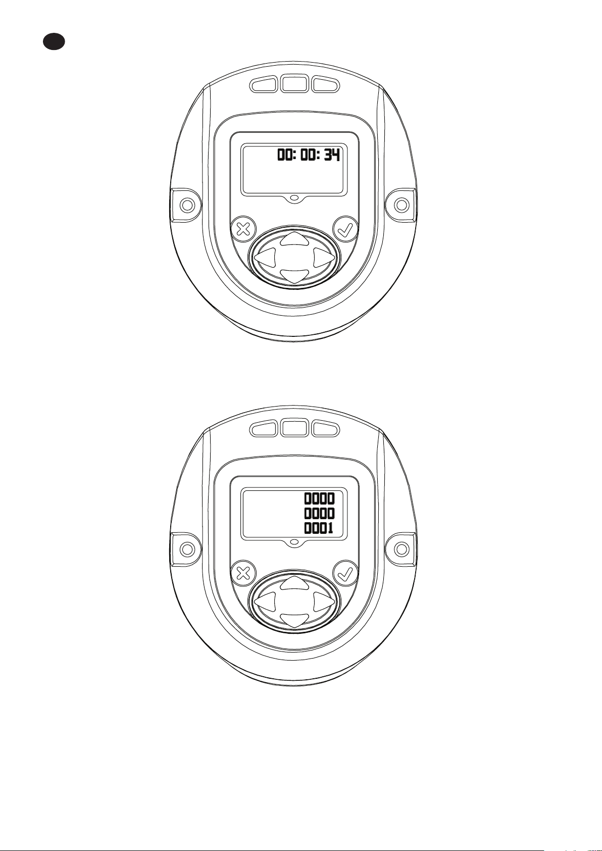
Displays Tool time in HH:MM:SS format. Press the Down key to display the tool time in HH:MM:SS format.
Remaining screens are for internal use only to view log location. Press the Down key to display a screen for internal use
only to view log location. Press the Down key again to display a second log screen.
Press the Down key again to return to the Tool ID page. Pressing the right arrow from this page exits back to the
password display.
EN-8 48619852_ed1
EN
Press ‘ENTER’ to enter the ‘EDIT’ mode. Enter the appropriate password to unlock the tool. Press ‘ENTER’ to exit the ‘EDIT’
mode.
2.3.1. Updating parameters of the QX Series tool
After display is unlocked with a valid password, Pressing “RIGHT” key will advance to following settings that can be
modied as required.
The settings can be modied by entering “EDIT MODE” and using “UP” or “DOWN” key or “RIGHT” or “LEFT” key as
required.
2.3.2. Radio Enable/Disable
This screen allows the user to enable or disable the radio module. The selection on the left disables the radio module
and the selection on the right enables the radio module.
RADIO DISABLED
RADIO ENABLED
48619852_ed1 EN-9
EN
2.3.3. Gang count
The below screen shows the gang count number of bolts to be fastened per Group, Gang, or Set for Conguration 1.
This can be modied by entering “EDIT MODE”.
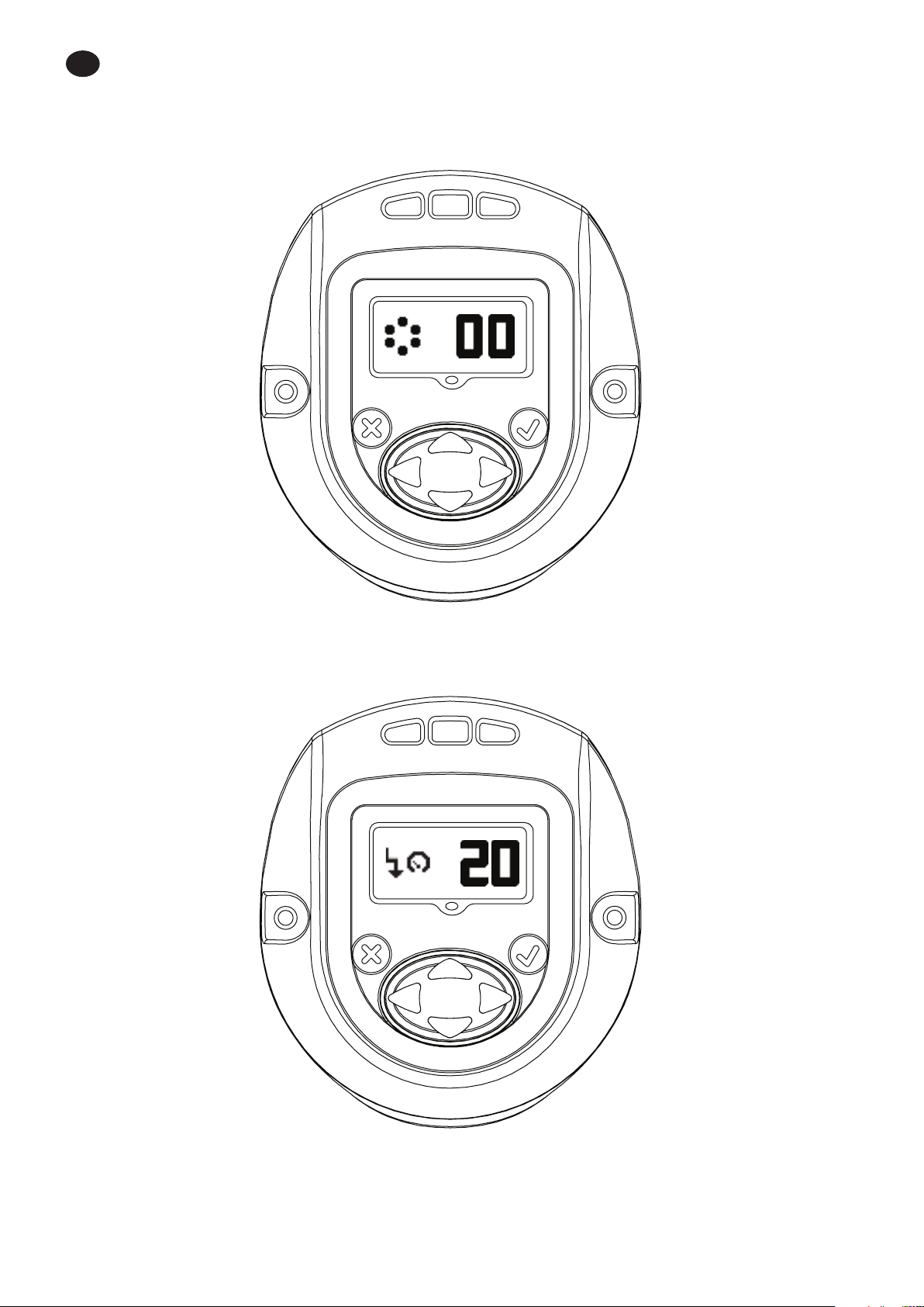
2.3.4. Shiftdown Speed
This screen indicates shiftdown speed of the QX Series tool. Shiftdown speed can be edited by entering “EDIT MODE”
and updating using UP and DOWN arrow. Programmed speed is a percentage of tool maximum speed.
EN-10 48619852_ed1
2.3.5. Shiftdown Point Cong
This screen indicates “Torque Threshold for shiftdown point”. This can be changed by entering “EDIT MODE” and
updating using “UP” or “DOWN” key.
EN
2.3.6. Free Speed
The below screen indicates free speed of the QX Series tool. The value can be edited by entering “EDIT” mode and using
“UP” and “DOWN” arrow. Programmed speed is a percentage of tool maximum speed.
48619852_ed1 EN-11
EN
2.3.7. Torque Threshold
The Torque at which reading of the angle will be started. The value can be edited by entering “EDIT” mode and using
“UP” and “DOWN” arrow.
2.3.8. Angle
Angle “LOW” Display
Angle “LOW” can be modied in this mode by
entering “EDIT” mode and using “UP or “DOWN” key.
Angle “HIGH” Display
Angle “HIGH” can be modied in this mode by
entering “EDIT” mode and using “UP or “DOWN” key.
EN-12 48619852_ed1

2.3.9. Torque
EN
Torque “LOW” Display
Torque “LOW” can be modied in this mode by
entering “EDIT” mode and using “UP or “DOWN” key.
Torque “HIGH” Display
Torque “HIGH” can be modied in this mode by
entering “EDIT” mode and using “UP or “DOWN” key.
Torque “TARGET” Display.
Torque “TARGET” can be modied in this mode by entering “EDIT” mode and using “UP or “DOWN” key.
48619852_ed1 EN-13
EN
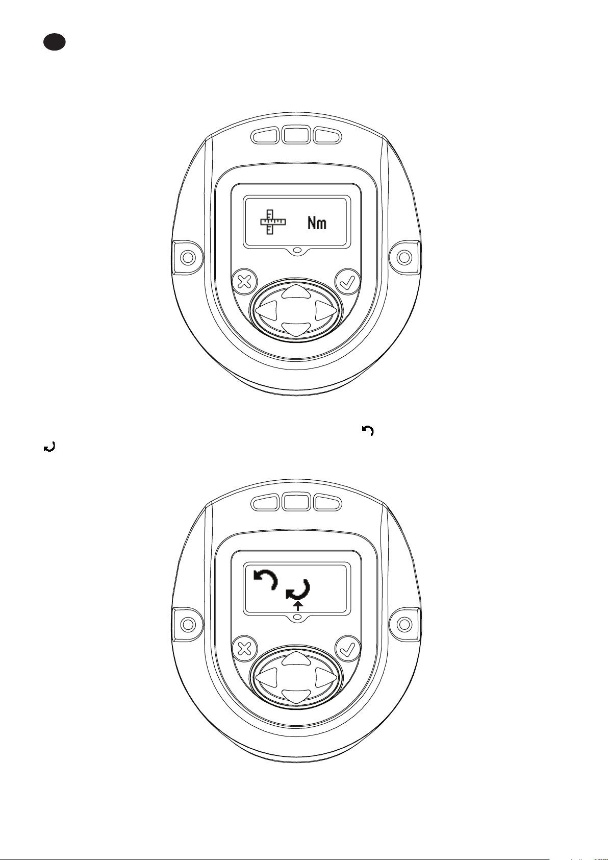
2.3.10. Unit of the Torque
Indicates unit of the Torque displayed in Conguration 1.
This can be changed by entering “EDIT MODE” and updating using “UP” or “DOWN” key.
2.3.11. Direction of Rotation
Image shows direction of rotation in which the QX Series hand tool rotates. Indicates counter clock wise rotation.
Indicates clock wise rotation
This can be changed by entering “EDIT MODE” Key and updating using “RIGHT” or “LEFT” key.
EN-14 48619852_ed1
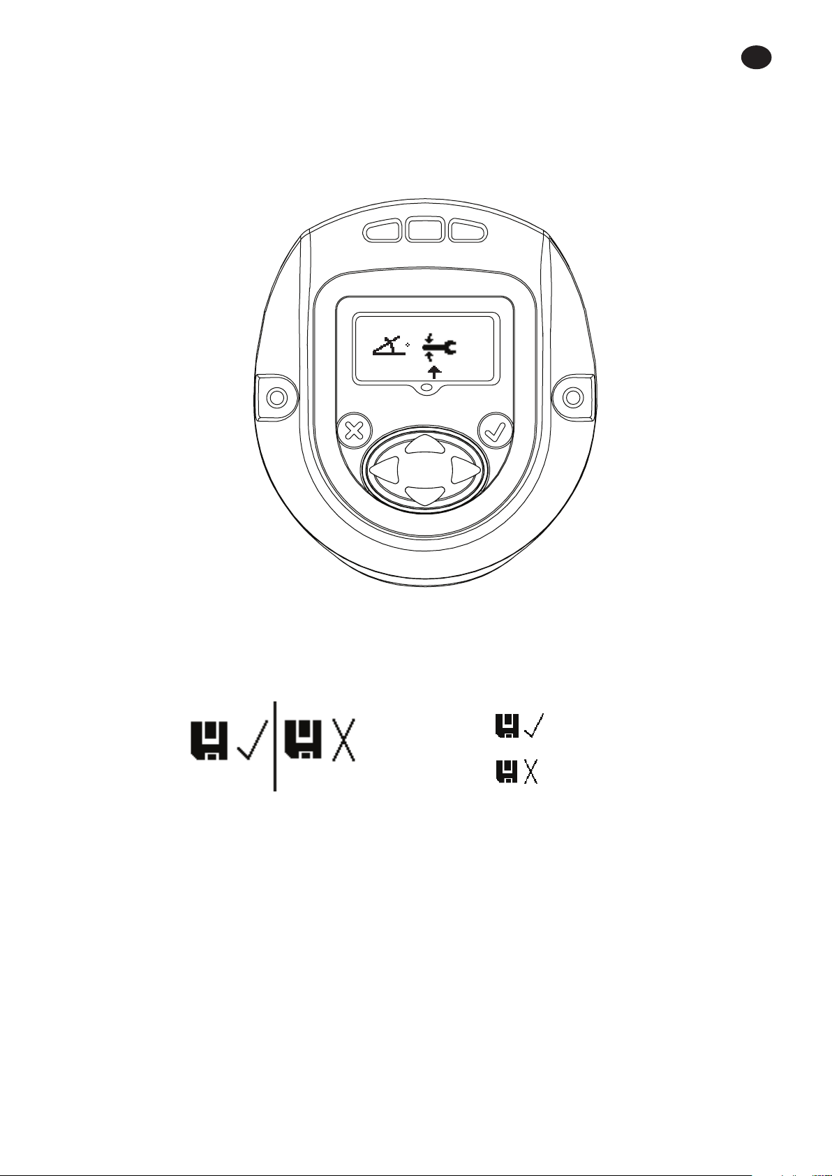
2.3.12. Strategy
This screen indicates conguration strategy being used.
Left – Angle, Right – Torque.
The pointing arrow indicates the present conguration being used.
This can be changed by entering “EDIT MODE” and using “RIGHT” or “LEFT” key.
EN
2.3.13. Save / Ignore Settings
After all the required changes are completed, Press enter to highlight the save settings box on the left. Press the right or
left arrow key to select cancel on the right. Pressing enter a second time causes the tool to leave edit mode.
SAVE SETTINGS
CANCEL SETTINGS
48619852_ed1 EN-15
EN
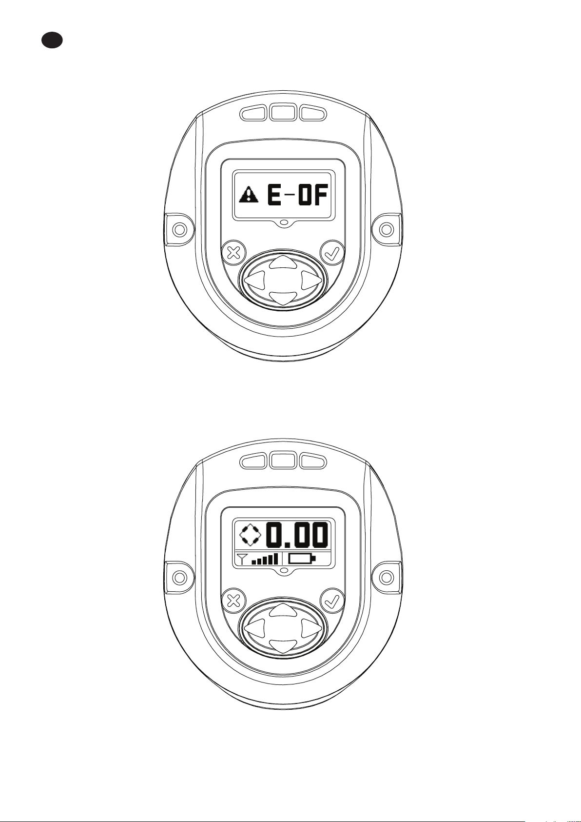
2.4. Warning Screen
This is the next screen obtained after pressing “UP” key when QX Series displays the Password screen.
2.5. Shunt Calibration, RF Signal Strength and Battery level
This is the next screen obtained after pressing “UP” key when QX Series displays password screen.
Primary display indicates Shunt Calibration Value.
Secondary display on left indicates RF signal strength and the one on the right indicates Battery Level.
EN-16 48619852_ed1
EN
2.6. Cycle count
This value shows number of cycles run by the QX Series tool, Since the last time it was changed.
With the tool unlocked, press ‘ENTER” key to edit this screen. Press either the ‘UP’ or ‘DOWN’ key to clear the cycle count.
For this change to be retained a cycle must be run before removing power to the tool. Otherwise, the old cycle count is
restored.
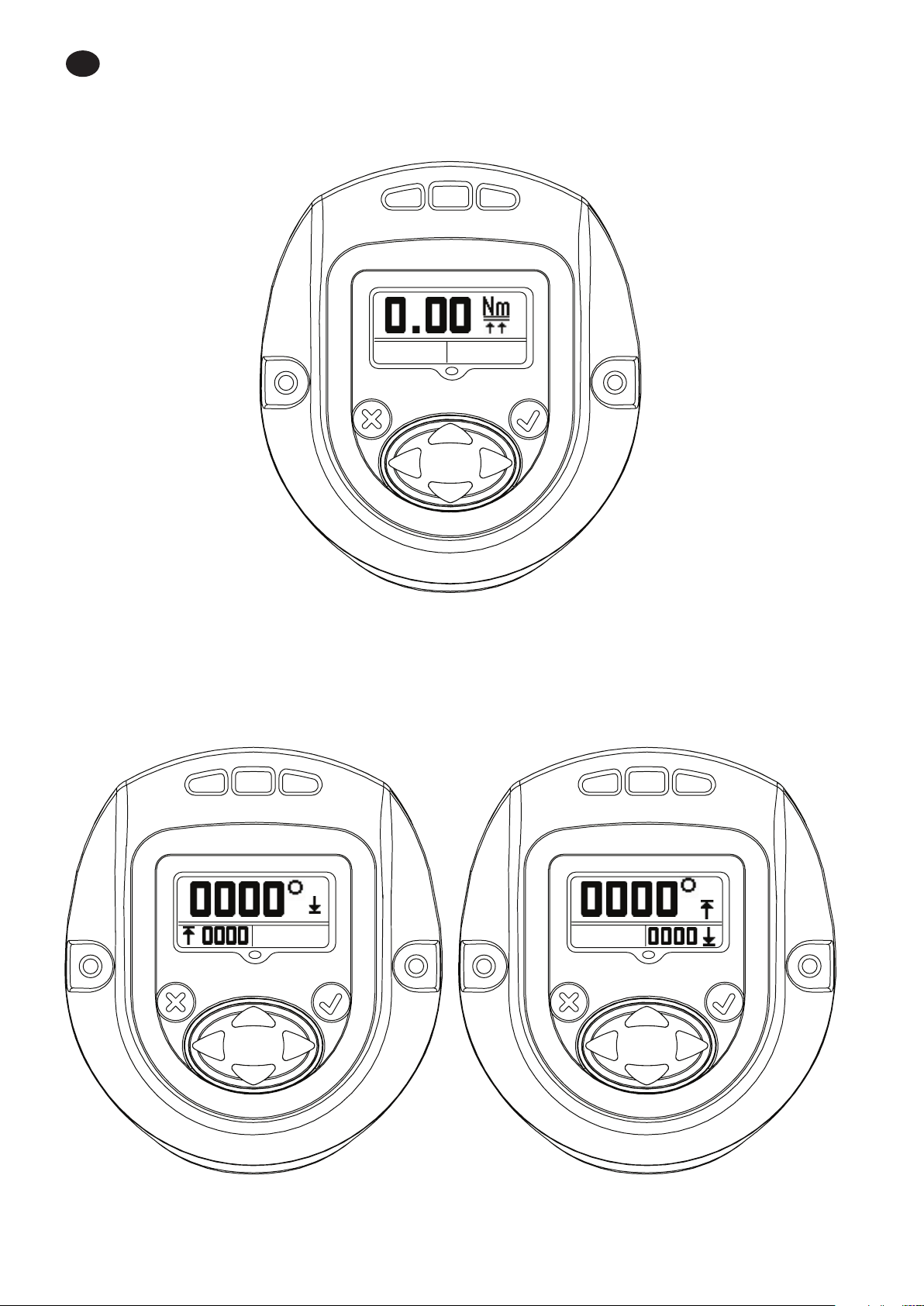
2.7. Angle
Primary display – Target Angle.
Secondary Display on left - Angle low.
Secondary Display on right - Angle High.
48619852_ed1 EN-17

EN
2.8. Torque
Primary Display -Target Torque.
Secondary display on left - Torque low.
Secondary display on Right - Torque high.
Pressing “UP” advances back to “RUN SCREEN”, the rst display screen.
EN-18 48619852_ed1

Appendix 1 : Status LED Denitions
There are four LEDs on the display module. 3 on the top and 1 below the display screen.
The Status LEDs shall be used as follows:
Red -- The last tightening cycle exceeded its high limit.
Yellow -- The last tightening cycle ended below its low limit.
Green -- The last tightening cycle ended between its high and low limits.
Blue -- The tool has an active fault condition.
Appendix 2 : Tool Fault codes
The tool shall report the following fault codes for the listed conditions:
F-01 Tool Disabled (by external control)
F-02 Rapid Trigger pull – trigger was pulled before conguration delay was complete
1-FF USB enumeration fault
A-10 Motor controller communication timeout
A-55 A display software version update was detected
B-01 Failure to update Motor Controller Software
B-85 RF ACK Timeout (we did not get a serial ACK messages from the transceiver)
B-E1 RF Transmit NAK–“Channel Access Failure”
B-E5 RF Transmit NAK–“Frame Too Long”
B-E9 RF Transmit NAK–“No ACK Received”
C-01 Conguration ID value is 0 or greater than 8
C-02 Number of conguration steps is greater than 8
C-03 Current Step ID is greater than the current number of steps
C-04 Total Gang is greater than 8
C-05 Current Gang count is greater than Total Gang
C-06 Current Torque High Limit is greater than the Tool’s maximum Torque value (Tool’s max torque value
is congured in the Factory Set Points) OR Current Torque High Limit is less than 0
C-07 Current Torque Low Limit is greater than the Tool’s maximum Torque value OR Current Torque Low
Limit is less than
C-08 Current Torque High Limit is less than Current Torque Low Limit
C-09 Current Torque Low Limit is greater than Current Torque High Limit (Fault code to be removed)
C-0A Current Angle High Limit is greater than the Tool’s maximum Angle value (to be set to 9999)
C-0B Current Angle Low Limit is greater than the Tool’s maximum Angle value (to be set to 9999)
C-0C Current Angle High Limit is less than Current Angle Low Limit
C-0D Current Angle Low Limit is greater than Current Angle High Limit (Fault code to be removed)
C-0E
C-0F
C-10 Tool conguration step is not set for either Angle or Torque
C-11
C-12 Current Free Speed is greater than maximum motor speed
C-13 Current Shiftdown Speed is greater than maximum motor speed
C-14 Current display unit value is unsupported
C-15 Torque Threshold exceeds target (with torque target) or max torque (with Target Angle)
C-55 Invalid Conguration selection
E-00 Battery Fault
E-01 Invalid Hall State
Tool conguration step is a Target torque and the target value is outside the torque high and low limits
Tool conguration step is an Target Angle and the target value is outside the angle high and low limits
Current Threshold value is greater than the maximum tool torque OR Current Threshold value is less than 0
EN
48619852_ed1 EN-19

EN
E-02 I2T Fault
E-03 Motor Stall
E-04 Over Current
E-05 Over Temperature
E-06 Current O set Fault
E-07 Shunt Calibration Fault
E-08 Torque Oset Fault
E-09 Transducer Fault
E-0A Step Execution Timeout
E-0B Conguration Execution Timeout
E-0C Over Torque Limit
E-0D Over Angle Limit
E-0E Current Plausibility High
E-0F Under Torque
E-10 Under Angle
E-11 Current Plausibility Low
E-12 Early trigger Release
E-13 Motor Controller Watch dog Reset
E-14 Brake Timeout
E-18 Missed Run Steps (Prevailing Torque conguration did not complete)
E-1B Battery Cell Fault (detected by Motor Controller)
E-1C Low Battery Fault (detected by Motor Controller)
E-1D Critical Battery Fault (detected by Motor Controller)
E-1E Motor Controller is shutting down
E-1F Wakeup Code received (but not expected)
E-81 The conguration ID in the Motor controller’s EOR did not match the currently selected conguration
2-<Alarm ID> PM Alarm Time Fault for corresponding Alarm ID normally congured by the user
3-<Alarm ID> PM Alarm Cycle Fault for corresponding Alarm ID normally congured by the user
C-16 Number of conguration steps is set to 0
Parts and Maintenance
Original instructions are in English. Other languages are a translation of the original instructions.
Tool repair and maintenance should only be carried out by an authorized Service Center.
Refer all communications to the nearest Ingersoll Rand Oce or Distributor.
EN-20 48619852_ed1
ES
Finalidad del documento:
Este documento proporciona información detallada sobre las diferentes pantallas de los menús, su descripción y la
edición de dichas pantallas en el módulo de la pantalla de visualización, necesario para utilizar la herramienta manual
de la serie QX.
La imagen incluida a continuación muestra el módulo de la pantalla de visualización de la serie QX con descripciones
de las teclas de programación.
ARRIBA
ESCAPE
IZQUIERDA
ABAJO
Símbolo Función
Escape / salida
ENTRAR / EDICIÓN
ARRIBA
ABAJO
DERECHA
IZQUIERDA
ENTRAR
DERECHA
48619852_ed1 ES-1
ES
Encendido de la herramienta de
la serie QX
PANTALLA DE
EJECUCIÓN
Pulse la tecla
“ARRIBA”
de las pantallas en uso
Pulse siempre la tecla
“ARRIBA” para pasar a la
siguiente pantalla
Pulse “ENTRAR” para acceder al modo de
“EDICIÓN”
Pantalla de la
contraseña
Fallo de corriente
Pantalla de estado con la
calibración por derivación, la
intensidad inalámbrica y el
nivel de la batería
Recuento de
ciclo
Pantalla de ángulo
objetivo inferior y
superior
Pantalla de par de
torsión objetivo inferior y
superior
PANTALLA DE
EJECUCIÓN
Pulse la tecla “ARRIBA”
para incrementar el valor
Pulse la tecla “ABAJO”
para reducir el valor
Pulse “ENTRAR” para seleccio-
Pulse “ESC” para deshacer
el cambio y conservar los
valores antiguos.
Una vez desbloqueada
la pantalla, pulse la tecla
“DERECHA”
Pulse la tecla “ARRIBA” para
pasar a la siguiente pantalla
Guarde o ignore los cambios. Si no se encuentra en la
pantalla de guardado, utilice la tecla arriba o abajo para
desplazarse hasta dicha pantalla.
Pulse la tecla “ARRIBA” para
desplazarse por las pantallas
una a una y obtener las
pantallas editables siguientes
en serie
1. Descripción general de las pantallas de los distintos menús
ES-2 48619852_ed1
ES
Estrategia: ángulo o par de torsión
Dirección: en el sentido de las aguja del reloj
o en sentido contrario a las agujas del reloj
Unidad del par de torsión
Ángulo objetivo (estrategia de ángulo) O
par de torsión objetivo (estrategia de par de
torsión)
Par de torsión superior
Par de torsión inferior
Ángulo superior
Ángulo inferior
Umbral del par de torsión
Velocidad libre
Par de torsión de desaceleración
Velocidad de desaceleración
Recuento de grupo
Habilitar/deshabilitar el módulo de
radiofrecuencia
Guardar/ignorar la conguración de los
cambios
48619852_ed1 ES-3
ES
2. Descripción de la pantalla de visualización en detalle
Existen tres secciones en la pantalla de visualización de la serie QX, una “PRINCIPAL” situada en la parte superior y dos
“SECUNDARIAS” situadas a la izquierda y a la derecha de la parte inferior de la pantalla.
2.1. Pantalla de ejecución
Al pulsar la tecla “ENTRAR” tras encender la pantalla, se mostrará esta imagen.
Sección PRINCIPAL: muestra el último par de torsión máximo (para una estrategia de par de torsión) o el último ángulo
máximo (para una estrategia de ángulo), con sus unidades.
Sección SECUNDARIA IZQUIERDA: muestra el recuento de ciclo o el recuento de grupo, si se ha programado este último.
Sección SECUNDARIA DERECHA: muestra el número de conguración activo.
ES-4 48619852_ed1
2.2. Conguración
Al pulsar la tecla “ARRIBA”, se pasará a la siguiente pantalla.
La pantalla muestra el ajuste de CONFIGURACIÓN utilizado en la herramienta.
NOTA: solo puede programarse la Conguración 1 a través del módulo de la pantalla de visualización.
ES
Al pulsar la tecla “ENTRAR”, se habilitará el “MODO DE EDICIÓN” (este procedimiento de acceso al “MODO DE EDICIÓN” es
el mismo para la actualización de todos los parámetros de conguración)
48619852_ed1 ES-5

ES
Las teclas “ARRIBA” o “ABAJO” pueden utilizarse para actualizar la conguración. Al volver a pulsar la tecla “ENTRAR”, se
seleccionará la conguración modicada.
2.3. Contraseña
La pantalla de la contraseña indica si la pantalla se encuentra bloqueada o desbloqueada. Si la pantalla está bloqueada,
no es posible editar los parámetros de la herramienta manual de la serie QX.
ES-6 48619852_ed1
La contraseña puede modicarse accediendo al “MODO DE EDICIÓN” y utilizando las teclas “ARRIBA” o “ABAJO”.
ES
Si introduce “1234” en la pantalla de la contraseña, el usuario puede utilizar la echa izquierda para acceder a la página
de la versión del software y el Id. de la herramienta
La pantalla principal corresponde al “Id. de ubicación de la herramienta”.
La pantalla secundaria inferior derecha corresponde a la versión del “rmware de la pantalla”.
La pantalla secundaria inferior izquierda corresponde a la versión del “rmware del controlador del motor”.
48619852_ed1 ES-7
ES
Muestra la hora de la herramienta en el formato HH:MM:SS. Pulse la tecla Abajo para visualizar la hora de la herramienta
en el formato HH:MM:SS.
Las pantallas restantes se restringen al uso interno para ver la ubicación del registro. Pulse la tecla Abajo para visualizar
una pantalla para uso interno únicamente para ver la ubicación del registro. Vuelva a pulsar la tecla Abajo para
visualizar una segunda pantalla de registro.
Pulse de nuevo la tecla Abajo para regresar a la página del Id. de la herramienta. Al pulsar la tecla derecha desde esta
página, regresará a la pantalla de la contraseña.
ES-8 48619852_ed1
 Loading...