

Ingersoll-Rand QS511BD, QS381B, QS381D, QS381BD, QS301B Operation And Maintenance Manual
...Page 1

04576922
Form P7442
Edition 3
February, 2002
OPERATION AND MAINTENANCE
F
E
P
MANUAL FOR SERIES QS AIR DRILLS
Series QS Drills are designed for drilling operations in the aerospace, automotive,
appliance, electronic, machining and furniture industries.
Ingersoll--Rand is not responsible for customer modification of tools for applications on
which Ingersoll--Rand was not consulted.
IMPORTANT SAFETY INFORMATION ENCLOSED.
READ THIS MANUAL BEFORE OPERATING TOOL.
IT IS THE RESPONSIBILITY OF THE EMPLOYER TO PLACE THE INFORMATION
IN THIS MANUAL INTO THE HANDS OF THE OPERATOR.
FAILURE TO OBSERVE THE FOLLOWING WARNINGS COULD RESULT IN INJURY.
PLACING TOOL IN SERVICE
• Always operate, inspect and maintain this tool in
accordance with American National Standards
Institute Safety Code for Portable Air Tools
(ANSI B186.1).
• For safety, top performance, and maximum
durability of parts, operate this tool at 90 psig
(6.2 bar/620 kPa) maximum air pressure at the inlet
with 1/4” (6 mm) inside diameter air supply hose.
• Always turn off the air supply and disconnect the
air supply hose before installing, removing or
adjusting any accessory on this tool, or before
performing any maintenance on this tool.
• Do not use damaged, frayed or deteriorated air
hoses and fittings.
• Be sure all hoses and fittings are the correct size
and are tightly secured. See Dwg. TPD905--1 for a
typical piping a rrangement.
• Always use clean, dry air at 90 psig
(6.2 bar/620 kPa) maximum air pressure. Dust,
corrosive fumes and/or excessive moisture can ruin
the motor of an air tool.
• Do not lubricate tools with flammable or volatile
liquids such as kerosene, diesel or j et fuel.
• Do not remove any labels. Replace any damaged
label.
USING THE TOOL
• Always wear eye protection when operating or
performing maintenance on this tool.
• Always wear hearing protection when operating
this tool.
• Keep hands, loose clothing and long hair away from
rotating end of tool.
• Anticipate and be alert for sudden changes in
motion during start up and operation of any power
tool.
• Keep body stance balanced and firm. Do not
overreach when operating this tool. High reaction
torques can occur at or below the recommended air
pressure.
• Tool accessories may continue to rotate briefly after
throttle is released.
• Air powered tools can vibrate in use. Vibration,
repetitive motions or uncomfortable positions may
be harmful to your hands and arms. Stop using any
tool if discomfort, tingling feeling or pain occurs.
Seek medical advice before resuming use.
• Use a ccessories recommended by Ingersoll--Rand.
• This tool is not designed for working in explosive
atmospheres.
• This tool is not insulated against electric shock.
The use of other than genuine Ingersoll--Rand replacement parts may result in safety hazards, decreased tool
performance, and increased maintenance, and may invalidate all warranties.
Repairs should be made only by authorized trained personnel. Consult your nearest Ingersoll--Rand Authorized
Servicenter.
Refer All Communications to the Nearest
Ingersoll--Rand Office or Distributor.
Ingersoll--Rand Company, 2002
PrintedinU.S.A.
Page 2
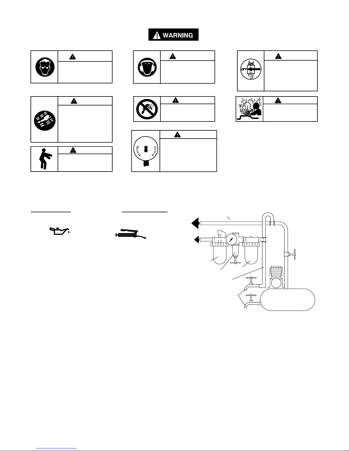
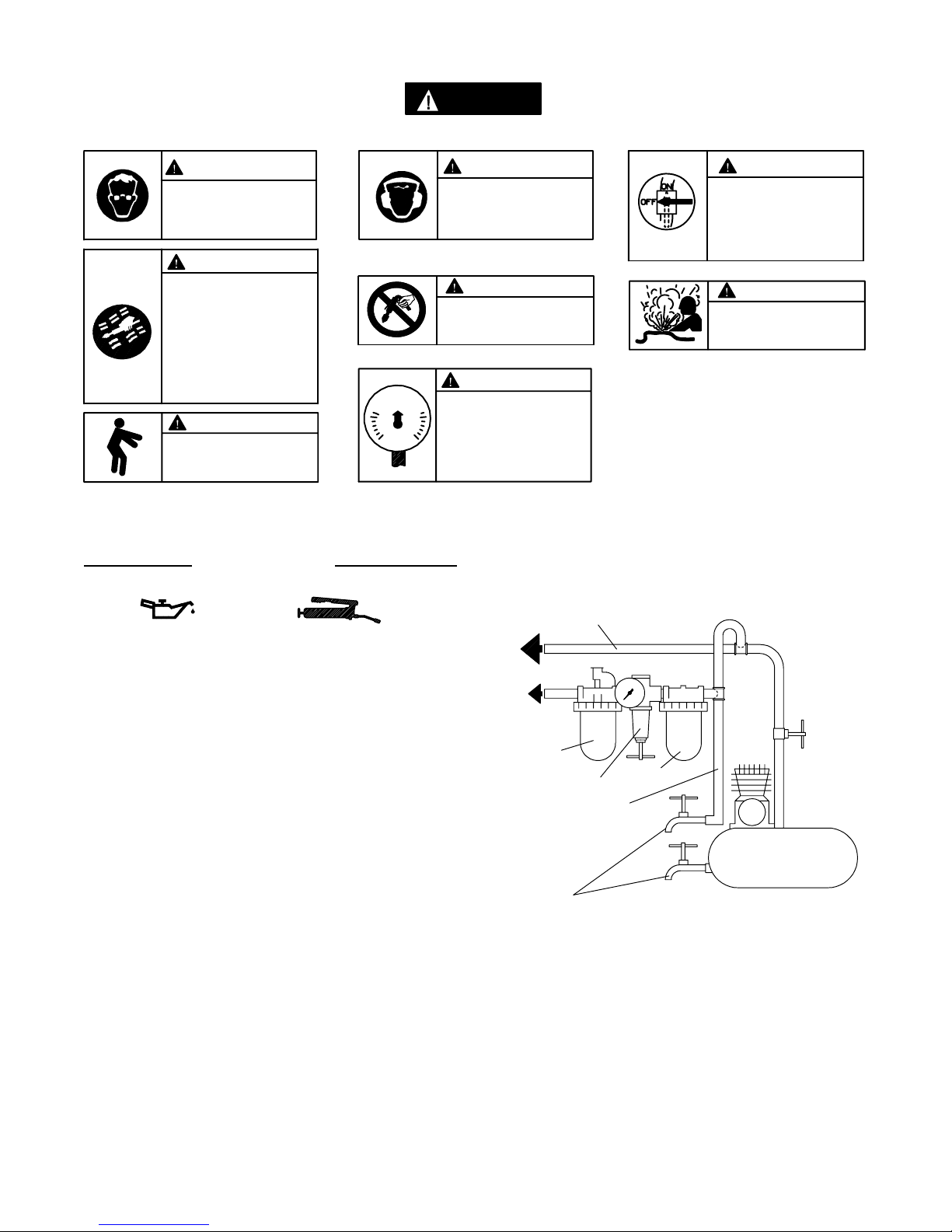
WARNING LABEL IDENTIFICATION
FAILURE TO OBSERVE THE FOLLOWING WARNINGS COULD RESULT IN INJURY.
WARNING
Always wear eye protection
when operating or performing mainten an ce on this
tool.
WARNING
Always wear hearing
protection when operating
this tool.
WARNING
Always turn off the air supply and disconnect the air
supply hose before installing, removing or adjusting
any accessory on this tool,
or before performing any
maintenance on this tool.
WARNING
Air powered tools can vibrate
in use. Vibration, repetitive
motions or uncomfortable positions may be harmful to your
hands and arms. Stop using
any tool if discomfort, tingling
feeling or pain occurs. Seek
medical advice before resuming use.
90 psig
(6.2bar/620kPa)
WARNING
Keep body stance balanced
and f irm. Do not overreach
when operating this tool.
PLACING TOOL IN SERVICE
LUBRICATION
Ingersoll--Rand No. 10 Ingersoll--Rand No. 67
Always use an air line lubricator with these tools.
We recommend the following Filter--Lubricator--Regulator
Unit:
F o r U S A -- N o . C 0 8 -- 0 2 -- F K G 0 -- 2 8
After each 40,000 cycles or each month, whichever
occurs first, lubricate the gear train with Ingersoll--Rand
No. 67 Grease.
WARNING
Do not carry the tool by
the hose.
WARNING
Operate at 90 psig (6.2 bar/
620 kPa) Maximum air pressure.
MAIN LINES 3 TIMES
AIR TOOL INLET SIZE
TO
AIR
SYSTEM
TO
AIR
TOOL
LUBRICATOR
REGULATOR
BRANCH LINE 2 TIMES
AIR TOOL INLET SIZE
DRAIN REGULARLY
FILTER
WARNING
Do not use damaged, frayed
or deteriorated air hoses
and fittings.
COMPRESSOR
(Dwg. TPD905--1)
2
Page 3

PLACING TOOL IN SERVICE
SPECIFICATIONS
IN--LINE HANDLE WITH LEVER THROTTLE
Model Free Speed Chuck Capacity
rpm in mm
QS511, QS511B, QS511BD, QS511D 5,100 1/4 6
QS381, QS381B, QS381BD, QS381D 3,800 1/4 6
QS301, QS301B, QS301BD, QS301D 3,000 1/4 6
QS201, QS201B, QS201BD, QS201D 2,000 1/4 6
QS151, QS151B, QS151BD, QS151D 1,500 1/4 6
QS091, QS091B, QS091BD, QS091D 900 1/4 6
QS051, QS051B, QS051BD, QS051D 500 1/4 6
3
Page 4
F
MANUEL D’EXPLOITATION ET D’ENTRETIEN
DES PERCEUSES PNEUMATIQUES DE LA SÉRIE QS
NOTE
Les perceuses de la Série QS sont destinées aux opérations de perçage dans les industries de
l’aérospatiale, de l’automobile, des appareils ménagers, de l’électronique, de l’usinage et des
meubles.
Ingersoll--Rand ne peut être tenu responsable de la modification des outils par le client pour les
adapter à des applications qui n’ont pas été approuvées par Ingersoll--Rand.
ATTENTION
D’IMPORTANTES INFORMATIONS DE SÉCURITÉ SONT JOINTES.
LIRE CE MANUEL AVANT D’UTILISER L’OUTIL.
L’EMPLOYEUR EST TENU DE COMMUNIQUER LES INFORMATIONS
DE CE MANUEL AUX EMPLOYÉS UTILISANT CET OUTIL.
LE NON RESPECT DES A VERTISSEMENTS SUIVANTS PEUT CAUSER DES BLESSURES.
MISE EN SERVICE DE L’OUTIL
• Toujours exploiter, inspecter et entretenir cet outil
conformément au Code de sécurité des outils
pneumatiques portatifs de l’American National
Standards Institute (ANSI B186.1).
• Pour la sécurité, les performances optimales et la
durabilité maximale des pièces, cet outil doit être
connecté à une alimentation d’air comprimé de 6,2 bar
(620 kPa) maximum à l’entrée , avec un flexible de 6 mm
de diamètre intérieur .
• Couper toujours l’alimentation d’air comprimé et
débrancher le flexible d’alimentation avant d’installer,
déposer ou ajuster tout accessoire sur cet outil, ou
d’entreprendre une opération d’entretien quelconque
sur l’outil.
• Ne pas utiliser des flexibles ou des raccords
endommagés, effilochés ou détériorés.
• S’assurer que tous les flexibles et les raccords sont
correctement dimensionnés et bien serrés. Voir Plan
TPD905--1 pour un exemple type d’agencement des
tuyauteries.
• Utiliser toujours de l’air sec et propre à une pression
maximum de 6,2 bar (620 kPa). La poussière, les fumées
corrosives et/ou une humidité excessive peuvent
endommager le moteur d’un outil pneumatique.
• Ne jamais lubrifier les outils avec des liquides
inflammables ou volatiles tels que le kérosène, le gasoil
ou le carburant d’aviation.
• Ne retirer aucune étiquette. Remplacer toute étiquette
endommagée.
UTILISA TION DE L’OUTIL
• Porter toujours des lunettes de protection pendant
l’utilisation et l’entretien de cet outil.
• Porter toujours une protection acoustique pendant
l’utilisation de cet outil.
• Tenir les mains, les vêtements flous et les cheveux longs,
éloignés de l’extrémité rotative de l’outil.
• Prévoir, et ne pas oublier, que tout outil motorisé est
susceptible d’à--coups brusques lors de sa mise en
marche et pendant son utilisation.
• Garder une position équilibrée et ferme. Ne pas se
pencher trop en avant pendant l’utilisation de cet outil.
Des couples de réaction élevés peuvent se produire à, ou
en dessous, de la pression d’air recommandée.
• La rotation des accessoires de l’outil peut continuer
pendant un certain temps après le relâchement de la
gâchette.
• Les outils pneumatiques peuvent vibrer pendant
l’exploitation. Les vibrations, les mouvements répétitifs
et les positions inconfortables peuvent causer des
douleurs dans les mains et les bras. N’utiliser plus
d’outils en cas d’inconfort, de picotements ou de
douleurs. Consulter un médecin avant de recommencer
à utiliser l’outil.
• Utiliser les accessoires recommandés par Ingersoll-Rand.
• Cet outil n’est pas conçu pour fonctionner dans des
atmosphères explosives.
• Cet outil n’est pas isolé contre les chocs électriques.
L ’utilisation de rechanges autres que les pièces d’origine Ingersoll--Rand peut causer des risques d’insécurité, réduire les
performances de l’outil et augmenter l’entretien, et peut annuler toutes les garanties.
Les réparations ne doivent être effectuées que par des réparateurs qualifiés autorisés. Consultez votre Centre de Service
Ingersoll--Rand le plus proche.
Adressez toutes vos communications au Bureau
Ingersoll--Rand ou distributeur le plus proche.
Ingersoll--Rand Company, 2002
Imprimé aux É.U.
NOTE
Page 5
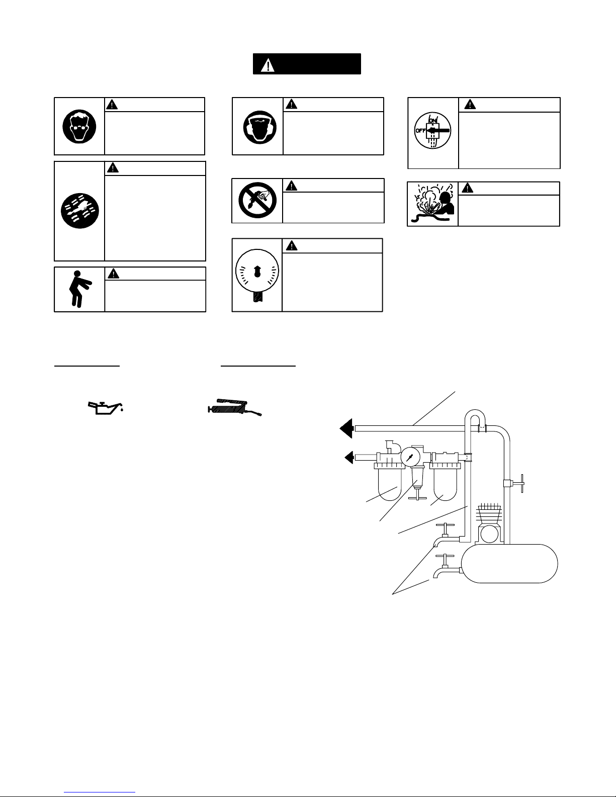
SIGNIFICATION DES ÉTIQUETTES D’AVERTISSEMENT
Y
A
A
L
ATTENTION
LE NON RESPECT DES AVERTISSEMENTS SUIVANTS PEUT CAUSER DES BLESSURES.
ATTENTION ATTENTION
Porter toujours des lunettes
de protection pendant
l’utilisation et l’entretien de
cet outil.
Porter toujours une
protection acoustique
pendant l’utilisation de cet
outil.
ATTENTION
Les outils pneumatiques
peuvent vibrer pendant
l’exploitation. Les vibrations,
les mouvements répétitifs et les
positions inconfortables
peuvent causer des douleurs
dans les mains et les bras.
N’utiliser plus d’outils en cas
d’inconfort, de picotements ou
de douleurs. Consulter un
médecin avant de recommencer
à utiliser l’outil.
ATTENTION
Garder une position équilibrée et
ferme. Ne pas se pencher trop
en avant pendant
l’utilisation de cet outil.
90 psig
(6.2bar/620kPa)
Ne pas transporter l’outil
par son flexible.
Utiliser de l’air comprimé
à un e pression maximum
de 6,2 bar (620 kPa).
MISE EN SERVICE DE L’OUTIL
LUBRIFICATION
ATTENTION
ATTENTION
VERS LE
RÉSEAU D’AIR
COMPRIMÉ
ATTENTION
Couper toujours l’alimentation
d’air comprimé et débrancher le
flexible d’alimentation avant
d’installer, déposer ou ajuster
tout accessoire sur cet outil, ou
d’entreprendre une opération
d’entretien quelconque sur l’outil.
ATTENTION
Ne pas utiliser des flexibles ou
des raccords endommagés,
effilochés o u détériorés.
TU
UTERIE PRINCIP
AU MOINS 3 FOIS LA DIMENSION DE L’ADMISSION D’AIR
DE L’OUTIL
E
Ingersoll--Rand No. 10 Ingersoll--Rand No. 67
Utiliser toujours un lubrificateur avec ces outils. Nous
recommandons l’emploi du filtre--régulateur--lubrificateur
suivant:
É . U . -- N o . C 0 8 -- 0 2 -- F K G 0 -- 2 8
Tous les 40.000 cycles ou au moins tous les mois, lubrifier
le train d ’engrenages avec de la graisse Ingersoll--Rand
No. 67.
VERS
L’OUTIL
PNEU-
MATIQUE
LUBRIFICATEUR
FILTRE
RÉGULATEUR
LIGNE SECONDAIRE AU
MOINS 2 FOIS LA DIMEN-
SION DE L’ADMISSION
D’AIR DE L’OUTIL
VIDANGER
RÉGULIÈREMENT
COMPRESSEUR
(Plan TPD905--1)
5
Page 6

MISE EN SERVICE DE L’OUTIL
SPÉCIFICATIONS
Modèle
QS511, QS511B, QS511BD, QS511D en ligne 5.100 1/4 6
QS381, QS381B, QS381BD, QS381D en ligne 3.800 1/4 6
QS301, QS301B, QS301BD, QS301D en ligne 3.000 1/4 6
QS201, QS201B, QS201BD, QS201D en ligne 2.000 1/4 6
QS151, QS151B, QS151BD, QS151D en ligne 1.500 1/4 6
QS091, QS091B, QS091BD, QS091D en ligne 900 1/4 6
QS051, QS051B, QS051BD, QS051D en ligne 500 1/4 6
Type de
poignée
Vitesse
àvide
tr/mn pouces mm
Capacité du
mandrin
6
Page 7
E
MANUAL DE FUNCIONAMIENTO Y MANETNIMIENTO
PARA TALADROS NEUMÁTICOS DE LA SERIE QS
NOTA
Los taladros de la serie QS están diseñados para las operaciones de taladrado en las industrias
aeroespacial, del automóvil, de electrodomésticos, electrónica, mecánica y del mueble.
Ingersoll--Rand no aceptará responsabilidad alguna por la modificación de las herramientas
efectuada por el cliente para las aplicaciones que no hayan sido consultadas con Ingersoll--Rand.
AVISO
SE ADJUNTA INFORMACIÓN IMPORTANTE DE SEGURIDAD.
LEA ESTE MANUAL ANTES DE UTILIZAR LA HERRAMIENTA.
ES RESPONSABILIDAD DE LA EMPRESA ASEGURARSE DE QUE EL
OPERARIO ESTÉ AL TANTO DE LA INFORMACIÓN QUE CONTIENE ESTE MANUAL.
EL HACER CASO OMISO DE LOS AVISOS SIGUIENTES PODRÍA OCASIONAR LESIONES.
P ARA PONER LA HERRAMIENTA EN SERVICIO
• Utilice, examine y mantenga siempre esta herramienta
conforme al código de seguridad para herramientas
neumáticas portátiles de la American Natio nal
Standards Institute (ANSI B186.1).
• Para mayor seguridad, rendimiento óptimo y larga
vida útil de las piezas, utilice esta herramienta a una
presión de aire máxima de 90 psig (6,2 bar/620 kPa)
con una manguera de suministro de aire con diámetro
interno de 6 mm.
• Corte siempre el suministro de aire y desconecte la
manguera de suministro de aire antes de instalar,
desmontar o ajustar cualquier accesorio de esta
herramienta, o antes de realizar cualquier operación de
mantenimiento de la misma.
• No utilice mangueras de aire y racores dañados,
desgastados o deteriorados.
• Asegúrese de que todos los racores y mangueras sean
del tamaño correcto y estén bien apretados. El Esq.
TPD905--1 muestra una disposición característica de las
tuberías.
• Use siempre aire limpio y seco a una presión máxima
de 90 psig (6,2 bar/620 kPa). El polvo, los gases
corrosivos y el exceso de humedad pueden estropear el
motor de una herramienta neumática.
• No lubrique las herramientas con líquidos inflamables
o volátiles tales como queroseno, gasoil o combustible
para motores a reacción.
• No saque ninguna etiqueta. Sustituya toda etiqueta
dañada.
UTILIZACIÓN DE LA HERRAMIENTA
• Use siempre protección ocular cuando utilice esta
herramienta o realice operaciones de mantenimiento
en la misma.
• Use siempre protección para los oídos cuando utilice
esta herramienta.
• Mantenga las manos, la ropa suelta y el cabello largo
alejados del extremo giratorio de la herramienta.
• Anticipe y esté atento a los cambios repentinos en el
movimiento durante la puesta en marcha y utilización
de toda herramienta motorizada.
• Mantenga una postura del cuerpo equilibrada y firme.
No estire demasiado los brazos al manejar la
herramienta. Pueden darse elevados pares de reacción
a la presión de aire recomendada, e incluso a presiones
inferiores.
• Los accesorios de la herramienta podrían seguir
girando brevemente después de haberse soltado la
palanca de mando.
• Las herramientas neumáticas pueden vibrar durante el
uso. La vibración, los movimientos repetitivos o las
posiciones incómodas pueden dañarle los brazos y
manos. En caso de incomodidad, sensación de
hormigueo o dolor, deje de usar la herramienta.
Consulte con el médico antes de volver a utilizarla.
• Utilice únicamente los accesorios Ingersoll--Rand
recomendados.
• Esta herramienta no ha sido diseñada para trabajar en
ambientes explosivos.
• Esta herramienta no está aislada contra descargas
eléctricas.
El uso de piezas de recambio que no sean las auténticas piezas Ingersoll--Rand puede poner en peligro la seguridad, reducir el
rendimiento de la herramienta y aumentar los cuidados de mantenimiento necesarios, así como invalidar toda garantía.
Las reparaciones sólo se deben encomendar a personal debidamente cualificado y autorizado. Consulte con el centro de servicio
autorizado Ingersoll--Rand más próximo.
Toda comunicación se deberá dirigir a la oficina o
al distribuidor Ingersoll--Rand más próximo.
Ingersoll--Rand Company, 2002
Impreso en EE. UU.
NOTA
Page 8
ETIQUETAS DE AVISO
AVISO
EL HACER CASO OMISO DE LOS A VISOS SIGUIENTES PODRÍA OCASIONAR LESIONES.
ADVERTENCIA
Use siempre protección ocular
cuando utilice esta herramienta
o realice operaciones de
mantenimiento en la misma.
ADVERTENCIA
Las herramientas neumáticas
pueden vibrar durante el uso.
La vibración, los movimientos
repetitivos o las posiciones
incómodas podrían dañarle los
brazos y las manos. En caso
de in co modid ad , sensación de
hormigueo o dolor, dejar de
usar la herramienta. Consultar
al médico antes de volver a uti lizarla.
90 psig
(6.2bar/620kPa)
ADVERTENCIA
Mantener una postura del cuerpo
equilibrada y firme. No estirar d e masiado los brazos al manejar la
herramienta.
PARA PONER LA HERRAMIENTA EN SERVICIO
LUBRICACIÓN
Ingersoll--Rand Nº 10 Ingersoll--Rand Nº 67
ADVERTENCIA
Use siempre protección para
los o íd o s cuando utilice esta
herramienta.
ADVERTENCIA
No coger la herramienta
por la manguera para levantarla.
ADVERTENCIA
Manejar la herramienta a una
presión de aire máxima de 90
psig (6,2 bar/620 kPa).
AL SISTEMA
NEUMÁTICO
ADVERTENCIA
Cortar siempre el suministro
de aire y desconectar la manguera de suministro de aire
antes de instalar, retirar o ajustar cualquier accesorio de esta
herramienta, o antes de realizar
cualquier operación de mantenimiento de la misma.
ADVERTENCIA
No utilizar mangueras de aire
y accesorios dañados, des gastados ni deteriorados.
TUBERÍAS PRINCIPALES 3
VECES EL TAMAÑO DE
ENTRADA DE HERRAMIENTA
NEUMÁTICA
Utilice siempre un lubricador de aire comprimido con estas
herramientas. Recomendamos utilizar el siguiente co njunto
de filtro--lubricador--regulador:
P a r a E E . U U . -- N o . C 0 8 -- 0 2 -- F K G 0 -- 2 8
Después de cada 40.000 ciclos o mensualmente (lo que
ocurra primero), lubrique el tren de engranajes con grasa
Ingersoll--Rand Nº 67.
ALA
HERRA-MIENTA
NEUMÁTICA
LUBRICADOR
REGULADOR
TUBERÍADERAMAL
2 VECES EL TAMAÑO
DE ENTRADA DE
HERRAMIENTA
NEUMÁTICA
PURGAR
PERIÓDICAMENTE
FILTRO
COMPRESOR
(Esq. TPD905--1)
8
Page 9

PARA PONER LA HERRAMIENTA EN SERVICIO
ESPECIFICACIONES
Modelo
QS511, QS511B, QS511BD, QS511D recta 5.100 6 1/4
QS381, QS381B, QS381BD, QS381D recta 3.800 6 1/4
QS301, QS301B, QS301BD, QS301D recta 3.000 6 1/4
QS201, QS201B, QS201BD, QS201D recta 2.000 6 1/4
QS151, QS151B, QS151BD, QS151D recta 1.500 6 1/4
QS091, QS091B, QS091BD, QS091D recta 900 6 1/4
QS051, QS051B, QS051BD, QS051D recta 500 6 1/4
Tipo de
empuñadura
Velocidad en vacío Capacidad del
portabrocas
rpm mm pulg.
9
Page 10
MANUAL DE FUNCIONAMENTO
E MANUTENÇÃO PARA OS BERBEQUINS
PNEUMÁTICOS SÉRIES QS
AVISO
Os Berbequins Séries QS são concebidos para aplicações de perfuração em indústrias
aeroespacial, de automóveis, de equipamentos, electrónica, de maquinaria aeroespaciais e de
mobiliário.
A Ingersoll--Rand não é responsável por modificações, feitas pelo cliente em ferramentas, nas
quais a Ingersoll--Rand não tenha sido consultada.
ADVERTÊNCIA
INFORMAÇÃO DE SEGURANÇA IMPORTANTE EM ANEXO.
LEIA ESTE MANUAL ANTES DE OPERAR A FERRAMENTA.
É DA RESPONSABILIDADE DO EMPREGADOR COLOCAR A INFORMAÇÃO
DESTE MANUAL NAS MÃOS DO OPERADOR.
O NÃO CUMPRIMENTO DAS SEGUINTES ADVERTÊNCIAS PODE
RESULTAR EM FERIMENTOS.
P
COLOCANDO A FERRAMENTA
EM FUNCIONAMENTO
• Sempre opere, inspeccione e mantenha esta
ferramenta de a cordo com o Código de Segurança
do Instituto Americano de Padrões Nacionais para
Ferramentas Pneumáticas Portáteis (ANSI B186.1).
• Para segurança, máximo desempenho e máxima
durabilidade das peças, opere esta ferramenta com
uma pressão de ar máxima de 6,2 bar/620 kPa
(90psig) naentradadamangueira de alimentação
de ar com diâmetro interno de com 6 mm (1/4”).
• Desligue sempre a alimentação de ar e desconecte a
mangueira de alimentação de ar antes de instalar,
remover ou ajustar qualquer acessório nesta
ferramenta, ou antes de executar qualquer serviço
de manutenção nesta ferramenta.
• Não use mangueiras de ar ou adaptadores
danificados, gastos ou deteriorados.
• Certifique--se de que todas as mangueiras e
adaptadores sejam do tamanho correcto e estejam
apertados com firmeza. Veja o Desenho TPD905--1
para um arranjo típico de tubagem.
• Use sempre ar seco e limpo com pressão máxima de
90 psig. Pó, fumos corrosivos e/ou humidade excessiva
podem arruinar o motor de uma ferramenta
pneumática.
• Não lubrifique as ferramentas com líquidos
inflamáveis ou voláteis tais como querosene, diesel
ou combustível de jactos.
• Não remova nenhum rótulo. Reponha qualquer
rótulo danificado.
USANDO A FERRAMENTA
• Use sempre óculos de protecção quando estiver
operando ou executando serviço de manutenção nesta
ferramenta.
• Use sempre protecção contra ruído ao operar esta
ferramenta.
• Mantenha as mãos, partes do vestuário soltas e cabelos
compridos afastados da extremidade em rotação.
• Antecipe e esteja alerta a mudanças repentinas no
movimento quando ligar e operar qualquer
ferramenta motorizada.
• Mantenha a posição do corpo equilibrada e firme.
Não exagere quando operar esta ferramenta.
Torques de reacção elevados podem ocorrer na ou
abaixo da pressão de ar recomendada.
• Os acessórios da ferramenta podem continuar a
emitir impactos brevemente após a pressão ter sido
aliviada.
• Ferramentas accionadas pneumáticamente podem
vibrar em uso. Vibração, movimentos repetitivos ou
posições desconfortáveis podem ser prejudiciais às
mãos e aos braços. Pare de usar a ferramenta caso
ocorra algum desconforto, sensação de formigueiro ou
dor . Procure assistência médica antes de retornar ao
trabalho.
• Use acessórios recomendados pela Ingersoll--Rand.
• Esta Ferramenta não foi concebida para trabalhos
em atmosferas explosivas.
• Esta Ferramenta não está isolada contra choques
eléctricos.
O uso de peças de substituição que não sejam genuinamente da Ingersoll--Rand podem resultar em riscos de segurança,
diminuição do desempenho da ferramenta, aumento da necessidade de manutençã o e pode invalidar todas as garantias.
Asreparações devem ser feitas somente por pessoal treinado autorizado. Consulte o Centro de Serviços da Ingersoll--Rand
mais próximo.
Envie Todos os Comunicados Para o Distribuidor
ou Escritório da Ingersoll--Rand Mais Próximo.
Ingersoll--Rand Company, 2002
Impresso nos E.U.A.
AVISO
Page 11
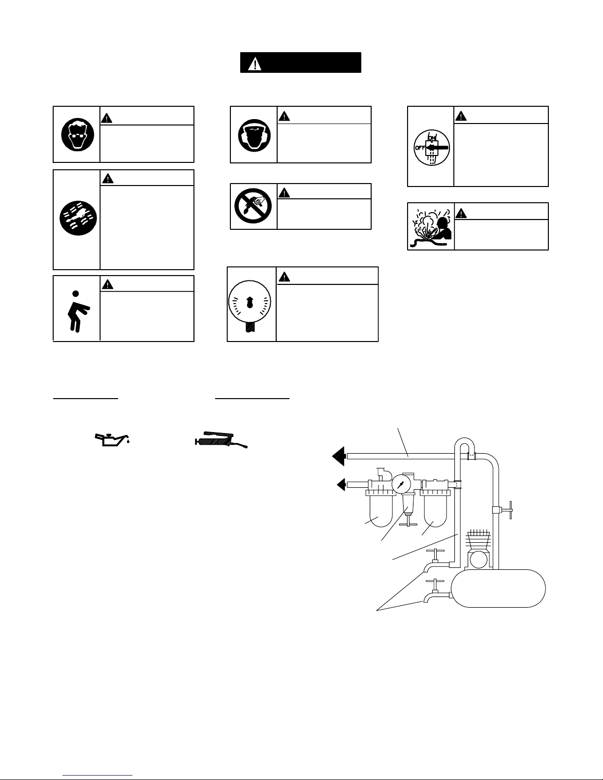
IDENTIFICAÇÃO DO RÓTULO DE ADVERTÊNCIA
ADVERTÊNCIA
O NÃO CUMPRIMENTO DAS SEGUINTES ADVERTÊNCIAS PODE
RESULTAR EM FERIMENTOS.
ADVERTÊNCIA
Use sempre óculos de protecção
quando estiver operando ou
executando algum serviço de
manutenção nesta ferramenta.
ADVERTÊNCIA
Usesempreprotecçãocontrao
ruído ao operar esta ferramenta.
ADVERTÊNCIA
Ferramentas accionadas
pneumáticamente podem vibrar
em uso. Vibração, movimentos
repetitivos ou posições
desconfortáveis podem ser
prejudiciais às mãos e aos
braços. Pare de usar a
ferramenta caso ocorra algum
desconforto, sensação de
formigueiro ou dor . Procure
assistência médica antes de
retornar ao trabalho.
ADVERTÊNCIA
Mantenha a posição do corpo
equilibrada e firme. Não
exagere quando operar esta
ferramenta. Torques de
reacção elevados podem
ocorrersobapressãodear
recomendada.
90 psig
(6.2bar/620kPa)
ADVERTÊNCIA
Não carregue a ferramenta
segurando na mangueira.
ADVERTÊNCIA
Opere com pressão do ar Máxima
de 90 psig (6,2--6,9 bar).
COLOCANDO A FERRAMENTA EM FUNCIONAMENTO
LUBRIFICAÇÃO
LINHAS PRINCIPAIS 3 VEZES O TAMANHO DA
PARA
SISTEMA DE AR
ENTRADADAFERRAMENTAPNEUMÁTICA
ADVERTÊNCIA
Desligue sempre a alimentação
de ar e desconecte a mangueira
de alimentação de ar antes de
instalar, remover ou ajustar
qualquer acessório nesta
ferramenta, ou antes de executar
algum serviço de manutenção
nesta ferramenta.
ADVERTÊNCIA
Não use mangueiras de ar ou
adaptadores danificados,
gastos ou deteriorados.
Ingersoll--Rand No. 10 Ingersoll--Rand No. 67
Use sempre um lubrificador de ar de linha com estas
ferramentas. Nós recomendamos a seguinte unidade
Filtro--Lubrificador--Regulador:
Para EUA -- No. C08--02--FKG0--28
Depois de 40.000 ciclos ou cada mês, o que ocorrer
primeiro, lubrifique o trem de engrenagem com Massa
Ingersoll--Rand No. 67.
PARA
FERRAMENTA
PNEUMÁTICA
LUBRIFICADOR
REGULADOR
LINHA RAMIFICADA
2 VEZES O TAMANHO
DA ENTRADA DA
FERRAMENTA
PNEUMÁTICA
DRENE
REGULARMENTE
11
FILTRO
COMPRESSOR
(Desenho TPD905--1)
Page 12

COLOCANDO A FERRAMENTA EM FUNCIONAMENTO
ESPECIFICAÇÕES
Modelo
QS511, QS511B, QS511BD, QS511D em linha 5.100 6 1/4
QS381, QS381B, QS381BD, QS381D em linha 3.800 6 1/4
QS301, QS301B, QS301BD, QS301D em linha 3.000 6 1/4
QS201, QS201B, QS201BD, QS201D em linha 2.000 6 1/4
QS151, QS151B, QS151BD, QS151D em linha 1.500 6 1/4
QS091, QS091B, QS091BD, QS091D em linha 900 6 1/4
QS051, QS051B, QS051BD, QS051D em linha 500 6 1/4
Tipo de
Punho
Velocidade
Livre
rpm mm pol.
Capacidade do
Encabadouro
12
Page 13
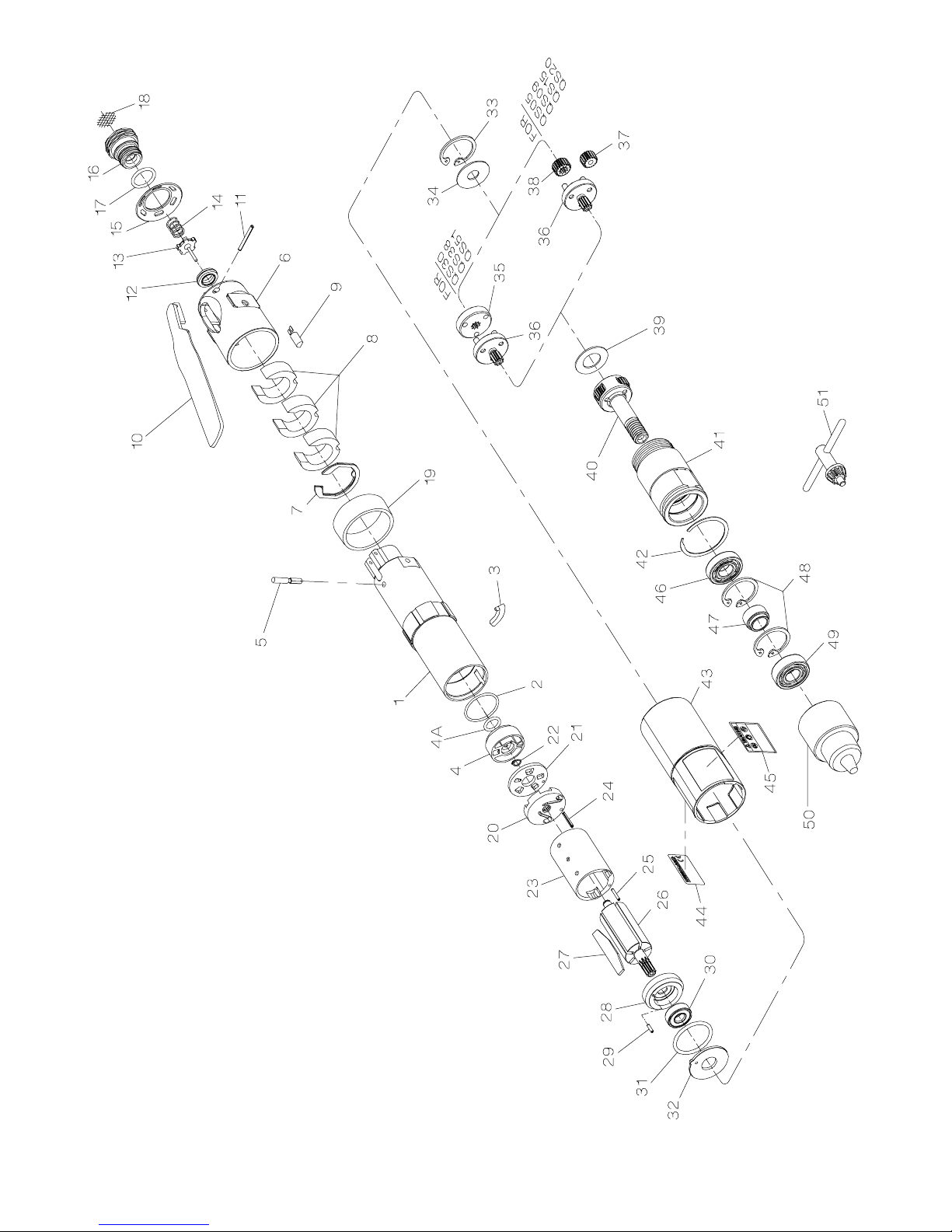
(Dwg. TPA1760)
SERIES QS DRILLS
13
Page 14
SERIES QS DRILLS
PART NUMBER FOR ORDERING PART NUMBER FOR ORDERING
1 MotorHousing ................................ TRL--40 23 CylinderAssembly ...................... TRH--A3--D
2 HousingO--ring ............................... TRH--104 24 CylinderRearAlignmentPin ........... TRH--98
3 HousingPlug ................................. TRD--982 25 CylinderFrontAlignmentPin ........... TRH--98--1
4 ReverseValveAssembly ........................ T RH--A3291 26 Rotor ................................. TRH--53
4A ReverseValveSeal ........................ R1A--159 27 VanePacket(setof5Vanes) ............... TRH--42--5
5 Throttle Plunger ............................... TRL--302 28 FrontEndPlateAssembly ................. TRH--A11
6 BackCap .................................... TRL--231 29 EndPlateAlignmentPin ............... TRH--98--2
for1/4--18NPTthread............. TRH--A465 forSeriesQS15 ............... TRH--A2169--12
for1/4--19BSPTthread ............ TRH--A465--B forSeriesQS38 ............... TRH--A216--12
havingamemorychip) ......................... TRH--800 33 GearRetainer ........................... TRH--28
7 BackCapGasket .............................. TRL--A283 30 FrontRotorBearing................... TRH--24
8 MufflerElement(3)............................ TRL --311 31 MotorSeal ............................. TRH--211
9 Memory Chip (only for models ending in D 32 MotorClampWasher..................... TRH--207
10 Throttle Lever ................................ TRL--273 34 Gear Head Spacer ....................... TRH--81
11 Throttle Lever Pin ............................. TRL--98 35 Planet Gear Head Drive Plate (for Series QS30,
12 Throttle Valve Seat ............................ TRH--303 QS38andQS51) ........................ TRH--17
13 Throttle Valve ................................ TRD--A302 36 Planet Gear Head Assembly (includes
14 Throttle Valve Spring ........................... TRL--51 gear shafts)
15 ExhaustDiffuser .............................. TRH--123 for Series QS05, QS09,
16 Inlet Bushing Assembly QS30andQS51 ............... TRH--A2169--16
17 InletBushingSeal ......................... AF120--290 forSeriesQS20 ............... TRH--A2169--10
18 InletScreen .............................. TRH--61 37 Planet Gear (3 for each Gear Head)
rotorbearing) ................................. TRH--A12--1 forSeriesQS20 ............... TRH--10--10
19 HousingPlugCover............................ TRD--981 forSeriesQS05andQS09 ....... TRH--10--16
20 Rear End Plate Assembly (includes rear forSeriesQS15 ............... TRH--10--12
21 RearEndPlateFacePlate ....................... TRH--12--2
22 RearEndPlateAssemblyRetainer ................ 8SL--305
14
Page 15
PART NUMBER FOR ORDERING PART NUMBER FOR ORDERING
forSeriesQS15 .................. TRH--17--18 44 Nameplate .......................... TRH--301
forSeriesQS20 .................. TRH--17--21 45 WarningLabel ....................... TRH--99
forSeriesQS05andQS30 ............ TRD--A8--16 49 SpindleCapBearing ..................... TRH--510
forSeriesQS38 .................... TRD--A8--15 50 DrillChuck(1/4”) ....................... R0H--99
forSeriesQS09,QS15andQS51 ...... TRD--A8--12 51 ChuckKey ............................. R1H--J253
forSeriesQS20 .................... TRD--A8--10 * DrillChuckGuardKit(1/4”optional) ....... TRD--A961--S
gearing) 48 BearingStop(2)......................... TRH--28
38 Gear Head Pinion 43 HousingGrip ........................... TRH--40--A136
39 Planet Gear Head Spacer ........................ TRH-- 82 46 SpindleBearing ......................... R00H--97
40 Spindle Assembly (includes all spindle 47 Spindle Bearing Spacer ................... TRD--111
41 GearCase .................................... TAD --37 * SuspensionBail ......................... 7L--365
42 GripRetainer ................................. TRH--197 * Piped--AwayExhaustKit(optional) ......... LG1--K284
* Not illustrated.
15
Page 16

MAINTENANCE SECTION
Always wear eye protection when operating or performing maintenance on this tool.
Always turn off the air supply and disconnect the air
supply hose before installing, removing or adjusting
any accessory on this tool, or before performing any
maintenance on this tool.
tion you need to rotate the Diffuser to obtain the desired
speed and then rotate it accordingly. Best results are
achieved by using gradual increments and frequent
tachometer readings. Be sure to turn off the air supply
and disconnect the line when making adjustments.
DISASSEMBLY
General Instructions
LUBRICATION
Each time a Series QS Drill is disassem bled for maintenance and repair or replacement of parts, lubricate the tool
as fo llows:
1. Coat all exposed gears with Ingersoll--Rand No. 67
Grease and work some of the Grease into the gearing
of the Spindle Assembly (40).
2. Use Ingersoll--Rand No. 10 Oil to lubricate the motor.
Inject approximately 1 to 2 cc of oil into the air inlet
before attaching the air hose to the tool.
SPEED ADJUSTMENT
Series QS Inline Drills are furnished with the ability to
precisely control speed, within certain ranges. Setting the
speed requires a tachometer. Therefore, the adjustment,
although simple, should only be attempted by a competent
technician using the proper equipment.
The Back Cap (6) has a small, molded stud on the end
face of the Cap nearest the Exhaust Diffuser (15). Take
an initial reading of the tool speed by applying a tachometer to the end of the Chuck (50) without a drill bit and
with the Lever (10) completely depressed. If the tachometer has a concave tip, close the Chuck completely; if the
tip is convex, open the Chuck completely.
After determining the actual velocity, shut off the air supply and disconnect the air line. Use a 3/4” wrench to
loosen the Inlet Bushing. The longest slot in the Exhaust
Diffuser will contain the molded stud on the Back Cap.
Rotate the Diffuser to open the exhaust po rts to increase
speed or rotate it to restrict the exhaust to reduce speed.
Being careful not to allow the Diffuser to damage the
molded stud, tighten the Inlet Bushing to 15 ft --lbs. (20
Nm) torque. Connect the air line and restore the air supply and check the velocity again. Determine which direc-
1. Do not disassemble the tool any further than necessary to replace or repair damaged parts.
2. Whenever grasping a tool or part in a vise, always use
leather--covered or copper--covered vice jaws to protect the surface of the part and help prevent distortion. This is particularly true of thread ed members
and housings.
3. Do not remove any part which is a press fit in or on a
subassembly unless the removal of that part is necessary for repairs or replacement.
4. Do not disassemble the tool unless you have a complete set of gaskets and o --rings for replacement.
Disassembly of the Tool
Each Series QS Leve r Inline Drill is made using three
modules or units which include a housing and throttle
unit, a motor unit and a combined gearing with spindle
unit. The tool can be disassembled for repairs to each
individual unit without disturbing the other units. To separate the modules, proceed as follows:
1. Remove the Chuck (50) using the following technique:
a) Insert the short leg of a 1/4” hex wrench into the
jaws of the Chuck and tighten the Chuck.
b) Using a brass hammer, sharply rap the long leg of
the wrench in a counterclockwise direction to
loosen the Chuck.
c) Unscrew and remove the Chuck from the spindle.
2. Use a thin blade screwdriver to spiral the Grip
Retainer (42) out of the groove in the Gear Case (41)
and pull the Housing Grip (43) off the front of the
tool.
3. Using a wrench on the flats of the Gear Case, unscrew and separate the Gear Case from the Motor
Housing (1).
16
Page 17

MAINTENANCE SECTION
4. Remove the Motor Clamp Washer (32) and the Motor
Seal (31) from the assembled motor in the Housing.
5. Tap the Motor Housing on a block of wood to remove
the motor assembly from the Motor Housing.
6. Lightly grasp the flats of the Motor Housing in leather-- covered or copper--covered vise jaws with the Inlet Bushing (16) upward.
7. Place a 1 --3/16” open end wrench on the flats of the
Back Cap (6) to prevent it from rotating, and use a
3/4” wrench to unscrew and remove the Inlet Bushing.
8. Lift the Exhaust Diffuser (15) off the Back Cap.
9. If the Throttle Valve Spring (14) did n ot come out of
the tool with the Inlet Bushing, use needle nose pliers
to remove it and the Throttle Valve (13) from the Motor Housing.
10. To remove the Throttle Valve Seat (12), insert a
hooked tool through the central opening of the Seat
and pull it from the Motor Housing.
11. Using a 1/16” pilot punch, tap the Throttle Lever Pin
(11) out of the Back Cap a nd remove the Throttle
Lever (10).
12. Pull the Throttle Plunger (5) out of the Motor Housing and remove the assembly from the vise.
13. Holding the assembly horizontally, remove the Back
Cap, the Memory Chip (9) (if included with the tool),
and the Back Cap Gasket (7).
14. If the Muffler Elements (8) need to be cleaned or replaced, pull them out of the Back Cap.
Disassembly of the G earing
1. Using snap ring pliers, remov e the Gear Retainer (33)
from inside the Gear Case and remove the Gear Head
Spacer (34).
2. For Series QS30, QS38 and QS51, lightly rap the
motor end of the Gear Case on a wooden work bench
top to remove the Planet Gear Head Drive Plate (35),
Planet Gear Head Assembly (36) and the Planet Gear
Head Spacer (39).
For Series QS05 and QS09, lightly rap the motor
end of the Gear Case on a wooden work bench top to
remove the three Planet Gears (37), the Planet Gear
Head Assembly (36) and the Planet Gear Head
Spacer (39).
For Series QS15 and QS20, lightly rap the motor
end of the Gear Case on a wooden work bench top to
remove the three Planet Gears (37), the Rotor Pinion
(38), the Planet Gear Head Assembly (36) and the
Planet Gear Head Spacer (39).
If the Spindle Assembly is being removed or replaced, the Spindle Bearing and Spindle Cap
Bearing may be damaged during the removal process. We recommend that new replacement bearings be available for installation when the tool is
reassembled.
3. Stand the Gear Case on the table of an arbor press
with the threaded end of the Spindle Assembly (40)
upward. Using a rod slightly smaller than the spindle
shaft, press the Spindle Assembly out of the Spindle
Cap Bearing (49) and Spindle Bearing (46).
4. Insert a long, small drift through the central opening
of the Spindle Bearing and push the Bearing Spacer
(47) off to one side. Using a hammer with the drift,
tap the inner ring of the Spindle Cap Bearing. Repeat
the p rocess at several points until the Bearing is free
from the Gear Case. Remove the Bearing Spacer
from the Gear Case.
5. Using snap ring pliers, remove the two Bearing Stops
(48).
6. Stand the Gear Case on the table of an arbor press
with the threaded end upward, and press the Spindle
Bearing out of the Gear case.
Disassembly of the Motor
1. If the motor was not removed from the Housing (1)
when the tool was disassembled, slide the Motor
Clamp Washer (32) off the shaft of the Rotor (26)
and remove the Motor Seal (31).
2. Tap the Motor Housing on a block of wood to remove
the motor assembly from the Motor Housing.
3. Using snap r ing pliers, remove th e Rear End Plate
Assembly Retainer (22) from the shaft of the Rotor.
4. Pull the Rear End Plate Face Plate (20) and Rear End
Plate Assembly (21) off the hub of the Rotor.
5. Using a piece of leather or other type of protective
material, grasp the shaft of the Rotor and pull the
Rotor out of the Cylinder (23).
17
Page 18

MAINTENANCE SECTION
6. Remove the Vanes (27) from the Rotor.
7. Support the Front End Plate Assembly (28), as near
the rotor body as possible, on the table of an arbor
press and press the Rotor from the Front Rotor Bearing (30). Remove the Bearing from the Front End
Plate.
Disassembly of the Housing
1. Pull the Housing Plug Cover (19) off the inlet end of
the Motor Housing (1).
2. If the Housing Plug (3) does not drop out of the
Housing when the Cover is removed, tap the inlet end
of the Housing on a block of wood to dislodge the
Plug from the Housing.
3. Insert a 5/16” wooden dowel between 6 and 8 inches
long, into the inlet end of the Motor Housing and
push the Reverse Valve Assembly (4) out the motor
end of the Housing.
4. Use a hooked tool to pull the Housing O--ring (2) out
of the Motor Housing.
ASSEMBLY
General Instructions
1. Always press on the inner ring of a ball--type bearing
when installing the bearing on a shaft.
2. Always press on the outer ring of a ball --type bearing
when pressing the bearing into a bearing recess.
3. Whenever grasping a tool or part in a vise, always use
leather--covered or copper--covered vise jaws to protect the surface of the part and help prevent distortion. This is particularly true of thread ed members
and housings.
4. Except for bearings, always clean every part and wipe
every part with a thin film of oil before installation.
5. Apply o--ring lubricant to all o--rings before final assembly.
6. Check every bearing for roughness. If an open bearing must be cleaned, wash it thoroughly in a clean,
suitable cleaning solution and dry with a clean cloth.
Sealed or shielded bearings should never be
cleaned. Work grease into every open bearing before
installation.
Assembly of the Housing
1. Lubricate the Housing O--ring (2) with o--ring lubricant and install it at the bottom of the cylinder bore in
the Motor Housing (1).
2. Inspect the face and o--ring on the hub of the Reverse
Valve Assembly (4) for nicks or damage. Replace the
Reverse Valve Assembly if any damage is evident.
3. Lubricate the o --ring on the hub of the Reverse Valve
Assembly with o--ring lubricant and insert the Assembly, o--ring end leading, into the cylinder bore of the
Motor Housing. Push the Assembly toward the bottom of the cylinder bore until it “snaps” into its proper location.
4. While holding the Motor Housing with the inlet end
facing you and the reverse valve slot upward, rotate
the Reverse Valve Assembly until the threaded hole
in the v alve body is positioned at the right hand edge
of the slot.
5. Insert the pin end of the Housing Plug (3) into the
hole in the Reverse Valve while fitting th e remainder
of the Plug into the recess in the Motor Housing.
6. While holding the Plug in position, from the inlet end
of the Housing, slide the Housing Plug Cover (19)
onto the Housing. Make certain it captures the Plug
when it moves along the Housing and stops against
the housing shoulder.
Assembly of the Motor
1. Place the Front End Plate (28) on the splined shaft of
the Rotor (26) with the bearing recess away from the
rotor body.
2. Place the Front Rotor Bearing (30) onto the shaft and
using a sleeve or piece of tubing that contacts the
inner race of the Bearing, press the Bearing onto the
shaft until the Front End Plate nearly contacts the
rotor body.
In the following step, the measurement must be
made at the end corner of the large rotor body.
3. The clearance between the Front End Plate and Rotor
is critical. While pressing down with your finger on
the outer edge of the Front End Plate on the bearing
side, insert a 0.004” (0.1 mm) feeler gauge between
the face of the rotor body and the face of the End
Plate at a point that is 180 degrees from where the
pressure is applied. Refer to Dwg. TPA1740. To
increase the gap, support the End Plate and lightly tap
the rotor shaft with a plastic hammer; to decrease the
gap, press the Bearing farther onto the rotor shaft.
18
Page 19
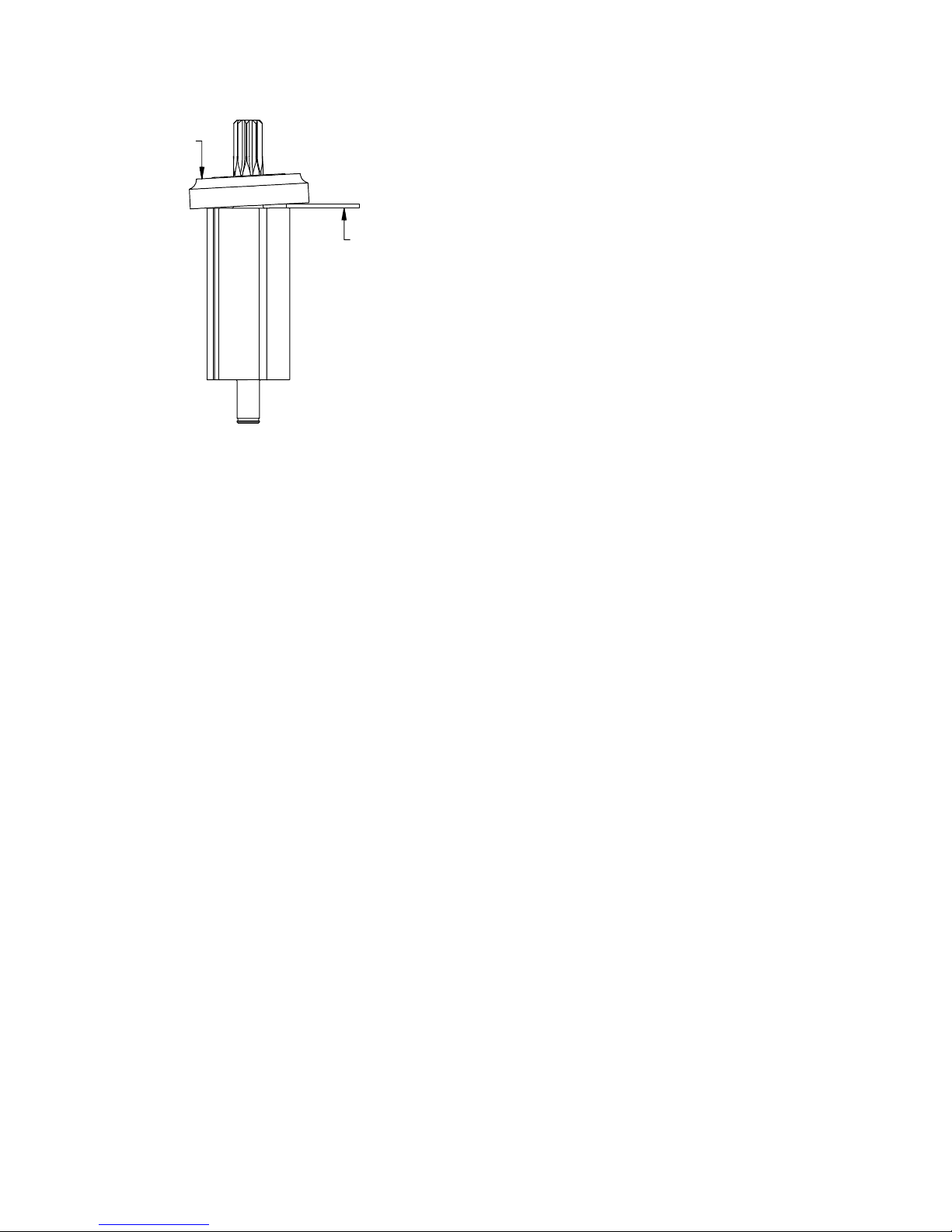
MAINTENANCE SECTION
Measurement of Front End Plate Clearance
PRESSURE
FEELER
GAUGE
(Dwg. TPA1740)
4. Wipe each Vane (27) with a light film of Ingersoll-Rand No. 10 Oil and place a Vane in each slot in the
Rotor.
5. One end of the Cylinder Assembly (23) has a notch
that breaks the outer wall and end face of the Cylinder. With that end trailing, install the Cylinder Assembly over the Rotor and Vanes against the Front
End Plate. M ake certain the Cylinder Front Alignment Pin (25) enters the hole in the Front End Plate.
6. Install the Rear End Plate Assembly (20), flat face
leading, on the rear hub of the Rotor. Make certain
the Cylinder Rear Alignment Pin (24) enters the hole
in the Rear End Plate.
7. Examine the Rear End Plate Face Plate (21) for
scratches. If it is scratched, replace it. If it is not,
slide it onto the rear hub of the Rotor and onto the
Cylinder Rear Alignment Pin against the Rear End
Plate. Some pressure may be required to fit the hole
in the Plate onto the Alignment Pin.
8. Using snap ring pliers, install the Rear End Plate Assembly Retainer (22) in the annular groove on the
rear rotor hub to secure the assembly in position.
9. Set the assembled motor aside.
Assembly of the Gearing
1. Work some Ingersoll--Rand No. 67 Grease into the
gearing of the Spindle Assembly (40).
2. Insert the threaded end of the Spindle Assembly into
the threaded end of the Gear Case (41) while meshing
the teeth of the gears with the spline inside the Gear
Case.
3. Support the gear end of the Spindle Assembly on the
table o f an arbor press while leaving clearance for the
Gear Case. Using a piece of tubing that will clear the
shaft and contact the inner ring of the Spindle Bearing (46), press the Bearing onto the shaft of the
Spindle Assembly until it contacts the gear hub.
4. Using snap ring pliers, install one of the Bearing
Stops (48) in the internal groove nearest the Bearing.
5. Apply some Ingersoll--Rand No. 67 Grease to the
Bearing Spacer (47) and slide it onto the shaft of the
Spindle Assembly with the smaller end trailing.
6. Using snap ring pliers, install the second Bearing
Stop in the internal gear case groove nearest the
threaded spindle end.
7. Stand the assembled Gear Case on the table of an
arbor press with the output Spindle upward. Install
the Spindle Cap Bearing (49) over the output shaft,
and using a piece of tubing that contacts the outer
ring of the Bearing, press the Bearing into the Gear
Case against the Bearing Stop.
8. Insert the Planet Gear Head Spacer (39) and Planet
Gear Head Assembly (36), spline hub leading into the
open end of the Gear Case.
9. For Series QS05, QS09, QS15 and QS20, apply
Ingersoll--Rand No. 67 Grease to the three Planet
Gears (37) and install them on the shafts of the Planet
Gear Head Assembly.
10. For Series QS15 and QS20, apply Ingersoll--Rand
No. 6 7 Grease to the Gear Head Pinion (38) and
while meshing the gear teeth, insert it in the opening
between the three Planet Gears.
11. For Series QS30, QS38 and QS51, install the Planet
Gear Head Drive Plate (35) on the shafts of the Planet
Gear Head Assembly.
12. Place the Gear Head Spacer (34) in the Gear Case
and secure the assembly by using snap ring pliers to
install the Gear Retainer (33) in the annular groove
inside the Gear Case.
Assembly of the Tool
1. Lightly grasp the flats on the Motor Housing (1) in
leather--covered or copper--covered vise jaws with the
inlet end of the tool upward.
2. Insert a 5/8” dowel through the opening in the Back
Cap (6), and using the dowel as an alignment d evice,
install the three Muffler Elements (8) in the cavity of
the Back Cap. Make certain the no tches in the outer
edge of the Elements fit over the memory chip pocket
in the bottom of the Cap.
19
Page 20

MAINTENANCE SECTION
3. If the tool is equipped with a Memory Chip (9),
install it (with the leads entering first) in the pocke t at
the bottom of the Back Cap.
4. Make certain the tab on the inside edge of the Back
Cap Gasket (7) is aligned with the pocket for the
Memory Chip and install the Gasket, metal face leading, in the r ecess of the Back Cap against the face
with the cavity containing the Muffler Elements.
5. Position the gasket end of the alignment dowel
against the inlet hub on the Motor Housing. Align
the flats on the Cap with the flats on the Housin g.
Orient the Back Cap and slide the Back Cap Assembly off the alignment dowel and onto the Motor
Housing.
6. The Exhaust Diffuser (15) has one slot that is longer
than the other five slots. The Back Cap has a short,
molded stud projecting from inlet end. Place the Exhaust Diffuser against the Back Cap with the long slot
encircling the molded stud. Rotate the Diffuser counterclockwise until the wall of the slot stops against
the stud. The exhaust ports are now in the full open
position which will provide maximum free speed.
7. Being careful not to damage it, insert the T hrottle
Valve Seat (12) into the central opening at th e in let
end of the Motor Housing at an angle until it clears
the threads in the Housing. Using a rod with a flat
end and no sharp edges, push the Seat to the bottom
of the opening until it seats flush.
8. Using needle nose pliers, insert the Throttle Valve
(13), long stem leading, into the opening against the
Seat. Center the Valve in the Seat.
9. Install the Throttle Valve Spring ( 14) in the opening
so that it encircles the Valve.
10. If the I nlet Screen (18) required replacement, use a
wooden dowel to carefully push a new one into the
Inlet Bushing (16).
11. If the Inlet Bushing Seal (17) is nicked or damaged,
carefully install a new one over the threads of the
Inlet Bushing.
12. Thread the Inlet Bushing Assembly through the Diffuser and Back Cap into the Motor Housing. Using a
1--3/16” wrench on the flats of the Back Cap to keep
it from turning, tighten the Inlet Bushing between 15
and20ft--lbs.(20and27Nm)torque.
13. The Throttle Plunger ( 5 ) h as a lengthwise flat on the
outer edge at one end of the Plunger. Insert the
Plunger, flat end first, into the cross hole in the Hous-
ing. Push on the end of the Plunger to make certain it
springs back from contact with the stem of the
Throttle Valve.
14. Position the Throttle Lever (1 0) in the slot in the
Back Cap and Motor Housing and using a 1/16” diameter rod, align the holes through the Back Cap,
Motor Housing and Throttle Lever. While maintaining alignment, install the Throttle Lever Pin (11) in
place of the rod by tapping it through all three pieces.
15. Remove the assembled Housing from the vise jaws.
16. Lightly grasp the flats at the inlet end of the Motor
Housing in leather--covered or copper--covered vise
jaws with the motor bore upward.
17. Grasp the spline of the Rotor (26) in the assembled
motor and after aligning the End Plate Alignment Pin
(29) with the internal notch in the motor end of the
housing bore, insert the assembled motor into the
Motor Housing. Make certain the motor is far
enough into the Housing to have the undercut below
the internal housing thread visible.
18. Lubricate the Motor Seal (31) with o--ring lubricant
and install it around the Front End Plate (28) and into
the undercut in the Housing.
19. Align the tab of the Motor Clamp Washer (32) with
the internal notch in the Housing and install it over
the rotor hub and End Plate Alignment Pin against the
Motor Seal. Make certain the Pin enters the hole in
the Washer and the Washer is flat against the Seal.
20. Apply some Ingersoll--Rand No. 67 Grease to the
spline on the rotor shaft.
21. Thread the assembled Gear Case (41) and Spindle
Assembly (40), gear case end leading, into the Motor
Housing and tighten the joint between 15 and 20 ft-lbs. (20 and 27 Nm) torque.
22. Install the Housing Grip (43), internal slotted end
leading, over the Gear Case and Housing and engage
the slots in the Grip with the projections on the Housing.
23. Install the Grip Retainer (42) in the groove on the
Gear Case to secure the Grip.
24. Remove the tool from the vise jaws and thread the
Chuck (50) onto the Spindle.
25. Check the free speed of the tool using a tachometer
and following the instructions in the SPEED AD-
JUSTMENT section of this manual.
20
Page 21

TROUBLESHOOTING GUIDE
Trouble Probable Cause Solution
Loss of Power Low air pressure Check air supply. For top performance, the air
pressure must be 90 psig (6.2 bar/620 kPa) at the
inlet.
Plugged Inlet Bushing Screen Clean the Inlet Bushing Screen using a clean,
suitable cleaning solution. If the Screen cannot be
cleaned, replace it.
Worn or broken Vanes Replace a complete set of Vanes.
Worn or broken Cylinder Replace the Cylinder if it is cracked or if the bore
appears wavy or scored.
Exhaust control restricted Make certain the Exhaust Diffuser is in the fully
open position.
Motor won’t run Motor Clamp Washer binding Remove the Gear Case make certain the Washer is
flat and the Motor Seal is properly positioned.
Gears binding Clean and inspect all g earing. Replace any worn or
damaged gearing.
Leaky Throttle Valve Worn Throttle Valve and/or
Throttle Valve Seat
Dirt accumulation on Throttle
Valve and/or Throttle Valve Seat
Gear Case gets hot Excessive grease Clean and inspect Gear Case and gearing parts and
Worn or damaged parts Clean and inspect the Gear Case and gearing.
Install a new Valve and/or Seat.
Clean or replace the Throttle Valve and /or Throttle
Valve Seat.
lubricate as instructed.
Replace worn or broken components.
SAVE THESE INSTRUCTIONS. DO NOT DESTROY.
21
Page 22

22
Page 23

23
Page 24

 Loading...