

Page 1
Form P7775
Edition 1
April, 2004
CCN 04580973
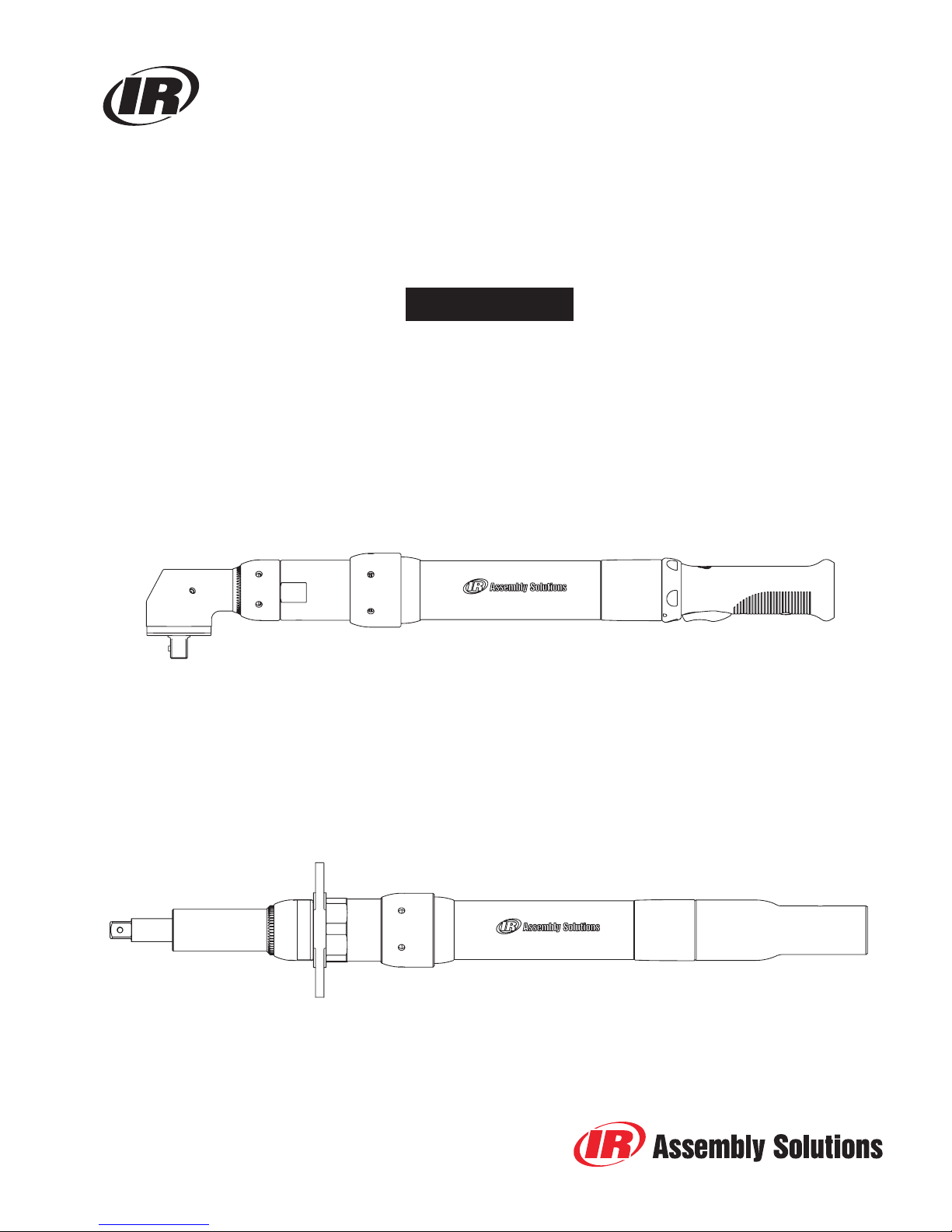
Service Manual for
QE8 Series High Torque
Angle Wrench and In-Line DC Electric Tools
NOTICE
For routine Maintenance, Operation and Instruction information regarding this product, see
Publication manual P7609, located at www.irtools.com/techdocuments, or contact the nearest
Ingersoll-Rand Office or Distributor.
Refer All Communications to the Nearest
Ingersoll-Rand Office or Distributor.
© Ingersoll-Rand Company 2004
Printed in U.S.A
(Dwg. TP2160a)
(Dwg. TP2160b)
1
Page 2
2
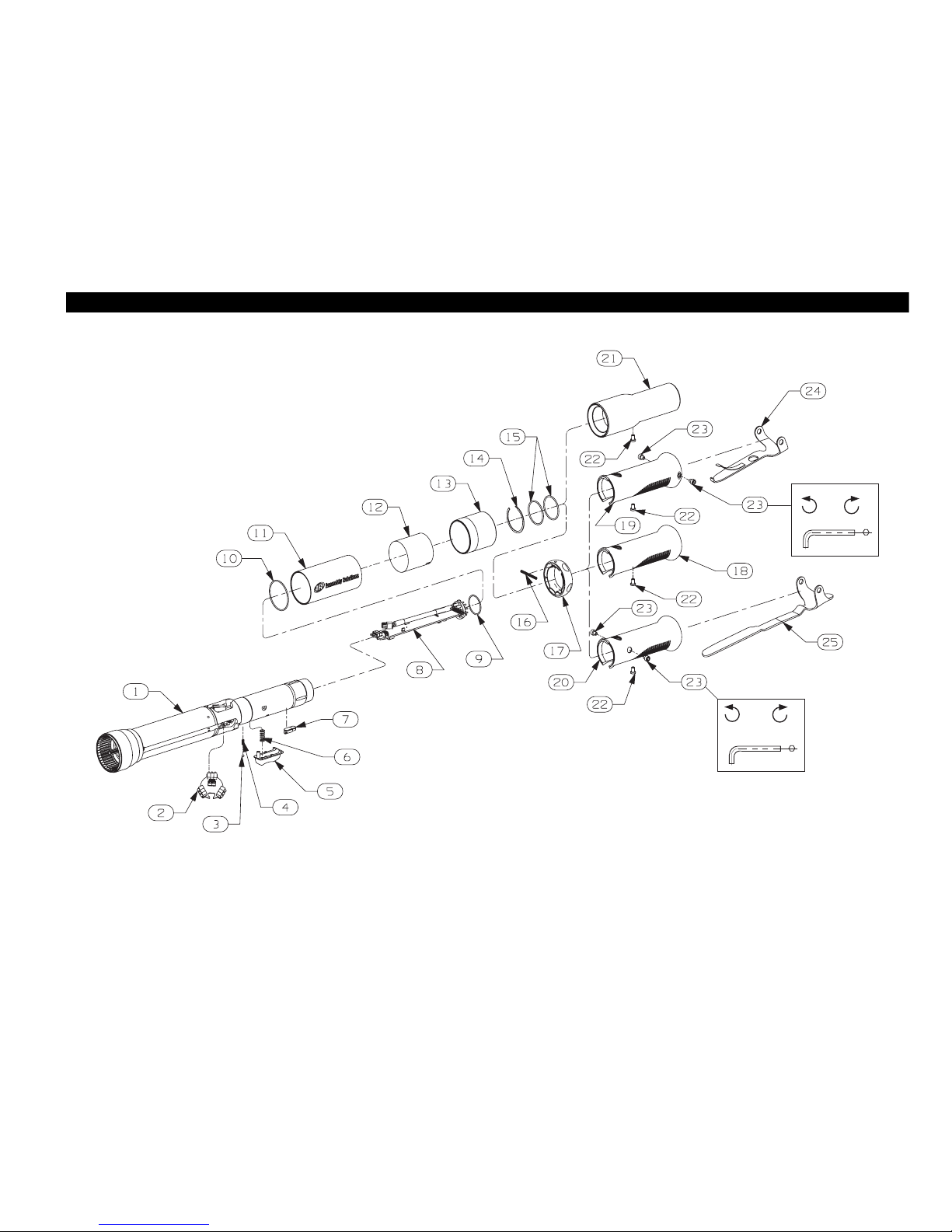
QE8 HIGH TORQUE MOTOR HOUSING ASSEMBLY, GRIPS AND LEVERS
(Dwg. TP2155)
OFF 1.1-1.7 Nm
OFF .05-1.1 Nm
5/64"
Page 3
3
\
QE8 HIGH TORQUE MOTOR HOUSING ASSEMBLY, GRIPS AND LEVERS
QE6 MOTOR HOUSING ASSEMBLY, GRIPS AND LEV
When Ordering, use applicable Part Number
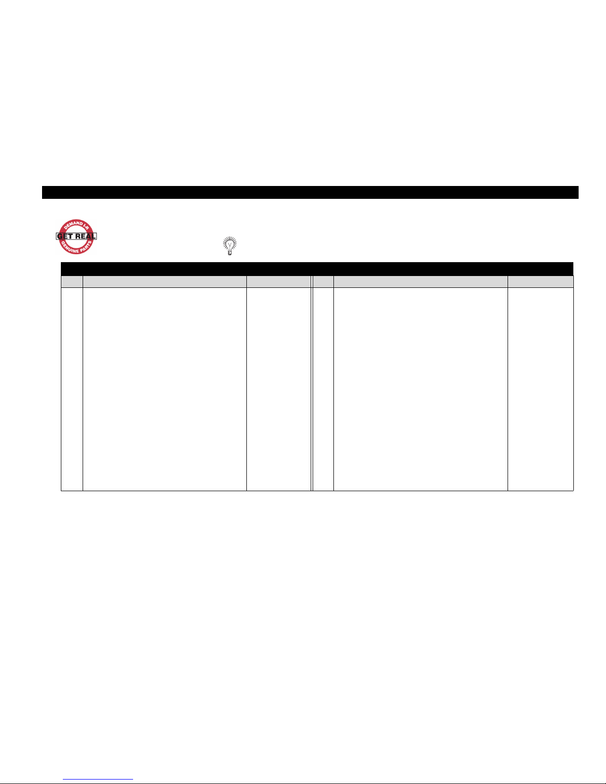
QE8 High Torque Motor Housing Assembly, Grips, and Levers Parts List
Item Part Description Part Number Item Part Description Part Number
1 Motor Housing Assembly 9 Retainer . . . . . . . . . . . . . . . . . . . . . . . . . . . . . . . . . . . . . . . GEA40-2309-104
FOR MODELS: 10 O-Ring . . . . . . . . . . . . . . . . . . . . . . . . . . . . . . . . . . . . . . . . . GEA40-136-211
QE8Z{ }070{ } { } . . . . . . . . . . . . . . . . . . . . . . . . . . GEA120-D53-491 11 Housing Cover . . . . . . . . . . . . . . . . . . . . . . . . . . . . . . . . . . GEA120-136
QE8Z{ }090{ } { } . . . . . . . . . . . . . . . . . . . . . . . . . GEA120-D53-491 12 Warning Label . . . . . . . . . . . . . . . . . . . . . . . . . . . . . . . . . . GEA40-99
FOR MODELS: 13 Label-Cover Lens . . . . . . . . . . . . . . . . . . . . . . . . . . . . . . . . GEA40-600
QE8A{ }225{ } { }. . . . . . . . . . . . . . . . . . . . . . . . . GEA240-D53-491 14 Retaining Ring . . . . . . . . . . . . . . . . . . . . . . . . . . . . . . . . . . GEA40-208
QE8S{ }150{ } { } . . . . . . . . . . . . . . . . . . . . . . . . . GEA240-D53-491 15 O-Ring . . . . . . . . . . . . . . . . . . . . . . . . . . . . . . . . . . . . . . . . GEA40-801
QE8Z{ }150{ } { } . . . . . . . . . . . . . . . . . . . . . . . . . . GEA240-D53-491 16 Spring . . . . . . . . . . . . . . . . . . . . . . . . . . . . . . . . . . . . . . . . . GEA40-329-52
FOR MODELS: 17 Reverse Ring . . . . . . . . . . . . . . . . . . . . . . . . . . . . . . . . . . . GEA40-329
QE8A{ }400{ } { }. . . . . . . . . . . . . . . . . . . . . . . . . # GEA400-D53-491 18 Handle Grip . . . . . . . . . . . . . . . . . . . . . . . . . . . . . . . . . . . . GEA40-135
QE8S{ }230{ } { } . . . . . . . . . . . . . . . . . . . . . . . . . . # GEA400-D53-491 19 Handle Grip . . . . . . . . . . . . . . . . . . . . . . . . . . . . . . . . . . . . GEA40-135SL
2 LED Board . . . . . . . . . . . . . . . . . . . . . . . . . . . . . . . . . . . GEA40-98 20 Handle Grip . . . . . . . . . . . . . . . . . . . . . . . . . . . . . . . . . . . . GEA40-135EL
3 Ball . . . . . . . . . . . . . . . . . . . . . . . . . . . . . . . . . . . . . . . . . AV1-255 21 Sleeve . . . . . . . . . . . . . . . . . . . . . . . . . . . . . . . . . . . . . . . . . GEA40-137
4 Spring . . . . . . . . . . . . . . . . . . . . . . . . . . . . . . . . . . . . . . GEA40-329-51 22 Socket Cap Screw (Low Head) . . . . . . . . . . . . . . . . . . . . . GEA40-135-68
5 Trigger . . . . . . . . . . . . . . . . . . . . . . . . . . . . . . . . . . . . . GEA40-273 23 Socket Head Cap Screw . . . . . . . . . . . . . . . . . . . . . . . . . . . GEA40-273EL-68
6 Spring . . . . . . . . . . . . . . . . . . . . . . . . . . . . . . . . . . . . . . GEA40-273-51 24 Lever, Short . . . . . . . . . . . . . . . . . . . . . . . . . . . . . . . . . . . . GEA40-273SL
7 Memory chip . . . . . . . . . . . . . . . . . . . . . . . . . . . . . . . . TRP-A528 25 Lever, Extended . . . . . . . . . . . . . . . . . . . . . . . . . . . . . . . . . GEA40-273EL
8 Communication Board . . . . . . . . . . . . . . . . . . . . . . . . . . GEA40-A2309
# Also includes GEF400-491-104
Page 4
4
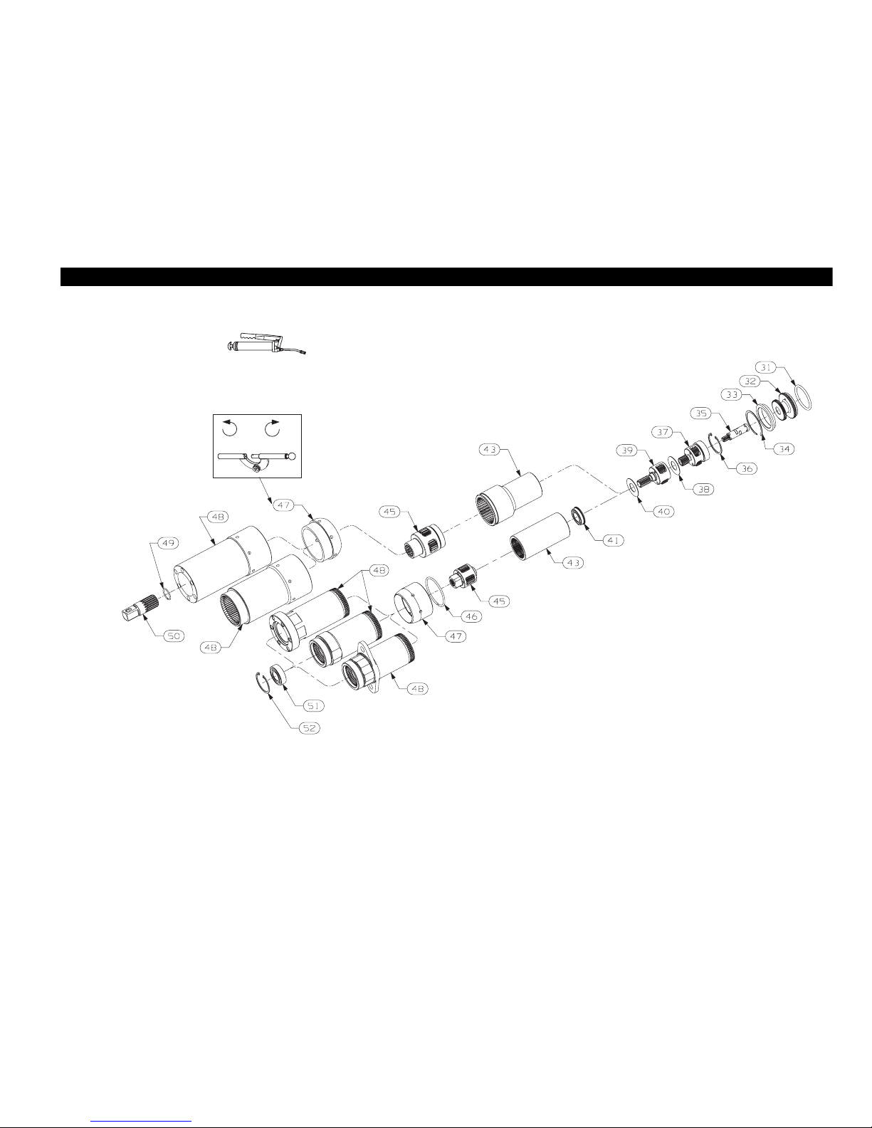
QE8 HIGH TORQUE GEARING COMPONENTS
(Dwg. TP2160_B)
Ingersoll-rand #67
OFF 68-81 Nm
Page 5
5
QE8 HIGH TORQUE GEARING COMPONENTS
When Ordering, use applicable Part Number
QE8 HIGH TORQUE GEARING PARTS LIST (Continued)
QE6 MOTOR HOUSING ASSEMBLY, GRIPS AND LEV
QE8 High Torque Gearing Parts List
ANGLE
--- --- --- QE8A{ }225{ }{ }
IN LINE
--- --- --- QE8S{ }150{ }{ }
OFFSET
QE8Z{ }070{ }{ } QE8Z{ }090{ }{ } QE8Z{ }150{ }{ } ---
Item Part Description Part Number Part Number Part Number Part Number
31 O-ring (I.D. 1.563 X .139) . . . . . . . . . . . . . . . . . . . . . . . . . . . --- --- --- ---
32 Transducer Assembly . . . . . . . . . . . . . . . . . . . . . . . . . . . . . . . GEA120-A756-90 GEA120-A756-90 GEA240-A756-160 GEA240-A756-160
33 Spacer . . . . . . . . . . . . . . . . . . . . . . . . . . . . . . . . . . . . . . . . . . . DEA120-945 DEA120-945 GEA240-945 GEA240-945
* Gear Case Assembly . . . . . . . . . . . . . . . . . . . . . . . . . . . . . . . . GEP120-M37 GEP150-M37 GEP240-M37 GEA240-M37
34 Retainer . . . . . . . . . . . . . . . . . . . . . . . . . . . . . . . . . . . . . DEA120-29 DEA120-29 GEA240-208 GEA240-208
35 Pinion Coupler Assembly . . . . . . . . . . . . . . . . . . . . . . DEA120-17 DEA120-17 DEA120-17 DEA120-17
36 Retaining Ring . . . . . . . . . . . . . . . . . . . . . . . . . . . . . . . W64-118 W64-118 W64-118 W64-118
37 Spindle Assembly (1st Stage) . . . . . . . . . . . . . . . . . . . DEA120-A216 DEA150-A216 DEA55-A216 DEA55-A216
Spindle . . . . . . . . . . . . . . . . . . . . . . . . . . . . . . . . . . --- --- --- ---
Planet Pin . . . . . . . . . . . . . . . . . . . . . . . . . . . . . . . . --- --- --- ---
Planet Bearing . . . . . . . . . . . . . . . . . . . . . . . . . . . . . --- --- --- ---
Planet Gear (1st) . . . . . . . . . . . . . . . . . . . . . . . . . . . --- --- --- ---
Bearing . . . . . . . . . . . . . . . . . . . . . . . . . . . . . . . . . .
38 Spacer . . . . . . . . . . . . . . . . . . . . . . . . . . . . . . . . . . . . . . --- --- GEA240-80 GEA240-80
39 Spindle Assembly (2nd Stage) . . . . . . . . . . . . . . . . . . . DEA120-A8 DEA150-A8 GEA240-A216 GEA240-A216
Spindle . . . . . . . . . . . . . . . . . . . . . . . . . . . . . . . . . . --- --- --- ---
Planet Pin . . . . . . . . . . . . . . . . . . . . . . . . . . . . . . . . --- --- --- ---
Planet Bearing . . . . . . . . . . . . . . . . . . . . . . . . . . . . . --- --- --- ---
Planet Gear (2nd) . . . . . . . . . . . . . . . . . . . . . . . . . . . --- --- --- ---
40 Spacer . . . . . . . . . . . . . . . . . . . . . . . . . . . . . . . . . . . . . . --- --- GEA240-80 GEA240-80
41 Bearing . . . . . . . . . . . . . . . . . . . . . . . . . . . . . . . . . . . . . --- --- GEA240-606 GEA240-606
43 Ring Gear . . . . . . . . . . . . . . . . . . . . . . . . . . . . . . . . . . . DEA120-406 DEA200-406 GEA240-406 GEA240-406
Page 6
6
QE8 HIGH TORQUE GEARING COMPONENTS (Continued)
When Ordering, use applicable Part Number
QE8 High Torque Gearing Parts List
ANGLE
--- --- --- QE8A{ }225{ }{ }
IN LINE
--- --- --- QE8S{ }150{ }{ }
OFFSET
QE8Z{ }070{ }{ } QE8Z{ }090{ }{ } QE8Z{ }160{ }{ } ---
Item Part Description Part Number Part Number Part Number Part Number
45
Spindle Assembly (3rd Stage) . . . . . . . . . . . . . . . . . . . --- ---
GEA240-A8 GEA240-A8
Spindle . . . . . . . . . . . . . . . . . . . . . . . . . . . . . . . . . . .
--- --- --- ---
Planet Pin . . . . . . . . . . . . . . . . . . . . . . . . . . . . . . . . .
--- --- --- ---
Needle Rollers . . . . . . . . . . . . . . . . . . . . . . . . . . . . . .
--- --- --- ---
Spacer . . . . . . . . . . . . . . . . . . . . . . . . . . . . . . . . . . . .
--- --- --- ---
Planet Gear (3rd) . . . . . . . . . . . . . . . . . . . . . . . . . . . .
--- --- --- ---
46
Retainer . . . . . . . . . . . . . . . . . . . . . . . . . . . . . . . . . . . .
DEF120-29 DEF120-29 GEF240-29 GEF240-29
47
Coupling Nut . . . . . . . . . . . . . . . . . . . . . . . . . . . . . . . . GEF120-43 GEF120-43
GEA240-43 GEA240-43
48
Gear Case . . . . . . . . . . . . . . . . . . . . . . . . . . . . . . . . . . .
GEP120-B37 GEP120-B37 GEP240-B37 GEA240-B37
49
Retaining Ring . . . . . . . . . . . . . . . . . . . . . . . . . . . . . . . --- --- --- ---
50
Spindle . . . . . . . . . . . . . . . . . . . . . . . . . . . . . . . . . . . . . --- --- --- ---
51
Bearing . . . . . . . . . . . . . . . . . . . . . . . . . . . . . . . . . . . . R38P-606 R38P-606 --- ---
52
Retaining Ring . . . . . . . . . . . . . . . . . . . . . . . . . . . . . . . W64-118 W64-118 --- ---
REFER ALSO TO THESE MANUALS
P7781 P7781 P7781
---
Page 7
7
QE8 HIGH TORQUE GEARING COMPONENTS (Continued)
When Ordering, use applicable Part Number
QE6 MOTOR HOUSING ASSEMBLY, GRIPS AND LEV
QE8 High Torque Gearing Parts List (Continued)
ANGLE
QE8A{ }225F{ } --- QE8A{ }400F{ }
IN LINE
QE8S{ }150F{ } QE8S{ }230F{ } ---
OFFSET
--- --- ---
Item Part Description Part Number Part Number Part Number
31 O-ring (I.D. 1.563 X .139) . . . . . . . . . . . . . . . . . . . . . . . . . . . . . . . . . . . . . . . --- GEF400-491-104 GEF400-491-104
32 Transducer Assembly . . . . . . . . . . . . . . . . . . . . . . . . . . . . . . . . . . . . . . . . . . . GEA240-A756-160 GEF400-A756-230 GEF400-A756-230
33 Spacer . . . . . . . . . . . . . . . . . . . . . . . . . . . . . . . . . . . . . . . . . . . . . . . . . . . . . . . GEA240-945 N/A N/A
* Gear Case Assembly . . . . . . . . . . . . . . . . . . . . . . . . . . . . . . . . . . . . . . . . . . . . GEF240-M37 GEP400-M37 GEF400-M37
34 Retainer . . . . . . . . . . . . . . . . . . . . . . . . . . . . . . . . . . . . . . . . . . . . . . . . . . GEA240-208 N/A N/A
35 Pinion Coupler Assembly . . . . . . . . . . . . . . . . . . . . . . . . . . . . . . . . . . . . DEA120-17 GEF400-17 GEF400-17
36 Retaining Ring . . . . . . . . . . . . . . . . . . . . . . . . . . . . . . . . . . . . . . . . . . . . . W64-118 W64-118 W64-118
37 Spindle Assembly (1st Stage) . . . . . . . . . . . . . . . . . . . . . . . . . . . . . . . . . DEA55-A216 DEA90-A216 DEA90-A216
Spindle . . . . . . . . . . . . . . . . . . . . . . . . . . . . . . . . . . . . . . . . . . . . . . . . --- --- ---
Planet Pin . . . . . . . . . . . . . . . . . . . . . . . . . . . . . . . . . . . . . . . . . . . . . . --- --- ---
Planet Bearing . . . . . . . . . . . . . . . . . . . . . . . . . . . . . . . . . . . . . . . . . . --- --- ---
Planet Gear (1st) . . . . . . . . . . . . . . . . . . . . . . . . . . . . . . . . . . . . . . . . . --- --- ---
Bearing . . . . . . . . . . . . . . . . . . . . . . . . . . . . . . . . . . . . . . . . . . . . . . . . --- --- ---
38 Spacer . . . . . . . . . . . . . . . . . . . . . . . . . . . . . . . . . . . . . . . . . . . . . . . . . . . GEA240-80 GEF400-80 GEF400-80
39 Spindle Assembly (2nd Stage) . . . . . . . . . . . . . . . . . . . . . . . . . . . . . . . . GEA240-A216 GEF400-A216 GEF400-A216
Spindle . . . . . . . . . . . . . . . . . . . . . . . . . . . . . . . . . . . . . . . . . . . . . . . . --- --- ---
Planet Pin . . . . . . . . . . . . . . . . . . . . . . . . . . . . . . . . . . . . . . . . . . . . . . --- --- ---
Planet Bearing . . . . . . . . . . . . . . . . . . . . . . . . . . . . . . . . . . . . . . . . . . --- --- ---
Planet Gear (2nd) . . . . . . . . . . . . . . . . . . . . . . . . . . . . . . . . . . . . . . . . --- --- ---
40 Spacer . . . . . . . . . . . . . . . . . . . . . . . . . . . . . . . . . . . . . . . . . . . . . . . . . . . GEA240-80 GEF400-80 GEF400-80
41 Bearing . . . . . . . . . . . . . . . . . . . . . . . . . . . . . . . . . . . . . . . . . . . . . . . . . . GEA240-606 --- ---
43 Ring Gear . . . . . . . . . . . . . . . . . . . . . . . . . . . . . . . . . . . . . . . . . . . . . . . . GEA240-406 GEF400-406 GEF400-406
Page 8
8
QE8 HIGH TORQUE GEARING PARTS LIST (Continued)
When Ordering, use applicable Part Number
QE8 High Torque Gearing Parts List (Continued)
ANGLE
QE8A{ }225F{ } --- QE8A{ }400F{ }
IN LINE
QE8S{ }150F{ } QE8S{ }230F{ } ---
OFFSET
--- --- ---
Item Part Description Part Number Part Number Part Number
45 Spindle Assembly (3rd Stage) . . . . . . . . . . . . . . . . . . . . . . . . . . . . . . . . . GEA240-A8 GEF400-A8 GEF400-A8
Spindle . . . . . . . . . . . . . . . . . . . . . . . . . . . . . . . . . . . . . . . . . . . . . . . . --- --- ---
Planet Pin . . . . . . . . . . . . . . . . . . . . . . . . . . . . . . . . . . . . . . . . . . . . . . --- --- ---
Needle Rollers . . . . . . . . . . . . . . . . . . . . . . . . . . . . . . . . . . . . . . . . . . --- --- ---
Spacer . . . . . . . . . . . . . . . . . . . . . . . . . . . . . . . . . . . . . . . . . . . . . . . . . --- --- ---
Planet Gear (3rd) . . . . . . . . . . . . . . . . . . . . . . . . . . . . . . . . . . . . . . . . --- --- ---
46 Retainer . . . . . . . . . . . . . . . . . . . . . . . . . . . . . . . . . . . . . . . . . . . . . . . . . . GEF240-29 N/A N/A
47 Coupling Nut . . . . . . . . . . . . . . . . . . . . . . . . . . . . . . . . . . . . . . . . . . . . . . GEA240-43 GEF400-43 GEF400-43
48 Gear Case . . . . . . . . . . . . . . . . . . . . . . . . . . . . . . . . . . . . . . . . . . . . . . . . GEF240-B37 GEP400-B37 GEF400-B37
49 Retaining Ring . . . . . . . . . . . . . . . . . . . . . . . . . . . . . . . . . . . . . . . . . . . . --- GEF400-29 ---
50 Spindle . . . . . . . . . . . . . . . . . . . . . . . . . . . . . . . . . . . . . . . . . . . . . . . . . . . --- GEF400-584 ---
51 Bearing . . . . . . . . . . . . . . . . . . . . . . . . . . . . . . . . . . . . . . . . . . . . . . . . . . --- ---
52 Retaining Ring . . . . . . . . . . . . . . . . . . . . . . . . . . . . . . . . . . . . . . . . . . . . --- ---
Page 9

9
This Page intentionally left Blank
Page 10
10
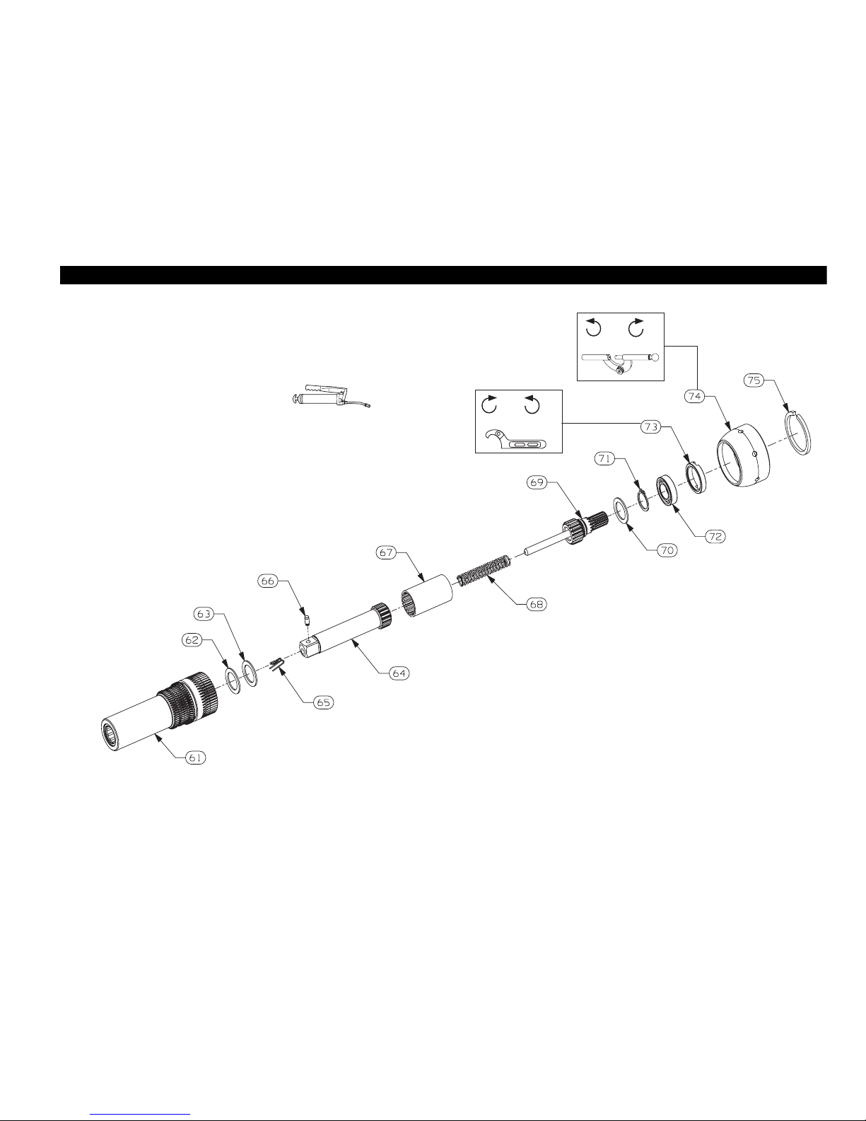
QE8 HIGH TORQUE IN-LINE ATTACHMENT COMPONENTS
(Dwg. TP2293)
OFF 61-68 Nm
OFF 61-68 Nm
Ingersoll-Rand #
67
Page 11
11
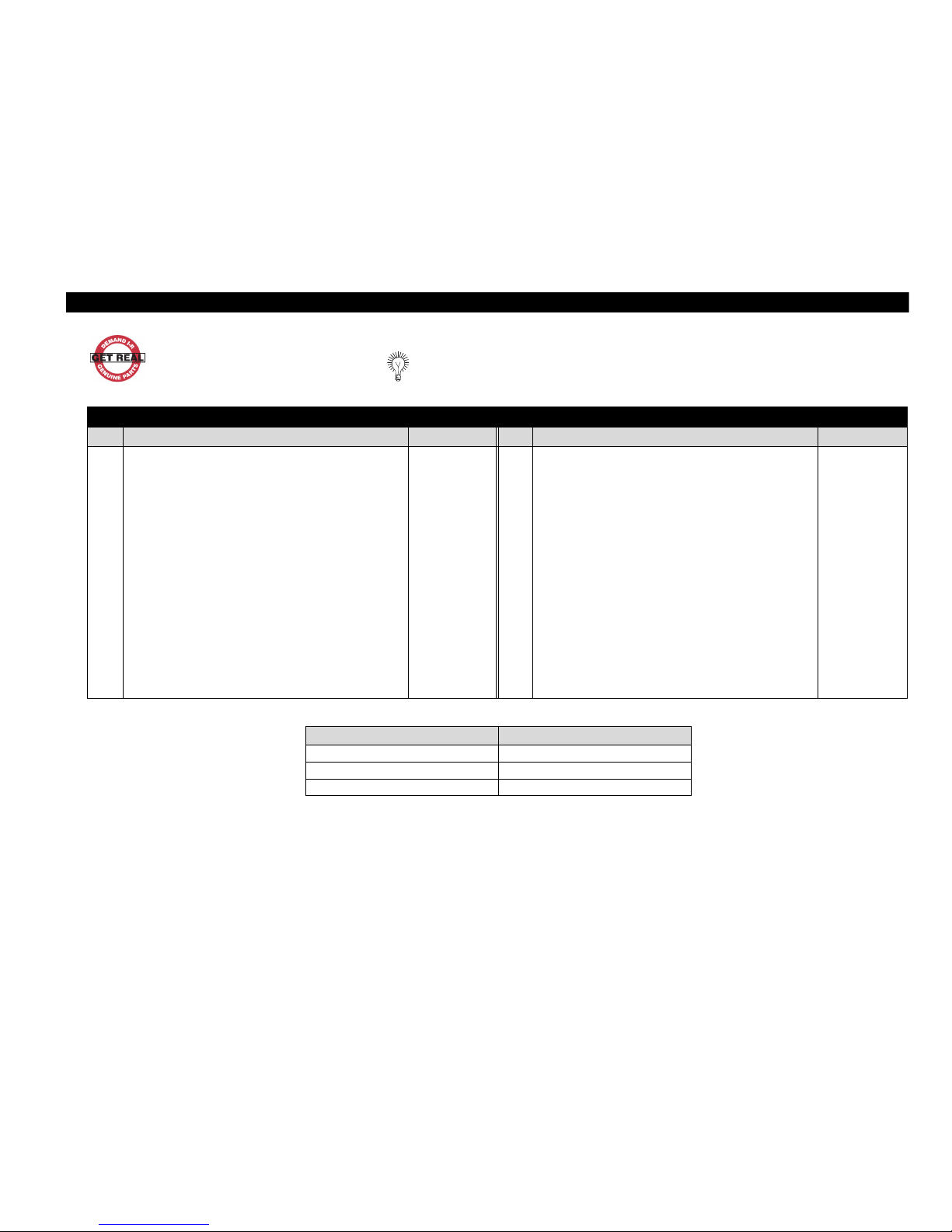
QE8 HIGH TORQUE IN-LINE ATTACHMENT COMPONENTS
When Ordering, use applicable Part Number
QE8 In-line Spindles Parts List
Item Part Description Part Number Item Part Description Part Number
z In-Line Spindle Assemblies --- 66 Socket Retaining Pin . . . . . . . . . . . . . . . . . . . . . . . . . . . . . . . 804-716
--- QE8S{ }150{ }41S08 (1/2" Sq. Drive & 4" Long Shank) 160E4S8 67 Coupler . . . . . . . . . . . . . . . . . . . . . . . . . . . . . . . . . . . . . . . . . ---
--- QE8S{ }150{ }61S08 (1/2" Sq. Drive & 6" Long Shank) 160E6S8 --- for 41S08 . . . . . . . . . . . . . . . . . . . . . . . . . . . . . . . . . . . . 120E4-581
--- QE8S{ }150{ }81S08 (1/2" Sq. Drive & 8" Long Shank) 160E8S8 --- for 61S08, and 81S08 . . . . . . . . . . . . . . . . . . . . . . . . . . 120E6-581
61 Housing Assembly --- 68 Disengaging Spring . . . . . . . . . . . . . . . . . . . . . . . . . . . . . . . . ---
--- for 41S08 . . . . . . . . . . . . . . . . . . . . . . . . . . . . . . . . . . . . 160E4-A580 --- for 41S08 . . . . . . . . . . . . . . . . . . . . . . . . . . . . . . . . . . . . 120E4-626
--- for 61S08 . . . . . . . . . . . . . . . . . . . . . . . . . . . . . . . . . . . . 160E6-A580 --- for 61S08, and 81S08 . . . . . . . . . . . . . . . . . . . . . . . . . . 120E6-626
--- for 81S08 . . . . . . . . . . . . . . . . . . . . . . . . . . . . . . . . . . . . 160E8-A580 69 Drive Spindle Assembly . . . . . . . . . . . . . . . . . . . . . . . . . . . . 160E4-A584
62 Washer . . . . . . . . . . . . . . . . . . . . . . . . . . . . . . . . . . . . . . . . . . 120E4-105 70 Washer . . . . . . . . . . . . . . . . . . . . . . . . . . . . . . . . . . . . . . . . . . 120E4-106
63 Washer . . . . . . . . . . . . . . . . . . . . . . . . . . . . . . . . . . . . . . . . . . 120E4-106 71 Retaining Ring . . . . . . . . . . . . . . . . . . . . . . . . . . . . . . . . . . . . FEA100-20
64 Square Drive Spindle --- 72 Rear Spindle Bearing . . . . . . . . . . . . . . . . . . . . . . . . . . . . . . . GEA240-593
--- for 41S08 . . . . . . . . . . . . . . . . . . . . . . . . . . . . . . . . . . . . 120E4S8-586 73 Bearing Cap . . . . . . . . . . . . . . . . . . . . . . . . . . . . . . . . . . . . . . 8SA32-531
--- for 61S08 . . . . . . . . . . . . . . . . . . . . . . . . . . . . . . . . . . . . 120E6S8-586 74 Coupling Nut . . . . . . . . . . . . . . . . . . . . . . . . . . . . . . . . . . . . . GEA240-27
--- for 81S08 . . . . . . . . . . . . . . . . . . . . . . . . . . . . . . . . . . . . 120E8S8-586 75 Retainer . . . . . . . . . . . . . . . . . . . . . . . . . . . . . . . . . . . . . . . . . 160E4-29
65 Socket Retainer Spring . . . . . . . . . . . . . . . . . . . . . . . . . . . . . . 5UHD-718
FOR MODEL REFER TO THESE MANUALS
QE8Z{ }070{ }{ }, QE8Z{ }090{ }{ } P7778
QE8Z{ }150{ }{ } P7778
QE8S{ }230{ }{ } P7777
Page 12
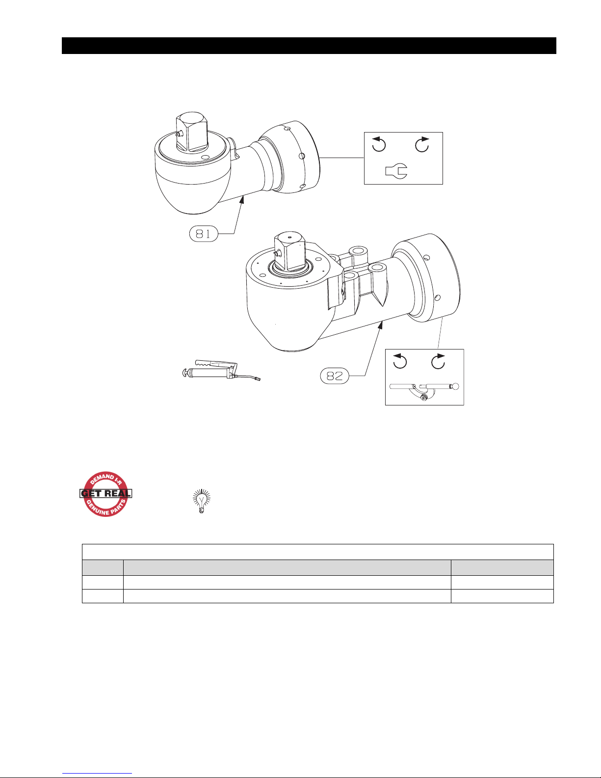
QE8 ANGLE HEAD ATTACHMENTS
OFF 61-68 Nm
OFF 61-68 Nm
HUSKEY HTS-2
(Dwg. TP2294)
When Ordering, use applicable Part Number
QE8 Angle Head Attachments Parts List
Item Product Identification Code Part Number
81 QE8A{ }225{ }A7S12 AA16S12
82 QE8A{ }400{ }A8S12 AA20S12
12
Page 13
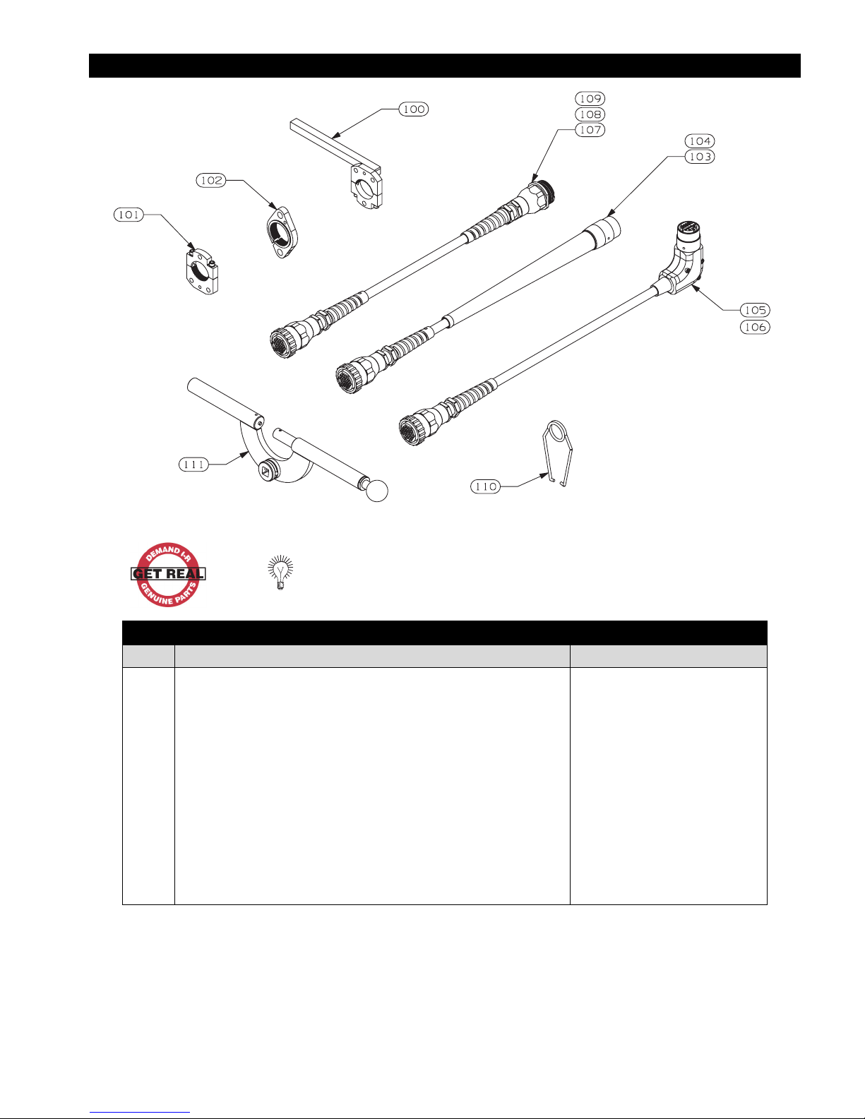
QE8 HIGH TORQUE ACCESSORIES
When Ordering, use applicable Part Number
QE8 High Torque Accessories Parts List
Item Part Description Part Number
100 †
101 †
102 †
103
104
105
106
107
108
109
110
111
† FOR MODEL QE8{ }150{ }{ } NON-FLANGED MODELS ONLY
Reaction Bar Assembly . . . . . . . . . . . . . . . . . . . . . . . . . . . . . . . . . . . . .
Mounting Plate Assembly . . . . . . . . . . . . . . . . . . . . . . . . . . . . . . . . . . . .
Mounting Plate Assembly (Flanged) . . . . . . . . . . . . . . . . . . . . . . . . . . . . GEM120-K48
Power Cord Assembly
Power Cord Assembly
Power Cord Assembly, 90 Deg.
Power Cord Assembly, 90 Deg.
Power Cord Extension Assembly
Power Cord Extension Assembly
Power Cord Extension Assembly
Suspension Bail . . . . . . . . . . . . . . . . . . . . . . . . . . . . . . . . . . . . . . . . . . . . .
Spanner Wrench . . . . . . . . . . . . . . . . . . . . . . . . . . . . . . . . . . . . . . . . . . . .
(3 Meter)
(10 Meter)
(3 Meter)
(10 Meter)
. . . . . . . . . . . . . . . . . . . . . . . . . . . . . . .
. . . . . . . . . . . . . . . . . . . . . . . . . . . . . .
. . . . . . . . . . . . . . . . . . . . . . . .
. . . . . . . . . . . . . . . . . . . . . . .
(10 Meter)
(20 Meter)
(40 Meter)
. . . . . . . . . . . . . . . . . . . . . .
. . . . . . . . . . . . . . . . . . . . . .
. . . . . . . . . . . . . . . . . . . . . .
DEA120-K48
DAM120-K48
GEA40-C0RD-3M
GEA40-C0RD-10M
GEA40-C0RD-3M-90
GEA40-C0RD-10M-90
GEA40-EXT-10M
GEA40-EXT-20M
GEA40-EXT-40M
7L-365
GEA40-478
(Dwg. TP2292)
13
Page 14
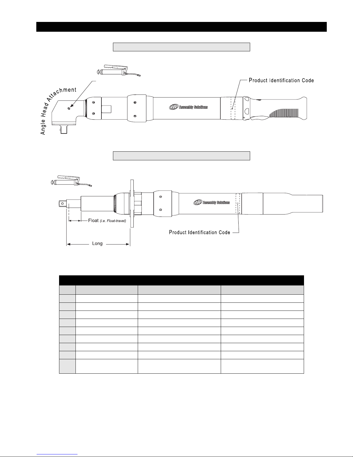
QE8 TOOL ASSEMBLIES
Angles
Ingersoll-Rand #
HUSKEY HTS-2
67
(Dwg. TP2161b)
In-Lines
Table 1
Suggested Tools Parts List
Item Tool Used Description Where Used?
1
Spanner Wrench I-R Part #GEA40-478 Coupling Nut
2
Pin Spanner Wrench 3 mm or 1/8” pin Motor Housing Assembly, Cable
3
Torque Wrench 1/2” Sq. Drive, 50 ft-lb capacity General use
4
Adjustable Pin Wrench ----- In-Lines, Bearing Caps
5
Adjustable Wrench ----- Coupling Nut (with flats)
6
5/64” Hex Key ----- Cap Screws (Low Socket Head)
7
9/64” Hex Key ----- Cap Screws (Regular Head)
8
Internal Snap Ring Pliers ----- General use
9
Pick -----
O-Rings (behind Reverse Ring),
Smalley Ring, etc.
(Dwg. TP2161a)
14
Page 15
MAINTENANCE
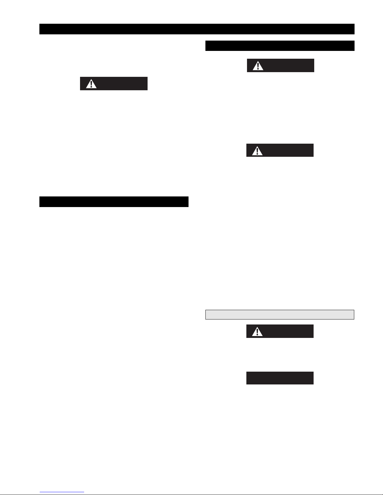
General Instructions:
• Refer to Table 1 “Suggested Tools Parts List” for
quick reference to the tools recommended for the
following disassembly/assembly instructions.
WARNING
• Repairs should be made only by authorized trained
personnel. Consult your nearest Ingersoll-Rand
Authorized Service Center.
• Disconnect the power cord from the receptacle
before performing any maintenance on this or any
other tool.
• Always use protective eyewear when performing
maintenance on a tool or while operating a tool.
• Use of non-Ingersoll-Rand parts or failure to follow
Maintenance Instructions may create a risk of
electric shock or injury.
LUBRICATION
Whenever this product is disassembled, clean the parts and
re-lubricate them as follows:
1. Using appropriate tool, loosen the Attachment
Coupling Nut (74).
2. Unthread Coupling Nut from Gear Case Assembly and
remove Attachment.
3. Using appropriate tool, loosen the Gear Case Coupling
Nut (47).
4. Unthread Coupling Nut and remove Gear Case
Assembly.
5. Disassemble Gear Case.
6. Clean and degrease all parts except for the bearings, 1
nd
Stage Spindle Assembly (37), 2
Assembly (39) and the 3
(45).
7. Wipe clean the Spindle Assemblies with a clean, dry
and lint-free rag.
8. Once cleaned, apply prescribed amounts of
Ingersoll-Rand #67 Grease as follows:
rd
Stage Spindle
stage Spindle Assembly
DISASSEMBLY
WARNING
•This procedure is to be performed by an authorized, trained repair person. To ensure proper
functioning of the tool:
• When replacing the Motor Housing Assembly (1),
always ensure that the Memory Chip (7),
Communication Board (8), Gear Case Assembly,
and Attachment are all assembled as a set with the
new Motor Housing Assembly.
CAUTION
• When replacing an Attachment, always use the
Angle Head Attachment designed for that model.
Never replace an Angle Head Attachment with an
In-Line Attachment.
• When replacing a Gear Case Assembly, always use
the Assembly designed for that model.
General Instructions for Disassembly:
1. Do not disassemble the tool any further than necessary
to replace or repair damaged parts.
2. To protect part surfaces and to prevent distortion of
Housings and threaded joints, use care when grasping
the tool.
3. Avoid clamping non-metal surfaces, unless directed
otherwise.
4. Do not remove any press fit part or any part of an
assembly unless its removal is necessary for repair or
replacement.
st
Attachments
WARNING
• NEVER grasp the tool in a vise, as this will likely
result in damage to the tool causing wire leads to
malfunction, which increases the risk of electric
shock.
• 3 - 4 cc to central area between gears of each
Spindle Assembly (37, 39 & 45).
• Thin layer on Ring Gear teeth (43)
9. For Models with an Angle Head Attachment:
Using HUSKY HTS-2 Grease, lubricate Angle Head
(81 or 82) through Grease Fitting.
10. For Models with an In-Line Attachment:
Using Ingersoll-Rand #67 Grease, lubricate the Square
Drive Spindle Bearings, the Drive Spindle (64) and the
Disengaging Spring (68).
CAUTION
• When installing or removing a Coupling Nut,
ALWAYS hold the tool by the Spanner holes or
flats as provided on the Assembly Housing.
15
Page 16

MAINTENANCE (Continued)
Attachment Removal
FOR MODELS:
QE8A{ }225{ }{ }
QE8A{ }400{ }{ }
QE8S{ }150{ }{ }
1. Using Spanner Wrench #GEA40-478 (or other
appropriate wrench), grasp the Spanner holes of the
Coupling Nut (74).
2. Holding firmly onto tool with the wrench flats (or
Spanner holes) of the Gear Case (48), unscrew
Coupling Nut and pull the Attachment out of the Gear
Case.
FOR ALL OTHER MODELS:
1. Remove screws around the flange of the Attachment
while supporting both ends of the tool.
2. Pull Attachment from the Mounting plate and Gear
Case or Offset Gear Case.
3. Pull remainder of the Tool from mounting plate.
Angle Head Attachments - Disassembly
DISASSEMBLY OF ANGLE HEAD ATTACHMENTS
IS NOT RECOMMENDED.
Spindle Bearing (72) off the Drive Spindle Assembly
(69). Then remove the Retaining Ring (71), and
Washer (70).
9. Now tilt Spindle Housing, causing the Disengaging
Spring (68), Coupler (67), Square Drive Spindle (64),
and Washers (62) and (63) to slide out.
FOR ALL OTHER SPINDLES:
REFER TO THE APPROPRIATE MAINTENANCE
MANUAL LISTED IN THE QE8 HIGH TORQUE
IN-LINE SPINDLE PARTS LIST.
Motor Housing Disassembly
Gear Case Removal
FOR ALL MODELS:
1. Carefully engage spanner holes on the Gear Case
Coupling Nut (47) with the appropriate tool and loosen
the Coupling Nut while gripping the wrench flats of the
Gear Case (48) with the appropriate wrench.
2. Unthread the Coupling Nut and pull the Gear Case
Assembly off the Motor Housing Assembly.
FOR MODELS WITH OFFSET GEAR CASES:
QE8Z{ }070{ }{ }
QE8Z{ }090{ }{ }
QE8Z{ }150{ }{ }
In-Line Attachments - Disassembly
FOR 160E4S8, 160E6S8 & 160E8S8 IN-LINE
ATTACHMENTS.
1. Looking down the hole of the Square Drive Spindle's
(64) square socket, locate Retaining Pin (66) and
Retaining Spring (65).
2. If necessary, use a pointed metal probe to pull retaining
Spring out of Spindle cavity.
3. Also if necessary, remove Pin from Square Drive
Spindle (64).
4. Using Spanner Wrench #GEA40-478 (or other appropriate wrench), grasp the Spanner holes (or flats) of the
Coupling Nut (74).
5. If desired, remove Coupling Nut Retainer (75) using
the appropriate tool.
Note: In the following step, the Bearing Cap (73) has a
left-hand thread.
6. Using an adjustable Pin Wrench, unscrew Bearing Cap
(73).
7. Pull the Drive Spindle Assembly (69) out of Housing
Assembly (61).
8. If necessary, using a bearing puller tool, press the Rear
1. Remove the screws around the flange of the Offset
Gearing that attach it to the Gear Case assembly with
the appropriate wrench while gripping the wrench flats
of the Tool Gear Case with the appropriate wrench.
2. Pull Offset Gearing from the Gear Case.
16
Page 17

MAINTENANCE (Continued)
Gear Case - Disassembly
FOR GEP120-M37 AND GEP150-M37
1. Remove the Pinion Coupler Assembly (35) from the
Motor Housing Assembly.
2. If the Coupling Nut requires replacement, spread the
ends of the Retaining Ring (46) and remove it from the
Gear Case Assembly. Slide Coupling Nut off the Gear
Case Assembly.
3. Work a pointed tool under the Ring Gear Retainer (34)
and spiral it out of the Gear Case (48).
4. Tilt the Gear Case Assembly so that the Ring Gear (43)
st
and 1
Stage Spindle Assembly (37) slide out of the
Gear Case Assembly.
5. With the motor end of the Gear Case Assembly
standing on the table of an Arbor press, carefully press
nd
the 2
Stage Spindle Assembly (39) out of the Bearing
(51) while lightly supporting the Spindle Assembly
from beneath to avoid breakage.
6. Using internal snap ring pliers, remove the Retaining
Ring (52) from the threaded end of the Gear Case (48).
7. Remove Bearing (51) from the Gear Case.
FOR GEF400-M37 AND GEP400-M37
1. Remove the Pinion Coupler Assembly (35) from the
Motor Housing Assembly.
2. If the Coupling Nut requires replacement, slide the
Coupling Nut off the Motor Housing Assembly.
3. From the output end of the Gear Case Assembly, push
rd
the 3
Stage Spindle Assembly (45) until the Ring
st
Gear, 1
dle Assembly (39) and 3
Stage Spindle Assembly (37), 2nd Stage Spin-
rd
Stage Spindle Assembly
(45) slide out of the Gear Case (48) all together.
4. Using internal snap ring pliers, remove the Retaining
Ring (36) from the Ring Gear.
5. Tilt the ring gear and slide the 1
nd
Assembly (37) and 2
Stage Spindle Assembly (39)
st
Stage Spindle
out of the Ring Gear.
6. From the output end of the Ring Gear, carefully pull
rd
the 3
Stage Spindle Assembly (45) out of the ring
gear. It may be necessary to push it from the opposite
side.
7. If necessary, remove the O-ring (31), from the Motor
Housing Assembly.
FOR GEA240-M37, GEF240-M37 AND GEP240-M37
1. Remove the Pinion Coupler Assembly (35) from the
Motor Housing Assembly
2. Work a pointed tool under the Ring Gear Retainer (34)
and spiral it out of the Gear Case (48).
3. Tilt the Gear Case Assembly so that the Ring Gear
st
(43), 1
dle Assembly (39) and 3
Stage Spindle Assembly (37), 2nd Stage Spin-
rd
stage Spindle Assembly
(45) slide out of the Gear Case (48) all together.
4. Using internal snap ring pliers, remove the Retaining
Ring (36) from the Ring Gear.
5. Tilt the ring gear and slide the 1
nd
Assembly (37) and 2
Stage Spindle Assembly (39)
st
Stage Spindle
out of the Ring Gear.
6. With the output end of the Ring Gear resting on the
table of an arbor press, carefully press the 3
rd
Stage
Spindle Assembly (45) from the Spindle Bearing (41)
and out of the Ring Gear.
7. From the output end of the Ring Gear, push the Spindle
bearing (41) out of the Ring Gear.
8. If the Coupling Nut requires replacement, spread the
ends of the Retaining Ring (46) and remove it from the
Gear Case Assembly.
FOR OFFSET GEARING DISASSEMBLY:
REFER TO THE APPROPRIATE MAINTENANCE
MANUAL LISTED IN THE QE8 HIGH TORQUE
GEARING PARTS LIST.
WARNING
• This procedure is to be done by an authorized, trained
repair person. To ensure proper functioning of the
tool:
When replacing the Motor Housing Assembly (1), always
ensure that the Memory Chip (7), Communication Board
(8), Gear Case Assembly, and Attachment are all assembled
as a set with the new Motor Housing Assembly.
Grips
1. For models with levers, use the appropriate hex key to
loosen Cap Screws (23) from lever (24 or 25) and
remove lever from Handle Grip (19 or 20).
2. Use the appropriate hex key to loosen the Cap Screw
(22) from Handle Grip (18, 19, 20 or 21).
3. Slide Handle Grip off of Motor House Assembly (1).
17
Page 18
MAINTENANCE (Continued)
Disassembly of External Components
1. Dislodge O-rings (15) and remove Memory Chip (7)
from assembly.
2. Remove Trigger mechanism (5) from Motor Housing
Assembly.
3. Remove Spring (6) from Trigger mechanism.
4. Slide Reverse Ring (17) away from Motor Housing
Assembly, being careful not to lose the Detent Ball (3)
or Springs (4) and (16).
5. Remove Retaining Ring (14) from behind Label Cover
Lens (13).
6. In a sliding motion, pull Warning Label (12) and Label
Cover Lens (13) off end of Motor Housing Assembly.
7. Slide Housing Cover (11) off Motor Housing
Assembly.
8. Remove O-ring (10) located at front of Housing Cover.
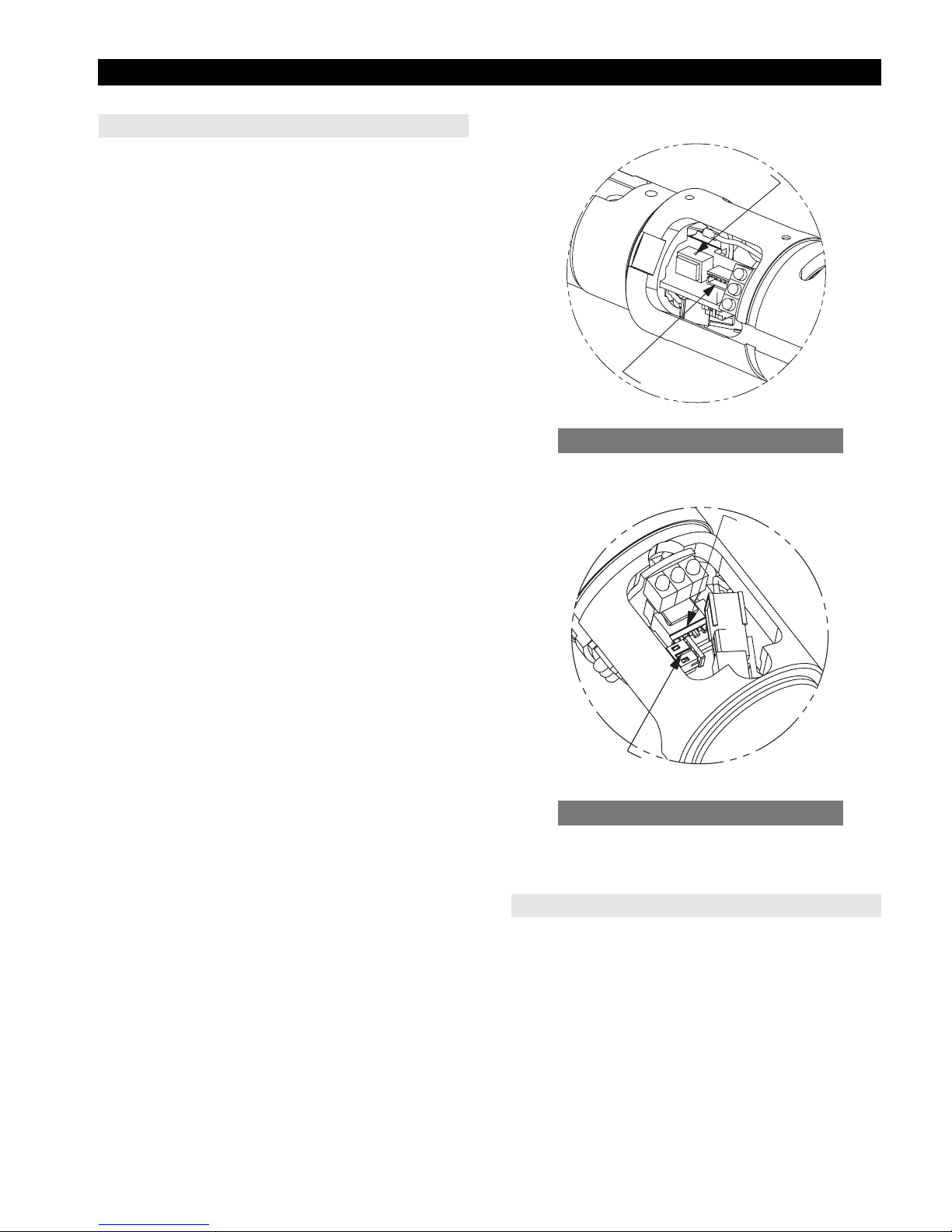
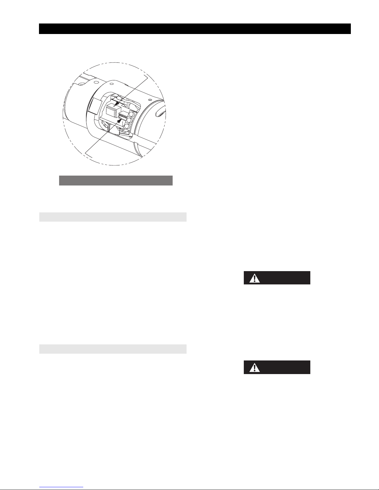
Communication Board
T
Torque and Motor Connector(s)
C
r
o
o
m
t
o
M
o
r
q
u
m
u
t
a
t
i
o
n
r
e
c
u
d
e
s
n
T
a
r
(Dwg. TP2162a)
L
E
D
B
o
a
r
d
s
n
e
S
M
o
t
o
r
T
p
e
m
e
r
u
t
a
r
e
LEDs and Temperature Connector(s)
(Dwg. TP2162b)
Disassembly of Internal Components
1. Remove Retainer (9) used to retain Communication
Board (8), located at rear end of Motor Housing
Assembly in Connector cavity.
2. In large cavity area(s) of Motor Housing, disconnect
the Motor Phase connector.
(Refer to TP2162b)
3. Disconnect the Motor temperature-sensor connector
from the Communication Board.
(Refer to TP2162b)
4. Disconnect the Motor Commutation connector from
the Communication Board.
18
(Refer to TP2162a).
r
o
Page 19
MAINTENANCE (Continued)
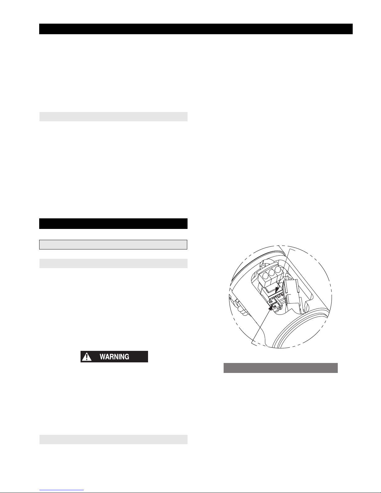
5. Disconnect the Torque Transducer connector from the
Communication Board.
(Refer to TP2162a)
6. Disengage female socket located on front end of Communication Board, from male connector located at
center of LED Board (2) by gently sliding board from
Motor Housing Assembly.
7. Remove LED Board from Motor Housing Assembly.
(Refer to TP2162b)
Transducer Removal
1. Locate the cavity found at end of long axial groove
running along the outer surface of the Motor Housing
Assembly.
2. Make sure the Transducer connector is disconnected
from the Communication Board.
3. Gently pull Transducer (32) out of the Motor Housing
Assembly, while feeding the Transducer wire and
connector through the cavity in the Motor Housing
Assembly.
4. Carefully push Transducer's connector through the
cavity of the Motor Housing Assembly.
ASSEMBLY
three tabs of the LED Board against the three ledges of
the Motor Housing Assembly (Refer to TP2162a)
making sure that the motor commutation wires
properly pass through the cutout in the LED board.
2. Using two of the three internal axial grooves located in
the connector end of the Motor Housing Assembly,
slide Communication Board (8) into Motor Housing
Assembly.
3. Press connector located on front end of Communication Board into socket located at center of LED Board.
4. Route Motor Commutation wiring to same side of
Communication Board; snap connector into socket
marked Motor.
(Refer to TP2162a)
5. Route Motor Temperature Sensor Connector cable to
opposite side of Communication Board; snap Motor
Temperature-Sensor connector into the Motor
Temperature-Sensor socket.
(Refer to TP2162b)
6. Through large cavities of Motor Housing Assembly,
connect Motor Phase Female Connector to Male
Connector of Motor.
7. Install Retainer (9) behind Communication Board in
connector cavity in the end of the Motor Housing
Assembly.
Communication Board (Close-Up)
Motor Housing Assembly
General Instructions
1. To protect the part's surfaces and to prevent distortion
of Housings and threaded joints, use care when
grasping the tool.
2. Always press on the inner ring of a ball-type bearing
when installing the bearing onto a shaft.
3. Always press on the outer ring of a ball-type bearing
when pressing the bearing into a bearing recess.
4. Refer to the "Lubrication" section of this manual for
instruction on how to properly grease this tool.
• This procedure is to be done by an authorized, trained
repair person. To ensure proper functioning of the
tool:
When replacing the Motor Housing Assembly (1), always
ensure that the Memory Chip (7), Communication Board
(8), Gear Case Assembly, and Attachment are all assembled
as a set with the new Motor Housing Assembly.
L
E
D
B
o
a
r
d
r
o
s
n
e
S
M
o
t
o
r
T
p
e
m
e
r
u
t
a
r
e
LEDs and Temperature Connector(s)
(Dwg. TP2162a)
Internal Components
1. Insert the LED Board (2) through one of the Motor
Housing Assembly's three large cavities and lay the
19
Page 20
MAINTENANCE (Continued)
C
r
o
o
m
t
o
M
T
o
r
q
u
Torque and Motor Connector(s)
Transducer Installation
1. Insert Transducer Assembly (32) into the Motor
Housing Assembly, wire end first, guiding
Transducer's connector out through the cavity found at
end of Motor Housing Assembly's long outer groove.
2. Carefully pull Transducer's connector and wiring
through cavity of Motor Housing Assembly.
3. Align and engage Transducer's gear teeth with the gear
teeth located inside the end of the Motor Housing
Assembly. Be certain that the Transducer wire exits the
Transducer directly over the access cavity through
which the wire was fed.
4. Continue inserting the Transducer assembly until it is
fully seated.
5. Snap Transducer's connector into Communication
Board (8) socket marked Torque.
External Components
m
u
t
a
t
i
o
n
r
e
c
u
d
e
s
n
T
a
r
(Dwg. TP2162b)
(Refer to TP2162a)
7. Install and depress Ball (3) and Spring (4) and then
slide Reverse Ring onto Motor Housing Assembly.
When replacing the Motor Housing Assembly (1), always
ensure that the Memory Chip (7), Communication Board
(8), Gear Case Assembly, and Attachment are all assembled
as a set with the new Motor Housing Assembly.
8. Install Memory chip (7) into Housing with terminals
aligned with O-ring groove.
9. Slide two O-rings (15) into groove to retain Memory
chip.
10. Install Spring (6) on post in middle of Trigger (5) and
install Trigger into Motor Housing Assembly.
11. For models with Extended Lever (25), install an
additional spring on Trigger's auxiliary post.
12. Slide Handle Grip (18, 19, 20, or 21) onto Motor Housing Assembly.
13. Apply a medium strength thread locker to Low Head
Socket Cap Screw (22).
14. Install Low Head Socket Cap Screw into Motor
Housing Assembly.
15. Torque Socket Cap Screw to 10 to 15 lb
(1.1 to 1.7 Nm).
f
• in
16. For models with Levers:
a. Place Lever (24 or 25) in position against Handle
Grip and install lever Socket Cap Screws (23).
b. Torque Socket Cap Screw (23) to 5 to 10 lb
(0.5 to 1.1 Nm).
f
• in
WARNING
• This procedure is to be performed by an authorized, trained repair person. To ensure proper
functioning of the tool:
• In the course of disassembling or assembling this
product, beware of any attempt to separate the gear
case from or tighten the gear case to the motor
housing assembly. Destruction of the transducer
wire will result.
1. Slide O-ring (10) into groove located at front end of
Motor Housing Assembly.
2. Slide on Housing Cover (11), ensuring that Transducer
and Motor wires are not disturbed.
3. Slide Warning Label (12) into Label Cover Lens (13).
Note Warning Label and Label Cover Lens slot and tab
alignment features.
4. Slide Label Cover Lens and Warning Label over Motor
Housing Assembly grip area. Orient tabs of Label
Cover Lens with mating slots in Motor Housing
Assembly, and slide together.
5. Install Retaining Ring (14) into groove behind Label
Cover Lens.
6. Place Spring (16) into Reverse Ring (17).
CAUTION
• When replacing an Attachment, always use the
Angle Head Attachment designed for that model.
Never replace an Angle Head Attachment with an
In-Line Attachment.
• When replacing a Gear Case Assembly, always use
the Assembly designed for that model.
20
Page 21

MAINTENANCE (Continued)
Gear Case - Assembly
FOR GEP120-M37 AND GEP150-M37
1. Ensure that all the gears are free of debris.
2. Apply 2-3 cc of IR #67 grease to the central area
between the gears and the surface of the gear teeth of
st
the 1
Stage Spindle Assembly (37) and the 2nd Stage
Spindle Assembly (39).
3. Insert Bearing (51) into threaded end of Gear Case (48)
and push it in until it seats against the shoulder in the
Gear Case.
4. Assembly the Retaining Ring (52) into the groove
directly in front of the Bearing with internal snap ring
pliers.
5. Support the Gear Case Assembly, threaded end down,
on the inner race of Bearing (51).
6. Position the 2
nd
Stage Spindle Assembly (39) on the
inner race of the Bearing (51) inside the Gear Case
with the splined end of the Spindle Assembly facing
the Bearing.
7. With an appropriate tool, press the 2
nd
Stage Spindle
Assembly into Bearing (51) until the Spindle Assembly seats against the inner race of the Bearing.
8. Coat the inside and outside surfaces of the Ring Gear
(43) with IR #67 grease.
9. Insert the Ring Gear into the Gear Case with the end of
the Ring Gear having an internal groove towards the
motor.
10. Align the Ring Gear teeth with those of the planets in
nd
the 2
Stage Spindle Assembly and slide the Ring
Gear into the Gear Case until it stops against the shoulder inside the Gear Case.
11. Install the Retainer (34) into the groove inside the
motor end of the Gear Case to secure the Ring Gear.
12. Insert the 1
st
Stage Spindle Assembly (37) into the
Gear Case and engage the teeth of the gear on the Gear
Head Assembly with the planet gears of the 2
nd
Stage
Spindle Assembly while aligning the planet gears of
the Gear Head Assembly with the Ring Gear.
13. Install Retaining Ring (36) into groove in the end of
the Ring gear.
14. Slide the Coupling Nut (47) on the input end of the
Gear Case (48). Using the proper tool, slide the Retaining Ring (46) over the end and into the groove of the
Gear Case.
FOR GEA240-M37, GEF240-M37 AND GEP240-M37
Assembly (45).
3. Coat the inside and outside surfaces of the Ring Gear
(43) with IR #67 grease.
4. Insert the Spindle Bearing (41) into the fine pitch end
of the Ring Gear (43) with the flanged side of the bearing facing out until the bearing rests in the interior bore
deep inside the ring gear. This may require moderate
pressure.
5. Engage the planets of the 3
rd
Stage Spindle (45),
squared end out, with the Ring Gear and insert it until
it contacts the installed Spindle Bearing (41)
6. Position the Assembly of the previous step with the 3
Stage Spindle resting on the table of an arbor press.
7. With an appropriate tool, press the inner race of the
Spindle Bearing (41) onto the 3
rd
Stage Spindle
Assembly until the Spindle Assembly seats against the
inner race of the Bearing.
8. Apply a coating of Ingersoll Rand #67 grease to the
Spacer (40) and install the spacer on top of the Spindle
Bearing (41).
9. Install the 2
nd
Stage Spindle (39). Be sure to engage all
gears properly prior to applying any force.
10. Apply a coating of Ingersoll Rand #67 grease to the
Spacer (38) and install the spacer on top of the 2
nd
Stage Spindle (39).
11. Install the 1
st
Stage Spindle (37). Be sure to engage all
gears properly prior to applying any force.
12. Install the Retainer (36) into the groove inside the
motor end of the Ring Gear.
13. Install the Ring Gear containing the Spindles, output
end first, into the Gear Case (48) .
14. Install Retaining Ring (34) into the internal groove in
the end of the Gear Case.
15. Slide the Coupling Nut (47) onto the input end of the
Gear Case (48). Using the proper tool, slide the Retaining Ring (46) over the end and into the external groove
of the Gear Case.
FOR GEF400-M37, AND GEP400-M37
1. Ensure that all the gears are free of debris.
2. Apply 3 - 4 cc of IR #67 grease to the central area
between the gears and the surface of the gear teeth of
st
the 1
Stage Spindle Assembly (37), the 2nd Stage
Spindle Assembly (39) and the 3
rd
Stage spindle
Assembly (45).
3. Coat the inside and outside surfaces of the Ring Gear
(43) with IR #67 grease.
rd
1. Ensure that all the gears are free of debris.
2. Apply 3 - 4 cc of IR #67 grease to the central area
between the gears and the surface of the gear teeth of
st
the 1
Stage Spindle Assembly (37), the 2nd Stage
Spindle Assembly (39) and the 3
rd
Stage spindle
21
Page 22

MAINTENANCE (Continued)
4. Engage the planets of the 3rd Stage Spindle (45) with
the large outer diameter end of the Ring Gear and
insert it until its spindle bearing seats in the Ring Gear
bearing bore.
5. Apply a coating of Ingersoll Rand #67 grease to the
Spacer (40) and install the spacer on top of the 3
rd
Stage Spindle (45) from the small outer diameter end
of the Ring Gear.`
6. Install the 2
nd
Stage Spindle (39). Be sure to engage
all gears properly prior to applying any force.
7. Apply a coating of Ingersoll Rand #67 grease to the
Spacer (38) and install the spacer on top of the 2
nd
Stage Spindle (39).
st
8. Install the 1
Stage Spindle (37) Be sure to engage all
gears properly prior to applying any force.
9. Install the Retainer (36) into the groove inside the
motor end of the Ring Gear.
10. Install the Ring Gear containing the Spindles, output
end first, into the Gear Case (48) .
11. Assembly O-ring (31) into the proper internal groove
in the output end of the Motor Housing Assembly.
12. Slide the Coupling nut (47), threaded side first over the
Motor Housing Assembly.
13. FOR GEP400-M37 ONLY:
a. Assemble Retaining ring (49) to groove in Spindle
(50)
b. Insert Spline of Spindle (50) into 3
rd
Stage Spindle
(45)
FOR MODELS WITH OFFSET GEAR CASES:
QE8Z{ }070{ }{ }
QE8Z{ }090{ }{ }
QE8Z{ }150{ }{ }
1. Insert Gear Case into the Offset Gearcase Input Flange.
2. Align the flange holes of the Offset Gear Case flange
and Tool Gear Case and thread the Cap Screws into
the Tool Gear Case flange.
3. Torque Cap Screws as follows:
QE8Z{ }070{ }{ }, QE8Z{ }090{ }{ } and
QE8Z{ }150{ }{ }
18.4 - 25.4 ft • lbs (25 - 34.5 Nm)
FOR OFFSET GEARING ASSEMBLY:
REFER TO THE APPROPRIATE MAINTENANCE
MANUAL LISTED IN THE QE8 HIGH TORQUE GEARING PARTS LIST.
Gear Case Assembly Installation
ALL MODELS
1. Install the Pinion Coupler Assembly (35) on the pinion
of the motor.
2. Rotate the Gear Case Assembly to the desired orientation relative to the Motor Housing Assembly (1).
3. Insert the Motor Housing Assembly (1) into the Gear
Case (48).
4. Align and engage the gear of the Pinion Coupler
Assembly (35) with the Planets of the 1
st
Stage Gear
Head Assembly (37) while engaging the Ring Gear
(43) with the Transducer (32) teeth. It may be
necessary to rotate the 3
rd
Stage Spindle Assembly
(39) to aid in assembly.
5. Thread Coupling Nut (47) to the appropriate threads
and while using the appropriate tool and the spanner
holes on the gearcase torque the Coupling Nut (47) to
50 - 60 ft • lbs
(68 - 81 Nm).
22
Page 23

MAINTENANCE (Continued)
Attachments
In-Line Attachment - Assembly
FOR 160E4S8, 160E6S8 & 160E8S8 IN-LINE
ATTACHMENTS
1. Install Socket Retaining Pin (66) into small hole
provided in one of the flat walls of the square Spindle.
2. With Pin in place, locate Pin's groove inside large
end-hole of Square Drive Spindle (64).
3. Position Spring (65) inside large hole of Square Drive
Spindle such that the free ends of the Socket Retaining
Spring are faced away from the hole and the closed
side of the Spring straddles the Socket Retaining Pin.
4. Holding the Socket Retaining Pin steady, push Spring
down hole of square Spindle until the Socket Retaining
Spring's wire engages Socket Retaining Pin.
5. Socket Retaining Pin is properly installed when Socket
Retaining Spring snaps into place.
6. Lubricate the bearings of the Housing Assembly (61)
with Ingersoll-Rand # 67 Grease.
7. Slide Washer (62) and Washer (63) onto Square Drive
Spindle and insert Square Drive Spindle (64) into
Housing Assembly (61).
8. Align the Coupler (67) to slide over spline of Square
Drive Spindle.
9. Slide Coupler into position in Housing Assembly (61).
10. Slide Washer (70) on the Drive Spindle Assembly (69).
11. Use snap-ring Pliers to install the Retaining Ring (71)
on top of the Washer.
12. Press on Rear Spindle Bearing (72) to Drive Spindle
Assembly (69).
13. Place Disengaging Spring (68) over Drive Spindle
Assembly.
14. Align the Drive Spindle Assembly with spline of
Coupler and insert Drive Spindle Assembly into
Housing Assembly (61).
15. Apply one drop of Perma-Lok MM-115 to threads of
Bearing Cap (73).
16. Carefully grasp the Housing Assembly.
Note: In the following step, the Bearing Cap (73) has a
left-hand thread.
17. Using the appropriate tool, tighten Bearing Cap (73) to
between 45 - 50 lb
• ft (61 - 68 Nm) of torque.
f
18. Slide Coupling Nut (74) over Housing Assembly (61).
19. Using an appropriate tool, install Retainer (75) onto
spline of Housing Assembly until seated into groove.
20. Spin Coupling by hand to check freedom of movement.
FOR ALL OTHER SPINDLE ASSEMBLIES:
REFER TO THE APPROPRIATE MAINTENANCE
MANUAL LISTED IN THE QE8 HIGH TORQUE INLINE SPINDLE PARTS LIST.
Attachment - Installation
FOR MODELS:
QE8A{ }225{ }{ }
QE8A{ }400{ }{ }
QE8S{ }150{ }{ }
1. Position the Attachment appropriately.
2. Engage the spline on the input spindle of the
Attachment with the matching internal spline of the
rd
3
Stage Spindle Assembly (45), and then engage the
spline on the Attachment Housing with that of the Gear
Case (48).
3. Thread the Coupling Nut (74) onto the Gear Case.
4. While holding the tool using an appropriate wrench on
the wrench flats (or spanner holes) of the Gear Case,
torque Coupling Nut to between 45 - 50 lb
(61 - 68 Nm).
f
• ft
FOR ALL OTHER MODELS:
1. Insert Gear Case or Offset Gear Case into the Tool
mounting plate.
2. Insert Attachment to the Opposite side of the Mounting
Plate and properly engage the drive spindle with the
Gear Case or Offset Gear Case Output Spindle.
3. Align the mounting holes of the Attachment to the
Mounting plate and to the Gear Case or Offset Gear
Case and insert the Cap Screws through the holes in the
flange of the Attachment and mounting plate.
4. Torque Cap Screws to the Gear Case or Offset Gear
Case as follows:
ALL MODELS:
18.4 - 25.4 ft • lbs (25 - 34.5 Nm)
23
Page 24
MAINTENANCE (Concluded)
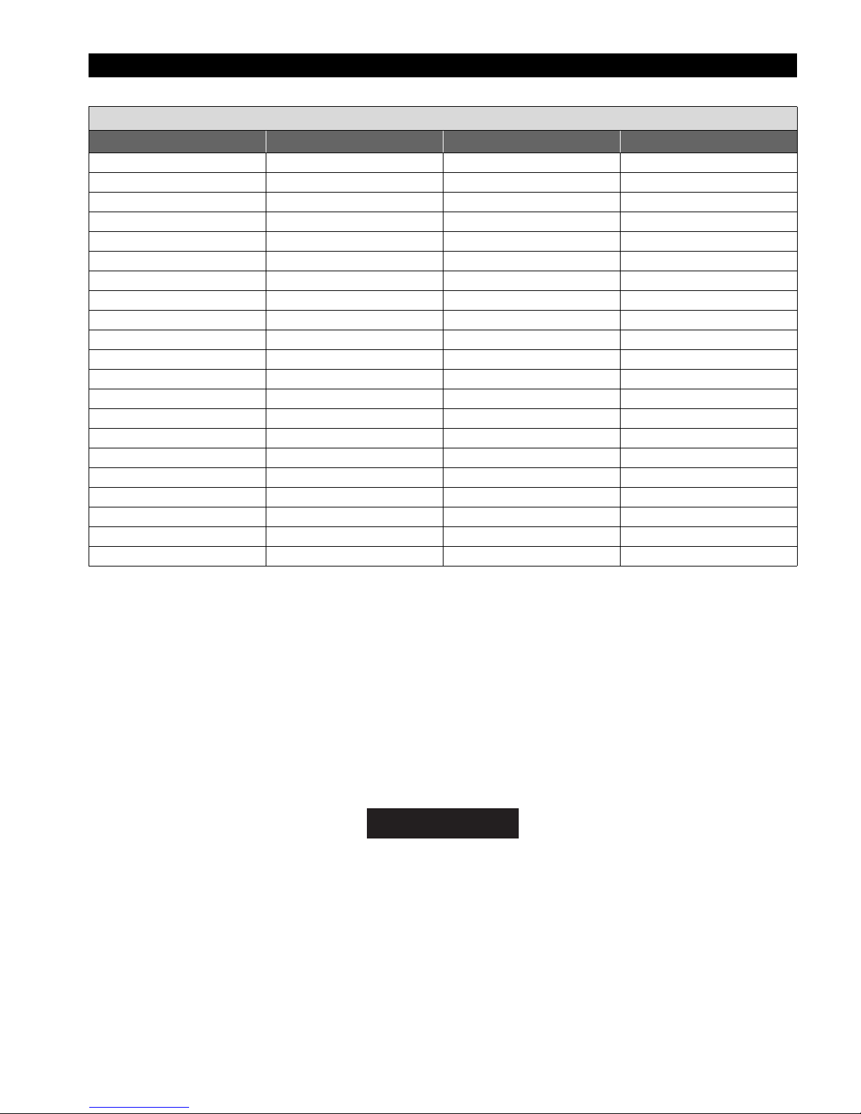
QE8 Series Wiring (Cable) Chart
Connector Pin Wire Color (Cable) Logic Connector Pin
ARedVCC13
B Black COM 14
C Gray Spare 1 12
D Pink Spare 2 27
E Brown Spare 4 15
F Yellow Sine 21
G Orange Cosine 28
H Violet Spare 3 7
J Green Ground Sense 20
KBlueRX+ 5
L Blue/White RX- 6
MWhiteTX- 8
N White/Blue TX+ 9
U Red Motor Phase B 23
V Black Motor Phase C 34
W White Motor Phase A 36
X Green/Yellow Ground 25
--- --- TX Shield 1
--- --- RX Shield 4
--- --- Hall Shield 22
--- --- Motor Shield 16
SAVE THESE INSTRUCTIONS. DO NOT DESTROY.
When the life of the tool has expired, it is recommended that the tool be disassembled,
degreased and the parts be separated by material so that they can be recycled.
NOTICE
24
Page 25

SERVICE NOTES
25
Page 26

SERVICE NOTES
26
Page 27

SERVICE CENTERS
Centres d’entretien • Ingersoll-Rand Niederlassungen • Centri di Assistenza •
Centros de Servicio • Service Centra • Servicentre • Servicecenter • Servicesenter •
Huoltokeskus • Centros de Assistência Técnica • Κέντοα Εξυποέτησης
Ingersoll-Rand
1872 Enterprise Drive
Rochester, MI 48309
Phone: (248) 293-5700
Fax: (248) 293-5800
Asia Pacific Operations
Ingersoll-Rand Ltd.
42 Benoi Road
Jurong, Singapore 629903
Phone: 65-861-1555
Fax: 65-861-0317
Australia
Ingersoll-Rand Ltd.
Landmark Corporate Center
Level 2
454-472 Nepean Highway
Frankston, Vic 3199
Australia
Phone: 61 3 8781 1600
Fax: 61 3 8781 1611
Canada
National Sales Office
Regional Warehouse
Toronto, Ontario
51 Worcester Road
Rexdale, Ontario M9W 4K2
Phone: (416) 213-4500
Fax: (416) 213-4510
Order Desk
Fax: (416) 213-4506
China
Ingersoll-Rand Productivity Solutions
Room 1616, South Tower,
Guangzhou World Trade Center Complex,
371 Huanshi East Road
Guangzhou, 510095
China
[86] 20 8776 4754 or 86 20 8776 4755
UK
Ingersoll-Rand & Co. Ltd.
Swan Lane (Gate 3)
Hindley Green
Wigan WN2 4EZ UK
Phone: +44 (0) 1942 257 171
Fax: +44 (0) 1942 503 450
OFFICE LOCATIONS
Czech Republic
Ingersoll-Rand Productivity Solutions
Ostrovskeho 34 151 28 Prague
Czech Republic
Phone: +420 2 57 109 756/7
Fax: +420 2 57 109 758
France
Ingersoll-Rand Productivity Solutions
A.S. Division
Zone du Chêne Sorcier
B.P. 62
Les Clayes sous Bois Cedex 78346
Phone: +33 (0) 1 30 07 69 00
Fax: +33 (0) 1 30 07 69 82
Germany
Ingersoll-Rand European Sales Ltd.
c/o Intersoll-Rand GmbH
Postfach 10 09 54
45409 Mülheim / Ruhr Germany
Phone: +49 (0) 208 9994 0
Fax: +49 (0) 208 9994 444
e-mail: [email protected]
India
Ingersoll Rand Wadco Tools Pvt. Limited
37-A, Site-4, Sahibabad Industrial Area
Ghaziabad-201 010 India
Tel : +91-120-2895116-126
Fax: +91-120-2895127
Italy
Productivity Solutions
Ingersoll-Rand Italia S.r.l.
Strada Provinciale Cassanese 108
20060 Vignate (Milano), Italy
Phone: +39 02-95056-261
Fax: +39 02-95360-159
India
Ingersoll Rand Wadco
Tools Pvt. Limited
37-A, Site-4, Sahibabad
Industrial Area
Ghaziabad-201 010 India
Tel : +91-120-2895116-126
Fax: +91-120-2895127
27
Page 28

OFFICE LOCATIONS (CONTINUED)
Japan
IR Japan, Ltd.
LS Bldg. 2F, 1-1-17 Kami-Ohsaki, Shinagawa-ku
Tokyo, 141-0021
Japan
[81] 3-5420-3397
Latin America Operations
Ingersoll-Rand
730 N.W. 107 Avenue
Suite 300, Miami, FL, USA
33172-3107
Phone: (305) 559-0500
Fax: (305) 222-0864
Europe, Middle East and Africa
Ingersoll-Rand
Douai Operations
111, Avenue Roger Salengro
59450 Sin Le Noble, France
Phone: (33) 3-27-93-08-08
Fax: (33) 3-27-93-08-00
Poland
Nowiniarska 1 ap. 1
00-235 Warsaw Poland
Phone: +48 (0) 22 635 7245
Fax: +48 (0) 22 635 7332
Russia
Ingersoll-Rand Company
Mjasnitskaya Street, 32, bld. 1
101990 Moscow
Russia
Phone: +7 (8) 095 933 03 24
Fax: +7 (8) 095 785 21 26
Scandinavia
Ingersoll-Rand
Drammensveien 126 A
0277 Oslo Norway
Phone: +47 (0) 22 55 15 26
Fax: +47 (0) 22 43 65 81
Spain
Ingersoll-Rand Productivity Solutions
Tierra de Barros, 2
28820 - Coslada
Madrid (Spain)
Phone: +34 (0) 91 6277405 / 6277400
Fax: +34 (0) 91 6277406
South Africa
Ingersoll-Rand Company SA (PTY) Ltd.
Productivity Solutions
P.O. Box 123720
Alrode 1451
South Africa
Phone: +27 (0) 11-617-3828
Fax: +27 (0) 11-864-5609
UK
Ingersoll-Rand & Co. Ltd.
Swan Lane (Gate 3)
Hindley Green
Wigan WN2 4EZ UK
Phone: +44 (0) 1942 257 171
Fax: +44 (0) 1942 503 450
USA
Ingersoll-Rand Productivity Solutions
P.O. Box 970
1467 Route 31 South
Annandale, NJ 08801
Phone: (908) 238-7000
Fax: (908) 238-7048
28
0404
 Loading...