

Page 1

16609703
Edition 1
March 2009
Save These Instructions
DC Electric Tool
QE2 Series
Maintenance Information
CALL TOLL FREE 877-742-2878 FOR SALES AND SUPPORT
Return to BurtProcess.com
Page 2

2 16609703_ed1
General Instructions
Refer to “Suggested Tools Parts List” for quick reference to the
tools recommended for the following disassembly/assembly
instructions.
WARNING
Repairs should be made only by authorized trained personnel.
Consult your nearest Ingersoll Rand Authorized Service
Center.
Disconnect the power cord from the receptacle before
performing any maintenance on this or any other tool.
Always use protective eyewear when performing maintenance
on a tool or while operating a tool.
Use of non-Ingersoll Rand parts or failure to follow
Maintenance Instructions may create a risk of electric shock
or injury.
Note: When reading instructions refer to exploded diagrams in
Parts Information manual when applicable (see under related
documentation for form numbers).
•
•
•
•
•
Lubrication
Whenever this product is disassembled, clean the parts and
re-lubricate them as follows:
1. Clean and degrease all parts except for the 1st stage Gear
Assembly and 2nd stage Spindle Assembly (46).
2. Wipe clean the 1st stage Gear Assembly and 2Assembly and 2 and 2nd stage Spindle
Assembly with a clean, dry and lint-free rag. with a clean, dry and lint-free rag.
3. Once cleaned, apply prescribed amounts of Ingersoll Rand
#67 Grease as follows:
2 to 3 cc to central area between gears of 1st stage Gear
Assembly and 2nd stage Spindle Assembly.
1 to 2 cc to faces of 1st stage Gear Assembly and 2nd stage
Spindle Assembly.
Thin layer on Ring Gear teeth.
Thin layer on faces of Washers and O-Ring.
4. For Models with an Angle Assembly Attachment: Use
Ingersoll Rand #67 Grease to lubricate Angle Head through
Grease Fitting.
5. For Models with an In-Line Attachment: Use Ingersoll Rand
#67 Grease to lubricate the Drive Spindle Bearings (117), the Drive
Spindle (122), the Spring (124, 125) and the Needle Bearing (116).
6. For Models with Pistol Attachment: Use Ingersoll Rand #67
Grease to lubricate Pivot Pin (36). Use Ingersoll Rand #160
O-Ring Lube to lubricate sliding surface of Trigger Lever (32).
•
•
•
•
Disassembly
WARNING
This procedure is to be performed by an authorized, trained
repair person. To ensure proper functioning of the tool.
When replacing the Motor Housing Assembly (1), always
ensure that the Main Board Assembly (2), Transducer
Assembly (9), Gear Pack Assembly, Spindle Assembly and
Attachment are all assembled as a set with the new Motor
Housing Assembly.
CAUTION
When replacing an Attachment, always use the Assembly
Attachment designed for that model. Never replace an Angle
Assembly Attachment with an In-Line Attachment.
When replacing a Transducer Assembly, Gear Pack Assembly,
always use the Assembly designed for that model.
General Instructions for Disassembly
1. Do not disassemble the tool any further than necessary to replace
or repair damaged parts.
2. To protect part surfaces and to prevent distortion of Housings
and threaded joints, use care when grasping the tool.
3. Avoid clamping non-metal surfaces, unless directed otherwise.
4. Do not remove any press t part or any part of an assembly
unless its removal is necessary for repair or replacement.
Disassembly of Grips and Plastic Components
1. For Models with Levers, use the appropriate hex. key to loosen
Socket Head Cap Screws (16) from Lever (14) and remove Lever
and Spacer (19) from Motor Housing Assembly (1).
2. For Models with Pistol Attachment,
Use the appropriate hex. key to loosen Socket Head Screw (37).
Remove Housing Clip (33) and Hanger Suspension Clip (35)
from the Pistol Handle Set (38).
Remove the Pistol Handle Set from the Motor Housing
Assembly (1).
3. For Models with Lever and Models with Pistol attachment,
remove the Lever Button Housing Assembly (18) from the Motor
Housing Assembly (1) using designated tool.
•
•
•
•
•
•
•
4. For all Models, use the appropriate hex. key to loosen low Head
Cap Screw (15) from Suspension Nut. Slide the Suspension
Nut (7) o of Motor Housing Assembly (1).
5. Slide O-Ring (12), Lens cover (6) and Label (13) o of Motor
Housing Assembly (1).
6.
For Push To Start Models and Models with Lever, use
appropriate hex. key to loosen Low Head Cap Screw (17) from the
Main Cover (5).
Push down reverse button (8) and slide Main Cover (5) o of
Motor Housing Assembly (1).
If applicable, slide Hand Flange (4) and O-Ring (11) o of
Motor Housing Assembly (1).
7. For Models with Pistol Attachment, use appropriate hex. key
loosen the Socket Head Screw (37) from the Pistol Housing
Key (34). Remove the Pistol Housing Key.
Attachments
WARNING
NEVER grasp the tool in a vise, as this will likely result in
damage to the tool causing wire leads to malfunction, which
increases risk of electric shock.
CAUTION
When installing or removing a Coupling Nut, use the
designated tool, a Hook Spanner Wrench or similar wrench to
hold the tool, and use a Spanner Wrench to tighten or loosen
the Coupling Nut.
Disassembly of Internal Components
(Common to all Models)
1. Remove the access cover (3).
2. If required, remove the Reverse Button Housing Assembly (8)
from the Access Cover (3) using Button Housing Socket,
CPS2-38-2T.
3. Through the access hole in housing, disconnect the Motor Phase
connector.
4. Disconnect the Motor temperature-sensor connector from the
Main Board Assembly (2).
•
•
•
•
Page 3

16609703_ed1 3
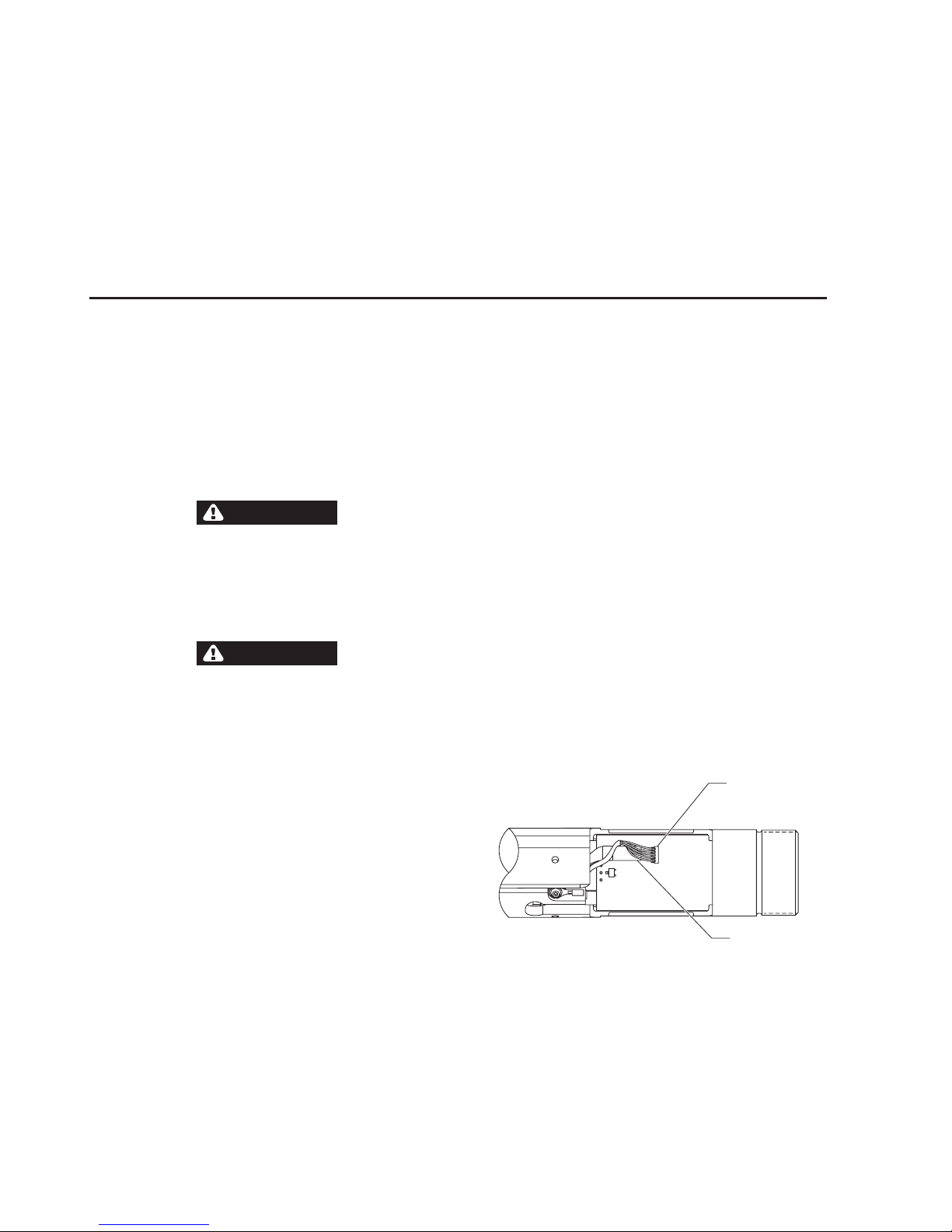
Motor Phases
Connector
Motor Commutation
Socket
Motor Temperature
Sensor Socket
(Dwg. 45540291a)
5. Disconnect the Torque Transducer connector from the
Main Board Assembly (2).
6. Disconnect the Flex PCB (64) from the Main Board Assembly (2).
Torque
Transducer
Socket
Flex PCB
Socket
(Dwg. 45540291b)
7.
Disconnect the Motor commutation connector from the
Main Board Assembly (2).
8. Remove Retainer (20).
9. If necessary, remove the Main Board Assembly (2) from
Motor Housing Assembly (1).
Output Spindle End - Disassembly
1. Disassemble the grips and plastic components..
2. For In-line and Pistol Models,
Using CPS2-25F-70 Fixture Plug, a Hook Spanner Wrench or
similar wrench to hold the tool, and using Spanner Wrench
CPS2-478 (or other appropriate wrench), unscrew Coupling
Nut (81).
Use caution while removing coupling nut. If spindle assembly
becomes disengaged from main housing keys spindle assembly
can rotate causing damage to the ex circuit. Spindle housing
must be held engaged with motor housing keys during nut
disassembly.
Remove the Spring (83).
3. For Angle and Fixtured Models,
Using CPS2-25F-70 Fixture Plug, a Hook Spanner Wrench or
similar wrench to hold the tool, and using Spanner Wrench
CPS2-478 (or appropriate wrench), unscrew Coupling Nut (92).
Note: Left hand thread.
Remove the Angle Head (91) or In-line Attachment.
Remove the Lock Washer (104) o of Spindle Coupling (103).
Using a CPS2-25F-70 Fixture Plug, a Hook Spanner Wrench or
similar wrench to hold the tool, and using Spanner Wrench CPS2478 (or appropriate wrench), unscrew Spindle Coupling (103) o
Spindle Housing (102).
Note: Left hand thread
Remove Light Ring Lens (106) o of Spindle Housing (102).
Using CPS2-25F-70 Fixture Plug, a Hook Spanner Wrench or
similar wrench to hold the tool, and using Spanner Wrench
CPS2-478 (or appropriate wrench), unscrew Coupling Nut (107)
o Motor Housing Assembly (1). Use caution while removing
coupling nut. If spindle assembly becomes disengaged from
the main housing keys the spindle assembly can rotate causing
damage to the ex circuit.
•
•
•
•
•
•
•
•
•
Remove Spindle Housing (102) .
If required, remove Flex PCB (105) from the Spindle Housing (102).
If required, Remove Retainer (99) o of Bit Holder Plug
Assembly (98).
If required, Remove Bit Holder (76).
Remove Hall Housing (72) from Spindle Housing (102).
Angle Attachment Disassembly
1. For 3/8” and 1/4” Square Drive Spindles,
Looking down hole of the Spindle’s square socket, locate
Retaining Pin (95) and Retaining Spring (94).
If necessary, use a pointed metal probe to pull retaining
Spring out of Spindle cavity.
If necessary, remove Pin from Spindle.
2. For Quick Change Spindles, remove Bit Retaining Spring (97)
and Bit Retaining Ball (96).
3. Using CPS2-25F-70 Fixture Plug, a Hook Spanner Wrench or
similar wrench to hold the tool, and using Spanner Wrench
CPS2-478 (or other appropriate wrench), unscrew Coupling
Nut (92) and pull the Angle Assembly Attachment (91) out of
Motor Housing Assembly (1).
4. If necessary, remove Coupling Nut Retainer (93) using an
appropriate tool.
In-Line Attachment Disassembly
1. Using CPS2-25F-70 Fixture Plug, a Hook Spanner Wrench or
similar wrench to hold the tool, and using Spanner Wrench
CPS2-478 (or other appropriate wrench), unscrew Coupling
Nut (92) and pull the In-Line Attachment out of Motor Housing
Assembly (1).
2. If desired, remove Coupling Nut Retainer (93) using the
appropriate tool.
Note: In the following step, the Bearing Cap (119) has a lefthand
thread.
3. Using CPS3-532T Hex Socket or an adjustable Pin Wrench,
unscrew Bearing Cap (139).
4. Pull the Drive Spindle Assembly (142) out of Housing (141).
5. Remove the Retaining Ring (138). If necessary, using a bearing
puller tool, press the Rear Spindle Bearing (137) o the Drive
Spindle Assembly.
6.
Tilt Spindle Housing, causing the Spring (144, 145), Square Drive
Spindle (140), and Washer (143) to slide out.
7. Note that the No-Float Models have an extra Spacer (146) inside
the Spindle (140).
Spindle Assembly - Disassembly
(Common for Push to start, Trigger and Pistol Model)
1. Remove the Hall Holder (72) from the Spindle Sub Assembly (74).
2. Remove Retainer (69) from the Bit Holder (76, 80).
3. Slide the Push to Start Assembly (73) and Thrust Washer (71) o of
Bit Holder (76, 80).
Note that the No-Float Models have an additional Spacer (81).
4. Slide the Bit Holder (76, 80) out of the Spindle Assembly from the
front end.
5. Use appropriate hex. Key to loosen the Cap Screws (70) from the
Front Spindle Housing (65).
6. Remove the Front Spindle Housing (65).
7. Remove the Light Ring Lens (67).
8. If necessary, disassemble the Flex PCB (64) from the Spindle Sub
Assembly (74).
9. For Quick change type Bit Holder - Remove the Retainer (63)
from the Bit Holder (76). Remove the Spacer (68) and
Spring (62). Remove the Collar (66) from the Bit Holder (76).
Remove the ball (61) from the Bit Holder (76).
10. For Square type Bit Holder - Remove the Rubber Insert (77)
from the Bit Holder (76) using a pick or other appropriate tool.
Remove the retaining pin (78) from the Bit Holder (76).
•
•
•
•
•
•
•
•
Page 4
4 16609703_ed1
Gear Assembly Removal
(Common for all models)
1.
Once the Spindle Assembly has been disassembled, slide the Gear
Assembly out of the Motor Housing Assembly (1).
Transducer Assembly Removal
(Common for all models)
1. Make sure that the Transducer Assembly (9) connector is
disconnected from the Main Board (2).
2. Pull Transducer Assembly (9) out of the Motor Housing
Assembly (1), feeding the transducer wire through the hole in the
Motor Housing Assembly.
Gear Pack - Disassembly
(Common to all models)
1. Remove the 2nd stage Spindle Assembly (46) from the front end of
the Ring Gear (48).
2. Slide the 1st stage Gear Assembly and the Washer (47) from the
Ring Gear (48).
3. If required remove the O-Rings (52, 53) from their respective
grooves in the Ring Gear (48).
Assembly
Motor Housing Assembly
General Instructions
1. To protect the part’s surfaces and to prevent distortion of
Housings and threaded joints, use care when grasping the tool.
2. Always press on the inner ring of a ball-type bearing when
installing the bearing onto a shaft.
3. Always press on the outer ring of a ball-type bearing when
pressing the bearing into a bearing recess.
4. Refer to the “Lubrication” section of this manual for instructions
on how to properly grease this tool.
WARNING
This following procedures are to be performed by an
authorized, trained repair person. To ensure proper
functioning of the tool.
When replacing the Motor Housing Assembly (1), always
ensure that Main Board Assembly (2), Transducer
Assembly (9), and Attachment are all assembled as a
set with the new Motor Housing Assembly.
CAUTION
When replacing an Attachment, always use the Assembly
Attachment designed for that model. Never replace an Angle
Assembly Attachment with an In-Line Attachment.
When replacing a Transducer Assembly (9), always use the
Assembly designed for that model.
Gear Pack - Assembly
(Common to all models)
1. Apply Grease (Ingersoll Rand #67) to Ring Gear Teeth (48).
2. Grease the planet gear teeth of the 1st stage Spindle
Assembly, and slide it into Ring Gear (48) from the front end.
3. Grease and place the Washer (47) into Ring Gear (48) against the
face of the 1st stage Spindle Assembly.
4. Grease the planet gear teeth of the 2nd stage gear assembly (46)
and slide into the gear pack assembly, taking care to align gear
teeth of the 1st stage gear assembly with the planet gears of
the 2nd stage Spindle Assembly.
5. Apply grease to O-Ring (52) and install into the groove of Ring
Gear (48).
6. Place Washer (54) into O-Ring (52) and against the shoulder in the
Ring Gear (48).
7. Apply grease to O-Ring (53) and install into the groove of Ring
Gear (48).
8. To assure free rotation of assembly, hold Gear Pack Assembly
steady, and manually rotate the 2nd Stage Gear Assembly.
Push-to-Start, Lever-to-Start and Pistol Model
Assembly Installation
1. Slide the Main Board Assembly (2) into the Motor Housing
Assembly (1).
•
•
•
•
2. Install Retaining Ring (20) into Motor Housing Assembly (1).
3. Feed transducer cable and connector through hole in motor
housing and slide the Transducer Assembly (9) into the Motor
Housing Assembly. Align gear teeth of transducer assembly with
matching teeth of Motor Housing Assembly.
4. Guide the transducer cable through the long outer slot in motor
housing assembly and connect it to its perspective terminal,
marked “TORQUE” on the Main Board Assembly (2).
5. Apply grease (Ingersoll Rand #67) on outer diameter of Ring
Gear (48) and slide it into the Motor Housing Assembly (1) while
ensuring that the ring gear tabs line up with the slots in the
transducer and the tabs of 2nd Stage Spindle Assembly (46) lines
up with the slots on the Motor Housing Assembly (1).
6. Push Spring (83) against Gear Pack Assembly.
7. Assemble the spindle assembly ensuring engagement of Bit
Holder (76, 80) with the 2nd stage Spindle Assembly (46) of
planetary gear system and also ensuring that the Flex PCB (64) of
the spindle assembly aligns with the slot in the Motor Housing
Assembly (1).
8. Using CPS2-25F-70 Fixture Plug, a hook spanner wrench or similar
wrench to hold the tool, and using Spanner wrench CPS2-478 (or
appropriate wrench), Screw Coupling Nut (81) onto the Motor
Housing Assembly (1). Use caution while tightening coupling nut.
If spindle assembly becomes disengaged from main housing keys
spindle assembly can rotate causing damage to the ex circuit.
Spindle housing must be held engaged with motor housing keys
during nut assembly.
9. Guide the Flex PCB (64) through the long outer slot in Motor
Housing Assembly (1) and connect it to its perspective terminal
on Main Board Assembly (2).
Torque
Transducer
Socket
Flex PCB
Socket
(Dwg. 45540291b)
10. Connect the motor phase connector to its perspective terminal
on the Main Board Assembly (2).
11. Connect the motor temperature sensor connector to its
perspective terminal on the Main Board Assembly (2).
12. Connect the motor commutation socket to its perspective terminal,
marked “RESOLVER” on the on the Main Board Assembly (2).
Page 5
16609703_ed1 5
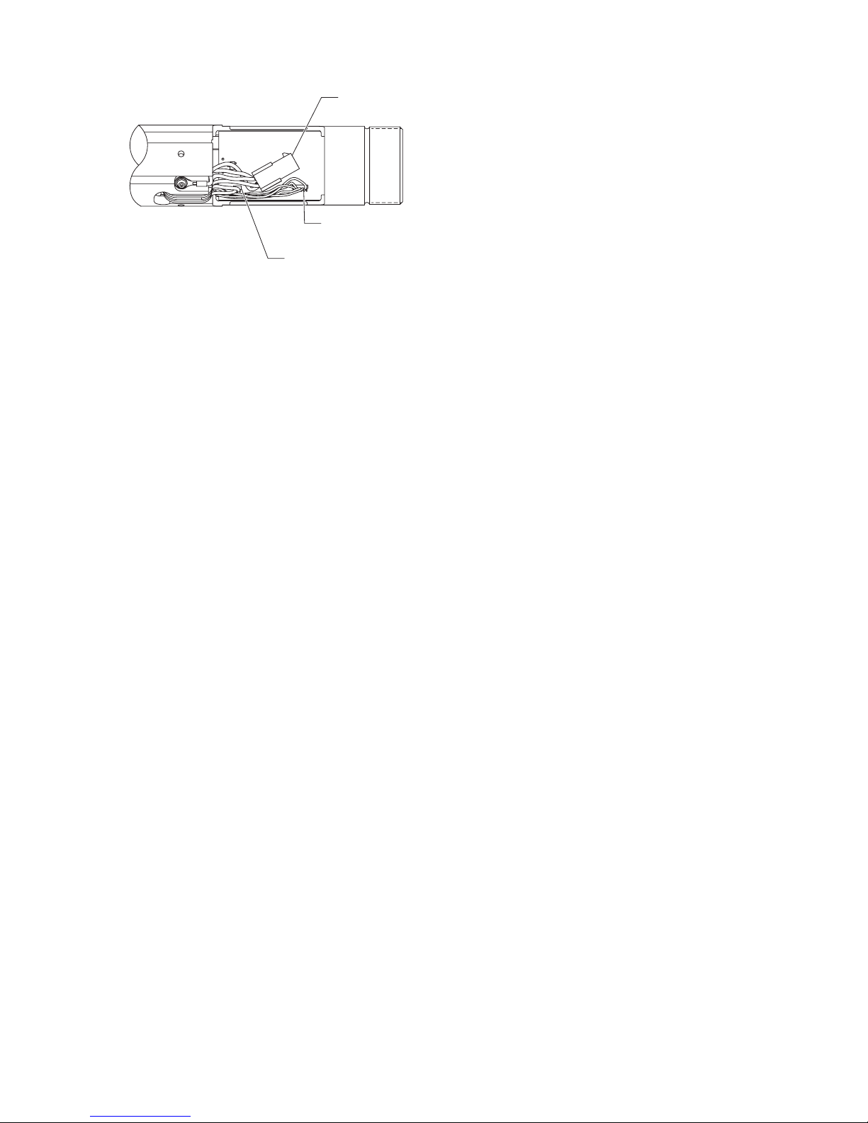
Motor Phases
Connector
Motor Commutation
Socket
Motor Temperature
Sensor Socket
(Dwg. 45540291a)
13. Assemble the Reverse Button Housing Assembly (8) onto the
Access Cover (3) using Button Housing Socket, CPS2-38-2T.
14. Assemble the Access Cover (3) onto the Motor Housing
Assembly (1).
15. For straight models, install the O-Ring (11) onto the Coupling
Nut (81).
16. For Push to Start Model and Models with a Lever,
Slide the Hand Flange (4) on the Motor Housing Assembly (1)
aligning the slots with the tabs of the Coupling Nut (81).
Assemble the Main Cover (5) onto the Motor Housing
Assembly (1) and install Cap Screw (17).
Install the label (13) into the Lens Cover (6) aligning the cutout
in the label with the tabs on the Lens Cover (6)
Assemble the lens cover (6) onto the Motor Housing
Assembly (1).
Install the O-Ring (12) onto the Motor Housing Assembly (1)
and against the Lens Cover (6).
Assemble the Suspension Nut (7) onto Motor Housing
Assembly (1) and install Low Head Cap Screw (15).
17. For Models with a Lever,
Assemble the Lever Button Housing Assembly (18) onto the
Motor Housing Assembly (1) using Button Housing Socket,
CPS2-38-2T.
Use appropriate hex. Key, fasten the Screws (16) onto the
Motor Housing Assembly (1) with the Spacers (19) and the
Lever (14) installed.
18. For Pistol Model,
Assemble the Lever Button Housing Assembly (18) onto the
Motor Housing Assembly (1) using Button Housing Socket,
CPS2-38-2T.
Assemble the Pistol Housing Key (34) onto the Motor Housing
Assembly (1) using the Socket Head Screw (37).
Install the Pivot Pins (36) into the respective holes in one half
of the Pistol Handle Set (38).
Assemble Trigger (31) and Trigger Lever (32) onto the
Pivot Pins (36).
Place Motor Housing Assembly (1) into half of the Pistol
Handle Set (38).
Assemble other half of Pistol Handle Set (38) onto Motor
Housing Assembly (1) and secure the 2 halves together using
Socket Head Screws (37).
Install the Housing Clips (33) to clamp the Pistol Handle
Set (38).
Install the Label (13) into the Lens Cover (6) aligning the
cutout with the tabs in the Lens Cover (6).
Slide the Lens Cover (6) onto the Motor Housing
Assembly (1).
Install the O-Ring (12) against the Lens Cover (6).
Assemble the Suspension Nut (7) onto the Motor Housing
Assembly (1) and install Low Head Cap Screw (15).
•
•
•
•
•
•
•
•
•
•
•
•
•
•
•
•
•
•
•
Spindle Assembly - Assembly
(Common for Push To start, Lever Start and Pistol Model)
Quick Change Assembly
1. Grease the Ball (61) and place it into the Bit Holder Plug
Assembly (76).
2. Slide the Quick Change Collar (66) over the Bit Holder Plug
Assembly (76).
3. Assemble the Spring (62).
4. Install the Quick Change Spacer (68) over the Spring (62).
5. By pushing the Spacer (68) and Spring (62), install the Spiral
Retaining Ring (63) into the groove of the Bit Holder Plug
Assembly (76).
Square Drive Assembly
1. Install Socket Retaining Plunger (78) into the Bit Holder.
Note: For Trigger start models there is an additional Spacer (82)
which has to be installed before Spacer (71).
2. Insert Socket Retaining Rubber Insert (77) into Bit Holder so
that Socket Retaining Plunger (78) protrudes through hole in Bit
Holder.
3. Insert applicable Bit Holder Assembly into Spindle Sub
Assembly (74).
4.
Place the Spacer (71) onto the Bit Holder (76, 80) to the shoulder.
5. Install the PTS Assembly (73) against the Spacer (71).
6. Assemble the Retaining Ring (69) onto the Bit Holder (76, 80).
7. Guide the Flex PCB through the slot in the Spindle Sub
Assembly (74).
8. Glue the Flex PCB (64) onto the Spindle Sub
Assembly (74) ensuring that the LED’s of the Flex PCB (64)
line up with the cutout’s in the Spindle Sub Assembly (74).
9. Assemble the Hall Housing (72) aligning the slot in the hall
housing with the stiner in the Flex PCB (64).
10. Assemble the Light Ring Lens (67) onto the Spindle Sub
Assembly (74).
11. Assemble the Front Spindle Housing (65) onto the Spindle Sub
Assembly (74) using the Socket Head Cap Screw (70).
12. Using CPS2-25F-70 Fixture Plug, a Hook spanner wrench or
similar wrench to hold the tool, and using spanner wrench
CPS2-478 (or appropriate wrench), screw the Coupling
Nut (81) onto the Motor Housing Assembly (1). Use caution
while tightening coupling nut. If spindle assembly becomes
disengaged from main housing keys spindle assembly can rotate
causing damage to the ex circuit. Spindle housing must be held
engaged with motor housing keys during nut assembly.
In-Line and Angle Wrench - Assembly
1. Guide the Flex PCB (105) through the slot in the Spindle
Housing (102).
2. Glue the Flex PCB (105) onto the Spindle Housing (102).
3. Install Hall Housing (100) into the Spindle Housing (102) aligning
the slot in the hall housing with the stiner in the Flex PCB (105).
4.
Slide the Bit Holder Plug Assembly (98) into the Spindle
Housing (102).
5. Assemble Retainer (99) onto Bit Holder Plug Assembly (98).
6. Using CPS2-25F-70 Fixture Plug, a hook spanner wrench or similar
wrench to hold the tool, and using Spanner wrench CPS2-478 (or
appropriate wrench), screw Coupling Nut (107) onto the Motor
Housing Assembly (1). Use caution while tightening coupling nut.
If spindle assembly becomes disengaged from main housing keys
spindle assembly can rotate causing damage to the ex circuit.
Spindle housing must be held engaged with motor housing keys
during nut assembly.
7. Assemble Light Ring Lens (106) against Coupling Nut (107).
8.
Using CPS2-25F-70 Fixture Plug, a hook spanner wrench or similar
wrench to hold the tool, and using Spanner wrench CPS2-478 (or
appropriate wrench), screw Spindle Coupling (103) onto Spindle
Housing (102).
Page 6

6 16609703_ed1
9.
Place Lock Spacer (104) onto Spindle Coupling (103) aligning the tab
of the lock spacer with appropriate slot in the Spindle
Coupling (103).
10. For Angle Head Models,
Visually check Housing for loose material fragments.
For 3/8” and 1/4” Square Drive Spindles, install Socket.
Retaining Pin (95) into small hole on one of the at sides of
square Spindle.
With Socket Retaining Pin (95) in place, locate the Pin’s groove
inside large end-hole of square Spindle.
Position Socket Retaining Spring (94) inside large hole of
square Spindle such that the free ends of the Socket Retaining
Spring are faced away from the hole and the closed side of the
spring will straddle the Socket Retaining Pin (95).
Holding the Socket Retaining Pin (95) steady, push Spring
down hole of square Spindle until the Socket Retaining
Spring’s wire engages Socket Retaining Pin.
Socket Retaining Pin (95) is properly installed when Socket
Retaining Spring (94) snaps into place.
For Quick Change Spindles, install Socket Retaining
Ball (96) into small hole, and then place Ball Retaining
Spring (97) in groove of spindle such that the hole in the
Ball Retaining Spring lines up with the Socket Retaining Ball.
Spin output Spindle by hand to check freedom of movement.
Slide Coupling Nut (92) over Angle Assembly Attachment.
Using an appropriate tool, install Retainer (93) into groove on
assembly.
Slide Coupling Nut over Retainer (93), and spin by hand to
check freedom of movement.
Position the Angle Assembly Attachment to desired
orientation.
Engage Angle Assembly Attachment’s Pinion into hex. of Bit
Holder Plug Assembly (98).
Using CPS2-25F-70 Fixture Plug, a hook spanner wrench or
similar wrench to hold the tool, and using Spanner Wrench
CPS2-478 (or appropriate wrench), screw Coupling Nut (92)
onto Spindle Coupling (103).11.11.
•
•
•
•
•
•
•
•
•
•
•
•
•
•
For In-line Models,
Position the In-line Assembly Attachment to desired
orientation.
Engage In-line Assembly Attachment’s Pinion into hex. of Bit
Holder Plug Assembly (98).
Using CPS2-25F-70 Fixture Plug, a hook spanner wrench or
similar wrench to hold the tool, and using Spanner wrench
CPS2-478 (or appropriate wrench), screw Coupling Nut (92)
onto Spindle Coupling (103).
In-Line Attachment - Assembly
1. Lubricate the bearings (136) of the Housing Assembly (141) with
Ingersoll Rand # 67 Grease.
2. Apply grease Ingersoll Rand # 67 to the Spindle (140).
3. Slide Washer (143) onto Spindle (140). Insert the Spindle (140)
into the Spindle Housing (141).
4. For No-Float Models, insert Lockout Spacer (146) into the
Spindle (140).
5. Press Front Rotor Bearing (137) onto the Drive Spindle (142).
6. Using an appropriate tool, install Retainer (138) onto
Drive Spindle (142) until seated into groove.
7. Place Disengaging Spring (144, 145) over Drive Spindle Assembly.
8. Align the Drive Spindle Assembly with spline of Spindle (140) and
insert Drive Spindle assembly into Housing Assembly (141).
9. Apply one drop of Perma-Lok MM-115 to threads of
Bearing Cap (139).
10. Carefully grasp the Housing Assembly.
Note: In the following step, the Bearing Cap (119) has a lefthand
thread.
11. Using the CPS2-532T, Hex. Socket, tighten Bearing Cap (139).
12. Slide Coupling Nut (92) over Housing Assembly (141).
13. Install the Coupling Nut Retainer (93) until seated into groove.
14. Slide Coupling Nut (92) over Retainer (93), and spin by hand to
check freedom of movement.
•
•
•
QE2 Series Wiring (Cable) Chart
Connector Pin Wire Color (Cable) Logic Connector Pin
A Red VCC 13
B Black COM 14
F Yellow Sine 21
G Orange Cosine 28
J Green Ground Sense 20
K Blue RX+ 5
L Blue/White RX- 6
M White TX- 8
N White/Blue TX+ 9
U Red Motor Phase B 23
V Black Motor Phase C 34
W White Motor Phase A 36
X Green/Yellow Ground 25
--- --- TX Shield 1
--- --- RX Shield 4
--- --- Hall Shield 22
--- --- Motor Shield 16
Page 7

16609703_ed1 7
Parts and Maintenance
The use of other than genuine Ingersoll Rand replacement parts may result in safety hazards, decreased motor performance, and
increased maintenance, and may invalidate all warranties.
Ingersoll Rand is not responsible for customer modication of motors for applications on which Ingersoll Rand was not consulted.
Repairs should be made only by authorized trained personnel. Consult your nearest Ingersoll Rand Authorized Service center.
When the life of the motor has expired, it is recommended that the motor be disassembled, degreased and parts be separated by material so
that they can be recycled.
Refer all communications to the nearest Ingersoll Rand Oce or Distributor.
Related Documentation
For additional information refer to:
Safety Information manual form 16573685.
Product Information manual form 16576951.
Parts Information Manual 45609799.
Manuals can be downloaded from www.irtools.com.
Page 8

www.irtools.com
© 2009 Ingersoll Rand Company
 Loading...