

Page 1

16601056
April 2008
Air Angle Wrench and
Nut Runner
QA6 and QA8 Series
Maintenance Information
Edition 1
Save These Instructions
Page 2
2 16601056_ed1
WARNING
∙ Always wear eye protection when operating or performing maintenance on this tool.
13
4
3
1
10
5
2
6
8
7
9
12
11
∙ Always turn o the air supply and disconnect the air supply hose before installing, removing or adjusting any accessory on this tool
or before performing any maintenance on this tool.
ASSEMBLY DISASSEMBLY INSTRUCTIONS
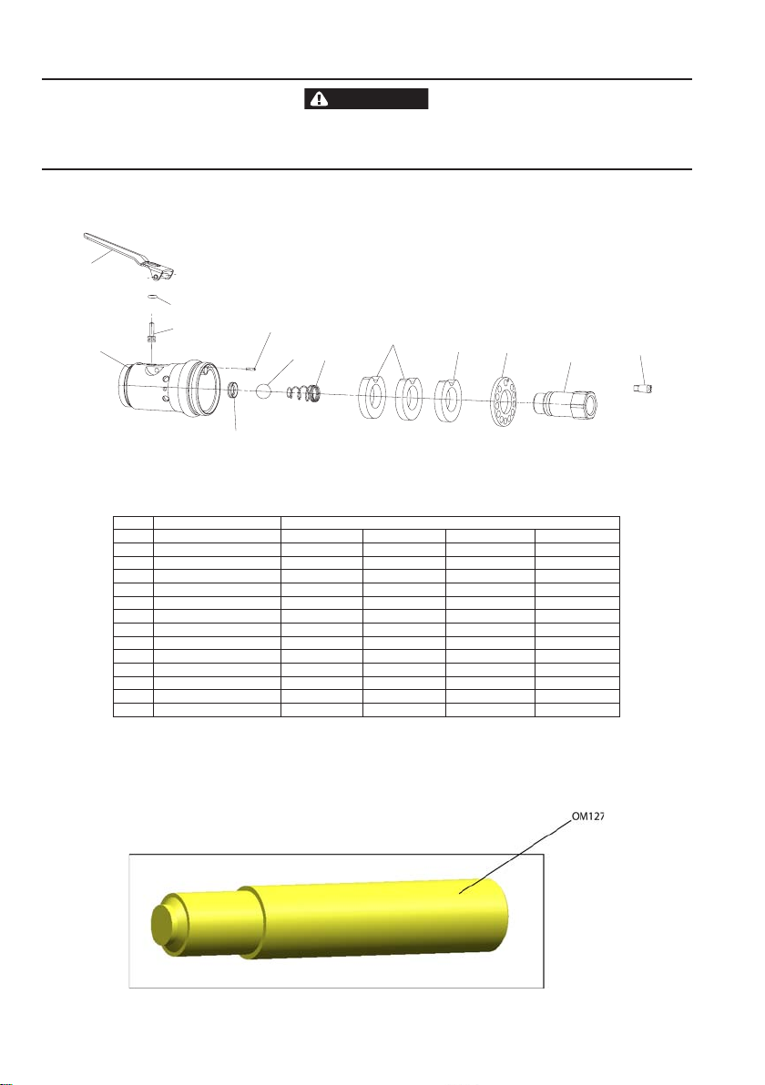
Throttle Housing
(Dwg. RG_80223480)
Throttle Housing Module
Item Part Description Part Number
Throttle Housing Module QA6-NPT-A231 QA6-BSP-A231 QA8-NPT-A231 QA8-BSP-A231
1 Throttle Housing
2 Ball Seat 12 mm
3 Throttle Pin
4 O-Ring 3.4 mm
5 Ball 12 mm
6 Ball Spring
7 Muer Black QA8-311 (1) QA8-311 (1) QA8-311 (2) QA8-311 (2)
8 Muer White QA6-311 (2) QA6-311 (2)
9 Diuser Plate
10 Pin 2 mm
11 Chip Holder Assembly QA4-A528 QA4-A528 QA4-A528 QA4-A528
12 Inlet Bushing Assembly QA6-NPT-A465 QA6-BSP-A465 QA6-NPT-A465 QA6-BSP-A465
13 Lever Assembly QA6-A93 QA6-A93 QA6-A93 QA6-A93
Tooling Required
Specic Tooling
Ball Seat Assembly tool (OM127): This tool Is Required to Press Ball Seat (2) Into Throttle Housing (1).•
Page 3
Standard tools and Products
O-Ring 11 mm
Inlet Bushing
Screen
O-ring Lube (Ingersoll Rand No. 68)
•
Vice
•
Needle Nose Pliers
•
Spanner Wrench
•
torque Wrench
•
Punch
•
Hammer
•
Subassemblies
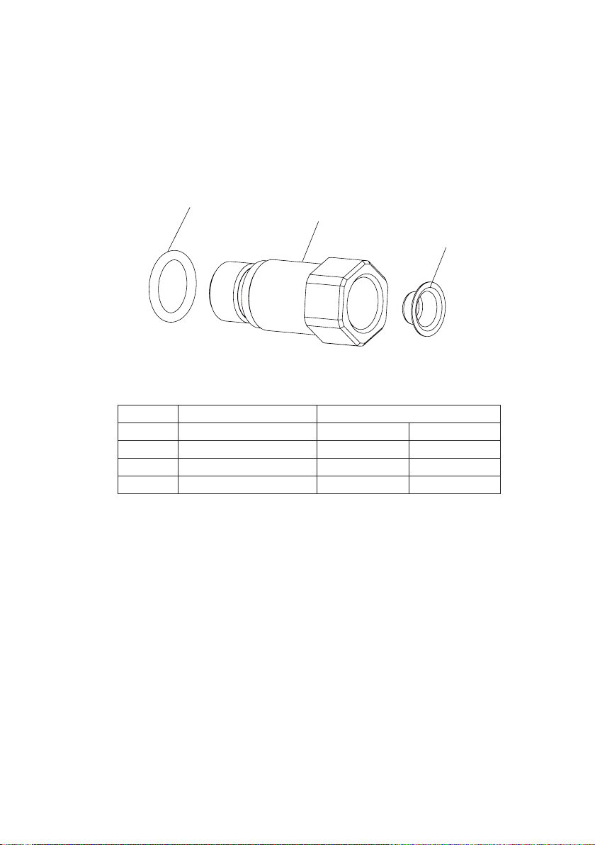
Inlet Bushing Assembly Exploded View
(Dwg. RG_45504578)
Inlet Bushing Assembly Parts List
Item Part Description Part Number
12 Inlet Bushing Assembly QA6-NPT-A465 QA6-BSP-A465
12A Inlet Bushing Assembly
12B O-Ring 11 mm
12C Screen
16601056_ed1 3
Page 4
4 16601056_ed1
Inlet Bushing Assembly Instructions
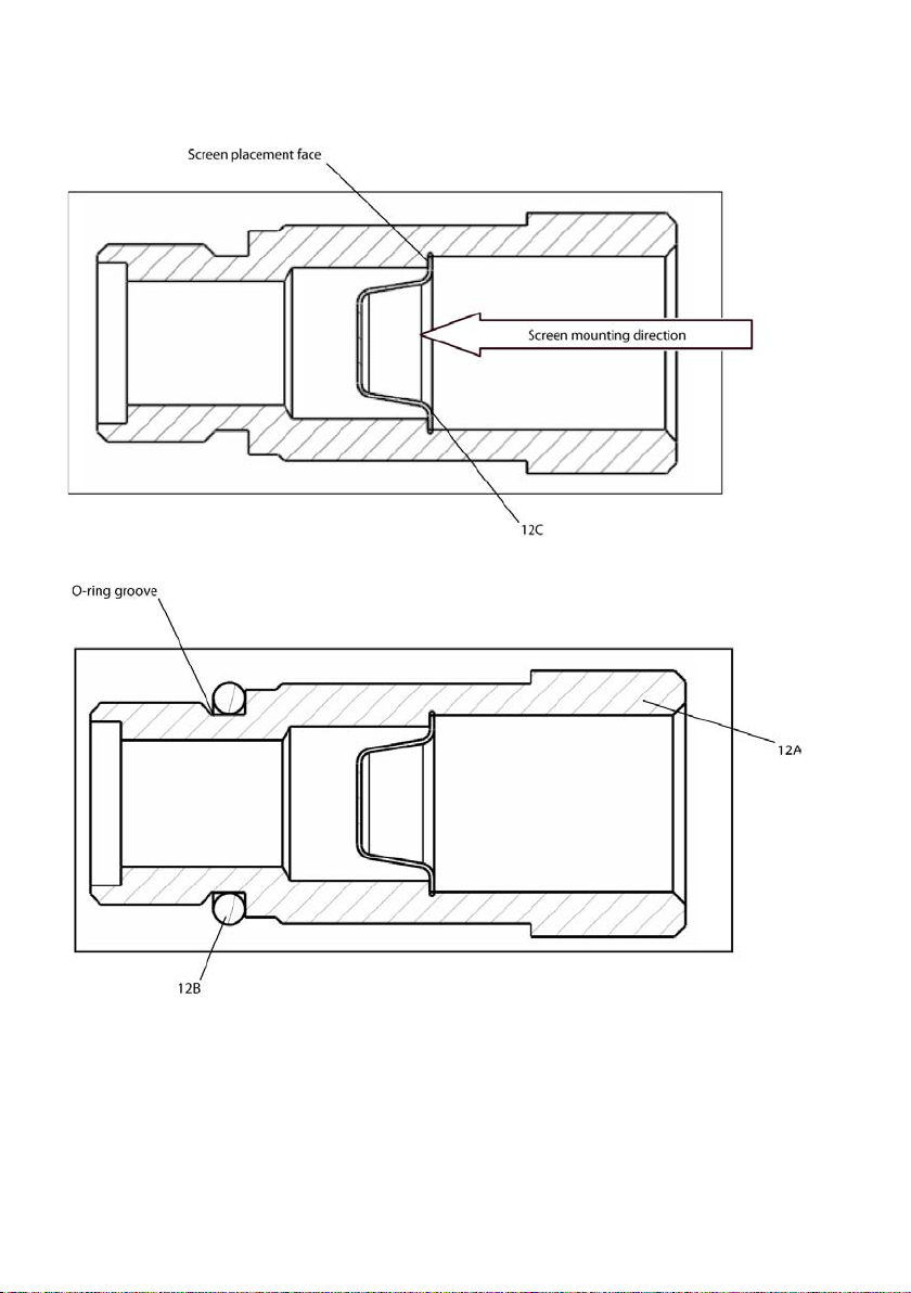
Mount screen (12C) into inlet bushing (12A) screen placement face. See section view for the proper placement.
1.
2. Coat o-ring (12B) with o-ring lube and mount on inlet bushing (12A) O-ring groove. See section view for the proper placement.
Page 5
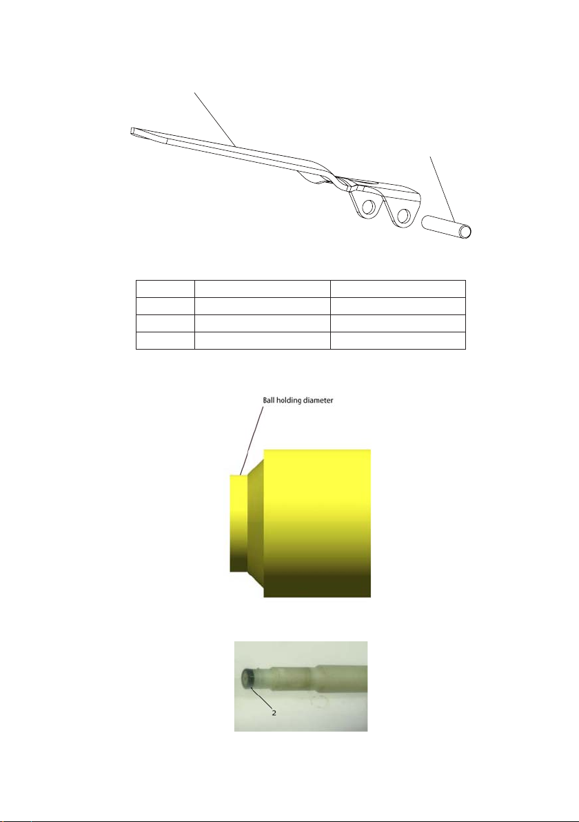
Lever Assembly Exploded View
Lever
Pin 3.5 mm
(Dwg. RG_45504586)
Lever Assembly Parts List
Item Part Description Part Number
13 Lever QA6-A93
13A Lever
13B Pin 3.5 mm
Throttle Housing Module Assembly Instructions
Coat Ball Seat holding diameter of tool (OM127) with O-ring Grease.
1.
2. Hold Ball Seat (2) on Ball Seat Assembly tool (OM127) as shown in picture below.
16601056_ed1 5
Page 6
6 16601056_ed1
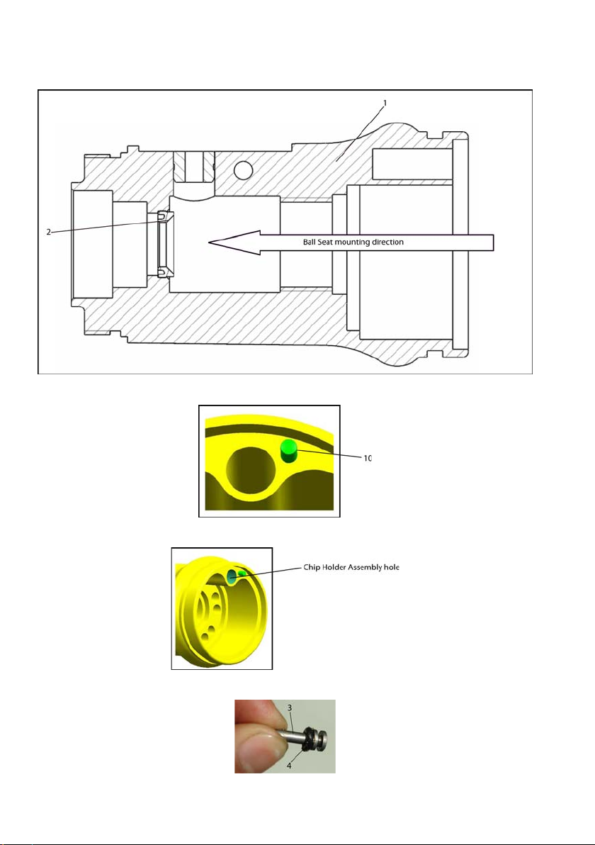
3. Press Ball Seat (2) with Ball Seat Assembly tool into Throttle Housing by using manual press. See Section view for the proper placement.
4. Insert pin (10) into pin hole in throttle housing and press to full depth by manual press, or hammer and punch.
5. Put chip holder assembly (11) into Chip holder assembly hole in throttle housing (1) so that leads are showing.
6. Coat O-ring (4) with O-ring lube and place over Throttle Pin (3).
Page 7
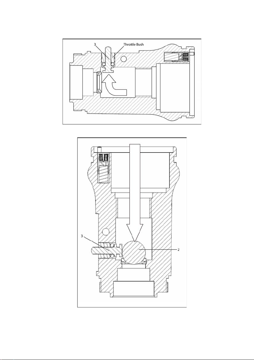
7. Install throttle pin (3) with O-ring in throttle housing (1) using needle nose pliers. Adjust to get throttle pin into throttle bush. Throttle pin
must be visible from outside over throttle housing bush area.
8. Insert ball (5) in Throttle Housing (1). Make sure, ball sits under Throttle Pin (3).
16601056_ed1 7
Page 8
8 16601056_ed1
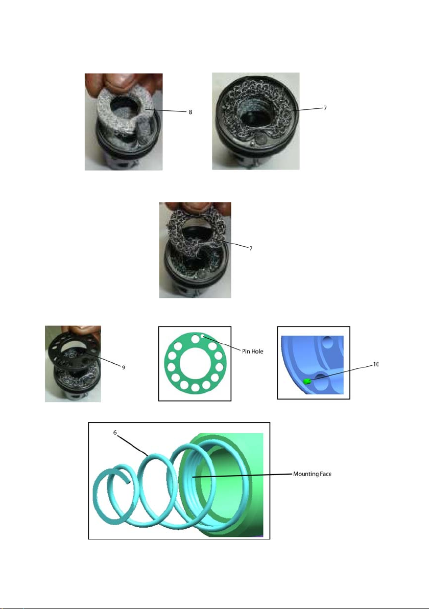
9. for QA6
Note: Muer (7) must face Input of tool.
Place Muer (8), Qty # 2 and Muer (7), Qty # 1 in the Throttle Housing (1). Align Muers to match Throttle Housing Prole.
For QA8
Place Muer (7), Qty # 2 in the Throttle Housing (1). Align Muers to match Throttle Housing prole.
10. Place Diuser Plate (9) on Throttle Housing. Align Pin (10) in Throttle Housing with Diuser Plate Pin Hole.
11. Grease Ball Spring (6) Ground Face and Mount on Inlet Bushing Assembly (12) Mounting Face.
Page 9
12. Align Ball Spring above Ball (5) and Thread into Throttle Housing (1).
7
3
4
5
6
1
8
10
2
9
13. Align Ball Spring above Ball (5) and Thread into Throttle Housing (1).
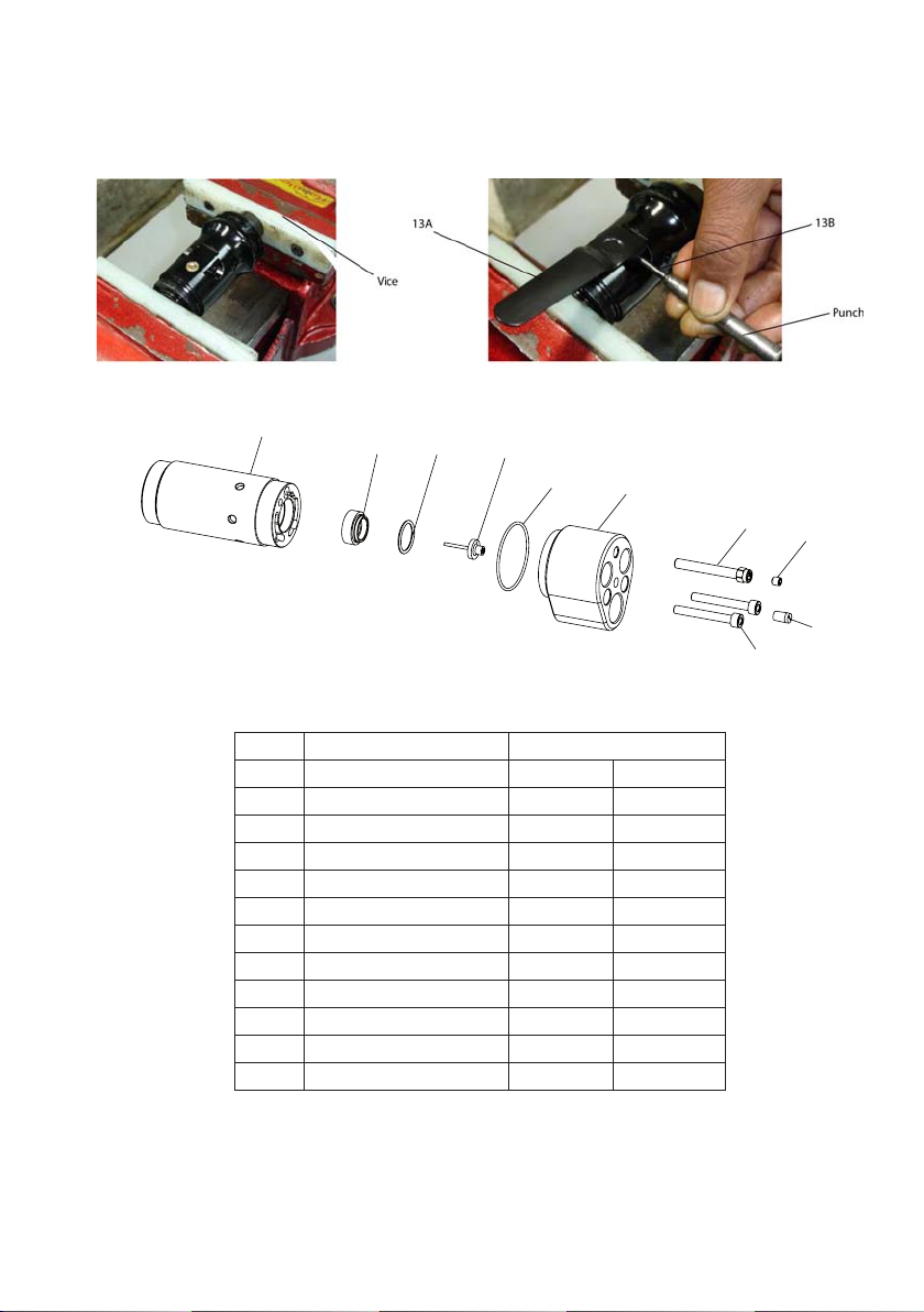
14. Hold Throttle Housing on vice. Place Lever (13a) over Throttle Housing and Assemble Pin (13b) using a Punch and Hammer.
Remote Housing Module Exploded View
(Dwg. RG_45500816)
Remote Housing Module Parts List
Item Part Description Part Number
Remote Housing Assembly QA6-R-A40 QA8-R-A40
1 Remote Start Housing
2 Chip Holder Assembly QA4-A528 QA4-A528
3 Valve Seat
* Remote housing Tune Up kit QA6-1R-K40 QA8-1R-K40
4 O-Ring 15.6 mm
5 Shut o Valve 131128 131128
6 O-Ring 40 mm
7 Remote Motor Housing
8 Remote Screw M6 QA6-439 QA6-439
9 Screw M5 QA6-439-1 (2) QA6-439-1 (2)
10 Set Screw M5
16601056_ed1 9
Page 10
10 16601056_ed1
Tooling Required
4
5
6
Standard tools and Products:
Ingersoll Rand # 68 Grease
•
torque Wrench
•
Subassemblies
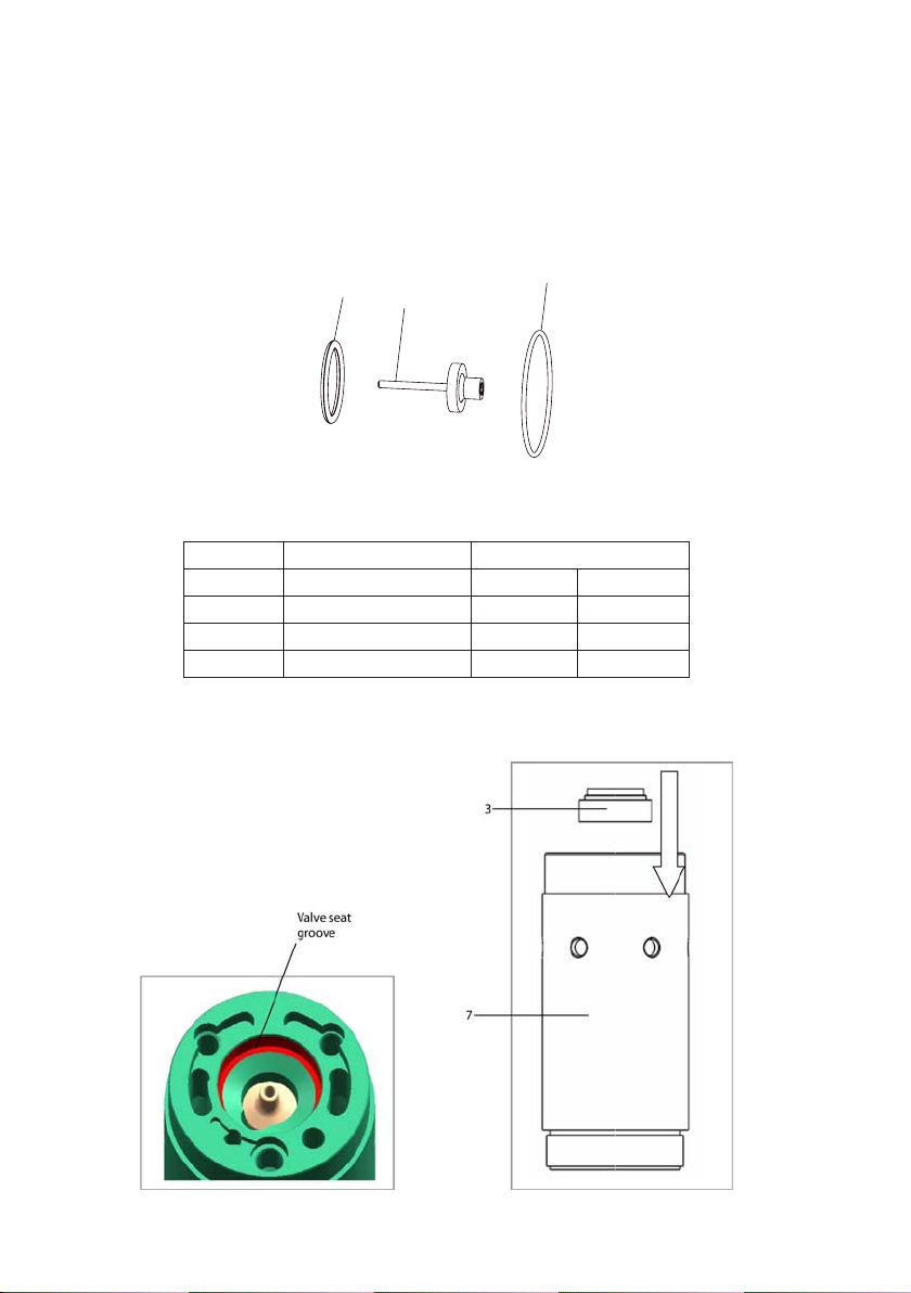
Remote Housing Tune Up Kit Exploded View
(Dwg. RG_45513520)
Remote Housing Tune Up Kit Parts List
Item Part Description Part Description
Remote housing Tune Up kit QA6-1R-K40 QA8-1R-K40
4 O-Ring 15.6 mm
5 Shut o Valve 131128 131128
6 O-Ring 40 mm
Assembly Instructions for Remote Housing Module
Place Valve Seat (3) in remote Motor Housing’s (7) valve seat groove.
1.
Page 11
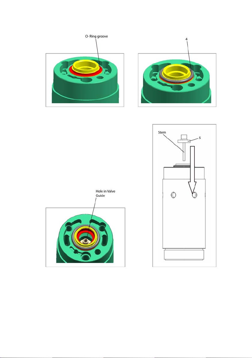
2. Grease O-ring (4) with Ingersoll Rand # 68 Grease and Mount on the Valve Seat’s (3) O-ring Groove in above Assembly.
3. Place Shut-o Valve (5) on Valve Seat’s (3) Step Diameter. Make Sure That Stem of Shut-o Valve Passes Through The Hole In Valve Guide In
Remote Motor Housing.
16601056_ed1 11
Page 12
12 16601056_ed1
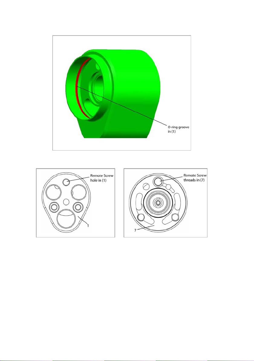
4. Grease O-ring (6) with Ingersoll Rand # 68 Grease and Mount in Remote Start Housing (1) Internal Groove.
5. Insert Remote Screw (8) in the Remote Screw Hole of Remote Housing. Slide this Assembly onto Remote Motor Housing (7). Tighten this
Screw onto Remote Screw’s threads in Remote Motor Housing by hand rst.
Page 13
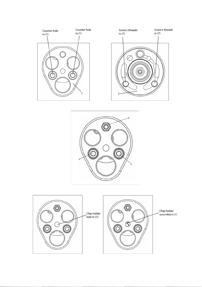
6. Insert Screw (9), Qty 2 in the counter holes in remote start housing of above assembly and tighten screws onto screw’s threads in remote
motor housing by hand rst.
7. Tight screw (8) clockwise to 5 nm (3.7 Ft-lb) and screws (9) clockwise to 6 nm (4.5 Ft-lb) assembled in step 5 and 6 by using a torque wrench.
8. Insert Chip Holder Assembly (2) into the chip holder hole in remote start housing (1).
16601056_ed1 13
Page 14
14 16601056_ed1
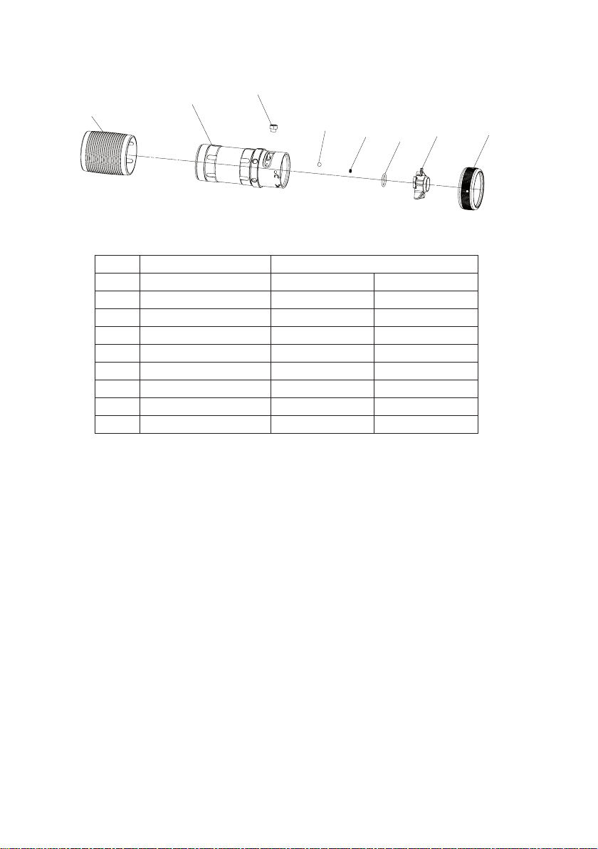
Motor Housing Module Exploded View
2
1
8
6
5
4
3
7
(Dwg. RG_45504602)
Motor Housing Module Parts List
Item Part Description Part Number
Motor Housing Assembly QA6-A40 QA8-A40
1 M otor Housing
2 Grip QA6-145 QA6-145
3 Reverse Valve QA6-329 QA6-329
4 O-Ring 14.8 mm
5 Spring 3.6 mm
6 Ball
7* Reverse Ring Assembly QA6-A273 QA6-A273
8 Reverse Screw M8 131069 131069
* See Subassembly Exploded View and Parts List for Detail.
Tooling Required
Standard tools and Products
O-ring Lube ( Ingersoll Rand # 68)
•
Loctite # 542
•
Allen Key 4mm
•
Page 15
Subassemblies
7A
7A
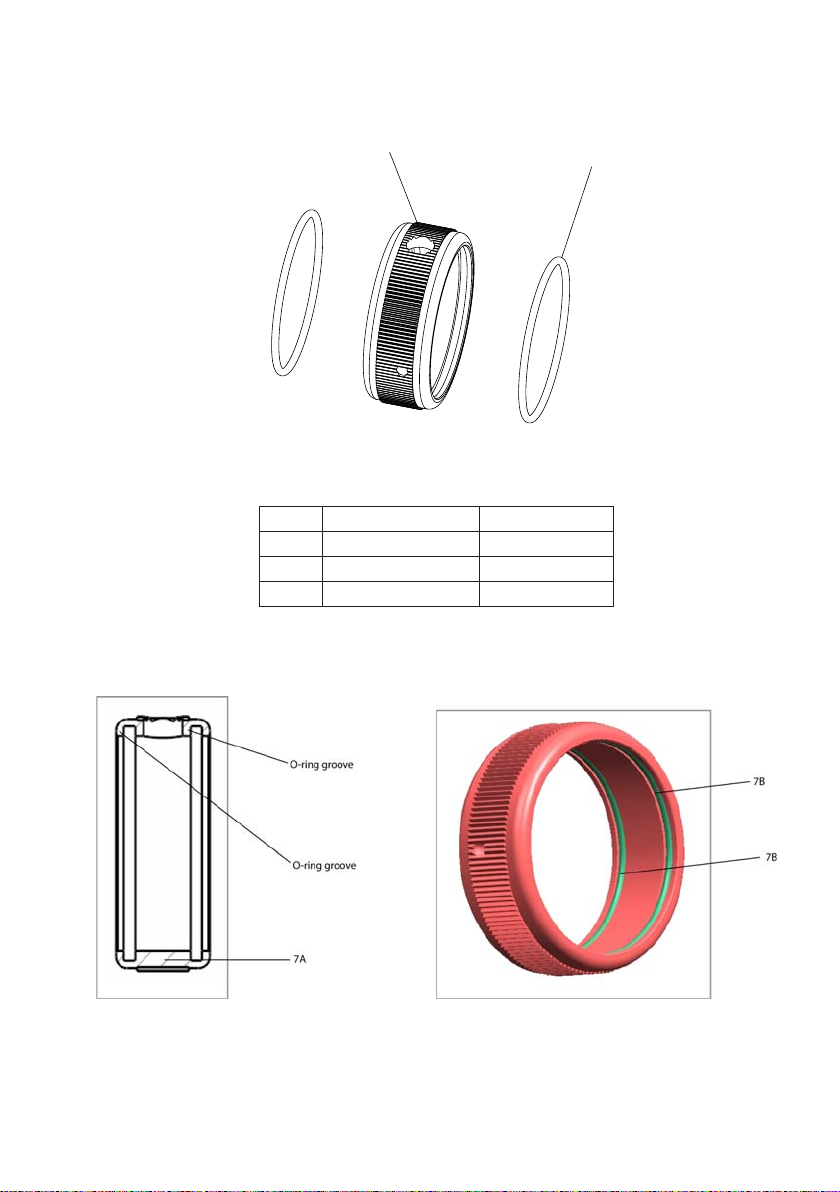
Reverse Ring Assembly Exploded View
(Dwg. RG_45503844)
Reverse Ring Assembly Parts List
Item Part Description Part Number
7 Reverse Ring Assembly QA6-A273
7A Reverse Ring
7B O-ring 38 mm (2)
Assembly Instructions for Reverse Ring Assembly
Coat O-ring (7b), Qty#2 with O-ring lube and mount in Reverse Ring (7a) grooves, one each. See section view for the proper placement.1.
16601056_ed1 15
Page 16
16 16601056_ed1
Assembly Instructions for Motor Housing Module
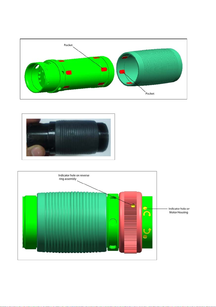
Slide Grip (2) on motor housing (1). Make sure to align motor housing pockets with grip pockets.
1.
Note: Do not use oil or other lubricants, heat slightly to soften the grip if required.
2. Orient Reverse Ring Assembly (7) with indicator hole closer to indicator hole on motor housing (1).
Page 17
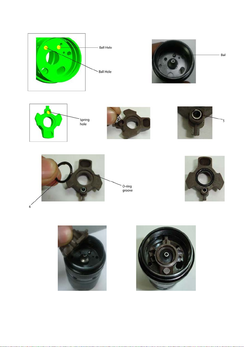
3. Coat Ball (6) with o-ring grease and place onto either ball hole in motor housing.
4. Coat Spring (5) with o-ring grease and place onto reverse valve (3) spring hole.
5. Coat O-ring (4) with o-ring lube and place on the groove in reverse valve (3).
6. Place above reverse valve assembly onto motor housing. Make sure that ball spring in reverse valve sits over ball placed in motor housing.
See Step 3 above.
16601056_ed1 17
Page 18
18 16601056_ed1
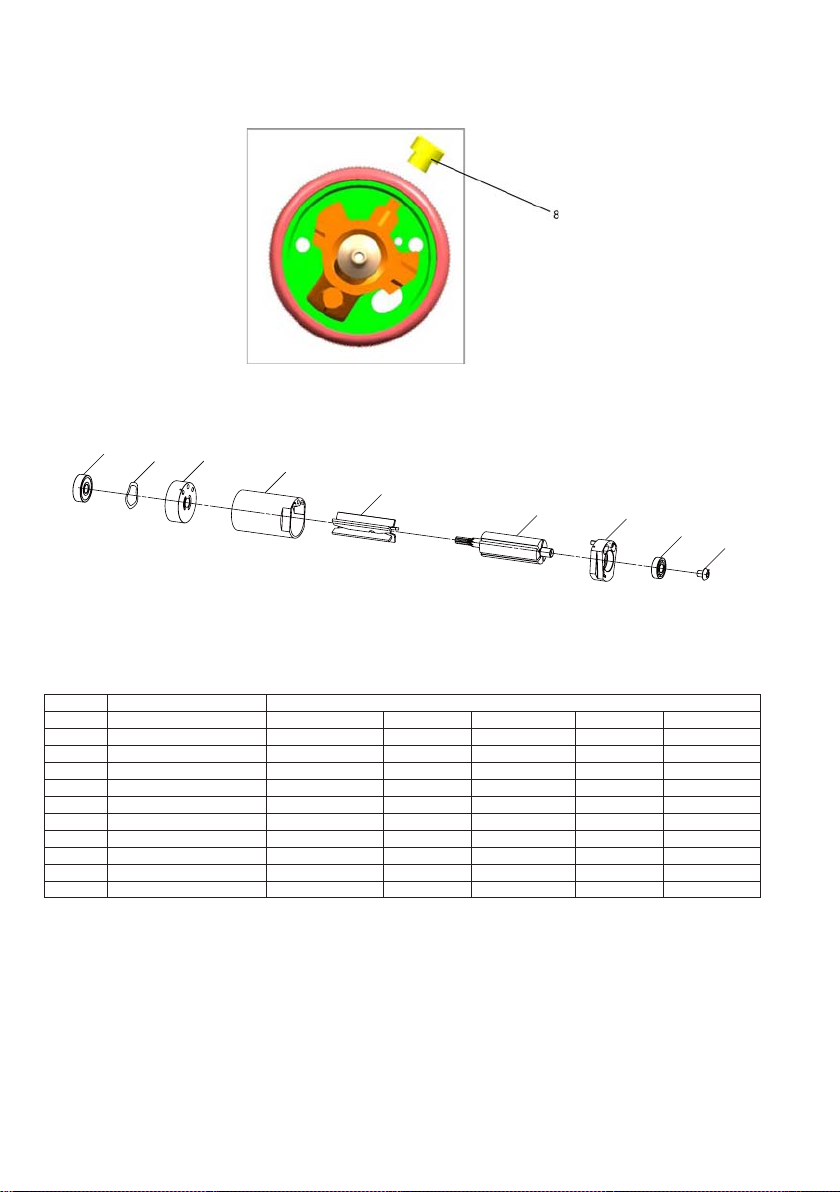
7. Coat Reverse Screw (8) Threads with loctite # 542. Tighten reverse screw fully with allen key on reverse ring assembly placed on motor
6
3
9
8
2
1
7
5
4
housing and then back o 1 / 4 turn. Make sure that screw sits over reverse valve edge. Remove the excess loctite.
Motor Module Exploded View
(Dwg. RG_80221583)
Motor Module Parts List
Item Part Description Part Number
1 Rotor QA6-53-8 QA6-53-10 QA6-53-11 QA8-53-10 QA8-53-11
2* Vane Pack QA6-42-5 QA6-42-5 QA6-42-5 QA8-42-5 QA8-42-5
* Motor Kit QA6-1-K53 QA6-1-K53 QA6-1-K53 QA6-1-K53 QA6-1-K53
3 Wave Washer
4 Adjustment Screw M5
5 Rear End Bearing 17x7x5
6 Front End Bearing 22x7x7
7* Rear Endplate Assembly QA6-A12 QA6-A12 QA6-A12 QA6-A12 QA6-A12
8* Cylinder Assembly QA6-A3 QA6-A3 QA6-A3 QA8-A3 QA8-A3
9 Front Endplate QA6-11 QA6-11 QA6-11 QA6-11 QA6-11
* See Subassembly Exploded View & Parts List for Detail.
Motor Assembly QA6-A53-8 QA6-A53-10 QA6-A53-11 QA8-A53-10 QA8-A53-11
Page 19
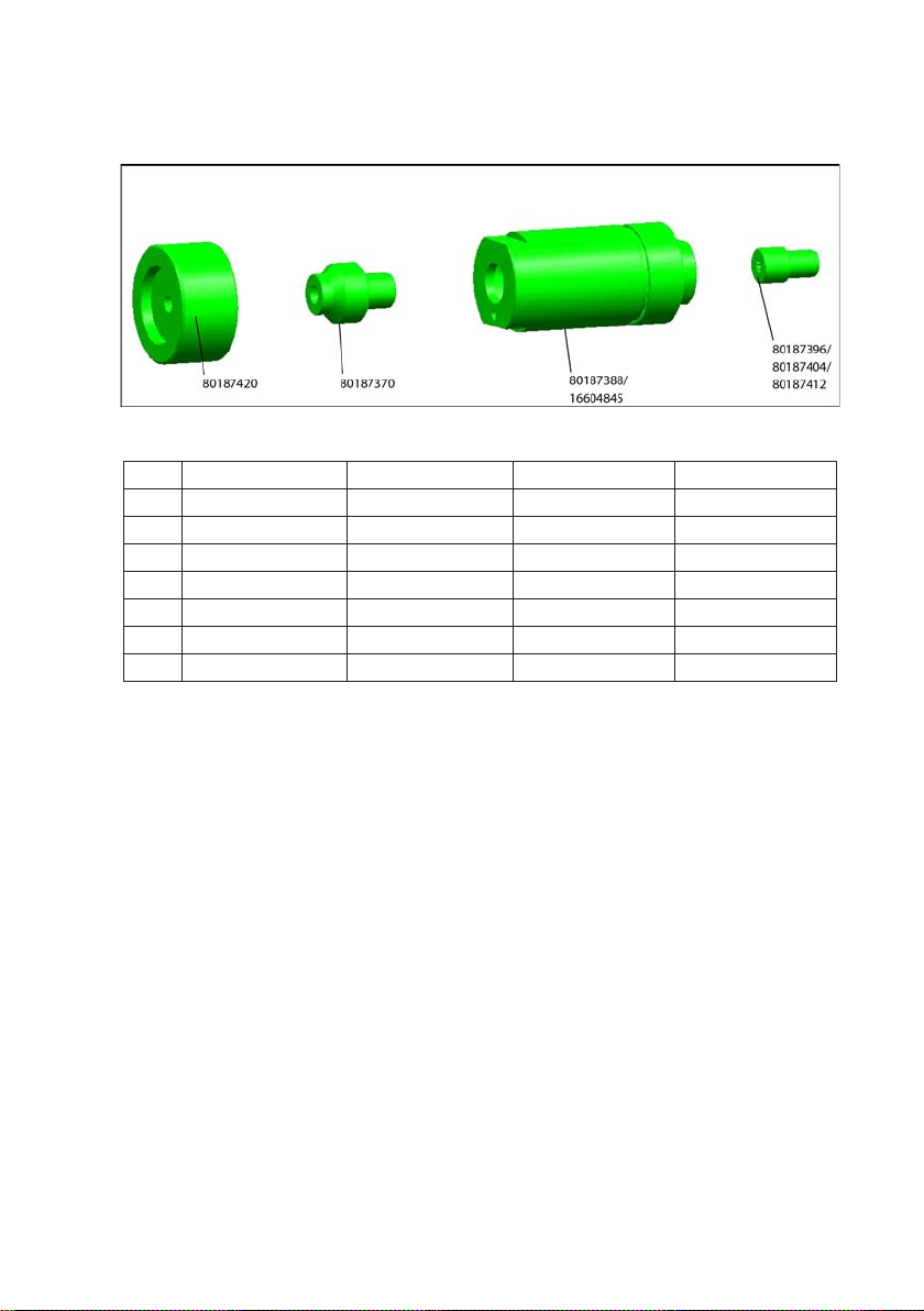
Tooling Required
Specic Tooling Exploded View
Specic Tooling Parts Lists
Item Part Description Part Number Usage For Model
1 Rotor Spline Adaptor 80187396 8 Teeth Motor spacing QA6 { }
2 Rotor Spline Adaptor 80187404 10 Teeth Motor spacing QA6 { }, QA8 { }
3 Rotor Spline Adaptor 80187412 11 Teeth Motor spacing QA6 { }, QA8 { }
4 Motor Clamp tool 80187388 Motor spacing QA6 { }
5 Motor Clamp tool 16604845 Motor spacing QA8 { }
6 Motor Press Assembly 80187370 Motor Back Bearing Press QA6 { }, QA8 { }
7 Motor Assembly tool 80187420 Motor Back Bearing Press QA6 { }, QA8 { }
Standard tools and Products
Loctite # 243
•
Vice
•
3mm Hex Key
•
Ingersoll Rand # 10 Oil
•
Ingersoll Rand # 68 Grease
•
Heat Gun – for Disassembly
•
Soft Mallet
•
Manual Arbor Press
•
16601056_ed1 19
Page 20
20 16601056_ed1
Subassemblies
2A
6
3
5
4
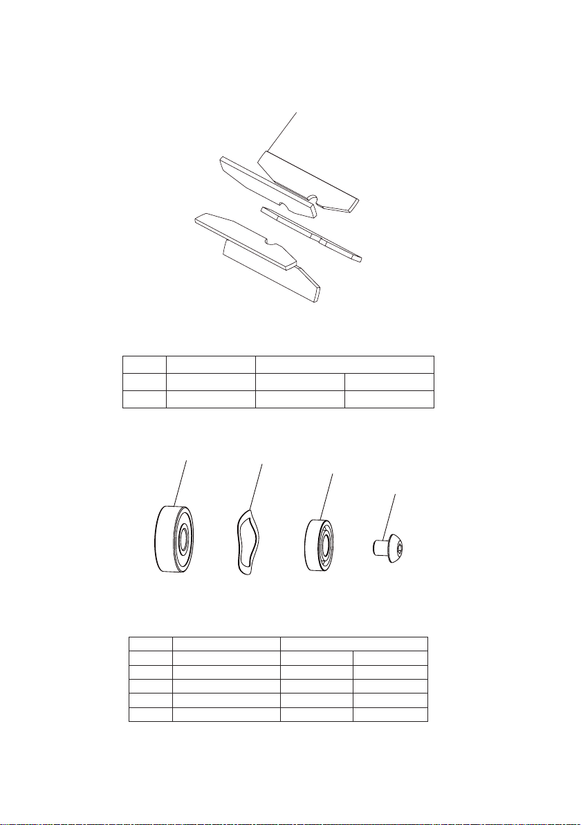
Vane Pack Exploded View
(Dwg. RG_45492162)
Vane Pack Parts List
Motor Kit Exploded View
Item Part Description Part Number
2 Vane Pack QA6-42-5 QA8-42-5
2A Vane (5) (5)
(Dwg. RG_45513546)
Motor Kit Parts List
Item Part Description Part Number
* Motor Kit QA6-1-K53 QA6-1-K53
3 Wave Washer
4 Adjustment Screw M5
5 Rear End Bearing 17x7x5
6 Front End Bearing 22x7x7
Page 21

Rear Endplate Assembly Exploded View
7A
7B
(Dwg. RG_80238579)
Rear Endplate Assembly Parts List
Item Part Description Part Number
7 Rear Endplate Assembly QA6-A12
7A Rear Endplate
7B Roll Pin 19 mm Y178-41
Assembly Instructions for Rear Endplate Assembly
Insert Roll Pin (7B) in rear endplate (7A) hole and press to maintain pin projection of 2.5Mm. See views below for the proper placement.1.
16601056_ed1 21
Page 22
22 16601056_ed1
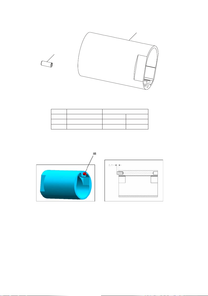
Cylinder Assembly Exploded View
8B
8A
(Dwg. RG_45492139)
Cylinder Assembly Parts List
Item Part Description Part Number
8 Cylinder Assembly QA6-A3 QA8-A3
8A Cylinder
8B Roll Pin Y178-191 Y178-191
Assembly Instructions for Cylinder Assembly
Insert Roll Pin (8B) into Cylinder (8A) Pin Hole and Press Pin on Manual Press to Maintain Pin Projection of 2.5mm. See views below for the
1.
proper placement.
Page 23
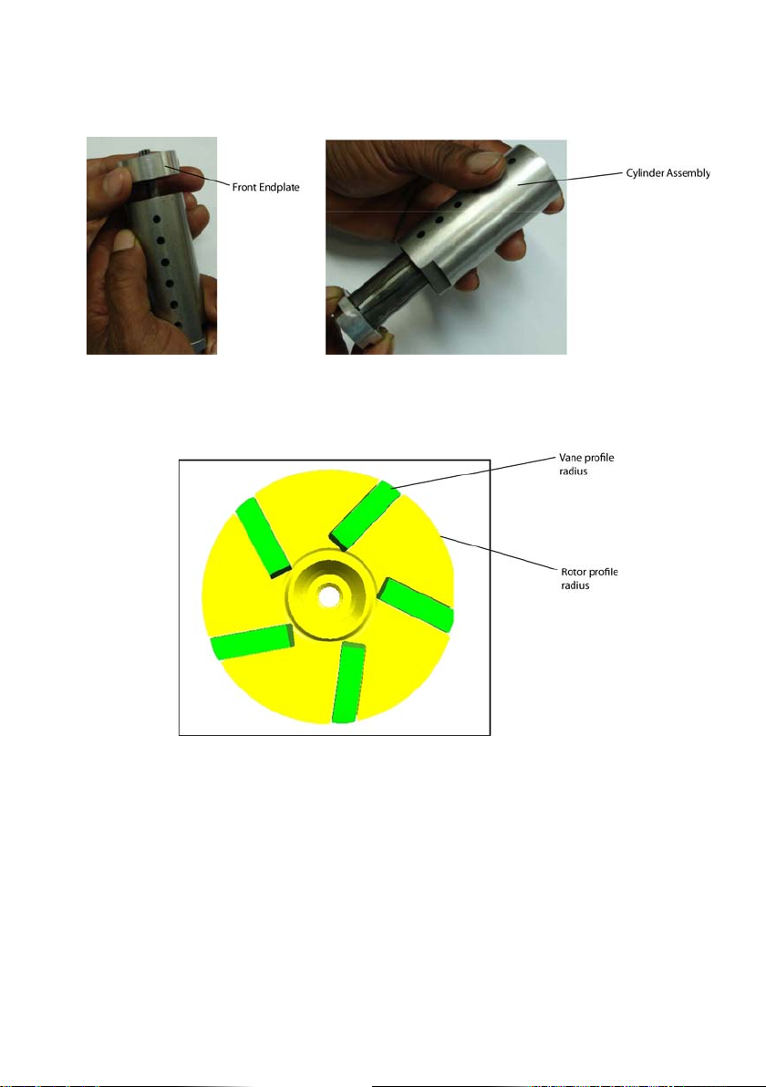
Replacement of Vanes
Hold Motor rmly in hand, strike mallet on rotor spline to drive rotor (1) and rear endplate assembly out of front endplate (9). Remove front
1.
endplate (with wave washer and bearing) and cylinder assembly from motor module.
2. Remove Vanes (2A) qty # 5 from rotor and using degreaser clean all surfaces of rotor and endplates. Make sure not to get degreaser in
bearing or it may be damaged.
3. Oil all surfaces of new vanes (qty # 5) with ingersoll rand # 10 oil. Place them one at a time in rotor (1) slots. Make sure to match vane prole
radius with rotor prole radius. See view below.
Note: Motor will run without lubrication but oil is used for maximum vane life.
16601056_ed1 23
Page 24
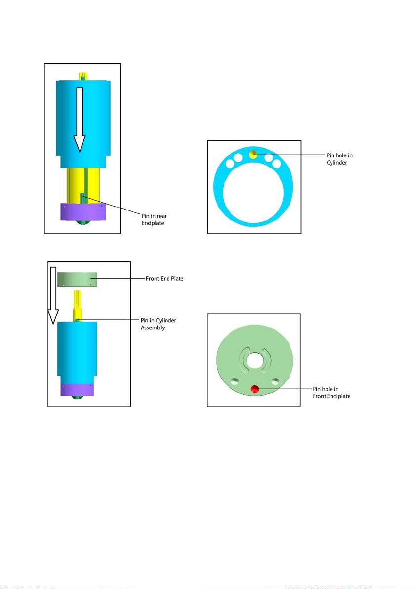
24 16601056_ed1
4. Mount Cylinder Assembly in above assembly. Align pin in rear endplate with pin hole in cylinder assembly.
Note: Hold assembly in straight upward direction otherwise vanes will walk out.
5. Place Front Endplate (with Wave Washer and Bearing) assembly onto rotor shaft. Align roll pin (8b) in cylinder assembly with pin hole in
front endplate.
Page 25
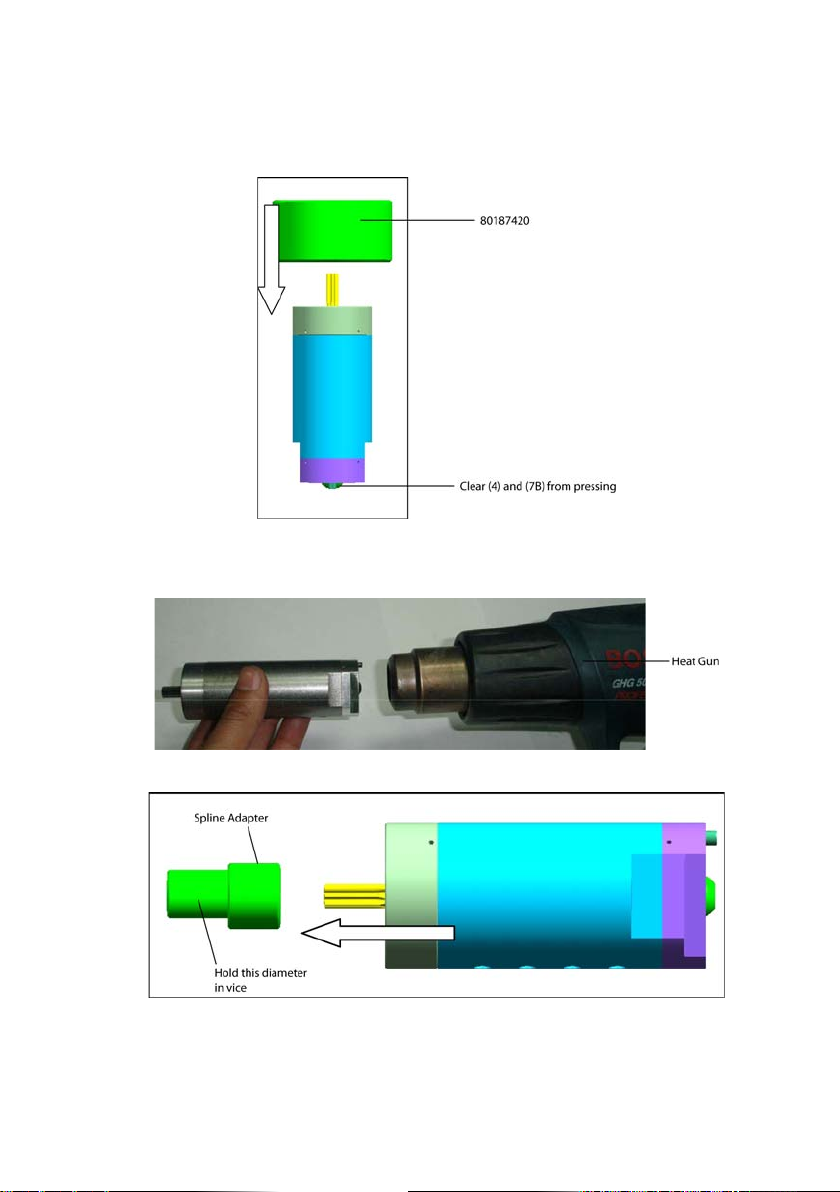
6. Place Fixture 80187420 on top of motor, then press until bearing (6) is properly spaced.
Notes:
1. Make sure to clear adjustment screw (4) and roll pin (7b) in rear endplate assembly from pressing.
2. Bearing should be pressed at least 0.025mm below the surface of the end plate, and not exceeding 0.2mm. The front bearing press
xture 80187420 provides this spacing.
Disassembly of Motor Module
Heat Adjustment Screw (4) screwed in the rear of motor with heat gun.
1.
Note: Adjustment Screw has loctite. Heat is used to break that bonding.
2. Hold Spline Adaptor in vice. Insert rotor splines into adaptor’s (80187396 / 80187404 / 80187412 depending on rotor teeth) spline.
16601056_ed1 25
Page 26
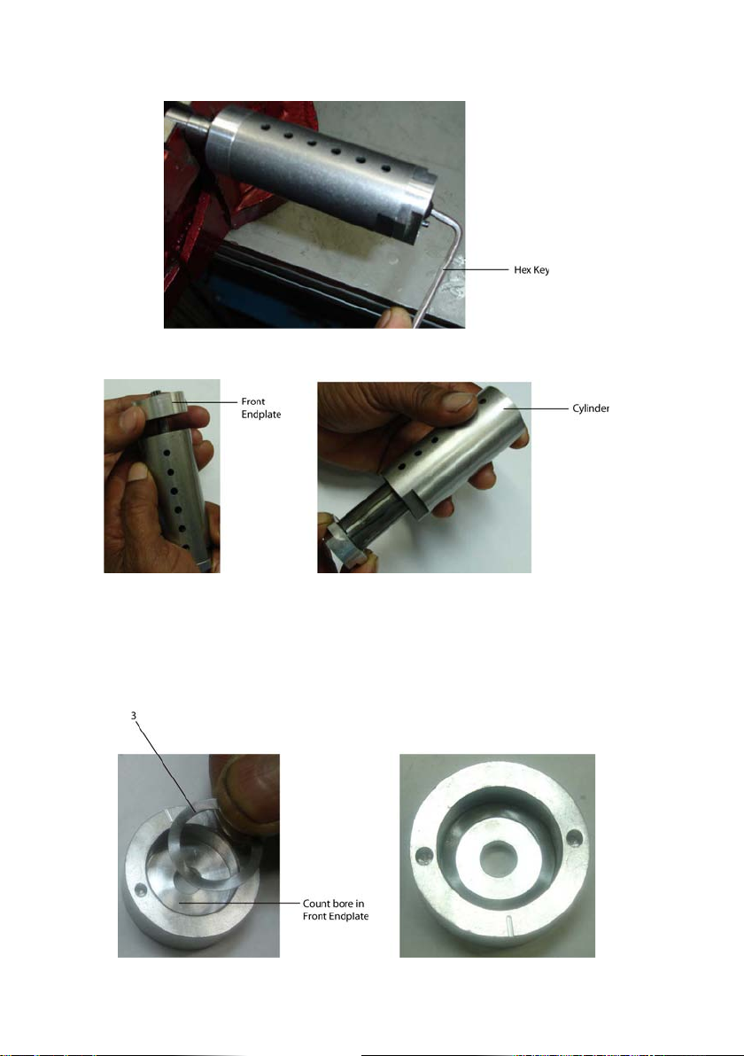
26 16601056_ed1
3. Using 3mm Hex key, unscrew adjusting screw.
4. Hold Motor rmly in hand, strike mallet on rotor spline to drive rotor (1) and rear endplate assembly out of front endplate (9). Remove front
endplate (with wave washer and bearing) and cylinder assembly from motor module.
5. Remove Vanes (2A) Qty # 5 from rotor and using degreaser clean all surfaces of rotor and endplate.
6. Remove rear endplate assembly (7) from rotor.
Note: It is not a hard press, so gently press out rotor with a pin<7mm from endplate.
Assembly Instructions for Motor Module
Note: Replacement of motor parts may change shut o operation of tool. We recommend ordering new pushrod (132017).
1. Completely clean rotor and cylinder with a degreaser agent, it may be necessary to use a light brush to clean rotor and pin with degreaser.
2. Place Wave washer (3) in front end plate (9) counter bore.
Page 27
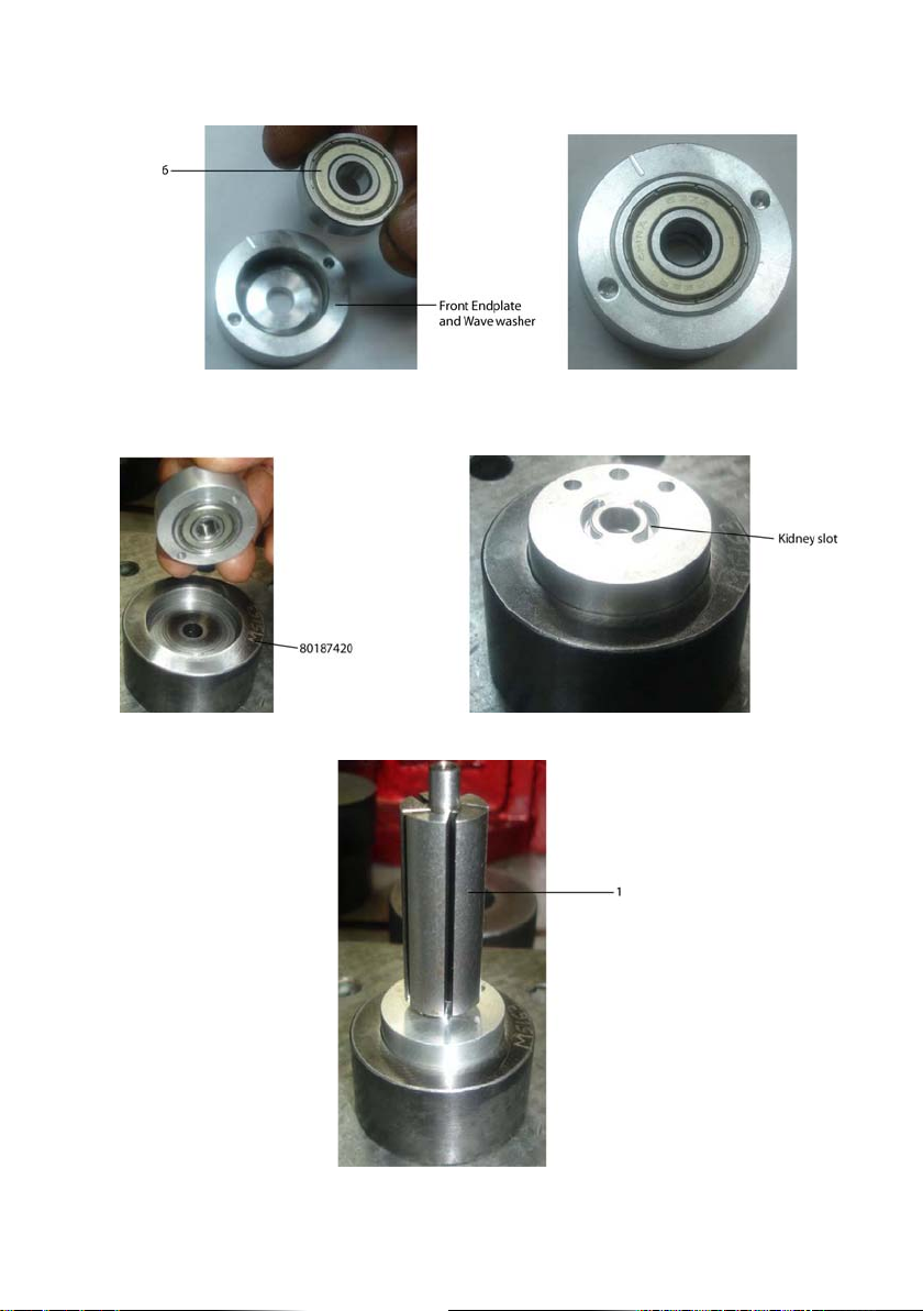
3. Place Bearing (6) over wave washer in front endplate counter bore.
4. Place above assembly in the counter bore of xture 80187420. Kidney slot side of front endplate must be upward.
Note: Fixture provides proper placement of front endplate and bearing. Bearing must be pressed a minimum of 0.025mm below front
endplate surface after nal motor spacing adjustment. Heat build up and bearing failure may occur if not properly spaced.
5. Place Rotor onto front endplate bore. Hold xture 80187370 in manual press and press rotor in front endplate.
16601056_ed1 27
Page 28
28 16601056_ed1
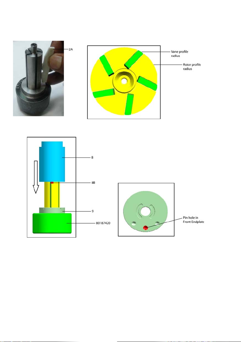
6. Oil all surfaces of new vanes (Qty # 5) with Ingersoll Rand # 10 oil. Place them one at a time in rotor (1). Make sure to match vane prole
radius with prole radius of rotor.
Note: Motor will run without lubrication but oil is used for maximum vane life.
7. Slide Cylinder Assembly (8) over rotor and front endplate. Align roll pin (8b) in cylinder assembly with front endplate pin hole.
Note: Hold Assembly in straight upward direction otherwise vanes will walk out.
Page 29

8. Put Rear Endplate Assembly onto rotor shaft. Align roll pin (7B) in rear endplate assembly with cylinder pin hole.
Note: Counter Bore side of rear endplate assembly must be upward.
9. Grease Bearing (5) with Ingersoll Rand # 68 Grease and place onto Rotor Shaft and Rear Endplate Assembly counter Bore. Press Bearing
Using Fixture 80187370 Until Assembly is tight and will not rotate.
Note: Rear Endplate press xture 80187370 presses the bearing inner race. Pressing outer race may damage bearing.
16601056_ed1 29
Page 30
30 16601056_ed1
Adjustment of Motor Module
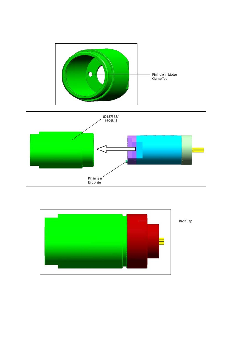
Place Motor in motor clamp tool xture 80187388 / 16604845 (Depending on QA6 or QA8). Align Motor Assembly so that the pin (7B) in rear
1.
endplate assembly locates into pin hole at the bottom of xture.
2. Thread Back Cap onto xture. Tighten it to 40 nm (30 ft-lb) using a wrench.
Note: Motor clamp tool xture simulates motor in actual tool assembly. Unclamped motors may not be properly spaced and cause motor to
overheat or bind.
Page 31
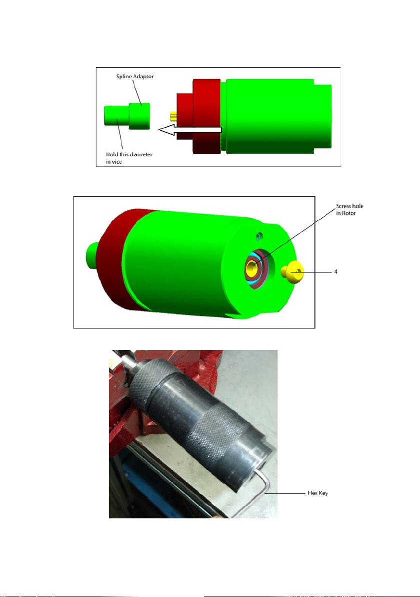
3. Hold Spline adaptor in vice. Insert rotor splines of above assembly into spline adaptor (80187396 / 80187404 / 80187412 depending on
rotor teeth) splines.
4. Clean Adjustment screw (4) and screw hole in back of rotor with degreaser. Coat initial few threads of adjustment screw with Loctite # 243.
Partially thread adjustment screw into the screw hole of rotor using 3mm hex key.
5. Slowly tighten Adjustment Screw. Tighten it until Assembly rotates freely.
Remove Motor module from Motor Clamp Fixture 80187388 / 16604845.
16601056_ed1 31
Page 32
32 16601056_ed1
Note: When spacing is correct and motor is rotating freely, motor and xture 80187388 / 16604845 should fall to vertical orientation of pin and
4
2
3
5
1
6
center screw, if motor does not come free and screw can not be tightened further, motor must be completely disassembled.
Note: After Motor is clamped in 80187388 / 16604845 tooling, the rotor may already spin freely. If this occurs, follow the same assembly
procedure procedure, after the screw (bottom out against back bearing), continue tightening about 10 degrees. Rotor should still spin freely.
This is to ensure proper rotor spacing during normal tool operation.
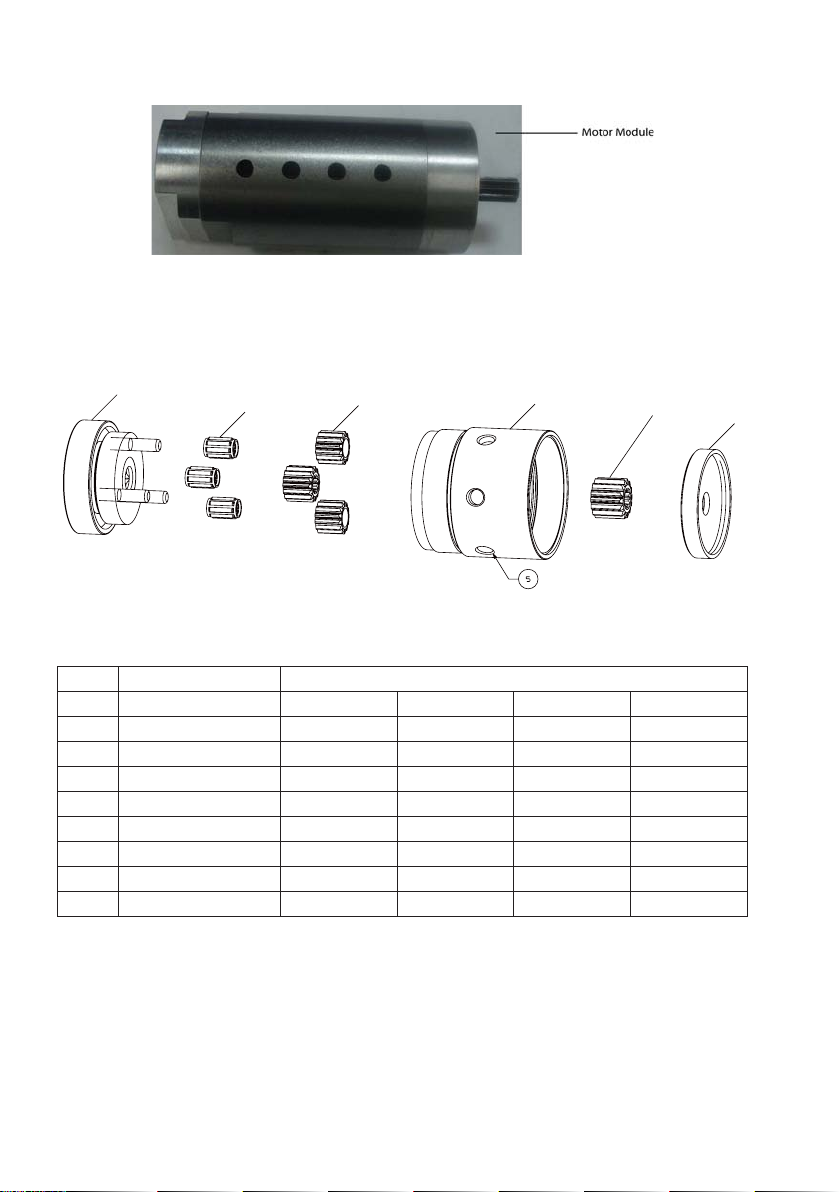
First Stage Module Exploded View
(Dwg. RG_53449310)
First Stage Module Parts List
Item Part Description Part Number
1st Stage Gear Assembly 132023 132022 132020 132021
1 Front Cap 132004 132004 132004 132004
2* Needle Roller Bearing Kit QA6-1-K24 QA6-1-K24 QA6-1-K24 QA6-1-K24
3* Planet Gear Kit QA6-K10-29 QA6-K10-25 QA8-K10-29 QA8-K10-13
4 Spindle Assembly QA6-A8-9P50 QA6-A8-6P54 QA6-A8-7P80 QA8-A8-3P86
4A+ Bearing 37x20x9 119277 119277 119277 119277
4B+ Circlip 126293 126293 126293 126293
5 Gear Case 132011 132013 132011 132011
6 Pinion - - - QA6-17-14
+ Not Illustrated.
* See Subassembly Exploded View and Parts List for Detail.
Page 33
Tooling Required
2A
3A
Standard tools and Products
Ingersoll Rand # 90 Grease
•
External Circlip Pliers
•
Subassemblies
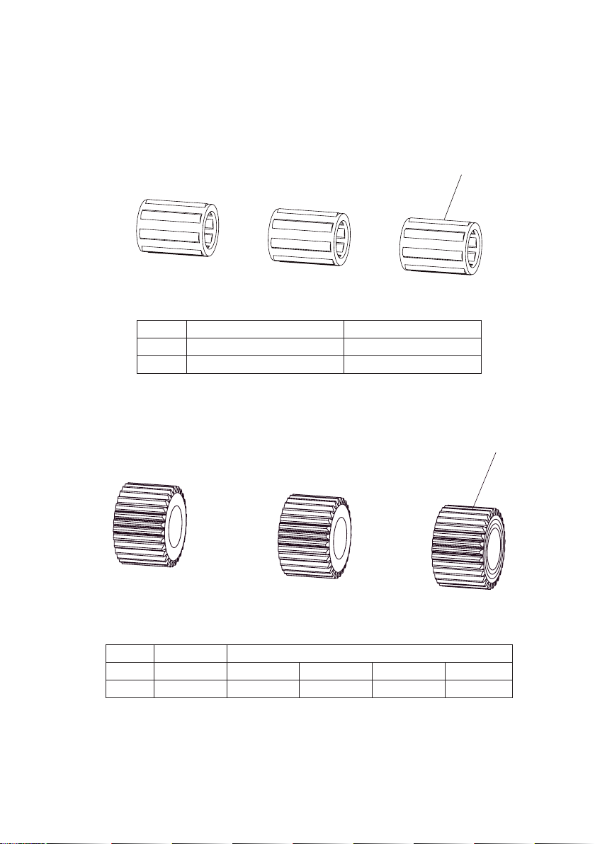
Needle Roller Bearing Kit Exploded View
(Dwg.RG_45513702)
Needle Roller Bearing Kit Parts List
Item Part Description Part Number
2 Needle Roller Bearing Kit QA6-1-K24
2A Needle R oller Bearing (3)
Planet Gear Kit
Note: If Planet teeth are broken, it is recommended to buy this kit for maximum tool life.
Planet Gear Kit Exploded View
(Dwg.RG_45513827)
Planet Gear Kit Parts List
Item Part Description Part Number
3 Planet Gear Kit QA6-K10-29 QA6-K10-25 QA8-K10-29 QA8-K10-13
3A Planet Gear (3) (3) (3) (3)
16601056_ed1 33
Page 34
34 16601056_ed1
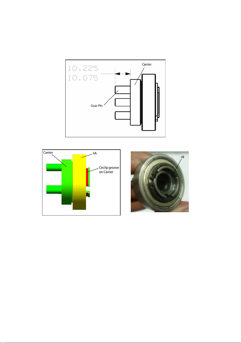
Assembly Instructions for Spindle Assembly
Press Bearing (4A) on Carrier Shaft of Spindle Assembly (4).
1.
Notes:
Support inner race of bearing during pressing.
a.
Unshielded Side of Bearing must face Spindle Assembly (4).
b.
The Gear Pins assembled with carrier of spindle assembly (4) must not press further during pressing the bearing. Otherwise, check pin
c.
projection of 10.225/10.075Mm from carrier face as shown in view below.
2. Use an External Circlip pliers to place circlip (4b) on the groove of carrier of above assembly.
Page 35
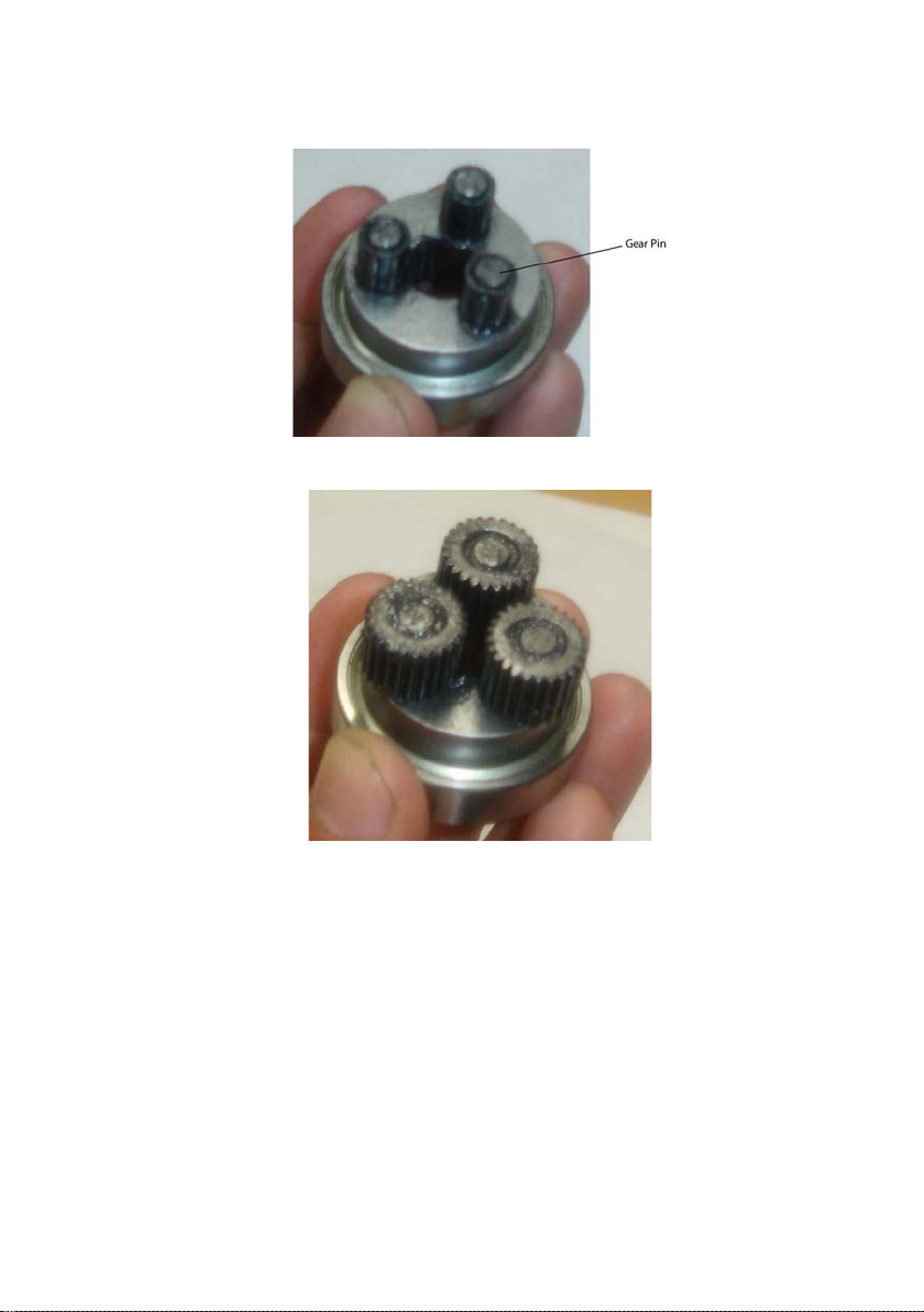
Assembly Instructions for First Stage
Grease Needle Roller Bearings (2a) with Ingersoll Rand #90 Grease. Place Needle Roller Bearing, Qty#3 onto Gear Pins of Carrier.
1.
2. Place Planet Gear, Qty # 3 onto Needle Roller Bearings of above Assembly.
16601056_ed1 35
Page 36
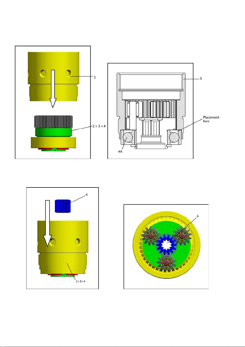
36 16601056_ed1
3. Grease Gear Case’s splines with ingersoll rand # 90 grease. Place above assembly in gear case (5).Ensure planet gear’s teeth engage with
gear case’s teeth and face of bearing in spindle assembly must sits against the placement face of gear case. See section view below for the
proper placement.
Note: Hold Assembly in straight upward direction otherwise planet gears and needle roller pins will walk out.
4. Grease Spindle Assembly’s (4) Gears with Ingersoll Rand # 90 Grease.
5. Note: (This is an additional Step for 132010 Assembly only)
Mount Pinion (6) in Planet Gears set in the above Assembly.
Page 37
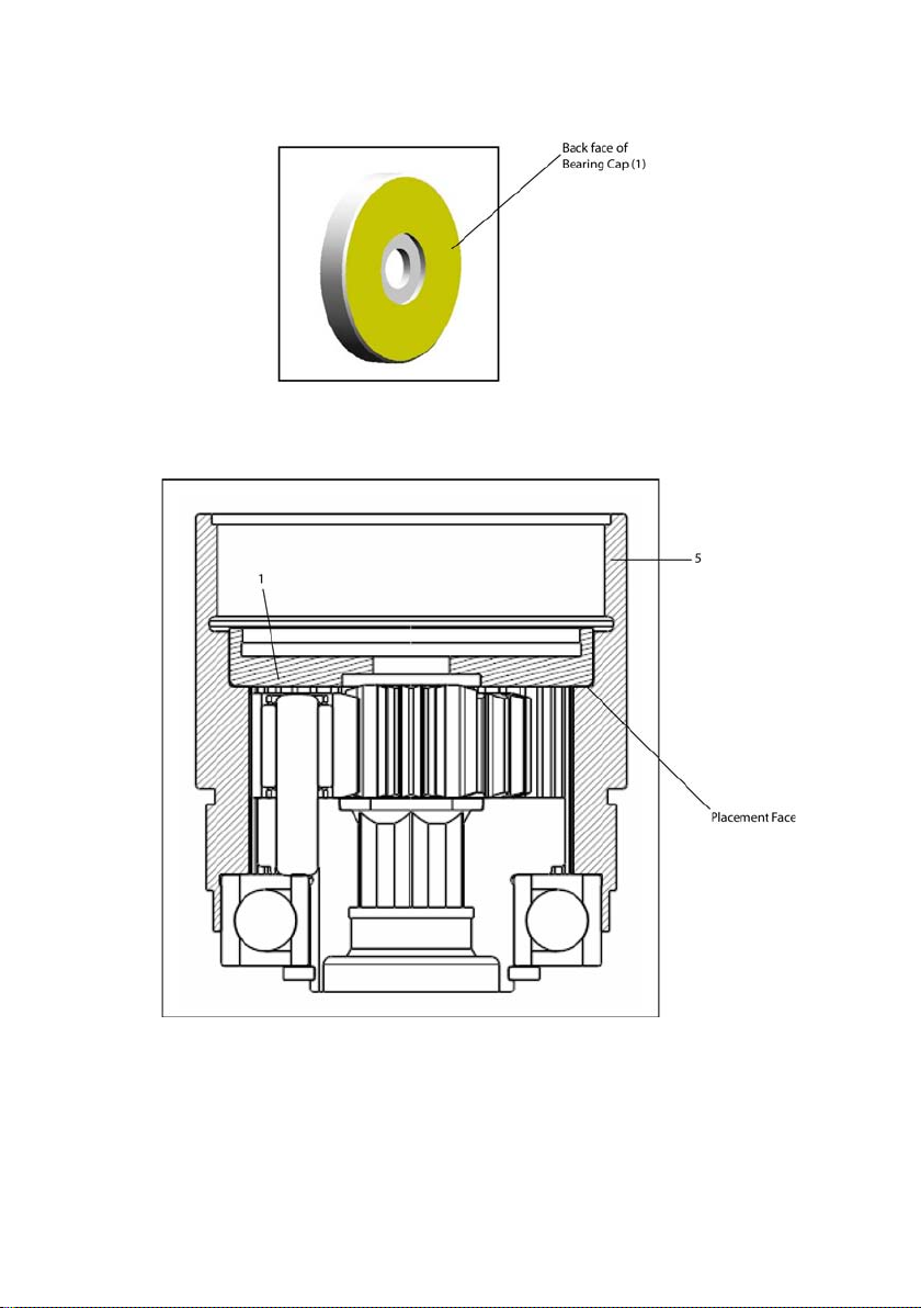
6. Place Front Cap (1) inside the gear case of above assembly. Back face of bearing cap (1) must sits against the placement face of gear case.
See section view below the proper placement.
16601056_ed1 37
Page 38
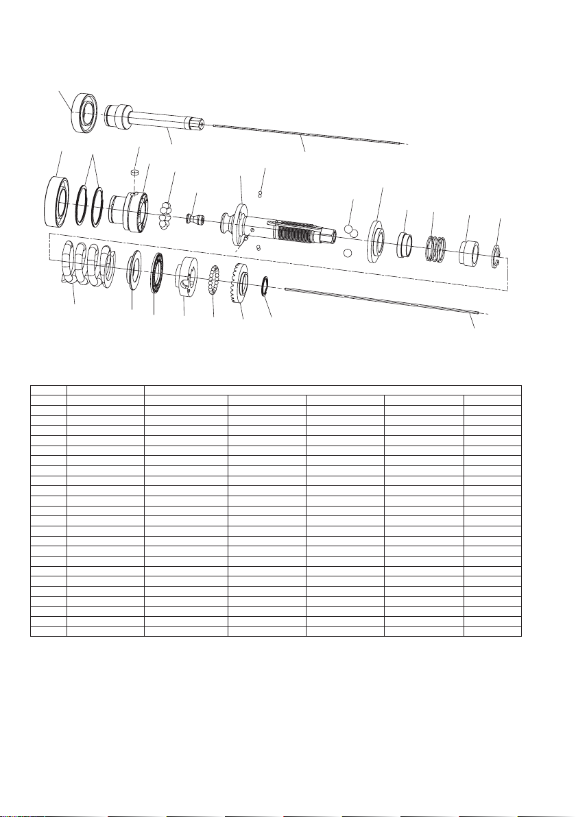
38 16601056_ed1
Clutch and Direct Drive Assembly Exploded View
3
6
5
20
17
8
15
1
7
12
19
14
13
2
10
4
9
6
21
22
16
18
11
7
9
(Dwg. 80227549)
Clutch and Direct Drive Assembly Parts List
Item Part Description Part Number
Clutch Assembly QA8H-A579 QA8L-A579 QA6H-A579 132015 QA6D-A579
1 Clutch Spring QA8-H-583 QA8-L-583 QA6-H-583 QA6-L-583
2 Collar Spring 132066 132066 132066 132066
3 Retaining r ing 182A13-CXRSN50 182A13-CXRSN50 182A13-CXRSN50 182A13-CXRSN50
4 Retaining r ing Y142-20 Y142-20 Y142-20 Y142-20
5 Adjustment Nut 132074 132074 132074 132074
6 Push Rod 132017 132017 132017 132017 132017
7 Bearing 119277 119277 119277 119277 119277
8 Bearing 132059 132059 132059 132059
9 Driver Shaft 132056 132056 132056 132056 QA6-590
10 Spring Guide 132063 132063 132063 132063
11 Circlip 181A13-CXRS106 (2) 181A13-CXRS106 (2) 181A13-CXRS106 (2) 181A13- CXRS106 (2)
12 Plunger 132061 132061 132061 132061
13 Shuto Collar 132062 132062 132062 132062
14 Lower Jaw 132057 132057 132057 132057
15 Spring Guide 132060 132060 132060 132060
16 Plug 126297 126297 126297 126297
17 Nut Lock Washer 132058 132058 132058 132058
18 Upper Driven Jaw 132055 132055 132055 132055
* Ball Kit QA6-1-K581 QA6-1-K581 QA6-1-K581 QA6-1-K581
19 Plunger Ball 2.38 mm (6) (6) (6) (6)
20 Ball 2.78 mm (21) (21) (21) (21)
21 Clutch Ball 6 mm (3) (3) (3) (3)
22 Ball 5 mm (9) (9) (9) (9)
* See Subassembly Exploded View & Parts List for Detail.
Page 39
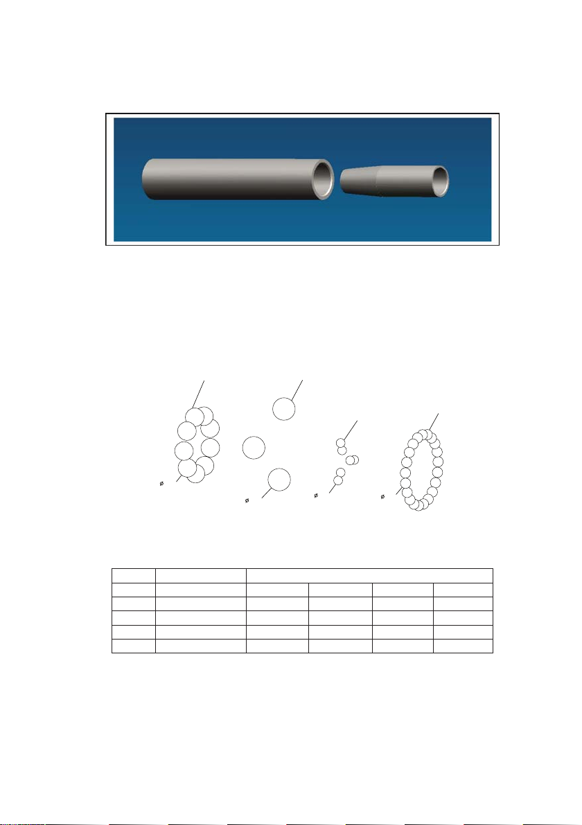
Tooling Required
5.00
22
21
19
20
6.00
2.83
2.78
Specic Tooling
Retaining Ring tool (80187362): This tooling is required for assembly of retaining ring (4). Pliers will not work.
Standard tools and Products
Manual Press
•
tool Pick
•
Ingersoll Rand # 68 Grease
•
Ingersoll Rand # 40036-1 Clutch Grease
•
torx Driver for Clutch Adjustment (125116)
•
Subassemblies
Ball Kit Exploded View
(Dwg. RG_45513850)
Ball Kit Parts List
Item Part Description Part Number
* Ball Kit QA6-1-K581 QA6-1-K581 QA6-1-K581 QA6-1-K581
19 Plunger Ball 2.38 mm
20 Ball 2.78 mm
21 Clutch Ball 6 mm
22 Ball 5 mm
(6) (6) (6) (6)
(21) (21) (21) (21)
(3) (3) (3) (3)
(9) (9) (9) (9)
16601056_ed1 39
Page 40
40 16601056_ed1
Disassembly Instructions for Clutch Module
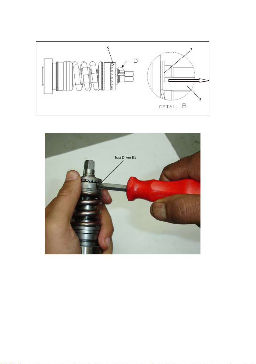
Slip Retaining Ring (3) o of Driver Shaft (9) with Pick to Unlock Adjustment Nut (5). See Detail view below.
1.
2. Insert The Bit of torx Driver (125116) in the teeth of Adjustment Nut and Nut Lock Washer’s (17) Slot. Rotate torx Driver in Clockwise
Direction to loose Adjustment Nut.
Page 41
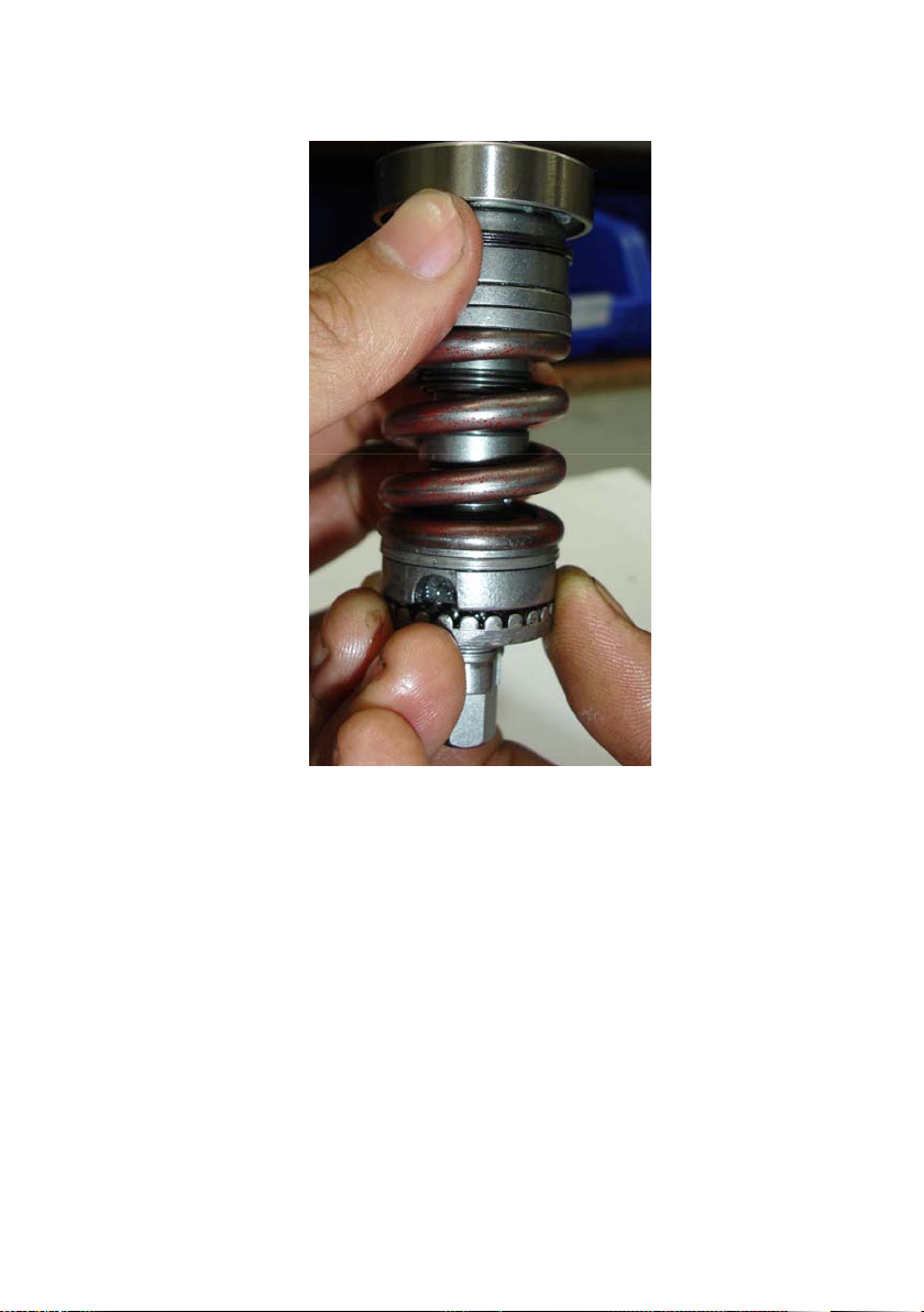
3. Rotate Adjustment Nut in counter clockwise direction to remove.
Note: 1. Hold clutch module in upward direction as shown in view below, otherwise the balls (20) in adjustment nut ball groove will walk out.
16601056_ed1 41
Page 42
42 16601056_ed1
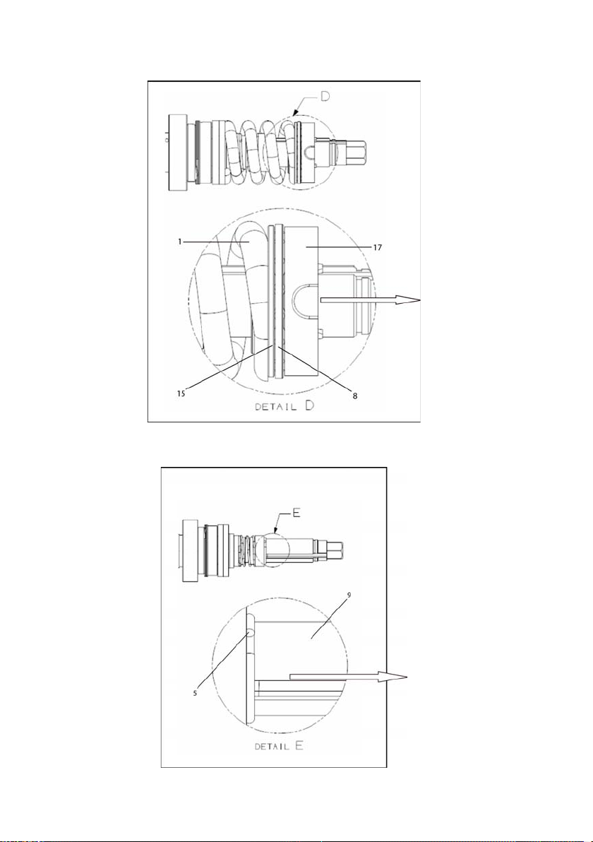
4. Remove Nut Lock Washer (17), Bearing (8), Spring Guide (15) and Clutch Spring (1).
5. Remove Retaining Ring (4) from Driver Shaft’s Retaining Ring Groove by using a pick.
Note: Retaining Ring deforms permanently after removal, destroy it and use a new one.
Page 43
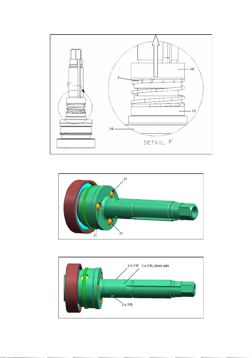
6. Remove Spring Guide (10), Collar Spring (2), Shut-o Collar (13) and Lower Jaw (14).
7. Remove 3 X Clutch Balls 6mm (21) from upper driven jaw’s cam prole.
Note: Check that there are 3 balls and keep them for re-assembly unless heavily worn.
8. Remove 6 X Ball 2.78mm (19) from clutch shaft’s plunger holes.
Note: Check that there are 6 balls and keep them for re-assembly unless heavily worn.
16601056_ed1 43
Page 44
44 16601056_ed1
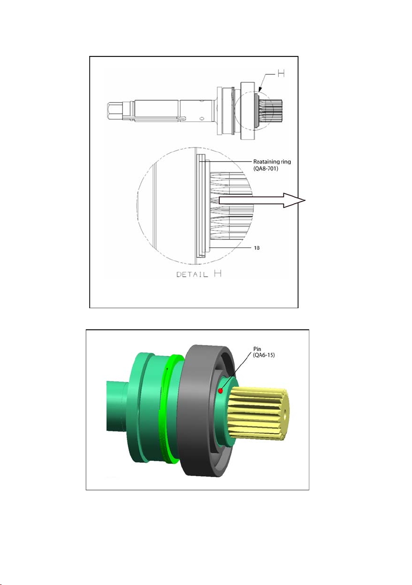
9. Remove Retaining Ring (Qa8-701) from upper driven jaw’s (18) retaining ring groove.
10. Take o Pin (Qa6-15) from upper driven Jaw’s Pin Hole by Inserting A Pin of Diameter Less Than 1.3mm through Pin hole.
Page 45
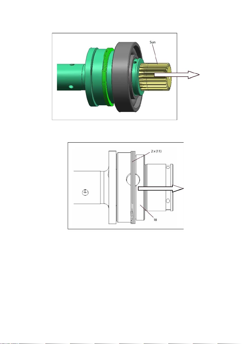
11. Remove Sun from Upper Driven Jaw (18) by Hand.
12. Remove Bearing (7) from Upper Driven Jaw (18) Using Manual Press.
Note: Removal Process Can Damage Bearing. It Is Recommended to use a New Bearing for Assembly.
13. Remove Circlip (11), Qty # 2 from Upper Driven Jaw (18) Using Pick.
16601056_ed1 45
Page 46
46 16601056_ed1
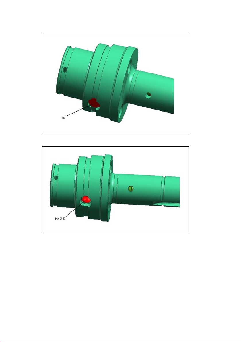
14. Remove Plug from driven jaw by tapping upper driven jaw gently against the work surface.
15. Remove 9 X Balls 5mm (22) by rotating and tapping upper driven jaw gently against the work surface.
Page 47
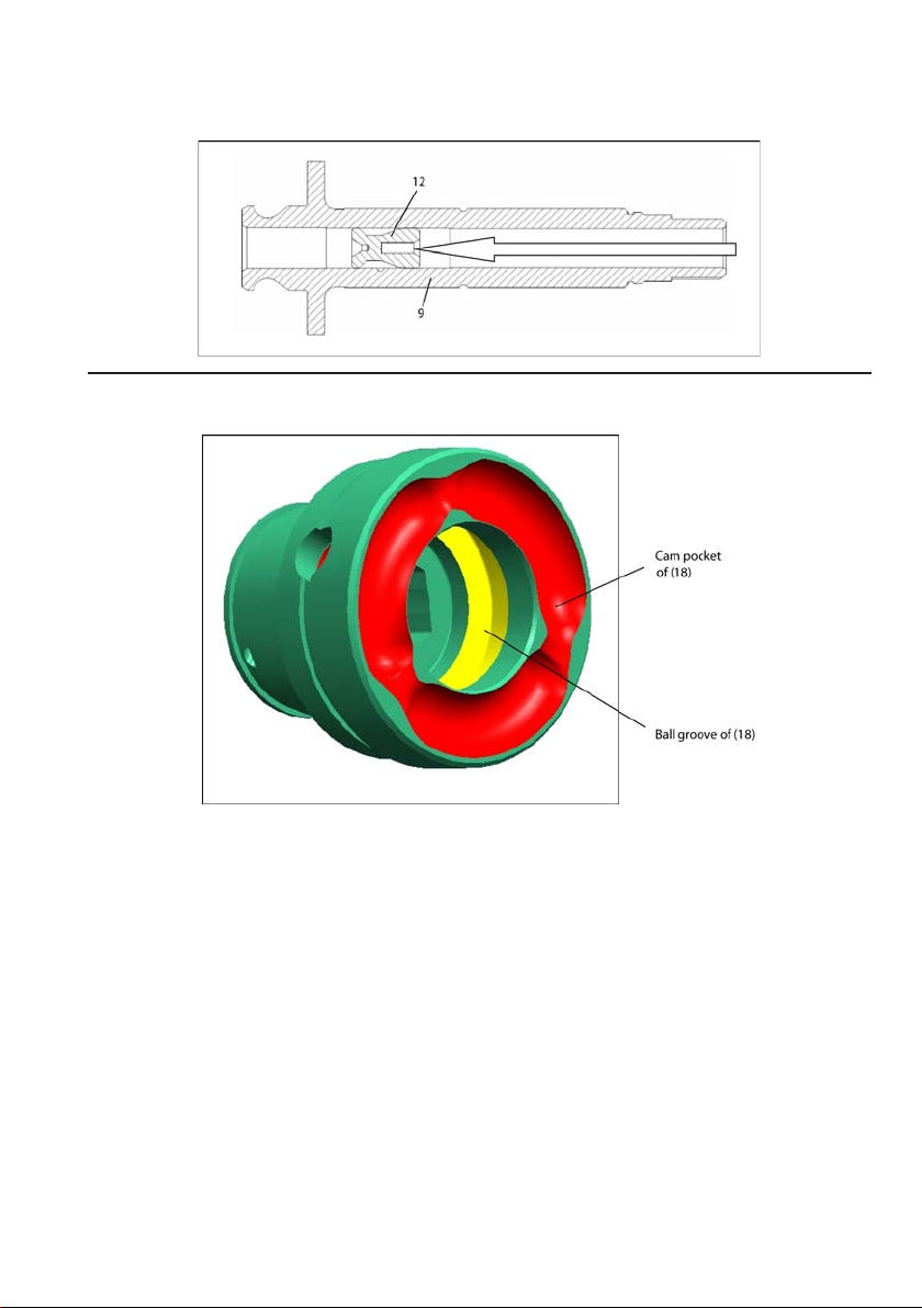
16. once all balls are removed, separate Driver Shaft (9) from Upper Driven Jaw (18).
Note: Check that there are 9 Balls and Keep them for Re-assembly.
Assembly Instructions for Clutch Module
Fill Internal Ball Groove and Cam Pockets of Upper Driven Jaw (18) with Ingersoll Rand # 40036-1 Grease.1.
16601056_ed1 47
Page 48
48 16601056_ed1
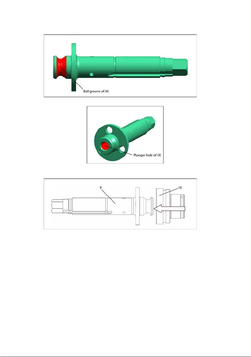
2. Fill Ball Groove and Plunger Hole of Driver Shaft (9) with Ingersoll Rand # 40036-1 Grease.
3. Insert Upper Driven Jaw (18) onto Driver Shaft (9).
Page 49
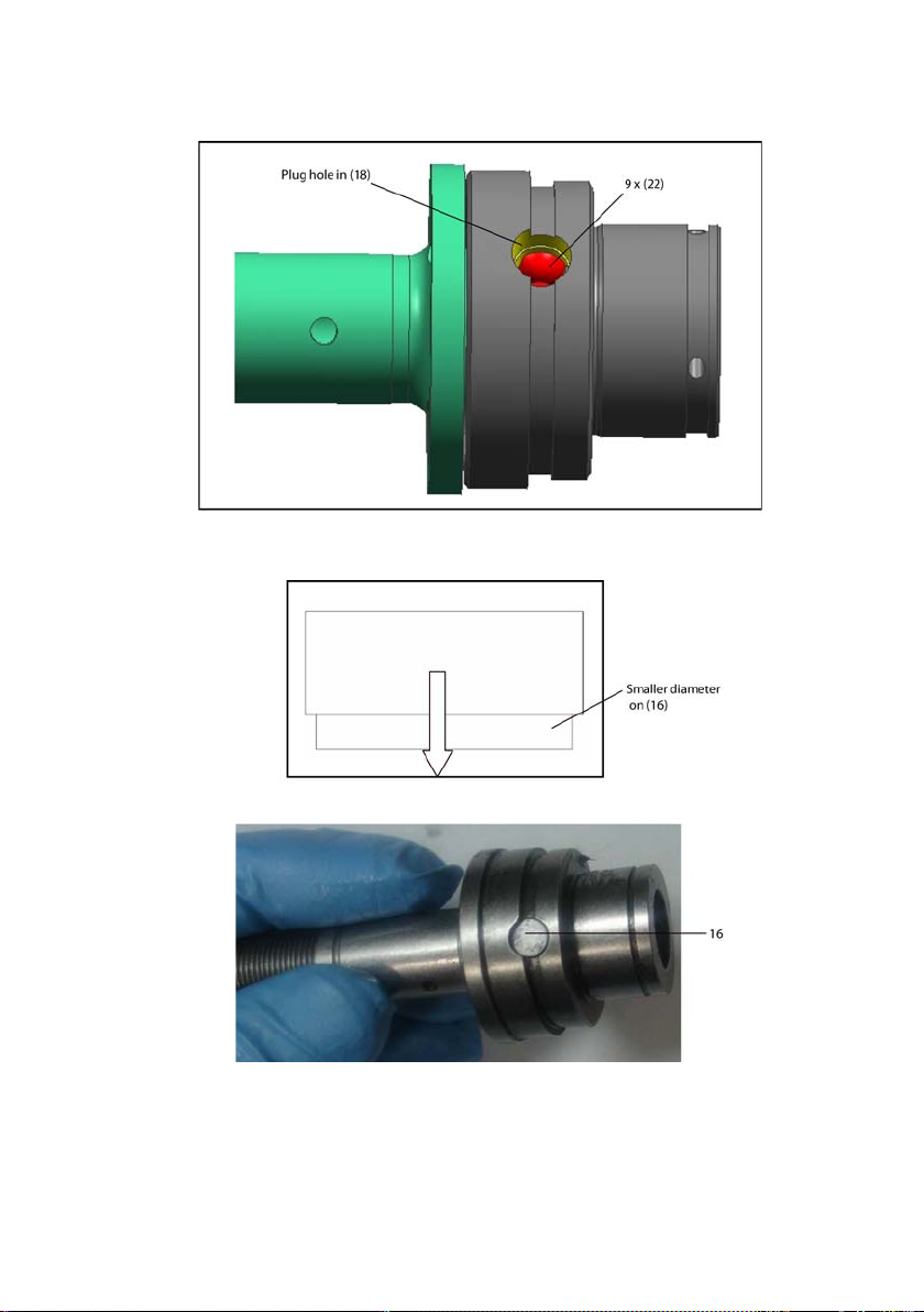
4. Grease 9 X Ball (22) with Ingersoll Rand # 40036-1 Grease. Insert them one by one in the Ball Groove of Driver Shaft (9) and upper driven
jaw (18) through plug hole of upper driven jaw.
5. Place Plug (16) in plug hole of upper driven jaw (18). The smaller diameter of plug must face ball (22) inserted in step (3)
Note: Plug must sit below the retaining ring surface of upper driven jaw.
16601056_ed1 49
Page 50
50 16601056_ed1
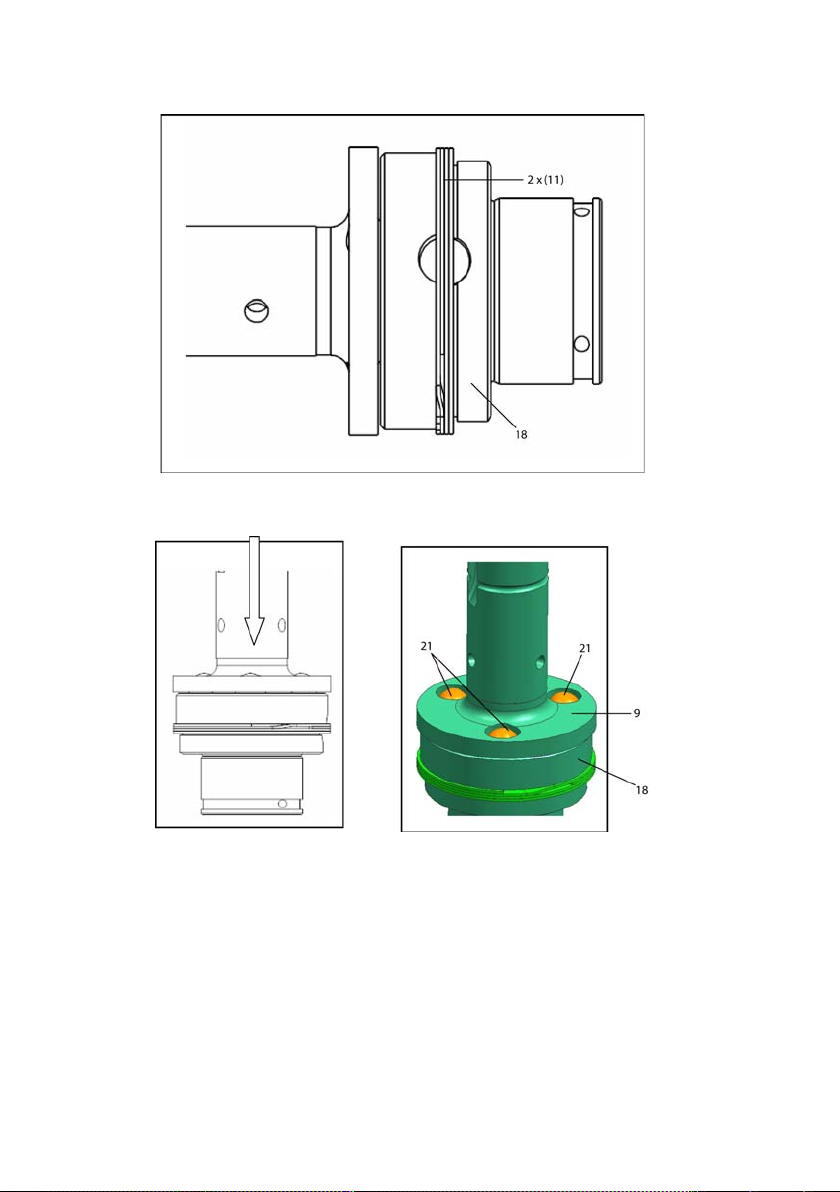
6. Place 2 X Circlip (11) onto upper driven jaw‘s (18) plug retaining ring groove.
7. Grease Ball Pocket of Driver Shaft (9) with Ingersoll Rand 40036-1 Grease.
8. Insert 3 X Clutch Ball 6mm (21) In Upper Driven Jaw‘S (18) Cam Pocket Through Driver Shaft’s (9) Ball Hole.
Page 51
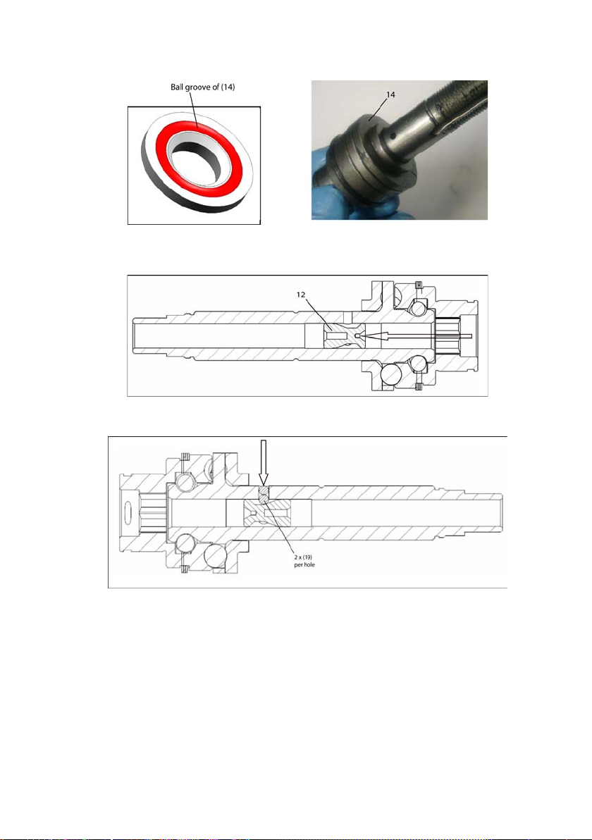
9. Grease ball groove of lower race (14) with Ingersoll Rand # 40036-1 Grease and slide on driver shaft (9).
10. Grease Plunger’s (12) outer surface with Ingersoll Rand # 40036-1 Grease. Insert Plunger Into Driver Shaft’s (9) Hole through upper driven
jaw’s hole. See section view below for the proper placement.
Note: Make sure that the balls placed in step (3) do not walk out.
11. Grease 3 X cross holes of driver shaft with Ingersoll Rand 40036-1 Grease and Insert 2 X Plunger Ball 2.38mm (19) Per Hole. See section view
below for the proper placement.
16601056_ed1 51
Page 52
52 16601056_ed1
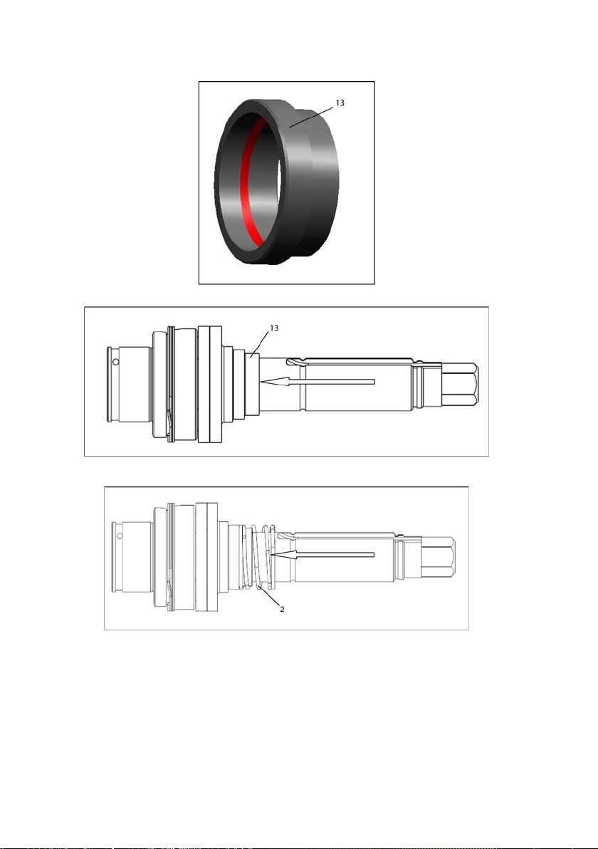
12. Grease I.D of shuto collar (13) with Ingersoll Rand # 40036-1 Grease. Slip shuto collar over drive shaft.
13. Slip Collar Spring (2) over Drive Shaft. Flat face of Collar Spring Must Sit on the Step of Shuto Collar.
Page 53
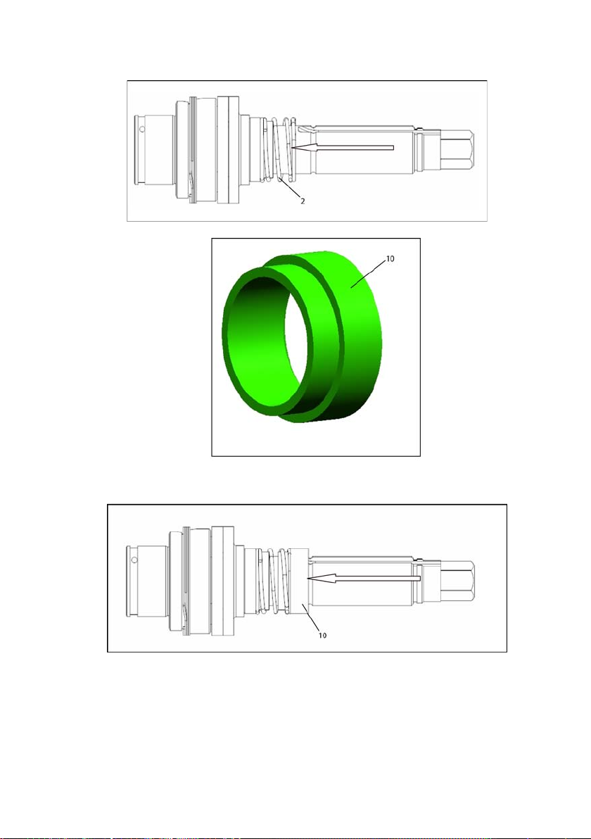
14. Slip Spring Guide (10) over Drive Shaft. The Other Flat Face of Collar Spring must sit on the step of Spring Guide.
16601056_ed1 53
Page 54
54 16601056_ed1
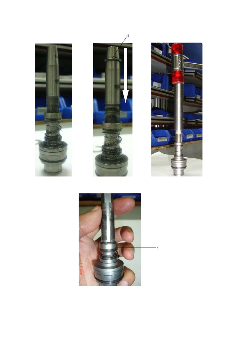
15. Use Retaining Ring tool (80187362) to place Retaining Ring (4) on Driver Shaft (9) Groove.
Note: 1. Check That Retaining Ring (4) is Correctly Positioned onto Driver Shaft’s (9) Groove. 2. Make Sure that the Plunger Positioned in Steps
10 and 11 is in its Position.
Page 55
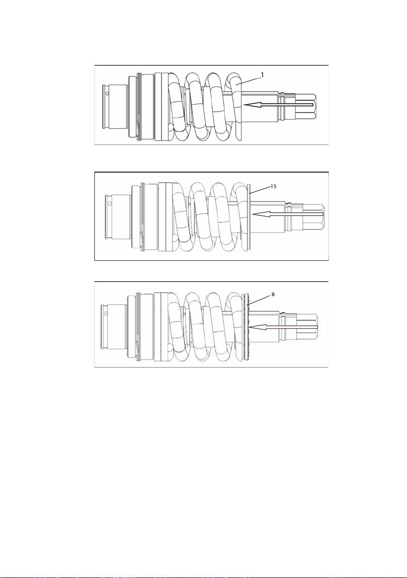
16. Grease collar spring, shuto collar and spring guide with Ingersoll Rand # 40036-1 grease in assembled condition.
17. Coat both the at ends of clutch spring (1) with Ingersoll Rand # 40036-1 Grease. Place clutch spring onto lower jaw (14).
18. Grease both faces of spring guide (15) with Ingersoll Rand # 40036-1 grease and place over clutch spring (1).
19. Grease both faces of Bearing (8) with Ingersoll Rand # 40036-1 grease and place over spring guide (15).
16601056_ed1 55
Page 56
56 16601056_ed1
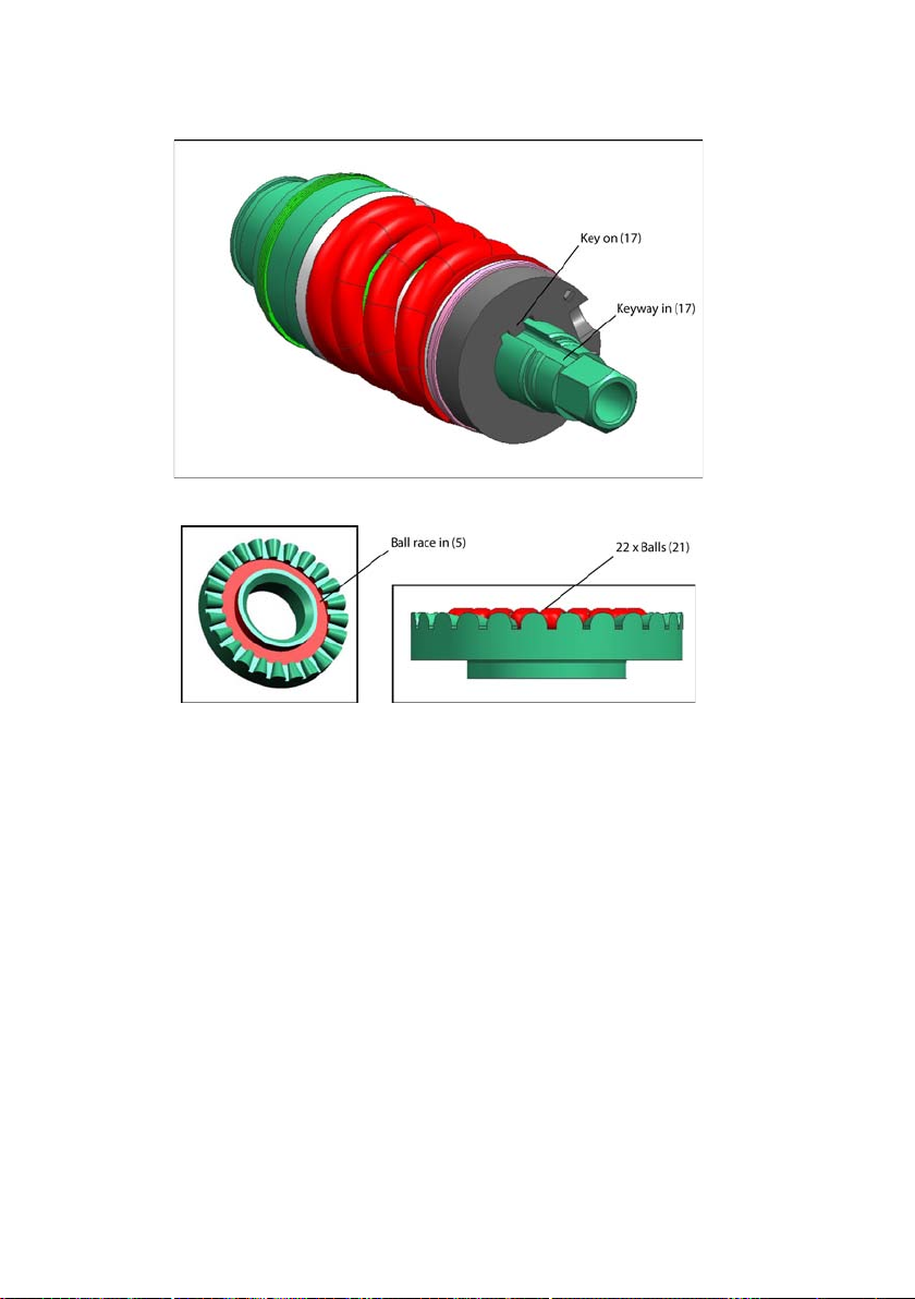
20. Slide Lock Nut Washer (17) onto above Assembly. Align Key on Lock Nut Washer with Keyway In Driver Shaft. See View Below for The Proper
Placement.
21. Grease Ball Race of Adjustment Nut (5) with Ingersoll Rand # 40036-1 Grease and place 22 X Ball 2.78mm (20) in it.
Page 57
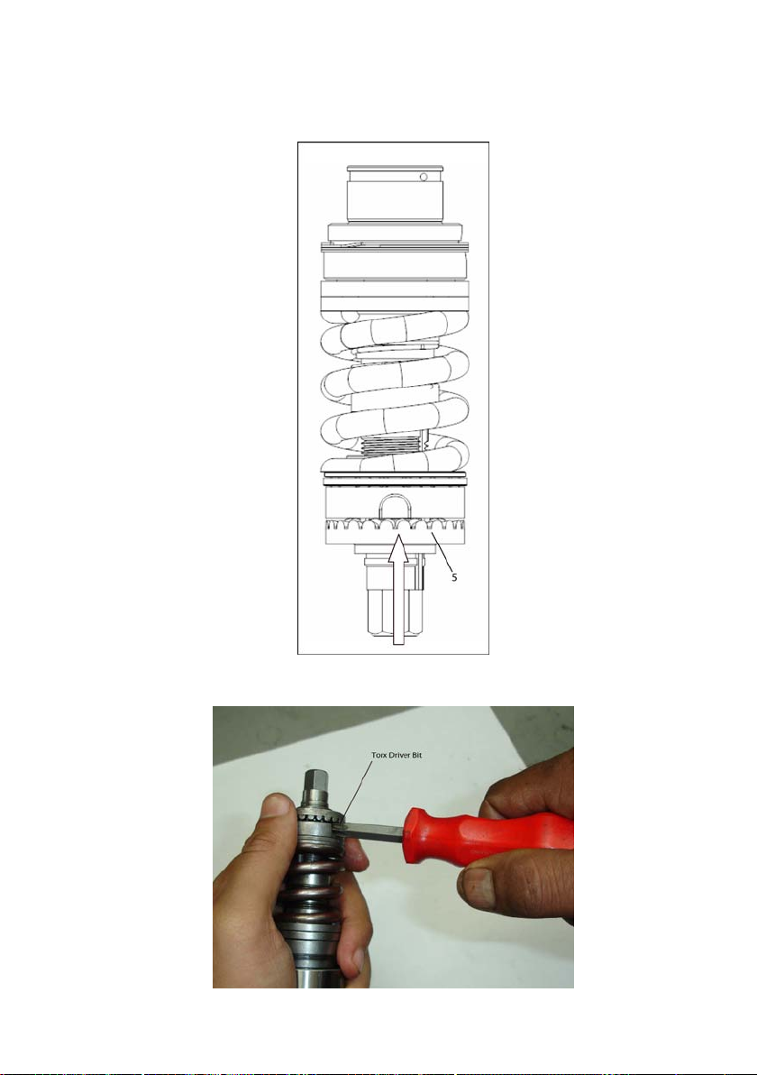
22. Thread Adjustment Nut (5) with balls in it onto Assembly of Step (20) and tightened with hand rst.
Note:
1. Hold assembly in the upward direction as shown in view below, otherwise the balls placed in adjustment nut in Step 21 will walk out.
2. Also Hold Nut Lock Washer (17) in the assembly with hand, otherwise the parts will walk out.
23. Insert the Bit of torx Driver (125116) in the teeth of adjustment nut and nut lock washer’s (17) slot. Rotate torx driver in counter clockwise
direction to tighten adjustment nut.
16601056_ed1 57
Page 58
58 16601056_ed1
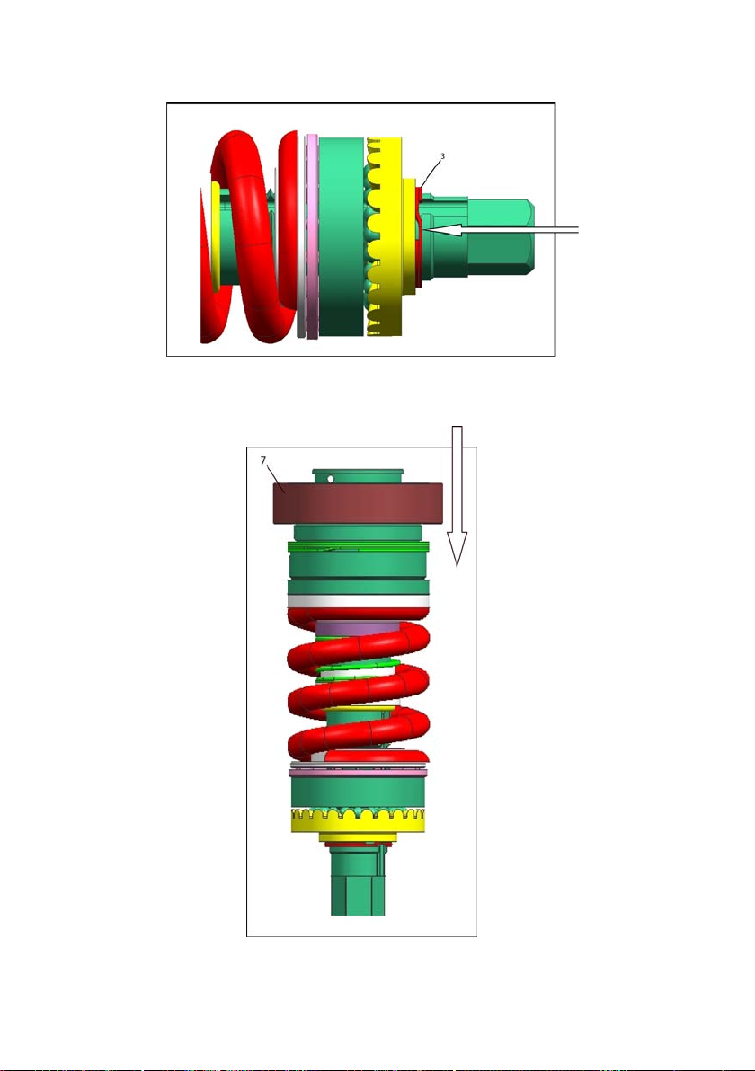
24. Place Retaining Ring (3) on driver shaft’s (9) retaining ring groove.
25. Grease unshielded side of Bearing (7) with Ingersoll Rand # 68 Grease.
26. Mount Bearing (7) onto upper driven jaw (18). Press bearing inner race during pressing.
Note: Unshielded side of bearing must face downward in picture below.
Note: Assemble Push Rod (6), Sun, Pin (Qa6-15) and Retaining Ring (Qa8-701) During Assembly of Complete tool.
Page 59
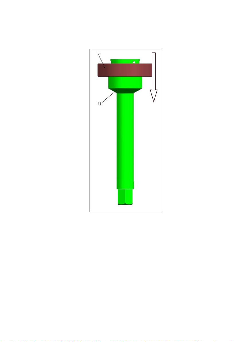
Assembly Instructions for Direct Drive Module
Grease Unshielded Side of Bearing (7) with Ingersoll Rand # 68 Grease.
1.
2. Mount Bearing (7) onto Driver Shaft (18). Press bearing inner race during pressing.
Note: Unshielded side of bearing must face downward in picture below.
Note: Assemble Push Rod (6) during assembly of complete tool.
16601056_ed1 59
Page 60
60 16601056_ed1
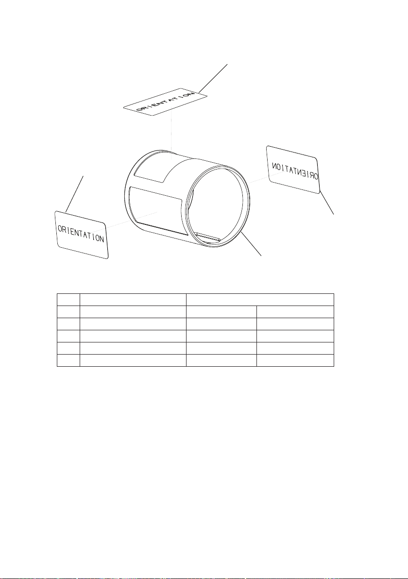
Clutch Cover Assembly Exploded View
4
2
1
3
Clutch Cover Assembly Parts List
Item Part Description Part Number
Clutch Cover Assembly QA6-A415 QA8-A415
1 Clutch Cover
2 Nameplate QA6-301 QA6-301
3 Information Label QA6-299 QA6-299
4 Warning Label WARNING-27-99 WARNING-27-99
Page 61
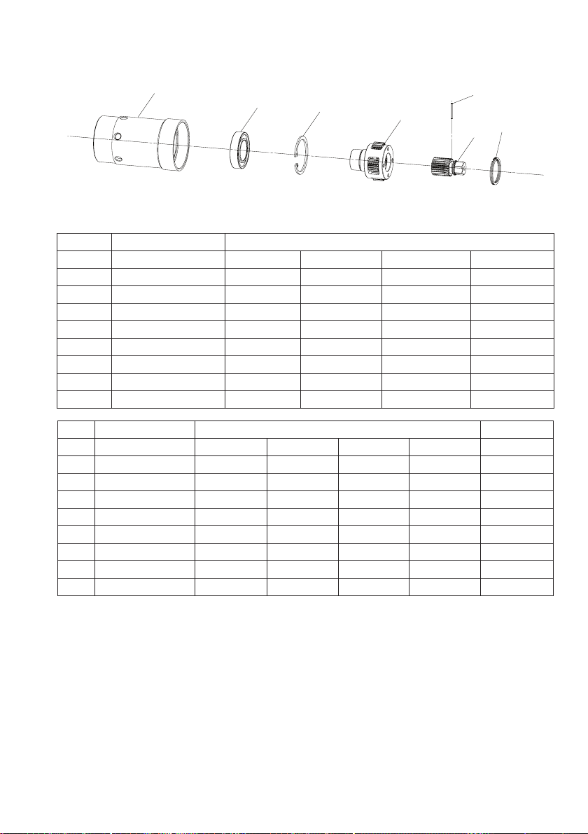
Second Stage Exploded View
2
5
4
3
3
7
6
(Dwg. RG_80221716)
Second Stage Parts List
Item Part Description Part Number
2nd Stage Gear Assembly QA6-M37-3P33 QA6-M37-4P50 QA6-M37-5P08 QA6-M37-4P27
1 Sun QA6-17-3P33 QA6-17-4P50 QA6-17-5P08 QA6-17-4P27
2 Gear Case QA6-1-37 QA6-1-37 QA6-1-37 QA6-1-37
3 Spindle Assembly QA6-A8-3P33 QA6-A8-4P50 QA6-A8-5P08 QA6-A8-4P27
4 Snap R ing 161M13N30 161M13N30 161M13N30 161M13N30
5 B earing R1602-510 R1602-510 R1602-510 R1602-510
6 Pin QA6-15 QA6-15 QA6-15 QA6-15
7 Retaining Ring QA8-701 QA8-701 QA8-701 QA8-701
8* Spacer - - - -
Item Part Description Part Number
2nd Stage Gear Assembly QA8-M37-5P64 QA8-M37-3P68 QA8-M37-3P32-1 QA8-M37- 3P32-2 QA8-M37-4P64
1 Sun QA8-17-5P64 QA8-17-3P68 QA6-17-5P08 QA6-17-5P08 QA6-17-5P08
2 Gear Case QA8-22-37 QA8-22-37 QA8-22-37 QA8-22-37 QA8-22-37
3 Spindle Assembly QA8-A8-5P64 GEA240- A216 QA8-3P32-32-216 QA8-3P32- 31-216 QA8-4P64-32-216
4 Snap Ring
5 Bearing R38P-606
6 Pin QA6-15 QA6-15 QA6-15 QA6-15 QA6-15
7 Retaining Ring QA8-701 QA8-701 QA8-701 QA8-701 QA8-701
8* Spacer - GEA240-80 GEA240-80 GEA240-80 GEA240-80
* Not Illustrated.
Tooling Required
Standard tools and Products
Manual Press
•
Ingersoll Rand # 90 Grease
•
Internal Circlip Pliers
•
Ingersoll Rand # 68 Grease
•
16601056_ed1 61
Page 62
62 16601056_ed1
Assembly Instructions for Second Stage
Assembly of (QA6-M37-3p33), (QA6-M37-4p50), (QA6-M37-5p08), (QA6-M37-4p27)
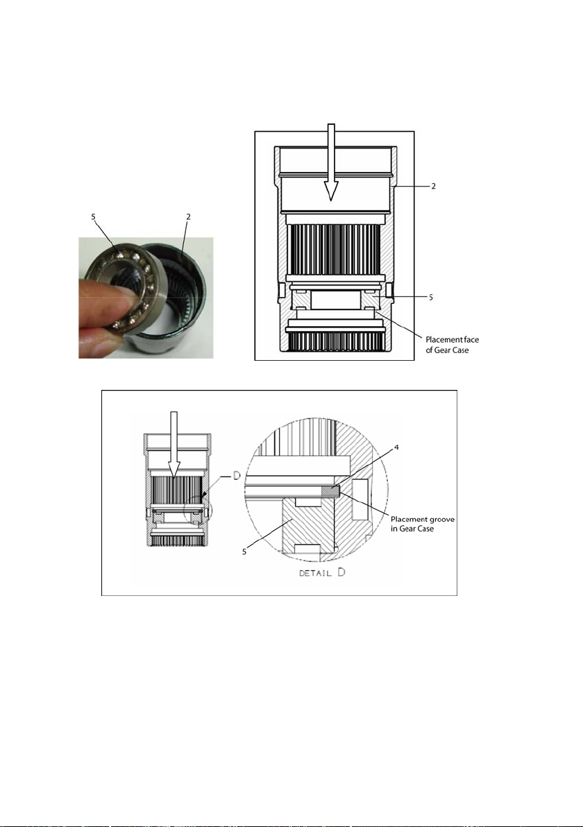
Coat Bearing (5) with Ingersoll Rand# 68 Grease. Place bearing in gear case (2) with hand rst and then press using manual press to butt
1.
against the placement face of gear case. Support bearing outer race during pressing. See section view below for the proper placement.
2. Secure Bearing (5) with Retaining Ring (4) using internal circlip pliers. See section and detail views below for the proper placement.
Page 63
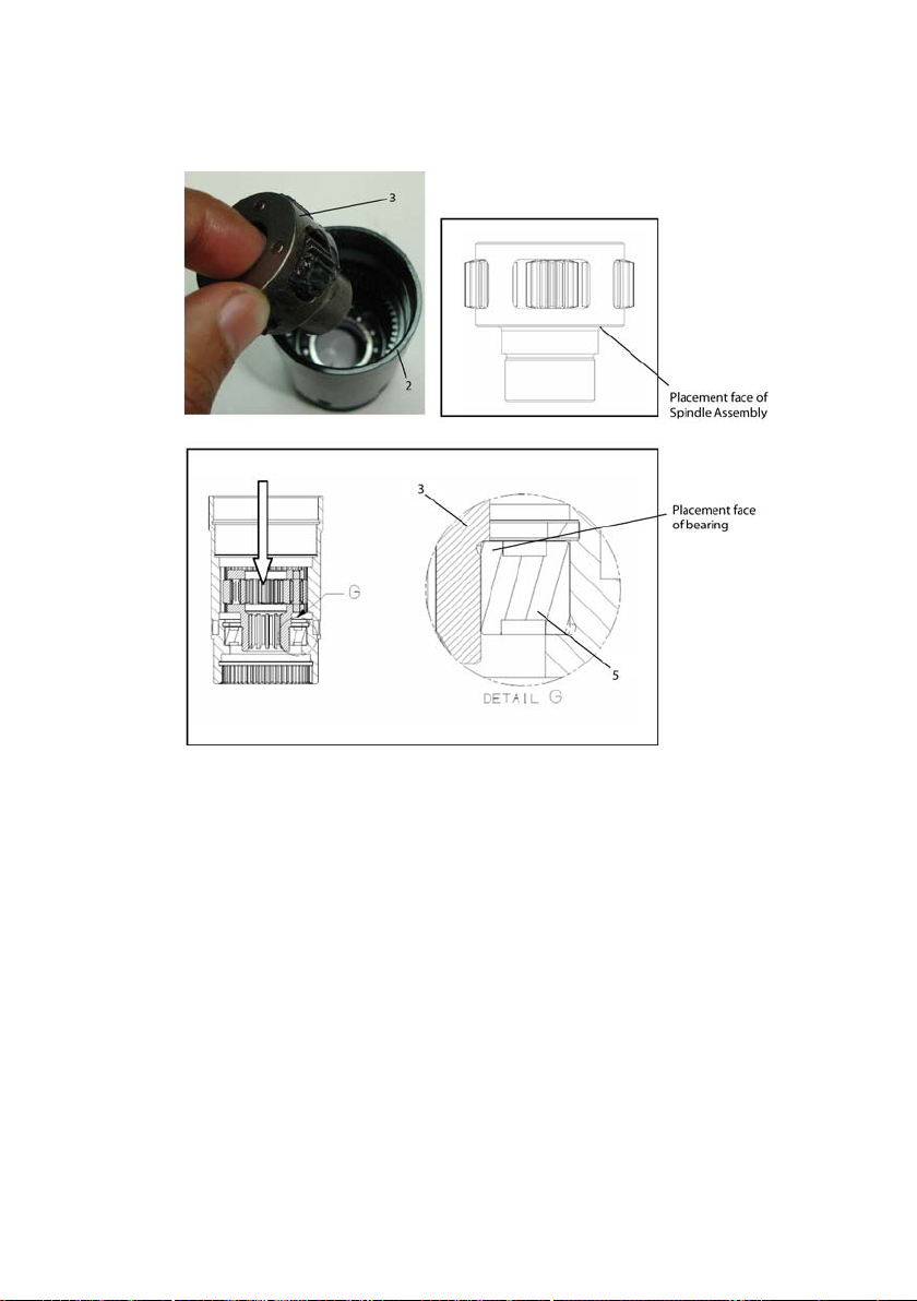
3. Grease Gear Case’s (2) Splines with Ingersoll Rand # 90 Grease. Place spindle assembly (3) onto bearing in gear case with hand rst and
then press using manual press to butt against the placement face of bearing. Support bearing inner race during pressing. See section and
detail views below for the proper placement.
Note: Make sure that gearing matches before pressing spindle assembly onto bearing.
4. Grease Spindle Assembly’s (3) Gears with Ingersoll Rand # 90 Grease.
16601056_ed1 63
Page 64
64 16601056_ed1
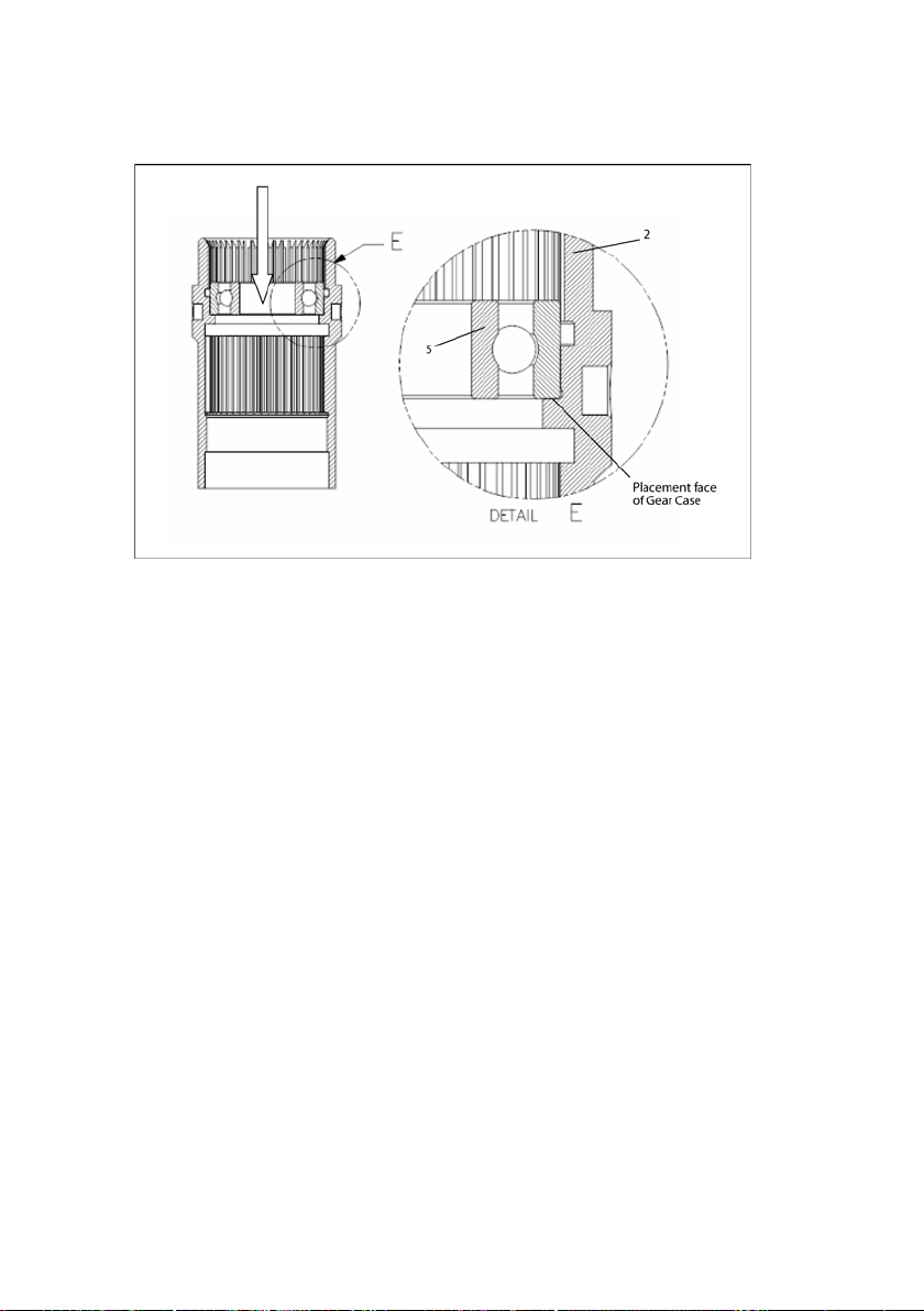
Assembly of (QA8-M37-5p64)
Place Bearing (5) in Gear Case (2) with hand rst and then press using manual press to butt against the placement face of gear case. Support
1.
bearing outer race during pressing. See section and detail views below for the proper placement.
Page 65
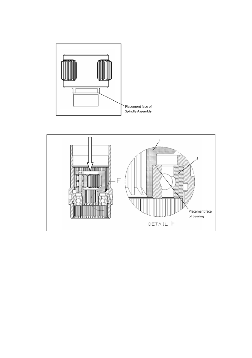
2. Grease Gear Case’s (2) Splines with Ingersoll Rand # 90 Grease. Place Spindle Assembly (3) onto bearing in gear case with hand rst and
then press using manual press to butt against the placement face of bearing. Support bearing inner race during pressing. See section and
detail views below for the placement.
Note: Make sure that gearing matches before pressing spindle assembly onto bearing.
16601056_ed1 65
Page 66
66 16601056_ed1
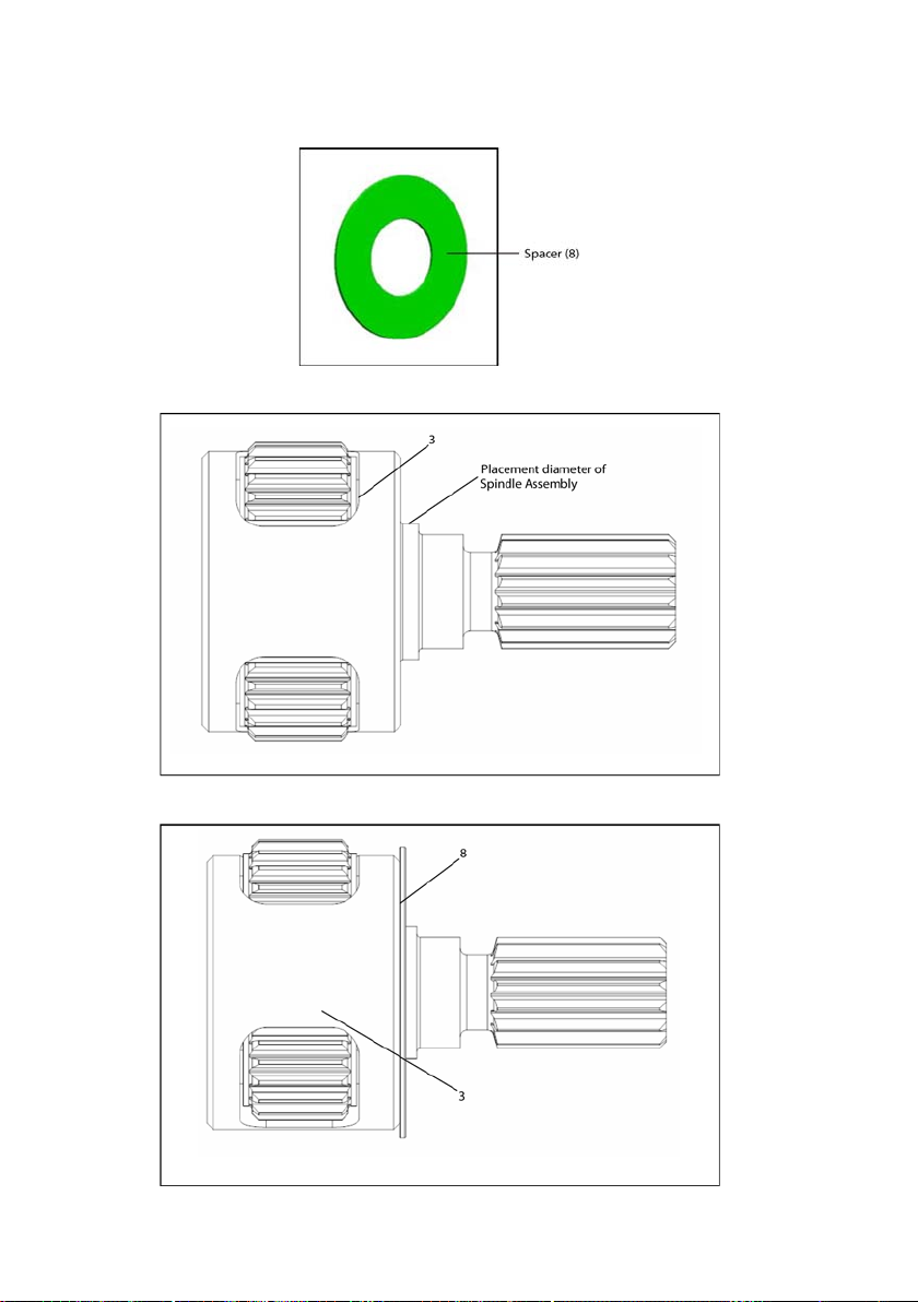
Assembly of (QA8-M37-3p68), (QA8-M37-3p32-1), (QA8-M37-3p32-2), (QA8-M37-4p64)
Grease Spacer’s (8) face with Grease. Grease on spacer’s face is used to hold it on spindle’s face during placing the assembly in gear case.
1.
2. Place Spacer on the placement diameter of spindle assembly (3) and butt against the face of spindle as shown in views below.
Page 67
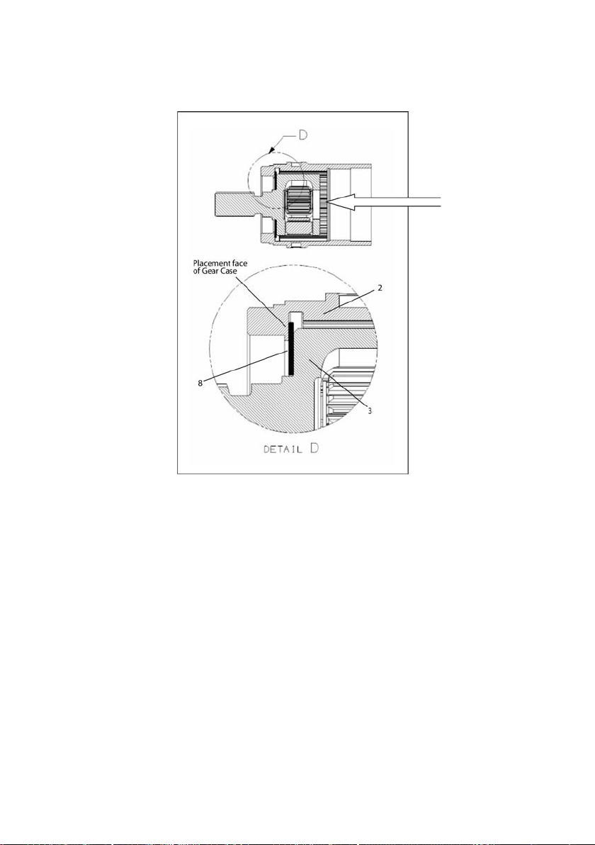
3. Grease Gear Case’s (2) Splines with Ingersoll Rand # 90 Grease. Place The above Assembly ( I.e Spindle Assembly and Spacer) In Gear
Case (2). Spacer (8) Mounted on Spindle Assembly Must Butt Against The Placement Face of Gear Case. See Section View for The Proper
Placement.
Note: Make sure that gearing matches.
4. Grease Spindle Assembly’s (3) gears with Ingersoll Rand # 90 grease.
Note: Assemble Sun (1), Pin (6) & Retaining Ring (7) during assembly of complete tool.
16601056_ed1 67
Page 68
68 16601056_ed1
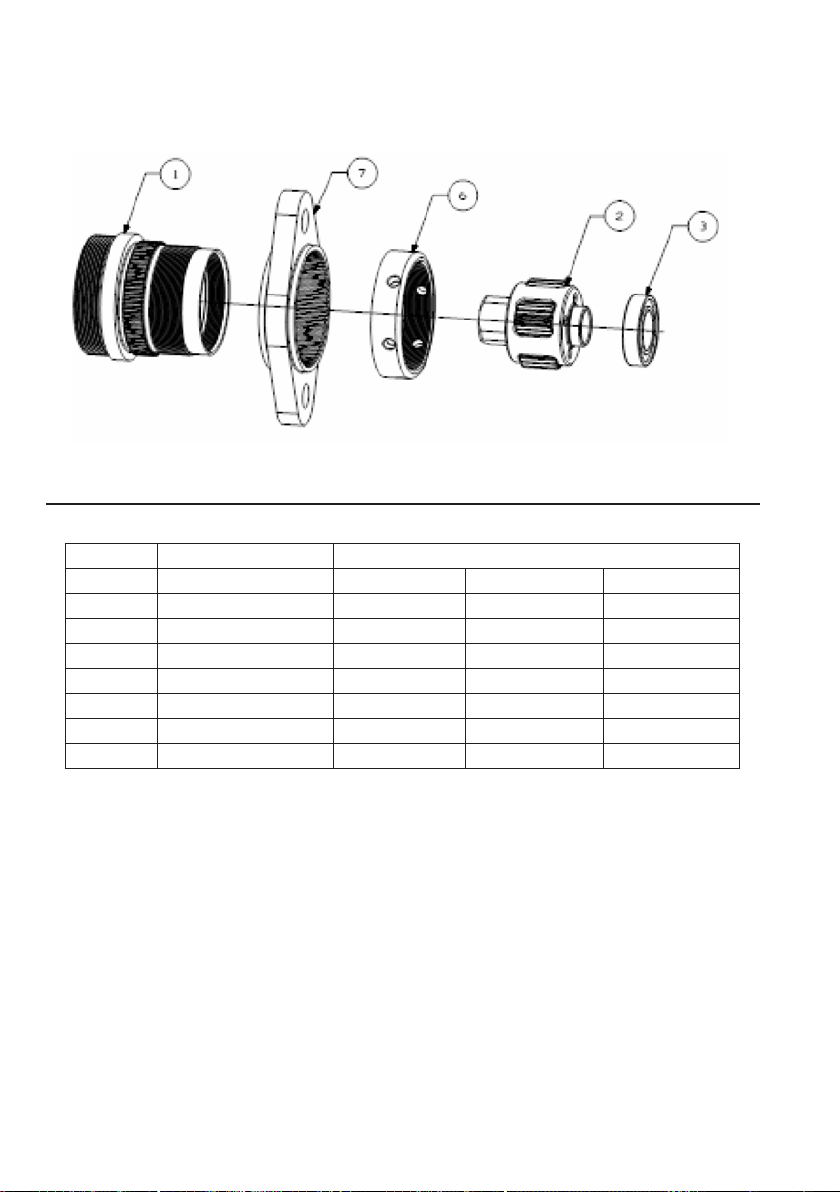
Third Stage Exploded View
(Dwg. RG_80223357)
Third Stage Parts List
Item Part Description Part Number
3rd Stage Gear Assembly QA8-M37-4P29-1 QA8-M37-4P29-2 QA8-M37-4P067
1 Gear Case QA8-31-37 QA8-32-37 QA8-32-37
2 Spindle Assembly QA8-A8-4P29-1 QA8-A8-4P29-2 QA8-A8-4P067
3 Bearing R1602-510 R1602-510 R1602-510
4* Spacer QA8-208 - -
5* Spacer QA8-442 - -
6 Coupling Nut - QA8-47 QA8-47
7 Flange - QA8-48 QA8-48
* Not Illustrated.
Tooling Required
Standard tools and Products
Manual Press
•
Ingersoll Rand # 90 Grease
•
Ingersoll Rand # 68 Grease
•
Torque Wrench
•
Spanner Wrench
•
Page 69
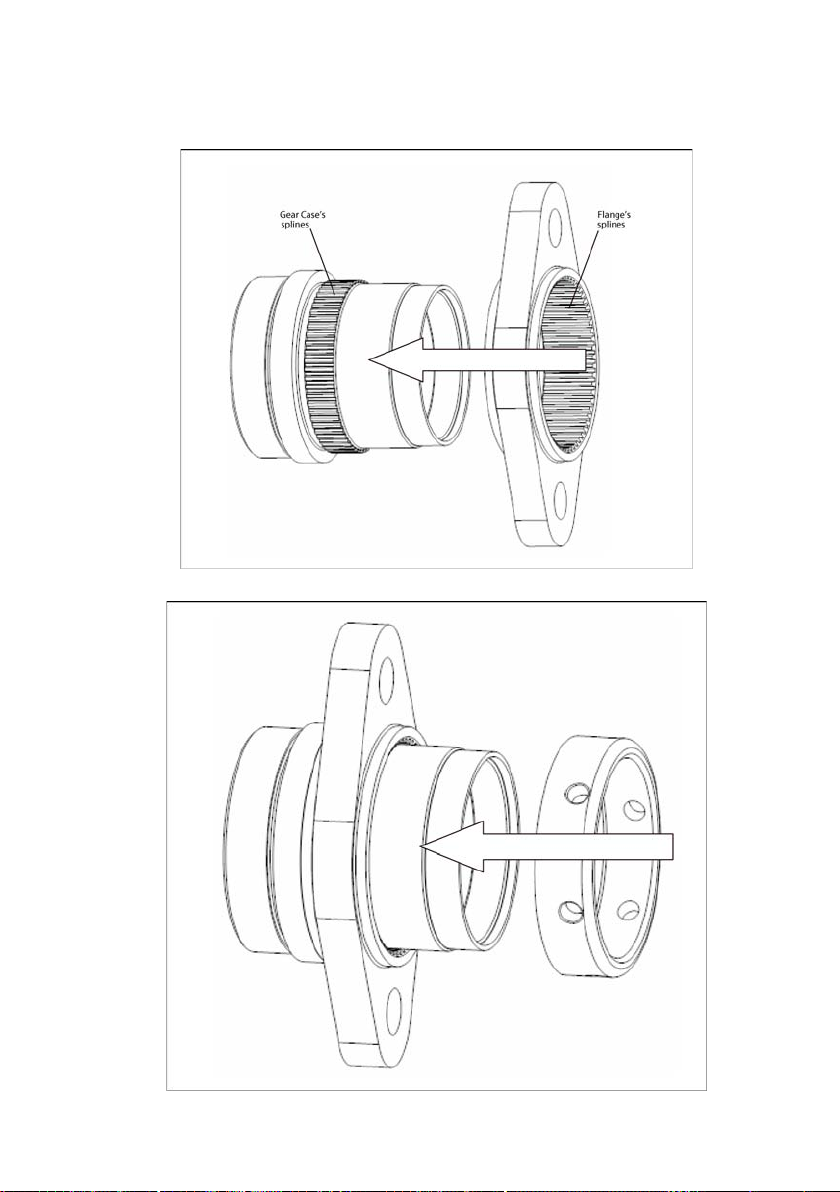
Assembly Instructions for Third Stage
Mount Flange (7) on Gear Case (1). Match gear case’s splines with ange’s splines.
1.
Note: See tool Assembly section for proper mounting.
2. Tighten Coupling Nut (6) Counterclockwise onto Gear Case (1) to 90 Nm (66 Ft-lb) by using a torque wrench.
16601056_ed1 69
Page 70
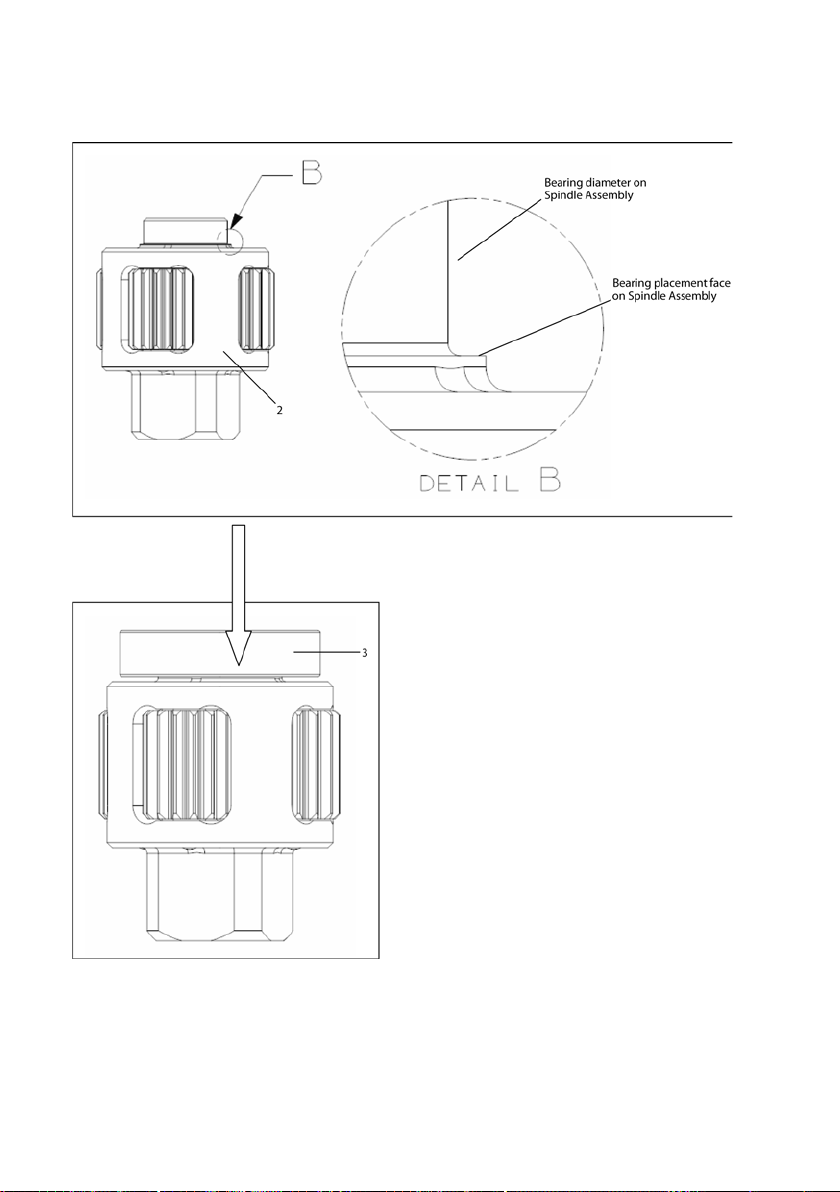
70 16601056_ed1
3. Grease Bearing (3) with Ingersoll Rand # 68 Grease.
4. Press Bearing onto bearing diameter of spindle assembly (2) to butt against the bearing placement face. Support bearing inner race during
pressing. See views below for the proper placement.
Page 71
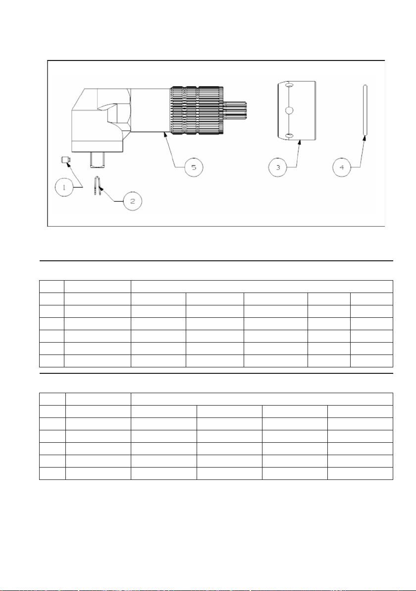
Angle Head Asembly Exploded View
Dwg. RG_80223563)
Note: All Angle Head Assembly and oat spindle assembly are sold as complete assembly to ensure maximum life of tool. Parts details,
exploded views and assembly instructions are provided for loose parts only.
Angle Head Assembly Parts List
Item Part Description Part Number
Angle Head Assembly QA6-R35S06- A550 QA6-R35S08- A550 QA6-R43S08- A550 GAA6S8 AA16S12
1 Pin 131617 132048 804-716 804-716
2 Spring 124491 124492 5UHD-718 5UHD-718
3 Coupling Nut 15E2-27 15E2-27 15E2-27 DAA4-27
4 Coupling Nut Retainer GEA2-29 GEA2-29 GEA2-29 DAA4-29
5 Angle Head Subassembly
Float Spindle Assembly Parts List
Item Part Description Part Number
Spindle Assembly QA64S6 QA64S8 GE4S8 160E4S8
1 Retainer 5020-716 804-716 804-716 804-716
2 Spring 401-718 5UHD-718 5UHD-718 5UHD-718
3 Coupling Nut 15E2-27 15E2-27 DAA4-27 GEA240-27
4 Coupling Nut Retainer GEA2-29 GEA2-29 DAA4-29 160E4-29
5 Spindle subassembly
16601056_ed1 71
Page 72
72 16601056_ed1
Tooling Required
Standard tools and Products
Vice
•
Heavy Duty Retaining Ring Pliers
•
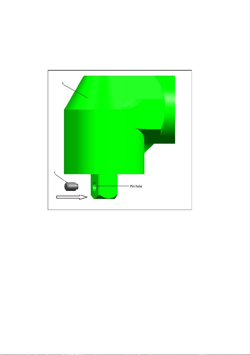
Assembly Instructions for Pin/retainer and Spring
Insert Pin/Retainer (1) in the pin hole of output shaft of angle head subassembly (5).
1.
Page 73
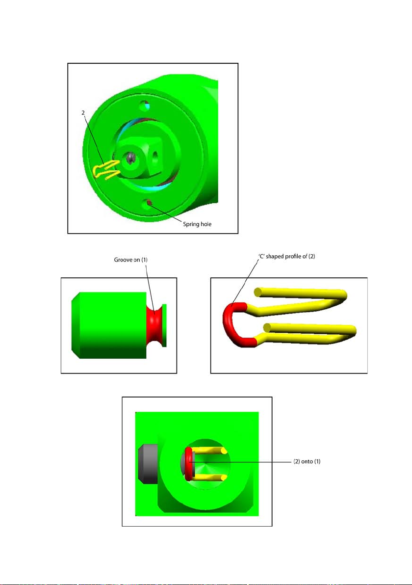
2. Insert Spring (2) in the spring hole of output shaft of above assembly. Press with hand to slip it over the groove of pin (1). ‘C’ shaped prole
of spring (2) must sit onto the groove of pin (1). See views below for the proper placement.
16601056_ed1 73
Page 74
74 16601056_ed1
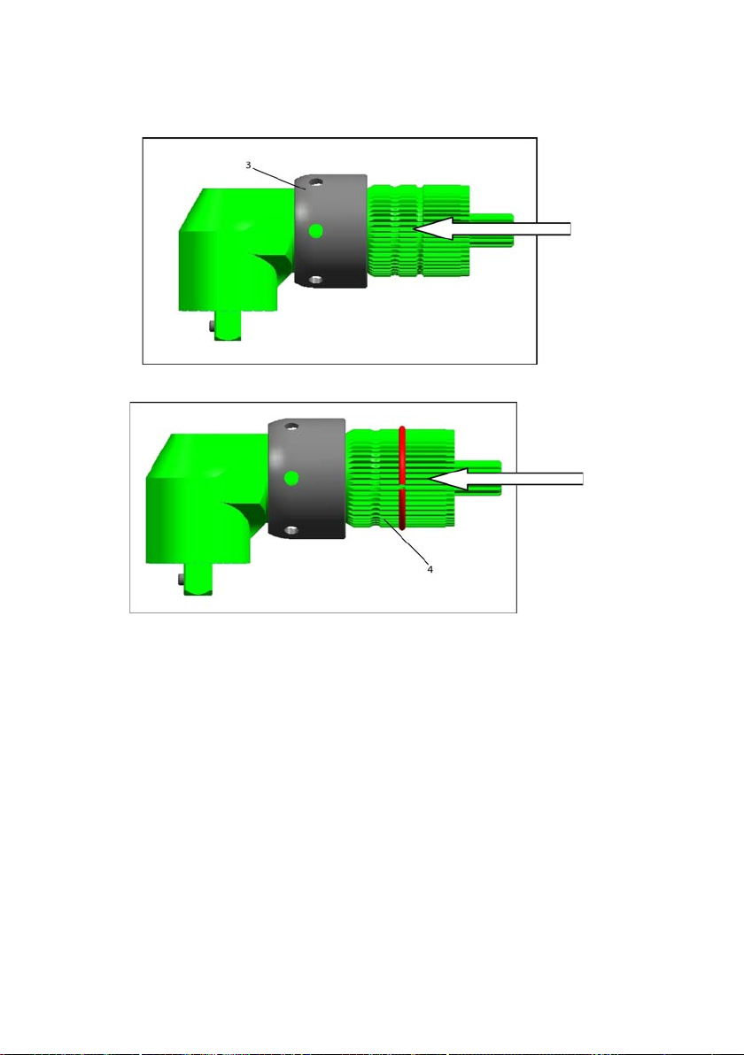
Assembly Instructions for Coupling Nut and Coupling Nut Retainer
1. Slide Coupling Nut (3) over Angle Head Subassembly.
Note: Coupling Nut must be orientated as shown in view below.
2. Place Coupling Nut Retainer (4) on the groove of angle housing of above assembly by using heavy duty retaining ring pliers.
Page 75
Assembly Instructions for Complete tool
2
1
3
4
Tooling Required
Standard tools and Products
Spanner Wrench
•
Vice
•
Torque Wrench
•
Ingersoll Rand # 68 Grease
•
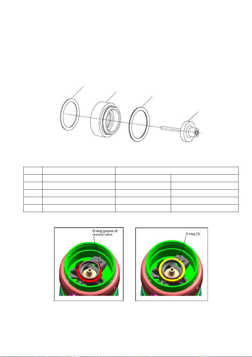
Valve Assembly Exploded View
(Dwg. RG_45504628)
Valve Assembly Parts List
Item Part Description Part Number
Valve assembly QA6-A159 QA8-A159
1 Valve Seat QA6-A159 QA8-A159
2 O-Ring 15.6 mm
3 O-Ring 17.17 mm
4 Shut o Valve 131128 131128
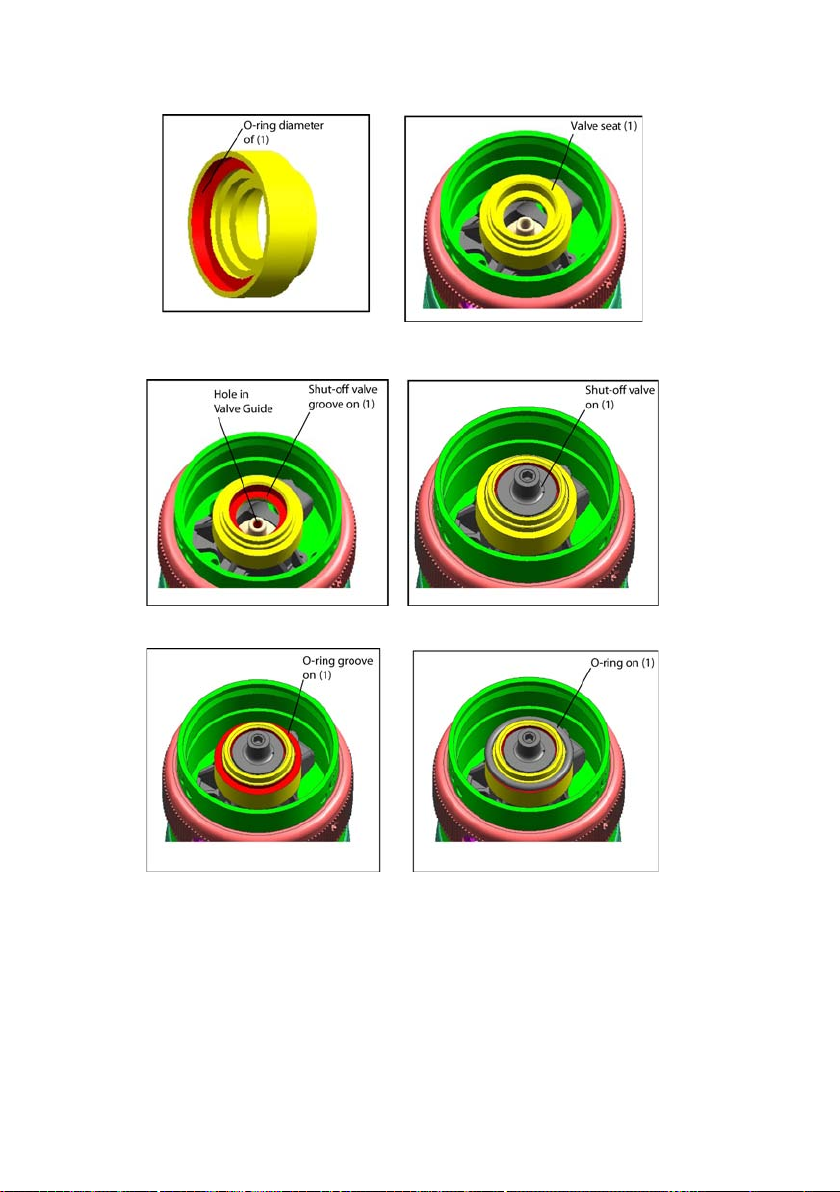
1. Grease O-ring (2) with Ingersoll Rand # 68 Grease. Mount it over the O-ring groove of reverse valve assembled in motor housing module.
16601056_ed1 75
Page 76
76 16601056_ed1
2. Mount Valve Seat (1) over The O-ring of above Assembly. Make sure that the O-ring (2) sits on the o-ring diameter of valve seat.
3. Place Shut-o Valve (4) on the shut-o valve groove of valve seat (1) of above assembly. Make sure that stem of shut-o valve passes
through the hole in valve guide in motor housing.
4. Grease O-ring (3) with Ingersoll Rand # 68 Grease. Mount It over The O-ring Groove (External) of Valve Seat (1) of above Assembly.
Page 77
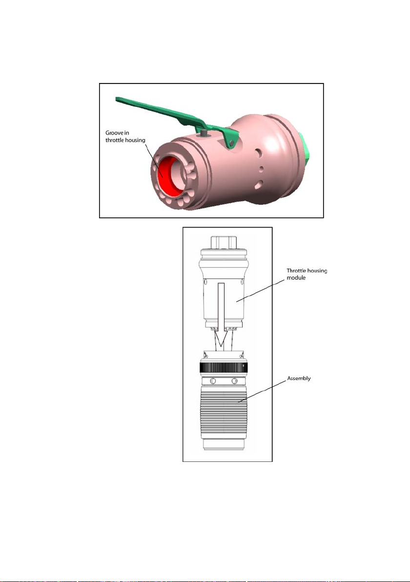
Assembly Instructions for Throttle Housing Module and Assembly (A)
1. Mount Throttle Housing Module onto above Assembly (A). The o-ring mounted in the motor housing module must sit in the groove of
throttle housing. Thread the assembly clockwise by hand rst and then tighten to 40 nm (30 ft-lb) by using spanner wrench and a torque
wrench.
16601056_ed1 77
Page 78
78 16601056_ed1
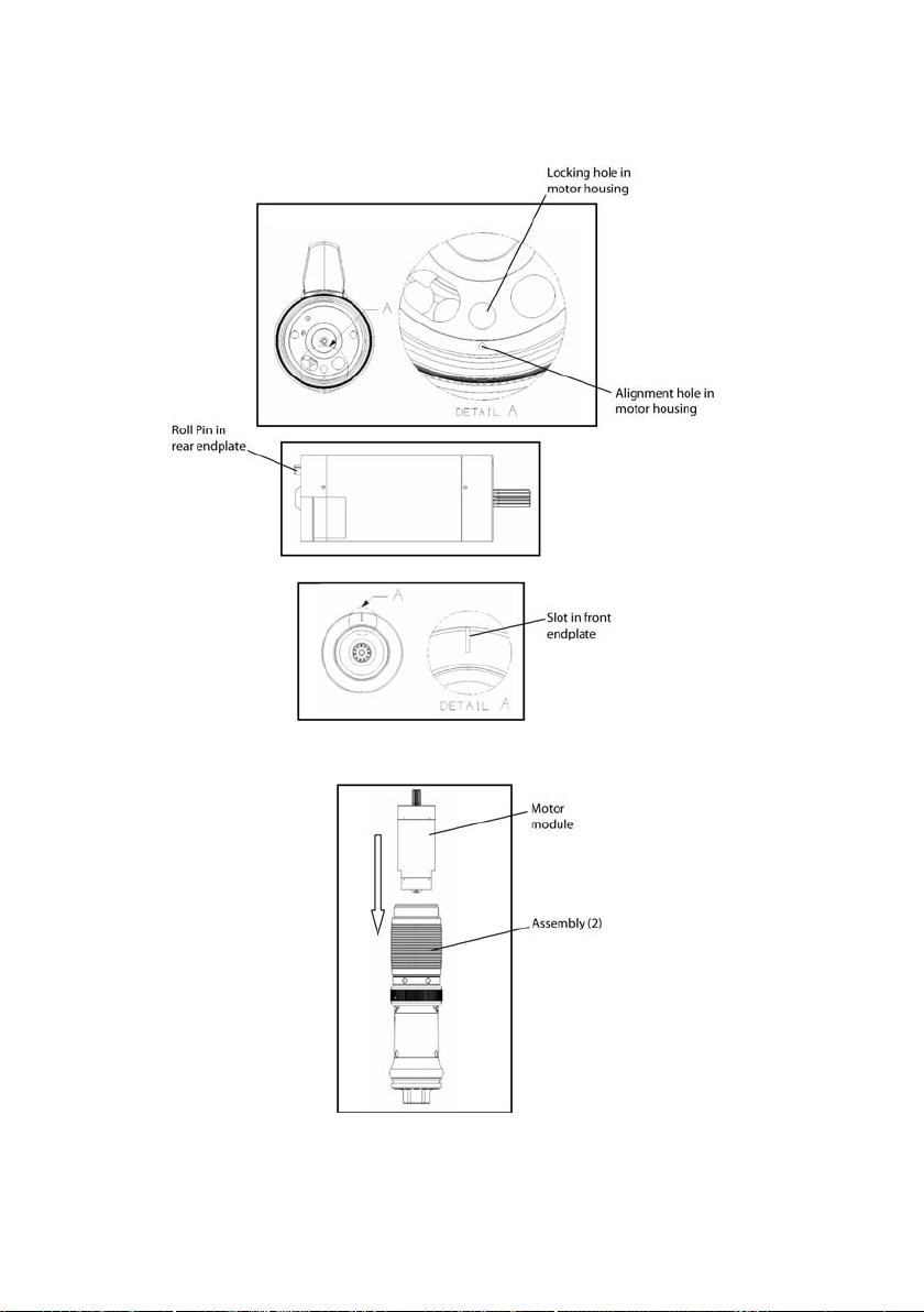
Assembly Instructions for Motor Module and Assembly (B)
1. Place Motor module inside the motor housing of above assembly (b). Align slot in front endplate with alignment hole in motor housing to
make sure that the roll pin in rear endplate goes into locking hole in motor housing.
Note: Make sure that the roll pin in the rear endplate of motor module goes into the locking hole in motor housing of assembly (b).
Page 79
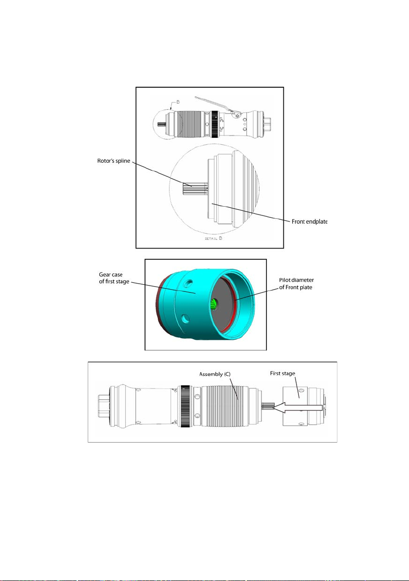
Assembly Instructions for First Stage and Assembly (C)
Mount First Stage onto above Assembly (C). Align rotor’s splines with rst stage’s planet gears. Also the pilot diameter of front cap in rst
1.
stage must pilot onto front endplate in motor module. Thread gear case with motor housing of assembly (c) clockwise by hand rst and then
tighten to 40 nm (30 ft-lb) clockwise by using spanner wrench and a torque wrench.
Note: Do not over or under torque, motor may not function properly.
16601056_ed1 79
Page 80
80 16601056_ed1
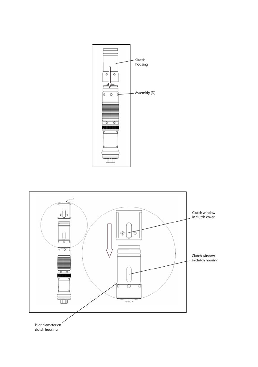
Assembly Instructions for Clutch Housing and Assembly (D)
Thread Clutch Housing with the gear case of above assembly (D) clockwise by hand rst and then tighten to 70 Nm (52 Ft-Lb) clockwise by
1.
using spanner wrenches and a torque wrench.
Assembly Instructions for Clutch Cover and Assembly (E)
Slide Clutch Cover Assembly onto Clutch Housing of above assembly (E). it must sit on pilot diameter of clutch housing and adjust in a way
1.
so that the clutch window in clutch cover opens clearing onto the clutch window in clutch housing of above assembly (E).
Page 81
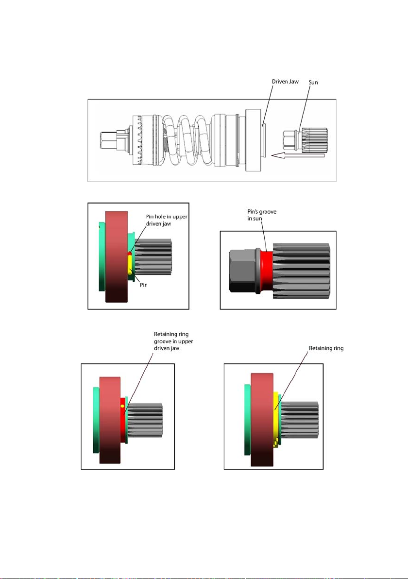
Assembly Instructions for Sun, Retaining Ring, Pin and Clutch Module
Note: Refer to Second stage module parts list for the selection of Sun for a particular module.
1. Place Hex side of Sun in the Upper Driver jaw of Clutch module.
2. Insert Pin (QA6-15) into Upper Driven Jaw’s pin hole to hold Sun in upper driven jaw. Pin must sit over the pin’s groove in Sun.
3. Place Retaining Ring (QA8-701) onto retaining ring groove of Upper driven jaw to Pin (QA6-15) in place.
16601056_ed1 81
Page 82
82 16601056_ed1
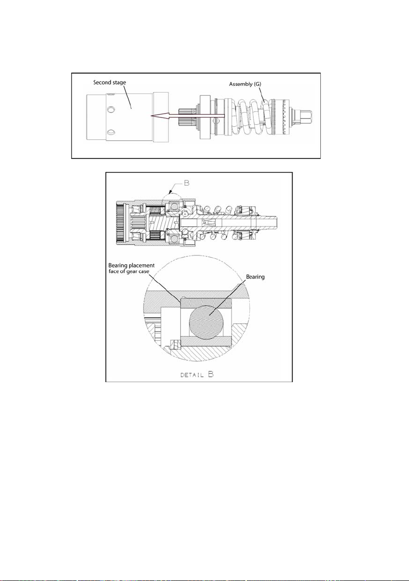
Assembly Instructions for Second Stage and Assembly (G)
Place Assembly (G) in Second stage. Align Sun’s gears with the second stage’s planet gears. Also the bearing of clutch module must sit
1.
against the bearing placement face of the gear case of second stage.
Page 83
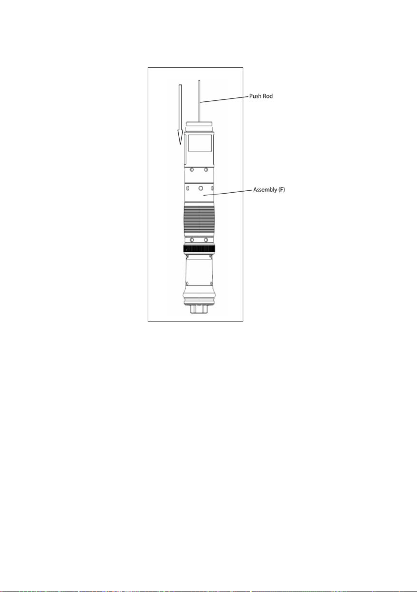
Assembly Instructions for Push Rod, Assembly (F) and (H)
Slide Push Rod (132017) through First Stage’s gearing and Rotor’s hole of Assembly (F).1.
16601056_ed1 83
Page 84
84 16601056_ed1
Assembly Instructions for Assembly (H) and (I)
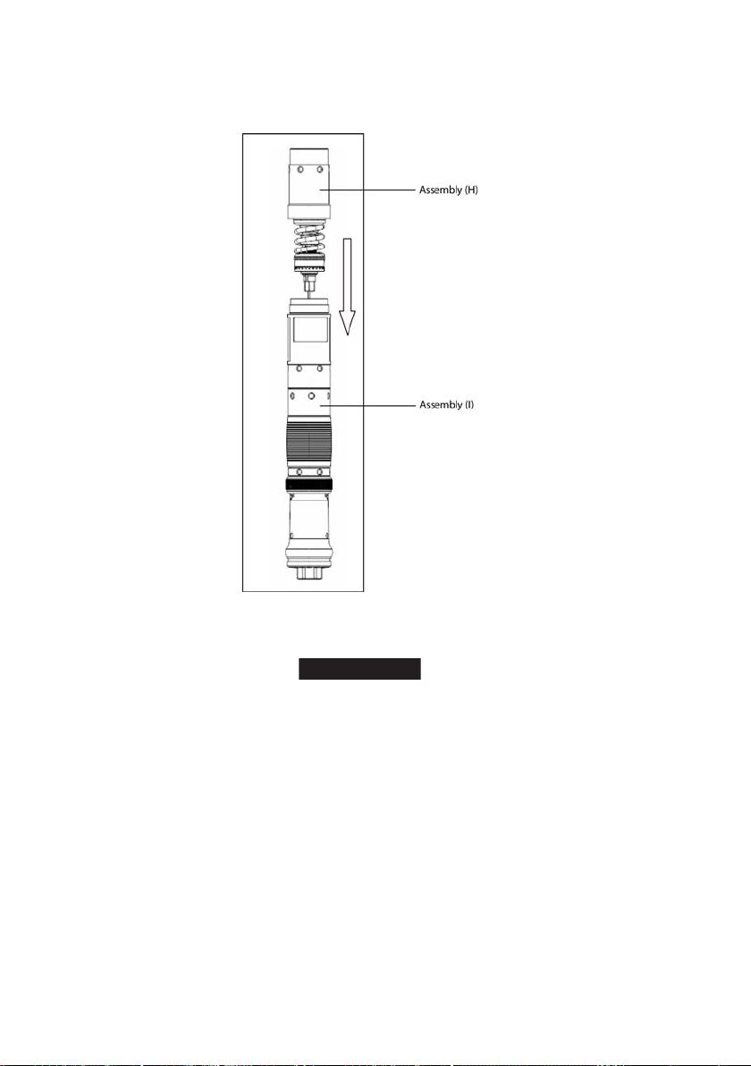
NOTICE
Guide other end of the Push Rod of Assembly (I) into Driver Shaft’s hole of the Assembly (H). Make sure that the push rod sits into the
1.
plunger’s hole placed in the driver shaft. Thread Gear Case with the Clutch Housing counterclockwise by hand.
Adjustment of Push Rod Gap
Pushrod length controls the shuto valve spacing in the backend housing of the tool. This spacing provides the proper air supply to the motor
and controls the timing of the clutch mechanism. for best operation of tool, please follow the instructions below.
Replacement of any component between the shuto valve and second stage gearing may change the tool’s operating valve gap. to
minimize down time, it is recommended to order a pushrod when replacing parts between these areas. During any assembly up to the
second stage, recertify correct gap using this procedure.
Note: Pushrods that are too short will decrease motor performance and may cause tool to stall. Also, pushrods that are too long may cause tool
to ratchet and not shuto. This is why pushrod length is so important.
Connect tool to air supply.
1.
with the second stage hand tight, turn the tool on and slowly unscrew the second stage from the clutch housing (clockwise) until tool stops.
2.
Note: If tool does not run when lever is initially pressed, pushrod is too short and needs to be replaced.
Release tool lever to reset air pressure. Repress lever and slowly tighten second stage until tool starts to rotate. from this point mark the
3.
housing to identify number of revolutions until it is hand tight (counterclockwise).
Note: Valve gap can be measured based on number of revolutions. 1 revolution = 1 mm of valve gap.
Verify proper valve gap for the tool:
4.
QA6 = 0.75 mm to 1.0 mm = 0.75 revolutions to 1.0 revolutions
QA8 = 1.0 mm to 1.25 mm = 1.0 revolutions to 1.25 revolutions
5. If the valve gap is less than the value in step 4, a new longer pushrod must be used and repeat steps 1-4.
6. If the valve gap is too large, take the actual number of revolutions measured in step 3 and subtract the maximum revolutions in step 4. Take
this value and subtract it from the pushrod length to get the length the pushrod needs to be cut.
7. Repeat steps 1-6 until you have correct length.
e.g. If the number of revolutions in step 3 comes out 1.5, then grind pushrod from 0.5 mm to 0.75 mm for QA6 tool and 0.25mm to 0.5mm
for QA8 tool.
8. Tighten second stage Gear Case with Clutch Housing counterclockwise to 70 Nm (52 Ft-Lb).
Page 85
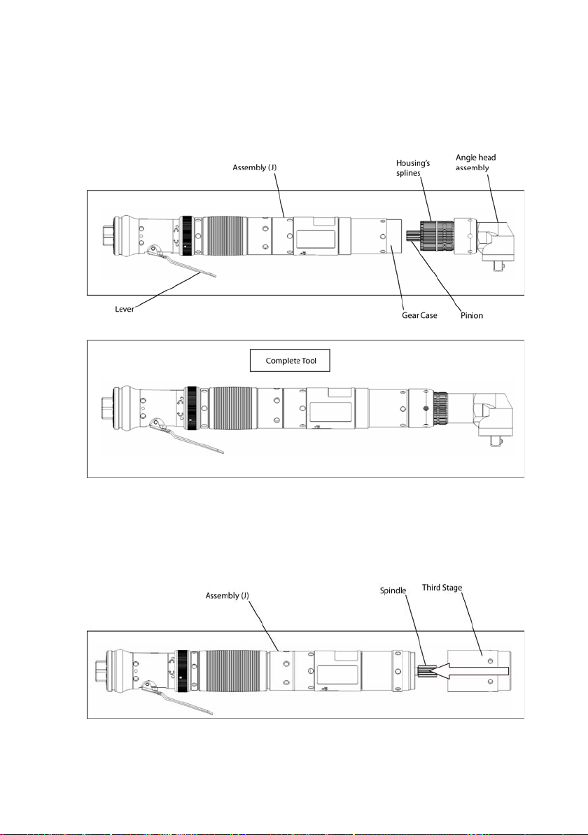
For Two Stages Models
Assembly Instructions for Angle Head Assembly/Float Spindle Assembly and Assembly (J)
Note: Orientate Angle Head Assembly wrt. Lever as shown in the view below.
Align Angle Head Assembly’s or Float Spindle Assembly’s Pinion gearing with Second stage’s spindle of Assembly (J). Also align Housing’s
1.
external splines with Gear case’s internal splines. Tighten Gear case with Coupling Nut mounted onto Angle head or Spindle clockwise by
hand rst and then to 90 Nm (66 Ft-Lb) clockwise by using spanner wrench and a torque wrench.
For Three Stages Models (QA8AA..150.., QA8AA..200.., QA8AA..225.., QA8AS..090.., QA8AS..115.., QA8AS..150..,
QA8AS..180..)
Assembly Instructions for Third Stage and Assembly (J)
Align Second stage’s spindle gears with Third stage’s gears. Thread second stage’s gear case with third stage’s gear case counterclockwise by
1.
hand rst and then to 90 Nm (66 Ft-Lb) counterclockwise.
Note: for ange tools, hold ange in vice.
16601056_ed1 85
Page 86
86 16601056_ed1
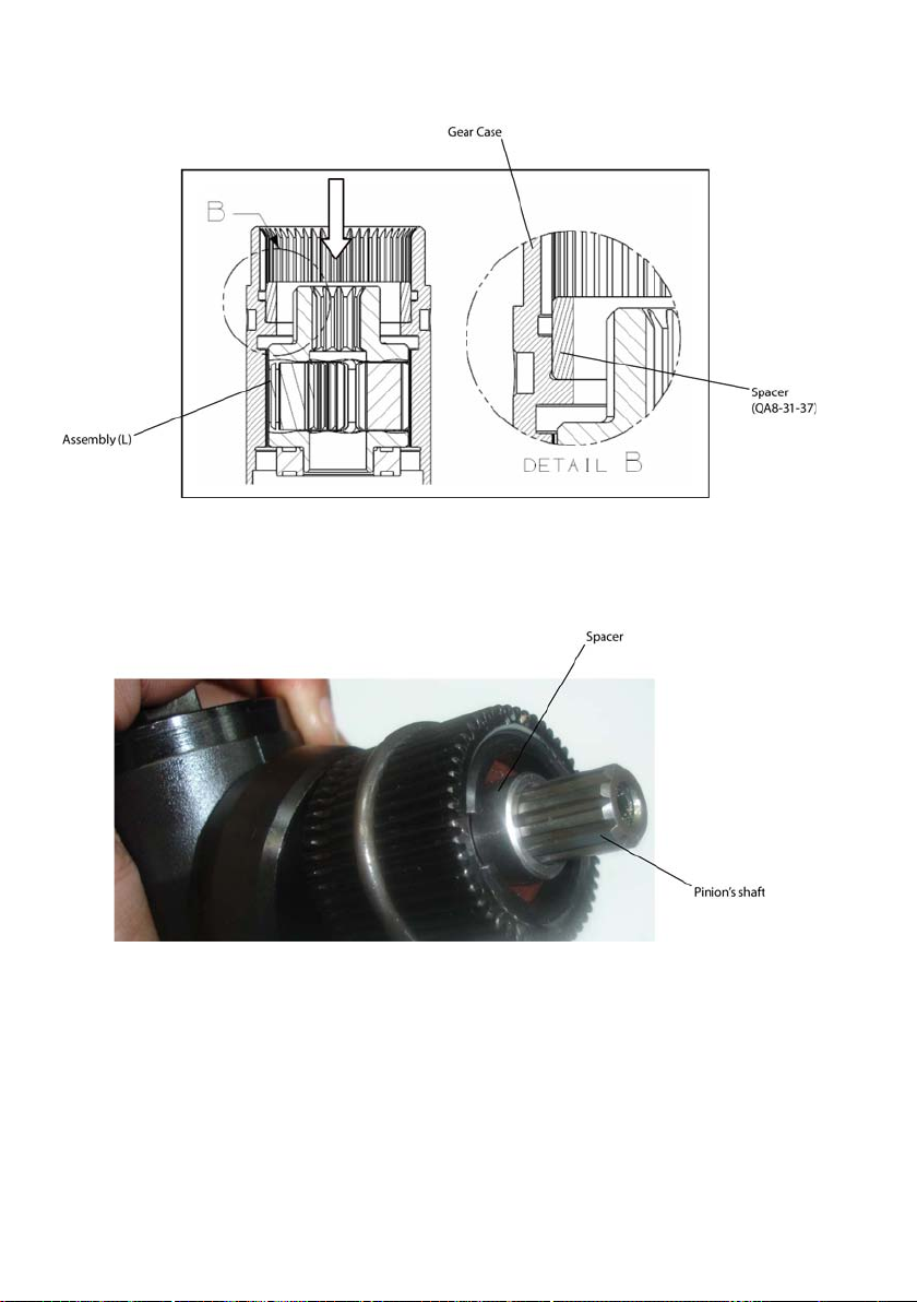
2. Mount Spacer (QA8-208) in Gear case (QA8-31-37) of the Third stage assembly (QA8-M37-4P29-1) for QAAA..150.. and QAAS..090.. models.
Assembly Instructions for Angle Head Assembly/Float Spindle Assembly and Assembly (L)
Mount Spacer (QA8S-442) on Float Spindle’s (160E4S8) Pinion shaft for QA8AS..115.., QA8AS..150.., and QA8AS..180..models.
1.
Mount Spacer (QA8A-442) on Angle Head’s (AA16S12) Pinion shaft for QA8AA..200.., QA8AA..225..models.
Mount Spacer (QA8-442) on Angle Head’s (GAA6S8) Pinion shaft for QAAA..150..model or Float Spindle’s (GE4S8) Pinion shaft for
QAAS..090.. models.
Page 87
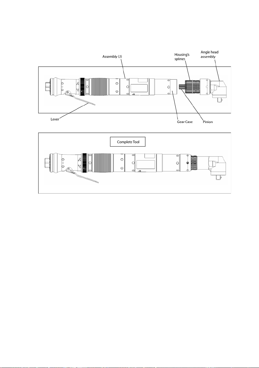
Note: Orientate Angle Head Assembly wrt. Lever as shown in the view below.
2. Align Angle Head Assembly’s or Float Spindle Assembly’s Pinion gearing with third stage’s spindle of Assembly (L). Also align Housing’s
external splines with Gear case’s internal splines. Tighten Gear case with Coupling Nut mounted onto Angle head or Spindle clockwise by
hand rst and then to 100 Nm (74 Ft-Lb) clockwise by using spanner wrench and a torque wrench.
16601056_ed1 87
Page 88
88 16601056_ed1
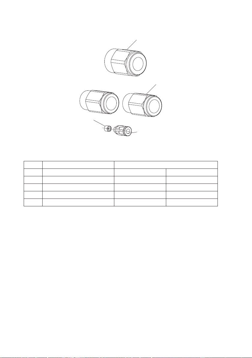
Remote Housing Kit Exploded Diagram
3
4
2
1
(Dwg. RG_45500832)
Remote Housing Kit Parts List
Item Part Description Part Number
Remote Housing Inlet Kit QA6-RB-K465 QA6-RN-K465
1 Set Screw,M5
2 Tube Fitting
3 Tube Fitting
4 Tube Fitting
Tooling Required
Standard tools and Products
Adjustable Spanner Wrench
•
Hex Keys Set
•
Page 89
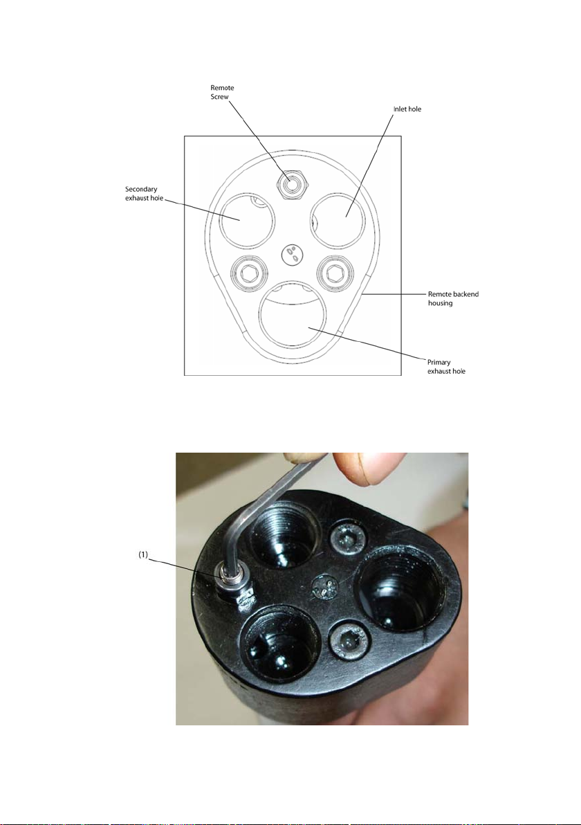
Assembly Instruction for Remote Housing Kit
Note: The holes illustrated in above picture are for forward direction only. for reverse direction, secondary exhaust becomes the inlet and the
inlet becomes the secondary exhaust.
Note: Set screw, M4 (1) is required if shut-o signal is not required.
1. Tighten Set Screw, M4 (1) onto Remote Screw in Remote Backend Housing clockwise using Hex key.
16601056_ed1 89
Page 90
90 16601056_ed1
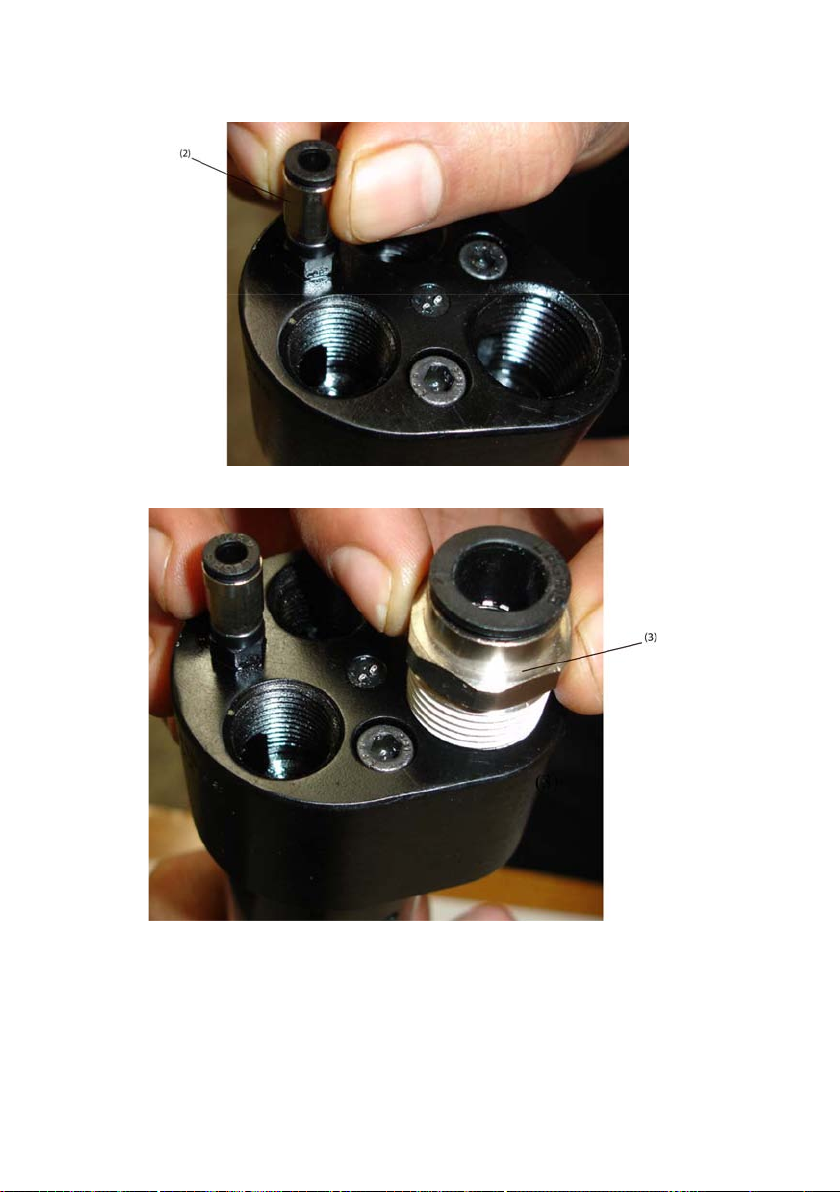
Note: Tube Fitting (2) is required to take shut-o signal from tool. In this case skip step (1)
1 (a). Tighten Tube tting (2) onto Remote Screw in Remote Backend Housing clockwise using Adjustable spanner wrench.
2. Tighten Tube Fitting (3) onto Primary exhaust hole threads in Remote Backend Housing clockwise using Adjustable spanner wrench.
Page 91
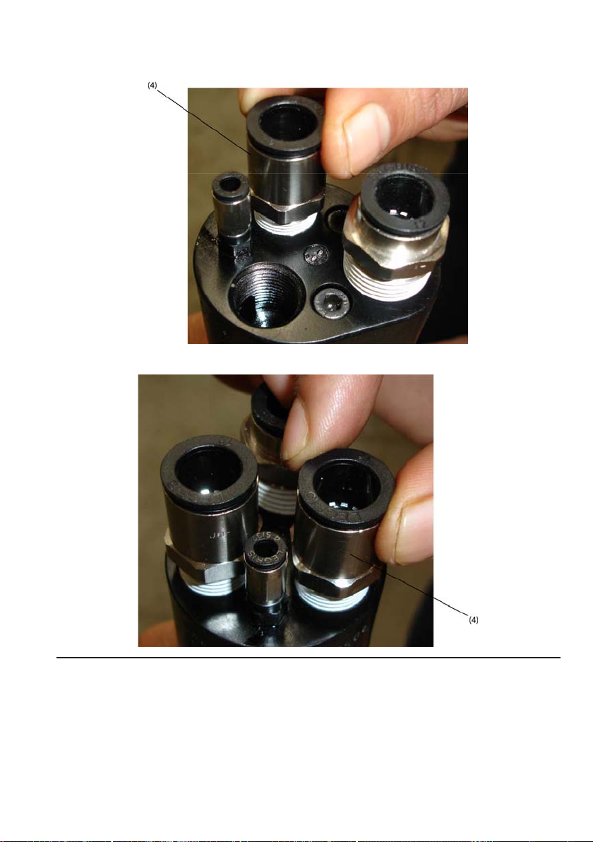
3. Tighten Tube Fitting (4) onto Inlet hole threads in Remote Backend Housing using spanner wrench.
4. Tighten Tube tting (4) onto Secondary exhaust hole threads in Remote Backend Housing using spanner wrench.
Related Documentation
for additional information refer to:
Air Angle Wrench, Screwdriver or Nut Runner Product Safety Information Manual 04585006.
Air Angle Wrench and Nut Runner Product Information Manual 16601064.
Air Angle Wrench and Nut Runner Parts Information Manual 16601072.
Manuals can be downloaded from www.irtools.com.
16601056_ed1 91
Page 92

Notes:
Page 93

Notes:
Page 94

www.irtools.com
© 2008 Ingersoll Rand Company
 Loading...