

Ingersoll-Rand HL1500K, HL4500K, HL6000K, HL1000K, HL1000KR Parts, Operation And Maintenance Manual
...
Form P6587
PARTS, OPERATION AND MAINTENANCE MANUAL
for
AIR CHAIN HOIST MODELS*
HL1000K HL1000KR HL1500K
1000 kg (1 ton) 1000 kg (1 ton) 1500 kg (1-1/2 ton)
Spark Resistant
HL2000K HL3000K HL4500K HL6000K
2000 kg (2 ton) 3000 kg (3 ton) 4500 kg (4-1/2 ton) 6000 kg (6 ton)
* Capacities of hoists are in metric tons (1 metric ton = 2,200 lbs.)
READ THIS MANUAL BEFORE USING THESE PRODUCTS. This manual
contains important safety, installation, operation and maintenance
information. Make this manual available to all persons responsible for
the operation, installation and maintenance of these products.
WARNING
Do not use this hoist for lifting, supporting, or transporting people or lifting or
supporting loads over people.
Always operate, inspect and maintain this hoist in accordance with American National
Standards Institute Safety Code (ASME B30.16) and any other applicable safety codes
and regulations.
Refer all communications to the nearest Ingersoll-Rand Material Handling Office or
Distributor.
Form P6587
Edition 6
May 1997
03531837
©
1997 Ingersoll-Rand Company
1

TABLE OF CONTENTS
Safety Information
Danger, Warning, Caution and Notice .............................................................................................................................................................. 3
Safety Summary ................................................................................................................................................................................................. 3
Safe Operating Procedures ................................................................................................................................................................................ 4
Warning Tags and Labels ................................................................................................................................................................................... 4
Specifications
Model Code Explanation ................................................................................................................................................................................... 6
Installation
Hoist Checks ...................................................................................................................................................................................................... 7
Hoist Mounting .................................................................................................................................................................................................. 7
Chain Container ................................................................................................................................................................................................. 8
Air System ..................................................................................................................... ..................................................................................... 8
Pendant Control Adjustments ............................................................................................................................................................................ 9
Storing the Hoist ................................................................................................................................................................................................ 9
Operation
Initial Operating Checks .................................................................................................................................................................................. 10
Hoist Controls .................................................................................................................................................................................................. 10
Pendant Controls.............................................................................................................................................................................................. 10
Pull Chain Control ........................................................................................................................................................................................... 11
Inspection
Records and Reports ........................................................................................................................................................................................ 12
Load Chain Reports ......................................................................................................................................................................................... 12
Frequent Inspection ......................................................................................................................................................................................... 12
Periodic Inspection .......................................................................................................................................................................................... 13
Hoists Not in Regular Use ............................................................................................................................................................................... 14
Inspection and Maintenance Report ................................................................................................................................................................ 15
Troubleshooting .............................................................................................................................................................................................. 16
Lubrication
General Lubrication ......................................................................................................................................................................................... 17
Maintenance
Load Chain Care .............................................................................................................................................................................................. 18
Initial Chain Installation .................................................................................................................................................................................. 19
Chain Replacement .......................................................................................................................................................................................... 22
Servicing the Filter and Strainer...................................................................................................................................................................... 23
Disassembly ..................................................................................................................................................................................................... 23
Cleaning, Inspection and Repair ..................................................................................................................................................................... 25
Assembly .......................................................................................................................................................................................................... 25
Load Test .......................................................................................................................................................................................................... 31
Assembly Drawings and Parts Lists..................................................................................................................................................... 33 - 61
Assembly Drawing and Parts List Table of Contents ..................................................................................................................................... 32
Parts Ordering Information
Return Goods Policy ........................................................................................................................................................................................ 62
Disposal ............................................................................................................................................................................................................ 62
Warranty Information ................................................................................................................................................................................... 63
Offices and Addresses.................................................................................................................................................................................... 64
2

SAFETY INFORMATION
DANGER
This manual provides important information for all personnel
involved with the safe installation, operation and proper
maintenance of this product. Even if you feel you are familiar
with this or similar equipment, you should read this manual
before operating the product.
Danger, Warning, Caution and Notice
Throughout this manual there are steps and procedures which, if
not followed, may result in a hazard. The following signal words
are used to identify the level of potential hazard.
Danger is used to indicate the presence
of a hazard which will cause severe
injury, death, or substantial property
damage if the warning is ignored.
WARNING
CAUTION
NOTICE
Warning is used to indicate the presence
of a hazard which can cause severe
injury, death, or substantial property
damage if the warning is ignored.
Caution is used to indicate the presence
of a hazard which will or can cause
minor injury or property damage if the
warning is ignored.
Notice is used to notify people of
installation, operation, or maintenance
information which is important but not
hazard-related.
Safety Summary
WARNING
• Do not use this hoist or attached equipment for lifting,
supporting, or transporting people or lifting or supporting
loads over people.
• Powered hoists are designed to provide a 5 to 1 safety
factor. The supporting structures and load-attaching devices
used in conjunction with this hoist must provide adequate
support to handle all hoist operations plus the weight of the
hoist and attached equipment. This is the customer’s
responsibility. If in doubt, consult a registered structural
engineer.
NOTICE
• Lifting equipment is subject to different regulations in each
country. These regulations may not be specified in this
manual.
The National Safety Council, Accident Prevention Manual for
Industrial Operations, Eighth Edition and other recognized
safety sources make a common point: Employees who work near
cranes or assist in hooking on or arranging a load should be
instructed to keep out from under the load. From a safety
standpoint, one factor is paramount: conduct all lifting
operations in such a manner that if there were an equipment
failure, no personnel would be injured. This means keep out
from under a raised load and keep out of the intended path of
any load.
Ingersoll-Rand Material Handling hoists are manufactured in
accordance with the latest ASME B30.16 standards.
The Occupational Safety and Health Act of 1970 generally
places the burden of compliance with the user, not the
manufacturer. Many OSHA requirements are not concerned or
connected with the manufactured product but are, rather,
connected with the final installation. It is the owner’s and user’s
responsibility to determine the suitability of a product for any
particular use. It is recommended that all applicable industry,
trade association, federal, state and local regulations be checked.
Read all operating instructions and warnings before operation.
Rigging: It is the responsibility of the operator to exercise
caution, use common sense and be familiar with proper rigging
techniques. See ASME B30.9 for rigging information,
American National Standards Institute, 1430 Broadway, New
York, NY 10018.
This manual has been produced by Ingersoll-Rand to provide
dealers, mechanics, operators and company personnel with the
information required to install, operate, maintain and repair the
products described herein.
It is extremely important that mechanics and operators be
familiar with the servicing procedures of these products, or like
or similar products, and are physically capable of conducting the
procedures. These personnel shall have a general working
knowledge that includes:
1. Proper and safe use and application of mechanic’s common
hand tools as well as special Ingersoll-Rand or
recommended tools.
2. Safety procedures, precautions and work habits established
by accepted industry standards.
Ingersoll-Rand cannot know of, or provide all the procedures
by which product operations or repairs may be conducted and
the hazards and/or results of each method. If operation or
maintenance procedures not specifically recommended by the
manufacturer are conducted, it must be ensured that product
safety is not endangered by the actions taken. If unsure of an
operation or maintenance procedure or step, personnel should
place the product in a safe condition and contact supervisors
and/or the factory for technical assistance.
3
SAFE OPERATING PROCEDURES
The following warnings and operating instructions have been
adapted in part from American National (Safety) Standard
ASME B30.16 and are intended to avoid unsafe operating
practices which might lead to injury or property damage.
Ingersoll-Rand recognizes that most companies who use hoists
have a safety program in force in their plants. In the event you
are aware that some conflict exists between a rule set forth in
this publication and a similar rule already set by an individual
company, the more stringent of the two should take precedence.
Safe Operating Instructions are provided to make an operator
aware of dangerous practices to avoid and are not necessarily
limited to the following list. Refer to specific sections in the
manual for additional safety information.
1. Only allow personnel instructed in safety and operation on
this product to operate and maintain the hoist.
2. Only operate a hoist if you are physically fit to do so.
3. When a “DO NOT OPERATE” sign is placed on the hoist
controls, do not operate the hoist until the sign has been
removed by designated personnel.
4. Read the manufacturer’s operating instructions before
operating the hoist.
5. Never lift a load greater than the rated capacity of the hoist
(unless for test purposes).
6. Never use the load chain as a sling.
7. Never operate the hoist with twisted, kinked, "capsized" or
damaged chain.
8. Be certain the load is properly seated in the saddle of the
hook.
9. Do not use load chain as a ground for welding. Do not
attach a welding electrode to a hoist or sling chain.
10. Do not use the up and down stops as a means of stopping a
hoist. The up and down stops are emergency devices only.
11. Do not leave a load suspended for extended periods.
12. Always stand clear of the load path.
13. Never use the hoist for lifting or lowering people, and
never stand on a suspended load.
14. Never carry loads over people.
15. Before each shift, check the hoist for wear or damage.
Check brakes, limit stops, etc.
16. Periodically, inspect the hoist thoroughly and replace worn
or damaged parts.
17. Follow the lubrication instructions.
18. Do not attempt to repair load chain or hooks. Replace them
when they become worn or damaged.
19. Never operate a hoist when the load chain is not centered
under the hook. Do not “side pull” or “yard”.
20. Always rig the hoist properly and carefully.
21. Ease the slack out of the load chain when starting a lift. Do
not jerk the hoist load.
22. Keep the load chain clean and well lubricated. Do not drag
the load chain or hook on the floor.
23. Be certain there are no objects in the way of a moving load.
24. Be certain the air supply is shut off before performing
maintenance on the hoist.
25. Do not swing a suspended load.
26. Keep the load block overhead when not in use.
27. After use, or when in a non-operational mode, the winch
should be secured against unauthorized and unwarranted
use.
28. Avoid collision or bumping of hoists.
29. Pay attention to the load at all times when operating a hoist.
30. Never splice a hoist chain by inserting a bolt between links
or by any other means.
31. Do not force a chain or hook into place by hammering, and
never insert the point of the hook into a chain link.
32. Do not allow the chain to be exposed to extremely cold
weather. Do not apply loads to a cold chain.
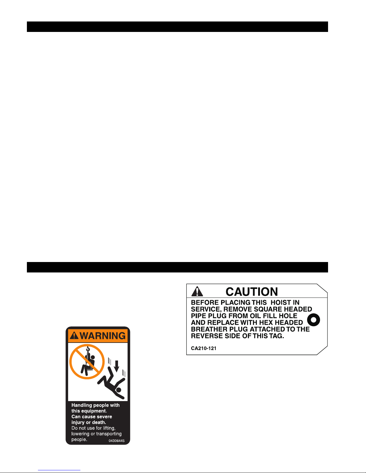
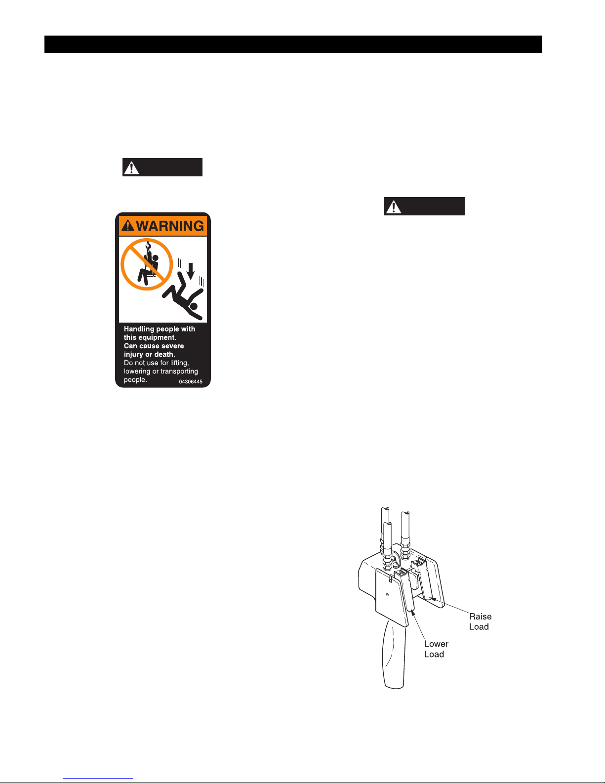
WARNING TAGS AND LABELS
Each hoist is supplied from the factory with the warning tags
and labels shown. If the tags or labels are not attached to your
hoist, order new tags or labels and install. See parts list in parts
section. Read and obey all warnings and other safety
information attached to this hoist. Tags and labels are not shown
actual size.
4
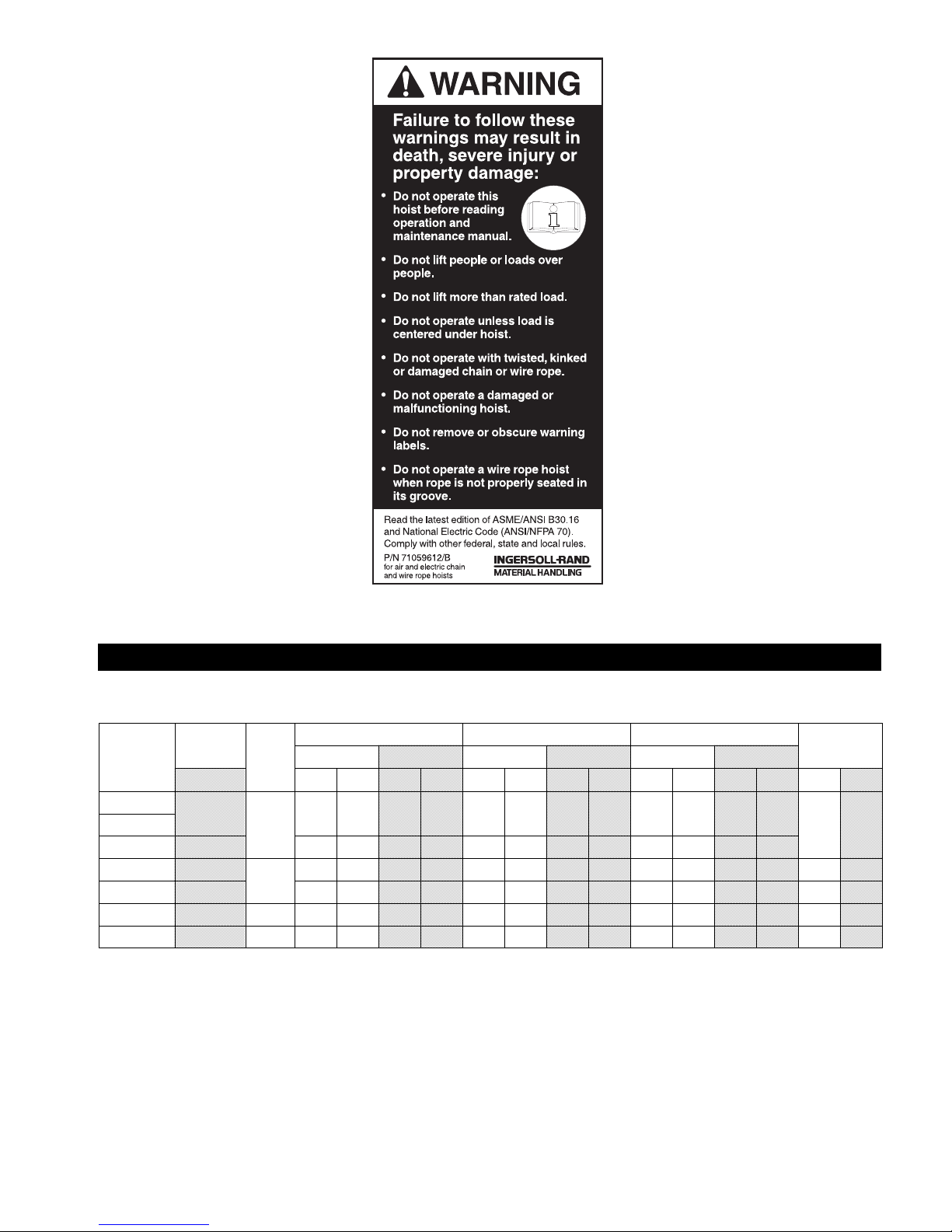
Table 1
SPECIFICATIONS
Hoist
Model No.
HL1000K
HL1500K 1500 16 26 4.9 7.9 22 22 6.7 6.7 28 16 8.5 4.9
HL2000K 2000
HL3000K 3000 8 13 2.4 4.0 11 11 3.4 3.4 14 8 4.3 2.4 129 58.5
HL4500K 4500 3 4.6 10 1.4 3.0 7.5 8.4 2.3 2.6 10.5 6.6 3.2 2.0 193 87.5
HL6000K 6000 4 3.5 7.6 1.0 2.3 5.8 6.2 1.8 1.9 8.4 4.8 2.6 1.5 248 112.5
Notes:
Based on hook mounted hoist with standard 10 ft (3 m) lift and one motor pendant control.
*
**
Performance figures based on 70 SCFM (1.96 cu m/min) at 90 psig (6.3 bar/630 kPa) air supply at hoist inlet. Pendant control
models use approximately 4 SCFM (0.11 cu m/min) more air.
Rated
Capacity
(kg) up down up down up down up down up down up down lb kgs
1000
No.
Chain
Falls
Speed with Rated Load Speed with Half Load Speed with No Load
fpm m/m fpm m/m fpm m/m
26 37 7.9 11.3 31 30 9.4 9.1 40 26 12.2 7.9
1
13 18 4.0 5.5 15 15 4.6 4.6 20 13 6.1 4.0 125 56.6
2
Hoist
Weight*
84 38.1HL1000KR
5

Model Code Explanation
Example: HL1000K-2C10-C6S H L 1000K - 2 C 10 - C 6 S
=
Series:
Chain Type:
L
Base Model:
1000K
1000KR = 1000 kg 1 metric ton (2,200 lbs) Spark Resistant
1500K = 1500 kg 1-1/2 metric tons (3,300 lbs)
2000K = 2000 kg 2 metric tons (4,400 lbs)
3000K = 3000 kg 3 metric tons (6,600 lbs)
4500K = 4500 kg 4-1/2 metric tons (10,000 lbs)
6000K = 6000 kg 6 metric tons (13,200 lbs)
Control:
0=
1=Pull Chain
2
3=
4=
Suspension (1):
A=
B=
C
R=
DA =
DD =
FXXA (2) =
FXXD (2) = Hand Geared Trolley (universal wheels “D” flange)
HA = Vane Motor Powered Trolley (universal wheels “A” flange)
HD = Vane Motor Powered Trolley (universal wheels “D” flange)
Length of Lift:
10
XX =
Lower Hook:
B=
C=
R=
Length of Pull Chain or Pendant Control Hose Drop: *
6
XX =
Options:
E=
M=
P=
S
U=
CE =
Notes:
H
=
Link
=
1000 kg 1 metric ton (2,200 lbs)
No control provided
=
Single Motor Pendant
Two Motor Pendant
Three Motor Pendant
Fixed Lug
Bullard Hook (self closing)
Swivel Steel Snap Hook
=
Bronze Snap Hook
Plain Rigid Trolley (universal wheels “A” flange)
Plain Rigid Trolley (universal wheels “D” flange)
Hand Geared Trolley (universal wheels “A” flange)
=
10 feet (3 metres) Standard
Specify Length
Bullard Hook (self closing)
Steel Snap Hook
Bronze Snap Hook
=
6 feet (1.8 metres) Standard
Specify Length (in feet)
Epoxy Paint
Manual Release Brake Kit
Piped Away Exhaust
Steel Chain Container
=
Fabric Chain Container
Compliance with European Machinery Directive: CE adds Pendant Emergency Stop, Main Air Shut Off Valve and
Overload Protection Device
(1) Refer to page 58 for Flange Adjustment.
(2) XX = Specify length of hand chain required. Example: "08" = 8 feet, standard.
(3) Order hose lengths in feet. Metric sizes listed for reference only.
6
NOTICE
WARNING
INSTALLATION
Prior to installing the hoist, carefully inspect it for possible
shipping damage.
Hoists are supplied fully lubricated from the factory. Lubrication
of the load chain is recommended before initial hoist operation.
CAUTION
• Owners and users are advised to examine specific, local or
other regulations, including American National Standards
Institute and/or OSHA Regulations which may apply to a
particular type of use of this product before installing or
putting hoist to use.
WARNING
• A falling load can cause injury or death. Before installing,
read “SAFETY INFORMATION”.
• The supporting structures and load-attaching devices used
in conjunction with this hoist must provide adequate support
to handle all hoist operations plus the weight of the hoist and
attached equipment. This is the customer’s responsibility. If
in doubt, consult a registered structural engineer.
Hoist Checks
Make certain your hoist is properly installed. A little extra time
and effort in so doing can contribute toward preventing
accidents and helping you get the best service possible.
Always make certain the supporting member from which the
hoist is suspended is strong enough to support the weight of the
hoist plus the weight of a maximum rated load plus a liberal
safety factor.
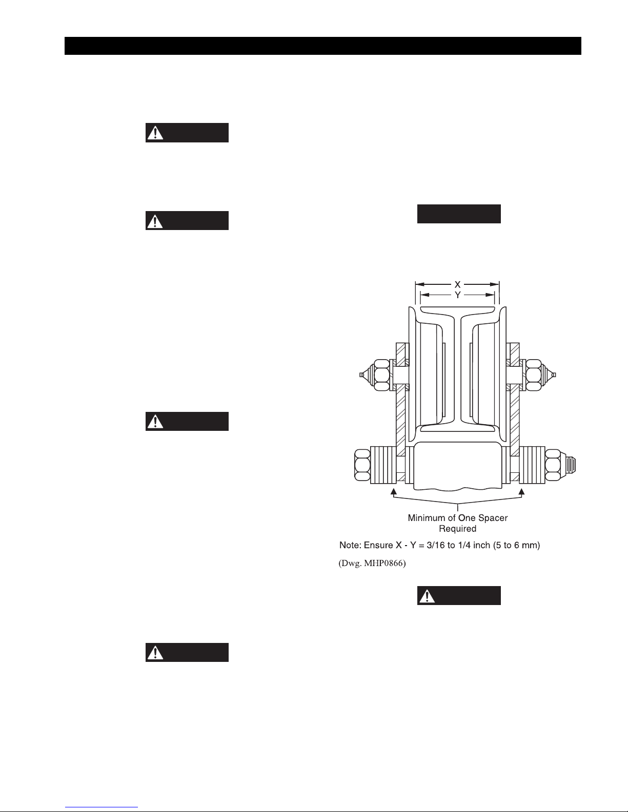
Trolley Mounted Hoist Installation
Refer to Dwg. MHP0866
When installing a trolley on a beam, measure the beam flange
and temporarily install the trolley on the hoist to determine the
exact distribution and arrangement of the spacers. The total
distance between the wheel flanges should be 3/16 to 1/4 inch (5
to 6 mm) greater than the width of the beam flange. The number
of spacers between the trolley side plate and the mounting lug
on the hoist must be the same in all four locations in order to
keep the hoist centered under the I-beam. The remaining spacers
must be equally distributed on the outside of the trolley side
plates.
• For specific information relating to trolley installation refer
to the manufacturers’ manual supplied with the trolley.
HLK Hoist Plain Rigid Trolley
CAUTION
• Before placing this hoist in service, remove square headed
pipe plug from oil fill hole and replace with hex headed
breather plug attached to caution tag CA210-121.
1. Remove the solid shipping plug located on top of the hoist
and install the attached breather plug prior to using the
hoist.
2. With the hoist placed in its normal level position check that
the gear case oil level is at the check plug on the side of the
gear box.
Hoist Mounting
Hook Mounted Hoist Installation
Place hook over mounting structure. Ensure hook is large
enough to properly fit on structure. Make sure hook latch is
engaged.
Ensure the supporting member rests completely within the
saddle of the hook and is centered directly above the hook
shank. Hoist must freely hang from hook without restriction.
CAUTION
• The supporting member must position on the saddle of the
hook. Ensure hoist does not tilt to one side or the other.
• A minimum of one adjusting spacer must be placed on the
outside of the trolley side plates. Ensure correct installation
as described in the parts, operation and maintenance manual
provided with the trolley.
Trolley bolt nuts (207) and (220) torque requirements:
On HL1000K, HL1500K, HL2000K and HL3000K hoists
torque to 150 ft lbs (203 Nm).
On HL4500K and HL6000K hoists torque to 250 ft lbs (339
Nm).
7
NOTICE
CAUTION
CAUTION
When installing the hoist and trolley on the beam, make certain
the side plates are parallel and vertical. After installation,
operate the trolley over the entire length of the beam with rated
load suspended 4 to 6 inches (100 to 150 mm) off the floor.
CAUTION
• To avoid an unbalanced load which may damage the
trolley, the hoist must be centered under the trolley.
NOTICE
• Trolley wheels ride on the top of the lower flange of the
beam.
Ensure beam stops are installed prior to operating hoist and
trolley.
Chain Container
Refer to Dwgs. TPC451-3 and MHP1029 and the
“MAINTENANCE” section for detailed assembly and
disassembly information.
NOTICE
• Make certain to adjust the container support such that the
chain container does not contact the load chain or hook.
• Operate the hoist to naturally pile chain into the chain
container. Piling the chain carelessly into the container by
hand may lead to kinking or twisting that may cause chain to
jam the hoist.
1. Check the chain container size to make sure the length of
load chain is within the capacity of the chain container.
Replace with a larger chain container, if required.
2. Attach the chain container to the hoist.
3. Run bottom block to lowest point and run hoist in up
direction to feed the chain back into the container.
WARNING
• Always use an air line filter and lubricator with an HLK
hoist.
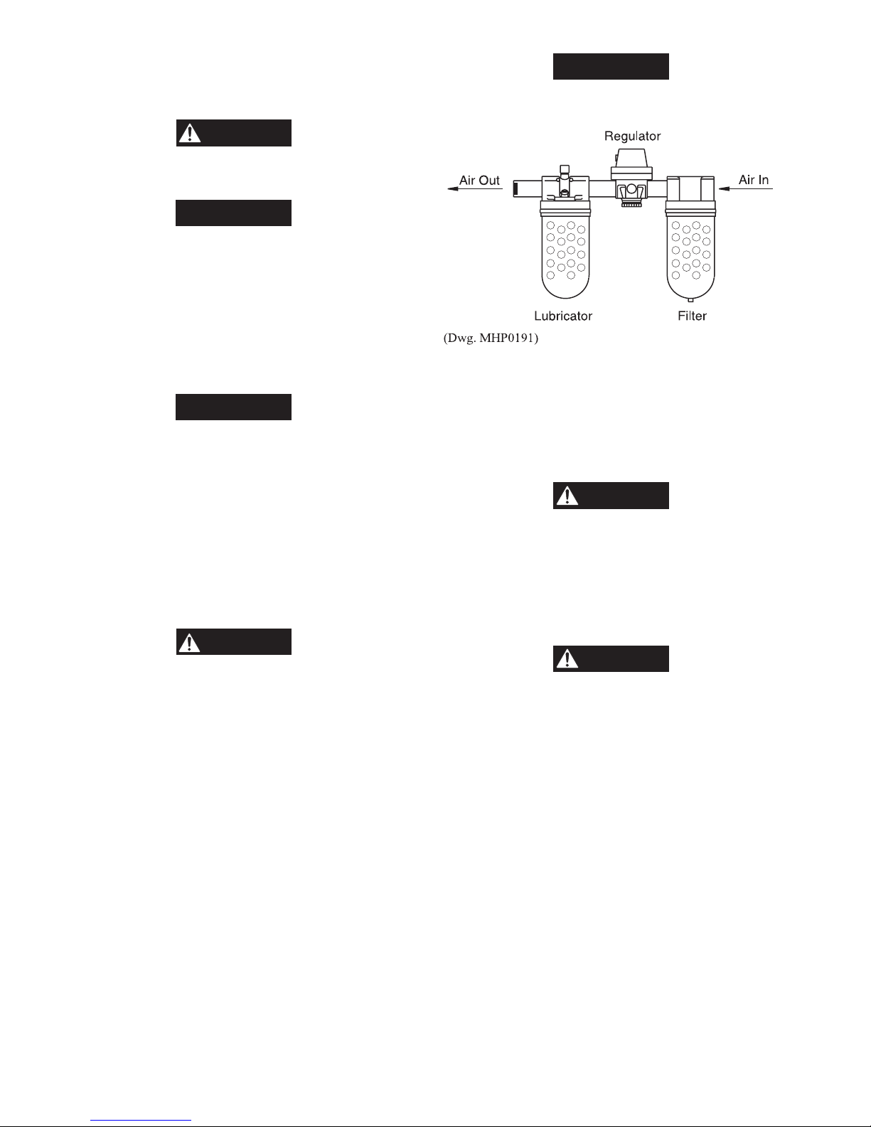
Air Line Lubricator
Refer to Dwg. MHP0191.
Always use an air line lubricator with these hoists. Use a
lubricator having an inlet and outlet at least as large as the inlet
on the hoist motor. Install the air line lubricator as close to the
air inlet on the hoist motor as possible. Refer to
“ACCESSORIES” in the parts section for the recommended
Filter-Lubricator-Regulator.
• Lubricator must be located no more than 10 ft (3 metres)
from the hoist motor.
• Shut off air supply before filling air line lubricator.
The air line lubricator should be replenished daily and set to
provide lubrication at a minimum rate of 1 to 3 drops per minute
adjusted at maximum hoist speed, of SAE 10W oil or a good
grade of hydraulic oil.
• Disconnect the hoist from the air supply before installing a
chain container kit.
Air System
The supply air must be clean, lubricated and free from water or
moisture. A minimum air supply of 70 scfm (1.96 cu. m/m) at 90
psig (6.3 bar/630 kPa) at the hoist motor inlet is required, during
operation to provide rated hoist performance.
Air Lines
The inside diameter of the hoist air supply lines must not be
smaller than 1/2 in (13 mm) for up to 12 ft (4 m) lengths and 3/4
in (19 mm) for up to 50 ft (15 m) lengths between the air supply
and the hoist. Contact the factory for recommended air line sizes
for distances greater than 50 ft (15 m). Before making final
connections, all air supply lines should be purged with clean,
moisture free air before connecting to unit inlet. Supply lines
should be as short and straight as installation conditions will
permit. Long transmission lines and excessive use of fittings,
elbows, tees, globe valves, etc. cause a reduction in pressure due
to restrictions and surface friction in the lines. Fittings used at
the inlet of the hoist must have at least a 3/8 in (10 mm) air
passage. Use of smaller fittings will reduce performance.
• Do not use automotive type detergent oil. Detergents will
delaminate the motor vanes and cause premature failure.
Air Line Filter
Refer to Dwg. MHP0191
It is recommended that an air line strainer/filter be installed as
close as practical to the motor air inlet port to prevent dirt from
entering the motor. The strainer/filter should provide 10 micron
filtration and include a moisture trap. Clean the strainer/filter
monthly to maintain its operating efficiency. Refer to
"ACCESSORIES" in the parts section for the recommended
Filter-Lubricator-Regulator.
Moisture in Air Lines
Moisture that reaches the air motor through the supply lines is
the chief factor in determining the length of time between
service overhauls. Moisture traps can help to eliminate moisture.
Other methods, such as an air receiver which collects moisture
before it reaches the motor or, an aftercooler at the compressor
that cools the air prior to distribution through the supply lines,
are also helpful.
The swivel inlet assembly (includes items 23 through 24C) must
be installed on the hoist. Failure to do so may result in a hoist
malfunction.
8
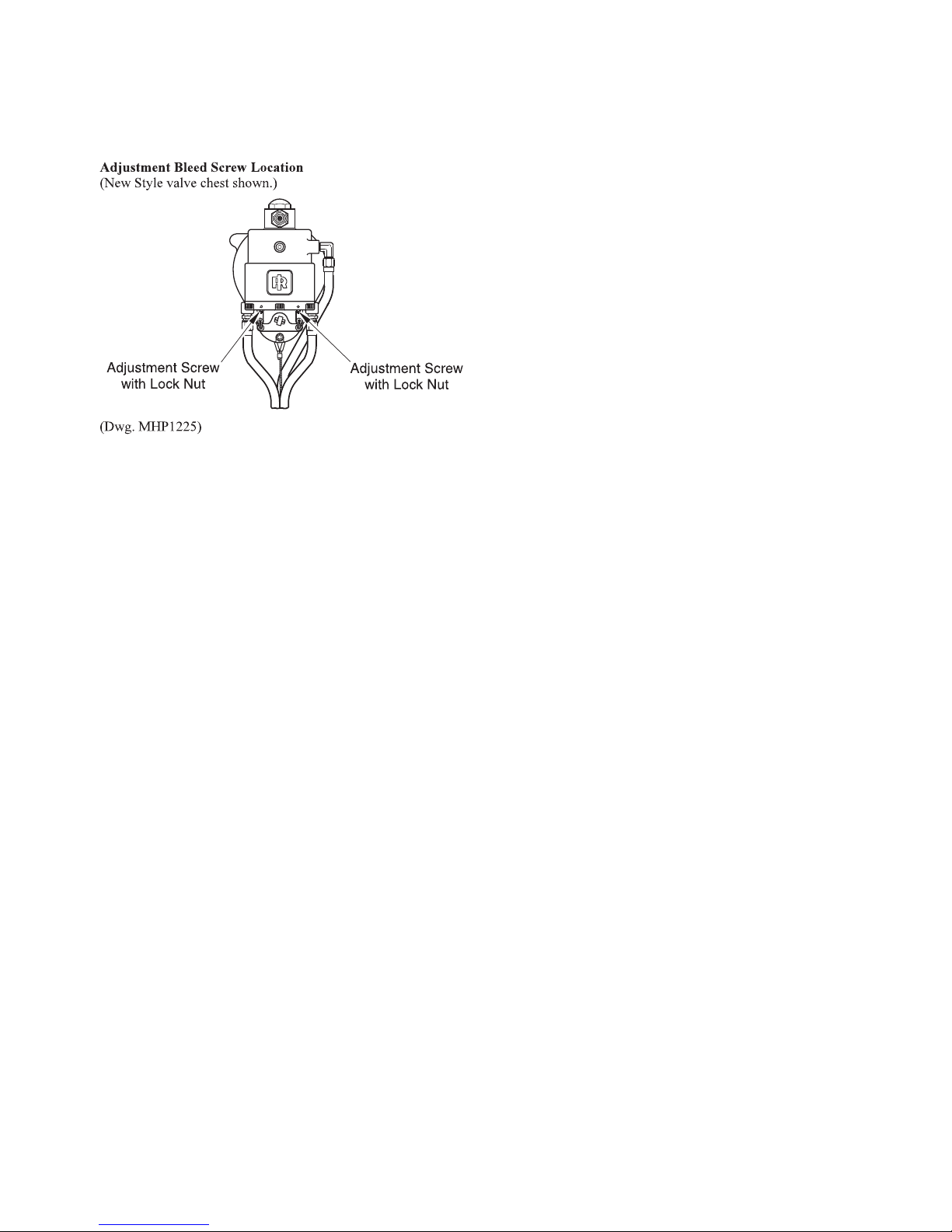
Pendant Control Adjustments
The bleed adjustment screws (19) or (336 [old style]) used on
hoists with a pendant control are factory adjusted to provide
optimum control at 90 psig (6.3 bar/630 kPa) air pressure. If the
hoist is used with other air supply pressures, the bleed
adjustment screws may require readjustment.
For maximum performance and control, adjust the bleed screws
(19) or (336 [old style]) as follows:
1. Loosen the adjustment screw locknut (21) or (337 [old
style]).
2. Turn the adjustment screw (19) or (336 [old style])
counterclockwise approximately one third (1/3) of a turn.
3. Fully depress the pendant throttle lever (165) and hold in
depressed position. Turn the adjustment screw clockwise
until the piston rod fully retracts. This adjustment will
provide a good balance of spotting control and maximum
hoist speed. If better spotting control is desired, slowly
back out the adjustment screw a little at a time until the
spotting control is suitable.
4. When adjustment is complete, hold the adjustment screw in
position and tighten the adjustment screw locknut (21) or
(337 [old style]).
5. Repeat steps 1 through 4 for opposite pendant throttle
lever.
Storing the Hoist
1. Always store the hoist in a no load condition.
2. Wipe off all dirt and water.
3. Oil the load chain, hook pins and hook latch.
4. Place in a dry location.
5. Plug hoist air inlet port.
6. Before returning hoist to service follow instructions for
‘Hoists not in Regular Service’ in the “INSPECTION”
section.
9
OPERATION
WARNING
The four most important aspects of hoist operation are:
1. Follow all safety instructions when operating hoist.
2. Allow only people instructed in safety and operation on this
product to operate hoist.
3. Subject each hoist to a regular inspection and maintenance
procedure.
4. Be aware of the hoist capacity and weight of load at all
times.
WARNING
• Do not use this hoist for lifting, supporting or transporting
people or lifting or supporting loads over people.
Operators must be physically competent. Operators should have
no health condition which might affect their ability to react, and
they must have good hearing, vision and depth perception. The
hoist operator must be carefully instructed in his duties and must
understand the operation of the hoist, including a study of the
manufacturer’s literature. The operator must be aware of proper
methods of hitching loads and should have a good attitude
regarding safety. It is the operator's responsibility to refuse to
operate the hoist under unsafe conditions.
Initial Operating Checks
Hoists are tested for proper operation prior to leaving the
factory. Before the hoist is placed into service the following
initial operating checks should be performed.
1. After installation of trolley mounted hoists, check to ensure
the hoist is centered below the trolley.
2. Check for air leaks in the supply hose and fittings to
pendant, and from pendant to manifold.
3. When first running the hoist or trolley motors a small
amount of light oil should be injected into the inlet
connection to allow good lubrication.
4. When first operating the hoist and trolley it is
recommended that the motors be driven slowly in both
directions for a few minutes.
5. Operate the trolley along the entire length of the beam.
6. Inspect hoist and trolley performance when raising, moving
and lowering test load(s). Hoist and trolley must operate
smoothly and at rated specifications prior to being placed in
service.
7. Check that trolley (if equipped) and hook movement is the
same direction as arrows or information on the pendant
control.
8. Raise and lower a light load to check operation of the hoist
brake.
9. Check hoist operation by raising and lowering a load equal
to the rated capacity of the hoist 4 to 6 inches (100 to 150
mm) off the floor.
10. Check operation of limit devices.
11. Check to see that the hoist is directly over the load. Do not
lift the load at an angle (side pull or “yard”).
12. Check to see that the hoist is securely connected to the
overhead crane, monorail, trolley or supporting member.
13. Check to see that the load is securely inserted in the hook,
and that the hook latch is engaged.
• The hook latch is intended to retain loose slings or devices
under slack conditions. Hook latches are not intended to be
an antifouling device, so caution must be used to prevent the
latch from supporting any of the load.
Hoist Controls
Pendant Controls
The HLK hoist can be supplied with an optional manual pull
chain control or a one, two or three function pendant depending
on application. For detailed information on these products refer
to Ingersoll-Rand Manual Form Number P6778 or contact your
nearest distributor or the factory.
Operation of the hoist is the same for all pendants listed in this
section:
1. To lift a load, depress the hoist pendant raise lever.
2. To lower a load depress the hoist pendant lower lever.
3. To throttle lift or lowering speed, regulate the amount the
pendant lever is depressed. Depress lever completely for
maximum speed; depress lever partially for slower speeds.
4. To stop lift or lowering function, release the lever. Lever
will spring return to off and hoist motor will stop.
Single Function, Two Lever Pendant
Refer to Dwg. MHP0427.
The two lever pendant is the standard pendant supplied with the
HLK and is designed to provide hoist operation only. Hoist
operation must correspond to the directions indicated by the
arrows located on the pendant levers.
(Dwg. MHP0427)
10
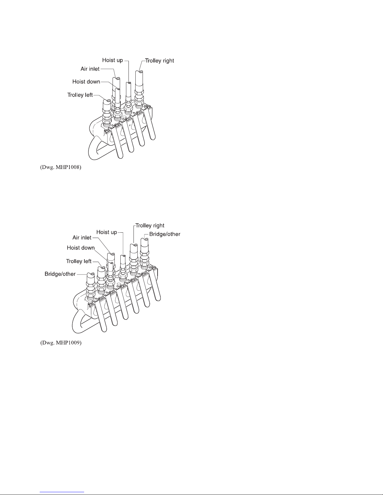
Two Function, Four Lever Pendant
The four lever pendant is designed to provide a single station for
control of hoist and trolley operations.
Refer to Dwg. MHP1008 for pendant lever function and hose to
component connections.
Three Function, Six Lever Pendant
The six lever pendant is designed to provide a single station for
control of the hoist, the trolley and a third related component
(bridge/runway) operation.
Refer to Dwg. MHP1009 for pendant lever function and hose to
component connections.
Pull Chain Control
The pull chain provides the operator with a local hoist operating
station. The following operating directions are as viewed from
the motor end of hoist, facing the pull chains.
1. To lift a load pull down on the right pull chain.
2. To lower a load pull down on the left pull chain.
3. To throttle lift or lowering speed regulate the distance the
pull chain travels. Pull chain to full travel for maximum
speed; pull chain partially for slower speeds.
4. To stop lift or lowering of load, release the pull chain.
Hoist motor will stop.
11
INSPECTION
WARNING
• All new, altered or modified equipment should be inspected
and tested by personnel instructed in safety, operation and
maintenance of this equipment to ensure safe operation at
rated specifications before placing equipment in service.
• Never use a hoist that inspection indicates is damaged.
Frequent and periodic inspections should be performed on
equipment in regular service. Frequent inspections are visual
examinations performed by operators or service personnel and
include observations made during routine equipment operation.
Periodic inspections are thorough inspections conducted by
personnel trained in the safety, operation and maintenance of
this equipment. ASME B30.16 states inspection intervals
depend upon the nature of the critical components of the
equipment and the severity of usage.
The inspection intervals recommended in this manual are based
on intermittent operation of the hoist eight hours each day, five
days per week, in an environment relatively free of dust,
moisture and corrosive fumes. If the hoist is operated almost
continuously or more than eight hours each day, more frequent
inspections will be required.
Careful inspection on a regular basis will reveal potentially
dangerous conditions while still in the early stages, allowing
corrective action to be taken before the condition becomes
dangerous.
Deficiencies revealed through inspection, or noted during
operation, must be reported to designated personnel trained in
safety, operation and maintenance of this equipment. A
determination as to whether a condition constitutes a safety
hazard must be decided, and the correction of noted safety
hazards accomplished and documented by written report before
placing the equipment in service.
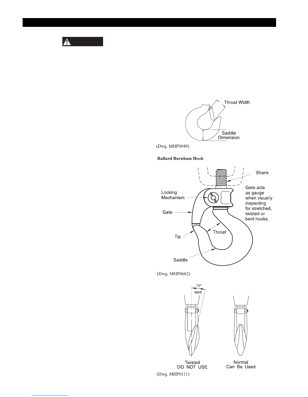
2. HOOKS. Check for wear or damage, increased throat
width, bent shank or twisting of hook. Replace hooks
which exceed the throat opening and/or saddle dimension
discard widths specified in Table 2 (refer to Dwg.
MHP0040) or exceed a 10° twist (refer to Dwg.
MHP0111). If the hook latch snaps past the tip of the hook,
the hook is sprung and must be replaced. Replace Bullard
Burnham hooks if the gate no longer contacts the hook tip.
Refer to Dwg. MHP0662. Refer to the latest edition of
ASME B30.10 “HOOKS” for additional information.
Check hook support bearings for lubrication or damage.
Ensure they swivel easily and smoothly.
Records and Reports
Inspection records, listing all points requiring periodic
inspection should be maintained for all load bearing equipment.
Written reports, based on severity of service, should be made on
the condition of critical parts as a method of documenting
periodic inspections. These reports should be dated, signed by
the person who performed the inspection, and kept on file where
they are readily available for review.
Load Chain Reports
Records should be maintained documenting the condition of
load chain removed from service as part of a long-range load
chain inspection program. Accurate records will establish a
relationship between visual observations noted during frequent
inspections and the actual condition of the load chain as
determined by periodic inspection methods.
Frequent Inspection
On hoists in continuous service, frequent inspection should be
made by operators at the beginning of each shift. In addition,
visual inspections should be conducted during regular operation
for any damage or evidence of malfunction (such as abnormal
noises).
1. OPERATION. Check for visual signs or abnormal noises
(grinding etc.) which could indicate a potential problem.
Make sure controls function properly and return to neutral
when released. Check load chain feed through the hoist and
bottom block. If chain binds, jumps, is excessively noisy or
"clicks", clean and lubricate the chain. If problem persists,
replace the chain. Do not operate the hoist until all
problems have been corrected.
12
3. UPPER AND LOWER LIMIT DEVICE. Test operation
with no load slowly to both extremes of travel. Upward
travel must stop when the bottom block or stop ring on
chain hits hoist limit arm. Downward travel must stop when
the loop at the unloaded end of the chain decreases and
activates the limit arm.
4. AIR SYSTEM. Visually inspect all connections, fittings,
hoses and components for indication of air leaks. Repair
any leaks found. Check and clean the filter in the inlet stud
(24) and the inlet strainer (24C) if equipped.
5. CONTROLS. During operation of hoist, verify response to
pendant, or pull chain, is quick and smooth. Ensure that the
controls return to neutral and hoist operation stops when
released. If hoist responds slowly or movement is
unsatisfactory, do not operate hoist until all problems have
been corrected.
6. HOOK LATCH. Make sure the hook latch or gate is
present and operating. Replace if necessary.
CAUTION
• Do not use hoist if hook latch or gate is missing or damaged.
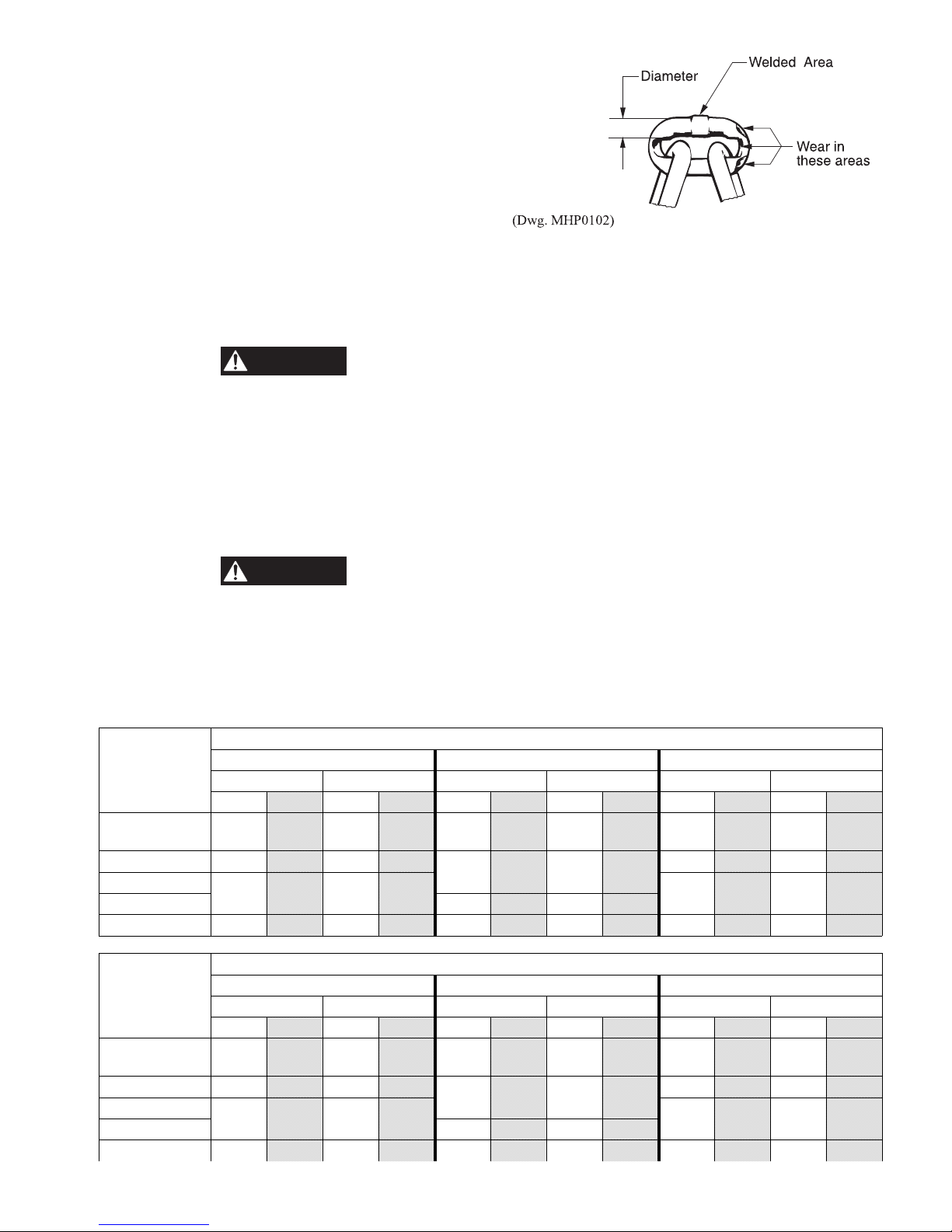
7. LOAD CHAIN. Examine each link for bending, cracks in
weld areas or shoulders, traverse nicks and gouges, weld
splatter, corrosion pits, striation (minute parallel lines) and
chain wear, including bearing surfaces between chain links
(refer to Dwg. MHP0102). Replace a chain that fails any of
the inspections. Check chain lubrication and lubricate if
necessary. Refer to ‘Load Chain’ in “LUBRICATION”
section.
CAUTION
• The full extent of load chain wear cannot be determined by
visual inspection. At any indication of load chain wear
inspect chain and chain wheel in accordance with
instructions in ‘Load Chain’ listed in “Periodic Inspection”
section.
8. LOAD CHAIN REEVING. Ensure welds on standing links
are away from the powered chain wheel. Reinstall chain if
necessary. On hoists with multiple chain falls, make sure
load chain is not capsized, twisted or kinked. Adjust as
required.
Periodic Inspection
Frequency of periodic inspection depends on the severity of
usage:
NORMAL HEAVY SEVERE
yearly semiannually quarterly
Disassembly may be required for HEAVY or SEVERE usage.
Keep accumulative written records of periodic inspections to
provide a basis for continuing evaluation.
Inspect all the items in "Frequent Inspection". Also inspect the
following:
1. FASTENERS. Check all rivets, split pins, capscrews and
nuts. Replace if missing or tighten if loose.
2. ALL COMPONENTS. Inspect for wear, damage,
distortion, deformation and cleanliness. If external evidence
indicates the need, disassemble. Check gears, shafts,
bearings, sheaves, chain guides, springs and covers.
Replace worn or damaged parts. Clean, lubricate and
reassemble.
Table 2
Hoist
Model
HL1000K and
HL1500K
HL2000K
HL3000K
HL4500K
HL6000K
Hoist
Model
HL1000K and
HL1500K
HL2000K
HL3000K
HL4500K
HL6000K
Throat Width (with Latch installed)
Standard Bronze Bullard Burnham
New Hook Discard Hook New Hook Discard Hook New Hook Discard Hook
in mm in mm in mm in mm in mm in mm
1.12 28.4 1.21 30.7 1.06 26.9 1.14 29.0 1.37 34.8 1.48 37.6
1.06 26.9 1.14 29.0
1.50 38.1 1.62 41.1 1.87 47.5 2.02 51.3
1.75 44.5 1.89 48.0 2.75 69.9 2.97 75.4 3.00 76.2 3.24 82.3
Standard Bronze Bullard Burnham
New Hook Discard Hook New Hook Discard Hook New Hook Discard Hook
in mm in mm in mm in mm in mm in mm
1.12 28.4 1.21 30.7 1.44 36.6 1.56 39.6 1.34 34.0 1.45 36.8
1.44 36.6 1.56 39.6
1.81 46.0 1.95 49.5 1.87 47.5 2.02 51.3
2.25 57.2 2.43 61.7 2.97 75.4 3.21 81.5 2.75 69.9 2.97 75.4
1.50 38.1 1.62 41.1
1.75 44.5 1.89 48.0
Saddle Dimension
1.81 46.0 1.95 49.5
2.25 57.2 2.43 61.7
1.50 38.1 1.62 41.1
1.50 38.1 1.62 41.1
13
3. HOOKS. Inspect hooks carefully for cracks using magnetic
particle or other suitable nondestructive method. Inspect
hook retaining parts. Tighten or repair, if necessary.
4. LOAD CHAIN WHEELS. Check for damage or excessive
wear. Replace if necessary. Observe the action of the load
chain feeding through the hoist. Do not operate a hoist
unless the load chain feeds through the hoist and hook
block smoothly and without audible clicking or other
evidence of binding or malfunctioning.
5. MOTOR. If performance is poor, disassemble the motor
and check for wear or damage to bearings and shafts. The
parts should be cleaned, lubricated and reassembled.
Replace worn or damaged parts.
6. BRAKE. Raise a load equal to the rated capacity of the
hoist 4 to 6 inches (100 to 150 mm) off the floor. Verify
hoist holds the load without drift. If drift occurs,
disassemble. Remove brake discs as described in the
“MAINTENANCE” section. Check and clean the brake
parts each time the hoist is disassembled. Replace the brake
discs if the thickness is less than 0.090 inch (2.29 mm).
7. SUPPORTING STRUCTURE. Check for distortion, wear
and continued ability to support load.
8. TROLLEY (if equipped). Check that the trolley wheels
track the beam properly and clearance between each wheel
flange and beam is correct, 3/32 to 1/8 in. (2 to 3 mm).
Check that wheels and beam are not excessively worn.
Inspect side plates for spreading due to bending. Do not
operate the hoist until any problems have been determined
and corrected.
9. LABELS AND TAGS. Check for presence and legibility.
Replace if necessary.
10. LOAD CHAIN END ANCHORS. Ensure both ends of load
chain are securely attached. Secure if loose, repair if
damaged, replace if missing.
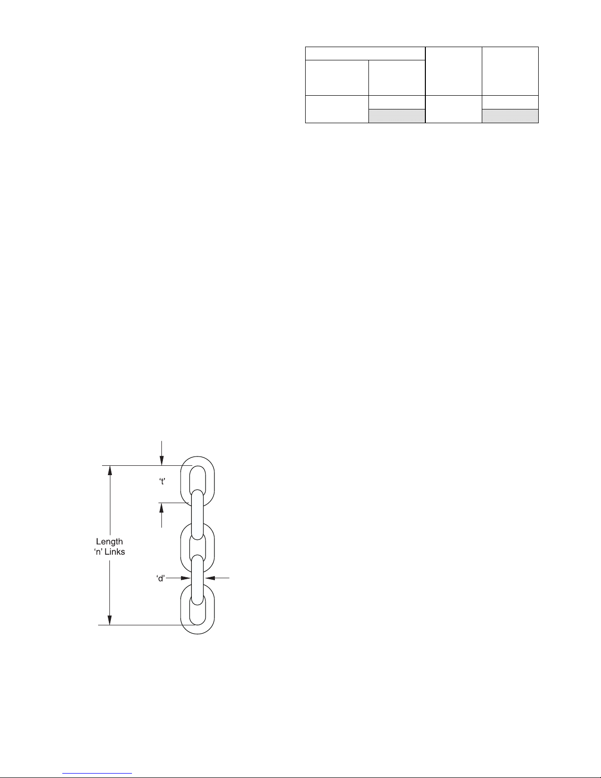
11. LOAD CHAIN. Measure the load chain for wear over a
five link section as shown in Dwg. MHP1291. Pay
particular attention to the most frequently reeved links.
When any five links in the working length reaches or
exceeds the discard length shown in Table 3, replace the
entire chain. Always use a genuine Ingersoll-Rand
Material Handling replacement chain.
Table 3 Load Chain Length
Dimensions Of Link
Nominal Wire
Diameter
(d)
3/8
Zinc plated load chain is standard on HLK hoists built after
January 1996. Always use stainless steel load chain on
HL1000KR Spark Resistant Hoists.
12. CHAIN CONTAINER. Check for damage or excessive
wear and that chain container is securely attached to the
hoist. Secure or replace if necessary.
13. LIMIT ASSEMBLY. Check throttle lever moves freely. To
limit hook downward travel the loop in the slack chain side
must contact the throttle lever. To limit hook upward travel
the bottom hook block, or stop ring, must contact the
throttle lever.
To test “UP” and “DOWN” travel limits first run hoist
slowly with no load to verify proper function. Repeat test at
full speed with no load to verify proper function. On Hoist
Models HL4500K and HL6000K the throttle lever (35)
may require minor adjustment to provide adequate
clearance with the upper suspension block.
Pitch
(t)
1.012 in
25.7 mm 131.4 mm
Number Of
Links
(n)
5
Discard
Length
(n)
Links
5.175 in
Hoists Not in Regular Use
1. A hoist which has been idle for a period of one month or
more, but less than one year, should be given an inspection
conforming with the requirements of “Frequent Inspection”
prior to being placed into service.
2. A hoist which has been idle for a period of more than one
year should be given an inspection conforming with the
requirements of “Periodic Inspection” prior to being placed
into service.
3. Standby hoists should be inspected at least semiannually in
accordance with the requirements of “Frequent Inspection”.
In abnormal operating conditions hoists should be
inspected at shorter intervals.
(Dwg. MHP1291)
14
INSPECTION AND MAINTENANCE REPORT
Ingersoll-Rand HLK Air Chain Hoist
Model Number: Date:
Serial Number: Inspected by:
Reason for Inspection: (Check Applicable Box)
1. Scheduled Periodic Inspection:
____ Quarterly ____Semiannually ____Yearly
2. Discrepancy(ies) noted during Frequent Inspection
3. Discrepancy(ies) noted during maintenance
4. Other: ____________________________
Refer to the Parts, Operation and Maintenance Manual “INSPECTION” section for general inspection criteria. Refer to appropriate National Standards and
Codes of practice. If in doubt about an existing condition contact the nearest Ingersoll-Rand Distributor or the factory for technical assistance.
Operating Environment:
_____ Normal _____ Heavy _____ Severe
COMPONENT
Fasteners
Gears
Shafts
Bearings - - Load Bearing Sheaves
Chain Guides
Springs - - Covers
Hooks:
Actual Hook Throat Width: __________ inches / __________ mm (Refer to Table 2 for minimum/maximum acceptable widths.)
Top
Hook Twist - - - (maximum 10%)
Hook Crack Test Method Used: _____ Dye Penetrant _____ Magnetic Particle _____ Other: ____________________
Actual Hook Throat Width: __________ inches / __________ mm (Refer to Table 2 for minimum/maximum acceptable widths.)
Bottom
Hook Latch (Standard) - - Hook Gate (Bullard) - - Brakes
(10% Load Test)
Brakes
(Visual Inspection)
Tail Pin (End Anchor)
Load Chain: - - -
Supporting Structure
Labels and Tags - - Other Components
(list in NOTES section)
Hook Twist - - - (maximum 10%)
Hook Crack Test Method Used: _____ Dye Penetrant _____ Magnetic Particle _____ Other: ____________________
Working length(s) maximum wear: __________ inches / __________ mm (Refer to Table 3)
CONDITION
Pass Fail Repair Replace
CORRECTIVE
ACTION
- - -
NOTES
Testing: Pass Fail NOTES
Operational (No Load)
Operational (10% Load)
Operational (Maximum Test Load *)
* Refer to the Parts, Operation, and Maintenance Manual ‘Load Test’ in the “MAINTENANCE” section to determine Maximum Test Load.
This page may be photocopied and used by inspectors or maintenance personnel.
15

TROUBLESHOOTING
This section provides basic troubleshooting information. Specific causes to problems are best identified by thorough inspections
performed by personnel instructed in safety, operation and maintenance of this equipment. The chart below provides a brief guide to
common hoist symptoms, probable causes, and remedies.
SYMPTOM CAUSE REMEDY
Hoist will not
operate.
Load continues to
move when hoist is
stopped (UP
direction).
Load continues to
move when hoist is
stopped (DOWN
direction).
Hoist does not lift
load.
Reduced speed
and/or capacity.
Hoist operates in
LOWER direction
but will not LIFT.
Hoist operates in
LIFT direction but
will not LOWER.
Load chain jumps
on sheave or makes
a “snapping”
sound.
No air supply to hoist, or too little
flow or pressure.
Hoist is overloaded. Reduce load to within rated capacity.
Motor is damaged. Disassemble, inspect and replace parts. Refer to “MAINTENANCE” section.
Pendant malfunction. Check pendant throttle lever for free movement. Check air pressure at pendant.
Brake not releasing. Check brake release circuit and pressure. Minimum operating pressure at brake
Valve or throttle lever sticking. Check pendant throttle lever for free movement. Lubricate or repair as required.
Dump valves not releasing. Check pendant hose dump valves.
Pendant lever sticking. Check pendant throttle lever for free movement.
Dump valves not releasing. Check pendant hose dump valves.
Hoist is overloaded. Reduce load to within rated capacity.
Valve or throttle lever sticking. Check pendant throttle lever for free movement.
Brake is slipping. Check brake springs and brake disc linings for wear. Refer to “MAINTENANCE”
No air supply to hoist, or too little
flow or pressure.
Hoist is overloaded. Reduce load to within rated capacity.
Main air travel is restricted. Check throttle lever and linkage for free, unobstructed movement.
Exhaust restricted. Inspect vents and replace mufflers. Refer to “MAINTENANCE” section.
Motor is damaged. Disassemble, inspect and replace parts. Refer to “MAINTENANCE” section.
Inlet stud (24) screen plugged,
restricting air flow.
Lubricator oil level low. Fill lubricator.
No air supply to hoist, or too little
flow or pressure.
Bleed screws out of adjustment. Adjust bleed screws as described in ‘Bleed Screw Adjustment’ procedure in
Hoist is overloaded. Reduce load to within rated capacity.
Pendant malfunction. Check pendant throttle lever for free movement. Check air pressure at pendant.
Brake piston seals leaking. Install new seals. Refer to “MAINTENANCE” section.
No air supply to hoist, or too little
flow or pressure.
Dirty or lack of oil on load chain. Clean and lubricate load chain. Refer to “LUBRICATION” section.
Worn or rusted load chain. Inspect load chain. Refer to “INSPECTION” section. Clean and lubricate load
Worn load sheave or incorrectly
reeved load chain.
Capsized hook. Correct as described in “MAINTENANCE” section.
Hoist not in-line with load. Align hoist with load. Do not side pull or “yard”.
Check air supply line connections and hoses. Check supply air at hoist motor
inlet. A minimum of 70 scfm (1.96 cu. m/m) air flow at 90 psig (6.3 bar/630 kPa)
at hoist motor inlet is required to provide rated performance.
Minimum operating pressure in pendant line must be 55 psig (3.8 bar/380 kPa).
Check lubricator oil level. Fill if low.
inlet must be 55 psig (3.8 bar/380 kPa).
section.
Check air supply line connections and hoses. Check supply air at hoist motor
inlet. A minimum of 70 scfm (1.96 cu. m/m) air flow at 90 psig (6.3 bar/630 kPa)
at hoist motor inlet is required to provide rated performance.
Replace old style inlet stud with screen with new style (without screen), or
remove screen.
Check air supply line connections and hoses. Check supply air at hoist motor
inlet. A minimum of 70 scfm (1.96 cu. m/m) air flow at 90 psig (6.3 bar/630 kPa)
at hoist motor inlet is required to provide rated performance. Check pendant
control adjustment as described in the “INSTALLATION” section.
“INSTALLATION” section.
Minimum operating pressure in pendant line must be 55 psig (3.8 bar/380 kPa).
Check air supply line connections and hoses. Check supply air at hoist motor
inlet. A minimum of 70 scfm (1.96 cu. m/m) air flow at 90 psig (6.3 bar/630 kPa)
at hoist motor inlet is required to provide rated performance.
chain. Refer to “LUBRICATION” section.
Check load chain is correctly reeved. Disassemble, inspect and replace worn
parts. Refer to “MAINTENANCE” section.
16
LUBRICATION
WARNING
To ensure continued satisfactory operation of the hoist, all
points requiring lubrication must be serviced with the correct
lubricant at the proper time interval as indicated for each
assembly. Correct lubrication is one of the most important
factors in maintaining efficient operation.
The lubrication intervals recommended in this manual are based
on intermittent operation of the hoist eight hours each day, five
days per week. If the hoist is operated almost continuously, or
more than the eight hours each day, more frequent lubrication
will be required. The lubricant types and change intervals are
based on operation in an environment relatively free of dust,
moisture, and corrosive fumes. Use only those lubricants
recommended. Other lubricants may affect the performance of
the hoist. Approval for the use of other lubricants must be
obtained from your Ingersoll-Rand Technical Support
Department or distributor. Failure to provide proper lubrication
may result in damage to the hoist and/or its associated
components.
INTERVAL LUBRICATION CHECKS
Start of each
shift
(Operator)
Weekly
(Maintenance
personnel)
Monthly
(Maintenance
personnel)
Yearly
(Maintenance
personnel)
Note: Intervals are based on hoist operation in a normal
environment as described in the “INSPECTION” section. In
HEAVY or SEVERE operating conditions adjust lubrication
intervals accordingly.
General Lubrication
Whenever a Series HLK Hoist is disassembled for overhaul or
replacement of parts, lubricate as follows:
1. Coat all motor parts with a light film of Ingersoll-Rand
Pneu-Lube® Medium Oil No. 50 or a good quality
hydraulic oil before assembling.
Check flow and level of air line lubricator
(1 to 3 drops per minute) when operating
hoist at maximum motor speed.
Clean and lubricate load chain.
Lubricate hook latch and pivot points.
Inspect and clean or replace air line filter.
Drain and replace housing oil.
CAUTION
• Do not use automotive type detergent oil. Detergents will
delaminate the motor vanes and cause premature failure.
2. Apply a coating of Ingersoll-Rand No. 70 Grease or
multipurpose grease to the throttle shaft bearings (2) before
assembly.
3. Fill the gear case to the level plug on the side of the
housing (1) with Ingersoll-Rand No. 62 oil, or Texaco
Meropa No. 220. Replace oil level plug and vent plug after
filling.
4. The top and bottom hooks are supported by thrust bearings.
These bearings must be packed with Ingersoll-Rand No.
68 grease or a standard No. 2 multipurpose grease at
regular intervals. Neglect of proper lubrication will lead to
bearing failure.
In Line Lubricator
Lubricate the motor with Ingersoll-Rand Pneu-Lube
Oil No. 10 (or SAE 10), or No. 50 (SAE 20 or 20W) nondetergent motor oil from an in-line lubricator. The use of
detergent oil may cause premature failure.
Load Chain
• Failure to maintain clean and well lubricated load chain
will result in rapid load chain wear that can lead to chain
failure which can cause severe injury, death or substantial
property damage.
1. Lubricate each link of the load chain weekly. Apply new
lubricant over existing layer.
2. In severe applications or corrosive environments, lubricate
more frequently than normal.
3. Lubricate hook and hook latch pivot points with same
lubricant used on the load chain.
4. If required, clean chain with acid free solvent to remove
rust or abrasive dust buildup and lubricate the chain.
5. Use Ingersoll-Rand LUBRI-LINK-GREEN
to 90 EP oil.
Hook and Suspension Assemblies
1. Lubricate the hook and hook latch pivot points. Hook and
latch should swivel/pivot freely.
2. Use Ingersoll-Rand LUBRI-LINK-GREEN® or a SAE 50
to 90 EP oil.
3. On HL4500K and HL6000K hoists lubricate the idler
wheel bearings (107) in the upper suspension housing
(101) and lower hook block (123) with Ingersoll-Rand No.
68 Grease or a good quality No. 2 multipurpose grease.
4. On HL4500K and HL6000K hoists after each 300 hours of
operation or more frequently if hoist is operating in a
contaminated atmosphere, inject 2 or 3 shots of grease from
a grease gun into grease fittings (111) in the end of the idler
wheel shafts (110).
Housing
Remove the oil level plug from the side of the housing (1). If the
oil level is below the tapped hole, remove the vent plug and add
a sufficient amount of Ingersoll-Rand No. 62 oil (Texaco
Meropa No. 3 or Texaco Meropa No. 220). Reinstall the oil
level plug and vent plug.
Other System Components
Refer to the “LUBRICATION” section in the manufacturer’s
manual provided with the system component for lubrication
requirements.
Medium
®
or a SAE 50
®
17
CAUTION
MAINTENANCE
WARNING
• Never perform maintenance on the hoist while it is
supporting a load.
• Before performing maintenance, tag controls:
• Only allow personnel instructed in service and repair of this
hoist to perform maintenance.
• After performing any maintenance on the hoist,
dynamically test hoist to 100% of its rated capacity, in
accordance with ASME B30.16 standards, before returning
hoist to service. Testing to more than 100% of rated capacity
may be required to comply with standards and regulations
set forth in areas outside of the USA.
• Shut off air system and depressurize air lines before
performing any maintenance.
Maintenance Intervals
The maintenance interval chart is based on intermittent
operation of the hoist eight hours each day, five days per week,
in an environment relatively free of dust, moisture and corrosive
fumes. If the hoist is operated almost continuously or more than
eight hours each day, more frequent maintenance should be
performed.
INTERVAL MAINTENANCE CHECK
Start of each shift
(Operator or
Maintenance
Personnel)
Semiannually
(Maintenance
Personnel)
Yearly
(Maintenance
Personnel)
DANGER - DO NOT OPERATE -
EQUIPMENT BEING REPAIRED.
Make a thorough visual inspection of the
hoist for damage. Do not operate the hoist if
damaged.
Operate the hoist in both directions. Hoist
must operate smoothly without sticking,
binding or abnormal noises. Check the
operation of the brake.
Inspect the brake. Clean or replace parts as
required. Adjust brake as necessary.
Inspect the hoist gearing, shafts and bearings
for wear and damage. Repair or replace as
necessary.
Check all the supporting members, including
the suspension, fasteners, nuts, sheaves and
rigging, etc. for indications of damage or
wear. Repair or replace as required.
2. Never disassemble the hoist any further than is necessary to
accomplish the needed repair. A good part can be damaged
during the course of disassembly.
3. Never use excessive force when removing parts. Tapping
gently around the perimeter of a cover or housing with a
soft hammer, for example, is sufficient to break the seal.
4. Do not heat a part with a flame to free it for removal, unless
the part being heated is already worn or damaged beyond
repair and no additional damage will occur to other parts.
In general, the hoist is designed to permit easy disassembly and
assembly. The use of heat or excessive force should not be
necessary.
5. Keep the work area clean to prevent dirt and other foreign
matter from getting into bearings and other moving parts.
6. All seals, gaskets and ‘O’ rings should be discarded once
they have been removed. New seals, gaskets and ‘O’ rings
should be used when assembling the hoist.
7. When grasping a part in a vise, always use leather or
copper covered vise jaws to protect the surface of the part
and help prevent distortion. This is particularly true of
threaded members, machined surfaces and housings.
8. Do not remove any part which is press fit in or on a
subassembly unless the removal of the part is necessary for
repairs or replacement.
9. To avoid damaging bearings during hoist assembly or
disassembly always tap or press on the bearing inner race
for shaft fit bearings or the outer race for bore fit bearings.
10. If repair work can only be conducted above body height,
suitable working platforms or ladders should be made
available.
Load Chain Care
Keep the chain well lubricated as instructed in the
“LUBRICATION” section. Never operate a hoist when the load
chain does not flow freely and smoothly into and out of the
chain wheel(s), or when it makes noises indicative of binding or
other malfunctions.
If the chain is visibly damaged replace the chain and examine
the chain wheel and chain guard. Install a new chain wheel if the
old one is visibly worn. Install a new guard if the old one is
broken or distorted.
Refer to “INSPECTION” section for information on load chain
inspection.
General Maintenance Instructions
All maintenance work performed on the hoist must be recorded
with the date in the inspection report.
Proper use, inspections and maintenance increase the life and
usefulness of your Ingersoll-Rand equipment. During assembly,
lubricate gears, nuts, capscrews and all machined threads with
applicable lubricants. Use of antiseize compound and/or thread
lubricant on capscrew and nut threaded areas prevents corrosion
and allows for ease of disassembly of components.
It is recommended that all maintenance work on the hoist be
performed on a bench in a clean, dust free work area. During the
process of disassembling the hoist, observe the following:
1. Turn off air system and depressurize air lines before
performing any maintenance. Disconnect air line from
hoist.
• The full extent of load chain wear cannot be determined by
visual inspection. At any indication of load chain wear
inspect chain and chain wheel. Refer to “INSPECTION”
section.
The standard chain provided with this hoist is case hardened to a
depth of 0.010 to 0.012 inch (0.25 to 0.35 mm). When the outer
hardened case layer is worn through, additional wear will
progress rapidly and the strength of the chain will be
considerably reduced.
Additionally, the chain will no longer fit the pockets in the hoist
chain wheel properly causing the chain wheel to wear rapidly.
This will greatly increasing the chance of hoist malfunction and
chain breakage.
The hoist chain wheel is designed to outlast several chain
replacement cycles if the chain is replaced as recommended.
18
Initial Chain Installation
WARNING
The following instructions apply to hoists that do not have load
chain installed. For hoists with load chain installed, that must be
replaced, refer to the ‘Chain Replacement’ section. When
directed to remove or install hoist sections or subassemblies to
assist in chain installation, refer to the applicable ‘Disassembly’
or ‘Assembly’ section for specific requirements.
HL1000K, HL1000KR and HL1500K
The following steps describe the initial installation of chain on
single fall hoists that do not have load chain installed.
1. Remove the brake spring and piston housing, brake discs
and brake plates to expose the brake driver.
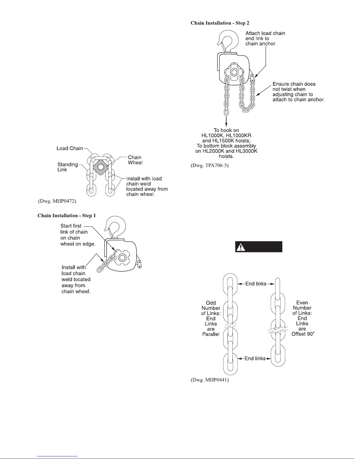
2. From the side of the chain wheel opposite the chain anchor
bolt, engage the first link of load chain in a pocket of the
chain wheel on edge. Refer to Dwg. TPA706-4, ‘Chain
Installation - Step 1.’ The weld on the load chain link must
face away from the powered chain wheel. Refer to Dwg.
MHP0472.
3. Rotate the brake driver by hand to feed the load chain
through the hoist.
5. Attach free end of load chain to hook. Inspect chain while
operating hoist slowly. Ensure chain feeds through chain
wheel smoothly, without sticking or binding. Repeat
operation in the opposite direction.
(Dwg. TPA706-4)
4. Keep the load chain straight and do not twist it. Attach the
free end of the load chain to the connecting link. Refer to
Dwg. TPA706-3, ‘Chain Installation - Step 2.’ Clean,
inspect and install the brake spring, brake discs, brake
plates and piston housing on hoist.
HL2000K and HL3000K
The following steps describe the initial installation of chain on
double fall hoists that do not have load chain installed.
1. Complete steps 1 through 4 of “HL1000K, HL1000KR and
HL1500K Chain Installation” section. Refer to MHP0472,
TPA706-4, and TPA706-3.
• Replacement chain for an HLK double fall hoist must have
an ODD number of total links. Refer to Dwg. MHP0441.
2. Ensure the chain is straight and feed the end through the
bottom hook chain wheel with the first link on edge with
the weld to the inside of the idler chain wheel. Refer to
Dwg. TPA706-2, ‘Chain Installation - Step 3.’
19
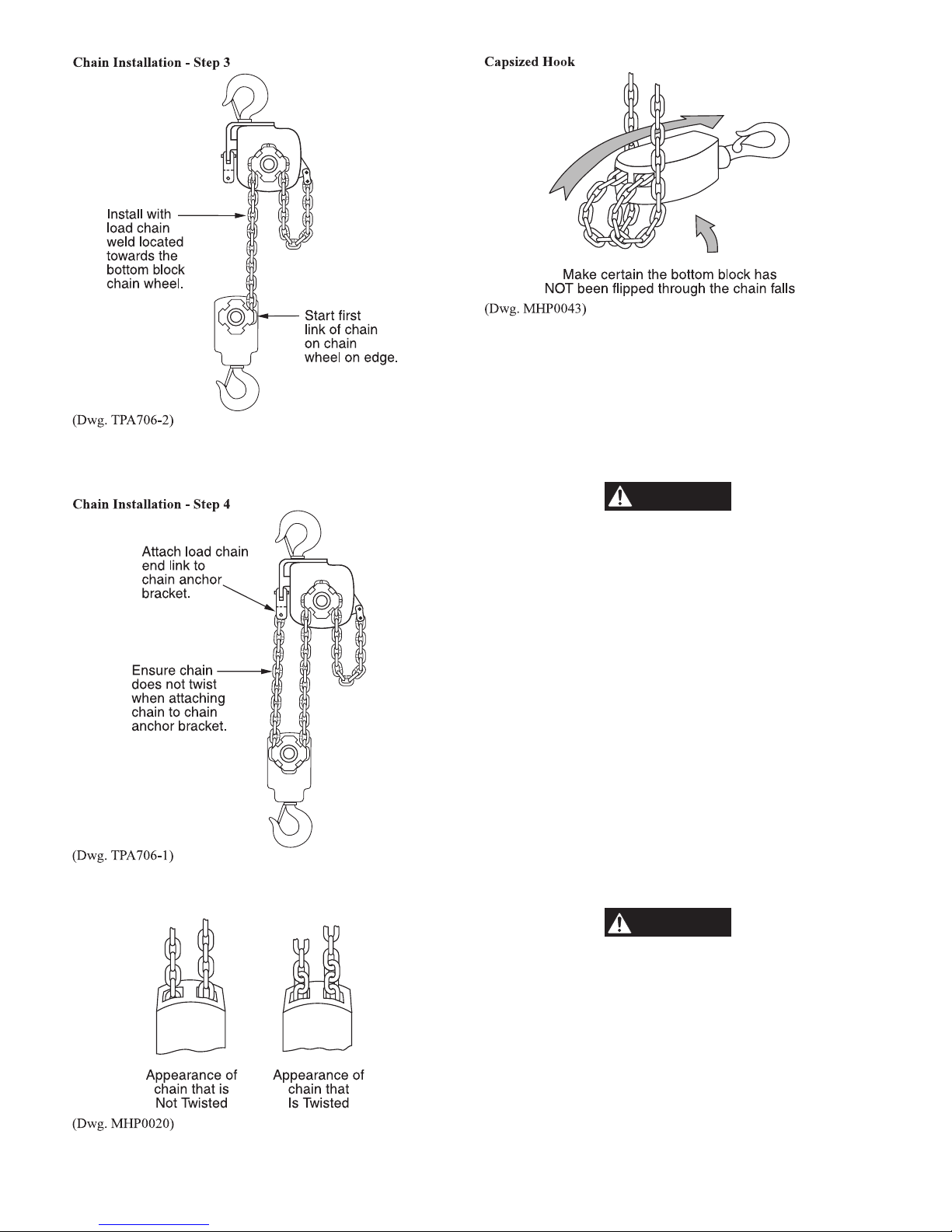
3. Ensure the chain is straight and attach the free end to the
CAUTION
WARNING
chain anchor bracket. Refer to Dwg. TPA706-1, ‘Chain
Installation - Step 4.’
HL4500K and HL6000K
The following steps describe the initial installation of chain on
three or four fall hoists that do not have load chain installed.
1. Remove the brake spring and piston housing, brake discs
and brake plates to expose the brake driver.
2. Place the edge of the first link of load chain in a pocket of
the hoist powered chain wheel. Refer to Dwg. MHP0472.
The weld on the load chain link must face away from the
powered chain wheel pocket.
• Improper installation of the load chain will cause
premature wear of the chain wheels resulting in damaged
equipment, which can cause injury or property damage.
3. Rotate the brake driver by hand to feed the load chain
through the hoist in the direction of the dead end chain
anchor (raise direction).
4. Keep the load chain straight, do not twist it. Attach the free
end of the load chain to the connecting link. Refer to Dwg.
TPA1056 for HL4500K and Dwg. TPA1057 for HL6000K.
Clean and inspect the brake parts and assemble.
5. On HL6000K hoists, slide the limit stop tube onto the load
chain.
6. Keeping the load chain straight, complete the load chain
installation as described in either the HL4500K or
HL6000K ‘Hoist Load Chain Reeving’ section.
4. Inspect to ensure chain is not twisted, kinked or “capsized”.
Refer to Dwg. MHP0020 and MHP0043.
HL4500K Hoist Load Chain Reeving
Refer to Dwg. TPA1056.
After the load chain has been correctly installed onto the hoist
powered chain wheel it must be carefully routed through the
lower block idler chain wheel, the upper suspension idler chain
wheel and secured to the bottom block housing as described in
this section.
• Twisted load chain can jam as it passes over the chain
wheel causing damage to the hoist or breaking the load chain
which can cause injury or property damage.
1. Raise the bottom hook block to a position near the hoist
where it can be properly supported and restrained from
movement.
2. Ensure the load chain remains straight. Feed load chain
through bottom block idler chain wheel.
20
 Loading...