

Page 1
GB
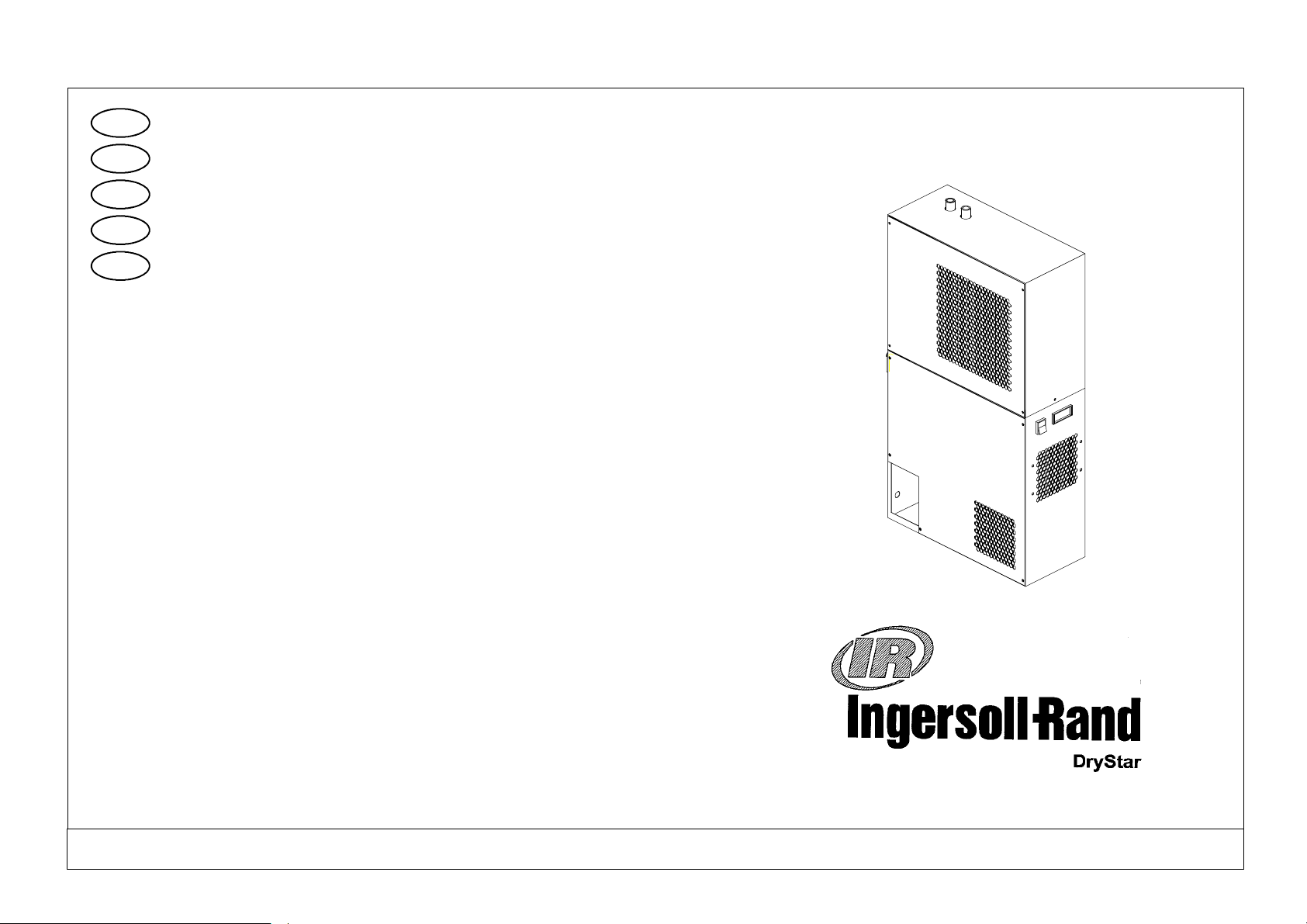
User manual
Page 1
F
ES
P
D
Manuel d’utilisation
Manual de uso
Manual do utilizador
Benutzerhandbuch
Page 7
Página 13
Página 19
Seite 25
DS15-- H --- D S 1 0 0 -- H
refrigeration dryer (60Hz)
DATE: 06.11.2002 ISSUE: 2
272716
CPN: 85616902
Page 2
Index
1Introduction page2
1.1 Foreword page 2
1.2 Packaging page 2
1.3 Transport page 2
1.4 Storage page 2
1.5 Inspection page 2
2 Installation page 2
2.1 Dryer installation page 2
2.2 Electrical connection page 3
2.3 Condensate drain page 3
3 Start--- up and operation page 3
3.1 Preliminary checks page 3
3.2 Starting the dryer page 3
3.3 Stopping the dryer page 4
3.4 Operation page 4
4 Maintenance page 4
4.1 Preventive maintenance page 4
4.2 Substituting an exhausted element page 4
4.3 Disassembling t he unit page 5
4.4 Refrigerant leaks in the refrigeration circuit page 5
4.5 Refrigerant charging page 5
5Calibration page5
Safety warnings
Important:
S Keep this manual with the machine throughout its entire service life.
S Carefully read this manual before carrying out any operation on the machine.
S This m achine is designed for PROFESSIONAL USE only. Only use the ma-
chine for the purpose for which it is intended. Improper use of the machine
absolves the manufacturer from all liability.
This manual has been compiled to help the final user perform just those operations which do not require removal of the panels.
All other operations which involve the removal of covers from instruments or
electrical circuit--- breakers using special tools must only be carried out by
trained personnel due to the danger of rotating parts or live components.
Each machine is equipped with an electric disconnect device whichallows theoperator to work on the machinein absolute safety. This device must always be used
to disconnect the mains supply to avoid any risk of danger during maintenance
work (electric shocks, scalding, automatic start--- up, moving parts and remote
control).
Before servicing the dryer always make sure the compressed air circuit is depressurised.
When requesting technical assistance or ordering spare parts, always quote the
model and serial number on the identification plate mounted externally on the
unit.
IMPORTANT: data contained in this publication is to be considered as indicative
only. The manufacturer reserves the right to modify data without prior notice.
6 Spare parts list page 5
7 Troubleshooting page 6
CPN: 85616902 --- DS15-- H --- D S 1 0 0 -- H
English
1
Page 3
CPN: 85616902 --- DS15-- H --- D S 1 0 0 -- H
English
2
2
All figures to which the “see Fig.” references in this text refer can be found at the
end this manual. The language translations for these figures can be found in the
Legend (A3--- sized page) inserted after all the figures.
1Introduction
1.1 Foreword
The DS- H dryers are designed to guarantee high quality compressed air and minimum maintenance.
Please carefully read this manual to obtain maximum performance from your dryer
and ensure its correct installation and start ---up in compliance with manufacturer instructions.
1.2 Packaging
The dryer is packaged with a strong cardboard box strapped to a wooden pallet.
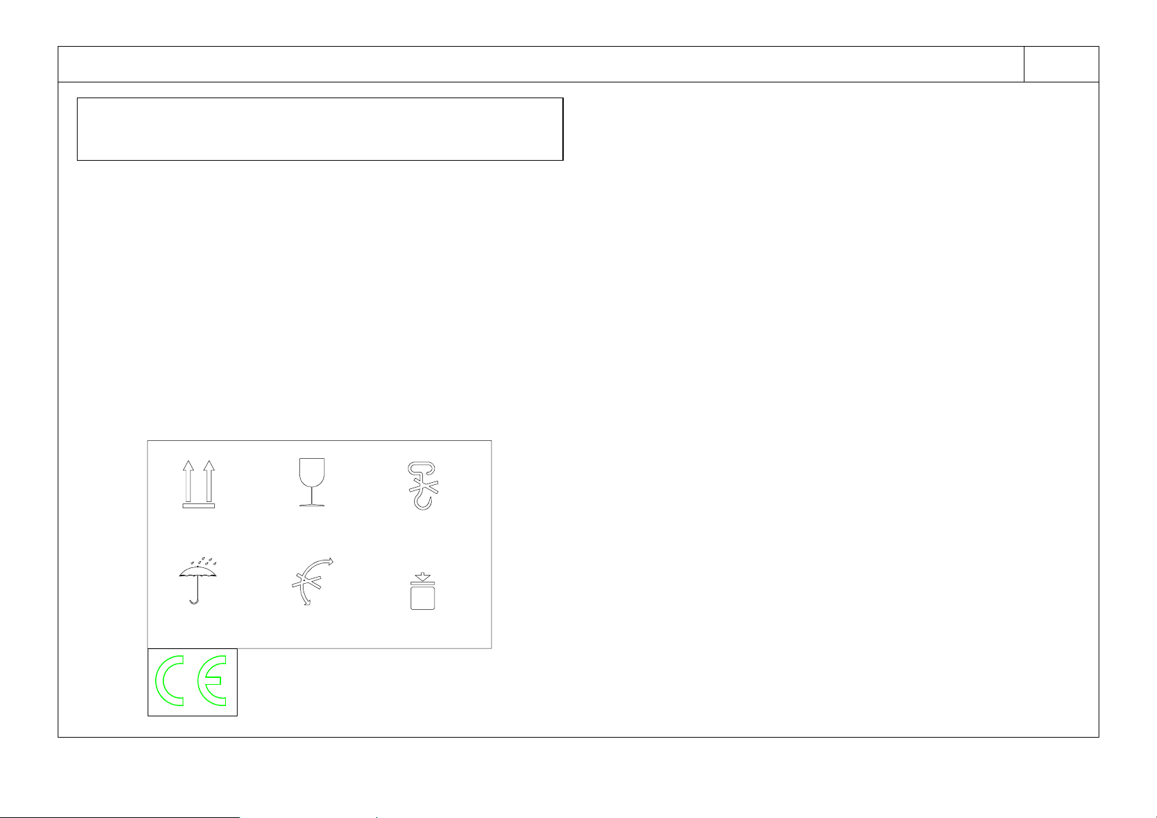
Instruction symbols (UNI ISO 780) for the movement, transport and stocking of the
product are printed on two sides of the packing.
1.3 Transport
S Keep the unit in an upright position and do not leave it outdoors.
S Use a forklift truck to move the machine.
S Care should be taken to avoid damaging internal components through poor
handling during movement, installation or use.
S Unpack the machine as close as possible to the installation site.
1.4 Storage
If stored the packaged units must be kept inside, protected from humidity, direct
sunlight and rain.
Moreover, although stacking is permitted the maximum weight must not be more
than the value shown on the packaging.
1.5 Inspection
On receipt of the machine, make sure it has incurred no damage during transit.
If any damage is detected promptly contact the haulage company.
2 Installation
2.1 Dryer installation (see Fig. 1)
THIS WAY UP
KEEP DRY DO NOT ROLL STACKING
FRAGILE: HANDLE
WITH C ARE
USE NO HOOKS
Kg max
LIMITATION
a) Dryer should be installed indoors; where this is not possible it must however be
installed in a clean dry area, with a temperature within the limits 41---115˚F
( 5 --- 4 6 ˚C), and sheltered from the effects of direct weather (including direct sun-
light); do not install the dryer in rooms used for laundry operations.
b) The compressed air inlet temperature must never exceed 200˚F(93˚C). For dif-
ferent temperatures to those indicated above, consult the manufacturer.
c) For most compressed air applications we recommend following the installation
plan (see Fig. 1). This layout ensures optimum compressor, filter and dryer performance and also guarantees excellent air qua lity whilst minimising operating
costs.
d) Donotobstructthedryerairgrilles.
e) Allow sufficient gap around the unit to facilitate maintenance and ensure unim-
peded air discharge from the condenser.
Page 4
f) Avoid recirculation of hot condenser air back into t he condenser air inlet.
.
g) If the system is prone to instantaneous pressure surges which exceed the dryer’s
rated capacity, mount a suitably sized receiver near the overpressure source. For
more precise information, contact the manufacturer or distributor.
h) Installing a by--- pass line with shut---off valves (supplied as option) is suggested
to permit maintenance or calibration without interrupting the compressed air
flow to the user.
Pay attention when you by--- pass the aftercooler section, as this will cause hot air
to flow through the compressed air network.
i) Correctly connect the dryer to the air inlet and outlet connections. If the com-
pressed air network is prone to vibrations, use hoses to make the connections.
If the mains is subject to high levels of pulsation, ensure that the connection is
equipped with pulsation dampers.
j) Do not connect condensate drains common to other pressurised drain lines in a
closed circuit. Make sure the outflow from the condensate drains is unimpeded.
Connect the condensate piping in such a way to ensure that sound levels are kept
to a minimum during drainage.
Ensure that all condensate is disposed of in a responsible manner, in accordance
with local norms concerning environmental protection.
k) The ambient air around the dryer and compressor must not contain solid or gas-
eous contaminants. All compressed and condensed gases can generate acids or
chemical products which may damage the compressor or components inside the
dryer.
Take particular care with sulphur, ammonia, chlorine and installations in marine
environments. For further advice or assistance consult the manufacturer.
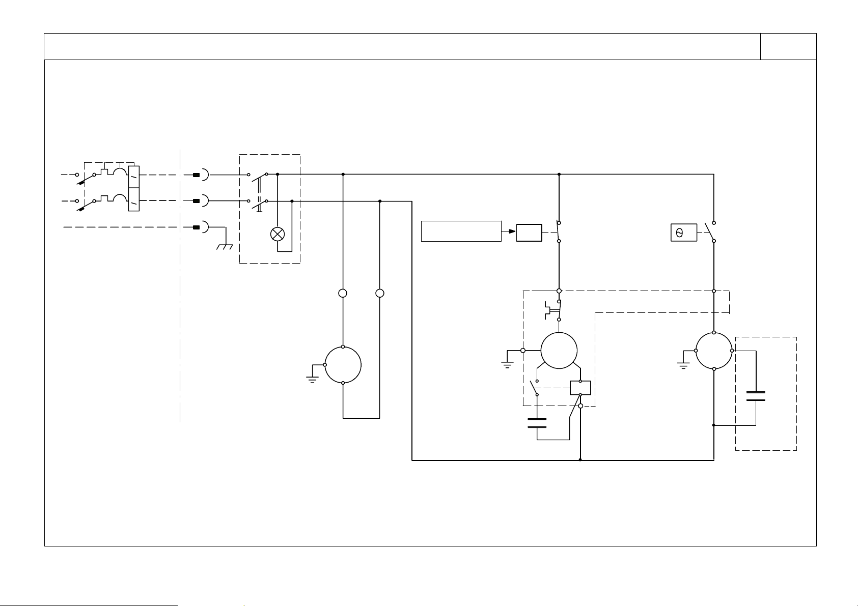
2.2 Electrical connection (see Fig. 5 / Fig. 10)
The dryer is supplied with a 3 x AWG16 power cable complete with plug.
2.3 Condensate drain
The dryer is supplied either with a float drain (see Fig. 9), a timed drain or an electronic level sensing drain.
Fortimed and electronic drains:refer to separate manual supplied with the dryer for
specific details concerning the condensate drain.
3 Start---up and operation
3.1 Preliminary checks
Beforestartingupthedryer,makesurethat:
a) the air inlet valves are closed and there is no air flow through the dryer.
b) The mains power supply is commensurate with the dryer voltage.
c) The dryer is installed in compliance with the installation instructions given in
Chapter 2.
3.2 Starting the dryer
a) Use the switch to start the dryer.
b) Always start up the dryer before activating the air compressor.
c) Waitabout 5 minutes until the dryer is running at the correct operatingtempera-
tures and pressures.
d) Slowly open the air inlet valve to pressurise the dryer.
e) Slowly open the air outlet valve. The dryer is now operating (drying).
f) Always leave the dryer running while the air compressor is operating.
g)
After stopping the dryer wait at least 3 minutes before starting it again
Install an overcurrent and earth leakage circuit breaker upstream from the
plant (IDn = 0.03A) with a 0.12 inch (3 mm) gap between contacts when open (refer
also to local laws).
CPN: 85616902 --- DS15-- H --- D S 1 0 0 -- H
3.3 Stopping the dryer
a) Use the switch to stop the dryer.
English
3
Page 5
CPN: 85616902 --- DS15-- H --- D S 1 0 0 -- H
y
WEEKL
Y
CONDENATEDRAI
N
MONTHLY
Mak
t
h
d
t
200F(93C)
EVERY4MONTH
S
specification
s
English
4
4
b) Stop the dryer 2 minutes after shutting down the air compressor or interrupting
the air flow to the dryer.
Avoidallowingcompressedairtoenterthedr
er when the dryer is
switchedofforwhenitisinanalarmsituationwhichstopstherefrigeration
compressor.
3.4 Operation
S The dryer operates automatically. It is factory set for a dew point of 50˚F(10˚C)
and therefore requires no further calibration.
S Do not exceed the machine’s design limits, by---pass excess air flow and check the
unit model and/or installation.
S For maximum performance from your dryer, follow the maintenance schedule de-
scribed i n Chapter 4.
S The sound pressure level recorded for these dryers 40 inch (at 1 metre) from the
machine in free fieldconditionsis less then50 dB(A) (models DS15-- H), 55dB(A)
(models DS25-- H --- D S 1 0 0 -- H)
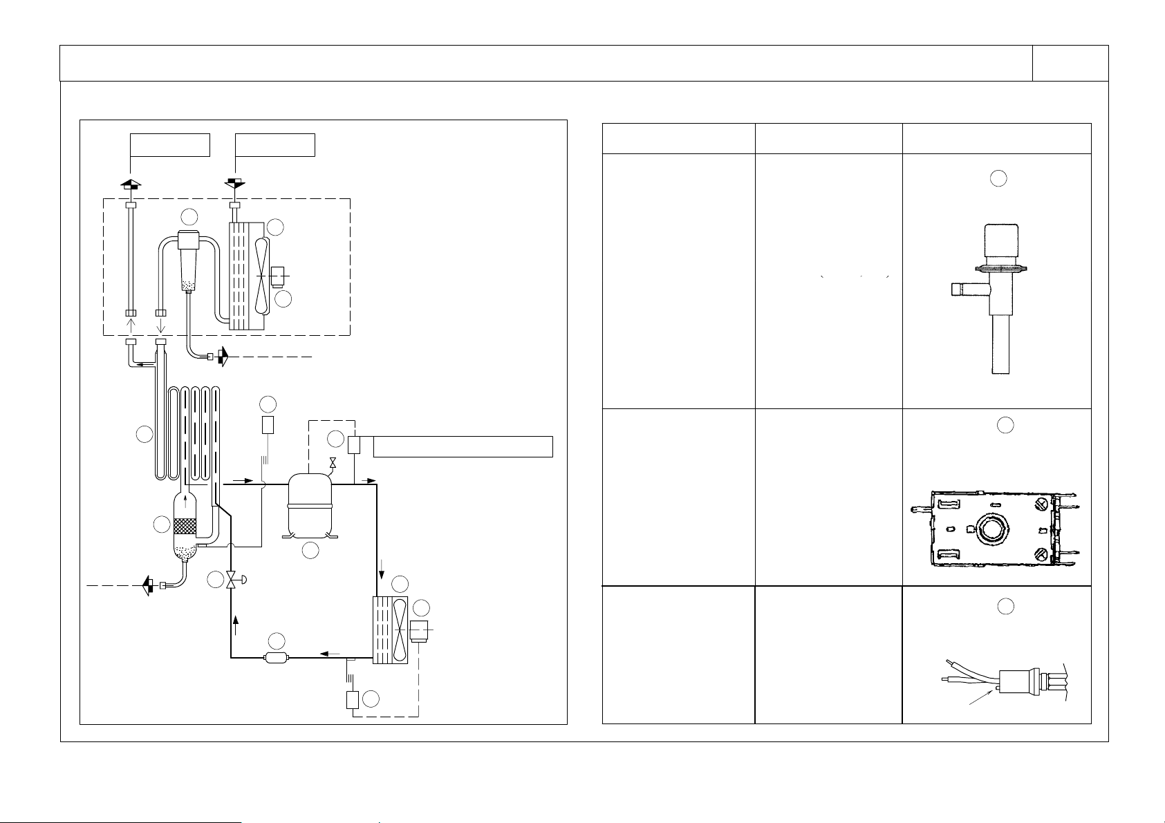
Fig. 6 shows the Dryer’s refrigeration and air circuits.
N.B.: In the event of aftercooler fan malfunction leading to an increase in the tem-
perature within the filter, to above 149˚F(65˚C), check the integrity of the filter’s
element and drain and substitute these components if necessary.
4 Maintenance
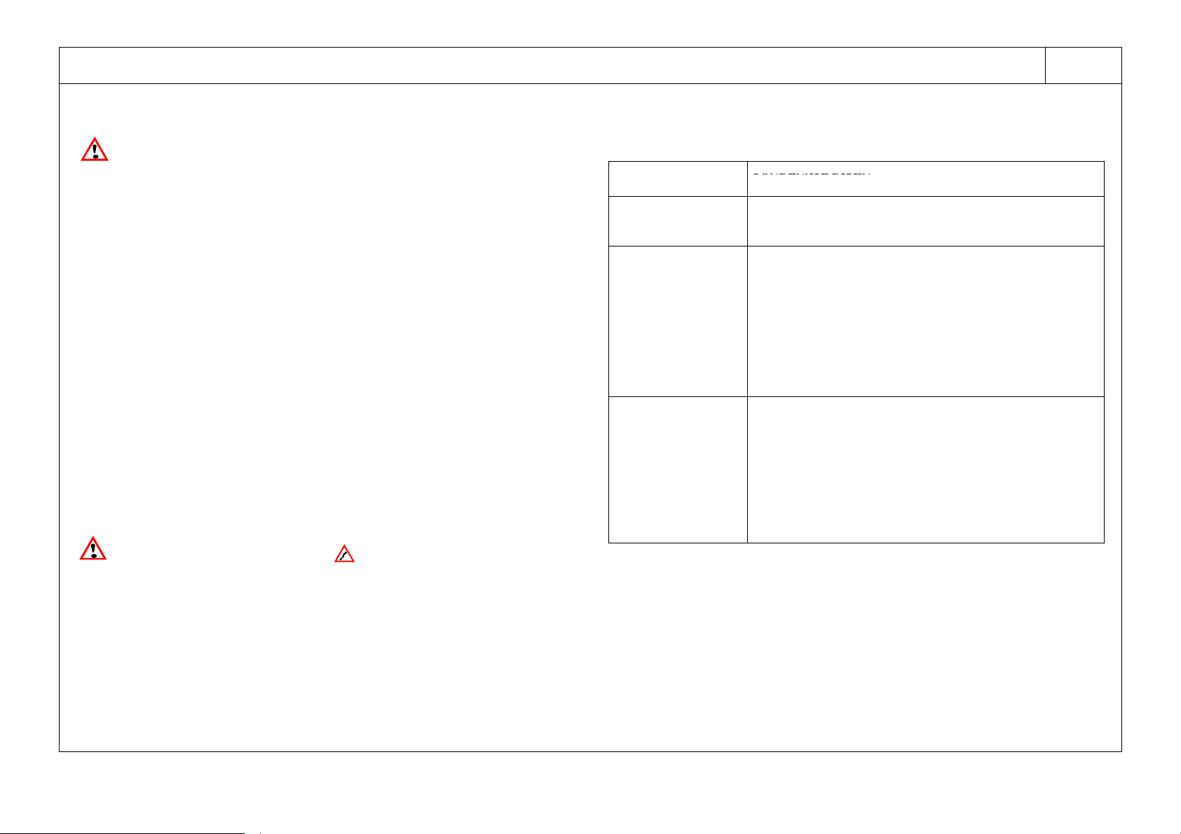
4.1 Preventive maintenance
For optimum performance from your dryer follow the periodic maintenance schedule described below.
CONDENATE DRAIN
Verify that the condensate drain is draining correctly.
COMPRESSOR
˚
˚
YEARLY
esure
when running. If this is not the case consult Chapter 7.
REFRIGERANT CONDENSER AND AFTERCOOLER
Remove any dust from the condenser/aftercooler fins.
COMPRESSOR
Make sure compressor power consumptioncomplieswith data plate
AFTERCOOLER FAN MOTOR
S
Check that the fan rotates freely without any abnormal noise.
S
Make sure fan power consumption complies with the specifications on the fan’s data plate.
AFTERCOOLER
If necessary (coil blocked) remove the fan and clean the coil in the
opposite direction to the air flow using a high pressure water jet (this
operation must be performed by a technician to avoid damage).
FILTER ELEMENT
Replace the filter element (see para. 4.2)
CONDENSATE DRAIN
Completely disassemble the drain and clean all its components (see
Fig. 9 or separate manual, according to installed drain type).
e compressorhea
.
emperatureisbelow
Before accessing live electrical parts , disconnect the power supply to the
dryer using disconnect switch QS or disconnect the cable connections.
SAFETY DEVICES
SK overload protector
HP high pressure switch (installed on models DS50-- H --- D S 1 0 0 -- H)
COMPRESSOR TYPE
HERMETIC, PISTON (single phase)
N.B.: Always use original spares supplied by the manufacturer.
Failure to do so renders the manufacturer not liable for incorrect unit operation.
4.2 Substituting an exhausted element (Fig. 9)
N.B.: Don’t touch the element sock with your bare hands; use gloves.
a) Shut off or by---pass air supply to dryer.
b) Depressurise filter usingmanual or automatic drainvalve (18). Leave valveopen.
c) Unscrew (anticlockwise) filter body from head.
d) Unscrew and remove element (17).
e) Clean inside of filter if necessary.
Page 6
f) Insert new element (17) together with new O---ring. Tighten element.
g) Tightly screw (clockwise) filter body onto head.
h) Verify that all components are properly tightened.
i) Slowly open air inlet shut ---off valve upstream of dryer.
j) Allow air to flow for a few minutes and then close drain valve (18).
k) Open air outlet shut--- off valve downstream of dryer.
4.3 Disassembling the unit
The machine has been designed andconstructedto guarantee continuous operation.
The long service life of some components such as the fan and compressor depends
on good maintenance.
Theunitmustonlybedisassembledbyarefrigerantspecialist.
Refrigerant liquid and lubricating oil inside the refrigeration circuit must be recovered in compliancewith current norms in the country where the machine is installed.
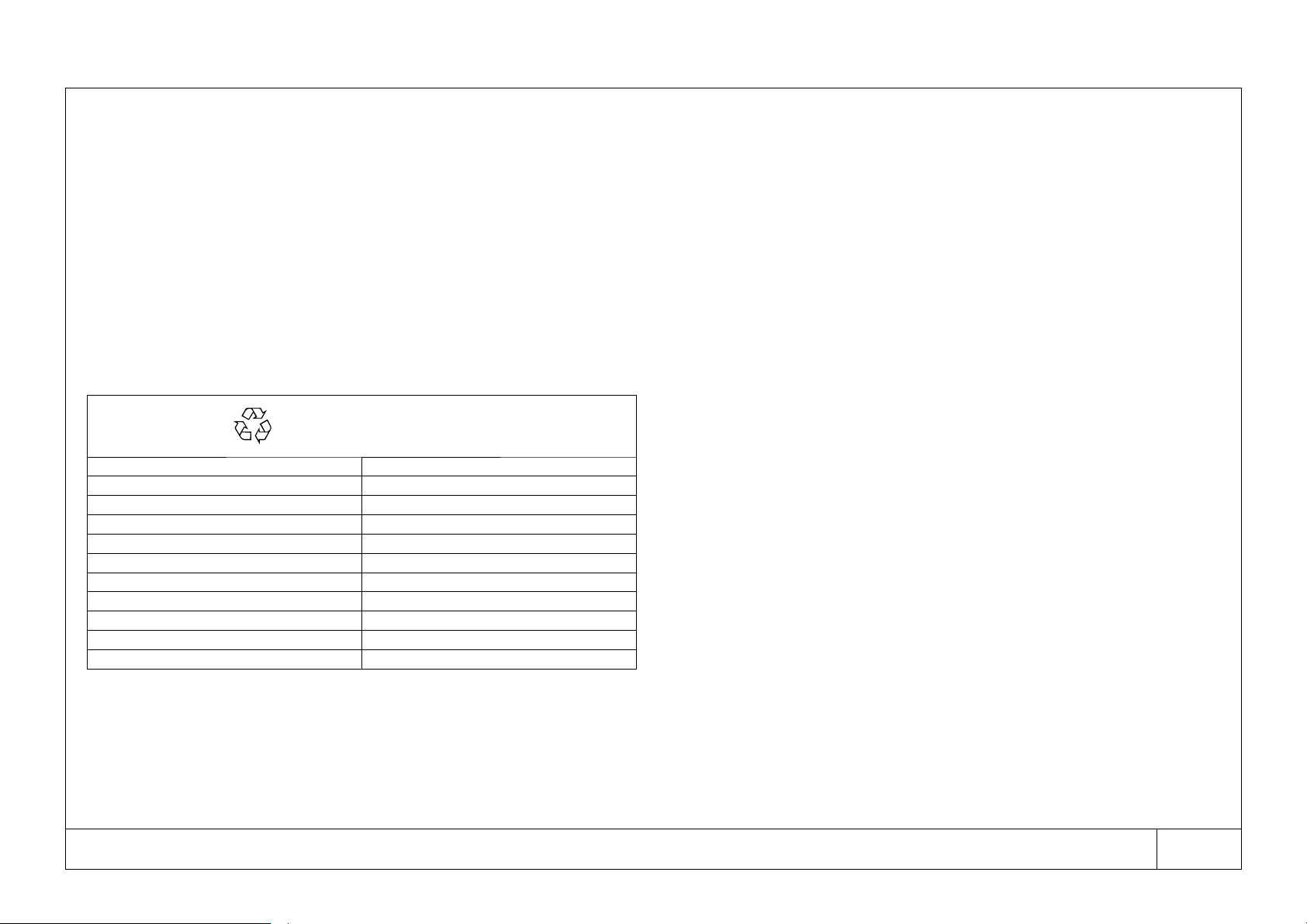
RECYCLING
DISASSEMBLY
frame and panels steel/epoxy resin polyester
heat exchanger (cooler) copper
pipes copper
drainage system polyamide
heat exchanger insulation EPS (polystyrene sintered)
pipe insulation gum synthetic
compressor steel/copper/aluminium/oil
condensator steel/copper/aluminium
refrigerant R134a
valve brass
electrical cable copper/PVC
4.4 Refrigerant leaks in the refrigeration circuit
FOREWORD
The unit i s delivered in perfect working order, already charged as specified in Fig. 5.
Refrigerantleaks maybe identified by tripping of the compressor overloadprotector
(SK).
IF A LEAK IS DETECTED IN THE REFRIGERANT CIR CUIT SEEK TECHNICAL ASSISTANCE.
4.5 Refrigerant charging (see Fig. 5)
THIS OPERATION MUST ONLY BE PERFORMED BY A REFRIGERANT
SPECIALIST.
WHEN REPAIRING THE REFRIGERANT CIRCUIT, COLLECT ALL THE REFRIGERANT IN A CONTAINER AND DISPOSE OF IT IN THE APPROPRIATE
MANNER.
Characteristics of refrigerant R134a
In normaltemperature and pressure conditions the above refrigerant is a colourless,
class A1/A1 gas with TVL value of 1000 ppm (ASHRAE classification).
If a refrigerant leak occurs thoroughly air the room before commencing work.
5Calibration
The dryer is supplied factory set with the values shown in Fig. 7 and therefore requires no further calibration.
6 Spare parts list
This list contains the principal spare parts. When ordering spare parts always quote
the quantity, part CPN and machine serial number.
(see. Fig. 8)
CPN: 85616902 --- DS15-- H --- D S 1 0 0 -- H
English
5
Page 7
CPN: 85616902 --- DS15-- H --- D S 1 0 0 -- H
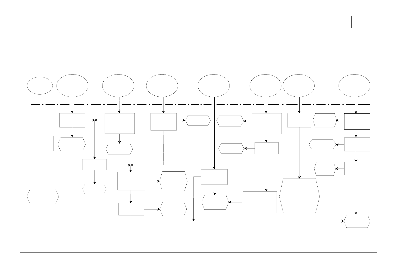
7 Trouble shooting
The following diagram lists the various problems which may occur during thedryer’s
service life. In the case of serious diffi culties however, contact a refrigerant specialist.
NOTE: Always by---pass the dryer when it is out of service.
English
6
6
FAU LT
CAUSE
and
REMEDY
high dew
point
Compressed
air pressure
too low
Yes
Increase air
pressure
No
Fan does
not work
Yes
Repair
fan
High air
temperature
Condenser dirty
No
air outlet
condenser
No
outlet
(cooling
too hot)
Yes
Clean
thermal load
(compressor
head too hot)
Low current
consumption
Excessive
No
No
Overload
protector SK
tripped
Ambient
temperature
over 115˚F
(46˚C)
No
Yes
Yes
Yes
Reduce
compressed air
quantity or
air
temperature
Lack of
refrigerant:
Recharge
Reduce
temperature
No
Compressor
noisy
Compressor
components
perished
Yes
Repair or
replace com-
pressor
Clean
condenser
Repair
fan
Yes
Yes
Compressor
winding insulation
partially perished
Yes
(compressor
Excessive
current
consumption
Condenser dirty
(cooling
air outlet
too hot)
No
Fan does
not work
No
too hot)
No
Ice
formation
Low
evaporation
pressure
Yes
b y --- p a s s a i r b y k e e p -
ing air inlet open.
Manually open con-
densate drain. Re-
pair before restarting
(check automatic
expansion valve
setting)
Calibrate or
replace
thermostat
Clean
condenser
Replace
fan
High refriger-
ant discharge
pressure
Fan ther mos tat
switch (TV)
incorrectly
Yes
calibrated
No
Condenser
Yes
No
Fan does
not work
Yes
No
Seek exter-
nal assis-
dirty
tance
Page 8
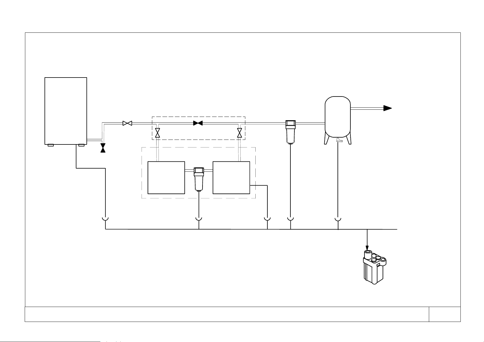
Fig. 1 Installation
compressor
receiver
b y --- p a s s
(suggested)
high inlet temperature dryer package
filter
Aftercooler
to compressed air ring main
filter
Dryer
CPN: 85616902 --- DS15-- H --- D S 1 0 0 -- H
oil/water separator
31
Page 9
CPN: 85616902 --- DS15-- H --- D S 1 0 0 -- H
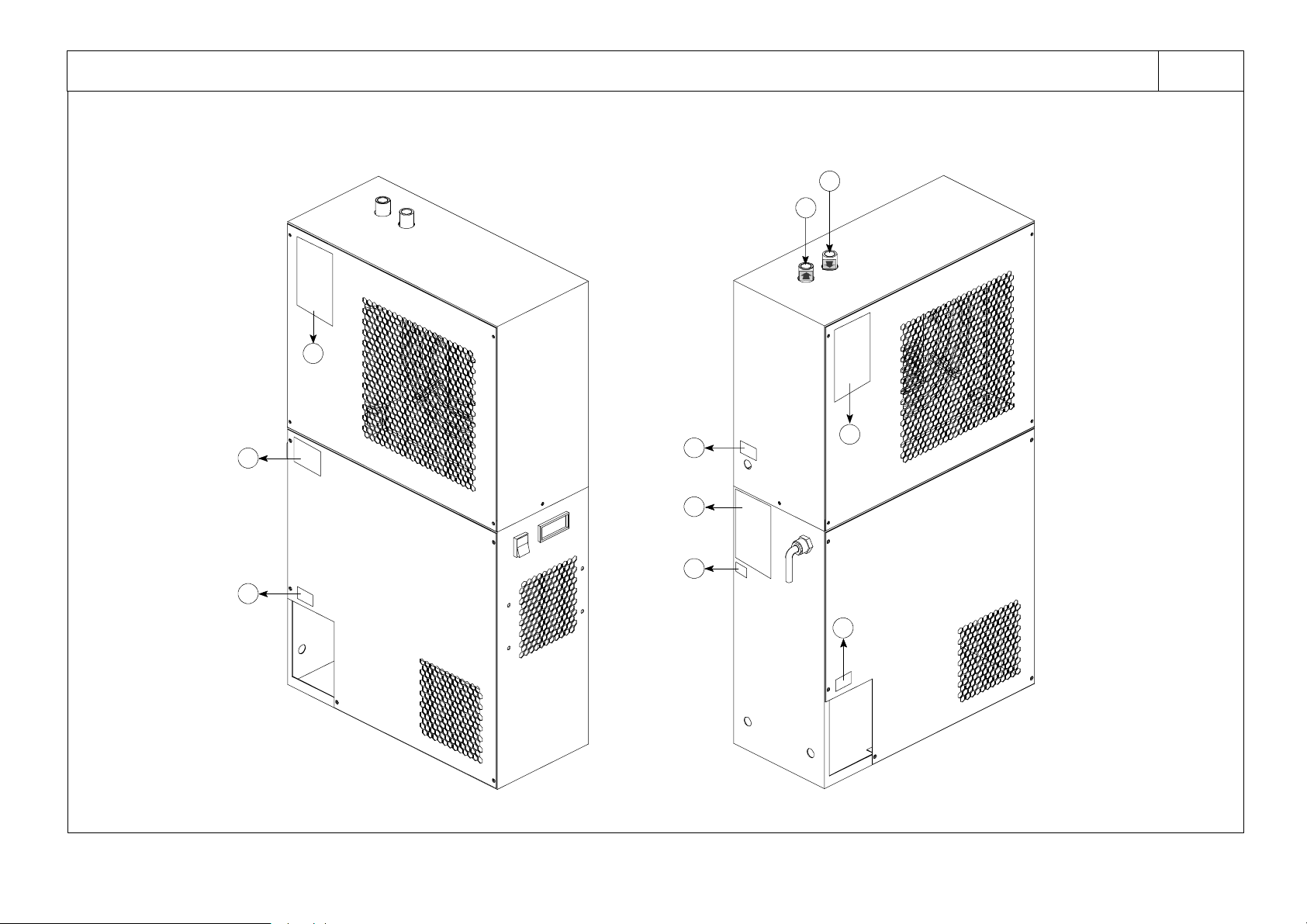
Fig. 2 Safety and description lab els on dryer
b
32
d
e
g
f
f
a
c
b
f
Page 10
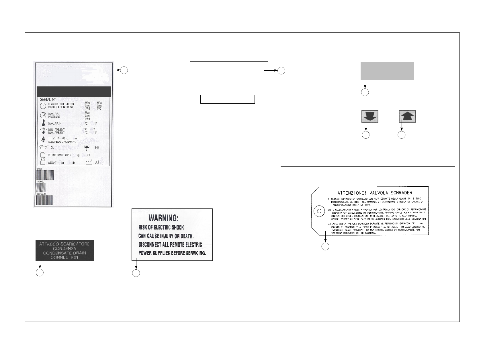
Fig. 3 Safety and description lab els on dryer
DS25-- H
a
S Model
S Serial No.
S Low/High side refrigeration
circuit design pressure
S Max air pressure
S Max air inlet
S Min. ambient
Max ambient
S Power supply
Electrical diagram no.
S Oil
S Refrigerant
S Weig ht
REMEMBER
TO CHANGE YOUR
FILTER ELEMENT
element installed on:
We strongly recommend filter
elements be changed once a
year or after 8000 working
hours, whichever comes first.
Only use genuine Ingersoll
Rand elements.
RefertoUserManualfor
correct replacement element.
b
REMEMBER
TO CHANGE YOUR
FILTER ELEMENT
element installed on:
We strongly recommend filter
elements be changed once a year
or after 8000 working hours,
whichever comes first.
Only use genuine Ingersoll
Rand elements.
RefertoUserManualforcorrect
replacement element.
QUALITY
CHECKED
INSPECTOR N. 302
QUALITY CHECKED
c
INSPECTOR N. 302
d e
Air inlet Air outlet
Internal dryer
Condensate drain
f
connection
CPN: 85616902 --- DS15-- H --- D S 1 0 0 -- H
WARNING:
g
Risk of electric shock
can cause injury or death.
Disconnect all remote electric
power supplies before servicing.
h
1 This unit is equipped with refrigerant as for quantity andkind clearly shown
in operating manual and with identification label.
2 Any ordinary test and / orrefrigerant recharge by means of connections can
take place only after refrigerant evacuation. The evacuation must be proportional to dimensions and length of the connections used. The use of the
valve can be justified only when the dryer is not in working order.
3 During the unit guarantee period, the Schrader valve canbe used by autho-
rized staff only, otherwise any damage caused by a wrong refrigerant
recharge will not be under warranty.
ATT ENTIO N: SCHRADER VALVE
33
Page 11
CPN: 85616902 --- DS15-- H --- D S 1 0 0 -- H
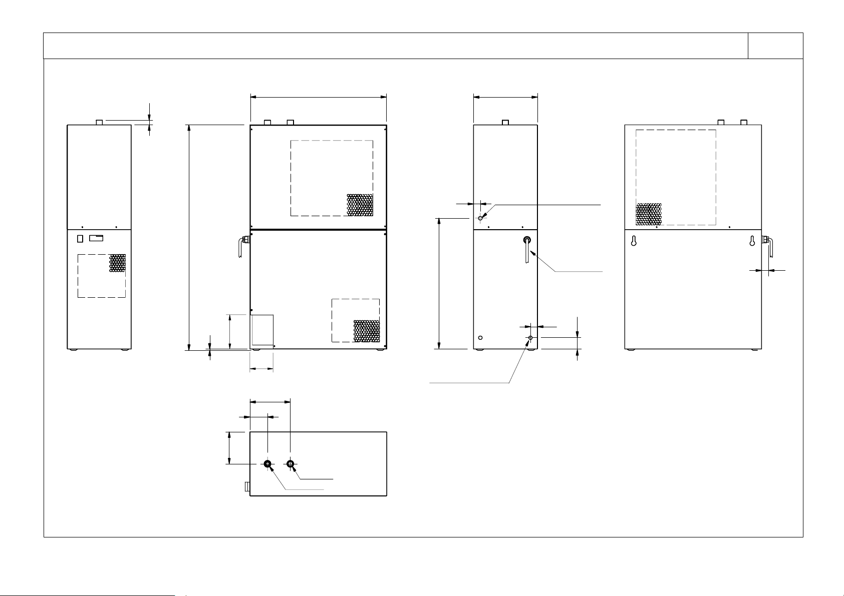
Fig. 4 Overall dimensions
34
A
H
L
B
D
J
I
K
condensate drain tube
C
filter / separator
discharge tube
supply cable
M
N
O
G
F
E
air inlet
air outlet
Page 12
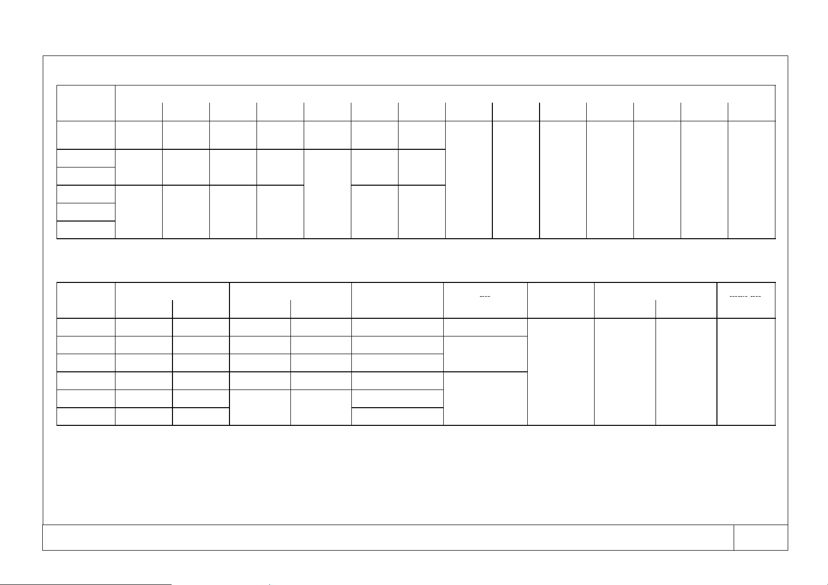
Fig. 4 Overall dimensions
l
2
3.6
3
9.0
1
1.1
2
2.6
3.0
7.0
(
)
(22)(5)(152)(102)(30)(50)(22)
(
)
(
)
(
)
(
)
(140)
(
)
(
)
(700)(1212)(352)(650)(8
3.5)(18
3.5
)
l
air
maxai
r
1/2”NPT--F
32011.2
9
mode
DS15-- H
DS25-- H
DS35-- H
DS50-- H
DS75-- H
DS100-- H
Fig. 5 Technical data
mode
DS15-- H 25 55 130 4.59 3.7 3/8” NPT-- F
DS25-- H 42 93 195 6.88 5.6
DS35-- H 43 95 200 7.05 7.0
DS50-- H 61 134 240 8. 46 8.8
A B C D E F G H I J K L/M N O
17.7
(450)
23.6 39.0 11.1 22.6 3.0 7.0
(600)
27.6
700
(kg) (lb) (gr) (oz) 115V 1~ 60Hz
32.1
(815)
(990)
47.7
1212
weight refrigerant / charge R134a F. L . A . [ A ]
7.6
(197)
(282)
13.9
352
19.7
(500)
(575)
25.6
650
2.9
(73)
5.5
140
dimensions --- inches (mm)
3.2
(82)
(77)
3.3
83.5
5.2
(133)
(177)
7.2
183.5
0.9
air
connections
”
0.2
6.0
max. air ambient temperature
inlet temp. min. max.
200˚F 41˚F 115˚F 232 PSI
93˚C 5˚C 46˚C 16 bar
4.0
1.2
2.0
0.9
max air
pressure
DS75-- H 70 154
DS100-- H 73 161
CPN: 85616902 --- DS15-- H --- D S 1 0 0 -- H
11.0
13.6
3/4” NPT -- F
35
Page 13
CPN: 85616902 --- DS15-- H --- D S 1 0 0 -- H
DS1
5--H
DS100--H
(,)
36
Fig. 6 Refrigerant diagram
AIR OUTLET AIR INLET
17
condensate drain
10
5
11
16
15
Fig. 7 Calibration
13
1. compressor
2. refrigerant condenser
3. fan motor
4. evaporator
5. separator
7. expansion automatic valve
8. refrigerant filter
10. air --- air heat exchanger
11. dew point thermometer
12. fan condensing
temperature switch
13. high pressure switch
15. aftercooler fan motor
16. aftercooler coil
17. filter separator
only for model DS50-- H --- D S 1 0 0 -- H
MODEL SETTING
---
31.9 PSI (+0.15, --- 0)
(2.2 bar) (+0.1, --- 0)
START: 113˚F
COMPONENT
7
Automatic expansion valve
INLET
OUTLET
12
Fan co nden sing
temperature switch (TV)
(45˚C)
DS15-- H --- D S 1 0 0 -- H
(STOP: 104˚F)
(40˚C)
1
condensate
drain
7
8
2
3
DS50-- H --- D S 1 0 0 -- H
STOP: 406 PSI
(28 bar)
(START: 319 PSI
High pressure switch (HP)
13
(22 bar)
12
reset
Page 14
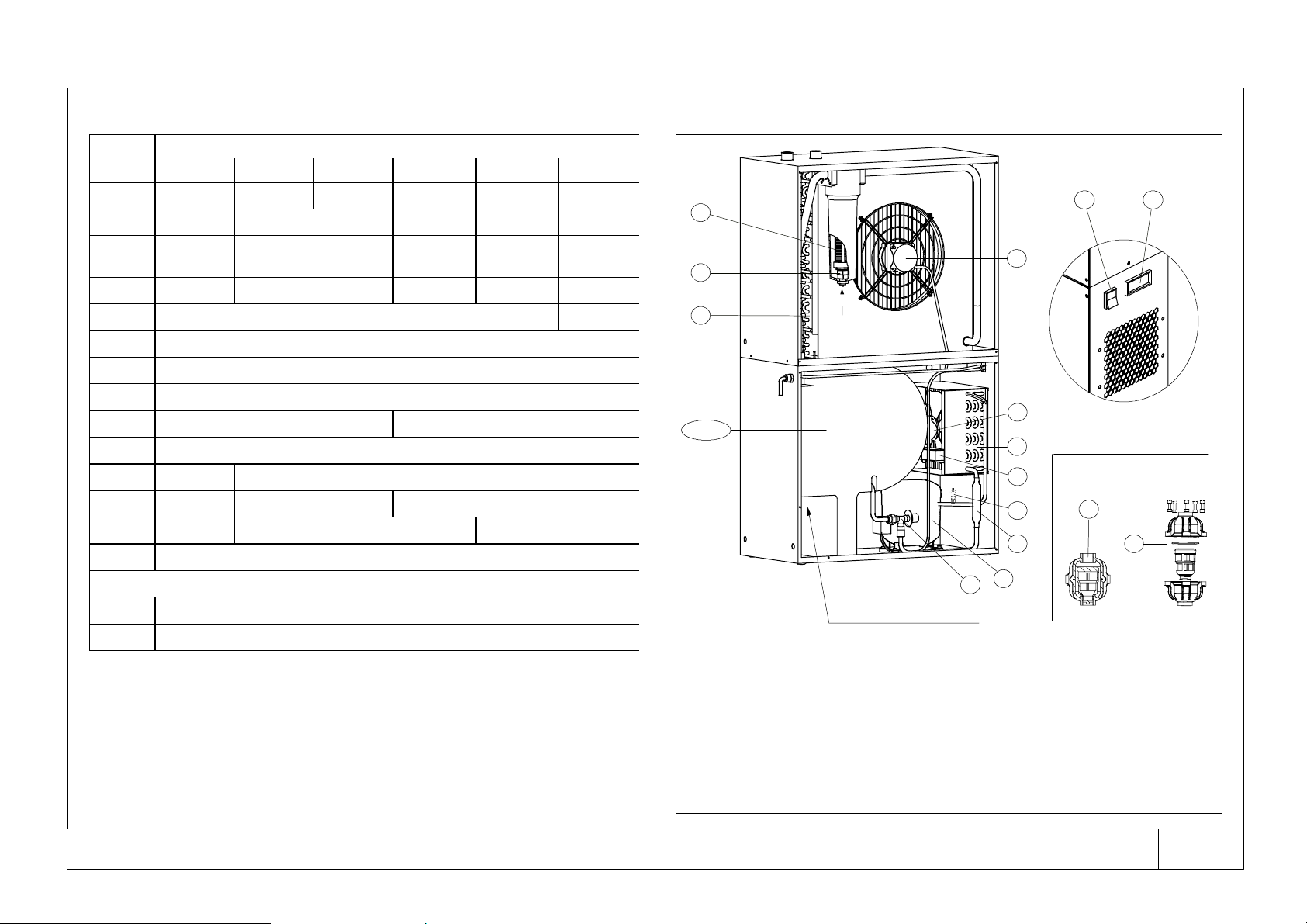
Fig. 8 Spare Parts L ist (see Fig. 9)
Fig. 9 Parts
Part
1. 89328223 89328231 89328249 89328256 89327704 85611879
2. 89327712 89327720 89327738 89327746 89320691
3. 89327811 89327829+89327761
4. 5. 10. 85613016 85613024 85613032 85613040 85613057
7. 89327902 89321038
8. 89327910
11. 89236145
12. 89327928
13. --- 38333209
14. 38333217
15. 85616829 85616837
16. 85616845 85616852 85616860
17. 85616878 85616886 85616894
18. 89327944
CONDENSATE DRAIN
A. 89327936
B. 89327951
DS15-- H DS25-- H DS35-- H DS50-- H DS75-- H DS100-- H
Codes
89327837+
89327787
89327837+
89327803
85611887
17
18
16
condensate
drain
connection
4.5.10
condensate drain connection
1. compressor
2. refrigerant condenser
3. fan motor
4.5.10. evaporator/separator/air --- air
heat exchanger
7. expansion automatic valve
8. refrigerant filter
11. dew point thermometer
12. fan condensing temperature switch
14 11
15
3
2
12
13
Float condensate drain
A
8
1
7
13. high pressure switch
14. main switch with on lamp
15. aftercooler fan motor
16. aftercooler coil
17. filter separator
18. drain valve
A. condensate drain (complete)
B . O --- r i n g
B
CPN: 85616902 --- DS15-- H --- D S 1 0 0 -- H
37
Page 15
CPN: 85616902 --- DS15-- H --- D S 1 0 0 -- H
Fig. 10 Electrical diagram
38
115V 1~ 60Hz
dd
GND
QF
Inn=0.03A
RECOMMENDED
and generally demanded
by law (by installer)
L1
L2
QS
L1
L2
GND
HL
LIMIT OF EQUIPMENT
R1
S1
R1 S1
EV2
only for model
DS50-- H --- D S 1 0 0 -- H
GND
HP
p
SK
R1
>
R3
1
1
3
C
MC
R
S
S
1
R
KA
2
N
R1
TV
>
R2
L
blue
EV1
brown
black
C2
C1
only for model
DS100-- H
S1
S1
Page 16

English -- Legend
LABELS
a S Model
S Serial No.
S Low/High side refrigeration
circuit design pressure
S Max air pressure
S Max air inlet
S Min. ambient
Max ambient
S Power supply
Electrical diagram no.
S Oil
S Refrigerant
S Weight
b. REMEMBER
TO CHANGE YOUR FILTER ELEMENT
element installed on:
We strongly recommend filter elements be changed once a year
or after 8000 working hours, whichever comes first.
Only use genuine Ingersoll Rand elements.
Refer to User Manual for correct replacement element.
c QUALITY CHECKED INSPECTOR N. 302
d. Air inlet
e. Air outlet
f. Condensate drain connection
g. WARNING:
Risk of electric shock can cause injury or death.
Disconnect all remote electric power supplies before servicing.
Internal Dryer
h. ATTENTION: SCHRADER VALVE
1 This unit is equipped with refrigerant as for quantity and kind clearly shown in operating
manual and with identification label.
2 Any ordinary test and / or refrigerant recharge by means of connections can take place
only after refrigerantevacuation.The evacuation must beproportional to dimensions and
length of the connections used. The use of the valve can be justified only when the dryer
is not in working order.
3 During the unitguarantee period, theSchrader valve can beused by authorizedstaff only,
otherwiseany damagecausedby awrong refrigerant rechargewillnotbeunderwarranty.
DRAWINGS
1. MC compressor
2. refrigerant condenser
3. EV1 fan motor
4. evaporator
5. separator
7. expansion automatic valve
8. refrigerant filter
10. air---air heat exchanger
11. dew point thermometer
12. TV fan condensing temperature switch
13 HP high pressure switch
14. QS--- HL main switch with on lamp (green)
15. EV2 aftercooler fan motor
16. aftercooler coil
17. filter separator
18 drain valve
SK overload protector
KA starting relay
C1 compressor starting capacitor
C2 fan motor run capacitor
QF residual current circuit---breaker (by installer)
A. condensate drain (complete)
B . O --- r in g
CPN: 85616902 --- DS15-- H --- D S 1 0 0 -- H
39
 Loading...