

Page 1
A
PPROVED 11/Jun/2020 11:47:53 GM
T
DA Heatless Purge
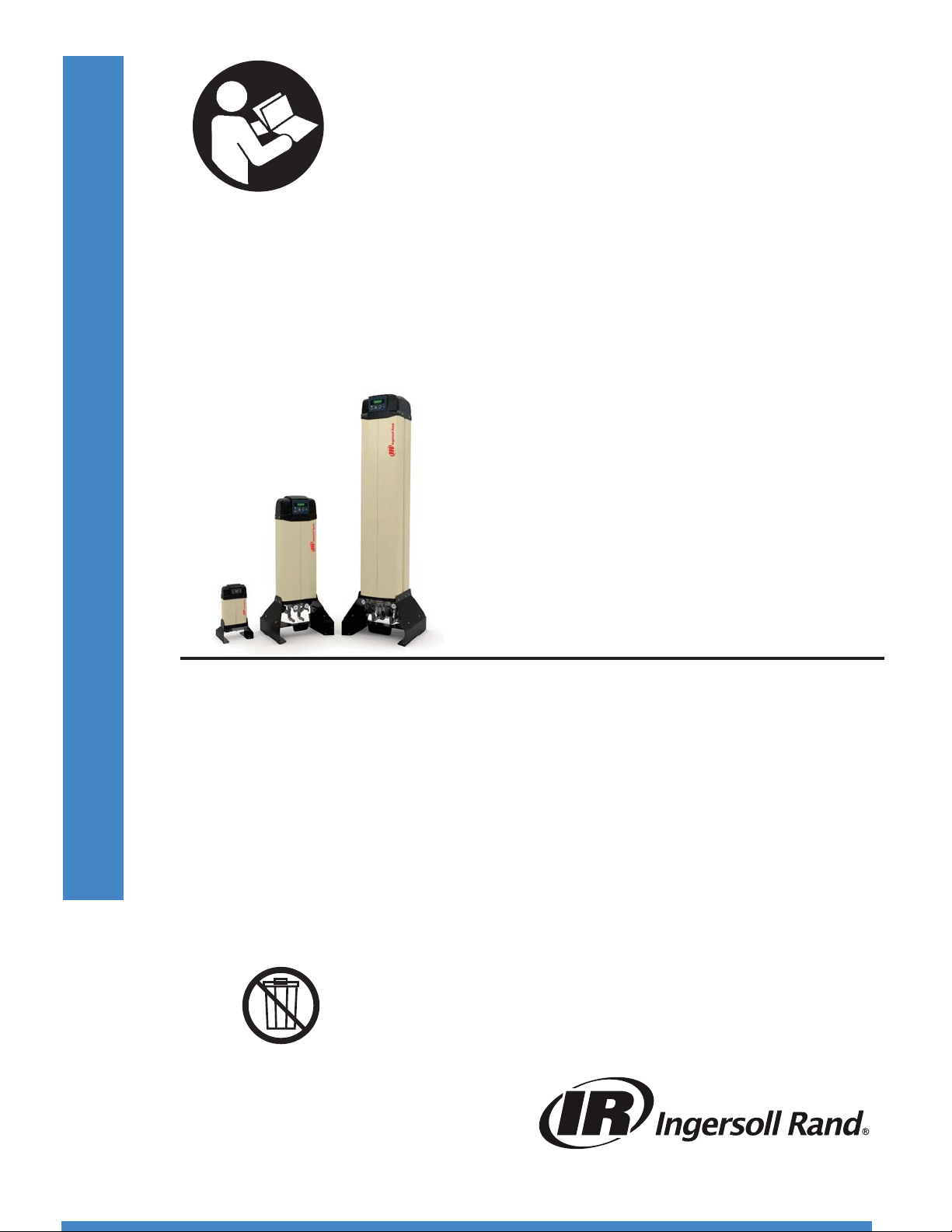
DA5IM, DA15IM, DA25IM
DA40IM, DA55IM, DA70IM, DA100IM, DA150IM
DA200IM, DA250IM, DA300IM
17933550
Revision D
June 2020
Installation, Operation, and Maintenance
Manual
Save These Instructions
Page 2

EN
A
T
PPROVED 11/Jun/2020 11:47:53 GM
CONTENTS
1.0 INTRODUCTION . . . . . . . . . . . . . . . . . . . . . . . . . . . . . . . . . . 3
2.0 ABBREVIATED WARRANTY . . . . . . . . . . . . . . . . . . . . . . . . 3
3.0 RECEIVING AND INSPECTION . . . . . . . . . . . . . . . . . . . . . . 4
3.1 INSPECTION ..............................................4
3.2 UNPACKING AND HANDLING .............................4
4.0 SAFETY AND OPERATION PRECAUTIONS . . . . . . . . . . . 5
4.1 SAFETY PRECAUTIONS LIST ...............................5
5.0 PRINCIPLES OF OPERATION . . . . . . . . . . . . . . . . . . . . . . . 6
5.1 INTRODUCTION ..........................................6
5.2 DRYING CYCLE ...........................................6
5.3 REGENERATION CYCLE. . . . . . . . . . . . . . . . . . . . . . . . . . . . . . . . . . . .6
5.4 REGENERATION AIR FLOW ................................6
5.5 TOWER REPRESSURIZATION ..............................6
5.6 VALVES ...................................................6
5.7 TIMING SEQUENCE .......................................6
5.8 COMPRESSOR INTERLOCK FUNCTION DA40IM DA300IM
ONLY ....................................................7
5.9 ENERGY MANAGEMENT SYSTEM .........................7
5.10 DRYER CONTROLS .......................................7
6.0 INSTALLATION AND STARTUP . . . . . . . . . . . . . . . . . . . 11
6.1 APPLICATION AND CHECK ANALYSIS ................... 11
6.2 LOCATING AND MOUNTING ............................ 11
6.3 PIPING .................................................11
6.4 FILTRATION ............................................. 12
6.5 ELECTRICAL CONNECTION ............................. 14
6.6 DEW POINT MONITOR EMS OPTION ................... 14
6.7 STARTUP PROCEDURE ................................. 14
6.8 DRYER SHUTDOWN SEQUENCE ........................ 16
7.0 MAINTENANCE AND SYSTEM CHECK . . . . . . . . . . . . . 17
7.1 SCHEDULED MAINTENANCE ............................ 17
7.2 PREFILTERS AND AFTERFILTERS ......................... 17
7.3 PILOT AIR CONTROL SOLENOID VALVES AND ......FILTER/
REGULATOR ............................................ 17
7.4 MUFFLER CHANGEOUT PROCEDURE .................... 17
7.5 ANGLE SEATED PURGE AND SWITCHING
VALVES ................................................. 18
7.6 DESICCANT CHANGEOUT PROCEDURE ................. 18
8.0 TROUBLESHOOTING . . . . . . . . . . . . . . . . . . . . . . . . . . . . . 19
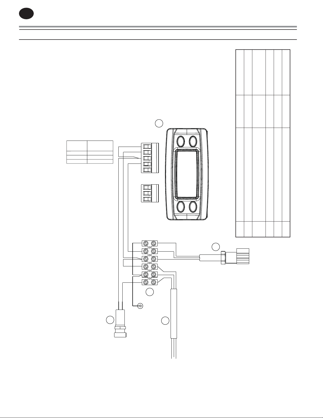
9.0 WIRING DIAGRAM . . . . . . . . . . . . . . . . . . . . . . . . . . . . . . . 20
9.1 DA5IMDA25IM, ELECTRICAL SCHEMATIC ...............20
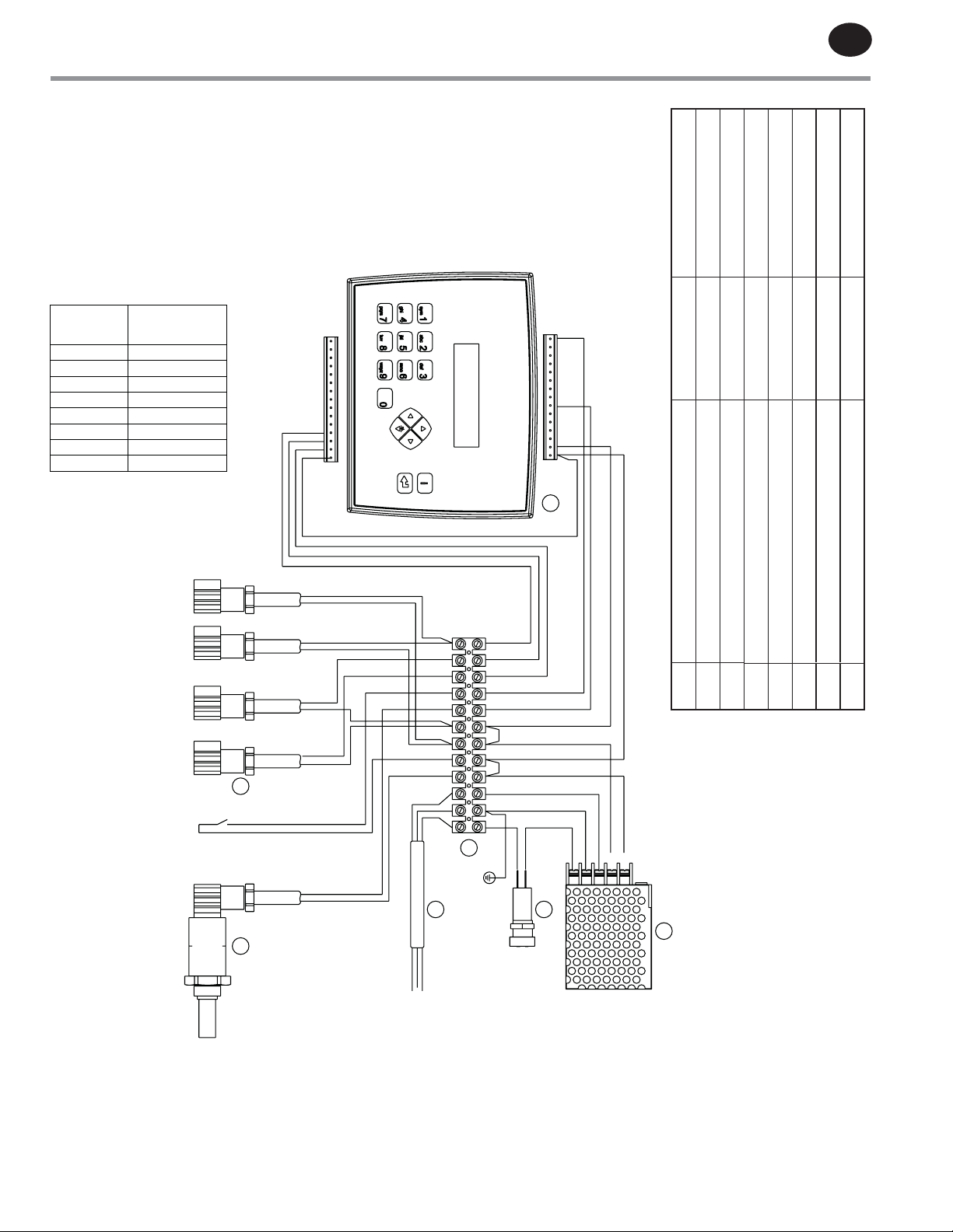
9.2 DA40IMDA300IM, ELECTRICAL SCHEMATIC ............21
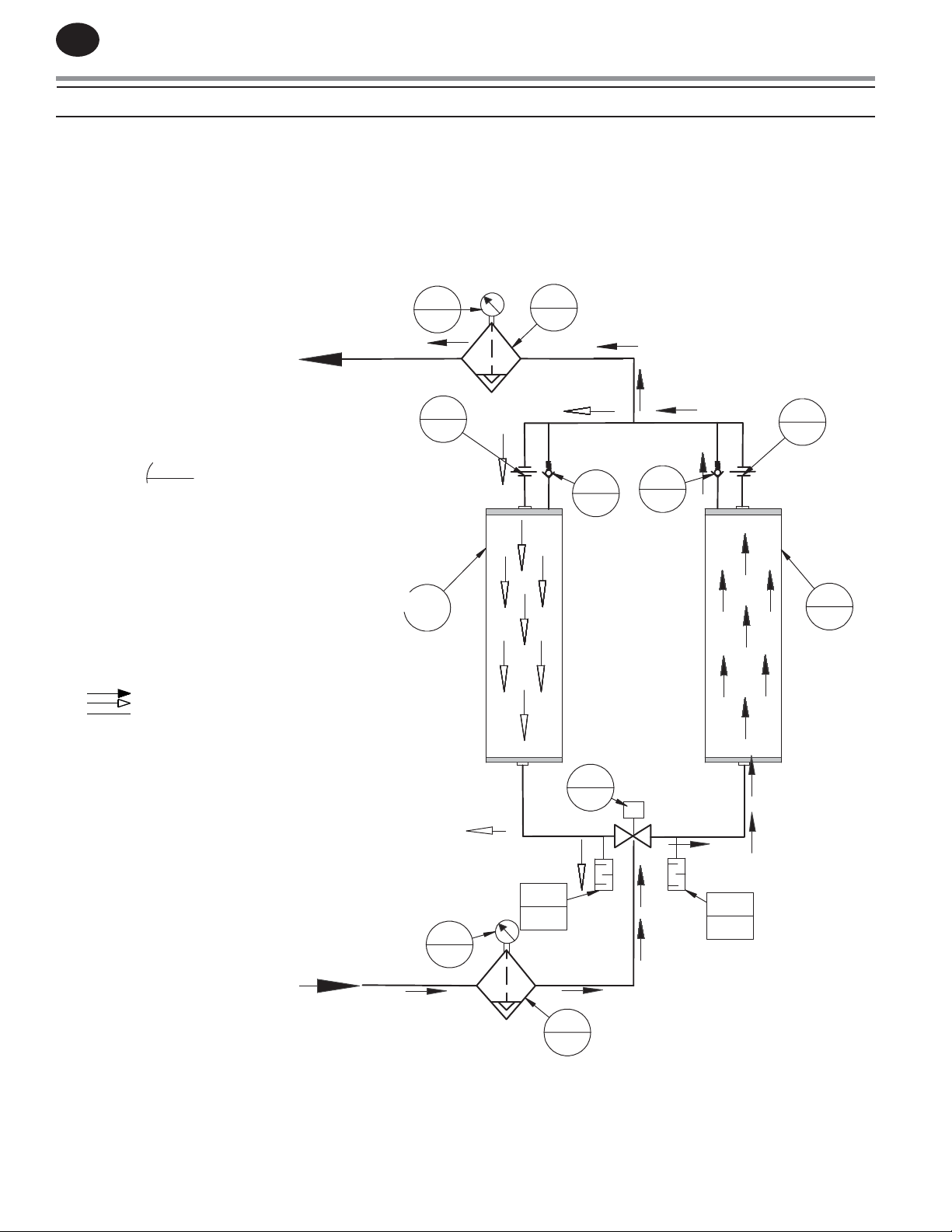
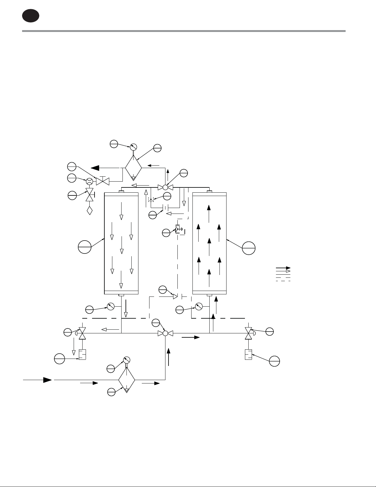
10.0 FLOW DIAGRAM . . . . . . . . . . . . . . . . . . . . . . . . . . . . . . . . 22
10.1 DA5IM DA25IM ...................................... 22
10.2 DA40IMDA150IM ..................................... 23
10.3 DA200IMDA300IM .................................... 24
11.0 ANGLE VALVE REBUILD PARTS . . . . . . . . . . . . . . . . . . 25
12.0 ENGINEERING SPECIFICATIONS . . . . . . . . . . . . . . . . . 26
12.1 ENGINEERING DATA 40°C ............................ 26
12.2 ENGINEERING DATA 70°C ............................ 27
Page 3

A
PPROVED 11/Jun/2020 11:47:53 GM
T
1.0 INTRODUCTION
EN
Ingersoll Rand DA Heatless Desiccant Dryers are designed
to adsorb moisture from compressed air. The DA dryers are
constructed with two towers that alternate between online
(drying) and oine (regenerating modes) in order to yield a
continuous stream of dry air at the dryer’s outlet. Each tower
contains desiccant beads.
During normal operation, wet air passes through the online
tower and water vapor from the air is adsorbed (collected) on
the desiccant beads. While air is being adsorbed in the online
tower, the moisture on the desiccant in the oine tower is
removed by a process called desorption (regeneration). After
an initial rapid depressurization, a portion of dried air from
2.0 ABBREVIATED WARRANTY
Ingersoll Rand heatless desiccant dryer products
are warranted to be free from defects in material and
workmanship for a period of 12 months from the original date
of shipment from the factory. To allow the warranty to be in
eect for 12 months from the date of equipment start-up, the
Warranty Registration Card must be completed and returned
to Ingersoll Rand. Alternately, the Warranty Registration
Card may be completed online at www.Ingersollrand.com.
The total warranty period cannot exceed 18 months from the
original date of shipment from the factory.
Equipment must be installed and operated in accordance
with Ingersoll Rand’s recommendations. Ingersoll Rand
liability is limited to repair of, refund of purchase price paid
for, or replacement in kind at Ingersoll Rand’s sole option
the online tower passes over the desiccant bed and carries
the moisture o the bed and out the dryer’s exhaust.
The continuous, alternating process of adsorption and
desorption is controlled using a timer that switches the
towers in a specic timed sequence. Very dry compressed air
dew points are achieved through the continuous switching
and operation of this dryer. Ingersoll Rand oers dryers to
provide either -40°F (-40°C) or -100°F (-70°C) pressure dew
point outlet air.
during the warranty time period stated above. IN NO EVENT
SHALL Ingersoll Rand BE LIABLE OR RESPONSIBLE FOR
INCIDENTAL OR CONSEQUENTIAL DAMAGES, even if the
possibility of such incidental or consequential damages has
been made known to Ingersoll Rand. In addition, the usual
maintenance and replacement type products are not covered
by this warranty. See SECTION 7.
The warranties expressed above are in lieu of and exclusive of
all other warranties. There are no other warranties, expressed
or implied, except as stated herein. There are no implied
warranties of merchantability or tness for a particular
purpose, which are specically disclaimed.
Page 4
EN
A
T
PPROVED 11/Jun/2020 11:47:53 GM
3.0 RECEIVING AND INSPECTION
3.1 INSPECTION
Upon receiving your Ingersoll Rand desiccant dryer, inspect
the unit closely. Evidence of rough handling should be noted
on the delivery receipt, especially in the case where the
dryer is not going to be uncrated immediately. Obtaining the
delivery person’s signed agreement to noted damages will
facilitate submission of insurance claims.
Contact your local sales oce to obtain an RMA claim to
initiate the return process (if required).
3.2 UNPACKING AND HANDLING
WARNING
Under no circumstances should any person attempt
to lift heavy objects without proper lifting equipment
(i.e. crane, hoist, slings or fork truck). Lifting any unit
without proper lifting equipment can cause serious
injury.
Refer to labels on the dryer for the appropriate means for
lifting or moving the dryer. When lifting the dryer, ensure
that no stress is applied to the piping or the valves. Refer to
SECTION 6.2 for locating and mounting of the dryer.
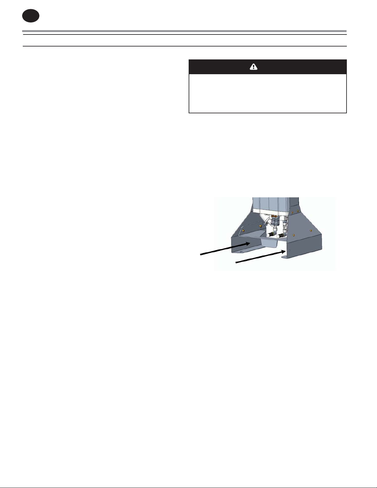
The dryer can be rigged using the forklift rails (See Figure1)
that are located on the bottom of the feet assembly. Use care
when inserting fork lift tongs beneath these rails to avoid
damage to piping at the rear of the dryer.
Figure: 1
Page 5
A
PPROVED 11/Jun/2020 11:47:53 GM
T
4.0 SAFETY AND OPERATION PRECAUTIONS
EN
4.1 SAFETY PRECAUTIONS LIST
Because an air dryer is pressurized and contains mechanical
parts, the same precautions should be observed as with
any piece of machinery of this type where carelessness in
operation or maintenance is hazardous to personnel. In
addition to the many obvious safety rules that should be
followed with this type of machinery, the safety precautions
as listed below must be observed:
1. Only qualied personnel shall be permitted to adjust,
perform maintenance or repair this air dryer.
2. Read all instructions completely before operating unit.
3. Pull main electrical disconnect switch and disconnect
any separate control lines, if used, before attempting to
work or perform maintenance on the unit. Use proper
lockout/tag out procedures.
4. Do not attempt to service any part while dryer is in an
operational mode.
5. When servicing this dryers, do not attempt to remove
any parts without rst relieving the entire air system of
pressure.
6. Do not operate the dryer at pressures in excess of its
rating.
7. Inspect unit daily to observe and correct any unsafe
operating conditions.
8. Dryer must be de-pressurized before servicing.
WARNING
“WARNING” is used to indicate a hazardous situation
which has some probability of death or severe injury.
Warning should not be considered for property damage
accidents unless personal injury risk is present.
CAUTION
“CAUTION” is used to indicate a hazardous situation
which may result in minor or moderate injury.
NOTICE
“NOTICE” is used to indicate a statement of company
policy as the message relates directly or indirectly
to the safety of personnel or protection of property.
Notice should not be associated directly with a hazard
or hazardous situation and must not be used in place of
“DANGER,” “WARNING,” or “CAUTION.”
NOTICE
The user of any air dryer manufactured by Ingersoll
Rand, is hereby warned that failure to follow the
included Safety and Operation Precautions can result
in personal injuries or equipment damage. However,
Ingersoll Rand does not state as fact, nor does it mean
to imply, that the preceding list of Safety and Operation
Precautions is all inclusive, and further, that the
observance of this list will prevent all personal injuries
or equipment damage.
Page 6
EN
A
T
PPROVED 11/Jun/2020 11:47:53 GM
5.0 PRINCIPLES OF OPERATION
5.1 INTRODUCTION
As described in SECTION 1, the DA series dryer is used to
remove water vapor from compressed air by diverting air ow
alternately between two towers that are lled with desiccant
material. While one tower processes the compressed air
stream by adsorbing water vapor, the opposite tower is
regenerated by desorbing the water vapor accumulated in
the previous cycle and venting it to atmosphere. Refer to
SECTION 10, FLOW DIAGRAM for a visual representation of the
drying and regenerating cycles.
Inlet ow to the dryer is directed to the bottom manifold
and the outlet ow exits through the upper manifold. The
manifolds are comprised of both pneumatically actuated
valves and check valves that direct compressed air ow
through the dryer.
5.2 DRYING CYCLE
Saturated compressed air enters the dryer and is directed
to the appropriate drying tower by the corresponding inlet
ow valves. The inlet ow valves are normally-open and one
of the valves will be actuated closed to direct the ow of
compressed air to the designated drying tower. It is important
to note that only one inlet valve is closed during this process.
The FLOW DIAGRAM in SECTION 10 depicts the scenario
where the left tower is being regenerated and the drying
process is occurring with the right tower. In this example, wet
compressed air enters the dryer and is directed to the right
tower for drying when the left tower valve is actuated to a
closed position. The normally-closed right tower purge valve
is closed while the left tower purge valve is actuated to an
open position during this period. As the compressed air ows
through the desiccant material on the right tower, removal
of water vapor from the air stream begins to occur through
adsorption.
5.3 REGENERATION CYCLE
Previously adsorbed moisture, removed from the process
stream, gets stripped or desorbed from the desiccant material
in the regeneration process. The rst stage of regeneration
is tower depressurization. After the inlet Flow Valves are
switched to divert air ow away from the regenerating
tower, the appropriate normally-closed purge valve will be
opened and the tower will be depressurized. Through rapid
depressurization, a signicant portion of the previously
adsorbed water vapor is stripped o the desiccant material
and exhausted to the atmosphere.
DA Heatless Dryers are equipped with a downstream purge
feature as standard. The downstream purge utilizes air from
a downstream source to purge the regenerating tower. This
feature is useful for applications with downstream (dry)
storage tanks, as pulling air from a downstream source can
minimize cycling of the air compressor.
5.4 REGENERATION AIR FLOW
To enable the desiccant media within the towers to be
thoroughly regenerated and to get proper dryer performance,
purge air ow is factory preset. Setting the purge ow too
high wastes compressed air and setting it too low results in
the dryer not achieving proper dew point performance.
NOTICE
Do not restrict purge exhaust ow in any way. Keep
purge muers clean. If exhaust air must be piped away
from dryer, consult factory for correct pipe sizing and
conguration.
5.5 TOWER REPRESSURIZATION
Upon completion of tower regeneration, and prior to the
inlet ow valves changing position to switch towers, the
regenerated tower must be repressurized.
Repressurization is accomplished when the appropriate purge
valve closes. Closing the purge valve allows the regeneration
air to begin to pressurize the tower.
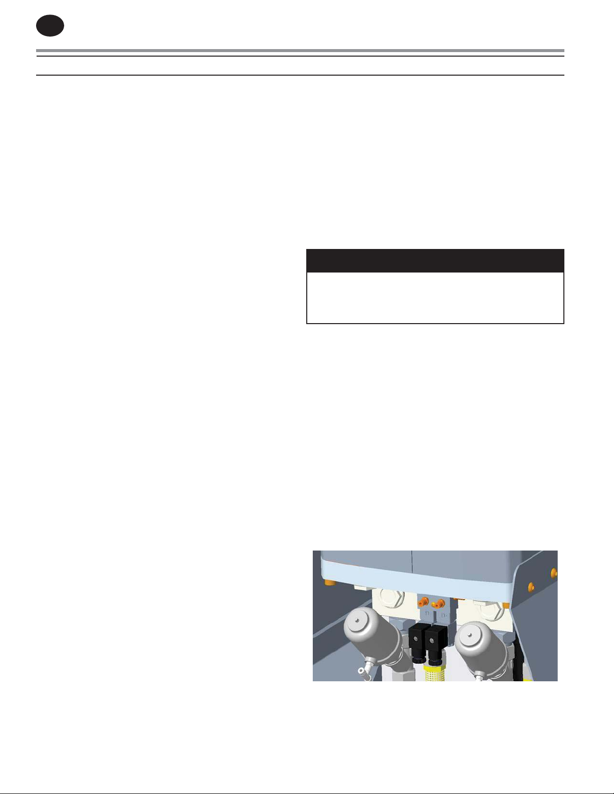
5.6 VALVES
Control air solenoid valves (See Figure 2) are used to actuate
the main ow valves and purge valves. The inlet ow
valves are normally-open valves, while the purge valves are
normally-closed valves. This arrangement permits air to ow
through the dryer in the event of power failure. The control air
solenoid valves are located on the bottom manifold assembly.
Figure: 2
The second stage of regeneration uses a portion of the
dry, compressed air expanded to atmospheric pressure to
complete the desorption process. As depicted in the FLOW
DIAGRAM, the compressed air exits the drying tower and
a portion of the air ows through the purge orice. Once
the air has passed through the purge orice, it expands
to atmospheric pressure and continues the regeneration
process. Desorption occurs as the desiccant releases water
vapor into the regeneration air that is then exhausted
through the purge muer.
5.7 TIMING SEQUENCE
A Digital Controller controls all dryer timing functions. The
timing of Ingersoll Rand -40°F (-40°C) and -100°F (-70°C)
dryers is outlined as follows:
Page 7
A
PPROVED 11/Jun/2020 11:47:53 GM
T
EN
5.7.1 TIMING CYCLE FOR -40°F (-40°C)
DEW POINT DRYERS
The standard timing cycle for -40°F (-40°C) operation switches
the inlet ow valve position every ve minutes which
alternates the drying tower. At the same time as a tower
inlet valve opens, the appropriate tower purge valve opens
to depressurize the regenerating tower. Tower regeneration
occurs for 4 minutes and 10 seconds, at which time the purge
valve closes to initiate repressurization.
5.7.2 TIMING CYCLE FOR -100°F (-70°C) DEW POINT
DRYERS
The standard timing cycle for -100°F (-70°C) operation
alternates the drying tower by switching the inlet ow valve
position every two minutes. At the same time a tower inlet
valve opens, the appropriate tower purge valve opens to
depressurize the regenerating tower. Tower regeneration
occurs for 1 minute and 50 seconds, at which time the purge
valve closes to initiate repressurization.
NOTICE
Do not restrict purge exhaust ow in any way. Keep
purge muers clean. If exhaust air must be piped away
from dryer, consult factory for correct pipe sizing and
conguration.
5.9 ENERGY MANAGEMENT SYSTEM
The Energy Management System (EMS) feature is designed
to minimize the use of purge air during low ow or low water
loading conditions. On -40°F (-40°C) units, a dew point sensor
samples the moisture content from the online tower and
provides a signal to the controller. This function utilizes a
dew point transmitter that monitors the dew point of the air
exiting the dryer. Please note that the dew point transmitter
should not be installed on a newly started machine until the
dryer has operated continuously for a minimum of 24 hours.
5.10 DRYER CONTROLS
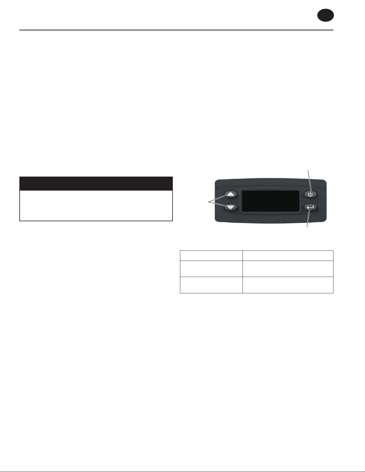
The dryer is controlled by a digital controller that includes an
illuminated display and keypad, accessible on the dryer main
panel.
DA5IM – DA25IM Models
ON/OFF
Button
UP/DOWN
Arrow key
LT RT
D D
250
R R
5.8 COMPRESSOR INTERLOCK FUNCTION
DA40IM DA300IM ONLY
The compressor interlock function enables the dryer to
reduce the timing of the purge cycle based on compressed
air demand. When the function is activated through the
TECHNICIAN MODE within the digital controller, the controller
monitors the cycle rate of the air compressor load/unload
relay. The dryer will need to be eld wired to the normallyopen contact of the air compressor to allow the controller to
monitor the cycle rate. The compressor interlock connections
are depicted on the dryer wiring diagram (SECTION 9, Wiring
Diagram).
It is important to note that the compressor interlock function
is designed to be operated independent from the Energy
Management System (EMS) option. For dryers equipped with
the EMS option, the compressor interlock must be set to “OFF”
in order to activate the EMS function. Setting the compressor
interlock to “ON” in TECHNICIAN MODE will disable the EMS
function.
For dryers equipped with the EMS option, the compressor
interlock function can be used as a backup method to
reduce purge air consumption when the dew point monitor
is removed for calibration or for service. It is important to
note that the performance of the dryer is based on the inlet
temperature and pressure conditions along with ow. If the
inlet temperature of the compressed air being supplied to the
dryer is above 100oF (38°C), the user must exercise caution
in order to prevent the desiccant beds from becoming
overloaded, possibly requiring the compressor interlock
function to be de-activated. Consult the factory for higher
inlet temperatures (101°F/38°C - 120°F /49°C). Dryer sizing is
aected by increased inlet temperatures.
CONTROLLER BUTTONS AND KEYS
ON/OFF Button Press 2 seconds
Set up Menu Button To enter cycle time setting
UP/DOWN Arrow key To change cycle time
When the dryer is actively cycling LT or RT and R or D will
illuminate to indicate working phase of each tower. The
numeric countdown timer indicates seconds remaining in the
operating sycle step.
If cycle times need to be adjusted to meet site conditions,
a trained service technician must be the one to make the
changes.
Set up Menu
Page 8
EN
A
T
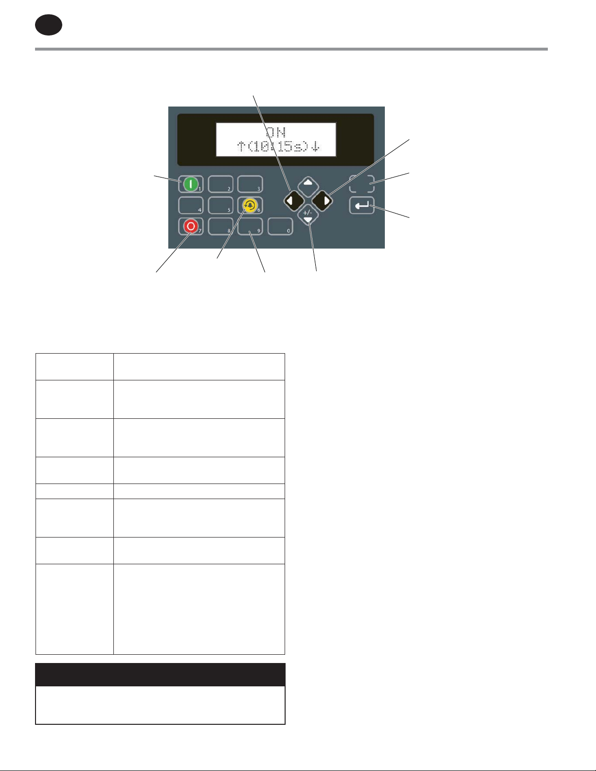
DA40IM – DA300IM Models
PPROVED 11/Jun/2020 11:47:53 GM
BACK NAVIGATION
KEY
FORWARD NAVIGATION
KEY
ON/RESUME
BUTTON
RESET BUTTON
OFF BUTTON NUMERAL KEYS
CONTROLLER BUTTONS AND KEYS
INFORMATION
BUTTON
ON/RESUME
BUTTON
OFF BUTTON
NUMERAL KEYS
RESET BUTTON Exit current screen.
+ / - BUTTON
ENTER BUTTON
NAVIGATION
KEYS (ARROWS)
Restricted Level access - for factory use
only.
Initiates Dryer Operating Cycle. Begins
system monitoring and valve switching
functions.
Stops Dryer Operating Cycle. Stops valve
switching functions. Initiates Shutdown
Sequence. Dryer remains pressurized.
Allow the operator to enter values for
selectable settings and assignments.
Use to toggle or change multistate
variables. Also allows entering negative
numbers in numeric input variables.
Use to change and accept set point
values.
Enables navigation between screens
and lines.
On models DA40IM – DA300IM Multiple
screens can be viewed. Use the BACK
(left) and FORWARD (right) navigation
keys to navigate within dierent
screens.
INFORMATION
BUTTON
ENTER
BUTTON
+ / - BUTTON
5.10.1 DRYER ALARMS
DA5IM – DA25IM do not oer any alarms.
DA40IM – DA300IM oer predened elapsed time alarms,
that can be reset by pressing the "Reset" button.
1. Filter element change – 6 months
2. Muers – 12 months
3. Dew point sensor – 12 months
4. Valves – 36 months
5. Desiccant change – 48 months
5.10.2 DRYER COMMUNICATION RS485
(DA40IM - DA300IM)
1. RS485 port
2. RS485 connector signals
• D+ Tx/Rx+ (B)
• D- Tx/Rx– (A)
• T+ Positive Termination
• T- Negative Termination
• SG Signal Ground
NOTICE
In order to ensure proper tower pressurization, every
dryer ON (restart) has 30 seconds delay incorporated
into software. Countdown is visible on PLC main screen.
On models DA40IM – DA300IM Multiple screens can be
viewed. Use the BACK (left) and FORWARD (right) navigation
Page 9
A
PPROVED 11/Jun/2020 11:47:53 GM
T
EN
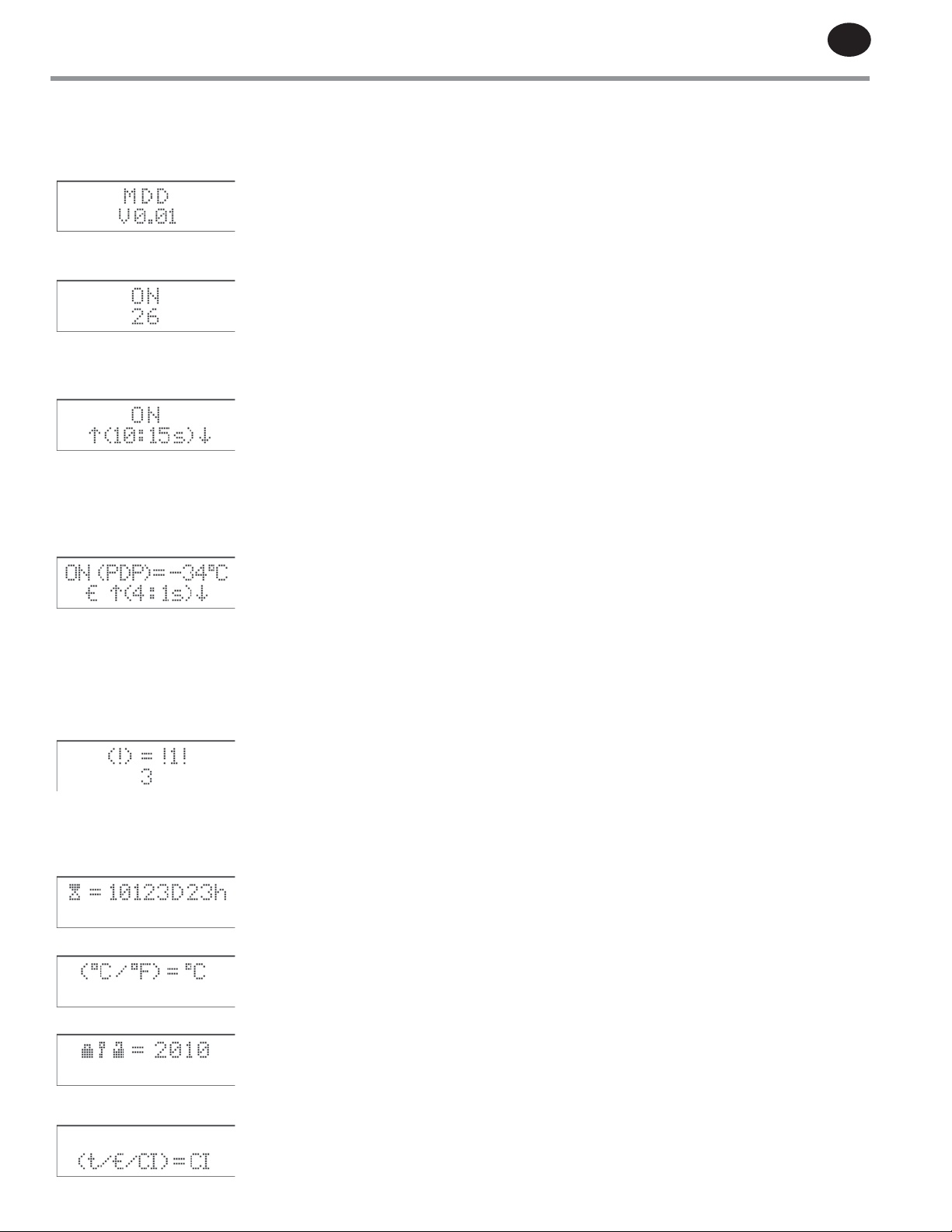
5.10.3 CONTROLLER DISPLAY SCREENS
Visual display of dryer status, Operating Cycle information, conguration, and Alarm status.
INITIALIZATION (Screen appears briey when electrical power is initially supplied to the dryer.)
LINE 1: Intentionally left blank.
LINE 2: Dryer Operating Program Version
ANTI-SHORT-CYCLE (30-second delay that occurs any time the dryer is turned o.)
LINE 1: Dryer operating status (ON or OFF)
LINE 2: Anti-Short-Cycle countdown (seconds remaining)
HOME (Screen appears after ON button (green) has been pressed. Screen indicates Operating Cycle Step information and dryer
conguration. Use forward NAVIGATION KEY to advance to Operating screens.)
LINE 1: Dryer operating status (ON or OFF).
LINE 2: Dryer Operating Cycle Step number (1-10). Seconds Remaining in Step.
UP Arrow indicates Drying Flow (Left Tower). Down Arrow indicates Regeneration Flow
(Right Tower). (Arrows will switch at time of tower changeover.)
IF EQUIPPED WITH DEW POINT TRANSMITTER (when Energy Management System (EMS) option
is installed):
LINE 1: Dryer operating status (ON or OFF). Outlet compressed air Pressure Dew Point (PDP)
during operation.
LINE 2: EMS is activated (blinking) - dryer operating in standby mode.
Interrupted Step number remains visible. Countdown timer pauses.
UP Arrow indicates Drying Flow (Left Tower). Down Arrow indicates Regeneration Flow
(Right Tower). (Arrows will switch at time of tower changeover.)
OPERATING STATUS (Screens indicate normal Operating Cycle information and Alarm states. Press forward NAVIGATION KEY
to advance through screens. Press back NAVIGATION KEY to return to HOME screen.)
LINE 1: Dryer Alarm Status: 0 = No Alarm; 1 = Dryer in Alarm state
LINE 2: Appears blank if no Alarm condition exists. Press ENTER to view Alarm menu.
If in Alarm state, the condition will be indicated: 1 - 3 = Alarms; 4 - 8 = Service
Reminders.
See ALARM STATUS AND SERVICE REMINDERS on next page.
LINE 1: Total Operating Time: Days/Hours
LINE 2: Intentionally left blank.
LINE 1: Temperature Scale: Use +/- button to select degrees Celsius or degrees Fahrenheit
LINE 2: Intentionally left blank.
LINE 1: Protected Settings: Enter Password to access: Technician Mode (TM) = 2010; Service
Reminders = 4040
LINE 2: Intentionally left blank.
LINE 1: Intentionally left blank.
LINE 2: Operating Mode: Use +/- button to select: t = Timed;
ࣅ = Energy Management System (EMS); CI = Compressor Interlock
Page 10
EN
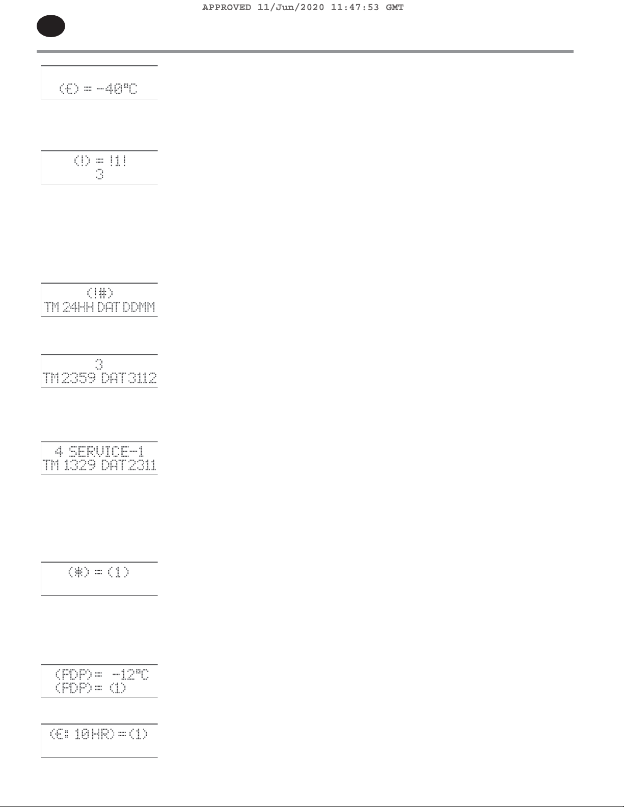
LINE 1: Intentionally left blank.
LINE 2: Optional Energy Management System (EMS) temperature setpoint
ALARM STATUS AND SERVICE REMINDERS (Annunciation of Dryer Operating Fault Conditions.)
ALARMS
LINE 1: Dryer Alarm Status: 0 = No Alarm; 1 = Dryer in Alarm state
LINE 2: Current Alarm condition: 1 = High Pressure Dew Point (PDP); 2 = Energy Management
System (EMS) o;
3 = Pressure Dew Point (PDP) out of range; 4 = Replace lter element;
5 = Replace exhaust muers; 6 = Replace pressure dew point sensor; 7 = Replace
valves;
8 = Replace desiccant media)
ALARM HISTORY FORMAT
LINE 1: Alarm identier number
LINE 2: Time and Date format
EXAMPLE - RECORDED ALARM
LINE 1: 3 = Pressure Dew Point (PDP) out of range
LINE 2: Time and date of the occurrance
Press ENTER to view the next recorded alarm.
SERVICE REMINDERS (Accessible through Protected Settings screen.)
LINE 1: Dryer service requirement: 0 = No service needed; 1 = Service required
LINE 2: Service descriptions:
4 = Replace lter element (SERVICE-1), 6 months
5 = Replace exhaust muers (SERVICE-2), 12 months
6 = Replace pressure dew point sensor (SERVICE-3), 12 months
7 = Replace valves (SERVICE-4), 36 months
8 = Replace desiccant media (SERVICE-5), 48 months
TECHNICIAN MODE (Accessible through Protected Settings screen.)
LINE 1: Dryer Restart following power outage. Use +/- button to select:
0 = MANUAL - Press ON button (green). Dryer will start at the beginning of the
Operating Cycle. 1 = AUTOMATIC - Dryer will automatically restart and operation will
resume at the Step in the Operating Cycle that was active before the power outage
occurred.
LINE 2: Intentionally left blank.
LINE 1: Pressure Dew Point high temperature alarm setpoint. Use numeral keys to change
temperature value. Press ENTER button to input the new setpoint.
LINE 2: Use +/- button to select: 0 = O; 1 = On
LINE 1: Energy Management System (EMS) operating time limit (preset 10-hour limit).
LINE 2: Use +/- button to select: 0 = O; 1 = On
Page 11
A
PPROVED 11/Jun/2020 11:47:53 GM
T
6.0 INSTALLATION AND STARTUP
6.1 APPLICATION AND CHECK ANALYSIS
To achieve the best dryer performance, you should carefully
check that the design and installation requirements outlined
below are satised.
NOTICE
The standard dryer is not rated for any gas other than
air.
The dryer is designed to be operated with a compressed air
inlet temperature ranging from 68°F (20°C) to up to
120°F (49°C) and at an operating pressure ranging from
60psig (4barg) to 200psig (14barg). The volume of air will
be dependent on the system operating pressure. The air
compressor delivering air to the dryer must be sized properly
to handle both the demand and the purge air requirements
necessary for regeneration.
EN
6.2 LOCATING AND MOUNTING
Use a forklift to lift the dryer only at the lift points identied
with labeling. Use care to avoid damage to the manifold
assembly. Bolt the dryer to the foundation using the bolt
holes provided in the base frame. Anchor bolts should
protrude a minimum of 1 inch (25 mm) above the foundation.
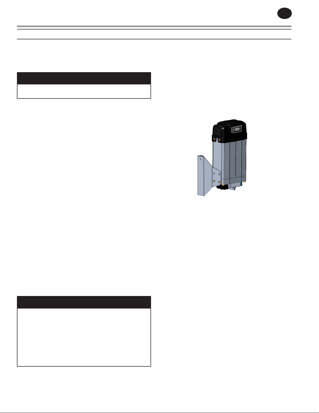
Models DA5IM-DA25IM can be wall mounted (See Figure 3).
Use appropriate size bolts to hold entire dryer weight.
Figure: 3
The factory should be consulted if the dryer is to be operated
at pressures below 60psig (4barg) to verify sizing and proper
conguration.
The standard dryer is rated to operate at an inlet temperature
and pressure of 100°F (30°C) @ 100psig (7barg). The
operating conditions should be veried prior to installing
and operating the dryer to ensure it is properly sized. A dryer
with greater capacity may be required to achieve expected
dew point performance in installations with elevated inlet air
temperatures. Lower inlet temperature conditions may also
reduce dryer performance.
It is important to note that delivering lower compressed air
inlet temperature levels will reduce drying performance. A
minimum compressed air inlet temperature of 68°F (20°C) is
required to be supplied to the dryer for proper operation.
The dryer should generally be installed in an enclosed area
where the ambient temperature does not drop below
50°F (10°C) and is not above 115°F (46°C). Please consult the
factory for outdoor installation applications where additional
provisions may be required for lower ambient conditions.
NOTICE
Ingersoll Rand recommends the muers be cleaned
after initial start-up to remove any desiccant dust
generated during dryer shipment. After running the
dryer for the initial 30 minute period, de-energize/
depressurize the dryer and remove the muers.
Disassemble and clean the removable insert inside the
muer core. Reinstall the muers prior to operating
dryer. Periodic inspection of the muers is required to
ensure proper dryer operation.
6.3 PIPING
Pipe the compressed air lines to the inlet and outlet
connections. When installing the prelters, which are shipped
loose in the package, the prelters should be located as
close to the dryer as possible. In addition, they should be
positioned to allow for ease of service.
Note that the wet air inlet is at the dryer’s lower manifold,
while the dry air outlet is at the dryer’s upper manifold. In
situations where air supply is required 24 hours a day (where
it is undesirable to interrupt the compressed air ow), an
optional three valve by-pass system is recommended to
bypass the dryer. To keep pressure drop at a minimum,
the fewest elbows possible should be used. In order to
prevent ooding of the desiccant bed when the dryer is o,
the bypass should be used when troubleshooting the air
compressor operation or when servicing the dryer.
Once all piping has been connected, all joints, including those
on the dryer, should be soap bubble tested at line pressure
to ensure no joints have been damaged in transit and during
site placement. All installed piping must be self-supported.
The dryer manifold piping cannot be used to support the
interconnecting piping.
A minimum inlet temperature of 68°F (20°C) is required for
proper dryer operation.
Page 12
EN
A
T
PPROVED 11/Jun/2020 11:47:53 GM
6.4 FILTRATION
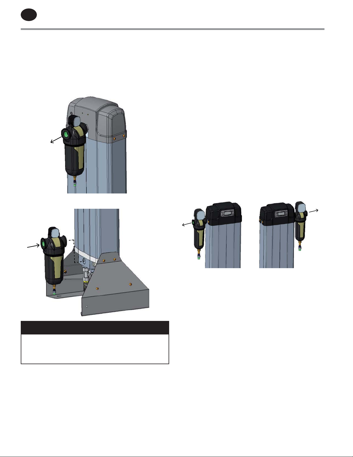
NOTE: A prelter and an afterlter are provided with your
dryer. Afterlters can be directly mounted on the dryers
outlet while prelters need additional piping to allow the
height to be sucient for maintenance purposes (See Figure
4 & 5).
Figure: 4
Figure: 5
Located before the dryer, coalescing prelters protect the
desiccant beds from contamination from oil, entrained water,
pipe scale and other contaminants. This extends the dryer’s
desiccant life.
Prelters should be located as close to the dryer as possible
and must be provided with drains to prevent liquid water
from entering the desiccant beds. Drain maintenance is not
covered by the standard warranty.
It is recommended that a mechanical separator with
a properly functioning drain be installed immediately
preceding the prelter to remove bulk liquid and entrained
water.
The particulate/coalescing afterlter, located after the dryer,
helps eliminate the possibility of desiccant dust carryover into
the air system. To ensure proper dryer operation, the prelter
drain(s) must be inspected periodically.
The outlet lter on models DA5IM – DA25IM can be mounted
on left or right outlet connection (See Figure 6) while the
opposite connection must be plugged.
Figure: 6
NOTICE
All DA model dryers must have proper ltration. Liquid
water and oil must be removed before compressed
air enters the dryer. Ensure Prelters and drains are in
good working order. Failure to do so will void warranty.
Page 13
A
PPROVED 11/Jun/2020 11:47:53 GM
T
EN
6.4.1 FILTER DRAIN VALVE
DA dryer models are furnished from the factory with lters
that include an automatic condensate drain valve. The drains
require periodic inspection and maintenance to ensure
proper dryer operation. Drain maintenance is not covered by
the standard warranty.
Filters include an automatic drain valve. The drain valve must
be checked for correct conguration prior to pressurization of
the dryer as follows:
• Filters must be oriented vertically for proper operation.
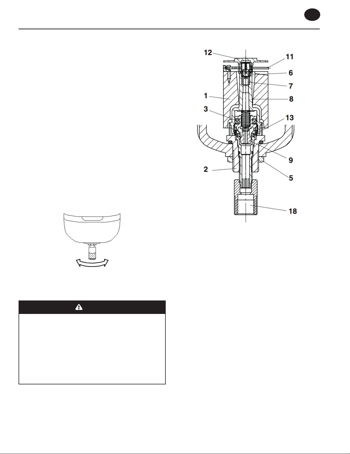
• The drain stem must be properly adjusted as follows:
- Twist the drain stem (No. 18 in Figure 8) to set for
AUTOMATIC (Normal) or MANUAL (Test) operation
(See Figure 7 below).
- Twist the stem fully clockwise (when viewed from the
bottom of the lter bowl) for AUTOMATIC draining of
condensate. This is the Normal position.
- Twist the stem fully counter-clockwise (when viewed
from the bottom of the lter bowl) for MANUAL
draining of condensate (Test/Bleed) or if connected to
an external drain.
Figure 8
Figure 7
MANUAL
AUTOMATIC
Minimum operating pressure of 22psig (1.5barg) is required
for the oat that is within the drain assembly to seat properly.
Pressures below 22psig (1.5barg) allow air to escape from the
drain when the compressed air system is being pressurized.
WARNING
Proper safety precautions must be followed when
servicing lters and drains. Filter bowl must be
de-pressurized before servicing drain.
Service should only be performed by qualied
personnel.
Before rst-time use, and after maintenance, the
drain stem (See 18 in Figure 8) should be twisted fully
clockwise to provide AUTOMATIC operation
(See Figure 7).
Method of Operation (See Figure 8)
• When the lter pressure is below 22psig (1.5barg), the
piston (9) is held in an open position by the spring (3).
• When the lter is pressurized above 22psig (1.5bar), the
piston closes the drain aperture at the O-ring (13).
• As the condensate collects in the lter bowl, the oat (1)
is pushed upward, opening the nozzle (7) and allowing air
to reach the top of the piston (9). This causes the piston to
move downward, opening the aperture at the O-ring (13)
for drainage of the condensate.
Maintenance and Initial Operation
• After initial startup, inspect drain(s) for system debris.
Clean as required. Float drain assembly is screwed into the
bottom of the bowl from the inside.
• Drains require periodic inspection and maintenance to
ensure proper operation. Clogging of drains due to system
debris or fouling is not considered warranty. Faulty drains
must be returned to the factory for analysis in order to
receive warranty credit.
Clogged drain screens can be cleaned by immersing the drain
in a detergent and rinsing thoroughly in water.
Page 14
EN
A
T
PPROVED 11/Jun/2020 11:47:53 GM
6.5 ELECTRICAL CONNECTION
Make all electrical connections to the dryer as shown on the
wiring diagram (SECTION 9). Care must be taken to connect
the proper voltages.
NOTICE
Dryer must be grounded with the full size ground wire
connected to an earth ground.
NOTICE
Dryer must be fused according to NEC with the size fuse
listed on the dryer serial nameplate, or on specication
sheet in Technical Manual.
Size eld connection knock-out for the conduit tting
required by the NEC. Installer must use UL Type 4 rated tting.
The compressor interlock wiring should be veried if this
function is to be activated at start-up.
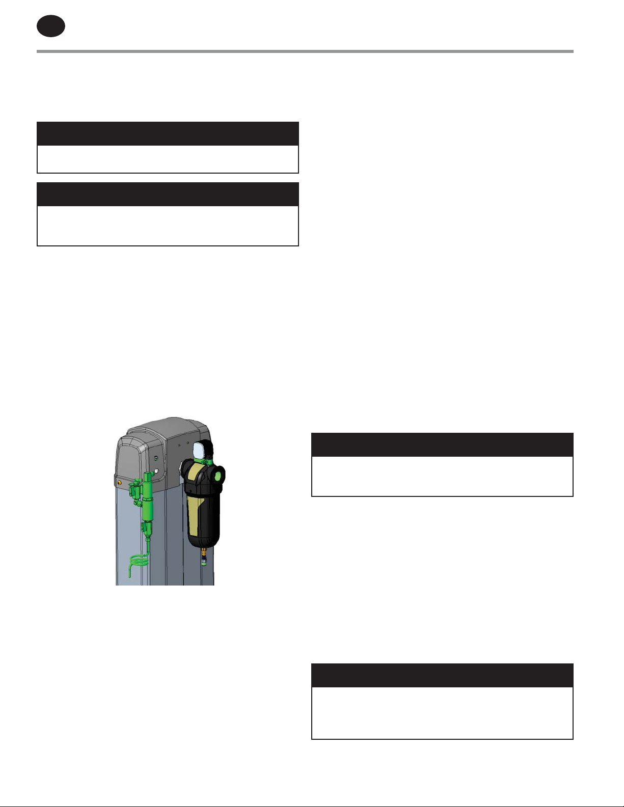
6.6 DEW POINT MONITOR EMS OPTION
The dew point transmitter assembly (See Figure 9) that is
supplied with the dryer as a separate component (when the
dryer is ordered with the EMS option) must not be installed
until the dryer has been in operation for 24 hours.
Figure 9
6.7 STARTUP PROCEDURE
A Startup Form (included with the manual) must be
completed and submitted with the Warranty Card as part of
the commissioning process. This is included with the dryer at
shipment.
Prior to pressurizing the compressed air system, conduct a
visual inspection of the dryer to verify that the unit was not
damaged during the installation process. This includes:
• Inlet and outlet compressed air piping connections are
properly supported.
• Extruded pressure vessels are not damaged.
• Gauges are in good condition.
• Pneumatic control air hoses, inlet and outlet compressed
air piping connections are properly supported and
tightened.
• Prelter and afterlter bowl are properly tightened.
• Drain lines are installed to the lters. Refer to SECTION
6.4.1.
• Fasteners securing the dierential pressure indicator to
lter head are secured.
• Drain stem on each lter bowl is placed in the proper
direction such that it operates in the manual mode for
initial startup. Refer to SECTION 6.4.1. The drains will allow
air to escape until the system reaches 22psig (1.5barg) at
which point the internal oat will seat properly and the
drain will seal closed.
The dryer warranty will be voided if the dew point transmitter
is damaged as a result of ooding condition.
NOTICE
The Dew Point Transmitter that is supplied with the
dryer as a separate component must not be installed
until the dryer has been in operation for 24 hours.
After the visual inspection is complete, slowly pressurize the
dryer and perform a verication check on the following items:
1. Verify that the air outlet shut-o valve is closed (if this
is provided for the dryer). This can be provided as part
of a three-valve bypass option for the dryer or eld
provided as part of the installation.
2. Check for air leakage prior to initiating ow through
the dryer. Repair all leaks prior to starting the dryer.
In order to maintain the drying performance of the
dryer, any leaks must be xed; most important are
leaks identied on the outlet side of the dryer.
NOTICE
DO NOT FLOW COMPRESSED AIR THROUGH THE DRYER
WHEN THE DRYER IS OFF. The desiccant beds will
become ooded with moisture and the Warranty will be
voided.
Page 15
A
PPROVED 11/Jun/2020 11:47:53 GM
T
EN
3. Verify that the prelter drain is blowing freely to
drain residual water in the system. If no moisture is
observed exiting the drain, turn drain stem to the
automatic position. Verify drains ahead of dryer are
functioning properly.
4. Turn the eld disconnect switch to the ON position
to apply power to the dryer. This will energize the
controller. Use proper PPE to verify that the voltage
to the control panel matches the voltage/phase listed
on the serial plate of the dryer. Do not apply power
to the dryer until items 1-4 listed above have been
veried. Do not apply power to the dryer or activate
the dryer for operation until the air system checks are
completed.
• For dryers equipped with the EMS option, do
not install the dew point transmitter until the
dryer has operated for a minimum of 24 hours to
reach steady state conditions. See the Warning
note regarding installation of the dew point
transmitter. Failure to follow this procedure will
damage the dew point sensor and will void the
sensor warranty.
5. The control air regulator located inside the top cover
is preset to not exceed 100psig (7barg). The main
ow inlet and purge valves are regulated to operate
with a control air pressure level not to exceed 145psig
(10barg).
after the dryer is placed into operation. Drain
maintenance or cleaning of system debris is
not covered under warranty. Improper drain
maintenance will result in damage to the
desiccant beds and will void the warranty.
• Once the system has operated for approximately
two hours, the muers will need to be inspected.
Follow proper safety procedures prior to
replacing the muers. Muers are consumable
items and are not warranted other than for
manufacturing defects.
• Monitor the operation of the dryer and contact
Ingersoll Rand if any problems arise during the
startup process. The oat drains on the dryer's
should be inspected daily to ensure proper
operation.
• For dryers equipped with the EMS option, install
the dew point transmitter once the dryer has
operated for a minimum of 24 hours and the BMI
is fully blue in color. After the sensor has been
installed, re-activate the EMS function through
the settings screen.
• Verify (if wired) compressor interlock Function.
See SECTION 5.8.
9. Complete the warranty startup card after the dryer is
fully commissioned.
6. Press the ON button on the dryer controller to initiate
dryer operation.
• Observe the operation of the dryer and verify
that the dryer sequence is operating properly.
The dryer controller will automatically sequence
the valves. Do not allow the dryer to operate if
problems are observed.
• Slowly open the outlet air shut-o valve (if
equipped) and allow the system to slowly
pressurize.
7. Verify that the compressed air system remains
pressurized.
NOTICE
At initial start-up, check the dryer operation for one
or two cycles, especially at the time of the tower shift.
Verify that all systems are operating in their proper
order and sequence. If the dryer is not functioning
properly, contact distributor or Ingersoll Rand Technical
Service.
8. Verify the Technician and Maintenance settings of the
dryer. Refer to SECTION 5.10 for further instructions.
• Verify that the oat drain(s) on the inlet lters
are operating properly. It is important to note
that debris from the system piping may interfere
with the operation of the oat drain and it is
the responsibility of the installer to verify this
Long-Term Storage
If a dryer has been in storage for an extended period of time,
follow the instructions above to start the dryer. Depending
on the amount of time the unit was in storage, it may take
between 8 and 12 hours before dryer would be regenerated.
NOTICE
When opening the outlet valve, ensure drying tower
gauge maintains line pressure. Allowing the pressure
in the dryer to drop will result in an overow condition
and potentially cause valves to stop functioning.
NOTICE
-100°F (-70°C) dryers require ow through the dryer to
lower the pressure dew point to design levels. Failure to
permit air ow through dryer (deadheading) will result
in elevated outlet dew points. Once air is permitted
to ow through the dryer, the pressure dew point will
gradually reduce to design levels.
Page 16

EN
A
T
PPROVED 11/Jun/2020 11:47:53 GM
6.8 DRYER SHUTDOWN SEQUENCE
The following procedures must be followed to correctly
terminate dryer operation:
NOTE: The DA dryer must remain pressurized during the
shut-down sequence.
- Press the red “OFF” button to deactivate the dryer operating
sequence and de-energize the control valves. The main ow
valves will be positioned to the default position:
a.The purge valve will close
b.The regenerating tower will re-pressurize
c.The main inlet ow valves will open
The system must remain pressurized in order for the main
ow valves on the dryer to revert to the default position.
- The status line in the home screen will display “OFF”.
- The system will remain pressurized at all times. The dryer
does not contain any provisions to permit a system bleed
down.
- The red “OFF” button only de-activates the dryer operating
sequence - electric power will remain live within the dryer
main panel.
WARNING
Failure to follow this procedure may result in the system
retaining pressure within the dryer and potentially
result in an unsafe condition for service personnel.
NOTICE
DO NOT FLOW COMPRESSED AIR THROUGH THE DRYER
WHEN THE DRYER IS OFF. The desiccant beds will
become ooded with moisture. The dryer Warranty will
be void.
Page 17
p
7.0 MAINTENANCE AND SYSTEM CHECK
EN
7.1 SCHEDULED MAINTENANCE
DAILY MAINTENANCE FUNCTIONS:
• Check and record inlet pressure, temperature and ow.
Verify that it is within specications.
• Check tower pressure gauge readings are within operating
tolerance (DA40IM - DA300IM only).
• Check dryer operation for proper cycling, depressurization
and re-pressurization.
• Check that the prelter drain is operating properly and that
there is no condensate discharged from purge muers.
• Verify that pressure in purging tower is 3psig (0.2barg) or
less. If higher, muer replacement is recommended. See
SECTION 8.
• Check the dryer digital controller for alarms (DA40IM –
DA300IM only).
• Verify that prelter and afterlter dierential pressure
is within operating limits. Replace elements and/or
cartridges as required.
MONTHLY MAINTENANCE FUNCTIONS:
• Check condition of muers by reading tower pressure
gauge when the tower is in the re-generation cycle. If
pressure is above 3psig (0.2barg), muer replacement may
be required.
7.2 PREFILTERS AND AFTERFILTERS
PREFILTERS - The cartridges of the prelter must be changed
as often as required to prevent contamination of the
regenerative dryer’s desiccant bed.
The prelter and automatic drain must be checked daily.
To prolong lter cartridge life, it is recommended that a
mechanical air/moisture separator be placed immediately
before the prelter.
AFTERFILTERS - The purpose of the afterlter is to remove
residual desiccant dust. Depending upon equipment
application and usage, frequency of lter element change
will vary. It is recommended that, at the minimum, the lter
element be changed every six months.
7.3 PILOT AIR CONTROL SOLENOID VALVES AND
FILTER/REGULATOR
The length of time the pilot air valves can reliably operate
without replacement is dependent upon the dryer operating
cycle. On Ingersoll Rand -40°F (-40°C) dew point dryers,
replacing the valves every 36 months is recommended. For
-100°F (-70°C) units, it is recommended that the pilot valves
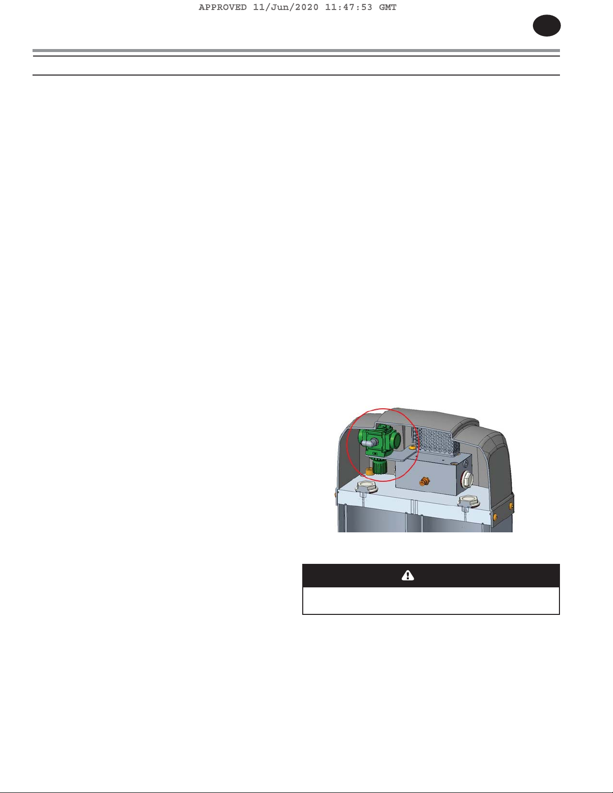
be replaced every 24 months. The control air regulator (See
Figure 10) should be set for 100psig (7barg).
Figure: 10
NOTE: Ingersoll Rand recommends the muers be cleaned
after initial start-up to remove any desiccant dust generated
during dryer shipment. After running the dryer for the initial
30 minute period, de-energize/depressurize the dryer and
remove the muers. Disassemble and clean the removable
insert inside the muer core. Reinstall the muers prior to
operating dryer. This procedure should be repeated within
the rst seven days of dryer operation.
SEMI-ANNUAL MAINTENANCE FUNCTIONS:
• Check outlet dew point (EMS option only).
• Replace prelter and afterlter elements and/or cartridges.
ANNUAL MAINTENANCE FUNCTIONS:
• Check desiccant and replace if necessary.
• Inspect and clean pilot air control solenoid valves, check
valves and ow valves. Rebuild and / or replace as required.
• Replace drains on prelter and afterlter.
• Test electrical components, replace as necessary.
• Check for loose electrical wiring connections and tighten
as required.
• Check and replace muers
EVERY THREE YEARS:
• Inspect pneumatic valves and replace angle valve bonnets
if not functioning properly (Preventive). Check and replace
shuttle valve assembly
• Replace control air solenoid valve (Preventive).
• Re
lace desiccant.
7.4 MUFFLER CHANGEOUT PROCEDURE
WARNING
To avoid injury, depressurize dryer before performing
any service.
• Stop dryer cyclic function.
• Depressurize the dryer. Disconnect dryer from electric
power source.
• Replace muers.
• Follow Start-up Procedure described in SECTION 6.7.
• Turn control power back on.
Page 18
EN
7.5 ANGLE SEATED PURGE AND SWITCHING
VALVES
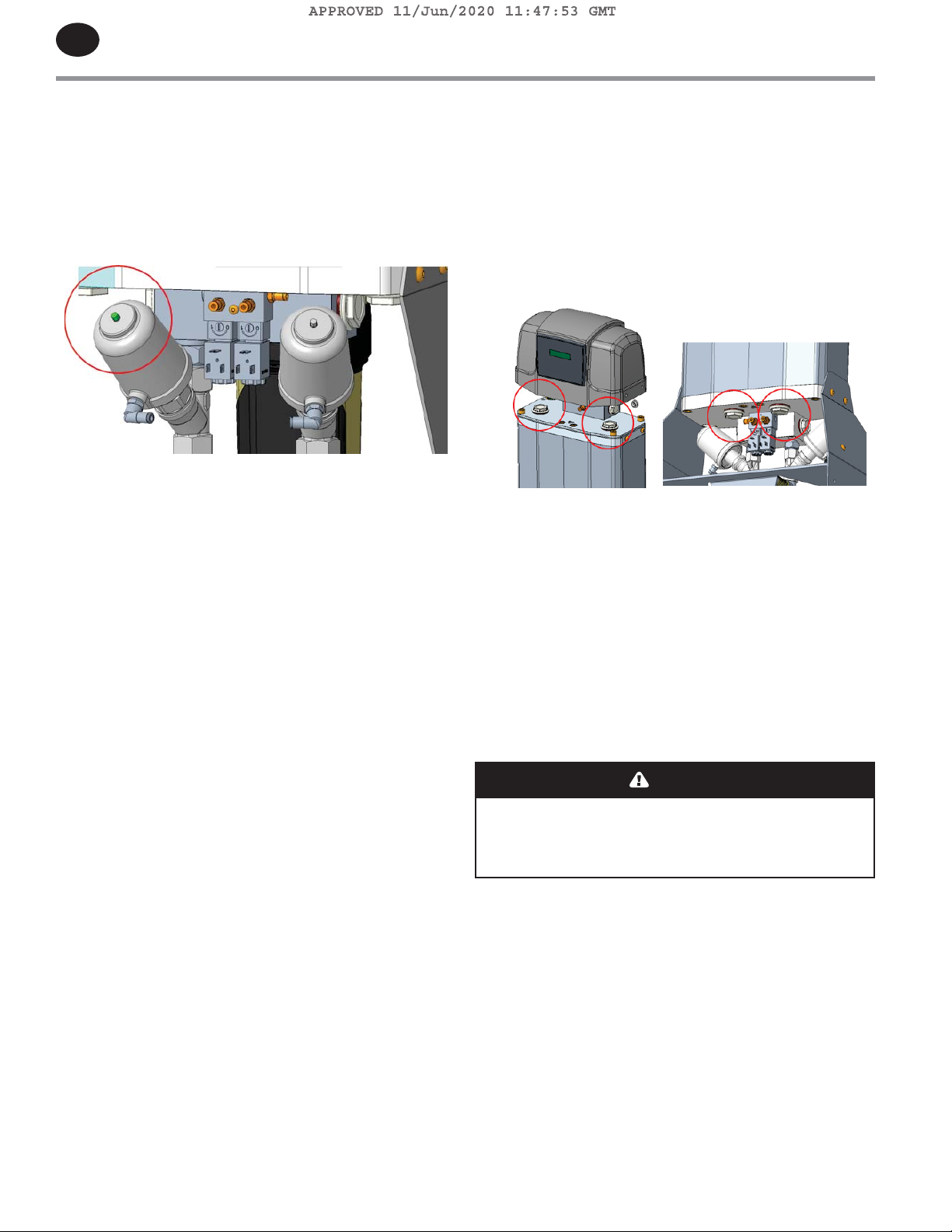
• Purge Valves – Normally-Closed (N.C.) for purge air ow.
Control air is supplied through tubing that is connected to
the side port. When control air is supplied to the valve, a
position indicator will extend from the top of the bonnet,
indicating that the valve is open (See Figure 11).
Figure 11
7.6 DESICCANT CHANGEOUT PROCEDURE
When it becomes necessary to replace the desiccant in the
towers, observe the following procedure:
Units (DA40IM - DA300IM) are furnished with ll and drain
ports (See Figure 12) on each extruded tower. Remove the
caps on both ports. Units (DA5IM - DA25IM) are not equipped
with drain ports, upper block cover needs to be taken o to
change desiccant media
Figure 12
• To assist in getting the desiccant to ow from the tower,
insert a small rod into the drain port as necessary. This
may be required as the desiccant is packed into the towers
which may interfere with the desiccant ow from the
towers.
• With the ll port plug removed, ll the dryer tower with the
appropriate grade and size desiccant.
• When the towers have been lled to the correct level,
replace the ll port plug on each tower.
• Any connections and joints disturbed in the desiccant
change out procedure should be leak tested prior to
re-commissioning the dryer.
CAUTION
Desiccant will produce dust during the change out
procedure. Be sure to wear respiratory protection
during the draining and lling process to minimize
inhalation of desiccant dust.
Page 19
A
PPROVED 11/Jun/2020 11:47:53 GM
T
8.0 TROUBLESHOOTING
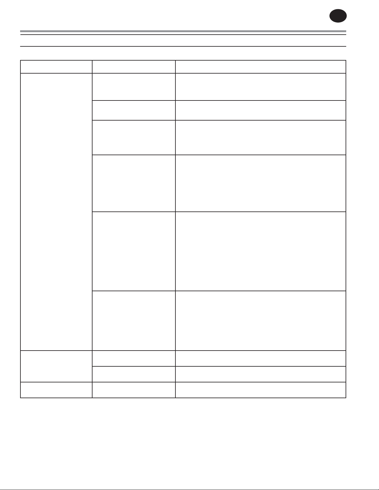
For troubleshooting procedures, refer to maintenance descriptions in SECTION 7 as required.
PROBLEM PROBABLE CAUSE CORRECTIVE ACTION
EN
Elevated Dew-point Insucient purge ow
Improper valve operation • Verify operation of main ow and purge valves.
Inlet air pressure below
design condition
Flow rate is higher than
design condition
Inlet temperature to the dryer
exceeds the rated capacity of
the dryer
Desiccant bed is ooded with
moisture. The BMI will turn
gray when this occurs
Excessive Pressure in
Purge Muer is clogged Inspect purge muers for clogging and replace as required.
Tower Designated For
Regeneration (Above
3psig (0.2 barg))
Inability to Maintain Line
Air leak across purge muer Determine if inlet valves and outlet check valves are functioning
Leaking check valve Utilize valve function to determine if inlet and outlet valves are
Pressure On Drying Tower
• Inspect purge valve & control air solenoid valves for proper
operation.
• Inspect muers for clogging.
• Inspect control air solenoid valves for proper operation.
• Check pressure source and inspect piping system for
leakages.
• Verify that the dryer was sized appropriately for the operating
conditions.
• Verify that compressor sizing is properly matched to dryer
capacity.
• For specialty systems where the outlet of the dryer is piped
to a booster compressor, verify that the ow of the booster
compressor is below the rated capacity of the dryer. Excessive
ow will uidize the desiccant bed and result in dusting and
signicantly reduce performance.
• Inspect the air compressor after-cooler and drain to ensure
proper operation. After-cooler may require cleaning in to
operate properly.
• Verify the inlet temperature does not exceed 120
o
F (50oC)
under normal operating conditions. For applications that
approach 120oF (50oC) on a continuous basis, dryer sizing
should be reviewed prior to operation of the dryer. The
standard design is rated based on an inlet condition of
o
100
F (38oC) @ 100psig (7barg) and will not deliver proper
performance if it is undersized.
• Verify that the air compressor after-cooler drain is
functioning properly.
• The desiccant will become saturated if compressed air is
permitted to ow through the dryer before it is operating.
• If this occurs, the performance of the dryer will not easily
recover and this will void the warranty on the desiccant
material.
Follow proper safety pre-cautions during this process.
properly.
functioning properly.
Page 20
A
PPROVED 11/Jun/2020 11:47:53 GM
T
EN
9.0 WIRING DIAGRAM
9.1 DA5IMDA25IM, ELECTRICAL SCHEMATIC
POWER CORD
MODEL
DA5IM 2.0
DA15I
DA25IM
LENGTH
)
(m
M
2.0
2.0
LEFT
1
3
45
67
9
10
11
POWER CORD 3 X 1.5 FLEX-JZ SEE TABLE ON
1 CONTROLLER EW 902 1
2
3 TERMINAL BLOCK, 5x2,5mm² BM 9200 1
4 FUSE HOLDER 866-3454 1
Pos. DESCRIPTION CODE QTY.
BLUE
BLACK
LPEN
1.5mm²
1.5mm²
1.5mm²
GN/YE
PE
4
PE
TOWER 1
N
N
PE
L
VALVE TOWER 1
5
1 SUPP
3 0V32 PE
2
5 SOLENOID VALVE 1
6A
POWER
230 VAC
Page 21
A
PPROVED 11/Jun/2020 11:47:53 GM
T
9.2 DA40IMDA300IM, ELECTRICAL SCHEMATIC
EN
MODEL
POWER CORD
LENGTH
(m)
DA40IM 3.5
DA55IM 3.7
DA70IM
3.8
DA100M 4.2
DA150IM 4.4
DA200IM 4.2
DA250IM 4.4
DA300IM 4.4
VALVE EMS 2 = DA200IM-DA300IM
VALVE EMS 1 = DA40IM-DA150IM
SIGNAL
EMS 2(OPTION)
EMS 1(OPTION)
PURGE VALVE 2
PURGE VALVE 1
COMPRESSOR
INTERLOCK
3 POWER
1 4..20mA
DEW POINT (OPTION)
TRANSMITTER
DEW POINT
JZ20-J-ZK2
COMR1R2R3
+V0VI1I0 AN0
2
1 SUPP
3 0V
VALVE EMS 2
1 SUPP
3 0V
VALVE EMS 1
1 SUPP
3 0V
VALVE TOWER 2
1 SUPP
3 0V
VALVE TOWER 1
6
DEW POINT
EMS
TOWER 2
TOWER 1
INTERLOCK
DEW POINT
0VDC
0VDC
24VDC
24VDC
3
0.75mm²
0.75mm²
0.75mm²
0.75mm²
0.75mm²
0.75mm²
0.75mm²
0.75mm²
L
PE
N
0.75mm²
1.5mm²
1.5mm²
BLACK
4
1.5mm²
PE
L
DARK BLUE
BLUE/WHITE
WHITE
GN/YE
24VDC
PE
0V
N
+VADJ.
54321
1 POWER SUPPLY 230VAC, 24VDC 15W RS-15-24 1
2 PLC+HMI JZ20-J-ZK2 1
3 POWER CORD 3 X 1.5 FLEX-JZ 28039 SEE TABLE ON LEFT
4 TERMINAL BLOCK, 10x2,5mm² BM 9200 1
5 FUSE HOLDER 866-3454 1
6 SOLENOID VALVE 3
Pos. DESCRIPTION CODE QTY.
7 DEW POINT EA2-TX-100-HD 1
5
1
7
230 VAC
POWER
6A
RS-15-24
Page 22
EN
A
T
10.1 DA5IM DA25IM
PPROVED 11/Jun/2020 11:47:53 GM
10.0 FLOW DIAGRAM
AIR OUTLET
LEGEND:
1) PV-1: LEFT PRESSURE VESSEL
2) PV-2: RIGHT PRESSURE VESSEL
3) DPG-1: INLET DIFFERENTIAL PRESSURE INDICATOR
4) DPG-2: OUTLET DIFFERENTIAL PRESSURE INDICATOR
5) FLT-1: HIGH EFFICIENCY INLET PREFILTER
6) FLT-2: GENERAL PURPOSE AFTERFILTER
7) EXH-1: LEFT VESSEL PURGE MUFFLER
8) EXH-2: RIGHT VESSEL PURGE MUFFLER
9) FV-3B: LEFT & RIGHT VESSEL PURGE SOLENOID CONTROL
VALVES
10
) FO-1: PURGE ORIFICE
11) CV-1 NON RETURN CHECK VALVE
: DRYING AIR FLOW
: REGENERATING AIR FLOW
: DRYER FLOW LINE
DPG
2
FO
PV
1
FLT
2
FO
1
CV
1
CV
1
1
PV
2
FV
AIR OUTLET
3B
EXH
1
DPG
1
S
EXH
2
FLT
1
Page 23
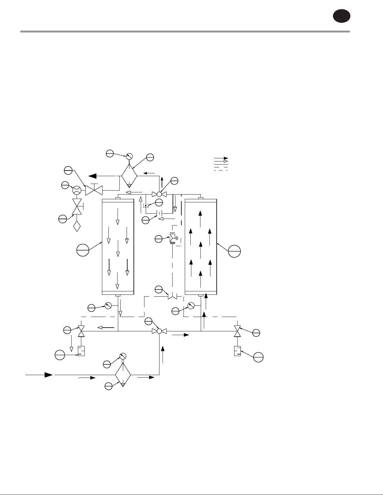
10.2 DA40IMDA150IM
A
T
HCV
.
AIR OUTLET
DPT
1
1
DPG
2
PPROVED 11/Jun/2020 11:47:53 GM
FLT
2
FV
2A
: DRYING AIR FLOW
: REGENERATING AIR FLOW
: DRYER FLOW LINE
: CONTROL FLOW / AIR LINE
: OPTIONAL LINE
EN
AIR INLET
EXH
1
HCV
2
FV
4B
.
P
PV
1
GP
1
FV
1B
DPG
1
FO
1
PR
1
PV
2
FV
3B
GP
2
FV
1A
LEGEND:
1) PV-1: LEFT PRESSURE VESSEL
2) PV-2: RIGHT PRESSURE VESSEL
3) DPG-1: INLET DIFFERENTIAL PRESSURE INDICATOR
4) DPG-2: OUTLET DIFFERENTIAL PRESSURE INDICATOR
5) FLT-1: HIGH EFFICIENCY INLET PREFILTER
6) FLT-2: GENERAL PURPOSE AFTERFILTER
7) FV-1A: LEFT / RIGHT VESSEL INLET BALL VALVE
8) FV-2A: LEFT / RIGHT VESSEL OUTLET BALL VALVE
9) FV-1B: LEFT VESSEL PURGE NC PNEUMATIC VALVE
10) FV-2B: RIGHT VESSEL PURGE NC PNEUMATIC VALVE
11) EXH-1: LEFT VESSEL PURGE MUFFLER
12) EXH-2: RIGHT VESSEL PURGE MUFFLER
13) FV-3B: LEFT & RIGHT VESSEL PURGE SOLENOID
CONTROL VALVES
14) FV-4B: EMS CONTROLING VALVE (OPTIONAL)
15) FO-1: PURGE ORIFICE
16) PR-1: PRESSURE REGULATOR
17) GP-1: LEFT VESSEL PRESSURE GAUGE
18) GP-2: RIGHT VESSEL PRESSURE GAUGE
19) HCV-1: EMS TRANSMITTER SHUT-OFF
VALVE (OPTIONAL)
20) HCV-2: EMS BLEED VALVE (OPTIONAL)
21) DPT-1: DEW POINT TRANSMITTER (OPTIONAL)
FV
2B
EXH
2
FLT
1
Page 24
EN
A
T
10.3 DA200IMDA300IM
PPROVED 11/Jun/2020 11:47:53 GM
DPG
2
FLT
2
.
.
.
PV
1
GP
1
P
AIR OUTLET
FV
2A
LEGEND:
1) PV-1: LEFT PRESSURE VESSEL
FV
4B
FO
1
PR
1
PV
2
FV
3B
GP
2
FV
1A
2) PV-2: RIGHT PRESSURE VESSEL
3) DPG-1: INLET DIFFERENTIAL PRESSURE INDICATOR
4) DPG-2: OUTLET DIFFERENTIAL PRESSURE INDICATOR
5) FLT-1: HIGH EFFICIENCY INLET PREFILTER
6) FLT-2: GENERAL PURPOSE AFTERFILTER
7) FV-1A: LEFT / RIGHT VESSEL INLET BALL VALVE
8) FV-2A: LEFT / RIGHT VESSEL OUTLET BALL VALVE
9) FV-1B: LEFT VESSEL PURGE NC PNEUMATIC VALVE
10) FV-2B: RIGHT VESSEL PURGE NC PNEUMATIC VALVE
11) EXH-1: LEFT VESSEL PURGE MUFFLER
12) EXH-2: RIGHT VESSEL PURGE MUFFLER
13) FV-3B: LEFT & RIGHT VESSEL PURGE SOLENOID
CONTROL VALVES
14) FV-4B: EMS CONTROLING VALVE (OPTIONAL)
15) FO-1: PURGE ORIFICE
16) PR-1: PRESSURE REGULATOR
17) GP-1: LEFT VESSEL PRESSURE GAUGE
18) GP-2: RIGHT VESSEL PRESSURE GAUGE
19) HCV-1: EMS TRANSMITTER SHUT-OFF
VALVE (OPTIONAL)
20) HCV-2: EMS BLEED VALVE (OPTIONAL)
21) DPT-1: DEW POINT TRANSMITTER (OPTIONAL)
: DRYING AIR FLOW
: REGENERATING AIR FLOW
: DRYER FLOW LINE
: CONTROL FLOW / AIR LINE
: OPTIONAL LINE
FV
2B
HCV
1
DPT
1
HCV
2
FV
1B
EXH
1
AIR INLET
DPG
1
FLT
1
EXH
2
Page 25
A
PPROVED 11/Jun/2020 11:47:53 GM
T
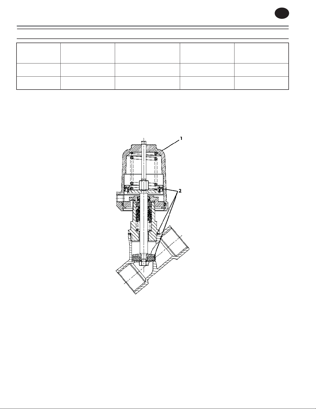
11.0 ANGLE VALVE REBUILD PARTS
EN
VALVE PART
NUMBER
17933374
47681287001
*Seal Rebuild Kit includes: Seat Seal, Head Section Seal, Exterior Lip Seal
Mounting tool is required for normally-closed valves (P.O.N.C.) only. Tool is required to decompress springs and is required for
safe dismantling of the valve.
Tool is needed to install Replacement Actuator, as well as to install Seal Rebuild kit.
Normally Closed Valve
VALVE DESCRIPTION
VALVE, ANGLE,
3/4” P.O.N.C.
VALVE, ANGLE,
1/2” P.O.N.C.
REPLACEMENT
ACTUATOR PART NUMBER
(CALLOUT 1)
17933402 17933394 17933411
47682457001 47682458001 17933411
SEAL REBUILD KIT*
PART NUMBER
(CALLOUT 2 )
MOUNTING TOOLS
Page 26
A
PPROVED 11/Jun/2020 11:47:53 GM
T
EN
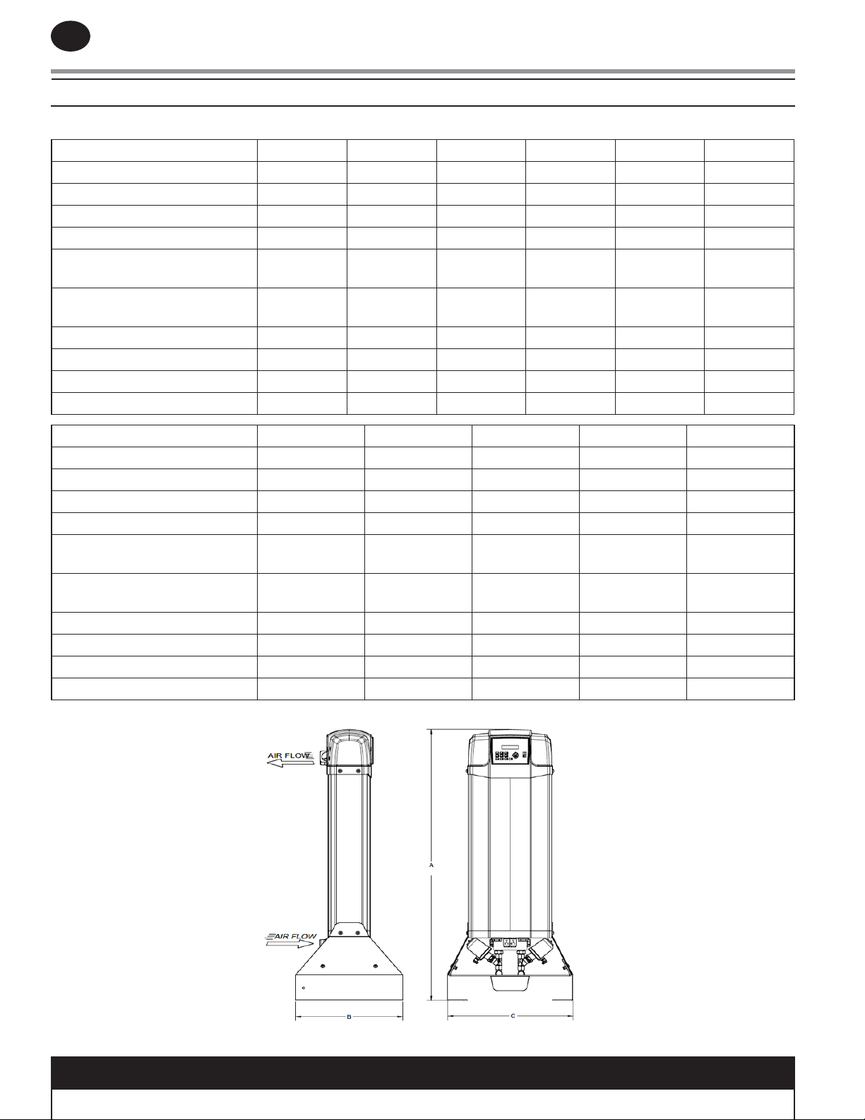
12.0 ENGINEERING SPECIFICATIONS
12.1 ENGINEERING DATA 40°C
DA5IM DA15IM DA25IM DA40IM DA55IM DA70IM
(-40°C) Inlet Capacity (m3/h) 5 1525405570
Purge (m3/h) 0,9 2,7 4,5 7,2 9,9 12,6
Desiccant per Tower (kg) 0,7 2,15 3 6,5 8,3 11
Electrical 230/1/50-60 230/1/50-60 230/1/50-60 230/1/50-60 230/1/50-60 230/1/50-60
Air In/Out Connections BSPP
(Dryer)
Air In/Out Connections BSPT
(Filter)
C -Width (mm) 238 238 238 475 475 475
B -Depth (mm) 212 212 212 365 365 365
A -Height (mm) 423 823 1073 968 1118 1318
Weight (kg) (Without Filters) 9 1621465562
3/8" 3/8" 3/8" 3/4" 3/4" 3/4"
3/8" 3/8" 3/8" 1/2" 3/4" 3/4"
DA100IM DA150IM DA200IM DA250IM DA300IM
(-40°C) Inlet Capacity (m3/h) 100 150 200 250 300
Purge (m
Desiccant per Tower (kg) 15,5 18 30,8 36 36
Electrical 230/1/50-60 230/1/50-60 230/1/50-60 230/1/50-60 230/1/50-60
Air In/Out Connections BSPP
(Dryer)
Air In/Out Connections BSPT
(Filter)
C -Width (mm) 475 475 536 536 536
B -Depth (mm) 365 365 495 495 495
A -Height (mm) 1673 1873 1705 1905 1905
Weight (kg) (Without Filters) 82 86 160 180 180
3
/h) 18 27 36 45 54
1" 1" 1.5" 1.5" 1.5"
1" 1" 1.5" 1.5" 1.5"
NOTICE
Specication information above accurate at time of publication. Refer to equipment serial label for actual
Page 27
A
PPROVED 11/Jun/2020 11:47:53 GM
T
EN
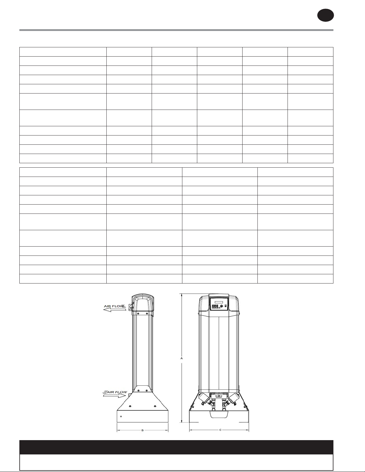
12.2 ENGINEERING DATA 70°C
DA40IM DA55IM DA70IM DA100IM DA150IM
(-70°C) Inlet Capacity (m
Purge (m
3
/h) 7,2 9,9 12,6 18 27
Desiccant per Tower (kg) 6,5 8,3 11 15,5 18
Electrical 230/1/50-60 230/1/50-60 230/1/50-60 230/1/50-60 230/1/50-60
Air In/Out Connections BSPP
(Dryer)
Air In/Out Connections BSPT
(Filter)
C -Width (mm) 475 475 475 475 475
B -Depth (mm) 365 365 365 365 365
A -Height (mm) 968 1118 1318 1673 1873
Weight (kg) (Without Filters) 46 55 62 82 86
(-70°C) Inlet Capacity (m
Purge (m3/h) 36 45 54
Desiccant per Tower (kg) 30,8 36 36
Electrical 230/1/50-60 230/1/50-60 230/1/50-60
Air In/Out Connections BSPP
(Dryer)
Air In/Out Connections BSPT
(Filter)
C -Width (mm) 536 536 536
B -Depth (mm) 495 495 495
A -Height (mm) 1705 1905 1905
Weight (kg) (Without Filters) 160 180 180
3
/h) 32 44 56 80 120
3/4" 3/4" 3/4" 1" 1"
1/2" 3/4" 3/4" 1" 1"
DA200IM DA250IM DA300IM
3
/h) 160 200 240
1.5" 1.5" 1.5"
1" 1.5" 1.5"
NOTICE
Specication information above accurate at time of publication. Refer to equipment serial label for actual
specications for units.
Page 28

A
PPROVED 11/Jun/2020 11:47:53 GM
T
ingersollrandproducts.com
© 2020 Ingersoll Rand
 Loading...